cmw500 - wireless device production test.pdf
TRANSCRIPT

8/13/2019 CMW500 - Wireless device production test.pdf
http://slidepdf.com/reader/full/cmw500-wireless-device-production-testpdf 1/34
Complimentary Reference Material
This PDF has been made available as a complimentary service for you to assist inevaluating this model for your testing requirements.
TMG offers a wide range of test equipment solutions, from renting short to longterm, buying refurbished and purchasing new. Financing options, such asFinancial Rental, and Leasing are also available on application.
TMG will assist if you are unsure whether this model will suit your requirements.
Call TMG if you need to organise repair and/or calibrate your unit.
If you click on the “Click-to-Call” logo below, you can all us for FREE!
TMG Corporate Website TMG Products Website
Disclaimer:All trademarks appearing within this PDF are trademarks of their respective owners.

8/13/2019 CMW500 - Wireless device production test.pdf
http://slidepdf.com/reader/full/cmw500-wireless-device-production-testpdf 2/34
8/13/2019 CMW500 - Wireless device production test.pdf
http://slidepdf.com/reader/full/cmw500-wireless-device-production-testpdf 3/34
T e s t & M e a s u r e m e n t
R&S®CMW500Wideband RadioCommunication Tester
Wireless deviceproduction test:breakthrough inscalability and speed

8/13/2019 CMW500 - Wireless device production test.pdf
http://slidepdf.com/reader/full/cmw500-wireless-device-production-testpdf 4/34
The new tester includes the R&S®Smart Alignment 1) high-
speed test concept plus the all-in-one architecture with
integrated vector signal generator and analyzer. These are
the prerequisites for state-of-the-art non-signaling align-
ment approaches.
The extreme scalability, test speed, and measurement
accuracy of the R&S®CMW500 translate into minimum
test costs.
Key facts
Base model: general-purpose RF power meter and CWJ
generator with List modes for fast calibration 1) of wire-
less devices
Vector signal analyzer (VSA) for transmitter vericationJ1)
Vector signal generator (VSG) for expanded receiver test-J
ing: ARB mode 1) for short setup times or online mode 1)
for complex signals with high data volume
Reference RF power measurement enabled by directJ
connection of R&S®NRP-Zxx power sensors
Easy connection to wireless devices with complex RFJ
architecture by using the integrated RF interface
State-of-the-art graphical user interface (GUI)J
SCPI remote control via LAN/GPIB interfaceJ
Ready for LXI Class CJ
Process controller with Windows® XP operating systemJ
for test routines and remote control via Windows®
Remote Desktop
The R&S®CMW500 marks the entry of a new
generation of test equipment from Rohde & Schwarz.
It allows fast and precise production testing of cur-
rent and future wireless devices from a basic mobile
phone to the most sophisticated PDA.
R&S®CMW500Wideband RadioCommunication
TesterAt a glance
2
8/13/2019 CMW500 - Wireless device production test.pdf
http://slidepdf.com/reader/full/cmw500-wireless-device-production-testpdf 5/34
R&S®CMW500Wideband RadioCommunication
TesterBenefits and keyfeatures
Multitechnology solution
Technologies: GSM/GPRS/EDGE/WCDMA /HSPA/Mobile
WiMAX™2) /CDMA2000® 3) /1xEV-DO/TD-SCDMA/GPS/
DVB-T
page 4▷
Future-ready RF parameters
3.3/6 GHz frequency range and 40/70 MHz analyzer/
generator IF bandwidth
page 5▷
Drastically reduced test costs; alignment up to ten
times faster
Innovative Rohde & Schwarz test concepts:
R&S®Smart Alignment 1) and R&S®Multi-Evaluation List
mode 1)
page 6▷
Designed for high first pass yield
High absolute accuracy plus repeatability and linearity
page 7▷
Optimized handling for production test systems
All-in-one architecture 1) with fully automatic RF path
correction 1) and Press & Go 1) applications
page 8▷
Minimum floor space
Dual-tester configuration enables simultaneous testing of
two identical wireless devices
page 10▷
Reduced operating costs due to 24-month calibrationinterval
Optimized solution for every application: selectable
calibration interval of 12 or 24 months for high absolute
accuracy or reduced costs
page 12▷
From pre-sale to service. At your doorstep.
Worldwide network of local Rohde & Schwarz experts in
over 70 countries
page 13▷
1) For explanations see glossary at end of brochure.2) “WiMAX Forum“ is a registered trademark of the WiMAX Forum. “WiMAX,“
the WiMAX Forum logo, “WiMAX Forum Certified,“ and the WiMAX Forum
Certified logo are trademarks of the WiMAX Forum.3) CDMA2000® is a registered trademark of the Telecommunications Industry
Association (TIA -USA).
Rohde & Schwarz R&S®CMW500 Wideband Radio Communication Tester 3
8/13/2019 CMW500 - Wireless device production test.pdf
http://slidepdf.com/reader/full/cmw500-wireless-device-production-testpdf 6/34
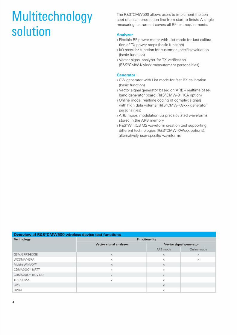
The R&S®CMW500 allows users to implement the con-
cept of a lean production line from start to finish: A single
measuring instrument covers all RF test requirements.
Analyzer
Flexible RF power meter with List mode for fast calibra-J
tion of TX power steps (basic function)
I/Q recorder function for customer-specic evaluationJ
(basic function)
Vector signal analyzer for TX vericationJ
(R&S®CMW-KMxxx measurement personalities)
Generator
CW generator with List mode for fast RX calibrationJ
(basic function)
Vector signal generator based on ARB + realtime base-J
band generator board (R&S®CMW-B110A option)
Online mode: realtime coding of complex signalsJ
with high data volume (R&S®CMW-KGxxx generator
personalities)
ARB mode: modulation via precalculated waveformsJ
stored in the ARB memory
R&S®WinIQSIM2 waveform creation tool supportingJ
different technologies (R&S®CMW-KWxxx options),
alternatively user-specic waveforms
Multitechnologysolution
Overview of R&S®CMW500 wireless device test functionsTechnology Functionality
Vector signal analyzer Vector signal generator
ARB mode Online mode
GSM/GPRS/EDGE × × ×
WCDMA/HSPA × × ×
Mobile WiMAXTM × ×
CDMA2000® 1xRTT × ×
CDMA2000® 1xEV-DO × ×
TD-SCDMA × ×
GPS ×
DVB-T ×
4
8/13/2019 CMW500 - Wireless device production test.pdf
http://slidepdf.com/reader/full/cmw500-wireless-device-production-testpdf 7/34
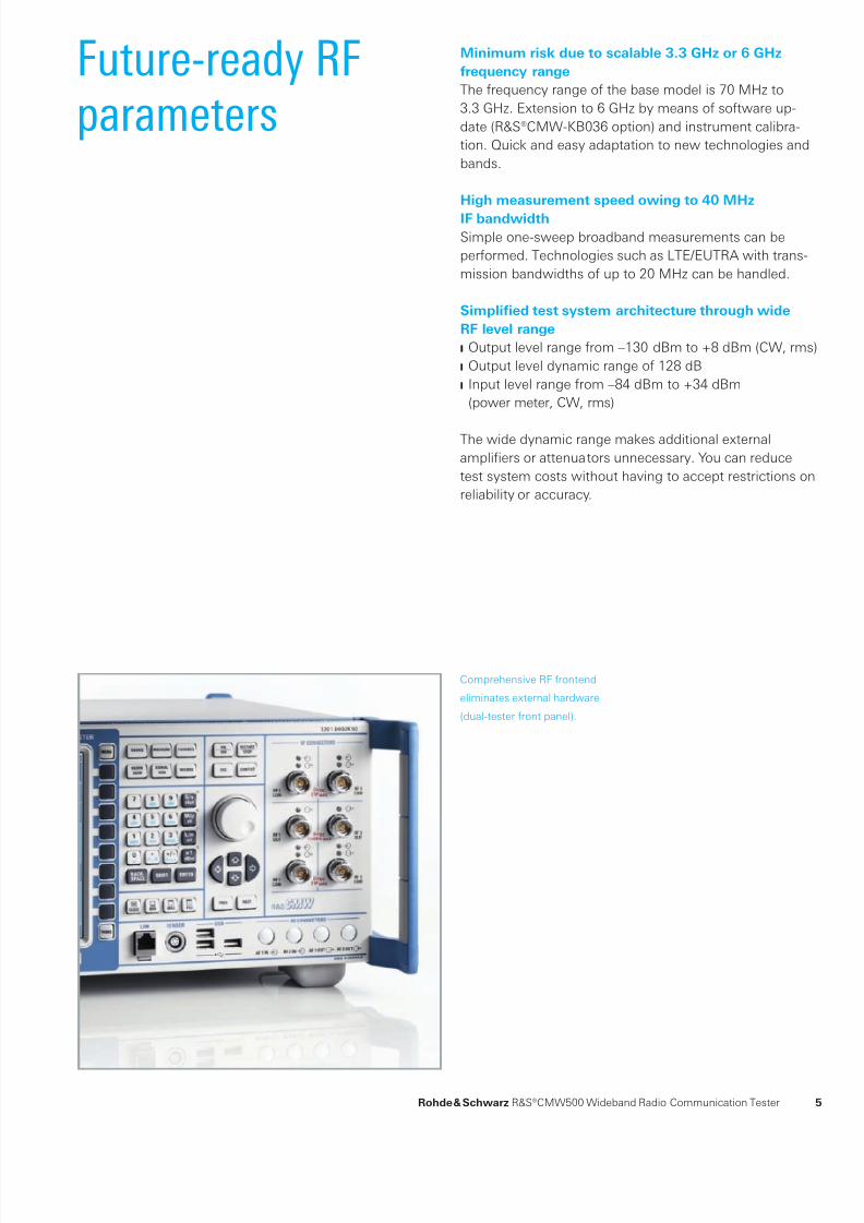
Comprehensive RF frontend
eliminates external hardware
(dual-tester front panel).
Future-ready RFparameters
Minimum risk due to scalable 3.3 GHz or 6 GHz
frequency range
The frequency range of the base model is 70 MHz to
3.3 GHz. Extension to 6 GHz by means of software up-
date (R&S®CMW-KB036 option) and instrument calibra-
tion. Quick and easy adaptation to new technologies and
bands.
High measurement speed owing to 40 MHz
IF bandwidth
Simple one-sweep broadband measurements can be
performed. Technologies such as LTE/EUTRA with trans-
mission bandwidths of up to 20 MHz can be handled.
Simplified test system architecture through wide
RF level range
Output level range from –130 dBm to +8 dBm (CW, rms)J
Output level dynamic range of 128 dBJ
Input level range from –84 dBm to +34 dBmJ
(power meter, CW, rms)
The wide dynamic range makes additional external
amplifiers or attenuators unnecessary. You can reduce
test system costs without having to accept restrictions on
reliability or accuracy.
Rohde & Schwarz R&S®CMW500 Wideband Radio Communication Tester 5
8/13/2019 CMW500 - Wireless device production test.pdf
http://slidepdf.com/reader/full/cmw500-wireless-device-production-testpdf 8/34
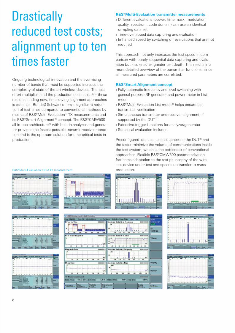
R&S®Multi-Evaluation: GSM TX measurement.
Drasticallyreduced test costs;alignment up to ten
times faster
R&S®Multi-Evaluation transmitter measurements
Different evaluations (power, time mask, modulationJ
quality, spectrum, code domain) can use an identical
sampling data set
Time-overlapped data capturing and evaluationJ
Enhanced speed by switching off evaluations that are notJ
required
This approach not only increases the test speed in com-
parison with purely sequential data capturing and evalu-ation but also ensures greater test depth. This results in a
more detailed overview of the transmitter functions, since
all measured parameters are correlated.
R&S®Smart Alignment concept
Fully automatic frequency and level switching withJ
general-purpose RF generator and power meter in List
mode
R&S®Multi-Evaluation List modeJ1) helps ensure fast
transmitter verication
Simultaneous transmitter and receiver alignment, ifJ
supported by the DUT 1)
Extensive trigger functions for analyzer/generatorJ
Statistical evaluation includedJ
Preconfigured identical test sequences in the DUT 1) and
the tester minimize the volume of communications inside
the test system, which is the bottleneck of conventional
approaches. Flexible R&S®CMW500 parameterization
facilitates adaptation to the test philosophy of the wire-
less device under test and speeds up transfer to mass
production.
Ongoing technological innovation and the ever-rising
number of bands that must be supported increase the
complexity of state-of-the-art wireless devices. The test
effort multiplies, and the production costs rise. For these
reasons, finding new, time-saving alignment approaches
is essential. Rohde & Schwarz offers a significant reduc-
tion of test times compared to conventional methods by
means of R&S®Multi-Evaluation 1) TX measurements and
its R&S®Smart Alignment 1) concept. The R&S®CMW500
all-in-one architecture 1) with built-in analyzer and genera-
tor provides the fastest possible transmit-receive interac-
tion and is the optimum solution for time-critical tests in
production.
6
8/13/2019 CMW500 - Wireless device production test.pdf
http://slidepdf.com/reader/full/cmw500-wireless-device-production-testpdf 9/34
Designed for highfirst pass yield
The R&S®CMW500 has been specially designed for
production applications: Top priority was placed on
accuracy, repeatability, and linearity. These parameter have
a direct influence on the production yield. The higher the
accuracy of these parameters, the lower the number of
DUTs that are classified as faulty although they comply
with specifications. Internal temperature sensors auto-
matically adapt the measurement accuracy to the ambi-
ent conditions. It is not necessary to perform a calibra-
tion when temperatures vary or when the instrument isswitched on.
Its high absolute accuracy plus repeatability and linearity
enable the R&S®CMW500 to be used flexibly no matter
which RF path correction concept is applied to the
individual production test station.
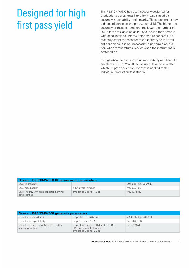
Relevant R&S®CMW500 RF power meter parametersLevel uncertainty <0.50 dB, typ. <0.30 dB
Level repeatability input level ≥–40 dBm typ. <0.01 dBLevel linearity with fixed expected nominalpower setting
level range 0 dB to –40 dB typ. <0.15 dB
Relevant R&S®CMW500 generator parameters
Output level uncertainty output level >–120 dBm <0.60 dB, typ. <0.36 dB
Output level repeatability output level <–80 dBm typ. <0.05 dB
Output level linearity with fixed RF outputattenuator setting
output level range –130 dBm to –5 dBm,GPRF generator List mode,level range 0 dB to –30 dB
typ. <0.15 dB
Rohde & Schwarz R&S®CMW500 Wideband Radio Communication Tester 7
8/13/2019 CMW500 - Wireless device production test.pdf
http://slidepdf.com/reader/full/cmw500-wireless-device-production-testpdf 10/34
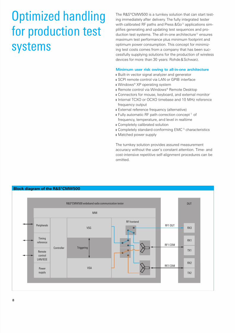
Block diagram of the R&S®CMW500
R&S®CMW500 wideband radio communication tester
RF frontend
DUT
MMI
TriggeringRF1 COM
RF2 COM
RF1 OUTVSG
VSA
Peripherals
Controller
Timing
reference
Remote
control
LAN/IEEE
Power
supply
RX3
RX1
TX1
RX2
TX2
Optimized handlingfor production testsystems
The R&S®CMW500 is a turnkey solution that can start test-
ing immediately after delivery. The fully integrated tester
with calibrated RF paths and Press & Go 1) applications sim-
plifies generating and updating test sequences and pro-
duction test systems. The all-in-one architecture 1) ensures
maximum test performance plus minimum footprint and
optimum power consumption. This concept for minimiz-
ing test costs comes from a company that has been suc-
cessfully supplying solutions for the production of wireless
devices for more than 30 years: Rohde & Schwarz.
Minimum user risk owing to all-in-one architecture
Built-in vector signal analyzer and generatorJ
SCPI remote control via LAN or GPIB interfaceJ
Windows® XP operating systemJ
Remote control via Windows® Remote DesktopJ
Connectors for mouse, keyboard, and external monitorJ
Internal TCXO or OCXO timebase and 10 MHz referenceJ
frequency output
External reference frequency (alternative)J
Fully automatic RF path correction conceptJ1) of
frequency, temperature, and level in realtime
Completely calibrated solutionJ
Completely standard-conforming EMCJ1) characteristics
Matched power supplyJ
The turnkey solution provides assured measurement
accuracy without the user’s constant attention. Time- and
cost-intensive repetitive self-alignment procedures can be
omitted.
8
8/13/2019 CMW500 - Wireless device production test.pdf
http://slidepdf.com/reader/full/cmw500-wireless-device-production-testpdf 11/34
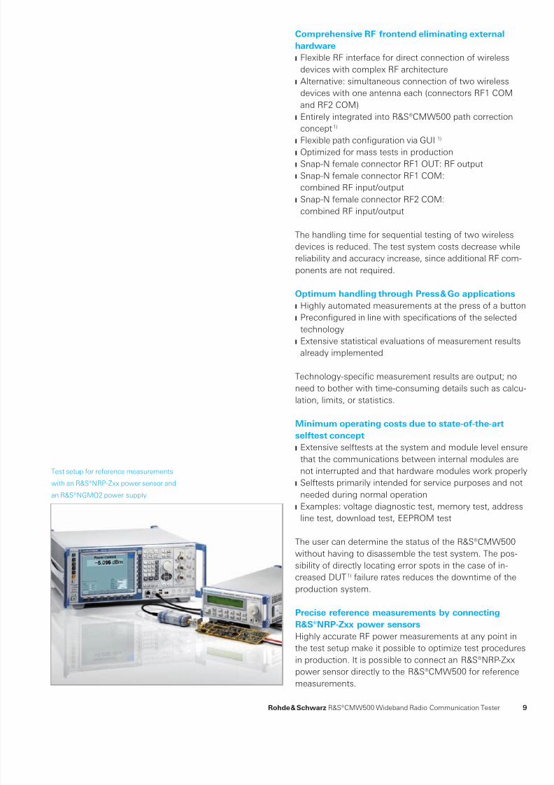
Test setup for reference measurements
with an R&S®NRP-Zxx power sensor and
an R&S®NGMO2 power supply.
Comprehensive RF frontend eliminating external
hardware
Flexible RF interface for direct connection of wirelessJ
devices with complex RF architecture
Alternative: simultaneous connection of two wirelessJ
devices with one antenna each (connectors RF1 COM
and RF2 COM)
Entirely integrated into R&S®CMW500 path correctionJ
concept 1)
Flexible path conguration via GUIJ 1)
Optimized for mass tests in productionJ
Snap-N female connector RF1 OUT: RF outputJ
Snap-N female connector RF1 COM:J
combined RF input/output
Snap-N female connector RF2 COM:J
combined RF input/output
The handling time for sequential testing of two wireless
devices is reduced. The test system costs decrease while
reliability and accuracy increase, since additional RF com-
ponents are not required.
Optimum handling through Press & Go applications
Highly automated measurements at the press of a buttonJ
Precongured in line with specications of the selectedJ
technology
Extensive statistical evaluations of measurement resultsJ
already implemented
Technology-specific measurement results are output; no
need to bother with time-consuming details such as calcu-
lation, limits, or statistics.
Minimum operating costs due to state-of-the-art
selftest concept
Extensive selftests at the system and module level ensureJ
that the communications between internal modules are
not interrupted and that hardware modules work properly
Selftests primarily intended for service purposes and notJ
needed during normal operation
Examples: voltage diagnostic test, memory test, addressJ
line test, download test, EEPROM test
The user can determine the status of the R&S®CMW500
without having to disassemble the test system. The pos-
sibility of directly locating error spots in the case of in-
creased DUT 1) failure rates reduces the downtime of the
production system.
Precise reference measurements by connecting
R&S®NRP-Zxx power sensors
Highly accurate RF power measurements at any point in
the test setup make it possible to optimize test procedures
in production. It is possible to connect an R&S®NRP-Zxx
power sensor directly to the R&S®CMW500 for reference
measurements.
Rohde & Schwarz R&S®CMW500 Wideband Radio Communication Tester 9

8/13/2019 CMW500 - Wireless device production test.pdf
http://slidepdf.com/reader/full/cmw500-wireless-device-production-testpdf 12/34
Example of dual test setup
¸CMW500 (dual)
GSM
WCDMA
Mobile phone 1
Analyzer 1
Generator 1
Analyzer 2
Generator 2
BT
DVB
GSM
WCDMA
Mobile phone 2
DVB
BT
The R&S®CMW500 can optionally be configured as a dual
tester. This configuration includes dual test resources
so that two identical wireless devices can be tested
simultaneously. This approach saves valuable floor space
in the production hall.
Minimum floorspace
10
8/13/2019 CMW500 - Wireless device production test.pdf
http://slidepdf.com/reader/full/cmw500-wireless-device-production-testpdf 13/34
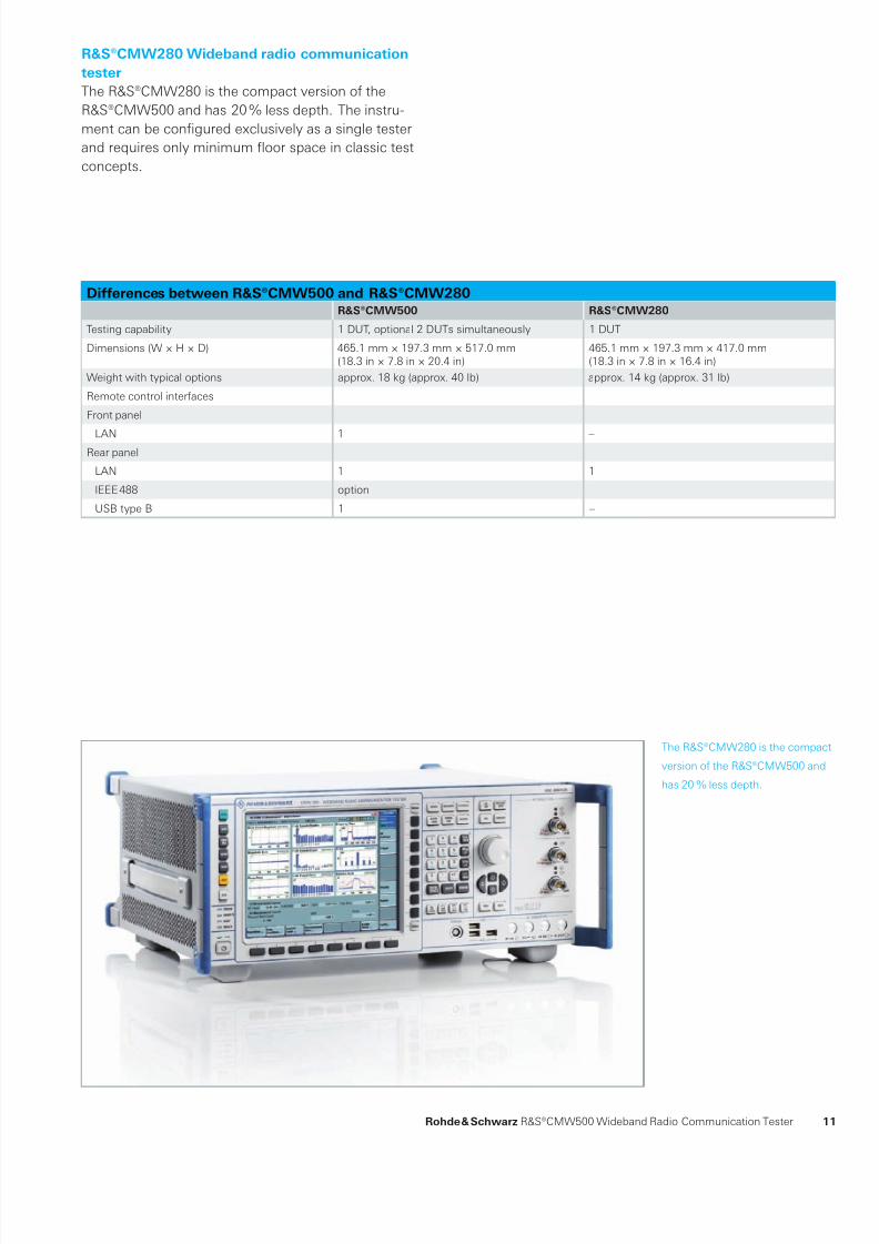
The R&S®CMW280 is the compact
version of the R&S®CMW500 and
has 20 % less depth.
R&S®CMW280 Wideband radio communication
tester
The R&S®CMW280 is the compact version of the
R&S®CMW500 and has 20 % less depth. The instru-
ment can be configured exclusively as a single tester
and requires only minimum floor space in classic test
concepts.
Differences between R&S®CMW500 and R&S®CMW280
R&S®CMW500 R&S®CMW280
Testing capability 1 DUT, optional 2 DUTs simultaneously 1 DUT
Dimensions (W × H × D) 465.1 mm × 197.3 mm × 517.0 mm(18.3 in × 7.8 in × 20.4 in)
465.1 mm × 197.3 mm × 417.0 mm(18.3 in × 7.8 in × 16.4 in)
Weight with typical options approx. 18 kg (approx. 40 lb) approx. 14 kg (approx. 31 lb)
Remote control interfaces
Front panel
LAN 1 –Rear panel
LAN 1 1
IEEE 488 option –
USB type B 1 –
Rohde & Schwarz R&S®CMW500 Wideband Radio Communication Tester 11

8/13/2019 CMW500 - Wireless device production test.pdf
http://slidepdf.com/reader/full/cmw500-wireless-device-production-testpdf 14/34
R&S®UCS calibration system.
Reducedoperating costsdue to 24-month
calibration interval
Selectable calibration interval of either 12 or 24 months.
Users can optimize costs to achieve high absolute accu-
racy or minimum test and measurement operating costs.
Relevant R&S®CMW500 RF level uncertainty
12-month calibration interval:
Analyzer <0.50 dBJ
Generator <0.60 dBJ
24-month calibration interval:
Analyzer <0.70 dBJ
Generator <0.80 dBJ
12

8/13/2019 CMW500 - Wireless device production test.pdf
http://slidepdf.com/reader/full/cmw500-wireless-device-production-testpdf 15/34
Irvine, CATijuana
Guadalajara Monterrey
Mexico Ci ty
Beaverton, OR
USA
Irving, TX
Columbia, MD
Ottawa
Mexico
Brasili a
Rio de Jane iro
Chile
ArgentinaUruguay
Sao Paul o
South Africa
Tanzania
Kenya
Sudan
Egypt
TunisiaMalta
Cyprus LebanonSyria
Jordan
Nigeria
Algeria
Ghana
Kuwait
Oman
Azerbaijan
Kazakhstan
Pakistan
SaudiArabia UnitedArab.Emirates
Delhi
Hyderabad
Mumbai
Abu Dhabi, Dubai
Bangalore
Nepal
Bangladesh
Sri Lanka
China
Chengdu
Xi´an
Beijing
OsakaTokyo
Seoul
Taipei Kaohsiung
Kanagawa
Shanghai
Hong Kong
Makati Ci ty Bangkok
Kuala Lumpur
Shenzhen
Guangzhou Hanoi
Vietnam
Taiwan
Thailand
Malaysia
Singapore
Brunei
Indonesia
Philippines
Japan
Australia
New Zealand
India
Korea
Colombia
Brazil
SlovkiaCzech R.
HungaryRomania
BulgariaMacedoniaSerbia
Netherl.
UK Denmark
NorwaySweden
FinlandRussianFederation
Belgium
Spain
Portugal
FranceSwitzerland Austria
Greece TurkeyItaly
Slovenia
Poland
Ukraine
Munich,Germany
Headquarte rs
Canada
Manaos
Paraguay
Asuncion
EstoniaLatviaLithuaniaIreland
Morocco
Botswana
Libya
MadagascarZambia Malawi
Mozambique
Uganda
Namibia
Mongolia
Islamabad
Karachi
Chennai Ho Chi Mi nh City
Gumi
Saitama
Perth
Melbourne
Canberra Sydney
Schaumburg,IL
From pre-sale toservice. At yourdoorstep.
The Rohde & Schwarz network in over 70 countries ensures
optimum on-site support by highly qualified experts. The
user risks are reduced to a minimum at all stages of the
project:
Solution nding/purchaseJ
Technical start-up/application development/integrationJ
TrainingJ
Operation/calibration/repairJ
Rohde & Schwarz R&S®CMW500 Wideband Radio Communication Tester 13

8/13/2019 CMW500 - Wireless device production test.pdf
http://slidepdf.com/reader/full/cmw500-wireless-device-production-testpdf 16/34
General-purpose RF generator
configuration menu.
ApplicationProduction teston wireless
devices with theR&S®CMW500
Economically produced RF chips exhibit variations in fre-
quency and level characteristics. The following test proce-
dure must be applied:
Step1: Calibration. Deviations from the ideal values for
transmitter and receiver must be measured, interpolated,
and stored in correction tables.
Step 2: Verification of the most important transmit and
receive parameters.
This is the only way to ensure that the specifications of
the relevant technology standard will be complied with
later during operation in the network and that the wireless
device will operate reliably.
Transmit power step alignment
The R&S®CMW500 GPRF 1) power measurement evaluates
a list of power steps at different levels and frequencies and
performs statistical evaluation. A wide range of IF filters is
available:
Gaussian lters, selectable bandwidths betweenJ
1 kHz and 10 MHz
Bandpass root raised-cosine (RRC) lters, selectableJ
bandwidths between 1 kHz and 40 MHz, roll-off 0.1
WCDMA RRC lter (3GPP TS 34.121 specication),J
3.84 MHz bandwidth, roll-off = 0.22
CDMA lter (TIA/EIA/IS-2000.2-A specication),J
1.4 MHz bandwidth
Chipset requirements R&S®CMW500 solutionNarrowband RF signal (CW),variable level and frequency
Basic functionality,GPRF1) generator
Broadband RF signal, variable leveland frequency
GPRF1)
generator combined withARB + realtime 1) baseband gen-erator module (R&S®CMW-B110Aoption) in ARB mode 1); broadbandmodulated waveforms
Complex modulated RF signalwith technology-specific channels,variable level and frequency
GPRF 1) generator combinedwith ARB + realtime 1) base-band generator module(R&S®CMW-B110A option) inARB mode 1); technology-specificwaveforms precalculated bymeans of R&S®WinIQSIM2™(R&S®CMW-KWxxx option)
14

8/13/2019 CMW500 - Wireless device production test.pdf
http://slidepdf.com/reader/full/cmw500-wireless-device-production-testpdf 17/34
General-purpose RF power
measurement menu.
Calibration of receiver signal strength
indication (RSSI) 1)
The R&S®CMW500 enables the following calibration
scenarios to be implemented as a function of the specific
chipset requirements.
The GPRF 1) generator in List mode can be operated with
preconfigured levels and frequencies. The precalculated
baseband signal, which is stored in the ARB 1) memory,
can be provided with markers that stepwise switch the list
of the GPRF 1) generator.Multisegment waveforms and marker-triggered GPRF1)
generator lists are prerequisites for minimum ARB 1) setup
times and fast RSSI 1) calibration scenarios.
Transmitter verification
The R&S®CMW500 makes it possible to perform tech-
nology-specific R&S®Multi-Evaluation measurements
(R&S®CMW-KMxxx options). The R&S®Multi-Evaluation
List mode (R&S®CMW-KM012 option) is a consistent im-
plementation of the R&S®Smart Alignment concept (pre-
defined test sequences) for transmitter verification.
Receiver verification
The receiver is checked for technology-specific absolute
sensitivity and maximum input level.
This verification is based on a BER test 1) with the
R&S®CMW500 being used as the signal source.
The ARB + realtime 1) baseband generator module
(R&S®CMW-B110A option) provides technology-specific
signals with pilot and data channels. Depending on the
applicable test requirements, the following solutions are
offered:
ARB modeJ1) based on precalculated R&S®WinIQSIM2™
waveforms (R&S®CMW-KWxxx options) or customer-
specic waveforms
Online modeJ1) for pilot channels and PRBS user data
channels with high data volume (R&S®CMW-KGxxx
options)
In single-ended BER testing 1), the bit error ratio is
evaluated in the DUT or the DUT controller.
In loop BER testing 1), the data stream to be tested is
routed back to the tester via the uplink. The R&S®CMW500
operates in non-signaling mode (no base station
emulation) and evaluates the bit error ratio of the following
channels via postprocessing:
GSM Loop CJ
WCDMA RMC 12.2 kbpsJ
TD-SCDMA RMC 12.2 kbpsJ
Rohde & Schwarz R&S®CMW500 Wideband Radio Communication Tester 15
8/13/2019 CMW500 - Wireless device production test.pdf
http://slidepdf.com/reader/full/cmw500-wireless-device-production-testpdf 18/34
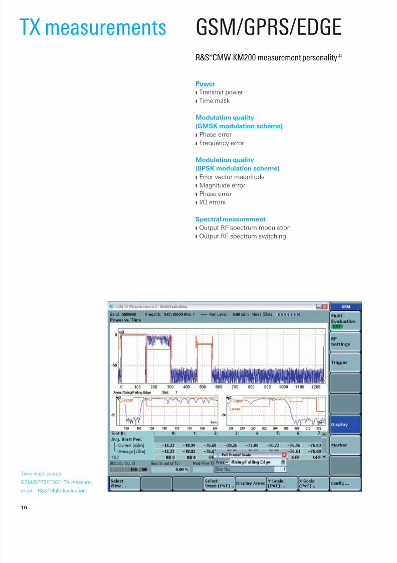
Time mask screen:
GSM/GPRS/EDGE TX measure-
ment – R&S®Multi-Evaluation.
R&S®CMW-KM200 measurement personality 4)
Power
Transmit powerJ
Time maskJ
Modulation quality
(GMSK modulation scheme)
Phase errorJ
Frequency errorJ
Modulation quality
(8PSK modulation scheme)
Error vector magnitudeJ
Magnitude errorJ
Phase errorJ
I/Q errorsJ
Spectral measurement
Output RF spectrum modulationJ
Output RF spectrum switchingJ
TX measurements GSM/GPRS/EDGE
16

8/13/2019 CMW500 - Wireless device production test.pdf
http://slidepdf.com/reader/full/cmw500-wireless-device-production-testpdf 19/34
Overview screen:
WCDMA TX measurement –
R&S®Multi-Evaluation.
WCDMAR&S®CMW-KM400 measurement personality 4)
Power
OFF powerJ
Max. powerJ
Min. powerJ
UE power versus slotJ
Modulation quality
Error vector magnitude (versus slot and versus chip)J
Magnitude error (versus slot and versus chip)J
I/Q origin offset/imbalance versus slotJ
Frequency error versus slotJ
Phase discontinuityJ
Spectral measurement
Adjacent channel leakage ratioJ
Spectrum emission maskJ
Occupied bandwidthJ
Code domain
Code domain power versus slotJ
Peak code domain errorJ
Code domain error versus slotJ
Code domain power monitorJ
Code domain error monitorJ
HSPA extensionsR&S®CMW-KM401 measurement personality
Half-slot measurementsJ
Modulation analysis of HSPA channelsJ
Code domain power measurement of HSPA channelsJ
Code domain error versus slot measurement of HSPAJ
channels
HS-DPCCH power controlJ
Phase discontinuityJ
4) R&S®Multi-Evaluation List mode supported in combination with
R&S®CMW-KM012 option.
Rohde & Schwarz R&S®CMW500 Wideband Radio Communication Tester 17

8/13/2019 CMW500 - Wireless device production test.pdf
http://slidepdf.com/reader/full/cmw500-wireless-device-production-testpdf 20/34
Overview screen:
CDMA2000® 1xRTT
TX measurement –
R&S®Multi-Evaluation.
R&S®CMW-KM800 measurement personality
Power
MS powerJ
Modulation quality
(OQPSK and HPSK modulation schemes)
Error vector magnitudeJ
Magnitude errorJ
Phase errorJ
Frequency errorJ
Carrier feedthroughJ
I/Q imbalanceJ
Waveform qualityJ
Spectral measurement
Adjacent channel powerJ
Code domain
Code domain powerJ
Code domain error powerJ
CDMA2000® 1xRTT
18
8/13/2019 CMW500 - Wireless device production test.pdf
http://slidepdf.com/reader/full/cmw500-wireless-device-production-testpdf 21/34
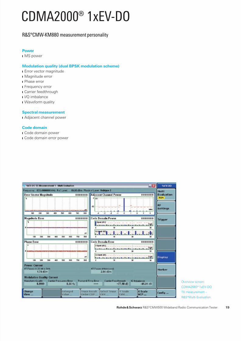
Overview screen:
CDMA2000® 1xEV-DO
TX measurement –
R&S®Multi-Evaluation.
R&S®CMW-KM880 measurement personality
Power
MS powerJ
Modulation quality (dual BPSK modulation scheme)
Error vector magnitudeJ
Magnitude errorJ
Phase errorJ
Frequency errorJ
Carrier feedthroughJ
I/Q imbalanceJ
Waveform qualityJ
Spectral measurement
Adjacent channel powerJ
Code domain
Code domain powerJ
Code domain error powerJ
CDMA2000® 1xEV-DO
Rohde & Schwarz R&S®CMW500 Wideband Radio Communication Tester 19

8/13/2019 CMW500 - Wireless device production test.pdf
http://slidepdf.com/reader/full/cmw500-wireless-device-production-testpdf 22/34
Overview screen:
Mobile WiMAX™ TX measurement
– R&S®Multi-Evaluation.
R&S®CMW-KM700 measurement personality
Power
Burst powerJ
Crest factorJ
Power versus timeJ
Modulation quality
Error vector magnitudeJ
I/Q errorsJ
Center frequency errorJ
Spectral measurement
Adjacent channel powerJ
Spectrum emission maskJ
Spectrum atnessJ
Occupied bandwidthJ
Mobile WiMAX™
20
8/13/2019 CMW500 - Wireless device production test.pdf
http://slidepdf.com/reader/full/cmw500-wireless-device-production-testpdf 23/34
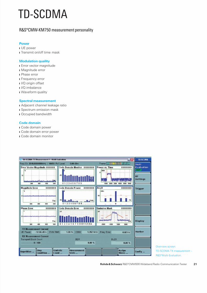
Overview screen:
TD-SCDMA TX measurement –
R&S®Multi-Evaluation.
R&S®CMW-KM750 measurement personality
Power
UE powerJ
Transmit on/off time maskJ
Modulation quality
Error vector magnitudeJ
Magnitude errorJ
Phase errorJ
Frequency errorJ
I/Q origin offsetJ
I/Q imbalanceJ
Waveform qualityJ
Spectral measurement
Adjacent channel leakage ratioJ
Spectrum emission maskJ
Occupied bandwidthJ
Code domain
Code domain powerJ
Code domain error powerJ
Code domain monitorJ
TD-SCDMA
Rohde & Schwarz R&S®CMW500 Wideband Radio Communication Tester 21
8/13/2019 CMW500 - Wireless device production test.pdf
http://slidepdf.com/reader/full/cmw500-wireless-device-production-testpdf 24/34
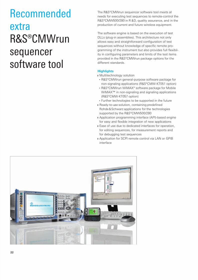
RecommendedextraR&S®CMWrun
sequencersoftware tool
The R&S®CMWrun sequencer software tool meets all
needs for executing test sequences to remote-control the
R&S®CMW500/280 in R & D, quality assurance, and in the
production of current and future wireless equipment.
The software engine is based on the execution of test
DLLs (plug-in assemblies). This architecture not only
allows easy and straightforward configuration of test
sequences without knowledge of specific remote pro-
gramming of the instrument but also provides full flexibil-ity in configuring parameters and limits of the test items
provided in the R&S®CMWrun package options for the
different standards.
Highlights
Multitechnology solutionJ
R&S®CMWrun general-purpose software package forW
non-signaling applications (R&S®CMW-KT051 option)
R&S®CMWrun WiMAX® software package for MobileW
WiMAX™ in non-signaling and signaling applications
(R&S®CMW-KT057 option)
Further technologies to be supported in the futureW
Ready-to-use solution, containing predenedJ
Rohde & Schwarz applications for the technologies
supported by the R&S®CMW500/280
Application programming interface (API)-based engineJ
for easy and exible integration of new applications
Ease of use due to dedicated interfaces for operation,J
for editing sequences, for measurement reports and
for debugging test sequences
Application for SCPI remote control via LAN or GPIBJ
interface
22
8/13/2019 CMW500 - Wireless device production test.pdf
http://slidepdf.com/reader/full/cmw500-wireless-device-production-testpdf 25/34
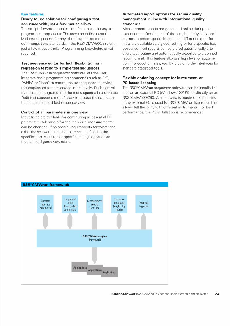
R&S®CMWrun framework
Applications
Operator
interface
(parametric)
Sequence
editor
(if.loop, while
commands)
Measurement
report
(.pdf, .xml)
Sequence
debugger
(single-step
mode)
Process
log view
ApplicationsApplications
¸CMWrun engine
(framework)
Automated report options for secure quality
management in line with international quality
standards
Measurement reports are generated online during test
execution or after the end of the test, if priority is placed
on measurement speed. In addition, different export for-
mats are available as a global setting or for a specific test
sequence. Test reports can be stored automatically after
every test routine and automatically exported to a defined
report format. This feature allows a high level of automa-tion in production lines, e.g. by providing the interfaces for
standard statistical tools.
Flexible optioning concept for instrument- or
PC-based licensing
The R&S®CMWrun sequencer software can be installed ei-
ther on an external PC (Windows® XP PC) or directly on an
R&S®CMW500/280. A smart card is required for licensing
if the external PC is used for R&S®CMWrun licensing. This
allows full flexibility with different instruments. For best
performance, the PC installation is recommended.
Key features
Ready-to-use solution for configuring a test
sequence with just a few mouse clicks
The straightforward graphical interface makes it easy to
program test sequences. The user can define custom-
ized test sequences for any of the supported mobile
communications standards in the R&S®CMW500/280 with
just a few mouse clicks. Programming knowledge is not
required.
Test sequence editor for high flexibility, from
regression testing to simple test sequences
The R&S®CMWrun sequencer software lets the user
integrate basic programming commands such as “if”,
“while” or ”loop” to control the test sequence, allowing
test sequences to be executed interactively. Such control
features are integrated into the test sequence in a separate
“edit test sequence menu” view to protect the configura-
tion in the standard test sequence view.
Control of all parameters in one view
Input fields are available for configuring all essential RF
parameters; tolerances for the individual measurements
can be changed. If no special requirements for tolerances
exist, the software uses the tolerances defined in the
specification. A customer-specific testing scenario can
thus be configured very easily.
Rohde & Schwarz R&S®CMW500 Wideband Radio Communication Tester 23

8/13/2019 CMW500 - Wireless device production test.pdf
http://slidepdf.com/reader/full/cmw500-wireless-device-production-testpdf 26/34
GlossaryTerm ExplanationACLR Adjacent channel leakage ratio
ACP Adjacent channel power
Alignment Wireless device production cycle consisting of calibration and verification
All-in-one architecture Complete, highly integrated compact solution with assured measurement accuracy and optimumhandling
ARB Generally used abbreviation for arbitrary waveform generator functionality
ARB generator mode Baseband generator mode where the modulation is implemented by means of precalculatedwaveforms stored in the ARB memory
ARB + realtime baseband generator module Generator module that supports not only the classic ARB mode but also the generation of complexmodulated signals in realtime
BB Baseband
BER Bit error ratio
Calibration Wireless device production stage during which the transmit power steps and the RSSI steps aremeasured and compared to reference values. The correction factors obtained are stored in thewireless device. Other common designations: phasing, tuning, alignment
CW Continuous wave
DSP Digital signal processor
Dual tester Device configuration including two analyzers and two generators each for simultaneous testing of
two identical wireless devicesDUT Device under test
DVI Digital video interface
EMC Electromagnetic compatibility
EVM Error vector magnitude
GPRF General-purpose radio frequency
GPRF List mode Lists containing predefined levels and frequencies for GPRF generator/power meter test sequences
GUI Graphical user interface
HW Hardware
Loop BER test in non-signaling mode Method for RX verification in production. This test is performed in non-signaling mode, i.e. withoutrealtime network emulation. The bit error ratio is evaluated through postprocessing via the uplink
ME Magnitude error
MMI Man machine interfaceOBW Occupied bandwidth
Online generator mode Baseband generator mode where complex modulated signals are generated in realtime; maximaloperation is performed via MMI
Path correction Method for increasing the measurement accuracy by taking into account the influence of frequency,temperature, and level on the RF attenuation of the measurement path
PE Phase error
PRBS Pseudo random bit sequence
Press & Go Turnkey, highly automated test functionality that is available at the press of a button
R&S®Multi-Evaluation Transmitter measurement concept where different measurement parameters use identical raw data
R&S®Smart Alignment Alignment concept where predefined identical test sequences in the DUT and in the tester reducethe data volume in the test system and significantly shorten the test time
R&S®Multi-Evaluation List mode R&S®Smart Alignment method; fast TX verification based on predefined test sequences
RF Radio frequencyRMC Reference measurement channel
RSSI Receiver signal strength indication
RX Receiver
SEM Spectrum emission mask
Single-ended BER test Modern approach to receiver verification where the stimulating signal is provided by the measuringinstrument and the BER is calculated in the DUT
Single tester Device configuration including one analyzer and one generator each
SW Software
Verification Wireless device production stage during which the most important transmit and receive parametersare checked after calibration
VSA Vector signal analyzer
VSG Vector signal generator
24

8/13/2019 CMW500 - Wireless device production test.pdf
http://slidepdf.com/reader/full/cmw500-wireless-device-production-testpdf 27/34
R&S®CMW500 specifications in briefRF generator
Frequency range base model 70 MHz to 3300 MHz
with R&S®CMW-KB036 option 70 MHz to 6000 MHz
Output level range
RF1 COM, RF2 COM 100 MHz to 3300 MHz
continuous wave (CW) –130 dBm to –5 dBmpeak envelope power (PEP) up to –5 dBm
overranging (PEP) up to 0 dBm
RF1 OUT 100 MHz to 3300 MHz
continuous wave (CW) –120 dBm to +8 dBm
peak envelope power (PEP) up to +8 dBm
overranging (PEP) up to +13 dBm
Output level uncertainty in temperature range +20 °C to +35 °C, no overranging
RF1 COM, RF2 COM output level >–120 dBm
100 MHz to 3300 MHz <0.6 dB
RF1 OUT output level >–110 dBm
100 MHz to 3300 MHz <0.8 dB
Modulation source: arbitrary waveform generator (ARB) (R&S®CMW-B110A option)
Memory size 1024 Gbyte
Word length I 16 bit
Q 16 bit
marker 4 bit to 16 bit
Sample length with 4-bit marker up to 227.55 Msample
Sample rate minimum 400 Hz
maximum 100 MHz
RF power meter
Frequency range base model 70 MHz to 3300 MHz
with R&S®CMW-KB036 option 70 MHz to 6000 MHz
Expected nominal power setting range
RF1 COM, RF2 COM 100 MHz to 3300 MHz –47 dBm to +34 dBm
Level uncertainty in temperature range +20 °C to +35 °C
RF1 COM, RF2 COM 100 MHz to 3300 MHz <0.5 dB
General dataDimensions W × H × D 465.1 mm × 197.3 mm × 517.0 mm
18.31 in × 7.77 in × 20.35 in(19” 1/1, 4 HU, 450)
Weight with typical options (single tester) approx. 18 kgapprox. 39.68 lb
Calibration interval 12 months recommended for highest accuracy,see specified RF generator and RF analyzer leveluncertainty
24 months add 0.2 dB to specified RF generator and RFanalyzer level uncertainty
Rohde & Schwarz R&S®CMW500 Wideband Radio Communication Tester 25

8/13/2019 CMW500 - Wireless device production test.pdf
http://slidepdf.com/reader/full/cmw500-wireless-device-production-testpdf 28/34
R&S®CMW500 ordering informationDesignation Type Order No.R&S®CMW500 Wideband Radio Communication Tester R&S®CMW500 1201.0002K50
Mainframe configuration, mandatory
R&S®CMW500 Wideband Radio Communication Tester, Mainframe,Frequency Range 70 MHz to 3.3 GHz
R&S®CMW-PS502 1202.5408.02
Baseband Interconnection Board (fixed link) R&S®CMW-S550A 1202.4801.02
RF Frontend Module R&S®CMW-S590A 1202.5108.02
Selection: Front Panel Without Display/Keypad (contains DVI interface) R&S®CMW-S600A 1201.0102.02
Select ion: Front Panel With Display/Keypad R&S®CMW-S600B 1201.0102.03
Mainframe configuration, optional
ARB + Realtime Baseband Generator Module R&S®CMW-B110A 1202.5508.02
IEEE Bus Interface Module (single connector) R&S®CMW-B612A 1202.5608.02
IEEE Bus Interface Module (dual connector) R&S®CMW-B612B 1202.5708.02
Digital Video Interface (DVI) Module (only required for units with display/keypad) R&S®CMW-B620A 1202.5808.02
OCXO Module R&S®CMW-B690A 1202.5908.02
OCXO Module (highly stable) R&S®CMW-B690B 1202.6004.02
Frequency Range 3.3 GHz to 6 GHz R&S®CMW-KB036 1203.0851.02
Mainframe configuration, to be ordered for dual tester, optionalBaseband Measurement Unit R&S®CMW-B100A 1202.8607.02
ARB+Realtime Baseband Generator Module R&S®CMW-B110A 1202.5508.02
RF Converter Module (TRX) R&S®CMW-B570B 1202.8659.03
RF Frontend Module R&S®CMW-B590A 1202.8707.02
Frequency Range 3.3 GHz to 6 GHz R&S®CMW-KB036 1203.0851.02
TX measurement personalities, optional
FFT Spectrum Analyzer R&S®CMW-KM010 1203.5953.02
TX Measurement, I/Q versus Slot R&S®CMW-KM011 1203.0800.02
TX Measurement, R&S®Multi-Evaluation List Mode R&S®CMW-KM012 1203.4457.02
TX Measurement, GSM/GPRS/EDGE, Uplink R&S®CMW-KM200 1203.0551.02
TX Measurement, WCDMA, Uplink R&S®CMW-KM400 1203.0700.02
TX Measurement, WCDMA HSPA Extension, Uplink R&S®CMW-KM401 1203.2954.02
TX Measurement, Mobile WiMAX™ (IEEE 802.16e) R&S®CMW-KM700 1202.6604.02
TX Measurement, TD-SCDMA, Uplink R&S®CMW-KM750 1203.2554.02
TX Measurement, CDMA2000® 1xRTT, Reverse Link R&S®CMW-KM800 1203.2602.02
TX Measurement, 1xEV-DO, Reverse Link R&S®CMW-KM880 1203.2854.02
Generator personalities, optional
Generator, GSM/GPRS/EDGE, Downlink R&S®CMW-KG200 1203.0500.02
Generator, WCDMA, Downlink R&S®CMW-KG400 1203.0651.02
Generator, WCDMA HSPA Extension, Downlink R&S®CMW-KG401 1203.2902.02
Enable R&S®WinIQSIM2™ waveforms, optional
Enable R&S®WinIQSIM2™ Waveforms, GSM/EDGE R&S®CMW-KW200 1203.0951.02
Enable R&S®WinIQSIM2™ Waveforms, WCDMA R&S®CMW-KW400 1203.1006.02
Enable R&S®WinIQSIM2™ Waveforms, WCDMA HSDPA Extension R&S®CMW-KW401 1203.1058.02
Enable R&S®WinIQSIM2™ Waveforms, WCDMA HSUPA Extension R&S®CMW-KW402 1203.1106.02
Enable R&S®WinIQSIM2™ Waveforms, GPS R&S®CMW-KW620 1203.6008.02
Enable R&S®WinIQSIM2™ Waveforms, DVB R&S®CMW-KW630 1203.6050.02
Enable R&S®WinIQSIM2™ Waveforms, WiMAX® (IEEE 802.16) R&S®CMW-KW700 1203.1358.02
Enable R&S®WinIQSIM2™ Waveforms, TD-SCDMA R&S®CMW-KW750 1203.1406.02
Enable R&S®WinIQSIM2™ Waveforms, TD-SCDMA Enhancements R&S®CMW-KW751 1203.1458.02
Enable R&S®WinIQSIM2™ Waveforms, CDMA2000® R&S®CMW-KW800 1203.1506.02
Enable R&S®WinIQSIM2™ Waveforms, 1xEV-DO R&S®CMW-KW880 1203.1558.02
26

8/13/2019 CMW500 - Wireless device production test.pdf
http://slidepdf.com/reader/full/cmw500-wireless-device-production-testpdf 29/34
R&S®CMW500 (single) configuration guide
Dual-tester configuration
The mainframe contains one RF converter module (TRX)
and one baseband measurement unit (BB Meas). One RF
frontend (R&S®CMW-S590A) is mandatory and must be
selected. In addition, an RF frontend (R&S®CMW-B590A),
an RF converter (R&S®CMW-B570B) and a measurement
unit (R&S®CMW-B100A) must be ordered.
Two each of the following products must be ordered:
Baseband generator module (R&S®CMW-B110A)J
Extended frequency range 3.3 GHz to 6 GHzJ
(R&S®CMW-KB036)
Software licenses (R&S®CMW-KMxxx TX measurementJ
personalities, R&S®CMW-KGxxx generator personalities,
R&S®CMW-KWxxx for R&S®WinIQSIM2™ enabling).
Hardware option
Software option
SelectionMMI/front panel
R&S®CMW-S600A (without display or keypad)
R&S®CMW-S600B (with display and keypad)
ARB + realtime baseband generator module
R&S®CMW-B110A
DVI interface
R&S®CMW-B620A
Generator personalities
– R&S®CMW-KG200 GSM/GPRS/EDGE
– R&S®CMW-KG400 WCDMA
– R&S®CMW-KG401 HSPA extension
Enable R&S®WinIQSIM2™ waveforms
– R&S®CMW-KW200 GSM/GPRS/EDGE
– R&S®CMW-KW400 WCDMA
– R&S®CMW-KW401 HSDPA extension
– R&S®CMW-KW402 HSUPA extension
– R&S®CMW-KW620 GPS
– R&S®CMW-KW630 DVB
– R&S®CMW-KW700 Mobile WiMAX™
– R&S®CMW-KW750 TD-SCDMA
– R&S®CMW-KW751 TD-SCDMA enhancements
– R&S®CMW-KW800 CDMA2000®
– R&S®CMW-KW880 1xEV-DO
R&S®CMW500 mainframe
R&S®CMW-PS502
Frequency range 3.3 GHz to 6 GHz
R&S®CMW-KB036
OCXO module
R&S®CMW-B690A
R&S®CMW-B690B (highly stable)
IEEE bus interface
R&S®CMW-B612A
Measurement personalities
R&S®CMW-M010 spectrum analyzer
R&S®CMW-KM011 I/Q versus slot
R&S®CMW-KM012 multi-evaluation List mode
– R&S®CMW-KM200 GSM/GPRS/EDGE – R&S®CMW-KM400 WCDMA
– R&S®CMW-KM401 HSPA extension
– R&S®CMW-KM700 Mobile WiMAX™
– R&S®CMW-KM750 TD-SCDMA
– R&S®CMW-KM800 CDMA2000®
– R&S®CMW-KM880 1xEV-DO
Mandatory
R&S®CMW-S550A fixed baseband link
R&S®CMW-S590A RF frontend module
Rohde & Schwarz R&S®CMW500 Wideband Radio Communication Tester 27
8/13/2019 CMW500 - Wireless device production test.pdf
http://slidepdf.com/reader/full/cmw500-wireless-device-production-testpdf 30/34
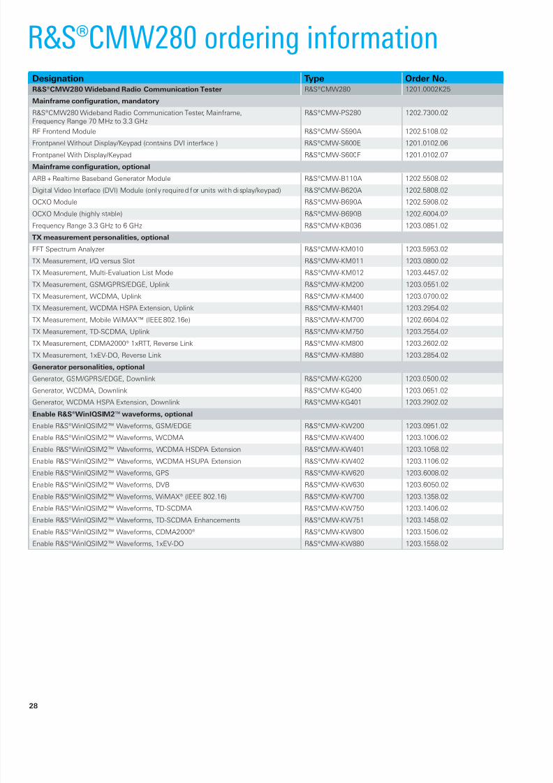
R&S®CMW280 ordering informationDesignation Type Order No.R&S®CMW280 Wideband Radio Communication Tester R&S®CMW280 1201.0002K25
Mainframe configuration, mandatory
R&S®CMW280 Wideband Radio Communication Tester, Mainframe,Frequency Range 70 MHz to 3.3 GHz
R&S®CMW-PS280 1202.7300.02
RF Frontend Module R&S®CMW-S590A 1202.5108.02
Frontpanel Without Display/Keypad (contains DVI interface ) R&S®CMW-S600E 1201.0102.06
Frontpanel With Display/Keypad R&S®CMW-S600F 1201.0102.07
Mainframe configuration, optional
ARB + Realtime Baseband Generator Module R&S®CMW-B110A 1202.5508.02
Digital Video Interface (DVI) Module (only required for units with display/keypad) R&S®CMW-B620A 1202.5808.02
OCXO Module R&S®CMW-B690A 1202.5908.02
OCXO Module (highly stable) R&S®CMW-B690B 1202.6004.02
Frequency Range 3.3 GHz to 6 GHz R&S®CMW-KB036 1203.0851.02
TX measurement personalities, optional
FFT Spectrum Analyzer R&S®CMW-KM010 1203.5953.02
TX Measurement, I/Q versus Slot R&S®CMW-KM011 1203.0800.02
TX Measurement, Multi-Evaluation List Mode R&S®CMW-KM012 1203.4457.02TX Measurement, GSM/GPRS/EDGE, Uplink R&S®CMW-KM200 1203.0551.02
TX Measurement, WCDMA, Uplink R&S®CMW-KM400 1203.0700.02
TX Measurement, WCDMA HSPA Extension, Uplink R&S®CMW-KM401 1203.2954.02
TX Measurement, Mobile WiMAX™ (IEEE 802.16e) R&S®CMW-KM700 1202.6604.02
TX Measurement, TD-SCDMA, Uplink R&S®CMW-KM750 1203.2554.02
TX Measurement, CDMA2000® 1xRTT, Reverse Link R&S®CMW-KM800 1203.2602.02
TX Measurement, 1xEV-DO, Reverse Link R&S®CMW-KM880 1203.2854.02
Generator personalities, optional
Generator, GSM/GPRS/EDGE, Downlink R&S®CMW-KG200 1203.0500.02
Generator, WCDMA, Downlink R&S®CMW-KG400 1203.0651.02
Generator, WCDMA HSPA Extension, Downlink R&S®CMW-KG401 1203.2902.02
Enable R&S®WinIQSIM2™ waveforms, optional
Enable R&S®WinIQSIM2™ Waveforms, GSM/EDGE R&S®CMW-KW200 1203.0951.02
Enable R&S®WinIQSIM2™ Waveforms, WCDMA R&S®CMW-KW400 1203.1006.02
Enable R&S®WinIQSIM2™ Waveforms, WCDMA HSDPA Extension R&S®CMW-KW401 1203.1058.02
Enable R&S®WinIQSIM2™ Waveforms, WCDMA HSUPA Extension R&S®CMW-KW402 1203.1106.02
Enable R&S®WinIQSIM2™ Waveforms, GPS R&S®CMW-KW620 1203.6008.02
Enable R&S®WinIQSIM2™ Waveforms, DVB R&S®CMW-KW630 1203.6050.02
Enable R&S®WinIQSIM2™ Waveforms, WiMAX® (IEEE 802.16) R&S®CMW-KW700 1203.1358.02
Enable R&S®WinIQSIM2™ Waveforms, TD-SCDMA R&S®CMW-KW750 1203.1406.02
Enable R&S®WinIQSIM2™ Waveforms, TD-SCDMA Enhancements R&S®CMW-KW751 1203.1458.02
Enable R&S®WinIQSIM2™ Waveforms, CDMA2000® R&S®CMW-KW800 1203.1506.02
Enable R&S®WinIQSIM2™ Waveforms, 1xEV-DO R&S®CMW-KW880 1203.1558.02
28
8/13/2019 CMW500 - Wireless device production test.pdf
http://slidepdf.com/reader/full/cmw500-wireless-device-production-testpdf 31/34
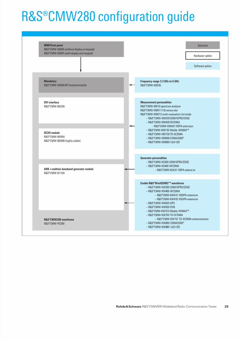
Hardware option
Software option
SelectionMMI/front panel
R&S®CMW-S600E (without display or keypad)
R&S®CMW-S600F (with display and keypad)
ARB + realtime baseband generator module
R&S®CMW-B110A
DVI interface
R&S®CMW-B620A
Generator personalities
– R&S®CMW-KG200 GSM/GPRS/EDGE
– R&S®CMW-KG400 WCDMA
– R&S®CMW-KG401 HSPA extension
Enable R&S®WinIQSIM2™ waveforms
– R&S®CMW-KW200 GSM/GPRS/EDGE
– R&S®CMW-KW400 WCDMA
– R&S®CMW-KW401 HSDPA extension
– R&S®CMW-KW402 HSUPA extension
– R&S®CMW-KW620 GPS
– R&S®CMW-KW630 DVB
– R&S®CMW-KW700 Mobile WiMAX™
– R&S®CMW-KW750 TD-SCDMA
– R&S®CMW-KW751 TD-SCDMA enhancements
– R&S®CMW-KW800 CDMA2000®
– R&S®CMW-KW880 1xEV-DO
R&S®CMW280 mainframe
R&S®CMW-PS280
Frequency range 3.3 GHz to 6 GHz
R&S®CMW-KB036
OCXO module
R&S®CMW-B690A
R&S®CMW-B690B (highly stable)
Measurement personalities
R&S®CMW-M010 spectrum analyzer
R&S®CMW-KM011 I/Q versus slot
R&S®CMW-KM012 multi-evaluation List mode
– R&S®CMW-KM200 GSM/GPRS/EDGE – R&S®CMW-KM400 WCDMA
– R&S®CMW-KM401 HSPA extension
– R&S®CMW-KM700 Mobile WiMAX™
– R&S®CMW-KM750 TD-SCDMA
– R&S®CMW-KM800 CDMA2000®
– R&S®CMW-KM880 1xEV-DO
Mandatory
R&S®CMW-S590A RF frontend module
R&S®CMW280 configuration guide
Rohde & Schwarz R&S®CMW500 Wideband Radio Communication Tester 29

8/13/2019 CMW500 - Wireless device production test.pdf
http://slidepdf.com/reader/full/cmw500-wireless-device-production-testpdf 32/34
R&S®CMW280 single tester
Designation Type Order No. QuantityR&S®CMW280 Wideband Radio Communication Tester R&S®CMW280 1201.0002K25 1
R&S®CMW280 Wideband Radio Communication Tester, Mainframe,Frequency Range 70 MHz to 3.3 GHz
R&S®CMW-PS280 1202.7300.02 1
Baseband Interconnection Board (fixed link) R&S®CMW-S550A 1202.4801.02 1
RF Frontend Module R&S®CMW-S590A 1202.5108.02 1
Selection: Front Panel Without Display/Keypad (contains DVI interface) R&S®CMW-S600A 1201.0102.02 1
ARB + Realtime Baseband Generator Module R&S®CMW-B110A 1202.5508.02 1
TX Measurement, GSM/GPRS/EDGE, Uplink R&S®CMW-KM200 1203.0551.02 1
TX Measurement, WCDMA, Uplink R&S®CMW-KM400 1203.0700.02 1
Enable R&S®WinIQSIM2™ Waveforms, GSM/EDGE R&S®CMW-KW200 1203.0951.02 1
Enable R&S®WinIQSIM2™ Waveforms, WCDMA R&S®CMW-KW400 1203.1006.02 1
R&S®CMW500 single tester
Designation Type Order No. QuantityR&S®CMW500 Wideband Radio Communication Tester R&S®CMW500 1201.0002K50 1
R&S®CMW500 Wideband Radio Communication Tester, Mainframe,Frequency Range 70 MHz to 3.3 GHz
R&S®CMW-PS502 1202.5408.02 1
Baseband Interconnection Board (fixed link) R&S®CMW-S550A 1202.4801.02 1
RF Frontend Module R&S®CMW-S590A 1202.5108.02 1
Selection: Front Panel Without Display/Keypad (contains DVI interface) R&S®CMW-S600A 1201.0102.02 1
ARB + Realtime Baseband Generator Module R&S®CMW-B110A 1202.5508.02 1
TX Measurement, GSM/GPRS/EDGE, Uplink R&S®CMW-KM200 1203.0551.02 1
TX Measurement, WCDMA, Uplink R&S®CMW-KM400 1203.0700.02 1
Enable R&S®WinIQSIM2™ Waveforms, GSM/EDGE R&S®CMW-KW200 1203.0951.02 1
Enable R&S®WinIQSIM2™ Waveforms, WCDMA R&S®CMW-KW400 1203.1006.02 1
R&S®CMW500 dual tester
Designation Type Order No. QuantityR&S®CMW500 Wideband Radio Communication Tester R&S®CMW500 1201.0002K50 1
R&S®CMW500 Wideband Radio Communication Tester, Mainframe,
Frequency Range 70 MHz to 3.3 GHz
R&S®CMW-PS502 1202.5408.02 1
Baseband Interconnection Board (fixed link) R&S®CMW-S550A 1202.4801.02 1
RF Frontend Module R&S®CMW-S590A 1202.5108.02 1
Selection: Front Panel Without Display/Keypad (contains DVI interface) R&S®CMW-S600A 1201.0102.02 1
Baseband Measurement Unit R&S®CMW-B100A 1202.8607.02 1
ARB + Realtime Baseband Generator Module R&S®CMW-B110A 1202.5508.02 2
RF Converter Module (TRX) R&S®CMW-B570B 1202.8659.03 1
RF Frontend Module R&S®CMW-B590A 1202.8707.02 1
TX Measurement, GSM/GPRS/EDGE, Uplink R&S®CMW-KM200 1203.0551.02 2
TX Measurement, WCDMA, Uplink R&S®CMW-KM400 1203.0700.02 2
Enable R&S®WinIQSIM2™ Waveforms, GSM/EDGE R&S®CMW-KW200 1203.0951.02 2
Enable R&S®WinIQSIM2™ Waveforms, WCDMA R&S®CMW-KW400 1203.1006.02 2
Typical configurationGSM/EDGE/WCDMA
30
8/13/2019 CMW500 - Wireless device production test.pdf
http://slidepdf.com/reader/full/cmw500-wireless-device-production-testpdf 33/34
Your local Rohde & Schwarz expert will help you to find the
solution that is optimally suited to your requirements and
will be glad to prepare a custom offer for you.
To find your nearest Rohde & Schwarz representative, visit:
www.sales.rohde-schwarz.com
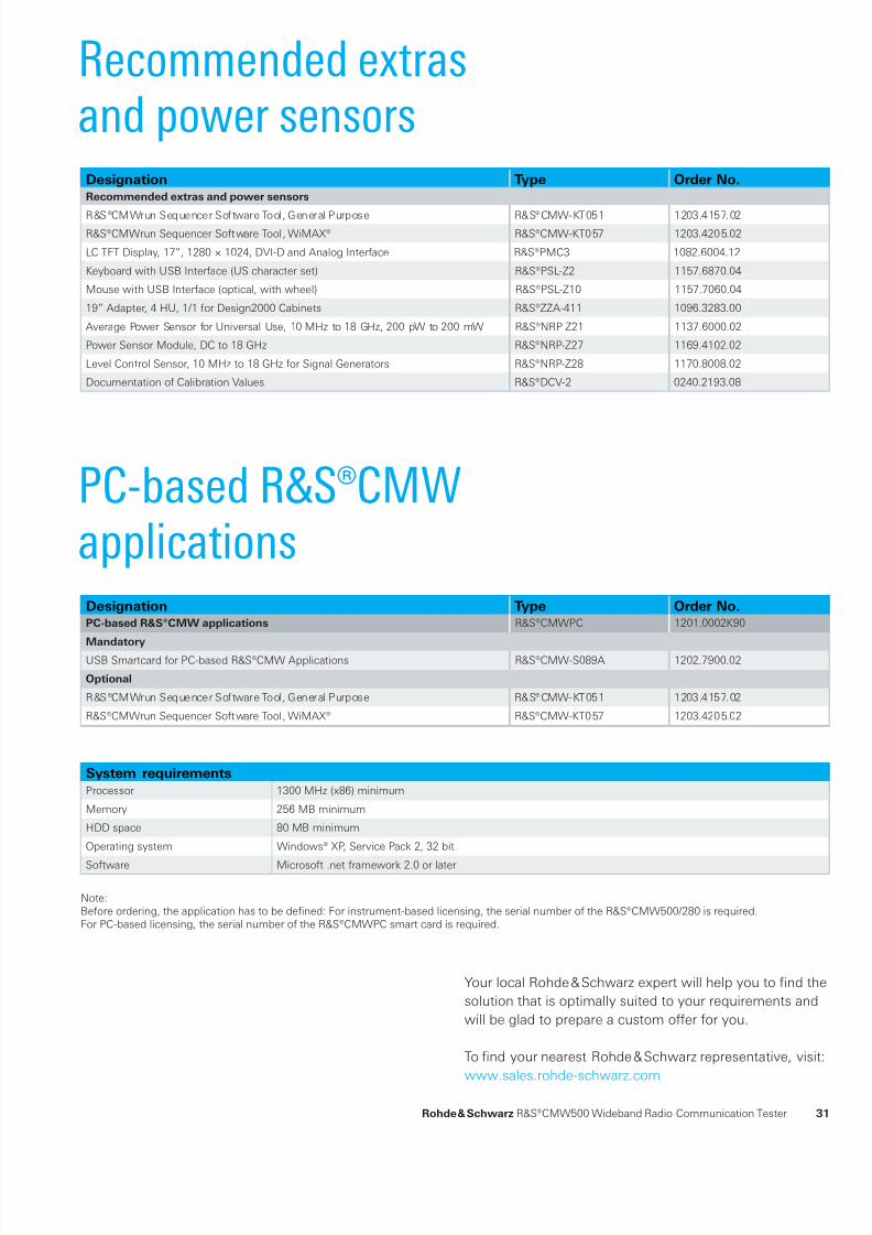
Recommended extrasand power sensors
PC-based R&S®CMWapplications
System requirements
Processor 1300 MHz (x86) minimum
Memory 256 MB minimum
HDD space 80 MB minimum
Operating system Windows® XP, Service Pack 2, 32 bit
Software Microsoft .net framework 2.0 or later
Note:Before ordering, the application has to be defined: For instrument-based licensing, the serial number of the R&S®CMW500/280 is required.For PC-based licensing, the serial number of the R&S®CMWPC smart card is required.
Designation Type Order No.Recommended extras and power sensors
R&S®CMWrun Sequencer Software Tool, General Purpose R&S®CMW-KT051 1203.4157.02R&S®CMWrun Sequencer Software Tool, WiMAX® R&S®CMW-KT057 1203.4205.02
LC TFT Display, 17”, 1280 × 1024, DVI-D and Analog Interface R&S®PMC3 1082.6004.12
Keyboard with USB Interface (US character set) R&S®PSL-Z2 1157.6870.04
Mouse with USB Interface (optical, with wheel) R&S®PSL-Z10 1157.7060.04
19” Adapter, 4 HU, 1/1 for Design2000 Cabinets R&S®ZZA-411 1096.3283.00
Average Power Sensor for Universal Use, 10 MHz to 18 GHz, 200 pW to 200 mW R&S®NRP-Z21 1137.6000.02
Power Sensor Module, DC to 18 GHz R&S®NRP-Z27 1169.4102.02
Level Control Sensor, 10 MHz to 18 GHz for Signal Generators R&S®NRP-Z28 1170.8008.02
Documentation of Calibration Values R&S®DCV-2 0240.2193.08
Designation Type Order No.PC-based R&S®CMW applications R&S®CMWPC 1201.0002K90
Mandatory
USB Smartcard for PC-based R&S®CMW Applications R&S®CMW-S089A 1202.7900.02
Optional
R&S®CMWrun Sequencer Software Tool, General Purpose R&S®CMW-KT051 1203.4157.02
R&S®CMWrun Sequencer Software Tool, WiMAX® R&S®CMW-KT057 1203.4205.02
Rohde & Schwarz R&S®CMW500 Wideband Radio Communication Tester 31

8/13/2019 CMW500 - Wireless device production test.pdf
http://slidepdf.com/reader/full/cmw500-wireless-device-production-testpdf 34/34
Certifed Environmental System
ISO 14001DQS REG. NO 1954 UM
Certifed Quality System
ISO 9001DQS REG. NO 1954 QM
Rohde & Schwarz GmbH & Co. KG
Mühldorfstraße 15 | 81671 München
Phone +49 89 41 290 | Fax +49 89 41 29 121 64
www.rohde-schwarz.com
R&S® is a registered trademark of Rohde & Schwarz GmbH & Co. KG
Trade names are trademarks of the owners | Printed in Germany (ch)
For data sheet, see
PD 5213.9211.22
and www.rohde-schwarz.com
rvice you can rely on
70 countries
rson-to-person
stomized and exible
uality with a warranty
o hidden terms
About Rohde & Schwarz
Rohde & Schwarz is an independent group of companies
specializing in electronics. It is a leading supplier of solu-
tions in the fields of test and measurement, broadcasting,
radiomonitoring and radiolocation, as well as secure com-
munications. Established 75 years ago, Rohde & Schwarz
has a global presence and a dedicated service network in
over 70 countries. Company headquarters are in Munich,
Germany.
Regional contact
Europe, Africa, Middle East
+49 1805 12 42 42* or +49 89 4129 137 74
North America
1 888 TEST RSA (1 888 837 87 72)
Latin America
+1 410 910 79 88
Asia/Pacific
+65 65 13 04 88