cnc cylindrical grinders - bulmakmetal...
TRANSCRIPT
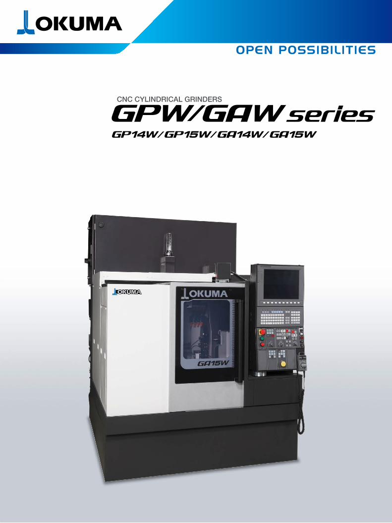
CNC CYLINDRICAL GRINDERS
CNC CYLINDRICAL GRINDERS
Photos shown in this brochure may also show optional equipment.
1 2
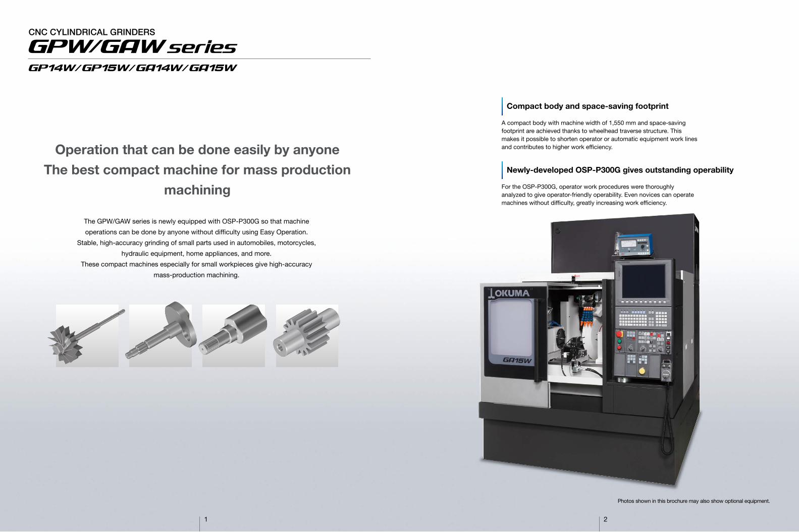
The GPW/GAW series is newly equipped with OSP-P300G so that machine
operations can be done by anyone without difficulty using Easy Operation.
Stable, high-accuracy grinding of small parts used in automobiles, motorcycles,
hydraulic equipment, home appliances, and more.
These compact machines especially for small workpieces give high-accuracy
mass-production machining.
Newly-developed OSP-P300G gives outstanding operability
For the OSP-P300G, operator work procedures were thoroughly analyzed to give operator-friendly operability. Even novices can operate machines without difficulty, greatly increasing work efficiency.
Compact body and space-saving footprint
A compact body with machine width of 1,550 mm and space-saving footprint are achieved thanks to wheelhead traverse structure. This makes it possible to shorten operator or automatic equipment work lines and contributes to higher work efficiency.Operation that can be done easily by anyone
The best compact machine for mass productionmachining

3 4
The best monozukuri practices balance
high-accuracy machining and workability
Wide
Wheelhead
Non-round plain bearing wheel spindle with a dynamic pressure structure supports the wheel spindle with wedge-shaped oil film pressure that is generated by wheel spindle rotation. Retention strength is a powerful 1 t, in addition to which wheel rotation accuracy is kept to within 0.01 µm for a good balance of high accuracy grinding even in heavy-duty cutting. Also, because the wheel spindle has no metal contact, its original performance is maintained semi-permanently.
Stress analysis with FEM analysis
Workpiece headstock Tailstock
● X-axis feedrate: ø30 m/min● Z-axis feedrate: 20 m/min
Smaller machine spaceachieved with use ofwheelhead traverse structure
A wheelhead traverse structure requires a stronger foundation than a table traverse structure. Okuma’s high-rigidity technology meets the conditions needed for a wheelhead traverse structure to achieve a compact body.
Technology on every part ofthe machine contributes tohigher machining accuracy
An oil pan structure to minimize effects on the coolant, high following characteristics carefully fitted with a V-plane slideway, and other individual technologies on each part of the machine further improve machining accuracy.
Superior user-friendlydesign supports automation
The upper portion of the front door can accommodate various loader positions. Line flexibility from the space-saving design also contributes to greater automation.
Chatter control functionsupports stable,high-accuracy machining
“Chatter control function” automatically changes wheel speed and controls regenerative chatter. Stable machining accuracies can be maintained at all times.
High machining efficiency maintainedwith wide V plane guideway
A wide V plane guideway is used that expands the V plane span of the table guideway. Higher workpiece support rigidity enables grinding with full power of 5.5 kW (optional 7.5 kW). The grinding load on the wheelhead during heavy-duty grinding is supported by wide V plane guideway for high machining efficiency.
Machining time is shortened with highspeed feed at the top level in the class
Structure with unrivaled high following characteristics gives high feed speeds of ø30 m/min on the X axis and 20 m/min on the Z axis. Shorter non-cutting times contribute to improved machining efficiency.
Reduced burden in adjusting for taperchanges with use of tailstock withmanual taper compensation function
Adjustments can be easily made for taper changes that occur with tailstock travel
Support point
Wedge-shapedoil membrane
Oil pooling
Machine width:1,550 mm (61.02)
Grindingwheel spindle
Bearing
Dynamic pressure bearing structure gives efficientmachining even in heavy-duty cutting

5 6
Automatic operations and setup work are done from the running screen. Press the “Running screen” key on the operation panel or the Auto/MDI mode key to display the running screen. You can switch to the actual position sheet, setup settings sheet, or manual grinding sheet as needed
■ Running screen indicationsOn the actual position sheet of the running screen, in addition to actual position display, workpiece selection/program selection/schedule selection are possible with use of the function keys.
■ Actual position sheet (program selection)
On the setup settings sheet on the running screen, guideways, various coordinate values, and other settings for different purposes are displayed. To minimize switching between screens, settings for running conditions selection/diagram zero point/zero point shift/workpiece locator offset can be made.
■ Setup settings sheetOn the manual grinding sheet on the running screen, setting parameters for the grinding wheel and spindle speed used, traverse running, and oscillation operation are displayed. To minimize switching between screens, operation and setting items related to manual operation are brought together on a single screen
■ Manual grinding sheet
Grinding wheel data are managed in the tool data settings. Grinding wheel data are displayed by pressing the “tool data setting” button on the operation panel.The setting screen shows a list of registered grinding wheel data and individual screens related to each grinding wheel.
■ Tool data setting
Sheet switch
Satisfaction from complete control of a machine toolAs a “machine & control” builder, Okuma makes further strides in machine tool manufacturing with this superb Control featuring “Easy Operation.” Okuma took a close look at the way machinists actually operate machine tools, to help them create smoother and more effective ways of producing parts. Novice operators as well as professional machinists get complete control—and satisfaction.Moreover, what you want to see and do conveniently come together in a “single-mode operation.”First, select one of three operation screens. Then simply touch the screen or press a function key to see and do your job.
OSP-P300GOkuma Control
■ Setup operations
■ Trial/continuous cuts■ Programming ■ Wheel preparations
■ Operation screen
Machine opeation switches are brought together on a single screen. Work can be done with a single touch. 1 Target operation selection2 Machine status indication3 Operations (function keys)
■ Machineoperation
1 2
3
Wheel spindle Feed axis Spindle
Easy OperationDo and see the things you want quickly and without difficulty

Select for weakly magnetic alloy steel (SKD, SCM materials, etc) Select to supplement non-magnetic material such as abrasive grain Select for combined use with a magnetic separator, to discharge sludge of 11 µm Environmentally friendly without use of paper Select when machining many workpieces Select to reduce frequency of coolant refilling due to evaporation,etc, and to limit the proportion of coolant with temperature rise Select to manage coolant temperature Used to counter thermal deformation in sizing equipment
Coolant is discharged at grinding point from below to prevent grinding burn on axial face when grindinglarge axial faces
This device manages measures grinding diameter during grinding and manages dimensions.Select when there are keyways and other notches in measurement location. Finger is special Compensates for variation in workpiece length position Metrol E2A Detects workpiece axial face position by movement of wheelhead on X, Z axes*Separate air controller unit requiredMeasures axial face position with measuring device mounted on table topThis is a tool to form the grinding wheel and perform dressing Thanks to wedge form, diamond tends not to lose its shapeEmbedded Prismatic diamond means little change in cutting ability from diamond wearUseful in mass-production machining because of low diamond wear. Required when using CBN grinding wheel130 mm travel. Select to use with workpieces of differentlengths without changing tailstockposition
Select when the grinding wheel interferes with the tailstock Select when there is cutting in half of center, and grinding the outside diameter near the center Select when the grinding wheel interferes with the standard center
Oil supplied automatically to the center hole. Lubrication uses coolant stock solution Center needed to use center hole oil supplier Center with hole for oil supply to inhibit heat and friction of center from friction between workpiece and center Washes off sludge attached to center exterior on spindle side and tailstock side*Separate air controller unit requiredSelect when center is live (center turns). Select for regular power chucks and collet chucks. However, cam lock and nipper chuck centers are dead
Workpiece is mounted by tightening bolts, and is hooked on pin in V section to rotate (manual machines only) Dog with which one touch mounting and dismounting is possible Clamping force is produced by rotation of workpiece with wedge-shaped jaws, and unclamping is donewith hydraulic piping.
Select when grinding sections with places that use work rest Maintains safe state even if grinding wheel becomes smaller with dressing, while also preventingmachining defects from forgetting to adjust coolant nozzle. *Separate air controller unit required When there is an imbalance in the grinding wheel and wheel flange, sensors installed on rear part ofgrinding wheel spindle sense vibration and the position of weights inside the balancer is modifiedautomatically to correct balance Required in order to use balancing arbor in adjusting static balance of grinding wheel Used when mounting on wheel flange to adjust static balance Adaptor for grinding wheel and grinding wheel spindle Used when changing grinding wheel. Weights up to 220 kg can be suspended Manual button, cycle continuous Air system To shut off water *Requires separate air controller unit
Decided shaft workpiece is placed on V block and clamping and unclamping is doneWorkpiece holder with high general versatility is applied for adjustment of holder diameter in ø10 mmto ø150 mm range when there are various workpiece diameters
Workpiece X-axis motor and spare continuous use belt Grinding wheel spindle motor and spare continuous use belt Mist collector for mist accumulated in machine 7.5 kW
High-speed specs Used in managing temperature of hydraulic unit and lubricating oil. Installation recommended in cold climatesUsed when combining 2 or more grinding wheels
■ Machine Specifications
■ Standard Specifications
■ Optional Accessories
[ ]: Optional
GP14W GA14W
ø405 (ø15.94)
ø405 × ø127 (ø15.94 × ø5.00)
GP15W GA15W
ø510 (ø20.8)
ø510 × ø203.2 (ø20.08 × ø8.00)
Items
Distance between centers
Swing over table
Max grinding dia
Maximum wheel diameter
Maximum workpiece length
Max workpiece weight
Wheel
Wheelhead (X-axis)
Saddle (Z-axis)
Workhead
Tailstock
Motors
Tank capacity
Weight
CNC
Center supported
Chuck supported
Wheel size
Max width
Grinding wheel speed
Travel
Automatic cutting speed
Positioning speed
Min command increment
Travel
Automatic cutting speed
Positioning speed
Min command increment
Tapered bore
Speed
No. of speed steps
Tapered bore
Travel
Manual taper adjustment
Grinding wheel axis
For headstock (C axis)
For wheelhead (X axis)
For saddle (Z axis)
For coolant pump
Hydralic oil-lube pump
For wheel spindle lubricating oil
For slideway lubricating oil
Coolant tank
Hydralic oil-lube tank
Wheel spindle lube tank
Slideway lubricant pump
250 (9.84)
ø330 (ø12.99)
ø150 (5.91)
250 (9.84)
20 (44)
10 × 100 (22 × 3.94)
75 (2.95)
2,700 [3,600] (8,859 [11,812])
325 (12.8)
ø0.0012 to ø6,000 (ø0.00004 to ø236.22)
ø30 (ø98)
ø0.0001 (ø0.00004)
GP: 395 (15.55) GA: 440 (17.32)
0.0006 to 6,000 (0.00002 to 236.22)
20,000 (787.40)
0.0001 (0.000004)
MT No.3
Max 1,000
Infinitely variable
MT.No.3
35 [50] (1.38 [1.97])
±ø0.08 (±ø0.003)
5.5 [7.5] (7.5 [10])
1.7 (2.27)
2.2 (3)
2.2 (3)
50Hz: 0.39 (0.52) 60Hz: 0.62 (0.83)
1.5 (2.0)
0.075 (0.1)
0.017 (0.02)
200 (52.8)
20 (5.28)
14 (3.7)
4.2 (1.1)
4,000 (8,800)
OSP-P300G
Unit
mm (in.)
mm (in.)
mm (in.)
mm (in.)
mm (in.)
kg (lb)
kg × mm (lb × in.)
mm (in.)
mm (in.)
m/min (fpm)
mm (in.)
mm/min (ipm)
m/min (fpm)
mm (in.)
mm (in.)
mm/min (ipm)
mm/min (ipm)
mm (in.)
min-1
mm (in.)
mm (in.)
kW (hp)
kW (hp)
kW (hp)
kW (hp)
kW (hp)
kW (hp)
kW (hp)
kW (hp)
L (gal)
L (gal)
L (gal)
L (gal)
kg (lb)
Specifications
Workhead
Tailstock
Wheelhead
Coolant nozzle
Full enclosure shielding
Work lamp
Dresser
Center remover
Hand tools
Description
Dead center workhead (Std: C type)
Chucking headstock (T specs standard)
Tailstock Tailstock quill stroke 35 mm
Wheel spindle motor: 5.5 kW (10 hp) (inverter drive)
For 75 mm (2.95 in.) width
Manual open / close front door
Waterproof LED light
Attached to workhead rear
Wrenches, toolbox
Coolantrelated
Measurementrelated
Grindingwheel trueing Device related
Tailstockrelated
Drive related
Other
Coolant separatorMagnetic separator Enhanced type Magnet/paper filter combined system Cyclone (centrifugal separation)system Increased coolant specification300 L Coolant auto regulator Constant grinding lubricant flowto sizing equipment Bottom nozzle
Auto direct sizer w/o notchw/ notch
NC locatorWheelhead attachment
Table attachment Diamond tool
D-6LL type Rotary dressing
NC Tailstock Carbide-tipped center
Standard type MT No. 3 Long type MT No. 3 Half type MT No. 3
Umbrella type MT No. 3 Center hole lube supplier Center hole lube center
Spindle side, tailstock side Center washing
Chucking headstock
Workpiece drive DogAutomatic dog Cam lock chuck
Nipper chuckWork rest Automatic following grinding wheeltriangular auxiliary ceiling cover Wheel auto balancer
Wheel balancing stand Balancing arbor Wheel flange Wheel jib craneAuto open/close ceiling coverWorkpiece seating confirmation Workpiece air blowerSpindle orientation Air control unit Workpiece ejector
Tailstock quill interlock type Independent hydraulic piping drivesystem type
Workpiece holder (stand) Fixed type V block change systemAdjustment system
Spare belt Headstock Wheelhead
Mist collector Grinding wheel spindle Grinding wheel speed
60 m/secOil temperature regulator Distance collar
7 8

■ Optional Specifications
■ I-GAP+ (Optional)
Intuitive machining operations are made possible with advances in interactive program
creation and efficient creation of part programs.
● Sheet programmingWith screen input of grinding conditions, the wheel runout, wheel dressing, and grinding programs needed for grinding can be created without regard to GM codes.
● Quick grindingGrinding can be done while checking the cycle being executed and position on the drawings. This is Easy Operation that feels like manual operation, from roughing to finishing, by simply setting the infeed amount.
Wheel dressing program create sheet Grinding program create sheet Quick grinding
Interactive operation
I-GAP+
Programming
Inch/metric switchable
User task 2 Sub programs Calculation
function operations
With I/O terminals
Common variables 1,000 sets
Standard 200 sets
Programmable notes
Monitoring
Real 3D Simulation
3-step status Type B
indicator lamp Type C
Operation end lamp Yellow revolving light
Alarm lamp Red revolving light
NC operation monitor
Work counter 6-digit resetting
8-digit resetting or not
Hour meters Power ON, resettable
Spindle ON, resettable or not
Auto operation ON, resettable
or not
Displays wheel change indication
Cycle time over check
Displays wheel change warning
Measuring
Locator Wheelhead mounted
Table mounted
External input/output communication
RS232C interface
(additional 2 channels; 1 channel is standard)
DNC link DNC-T1
DNC-T3
Additional USB 2 additional ports possible
Automated functions
Oriented Electric
spindle stop Proximity SW
Auto power Machining completion, alarm
shutoff Above + external command
Warm-up
External Rotary switch 8 types
workpiece Digital switch 99 types
selection External command BCD 2-digit
External command BCD 4-digit
Okuma robot, loader I/F (built-in)
Okuma robot, loader I/F (independent)
Other Okuma standard; B specs
manufacturers’ Okuma standard; C specs
robot, loader I/F User designation
Dressing during loading
Cycle time reduction
Other functions
Spare M code 2 sets
4 sets
Chuck/tailstock quill can be operated during program
stop
Auto grinding wheel straightening
Emergency return
E D E D E D
NML 3D I-GAPOptional Specification Optional Specification
●
●
●
●
●
●
●
●
●
●
●
●
●
●
●
●
●
●
●
●
●
●
●
●
●
●
●
●
●
●
●
●
●
●
●
●
●
●
●
●
●
●
●
●
●
E D E D DE
NML 3D I-GAP
* NML: normal, 3D: 3D simulation, E: economy, D: deluxe* Ethernet is a registered trademark of Xerox Corp., USA.
●
●
●
●
●
●
●
●
●
●
●
●
●
●
●
●
●
●
●
●
●
●
●
●
■ NetworkingBrowser function Browser equipped
■ High-speed/high-accuracy functionsHi-G control
Droop controlVariable lost motioncompensation
Positioning acceleration/deceleration conforming to motor’sspeed/torque characteristics
Dead zone, elastic deformation compensation during traveldirection reversal
■ Pocket manual functions (online help)Programming helpAlarm helpOperation help
Explanation of G and M codes that command machining programsAlarm causes and remedies explainedScreen menu functions explainedMenu selected operation procedures explained
■ Other functionsEnergy-savingfunction
Enters energy-saving mode when cycle start does not beginwithin a set timeIn energy-saving mode grinding wheel rotation shifts downward(cylindrical grinders only), mist collector stops, screen displayshuts off, Display, operations
Okuma Control OSP-P300G
■ Interactive programmingProgram storage capacityOperation backup capacity
2 Gbyte or more guaranteed2MB
■ Programming capacitiesMachining recordstotals/displayOperating recordstotals/displayOperating historytotals/displayTrouble informationtotals/displayRecords, troubleinformation file output
Totals and displays machining status per selected main program
Machine run times (power ON, cutting, etc)Input of reasons for non-operationTime charts of machine operating status
Auto totaling of data required for troubleshooting(alarm history, etc)Machining, operating, operating history, trouble info
■ Machining managementNC grinding loadmonitor
Chuck barrierTailstock quill barrier
“Grinding load displayGrinding overload detection (ampere display)Gap elimination function (ampere display)”Set up grinding wheel off-limit area depending on chuck shapeSet up grinding wheel off-limit area depending on tailstock shape
■ ProgrammingFixed grinding cycle
Fixed trueing cycle
Programming using bothmm/rev and mm/minChamfering/corner radiusArc radius command
Taper angle designate
User Task 2
Zero shiftHome position function
The following fixed cycles are possible(a) Fixed grinding cycle internal (external) plunging,(b) Fixed grinding cycle internal (external) axial face (taper)
multi-plunging,(c) Fixed grinding cycle axial face plunging,(d) Fixed grinding cycle internal (external) axial face simultaneous
plunging,(e) Fixed grinding cycle parallel traverse internal (external) face,
axial face, (f) Fixed grinding cycle taper traverse internal (external) face,
axial face“The following profile grinding is possible(a) Copying profile execution, (b) generation profile grinding execution”The following fixed cycles are possible(a) Fixed wheel dressing cycle internal (external) wheel outer face,(b) Fixed wheel dressing cycle internal (external) wheel left axial face,(c) Fixed wheel dressing cycle internal (external) wheel right axial face,(d) Fixed wheel dressing cycle axial grinding wheel,(e) Fixed wheel dressing cycle simultaneous angle wheel left axial
outer face(angle wheel only)G95, G94 feedrate unit: both mm/rev and mm/min used
Chamfering/corner radius commands to program with drawingsCircular interpolation possible if radius L and end point X,Z (U, W) commands are givenTaper interpolation is possible by designating angle from X (U) orZ (W) end points and start pointSubprograms, functional operation, logical operationSin/cos/tan etc. functional operation, logical operation can be doneCALL, RTS, MODIN, MODOUT statements can be usedZero point offset calculation, movement from G codePositioning in HP parameter set positions (8 sets)
■ External input/outputEthernet interfaceUSB interfaceRS-232-C interface
Ethernet (1000 Mbps)USB 2.0 interface 2 chRS-232-C interface (cable not included)
■ Standard Specification■ ControlNo. of machine axesSpindle control
Grinding wheelspindle
Position feedbackNo. of control systemsFeed drives
Programmable units
Min input
Max input
Simultaneous X, Z axis: 2 axes, 2 linear axes1 axis, BL motor spindle, S command 4-digit, constant speedSpindle speed override 50 to 200%Grinding wheel axis (interver control)Spindle speed (G99 mode), SW command 6-digit, peripheralspeed command (G98 mode) SW command 6-digitGrinding wheel speed function (G98)Grinding wheel axis override 50 to 120%Maximum spindle speed setting (G50), maximum peripheralspeed setting (G50)OSP full range absolute position detection1 systemOverride switch 0 to 200% 15 stepsRapid traverse during single block cutting in automatic mode is100% fixed; feeds other than those on left are 0 to 200%, 15 steps0.0001 mm (0.1 µm), 0.001 mm (1 µm), 0.01 mm, 1 mm0.001°, 0.01°, 1°0.0001 mm (0.1 µm) 0.0001°Decimal 8 digits, ±99999.999 mm (±3937.0078 in.)
■ Easy operationSingle-mode operationTool informationmanagementEasy zero point setting
Machine operation panel
Series of tasks completed on a single screenInformation on trueing, life, etc. of each grinding wheel managedon 1 screenAutomatic calculation setting function of workpiece zero point,diamond zero pointClear, straightforward machine operation
■ ProgrammingBasic interpolationCoordinate system
Tool function
Grinding wheel datacalculation command
Linear/circular interpolationWorkpiece coordinates (G11 X axis, Z axis) /Grinding wheel coordinates (G12 U axis, W axis)Grinding wheel data (wheel offset, wheel size) 80 setsDiamond data (end coordinates) Max 9 setsAutomatic calculation of wheel size after dressing, wheel dataupdate
■ Display/Operating functionsOperation/displaypanelData setting function
Display function
OSP WinX
Program editing
Library programs
Programmingoperations
Scheduled runningProgram selection
Workpiece selection(index program)
Sequence number searchSequence restartManual interruptPLC monitor
Parameter I/O
15-in. XGA liquid crystal displayTouch panel operationsZero point offset, wheel, wheel management, diamond tool,software limits, chuck/tailstock barriers, etc Simple zero settingActual position, program, block data, check data, alarms 6 operation status lamps (running; S, T, M;temporary stop; program stop; limit; alarm)Shop floor suitable – pointing device not requiredTrailing pop-up windows1-touch window close (all windows)Simultaneous edit 2 files in 1 screenSelected part program edit(file name specify not required)(auto cursor move to executing block)Selected range copy, paste, deleteAdds filesMoves edit pointer (Designates top, end and number of lines)Program editing exceeds editing backup capacityWIN application editing function(using notepad, can edit large programs of more than 2 MB)Registers sub-programs as library(No need to select sub-program)Copies, renames, deletes, protects and verifies programsMemory initializing, formatting (OSP)Memory available display (pie gragh)Multi-level directoryRun several programs in a sequenceProgram needed for machining selected fromamong many different registered programsCan be selected all at once by registering programneeded to machine workpiece in index programs.(a) Grinding cycle, (b) Wheel trueing cycleMachine from the specified sequence no.Return to specified sequence, auto restart from returned point Program advances to designated sequence numberSupports maintenance work after machine shutdownLadder display, data trace, etcParameter file input/output, verify
9 10
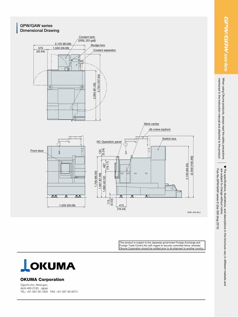
GPW/GAW seriesDimensional Drawing
2,73
4 (1
07.6
4)
2,06
4 (8
1.26
)
1,550 (59.06)575(22.64)
2,125 (83.66)
Coolant tank(200L [53 gal])
Sludge box
Coolant separator
Unit: mm (in.)
1,08
0 (4
2.52
)48
7(1
9.17
)
1,56
7 (6
1.69
)13
3(5
.24)
115
(4.5
3)
1,70
0 (6
6.93
)
415(16.34)
Switch box
Jib crane (option)
(2,5
50 [1
00.3
9])
NC Operation panel
Work center
Front door
1,550 (59.06)
2,15
0 (8
4.65
)
� The sp
ecifications, illustrations, and d
escriptions in this b
rochure vary in different m
arkets and
are subject to change w
ithout notice.P
ub.N
o.GP
W/G
AW
series-E-(2a)-300 (A
ug 2015)
When using O
kuma p
roducts, alw
ays read the safety p
recautionsm
entioned in the instruction m
anual and attached
to the prod
uct.
Oguchi-cho, Niwa-gun,Aichi 480-0193, JapanTEL: +81-587-95-7825 FAX: +81-587-95-6074
This product is subject to the Japanese government Foreign Exchange and Foreign Trade Control Act with regard to security controlled items; whereby Okuma Corporation should be notified prior to its shipment to another country.