co2 recovery - biothec · 2 gas processing from the asco 2 stack gas recovery system is co...
TRANSCRIPT

ASCO CARBON DIOXIDE LTD | Industriestrasse 2 | CH–8590 Romanshorn | T +41 71 466 80 80 | ascoco2.com
Version 3.2 (09/17)
ASCO’s innovative ASCOSORB CO2 Stack Gas Recovery Technology turns your vent flue gas into a usable and profitable source of CO2.
CO2 gas won by a ASCO Stack Gas Recovery System is a by-product of flue gas production from boilers as well as from other flue gas sources offering an economic CO2 source to any CO2 consumer or reseller. ASCO, as a provider of complete CO2 solutions, offers CO2 Stack Gas Recovery Systems with various capacities.
The revolutionary ASCOSORB CO2 Stack Gas Recovery Technology features the following key benefits:
• Reliable and economic source of CO2 to the end user as opposed to self burning processes or purchasing liquid CO2
• The ASCOSORB Technology brings to the ASCO CO2 Stack Gas Recovery Plant tremendous reduction in total energy usage offering greatly reduced OPEX: only approx. 0.9 MWth / MT produced CO2
• The ASCOSORB Technology brings to the CO2 stack gas recovery plant innovations such as reduced solvent consumption again contributing reduced operating cost to the already reduced OPEX
• The specially formulated ASCOSORB solvent utilized with the ASCO CO2 Stack Gas Recovery System is re-sistant to any level of oxygen typical of flue gas sources allowing greater system efficiencies and longevity of the plant
• Liquid CO2 quality produced by an ASCO CO2 Stack Gas Recovery System meets specifications of ISBT, food and beverage, and customer final liquid quality specifications
• ASCO CO2 Stack Gas Recovery Systems offer a capacity range from 285 to 11'000 kg/h (24250.84 lb/h)
CO2 Recovery
ASCO CO2 Stack Gas Recovery Systems
ASCO’s CO2 Stack Gas Recovery Technology extracts nearly the total volume of CO2 gas content in flue gas streams. Key is the specially formulated ASCOSORB extraction solvent which provides the CO2 Stack Gas Recovery Plant with reduced OPEX as a result of its CO2 gas extraction and loading capability com-pared to other competitive solvent mixtures. This technology not only offers the end user a reliable CO2 source but as well considered by many a green approach to the overall concept to CO2 gas recovery. Combined with the specially formulated ASCOSORB Solvent, the ASCO CO2 Stack Gas Recovery System utilizes stainless steel process towers and pumps to ensure long and effective equipment life and reliable perfor-mance for years to come.
ASCO CARBON DIOXIDE LTD | Industriestrasse 2 | CH–8590 Romanshorn | T +41 71 466 80 80 | ascoco2.com
Version 3.2 (09/17)
ASCO CO2 Stack Gas Recovery Systems: Features
Feature Benefit
Stainless steel construction Long plant longevity
Low energy consumption Low OPEX
Integrated amine recovery Contributing to the already reduced OPEX
High CO2 extraction Low carbon foot print
Retrofits easily to existing CO2 production plants
Modernize your existing plant by eliminating fuel burning and saving up to 70 % pro-duction costs.
Flexible layout Compact, modular component design means fast and easy installation and provides an economical use of available space, covering a variety of different layouts.
Inline scrubber water recirculation and treatment system
Designed to handle all the process scrubbing water, this system recycles, neutralises and sheds the process heat from the water all in one circuit. This significantly reduces the volume of water discharged to drain, providing an economical and environmen-tally friendly water system.
Process towers location Option of indoor or outdoor installation of all process towers allows flexibility of layout in a variety of different situations. Outdoor location also reduces the required weather protection for the system.
Oilfree CO2 compressor Specially designed for use with CO2 gas, the oilfree compressor means there is no possibility of CO2 contamination with oil.
High pressure stainless steel purifier
Longer residence time provides ultra-efficient NOx and H2S removal.
Carbon filter A high capacity carbon filtration column is installed in the CO2 gas inlet line to the liquefier, to provide further assurance of pure and odour-free CO2.
Centralized control panel Automatic plant operation and visual display (HMI) provide one touch read-outs of process data from a centralized position.
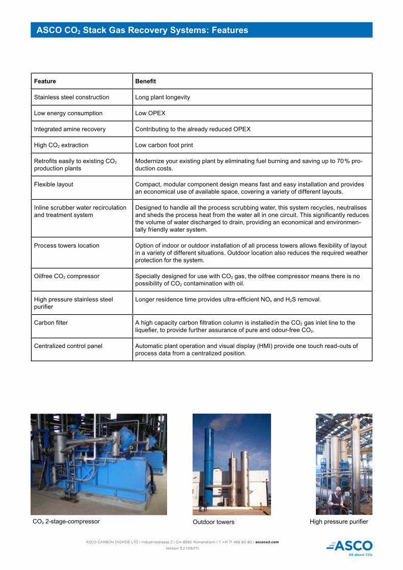
High pressure purifierOutdoor towersCO2 2-stage-compressor
ASCO CARBON DIOXIDE LTD | Industriestrasse 2 | CH–8590 Romanshorn | T +41 71 466 80 80 | ascoco2.com
Version 3.2 (09/17)
General process description
Flue gas from boiler exhausts (be it existing, new or even power generators) contain combustion products like CO2, water vapor, N2, O2, CO, and possibly SO2 depending on the fuel being used. This flue gas, under the ASCOSORB process, is first cooled and treated for SO2 effectively rendering a flue gas to a proper operating temperature and reaching an acceptable level of SO2 prior to entering the ASCOSORB process of CO2 Gas extraction.
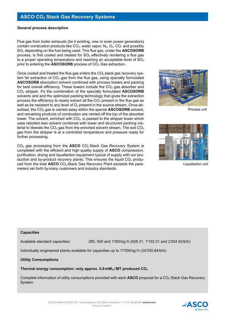
Once cooled and treated the flue gas enters the CO2 stack gas recovery sys-tem for extraction of CO2 gas from the flue gas, using specially formulated ASCOSORB absorption solvent combined with process towers and packing for best overall efficiency. These towers include the CO2 gas absorber and CO2 stripper. It’s the combination of the specially formulated ASCOSORB solvents and and the optimized packing technology that gives the extraction process the efficiency to nearly extract all the CO2 present in the flue gas as well as be resistant to any level of O2 present in the source stream. Once ab-sorbed, the CO2 gas is carried away within the special ASCOSORB solvent, and remaining products of combustion are vented off the top of the absorber tower. The solvent, enriched with CO2, is passed to the stripper tower which uses reboiled lean solvent combined with tower and structured packing ma-terial to liberate the CO2 gas from the enriched solvent stream. The exit CO2 gas from the stripper is at a controlled temperature and pressure ready for further processing.
CO2 gas processing from the ASCO CO2 Stack Gas Recovery System is completed with the efficient and high quality supply of ASCO compression, purification, drying and liquefaction equipment typical of supply with our pro-duction and by-product recovery plants. This ensures the liquid CO2 produ-ced from the total ASCO CO2 Stack Gas Recovery Plant exceeds the para-meters set forth by many customers and industry standards.
ASCO CO2 Stack Gas Recovery Systems
Capacities
Available standard capacities: 285, 500 and 1'000 kg / h (628.31, 1'102.31 and 2'204.62 lb/h)
Individually engineered plants available for capacities up to 11'000 kg / h (24'250.84 lb/h)
Utility Consumptions
Thermal energy consumption: only approx. 0.9 mWth / MT produced CO2
Complete information of utility consumptions provided with each ASCO proposal for a CO2 Stack Gas Recovery System.
Liquefaction unit
Process unit

ASCO CARBON DIOXIDE LTD | Industriestrasse 2 | CH–8590 Romanshorn | T +41 71 466 80 80 | ascoco2.com
Version 3.2 (09/17)
ASCO CO2 Stack Gas Recovery Systems
Standard Layout Proposal (dimensions in mm)
Capacity A B C D E F G
285 kg/h(628 lb/h)
10'000(394 in)
10'000(394 in)
3'500(138 in)
6'160(243 in)
3'000(118 in)
6'000(236 in)
14'740(580 in)
500 kg/h(1'102 lb/h)
10'000(394 in)
10'000(394 in)
4'900(193 in)
6'160(243 in)
3'000(118 in)
6'000(236 in)
14'740(580 in)
1'000 kg/h(2'205 lb/h)
10'000(394 in)
15'500(610 in)
4'900(193 in)
6'160(243 in)
3'000(118 in)
6'000(236 in)
15'140(596 in)
1. Caustic dosing unit 2. Scrubber tower 3. Absorber tower 4. Stripper tower 5. Process unit 6. CO2 compressor 7. Purifier tower 8. Purifier recharge unit 9. Drier filter set 10. Liquefier 11. Control panel 12. Cooling tower (optional) 13. CO2 storage tank (optional)
Subject to technical changes / improvements