coco-cola maintaince and training(asebi)
TRANSCRIPT

MaintenanceTraining
This training is intended for Maintenance personnel

Parts of Machine
Computer CabinetInspection Head

Base Strobe Assembly
Circuit Breaker Panel
Diffuser Glass Motor
UPSGearbox
Starwheel Motor Power
Supply
Base Cabinet Front Door
PLC Interface
Vacuum Venturi
with Tank
UPS Batteries

Starwheel Motor Vacuum Venturi Pump
RejectValve
Base Cabinet Front DoorVacuum
Surge Tank
Power Supply Drawer

Controller forReject Conveyor
Motor
Reject Conveyor Motor ControllerStarwheel Motor Power Supply
UPS

Base Cabinet Drawer
Main PowerTransformer
Base StrobeAir Filter
StarwheelSystem
Air Filter
StarwheelVacuum
Filter
StarwheelReject Pressure
Regulator
Bottom/DiffuserBlow-OffPressureRegulator
MachinePressureRegulator
Base Cabinet Back Door

Cabinet Drawer

Maintenance panel
Main Regulator Air
Regulator Base blow off
Regulator Reject Pressure
Machine Input Pressure min. 80PSIBottom blow off press.
Starwheel cleaning pressureReject pressure

Airfilter Panel
! ! !

Cabinet Transformer 115VAC

UPS Card and Batteries

Motors for Diffuser and Brush Drive

Diffuser or Rotating Glass
Test BottleSensor
Body Belt
Neck Belt
Airknife
Rotating Glass Drive
Water Drip Valve

Base Strobe Lamp
Input voltages LED 1000V and 280V

Reject Valve

Vacuum Buffer Tank

Circuit Breakers and Voltage monitor

PLC interface

Computer compartment

Hard Disk
CPU Card
Alacron Board forBase, ISW, Finish & Thread
Inspection Alacron Board forOSW Inspection
Finish and ThreadCamera
Inner SidewallCamera
Base Camera
IR-RLD Sensor
IR-RLD Board
ServoController
KeyboardController Card
(KCC)Camera Breakout
Board
Servo Motorfor Zoom and
Brightness
Inspection Head
Reject Verifier
Finish Strobe (LED) Power +48V Supply
Cooling System
Computer Cage Power

Finish interface card

Camera Breakout board

Computer Card cage

Reject verifier Sensorlocated underneath computer card cage

Hard Drivelocated on side of computer card cage

Lenses under inspection head
IR-RLDBaseISWLens
Test Bottle Sensor
Neck Belt
Finish lens

Reject Verifier
Reject Verifier

Touchpad – LCD Display

Starwheel

Starwheel Area
SealringValve plate

Valve Plate
Purge 5-7 psi
Vacuum
Reject PortVacuum/Pressure
Vacuum
Atmosphere

Guide rails (wearstrips)

Upper Starwheel Position
About 1-2mm distance between Bottle and Starwheel plate. To be adjusted with spacer underneath starwheel plate
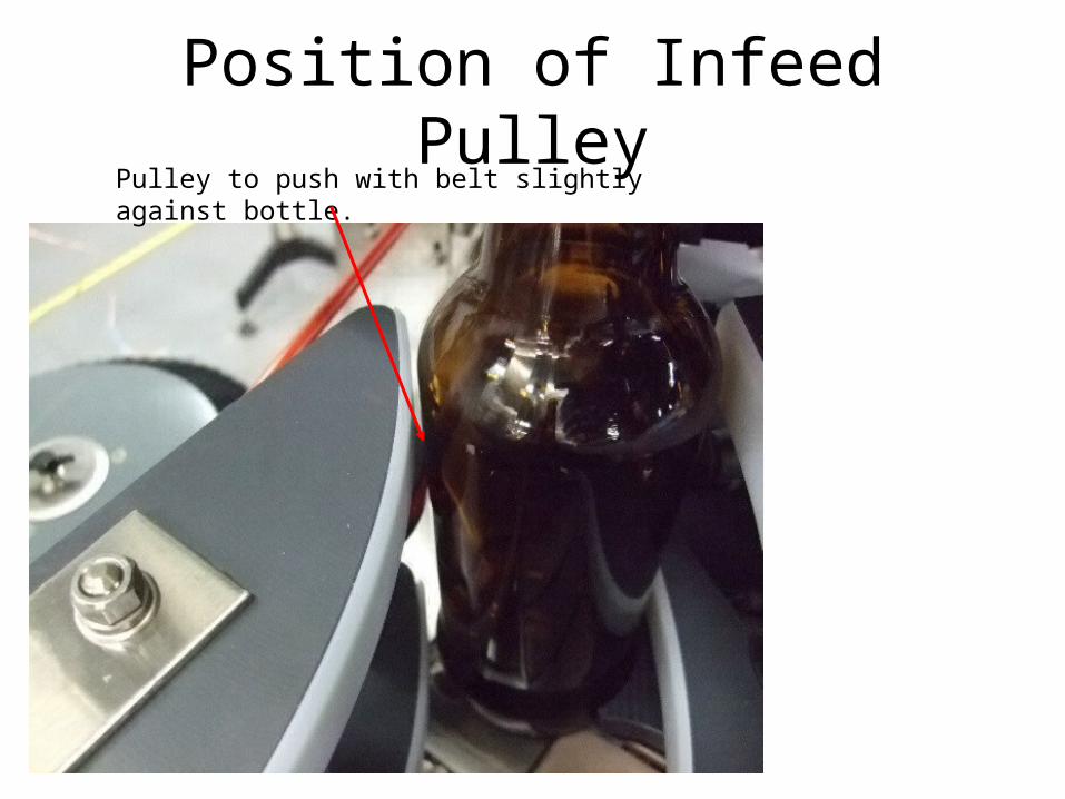
Position of Infeed PulleyPulley to push with belt slightly against bottle.

Deadplate

Base Blow off Air Knife

Air knife

Adjustment of Base Blow off Valve
Loosen bolts and move valve
Adjust airflow

Conveyor encoder

Drive sprocket of encoder

Sonic 1 to detectMissing Bottle
Sonic 2 to closegaps in front of
the Outersidewall
OverheightBottle and
Down BottleSensor
Infeed Sonics

Infeed SonicsClose up
Sonic Transmitter and Receiver

RF-RLD Sensor
RF-RLD Sensor

Position of RF sensors to bottle
2-3mm space

Adjustment of RF sensor blocks
Adjust the RF Guides, so the bottles don‘t hit against guide plates

Adjustment of RF sensor blocks

Mirror
DigitalOSW
Camera
ElevatorMotor
ServoController
Servo Motors
Fuse for ElevatorMotor
Outer Sidewall Camera Box
Freznel Lens
Servo / Camera Power Supplies
Heater

Light Panel
Cooling Fan
Outer Sidewall Light Panel Box
Intake Air Filter

OSW camera elevation system
Drive motor for elevation system

OSW digital camera

OSW servo controller

OSW infeed guide rails

OSW rotator guides

OSW rotator guides
Rotation OV2 OSW

PowerPower Switch-When powering down the UPS will keep the unit up for about 1 minute.

E-Stops
E-stopPress in – FreewheelPull out – Hard Break

Door Switch
Door Switch

Alarm
Warning
Ready
Test Bottle Request
System Power is On
Beacon Light Tower
This same color scheme is used on all OMNI Screens in lower bottom right corner.

24 VDC Power supply for Computer. On backside of UPS card bracket
115VAC Input
24VDC output

DC-DC converter card

LED‘S DC-DC converter card

PS 4
PS 1
Line Control Module(LCM)
XFMR 2
PD 2
PS 3
PS 5
XFMR 1
Base Cabinet Drawer
HV Rectifier

Sensor connection blocks
Sensor blocks: SB1 and SB3 outside base cabinet. SB2 inside base cabinet

Brake Out (System Ready)
External Brake
Run Out
PLC Interface
Encoder
Fuse
Downstream Gap
Reject Throughput (PIN)
Reject Inhibit
(not recommended)
Jam
Upstream Down Bottle
Downstream Down Bottle
Spare
PLC Outputs Inputs38997

UPS card and batteries

Theory/Functionality:
The OV-II UPS is not a typical AC UPS.The OV-II UPS is a DC UPS whose sole purpose is to switch 24VDC from the power supply in the Base
Cabinet (which is killed when the main power switch is thrown) to the 24VDC battery for a period of one minute to allow Windows to have time to properly
shut down.

The Lead-Acid 24VDC UPS battery is charged with the 30VDC power supply that is mounted in the
Base Cabinet. CB-11, the breaker for this supply, is connected directly to the in-coming 220VAC line to allow charging to take place regardless of the state of the main power switch. The power for this circuit
is not subordinate to the main Power Switch.
UPS Battery

LCM on cabinet drawer
LCM
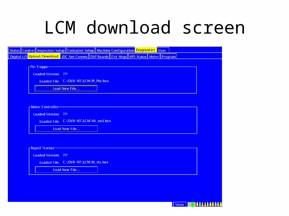
LCM download screen

1
EncoderMotor
Starwheel
Reference position « 1 »From « Pin 1 Offset »
Vacuum Tubes

Reject conveyor

Light Source (Strobe Lamp)
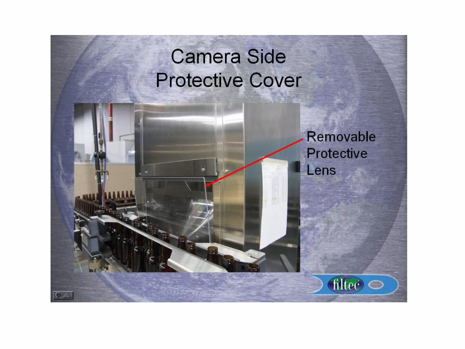
SemitransparentMirrors
Protection windows
IRBase
(Caméra)ISW
(Caméra)
Finish(Caméra)
Thread(Caméra)
Rotating glass
Diffuser glass (Brightfield Option)
Option
IR RLD detection
LED Strobe Lamp

IR Detection
Light source
IR
Rotating glass
Principle of function
Infra Red photocell
Lens system to adjust brightness and zoom
Residual liquid inside bottle
BT#3

Principal of function for Base
Light source
Semitransparentmirrors
Protection window and lens
Base(Caméra)
Rotating glass
Diffuser lens and polarization filters

5 3
Base
0M
iddl
e R
im
Cen
terO
uter
Rim
035
CenterMiddle Rim
Outer Rim
Camera Image
Desciption of Inspection zones

Principle of function
Semitransparent mirrors
Protection window and lens
Rotating glass
Diffuser lens and polarization filters
ISW(Caméra)
Normal mirror

5 3 0M
iddl
e
Bot
tom
Upp
er
035
Middle
Upper
Bottom
ISW

Principle of function
Finish(Caméra)
Light source
Parabolic mirrors

Caustic Detection (RF-RLD)OSW
OMNI II
Sensor position
Bottle with no caustic
Transmitter RF
ReceiverRF
Bottle with caustic
BT#4

“OSW”
Principle of OSWOSW (Caméra)
Light Source
Caméra
Mirror

Principel of rotation OSW
Lower GuidesNeck
Guides

Principel of OSW inspection
Lower Guides
Neck Guides
A B C
Defect on bottle « A »
P1 P2 P3 P4 P5

Lower guides
Neck guides
P1
A B C
Defect is detected in window 2
#4
#3
#2
#1
P2 P3 P4 P5

Lower Guides
Neck Guides
A B C
#4
#3
#2
#1
P1 P2 P3 P4 P5

Lower Guides
Neck Guides
A B C
#4
#3
#2
#1
P1 P2 P3 P4 P5
Other defect in new bottle on zone 4

Base Camera/Display
3000 - 3500

Base Zone Setup

Base Algorithms

Calibration Procedures
Base Inspection Setup

Zone Setup – Screen

Algorithm – Screen

Masks

Inner Sidewall
• ISW Calibration procedures• Base-Inner sidewall parameter description
s

Finish Inspection

aCb
A Sector
Finish

Finish Locator DiagramWidth = 6Light = 120
Width = 6Light = 120
Width = 6Light = 120
Width = 5Light = 160
Width = 4Light = 120
Width = 8Light = 200
Width = 5Light = 70
Width = 5 Light = 120
Finder Track Width = 5Minimum Track Threshold = 80
Tracking WindowWidth
Locator Positions


Tracking Centering – Screen

Lane AWill not allow Sector Average Size light level to drop below this value
Increasing this value makes it easier to detect object. DO NOT EXCEED 50!!
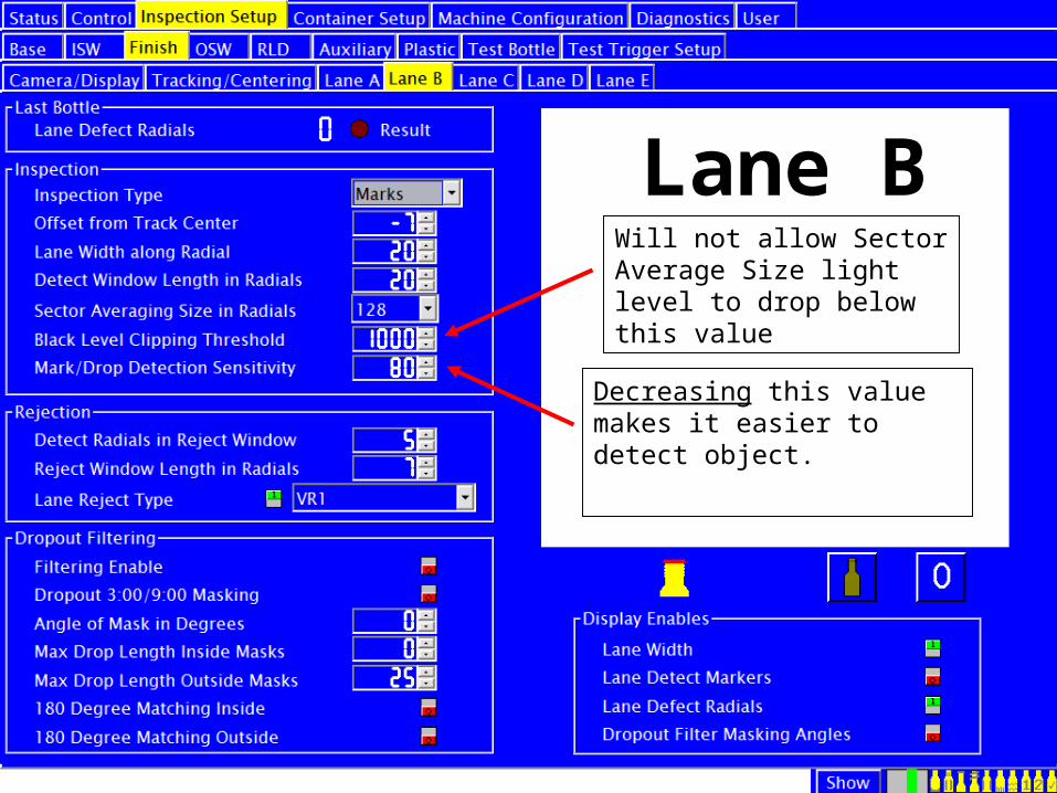
Lane BWill not allow Sector Average Size light level to drop below this value
Decreasing this value makes it easier to detect object.

Finish Setup procedures
• Finish Setup

Camera/Display

Horizontal Registration

Vertical Registration
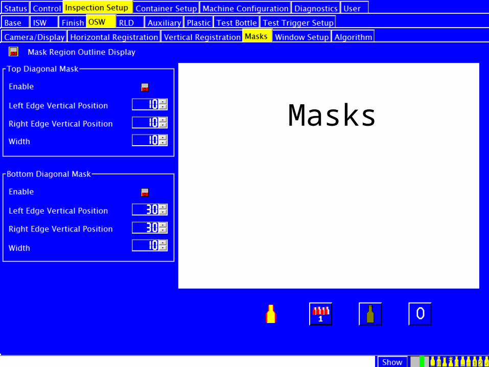
Masks

Window Setup

Algorithm

OSW setup
• OSW setup

Setup IR & RF RLD
Base Zoom - 10


Line Control – Screen


Test Bottle Program

Test Bottles are run from this
Screen
Start Test Here

Test is running
Time to complete test and bottles to go
Next Auto Start
Time to start after auto start
Running Test Bottle Program

Results from test bottle

Test bottleBottle Insertion
To change either selection below requires maintenance level password access.
• In order– Bottles must be run in order
• This is the recommended method.• Random Order
– Bottles can be run in any order. The machine will automatically resort the order and show results.

Bottle Changeover Screen

Changeover steps

Changeover cautions
• When seating starwheel verify valve plate is clean.
• Verify starwheel is seated correctly.• Tighten the starwheel locking handle is
extremely tight.

Bottle Changeover
All parts associated with the changeover are color coded to aid in this changeover process.

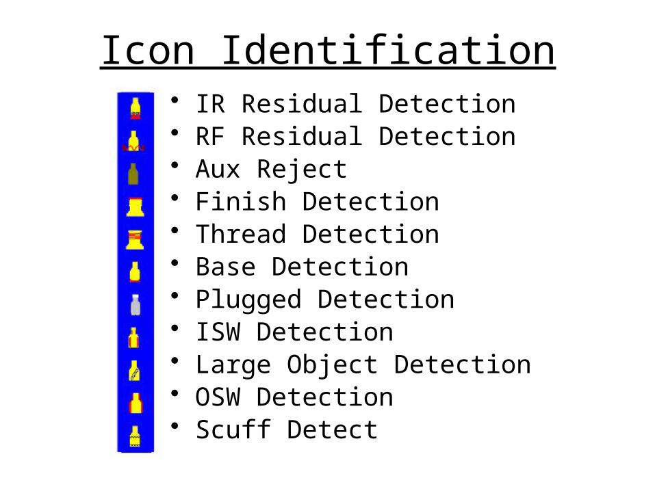
Icon Identification• IR Residual Detection• RF Residual Detection• Aux Reject• Finish Detection• Thread Detection• Base Detection• Plugged Detection• ISW Detection• Large Object Detection• OSW Detection• Scuff Detect