code of practice for temporary traffic management (copttm
TRANSCRIPT

Traffic Control Devices Manual Part 8 Code of practice for temporary traffic management (CoPTTM) manual number: SP/M/010
Section B
© NZ Transport Agency
www.nzta.govt.nz
Fourth edition, Amendment 4 of Code of practice for temporary traffic management
Date of issue: February 2017
Effective date: 1 April 2017
ISBN 978-0-478-40772-3 (print)
ISBN 978-0-478-40773-0 (online)
Copyright information
This publication is copyright © NZ Transport Agency. Material in it may be reproduced for personal or in-house use without formal permission or charge, provided suitable acknowledgement is made to this publication and the NZ Transport Agency (NZTA) as the source. Requests and enquiries about the reproduction of material in this publication for any other purpose should be made to: NZ Transport Agency Private Bag 6995 Wellington 6141
The permission to reproduce material in this publication does not extend to any material for which the copyright is identified as being held by a third party. Authorisation to reproduce material belonging to a third party must be obtained from the copyright holder(s) concerned.
Disclaimer
The NZTA has endeavoured to ensure material in this document is technically accurate and reflects legal requirements. However, the document does not override governing legislation. The NZTA and its employees and agents involved in the preparation and publication of this document do not accept liability for any consequences arising from the use of this document. Users of this document should apply and rely upon their own skill and judgment, and should not rely on the manual's contents in isolation from other sources of advice and information. In applying their own skill and judgment, the standards of safety and serviceability explicitly required or implied by this manual shall not be reduced. If the user is unsure whether the material is correct, they should make direct reference to the relevant legislation or regulations and contact the NZTA.
More information
Published 2013
ISBN 978-0-478-40772-3 (print)
ISBN 978-0-478-40773-0 (online)
NZ Transport Agency
Traffic control devices manual part 8 CoPTTM Section B – Page i 4th edition, February 2017
Section B – Equipment
B1 Signs (including stands and supports) 1
B1.1 Introduction 1
B1.2 General 1
B1.3 Sign standards 2
B1.4 Signs used at worksites 6
B2 Delineation devices 28
B2.1 General 28
B2.2 Colour 29
B2.3 Retro-reflectivity 29
B2.4 Dimensions 30
B2.5 Device durability 32
B3 High visibility garments 33
B3.1 Material compliance 33
B3.2 Logos 34
B3.3 Garment compliance 34
B3.4 Garment design 35
B3.5 Garment durability 46
B3.6 Optional illuminated attachments 46
B4 Logos, names and trademarks 48
B5 Portable traffic signals 49
B5.1 Single-lane signalised alternating flow 49
B5.2 Types of operation 52
B5.3 Timing of signal displays 53
B6 Safety fences 57
B7 Barricades 59
B8 Horizontal arrow boards and light arrow system 60
B8.1 General 60
B8.2 Light arrow system (LAS) 60
B8.3 Horizontal arrow boards 62

NZ Transport Agency
Traffic control devices manual part 8 CoPTTM Section B – Page ii 4th edition, February 2017
B9 Advance warning variable message sign (AWVMS) 65
B10 Mobile variable message sign (VMS) 67
B11 Truck-mounted attenuator (TMA) 69
B11.1 Introduction 69
B11.2 Rear panel of attenuator vehicle 70
B12 Temporary road safety barriers 73
B13 Temporary speed humps 77
B14 Warning systems 78
B14.1 Flashing beacons 78
B14.2 Xenon warning lights 80

NZ Transport Agency B1 Signs
Traffic control devices manual part 8 CoPTTM Section B – Page 1 4th edition, February 2017
B1 Signs (including stands and supports)
B1.1 Introduction
This part describes all temporary works signs and any relevant regulatory signs that apply to temporary traffic management (TTM).
The numbering of signs for TTM is in accordance with the Land Transport Rule: Traffic Control Devices 2004 (TCD Rule) and the Traffic sign specifications.
This part displays some general detail about sign features such as colour and size, it references back to the Traffic sign specifications for detailed measurements.
The TCD rule now allows for a minimum width supplementary sign of 900mm. Previously these signs were manufactured to a 950mm standard. The 950mm signs are not obsolete and may continue to be used while fit for purpose.
B1.2 General
TTM signs are set out at worksites to:
• provide advance warning • direct and protect road users, and road workers • notify road users when they are safely through a worksite.
All TTM signs must comply with the NZTA’s:
• TCD Rule • CoPTTM.
Signs used in TTM fall into two categories:
• temporary warning signs • regulatory signs.

NZ Transport Agency B1 Signs
Traffic control devices manual part 8 CoPTTM Section B – Page 2 4th edition, February 2017
Level 1
750mm
300mm
900mm
B1.3 Sign standards
All signs must comply with the requirements in New Zealand Standard 5414:1977 Specification for the construction of traffic signs (NZS 5414:1977) and Australian and New Zealand Standard 1906.1:2007 Retro-reflective materials and devices for road traffic control purposes - Retro-reflective sheeting (AS/NZS 1906.1:2007), except where modified by CoPTTM. Where requirements are duplicated, AS/NZS 1906.1:2007 must take precedence over NZS 5414:1977.
All sign faces (temporary and regulatory) must have retro-reflective material backgrounds. Retro-reflective material must only be applied to substrates approved by the manufacturer and application methods must comply with the manufacturer's recommendations.
Most temporary warning signs must have retro-reflective fluorescent orange backgrounds. For exceptions, refer to the TCD Rule, schedule 1.
B1.3.1 Sign standards on level LV and level 1 roads
B1.3.1.1 Warning signs
All signs must comply with the dimensions and facings (retro-reflective, fluorescent orange backgrounds) detailed in the TCD Rule, schedule 1.
Typically level 1 signs are used on level LV and level 1 roads.
The larger level 2 and 3 signs may be used at the road controlling authority’s (RCA) discretion or where required specifically in CoPTTM.
The minimum size for a diamond-shaped sign is 750mm x 750mm.
The minimum size for a supplementary plate with a single line is 900mm x 300mm.
The minimum size for a supplementary plate with a double line is:
• 900mm x 500mm for any T1A supplementary plate
• 900mm x 450mm for any T2A supplementary plate
B1.3.1.2 Regulatory signs
The minimum size for a regulatory sign is 750mm diameter. However, 600mm diameter signs may be used for mobile operations.
900mm
T1A=500mmT2A=450mm

NZ Transport Agency B1 Signs
Traffic control devices manual part 8 CoPTTM Section B – Page 3 4th edition, February 2017
Level 2 and Level 3
1200mm
850mm
White Class 1 Retro-reflective corners
B1.3.2 Sign standards on level 2 and 3 roads
B1.3.2.1 Warning signs
All signs must comply with the dimensions and facings (retro-reflective, fluorescent orange backgrounds) detailed in the TCD Rule, schedule 1.
The minimum size for a diamond-shaped sign must be 850mm x 850mm and it must be superimposed on a white 1200mm x 1200mm square-shaped backing board.
The minimum size for a level 2 and 3 supplementary or rectangular sign with a single line is 1200mm x 400mm.
400mm
1200mm
The minimum size for a level 2 and 3 supplementary or rectangular sign with a double line is 1200mm x 600mm.
600mm
1200mm
B1.3.2.2 Regulatory signs
The minimum size must be as stated in the table below.
Level 2 roads 1200mm diameter for regulatory speed (RS1) signs.
900mm diameter for all other regulatory signs.
750mm diameter for vehicle-mounted signs unless specified otherwise in CoPTTM.
Level 3 roads 1200mm diameter for all regulatory signs.
750mm diameter for vehicle-mounted signs unless specified otherwise in CoPTTM.
B1.3.2.3 900mm warning and regulatory signs for shoulders, medians and roadside areas
Where shoulders, medians and roadside areas will not accommodate a full size sign, a 900mm warning or regulatory sign including a speed limit sign may be used with the RCA’s permission.

NZ Transport Agency B1 Signs
Traffic control devices manual part 8 CoPTTM Section B – Page 4 4th edition, February 2017
B1.3.3 Non-standard, one-off or special signs
The words and symbols on existing signs are chosen from experience and are designed to maintain consistency.
Only those signs approved in the TCD Rule and listed in CoPTTM are to be used.
Signs for special purposes can be approved by the RCA. These must comply with the TCD Rule. The signs must comply with the following general temporary warning sign requirements:
• Signs must be symbolic rather than in words wherever possible. • Where permanent warning sign legends/symbols are adopted for TTM
purposes at worksites, the sign background must be specified as reflective orange rather than the retro-reflective yellow.
• Additional direction signs must comply with the usual format used by the RCA. Letter sizes and spacing must match those on permanent sign faces, and be related to the vehicle-approach speed at the sign location.
If a contractor considers the range of signs inadequate and a sign with a different legend is required, a request must be made to:
Senior Traffic and Safety Engineer (CoPTTM) NZTA National Office Private Bag 6995 Wellington 6141
Email: [email protected]
The NZTA will consider the request and notify the decision.

NZ Transport Agency B1 Signs
Traffic control devices manual part 8 CoPTTM Section B – Page 5 4th edition, February 2017
B1.3.4 Sign stands and supports
Sign stands and/or supports must be designed to ensure they:
• will not cause significant damage to a vehicle if struck by one • are stable under all reasonably expected weather conditions and air
turbulence from passing traffic, and • will not present a hazard to vehicles, including bicycles, after being
knocked or falling over, ie the sign’s support and stand must lie relatively flat with no part more than 150mm above the ground surface.
Sandbagging is an effective method of securing signs. Signs must not be secured by hanging a weight from any part of the sign. Concrete and heavy steel (truck wheel rims, welded water pipe, etc) must not be used as a base for signs.
Where ballast is used on a sign stand or base it must:
• be designed so that it cannot roll • be constructed from hessian, rubber or plastic bags containing a soft
granular material, and • be no higher than 300mm above ground level.
Sign bases must:
• be designed so they cannot roll • be able to be placed/disassembled to a height equal to or less than
150mm • be designed to break away from the rest of the sign support system on
impact.
Subject to application via a TMP and approval by the RCA median barrier brackets may be used to support TTM signs.
Note: When a sign on a barrier is removed, the bracket must also be removed.

NZ Transport Agency B1 Signs
Traffic control devices manual part 8 CoPTTM Section B – Page 6 4th edition, February 2017
B1.4 Signs used at worksites
For the full sign use policies and sign design details refer to the Traffic sign specifications.
All temporary warning and regulatory signs are available in either level 1 or level 2 and 3 sizes.
The following table only illustrates level 1 signs unless a sign is only available as a level 2 and 3 sign.
B1.4.1 Advance warning
Sign name Sign reference
Illustration Requirements for use
Road works
Levels LV and 1
T1A
This sign is erected at all attended worksites. The sign is also used at unattended worksites where there are hazards within 5m of the edgeline.
An authorised supplementary sign may be used.
Road works
Levels 2 and 3
T1B
Road works
1 or 2 km
T141
This sign is used to give advance warning of major long-term worksites on level 2 and level 3 roads where there is a probability that a traffic queue will form.
T142
This supplementary plate can be used as an alternative to the T141 when it is combined with a T1B sign.
It measures 1200mm X 450mm.
Road works
DELAYS POSSIBLE
1 or 2 km
T143
This sign is used to give advance warning of major long-term worksites on level 2 and level 3 roads where there is a probability that a traffic queue will form and that some delays are also likely.

NZ Transport Agency B1 Signs
Traffic control devices manual part 8 CoPTTM Section B – Page 7 4th edition, February 2017
Sign name Sign reference
Illustration Requirements for use
Road works
‘_’ km/h AHEAD
T144
This sign is a supplementary plate for an advanced warning sign. It gives notice of a temporary speed limit ahead. The speed shown must be the same as the temporary speed limit imposed at the worksite.
Supplementary plate size:
• level 1 roads 900mm x 450mm
• level 2 and 3 roads 1200mm x 600mm.
Road works
NEXT 1, 2, 3 or 4 km
T121
This supplementary plate is used with an advance warning sign to indicate the extent of the road works. The sign is used where any type of activity has resulted in a road surface inferior to that on the approaches and that extends for more than 1km.
It is to be used in conjunction with a T1A/B or any other advance warning sign.
Road works
NEW SEAL
TR31
This supplementary plate is used with a T1A/B sign to indicate sealing operations and a newly sealed surface while it is susceptible to damage by motor traffic.
It is used with a T1A/B advance warning sign.
Road works
WET TAR
T145
It is used to indicate bleeding of a completed seal, new or otherwise.
This supplementary plate may also be used as an alternative to the TR31 NEW SEAL supplementary plate.
It is used with a T1A/B advance warning sign.
Road works
Specialist mobile plant
T132
This supplementary plate indicates that there is a grader operating on the roadway or within 5m of the edgeline. It is to be used in conjunction with a T1A/B advance warning sign.
Where the maintenance operation is outside the roadway but within 5m of the edgeline the T132 sign may be erected to warn road users approaching on the affected side only. Where the maintenance operation is on the roadway T132 signs must be erected on both approaches to the worksite.
T133
This supplementary plate indicates that there is skid testing being performed on the roadway or within 5m of the edgeline.
It is to be used in conjunction with a T1A/B advance warning sign.

NZ Transport Agency B1 Signs
Traffic control devices manual part 8 CoPTTM Section B – Page 8 4th edition, February 2017
Sign name Sign reference
Illustration Requirements for use
Road works
Specialist mobile plant
T136
This supplementary plate indicates that there is a mower operating on the roadway or within 5m of the edgeline.
It is to be used in conjunction with a T1A/B advance warning sign.
T137
This supplementary plate indicates that there is a weed sprayer operating on the roadway or within 5m of the edgeline.
It is to be used in conjunction with a T1A/B advance warning sign.
Road works
ROAD MARKING
T134
This supplementary plate indicates that road marking is being carried out.
It is to be used in conjunction with a T1A/B advance warning sign or if used in a mobile road marking operation it may be used in place of a supplementary road works sign TV2.
Road works
ON SIDE ROAD
T135
This supplementary plate indicates that there is a worksite or hazard on a side road. The sign is used where the worksite or hazard is too close to the intersection to meet the visibility criteria for advance warning signs.
It is to be used in conjunction with T1A/B or T2A/B advance warning signs.
Road works
SHOULDER CLOSED
T138
This supplementary plate indicates that the shoulder is temporarily closed by some road works activity.
It is to be used in conjunction with a T1A/B advance warning sign.
Road works
SURVEYING
T139
This supplementary plate must be displayed when a survey party is actually on the roadway or within 5m of the edgeline.
It can be used in conjunction with a T1A/B or a T2A/B advance warning sign.
Road works
BRIDGE REPAIRS
T140
This supplementary plate indicates that maintenance activity is being undertaken on a bridge.
It is to be used in conjunction with a T1A/B advance warning sign.

NZ Transport Agency B1 Signs
Traffic control devices manual part 8 CoPTTM Section B – Page 9 4th edition, February 2017
Sign name Sign reference
Illustration Requirements for use
Hazard warning
Levels LV and 1
T2A
This sign denotes a hazard warning and must only be erected in combination with approved supplementary plates. Hazard warning
Levels 2 and 3
T2B
Hazard warning
FLOODING
T211
This supplementary plate is used wherever surface water on the roadway creates a hazard. A depth of a few centimetres can be dangerous.
It must be used in conjunction with a T2A/B advance warning sign.
Hazard warning
WASHOUT
T212
This supplementary plate is used wherever a portion of road has eroded or fallen away and reduced the road width available to traffic.
Edge marker posts or temporary delineation devices can be used to indicate the edge of the useable roadway.
It must be used in conjunction with a T2A/B advance warning sign.
Hazard warning
LINEMEN
T213
This supplementary plate is used when people or machines are working on overhead lines or poles within the road reserve.
It must be used in conjunction with a T2A/B advance warning sign.
Hazard warning
BLASTING
T214
This supplementary plate is used to indicate blasting operations in hand on or near the road and where there is a danger to road users from flying debris.
It must be used in conjunction with a T2A/B advance warning sign.
Manual traffic controllers (MTCs) using RP4/RP41 STOP/GO paddles together with TA2/TA21 must employ manual traffic control signs on all road approaches in conjunction with the T214 supplementary plate, to prevent traffic entering the danger area for the duration of each danger period.
NZ Transport Agency B1 Signs
Traffic control devices manual part 8 CoPTTM Section B – Page 10 4th edition, February 2017
Sign name Sign reference
Illustration Requirements for use
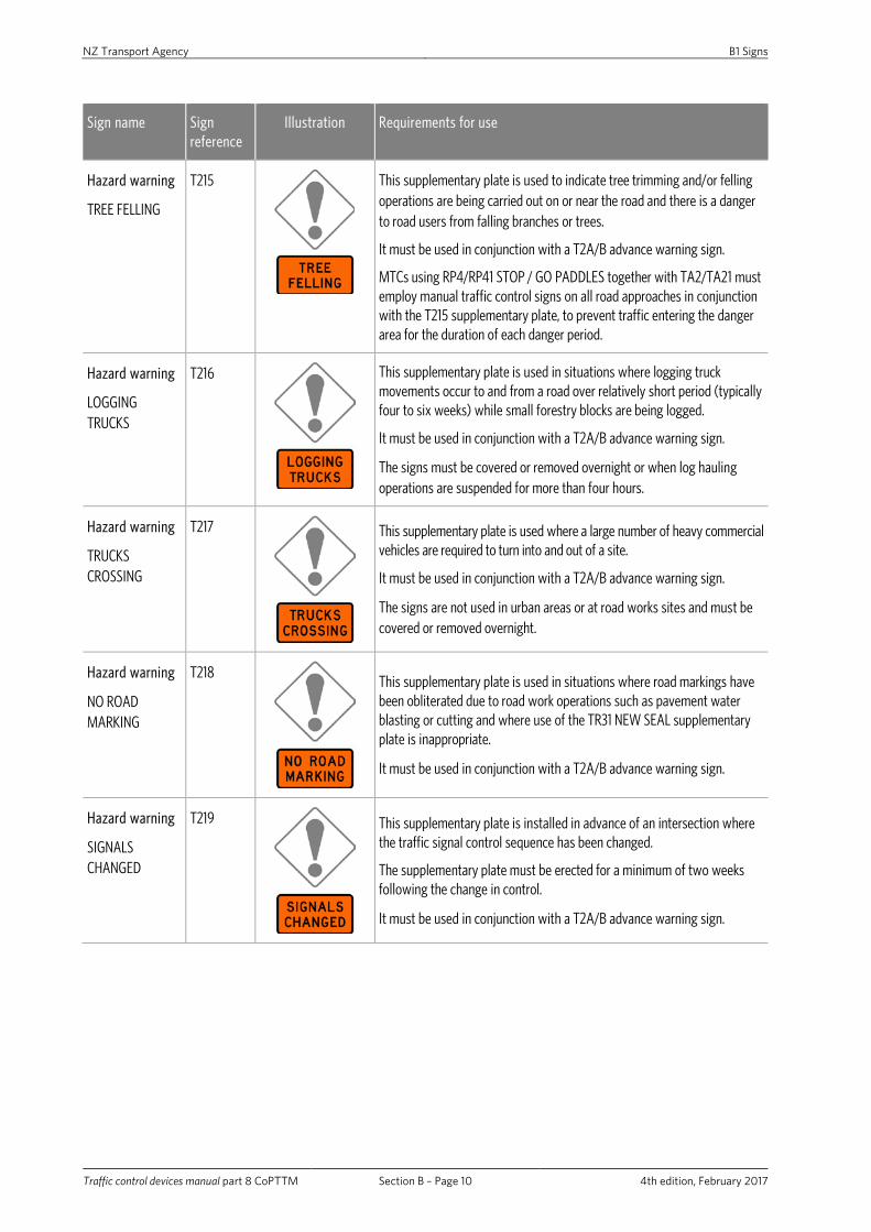
Hazard warning
TREE FELLING
T215
This supplementary plate is used to indicate tree trimming and/or felling operations are being carried out on or near the road and there is a danger to road users from falling branches or trees.
It must be used in conjunction with a T2A/B advance warning sign.
MTCs using RP4/RP41 STOP / GO PADDLES together with TA2/TA21 must employ manual traffic control signs on all road approaches in conjunction with the T215 supplementary plate, to prevent traffic entering the danger area for the duration of each danger period.
Hazard warning
LOGGING TRUCKS
T216
This supplementary plate is used in situations where logging truck movements occur to and from a road over relatively short period (typically four to six weeks) while small forestry blocks are being logged.
It must be used in conjunction with a T2A/B advance warning sign.
The signs must be covered or removed overnight or when log hauling operations are suspended for more than four hours.
Hazard warning
TRUCKS CROSSING
T217
This supplementary plate is used where a large number of heavy commercial vehicles are required to turn into and out of a site.
It must be used in conjunction with a T2A/B advance warning sign.
The signs are not used in urban areas or at road works sites and must be covered or removed overnight.
Hazard warning
NO ROAD MARKING
T218
This supplementary plate is used in situations where road markings have been obliterated due to road work operations such as pavement water blasting or cutting and where use of the TR31 NEW SEAL supplementary plate is inappropriate.
It must be used in conjunction with a T2A/B advance warning sign.
Hazard warning
SIGNALS CHANGED
T219
This supplementary plate is installed in advance of an intersection where the traffic signal control sequence has been changed.
The supplementary plate must be erected for a minimum of two weeks following the change in control.
It must be used in conjunction with a T2A/B advance warning sign.

NZ Transport Agency B1 Signs
Traffic control devices manual part 8 CoPTTM Section B – Page 11 4th edition, February 2017
Sign name Sign reference
Illustration Requirements for use
Hazard warning
SIGNALS NOT WORKING
T220
This supplementary plate is used when a traffic signal is not operational because of a fault or maintenance work.
The supplementary plate is not required when traffic signals are operating in the amber-flashing mode.
It must be used in conjunction with a T2A/B advance warning sign.
Hazard warning
NEW ROAD LAYOUT
T221
This supplementary plate is installed in advance of a change to the road, or an intersection, layout.
The supplementary plate must be erected for a minimum of two weeks following the change.
It must be used in conjunction with a T2A/B advance warning sign.
Hazard warning
TRAFFIC SURVEY
T222
This supplementary plate is used on the approaches to roadside traffic survey sites for the duration of survey.
It must be used in conjunction with a T2A/B advance warning sign.
When a T222 supplementary plate is used it must be augmented with a TA21 PLEASE STOP ON REQUEST plate and a TG31 THANK YOU plate is to be erected downstream of the survey site.
Hazard warning
Vulnerable road user event
T227
This supplementary plate is used for events involving cyclists.
This supplementary plate is to be erected on a stand, as for static operations, to warn road users of the event.
It must be used in conjunction with a T2A/B advance warning sign.
T228
This supplementary plate is used for events involving runners.
This supplementary plate is to be erected on a stand, as for static operations, to warn road users of the event.
It must be used in conjunction with a T2A/B advance warning sign.
T229
This supplementary plate is used for events involving walkers.
This supplementary plate is to be erected on a stand, as for static operations, to warn road users of the event.
It must be used in conjunction with a T2A/B advance warning sign.

NZ Transport Agency B1 Signs
Traffic control devices manual part 8 CoPTTM Section B – Page 12 4th edition, February 2017
Sign name Sign reference
Illustration Requirements for use
Hazard warning
ACCIDENT
T223
This supplementary plate is to be used whenever any traffic management measures are implemented at a crash site.
It must be used in conjunction with a T2A/B advance warning sign.
Hazard warning
FIRE
T224
This supplementary plate is used whenever fire fighting operations and/or drifting smoke presents a hazard to normal traffic operations.
It must be used in conjunction with a T2A/B advance warning sign.
Hazard warning
Vulnerable road users ahead
T230
This supplementary plate is used for long distance events involving cyclists.
The supplementary plate is to be erected on pilot vehicles accompanying the event to warn approaching and following drivers that there are cyclists on the road ahead.
It must be used in conjunction with a T2A/B advance warning sign.
T231
This supplementary plate is used for long distance events involving runners.
The supplementary plate is erected on pilot vehicles accompanying the event to warn approaching and following drivers to indicate that there are runners on the road ahead.
It must be used in conjunction with a T2A advance warning sign.
Hazard warning
Vulnerable road users ahead
T232
This supplementary plate is used for long distance events involving walkers.
The supplementary plate is erected on pilot vehicles accompanying the event to warn approaching and following drivers to indicate that there are walkers on the road ahead.
It must be used in conjunction with a T2A advance warning sign.
Hazard warning
FUNERAL
T225
This supplementary plate may be used in advance of a site where it is likely that funeral activities will present a hazard to normal traffic operations.
It must be used in conjunction with a T2A/B advance warning sign.

NZ Transport Agency B1 Signs
Traffic control devices manual part 8 CoPTTM Section B – Page 13 4th edition, February 2017
Sign name Sign reference
Illustration Requirements for use
Hazard warning
FILM CREW
T226
This supplementary plate may be used in advance of a site where it is likely that film making activities will present a hazard to normal traffic operations.
It must be used in conjunction with a T2A/B advance warning sign.
Hazard warning
HIDDEN QUEUE
WG12
This supplementary plate may be used in advance of a site where queues of vehicles (which have been delayed by roadworks or a temporary event) occur in a situation where they are hidden by road curvature or alignment from approaching vehicles.
It is to be used in conjunction with a T2A/B advance warning sign.
Slips
Left
TR1L
This sign is used wherever slips or other fallen debris affects part of the roadway.
Slips
Right
TR1R
Slippery surface TR2
This sign is used where road construction or maintenance machines carry clay or other materials onto the roadway surface, which consequently may temporarily become greasy when wet.
A WR3/WR32 SLIPPERY SURFACE - WHEN WET permanent sign is used where other surface defects not of a temporary nature cause the road surface to become slippery when wet.

NZ Transport Agency B1 Signs
Traffic control devices manual part 8 CoPTTM Section B – Page 14 4th edition, February 2017
Sign name Sign reference
Illustration Requirements for use
Slippery surface
ICE/GRIT and WHEN FROSTY
TR21
This supplementary plate is used when grit or CMA is spread onto the roadway surface to combat ice.
It is to be used in conjunction with a TR2A/B advance warning sign.
Additional TR2A/B and TR21 signs, spaced no more than 2km apart, must be erected along sections of road when grit or CMA has been spread on the roadway surface.
Where several such sections of road occur in close proximity, the first TR2A/B sign and TR21 supplementary plate may be augmented with an additional supplementary plate NEXT ‘_’ km.
Where a TR2A/B and TR21 sign is to be erected near a WR3/WR31 SLIPPERY SURFACE - WHEN FROSTY permanent sign, it is to be located past the WR3/WR31 sign by approximately 20 to 50m and in such a position that both signs will be visible at the same time to an approaching road user.
Gravel surface TR3
This sign is used when a section of normally sealed road temporarily has a gravel surface.
Because this is a more specific warning than the T1A/B road works sign it is to be used in preference to that sign whenever the main hazard is a gravel surface.
The supplementary plate TR31 NEW SEAL is to be added as soon as the surface has been sealed.
Gravel surface NEW SEAL
TR31
This supplementary plate is to be used as soon as new sealing has been completed and must remain in position until all loose chip has been removed and new pavement markings have been installed.
It is to be used in conjunction with a TR3 advance warning sign.
Gravel surface SEAL REPAIRS
TR32
This supplementary plate is used for multiple seal repair patches along a section of road less than 1km in length.
It is to be used in conjunction with a TR3 advance warning sign.
Where the length of road under repair is greater than 1km the TR32 supplementary plate must be repeated every 1km. Where several such sections of road occur in close proximity the first TR32 supplementary plate may be augmented with a T121 NEXT ‘_' km supplementary plate.

NZ Transport Agency B1 Signs
Traffic control devices manual part 8 CoPTTM Section B – Page 15 4th edition, February 2017
Sign name Sign reference
Illustration Requirements for use
Stock – temporary Cattle/Sheep
TF1
These signs are used where driven stock crosses or travels short distances along the road at infrequent intervals (greater than two days) and in such a location as to cause a traffic hazard.
The signs should only be displayed when stock is actually within the road reserve.
When the frequency of stock movements is greater (on a regular daily basis - often perhaps several times a day) or, where the lack of fences, walls, etc. along the road reserve results in continual presence of stock on the road the WF12/11 STOCK signs are a better option.
TF2
ROAD WORKS TV2
This sign indicates that this vehicle is involved with an operation on the road.
It must be used in conjunction with a vehicle-mounted flashing amber beacon.
It must be mounted on the front of the lead pilot vehicle for all mobile operations.
ROAD INSPECTION
TV3
This sign must be used in conjunction with vehicle-mounted flashing amber beacons and must be mounted on the rear of any vehicle conducting road inspections.
Diverge TL1
This sign may be used within a site where traffic lanes in the same direction are required to pass either side of a hazard.
Note: TL1 signs must never be used for centre lane closures.
Uneven surface TR4
This sign is used where road surface deformation constitutes an additional hazard at a worksite.

NZ Transport Agency B1 Signs
Traffic control devices manual part 8 CoPTTM Section B – Page 16 4th edition, February 2017
B1.4.2 Direction and protection
Sign name Sign reference
Illustration Requirements for use
Speed limit
TEMPORARY
To be used with the following RS1 signs:
• 20km/h
• 30km/h
• 40km/h
• 50km/h
• 60km/h
• 70km/h
• 80km/h.
RS1/TG1
The TG1 temporary plate must be used in conjunction with RS1 regulatory speed signs to restrict traffic speeds at worksites to give protection to workers, the road surface and road structures in an emergency.
The temporary speed limit must be at least 20km/h less than the normal speed limit for that section of road.
On all roads, except Level LV roads, the TG1 signs must be gated (ie a sign on both sides of the road). Repeater TSLs are only required on the left hand side only at 400m intervals.
Level 1- 750mm minimum diameter for static operations.
TEMPORARY supplementary plate - minimum 900mm x 300mm (TCD rule allows a minimum of 800mm x 250mm. This size is not recommended as it will not fit stands).
Level 2 and 3 - 1200mm minimum diameter for static operations.
No right turn RD1R
These signs are used to stop traffic turning into a hazard area.
Level 1 - 750mm minimum diameter for static operations.
Level 2 - 900mm minimum diameter for static operations.
Level 3 - 1200mm minimum diameter for static operations. No left turn RD1L
ROAD CLOSED RD3
This sign can only be used after formal authorisation by the controlling authority that the road is closed to ordinary vehicular traffic for the purpose of facilitating road works or any other legitimate activity. RD3 signs must be augmented with T1A/B road works signs and TD-type detour direction indicator signs used to indicate the shortest alternative route with an adequate width and no height restrictions.
Level 1 - 750mm minimum diameter for static operations.
Level 2 - 900mm minimum diameter for static operations.
Level 3 - 1200mm minimum diameter for static operations.

NZ Transport Agency B1 Signs
Traffic control devices manual part 8 CoPTTM Section B – Page 17 4th edition, February 2017
Sign name Sign reference
Illustration Requirements for use
Keep left RD6L
RD6L and RD6L twin disc signs are used to indicate that drivers must pass to the left of an obstruction or that the traffic lane(s) shift to the left.
Where an RD6L sign on the centre line of a two-way two-lane road is likely to pose a hazard due to insufficient lane widths the alternative RD6L twin disc sign may be used, subject to the approval of the TMP by the RCA or delegated person.
Level 1 - 750mm minimum diameter for static operations.
Level 2 and 3:
• 900mm minimum diameter for static operations
• 1500mm for mobile operations in association with R3-13.3
• 750mm when used with TV4.
Keep right RD6R
RD6R signs are used to indicate that drivers must pass to the right of an obstruction or that the traffic lane shifts to the right.
Level 1 - 750mm minimum diameter for static operations.
Level 2 and 3:
• 900mm minimum diameter for static operations
• 1500mm for mobile operations in association with R3-13.3
• 750mm when used with TV4.
Twin disk RD6L TWIN DISC
(300mm diameter)
On level LV and level 1 roads where an RD6L sign on the centre line of a two-way two-lane road is likely to pose a hazard due to insufficient lane widths the alternative RD6L twin disc sign may be used, subject to the approval of the TMP by the RCA or delegated person.

NZ Transport Agency B1 Signs
Traffic control devices manual part 8 CoPTTM Section B – Page 18 4th edition, February 2017
Sign name Sign reference
Illustration Requirements for use
Truck-mounted attenuator (TMA) display
R3-13.3
The display, installed on a vehicle equipped with an attenuator used to protect activity being conducted on the road beyond the sign, provides warning and indicates which side of the vehicle drivers must pass.
This sign replaces W4-9 horizontal arrow board which is being phased out as the steady diagonal downward arrow in sign R3 -13.3 is better understood by drivers than the ‘moving’ horizontal arrow in sign W4-9.
This display consists of three parts:
• the red and white delineation
• the light arrow RD6T
• the blue disk and white arrow RD6L/R.
The RD6L/R disk must be 1500mm in diameter (±50mm).
These arrows must not point vertically.
Light arrow RD6T
Keep left/right single disk
RD6L/R
Single-lane give way
RP51
(priority single lane)
(750mm minimum diameter)
The sign is used where a two-lane two-way road has been reduced to a single lane through a worksite or by a temporary hazard.
The RP51 sign is combined with the RP22 supplementary plate
These signs must only be used on two-lane two-way roads with an AADT of less than 1000vpd.
RP51 sign must be used in conjunction with RP52 SINGLE LANE - PRIORITY and TL9 ONE LANE signs.
RP51 signs must be erected in advance of the single lane section of road and on the approach where drivers have the best visibility through the single section and hence are in the best position to assess whether they must give way to oncoming traffic or may proceed if the road is clear.
RP22
(supplementary GIVE WAY)
Single lane priority
RP52
(560mm x 625mm
minimum)
RP52 signs must be used in conjunction with RP51 SINGLE LANE - GIVE WAY and TL9 ONE LANE signs.
The sign is used where a two-lane two-way road has been reduced to a single lane through a worksite or by a temporary hazard.
This sign must only be used on two-lane two-way roads with an AADT of less than 1000vpd.
RP52 signs must be erected in advance of the single lane section of road and on the approach considered most appropriate for assigning the priority traffic movement.

NZ Transport Agency B1 Signs
Traffic control devices manual part 8 CoPTTM Section B – Page 19 4th edition, February 2017
Sign name Sign reference
Illustration Requirements for use
STOP ON RED SIGNAL
RP61
(600mm x 600mm)
When it is impracticable to mark a limit line on the road surface these signs are used to emphasise where drivers are to stop.
They may be used at temporary or part time traffic signals with unsealed approach roads.
The RP61 STOP ON RED SIGNAL sign must be mounted on the primary traffic signal pole immediately below the traffic signal head.
The RP62 STOP HERE ON RED SIGNAL sign must be mounted at the point where vehicles are required to stop.
STOP HERE ON RED SIGNAL
RP62
No stopping at all times
(urban and road works situations)
PN11
(350mm x 500mm
minimum)
These signs are used to prevent parking where parked vehicles could restrict traffic flows through a worksite or temporary hazard site.
Lane closed
Two-lane one-way road
TL2L
This sign is used when the left lane is closed on two-lane one-way carriageway.
A supplementary distance plate is used for signs on level 2 and level 3 roads.
TL2R
This sign is used when the right lane is closed on two-lane one-way carriageway.
A supplementary distance plate is used for signs on level 2 and level 3 roads.
Lane management supplementary
100m
200m
300m
400m
TLS
This supplementary distance plate is used to provide warning of approaching lane change, lane merge or lane shifts on level 2 and level 3 roads. This supplementary plate is used in conjunction with TL type signs.
The use of the TLS supplementary plate is mandatory where signs are required at specified distances in advance of the lane changes, merges or shifts.

NZ Transport Agency B1 Signs
Traffic control devices manual part 8 CoPTTM Section B – Page 20 4th edition, February 2017
Sign name Sign reference
Illustration Requirements for use
Lane closed
Three-lane one-way road
TL3L
This sign is used when the left lane is closed on three-lane one-way carriageway.
A supplementary distance plate is used for signs on level 2 and level 3 roads.
TL33
This sign is used when the right lane is closed on three-lane one-way carriageway.
A supplementary distance plate is used for signs on level 2 and level 3 roads.
Centre lane closed
Three-lane one-way road
TL31
This sign may be used for a centre lane closure on three-lane one-way carriageway, where the speed limit is 50km/h or less and vehicles are required to merge to the left.
This sign must not be used on level 2 or level 3 roads, any state highways or roads with a speed limit in excess of 50km/h. Refer subsection C8.2.9 Centre lane closures.
TL32
This sign may be used for a centre lane closure on three-lane one-way carriageway, where the speed limit is 50km/h or less and vehicles are required to merge to the right.
This sign must not be used on level 2 or level 3 roads, any state highways or roads with a speed limit in excess of 50km/h. Refer subsection C8.2.9 Centre lane closures.
Lane closed
Four-lane one-way road
TL4L
This sign is used when the left lane is closed on four-lane one-way carriageway.
A supplementary distance plate is used for signs on level 2 and level 3 roads.
TL4R
This sign is used when the right lane is closed on four-lane one-way carriageway.
A supplementary distance plate is used for signs on level 2 and level 3 roads.
Lane shift
Two-lane one-way road
TL5L
This sign is used on a two-lane one-way carriageway to indicate that the road ahead is temporarily shifted from its normal alignment to the left.
A supplementary distance plate is used for signs on level 2 and level 3 roads.
TL5R
This sign is used on a two-lane one-way carriageway to indicate that the road ahead is temporarily shifted from its normal alignment to the right.
A supplementary distance plate is used for signs on level 2 and level 3 roads.

NZ Transport Agency B1 Signs
Traffic control devices manual part 8 CoPTTM Section B – Page 21 4th edition, February 2017
Sign name Sign reference
Illustration Requirements for use
Lane shift
Three-lane one-way road
TL6L
This sign is used on a three-lane one-way carriageway to indicate that the road ahead is temporarily shifted from its normal alignment to the left.
A supplementary distance plate is used for signs on level 2 and level 3 roads.
TL6R
This sign is used on a three-lane one-way carriageway to indicate that the road ahead is temporarily shifted from its normal alignment to the right.
A supplementary distance plate is used for signs on level 2 and level 3 roads.
Merging traffic
Main road
TL71
This sign is used on level 2 and level 3 roads when one or more lanes on the main road are closed and the normal on ramp taper has been extended to the lanes remaining open to traffic.
A supplementary distance plate is used for signs on level 2 and level 3 roads.
Side road TL72
This sign is used on on-ramps to level 2 and level 3 roads when one or more lanes on the main road are closed.
A supplementary distance plate is used for signs on level 2 and level 3 roads.
Advance exit TL81
This sign is used on level 2 and level 3 roads when one or more lanes on the main road are closed and the normal off ramp taper has been extended to the lanes remaining open to traffic.
A supplementary distance plate is used for signs on level 2 and level 3 roads.
Exit direction TL82
This sign is normally only used on multi-lane divided carriageway roads where one or more of the main road lanes have been closed and an off ramp exit lane has been extended to meet the lane remaining open to traffic.

NZ Transport Agency B1 Signs
Traffic control devices manual part 8 CoPTTM Section B – Page 22 4th edition, February 2017
Sign name Sign reference
Illustration Requirements for use
One lane
Left side narrowing
TL9L
These signs must only be used on two-lane two-way roads with an AADT of less than 1000vpd where the road is effectively reduced to a single lane.
They are combined with a TL9S supplementary plate.
TL9L/R and TL9B signs must be augmented with RP51 single lane - give way signs and RP52 single lane - priority signs. One lane
Right side narrowing
TL9R
One lane
Both sides narrowing
TL9B
One lane
ONE LANE
TL9S
This supplementary plate is used to inform road users that the road ahead narrows to one lane.
It is to be used in conjunction with a TL9L/R/B sign.
Traffic signals
Temporary
TA1
This sign is normally only used on two-lane two-way roads to provide advance warning of temporary traffic signals at a worksite.
TA1 signs must be augmented with T1A/B ROAD WORKS signs and TG1 speed limit – TEMPORARY signs (30km/h or less).
Manual traffic control
TA2
This sign is used at worksites on two-lane two-way roads to provide advance warning of manual traffic control using RP4/RP41 STOP/GO paddles.
TA2 and TA21 signs must be augmented with T1A/B ROAD WORKS signs and TG1 speed limit - TEMPORARY signs (30km/h or less).
PLEASE STOP ON REQUEST
TA21
This sign is used in advance of the T222 TRAFFIC SURVEY sign and also may be used as a supplementary plate to the TA2 manual traffic control sign.
NZ Transport Agency B1 Signs
Traffic control devices manual part 8 CoPTTM Section B – Page 23 4th edition, February 2017
Sign name Sign reference
Illustration Requirements for use
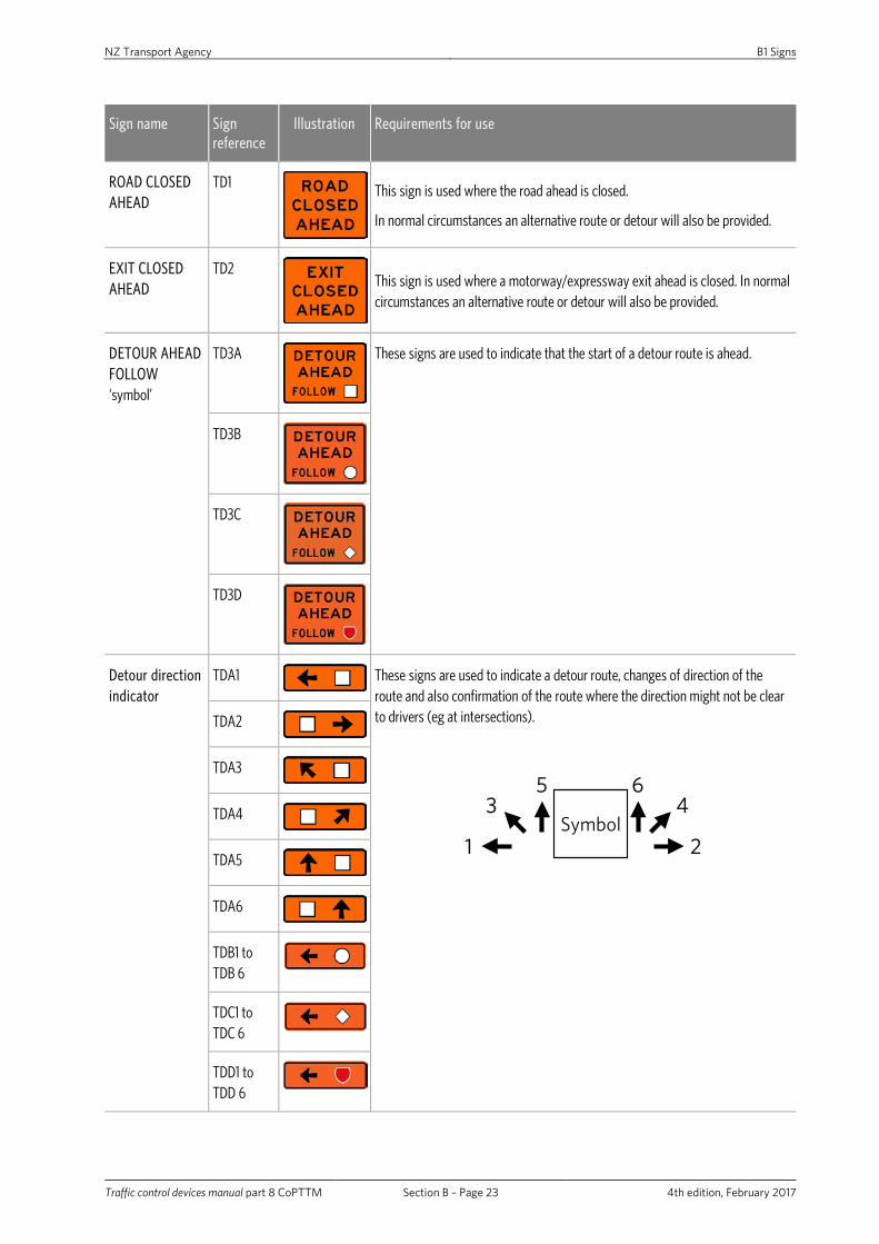
ROAD CLOSED AHEAD
TD1
This sign is used where the road ahead is closed.
In normal circumstances an alternative route or detour will also be provided.
EXIT CLOSED AHEAD
TD2
This sign is used where a motorway/expressway exit ahead is closed. In normal circumstances an alternative route or detour will also be provided.
DETOUR AHEAD FOLLOW ‘symbol’
TD3A
These signs are used to indicate that the start of a detour route is ahead.
TD3B
TD3C
TD3D
Detour direction indicator
TDA1
These signs are used to indicate a detour route, changes of direction of the route and also confirmation of the route where the direction might not be clear to drivers (eg at intersections).
Symbol1 2
3 45 6
TDA2
TDA3
TDA4
TDA5
TDA6
TDB1 to TDB 6
TDC1 to TDC 6
TDD1 to TDD 6

NZ Transport Agency B1 Signs
Traffic control devices manual part 8 CoPTTM Section B – Page 24 4th edition, February 2017
Sign name Sign reference
Illustration Requirements for use
PILOT CAR FOLLOW ME
TV1
This sign is attached to the rear or roof of a pilot vehicle which is used to lead traffic through a worksite at a desired speed.
TV1 signs are used in conjunction with MTCs using RP4/RP41 STOP/GO paddles.
SITE ACCESS
‘_’ 00m
TZ1L
This sign is erected to give advance warning of an approved access point to a site located adjacent to the road, when the site access is directly off a live lane on that road.
TZ1R
SITE ACCESS
Direction indicator
TZ2L
This sign may be erected at the approved access to a site located adjacent to the road when the site access is directly off a live traffic lane on that road.
TZ2R
CROSSING CLOSED PLEASE USE ALTERNATIVE CROSSING
TU1
This sign is used where a formal pedestrian crossing place is no longer available because of road works or some other temporary activity.
TU3 type pedestrian direction signs must be used to direct pedestrians to another formal crossing point.
FOOTPATH CLOSED PLEASE USE OTHER SIDE
TU2
This sign is used where a formal footpath cannot be used because of road works or some other temporary activity and there is an alternative footpath on the other side of the road.
TU2 signs must not be used on roads with a speed limit greater than 65km/h or on level 2 and 3 roads.

NZ Transport Agency B1 Signs
Traffic control devices manual part 8 CoPTTM Section B – Page 25 4th edition, February 2017
Sign name Sign reference
Illustration Requirements for use
Pedestrian direction
TU31
These signs are used to guide pedestrians to a temporary route or formal crossing point, and indicate the alignment of the temporary route, when the normal facility is not useable due to road works or some other temporary activity. TU32
TU33
TU34
TU35
TU36
Cyclist direction TU41
These signs are used to guide cyclists to a temporary route or formal crossing point, and indicate the alignment of the temporary route, when the normal facility is not useable due to road works or some other temporary activity.
TU42
TU43
TU44
TU45
TU46

NZ Transport Agency B1 Signs
Traffic control devices manual part 8 CoPTTM Section B – Page 26 4th edition, February 2017
Sign name Sign reference
Illustration Requirements for use
STOP / GO paddle
RP4
These signs may only be used by personnel that have been trained as MTCs by the STMS. Refer to subsection C10.2 Stop/go operations (manual traffic control).
The RP4 may be combined with either the RP41 Go or the RP42 SLOW paddle.
MTCs using these paddles must have the following signs in advance:
• T1A/B ROAD WORKS
• TA2 manual traffic control, and
• TG1 speed limit – TEMPORARY signs (30km/h or less).
RP41
RP42
PASS WITH CARE
TV4 and RD6L
This sign advises road users to take care whilst passing.
It is mounted on the rear of shadow and work vehicles involved in temporary mobile operations.
The RD6L or RD6R sign may be omitted when the vehicle is fitted with an arrow board.
Where a vehicle in a mobile operation is constantly changing position in the lane and it is impractical to frequently change the RD6L/R sign, this component may be omitted.
TV4 and RD6R
TV4
Bridge end markers
This sign is used to mark the narrowest part on the left side of bridges and similar end hazards such as barriers or barrier terminals.
This sign is used to mark the narrowest part on the right side of bridges and similar end hazards such as barriers or barrier terminals.
Hazard marker
Used to mark service poles and other isolated hazards such as flared barrier terminals.

NZ Transport Agency B1 Signs
Traffic control devices manual part 8 CoPTTM Section B – Page 27 4th edition, February 2017
B1.4.3 End of works
Sign name Sign reference
Illustration Requirements for use
Speed limit
10, 20, 30, 40, 50, 60, 70, 80 and 90km/h
RS1
These signs are used to de-restrict the speed of traffic after passing through a temporary speed limit.
On all roads, except level LV roads, the RS1 signs must be gated (ie a sign on both sides of the road).
The sign must be placed opposite the TG1/RS1 sign on two-way two-lane roads.
On one-way carriageways a TG2 WORKS END sign is attached as a supplementary plate and placed at the appropriate sign spacing distance past the working space or other hazard area.
Speed limit 100km/h
RS2
Speed limit De-restriction
RS3
WORKS END TG2
This sign is used to indicate the end of a worksite that has T1 type advance warning signs.
THANK YOU TG31
This sign is used to indicate the end of another hazard area indicated with T2 type advance warning signs and also worksites indicated with TR1, TR2, TR3 and TF type advance warning signs.
WORKS END THANK YOU
TG2/ TG31
This sign combination may be used to indicate the end of any worksite or other hazard area when the RCA or person with delegated authority, considers the combined message is desirable.
DRY YOUR BRAKES
TG4
This sign is used to indicate the end of a section of road that has been signed with T2A/B and T211 FLOODING advance warning signs.
DETOUR ENDS TD5
This sign is used to indicate the end of a temporary detour route.
CEMENT SPLASHES WASH CAR TODAY
TG51
These signs are used to augment other signs at worksites where lime or cement stabilisation is being undertaken and vehicles travelling through the worksite can become contaminated with lime or cement splashes. The signs are not usually be required under dry working conditions.
LIME SPLASHES WASH CAR TODAY
TG52

NZ Transport Agency B2 Delineation devices
Traffic control devices manual part 8 CoPTTM Section B – Page 28 4th edition, February 2017
B2 Delineation devices
B2.1 General
Delineation devices such as cones, tubular delineators and barrels, must be specifically designed and manufactured for temporary traffic management (TTM) use.
Manufacturers must be able to demonstrate colour and luminance compliance and photometric performance compliance of the retro-reflective material from a recognised independent testing laboratory's certificate of compliance. Such certificate must note the device tested.
In order to confirm device compliance with CoPTTM section B2 Delineation devices, the letters TTMC XX/YY (month and year of compliance certificate) of a practicable size must be embossed or otherwise permanently marked on the upper base of the device.
This revised compliance requirement will come into effect upon publication.
B2.1.1 Manufacture and supply
To enable manufacturers and suppliers time to make the changes required, such devices made to the previous specification will remain compliant until 1st January 2016. After this date all items manufactured and sold must be compliant to the revised specifications included in this edition.
B2.1.2 Use
Devices compliant to the previous edition of CoPTTM purchased prior to this date may remain in use until such time as they are no longer suitable for purpose.

NZ Transport Agency B2 Delineation devices
Traffic control devices manual part 8 CoPTTM Section B – Page 29 4th edition, February 2017
B2.2 Colour
All delineation devices (eg cones, tubular delineators and barrels) must be fluorescent orange with:
a. chromaticity coordinates in accordance with table 2.5 of AS/NZS 1906.1:2007,
b. minimum luminance factor in accordance with table 2.8 of AS/NZS 1906.1:2007.
In addition, the internal colour and the underside of the base of cones, tubular delineators and barrels must be either white or orange to ensure the device remains visible if knocked over. Orange must be compliant to a. above but need not be fluorescent per b. above.
Note: Colour dispensation will be allowed for the underside of a cone base that is manufactured using a minimum of 30% of recycled cone material. In such instances colour must comply with the specification in AS/NZS 1906.4 for orange red:
x 0.690 0.595 0.458 0.550
y 0.310 0.315 0.404 0.450
For continued production to remain compliant and in order to avoid the need to test each batch for colour and luminance compliance, a certificate of compliance for the device may remain valid for a maximum of 36 months. During this time manufacturers are expected to take all practicable steps to ensure that colour and luminance remain within specification. A new certificate of compliance must be completed within 36 months.
Note: The NZTA reserves the right to effect or require confirmation testing at any time to reconfirm colour compliance.
B2.3 Retro-reflectivity
Delineation devices must have white or silver retro-reflective bands that:
• Meet a minimum of the photometric performance requirements for Class 1 material in table 2.2 of AS/NZS 1906.1:2007,
• Conform to the band width and positioning on the device as noted below, and
• Be affixed securely to the device with an adhesive that is appropriate for use with such material.
The certificate of compliance for retro-reflective material must be no older than 36 months.

NZ Transport Agency B2 Delineation devices
Traffic control devices manual part 8 CoPTTM Section B – Page 30 4th edition, February 2017
B2.4 Dimensions
On all levels of roads the cones, tubular delineators and barrels used for delineation purposes must have a minimum height of 900mm and an unballasted weight not exceeding 7kg.
A 450mm high cone may be used to delineate and protect wet road markings but will not be compliant for any other use.
Size (mm)
Use Number of bands
Band width (mm)
Height of bottom edge of bands from ground (mm)
900 All roads 2 At least 150
No wider than 165
650±5 Upper band
At least 100
No wider than 110
400±5 Lower band
450 To protect freshly painted road markings
1 100 250±5
Company logos applied to the sides of delineation devices must be no greater than 5000mm2 (eg 50mm x 100mm) with the top of the logo being no higher than 200mm (±20mm) from the road surface.

NZ Transport Agency B2 Delineation devices
Traffic control devices manual part 8 CoPTTM Section B – Page 31 4th edition, February 2017
B2.4.1 Cones All cones must:
• be sufficiently stable to remain upright in most anticipated service conditions
• have a base designed to stop the cone from rolling if knocked over • be capable of returning to their original shape after impact • be made of a flexible polymer or similar material Note: Delineators must not be installed in stacks of 2 or more. Refer to subsection C5.2.1 Use for more information on the reasons why delineators are not installed in stacks.
In locations where high-wind speed is a concern, cones may be either:
• ballasted with sandbags, as per B1.3.4 Sign stands and supports, or • stabilised using light weight short flexible connecting strips. The
combined weight of a single cone and the stabilising strip must not exceed 7.0kgs in weight.
B2.4.1.1 Cone bars
Light weight, striped, orange and black or yellow and black plastic poles with rings appropriate for purpose at each end. Rings are to fit onto the cone and thereby connect cones together. Cone bars may be used to provide a channel for pedestrians on worksites where workers are in attendance.
These must not be used to replace a safety fence and may not be left unattended when a worksite closes.
Cone bars must meet the following specifications:
Materials Rigid plastic
Weight Under 7kg.
Length Minimum length 1m - Extends up to 2.2m.
Diameter Minimum 35mm to 100mm.
Frangibility Non-splintering frangible type material.
Will not present a hazard to vehicles after falling from the cone support.
Colour/retro-reflectivity Alternating black and orange or black, and yellow stripes. Minimum length 150mm. Maximum length 300mm.
Orange or yellow must be Class 2 Engineer Grade retro-reflective sheeting complying with AS/NZS 1906.1:2007 Table 2.4
Refer to subsection C.5.2.4 Cone bars for information on how these cone bars may be used.

NZ Transport Agency B2 Delineation devices
Traffic control devices manual part 8 CoPTTM Section B – Page 32 4th edition, February 2017
B2.4.2 Barrels All barrels must have:
• a minimum base dimension of 600mm x 600mm • rectangular or slightly chamfered corners • a stable base design that will accommodate sandbags as ballast • be made of a flexible polymer or similar material • have the standard pattern of retro-reflective tape
B2.4.3 Tubular delineators
Tubular delineators may be either circular, or a “T” type profile with a fixed or weighted base. They must:
• if circular, be no less than 75mm when viewed from any direction • if a “T” type profile, the primary approach face must be no less than
75mm in width and the reinforcing spine measurement no less than 55mm from primary face
• have the standard pattern of retro-reflective tape • be capable of returning to their original shape after impact (unless
dislodged from its base) • must not use a method of fixing that will damage the pavement
surfacing.
Note: In some specific circumstances NZTA may approve use of a flat delineator profile when it forms part of a system that includes a continuous centreline base.
B2.5 Device durability
It should be recognised by suppliers and users of these delineation devices that colour and luminance fades in direct sunlight.
While this cannot be avoided when the device is in use it may be good practice to store out of direct sunlight when not in use.
Users should be aware of device suitability for purpose at the time of use; that colour and retro-reflective performance is appropriate for the conditions, retro-reflective bands remain firmly affixed in position and the device is clean of environmental soiling. Refer also to subsections C19.3.4 and C19.3.5.

NZ Transport Agency B3 High visibility garments
Traffic control devices manual part 8 CoPTTM Section B – Page 33 4th edition, February 2017
B3 High visibility garments
B3.1 Material compliance
All material used in the manufacture of the garment must comply with the joint Australian and New Zealand Standard AS/NZS 1906.4:2010 Retro-reflective materials and devices for road traffic control purposes Part 4: High Visibility Materials for Safety Garments.
Manufacturers must be able to demonstrate compliance of high visibility background and retro-reflective materials used in the manufacture of all compliant garments to AS/NZS 1906.4:2010 from a recognised independent testing laboratory's certification of compliance.
Note: Clause 1.5 previously included in the AS/NZS 1906.4:1997 Standard has been deleted in the AS/NZS 1906.4:2010 Revision. This eliminates automatic cross compliance from EN 471 Standards. Materials used in the manufacture of all garments must now be tested and approved to the AS/NZS 1906.4:2010.
B3.1.1 Colour
The background material must be fluorescent Class F orange red conforming to the requirements of clause 2.3, Table 2.1 and Table 2.2 in AS/NZ1906.4:2010 when tested in a dry condition. The measurement for fluorescence is made over a black background therefore some open mesh materials may not comply.
Where requirements such as the risk of static electricity build-up for gas related projects, or the need for fire retardance exist, contractors may wear garments made from a fibre incapable of retaining a fluorescent colour, Class NF high visibility non-fluorescent coloured material conforming to clause 2.4, Table 2.1 and Table 2.3 in AS/NZS 1906.4:2010, when tested in a dry condition may be used.
All Class F and Class NF background materials must comply with the wet weather performance test specified in clause 2.6 of AS/NZS1906.4:2010 meeting all the requirements of clause 2.3 (Class F) and clause 2.4 (Class NF) except for a reduction in luminance factor to not less than 85% of that specified in Table 2.2 for Class F materials and Table 2.3 for Class NF materials.
Although the wet weather performance test is noted as optional for Class F material compliance with the AS/NZ1906.4:2010 Standard, all Class F and Class NF background material must comply with this test as noted for compliance with section B3 High visibility garments.
B3.1.2 Retro-reflectivity
The retro-reflective material must comply with the specification for Class ‘R’ material as noted in Section 3 and Table 3.2 of AS/NZS1906.4:2010.
Retroreflective orange red material for STMS panels must comply with the colour specification for Class F background material as noted in Clause B3.1.1 and exhibit a level of retro-reflectivity no less than 60 CIL/m2 at entrance angle 5.0 degrees and observation angle 0.2 degrees.
Note: Rainfall performance and luminance factor tests are not required for the retroreflective panels.

NZ Transport Agency B3 High visibility garments
Traffic control devices manual part 8 CoPTTM Section B – Page 34 4th edition, February 2017
B3.2 Logos
Garments must not display any lettering, symbols or logos on any compliant high visibility material except within an area located on the upper front left side of the garment.
The maximum area permitted is 7500mm2 (eg 100mm x 75mm).
Garment designs that include a clear plastic pocket where a business card or similar identification may be displayed must locate this pocket within the above described maximum 7500mm2.
Where required for related safety reasons a fabrics technical recognition I.D. may be added in an area not exceeding 30mm x 30mm (900mm2) to the upper front right side of a garment.
A manufacturers label to a maximum size of 50mm x 20mm may be sewn or printed on non-compliant material on the lower sleeve or leg.
Note: The STMS garment is limited to the STMS logo located on the upper front left side of the garment and as specified on the back of the garment and the technical recognition I.D. as appropriate. Other logos or labels may not be added.
B3.3 Garment compliance
Garment compliance is based on the Australian and New Zealand Standard AS/NZS 4602.1:2011 High visibility safety garments Part 1: Garments for high risk applications and the additional subsections that follow herein. Because all background high visibility material must comply with the wet test, as specified in subsection B3.1.1 Colour, new compliance letters ‘TTMC-W’ of a practicable size must be included on the garment label to confirm that the garment meets the requirements and is compliant with section B3. Note: Refer also to subsection B3.4.7 Exemption for extra small size garments.
All retro-reflective material applied to garments, including extra small size garments complying with subsection B3.4 Garment design must be in strips no less than 50mm wide. Hoops must completely encircle the torso with no breaks except for the permitted front opening. Braces or the rear cross configuration must meet at the top of the shoulder and at the hoops.
Garment compliance must be achieved for a recognised small garment designed for a size 92-95cm body chest measurement. This design must remain consistent throughout the garment size range, grading increasing or decreasing proportionately with the design integrity of the compliant small size.
Garment designs must not be altered without the direct authority of the NZTA. The NZTA may request a garment manufacturer to present a compliance certificate to confirm garment design compliance. In such instances the garment manufacturer will be required to forward material compliance certificates covering colour, luminance and retro-reflectivity with the garment to an NZTA approved industrial testing laboratory.

NZ Transport Agency B3 High visibility garments
Traffic control devices manual part 8 CoPTTM Section B – Page 35 4th edition, February 2017
B3.4 Garment design
The Australian and New Zealand standard AS/NZS 4602.1:2011 has now been amended by Amendment 1:2016. This amendment has created a variation between CoPTTM and AS/NZS 4602.1. Only one measurement is involved and the implications of this amendment remain under discussion. We are hopeful of having a resolution by 1 May 2017. A CoPTTM Technical Note will be published in the CoPTTM section of the NZ Transport Agency website.
B3.4.1 Sleeveless vest
B3.4.1.1 Sleeveless vest requirements
The sleeveless vest design, based on the Australian and New Zealand standard AS/NZS 4602.1:2011 must include the following additional requirements:
• when calculating the area of high visibility background material as specified in clause 6.4.2 in AS/NZS 4602.1:2011 the measurement rectangle shown in clause 6.4.5 and Appendix A may be extended below waist level to the bottom of the garment providing such extension for the small size does not exceed 680±5mm at the front
• the design must include a shirt tail back that is 150±5mm longer than the front
• the garment’s shirt tail may be split, providing an overlap of material ensures that continuity of background material is maintained. It is recommended that a hook and loop product secures the split. This feature may be included if there is a danger that the garment could snag when the wearer alights from any construction equipment. However, good practice dictates that when alighting from any construction equipment the operator faces the vehicle
• background high visibility material must encircle the torso from the top without the inclusion of any other colour except for:
i. Specified retro-reflective material ii. Permitted front opening and
iii. Permitted logo and technical ID area • the minimum qualifying area measurement of background high visibility
material for the recognised small size vest not covered by retro-reflective material or printing must be:
i. Front of garment 0.21m2
ii. Rear of garment including the 150mm shirt tail 0.27m2 • a permitted front opening to accommodate a zip fastener or similar
closing device may be no wider than 25mm. Zip colour may be black but a colour matching the garment colour is preferred. Any buttons, domes or similar closure devices on any compliant high visibility must match the colour of the garment (matching colour need not be compliant)
• compliant retro-reflective material must be positioned to comply with the pattern in Figure 1

NZ Transport Agency B3 High visibility garments
Traffic control devices manual part 8 CoPTTM Section B – Page 36 4th edition, February 2017
• the retro-reflective elements must form a recognised belt and braces pattern with an additional horizontal strip on the shirt tail located 50±5mm above the bottom hem. The braces join the belt at the front, passing over the shoulder to the belt at the back
• each brace must be spaced a minimum of 150mm apart at the belt, front and back as shown in Figure 1
• An optional cross configuration permitted for the back only must meet the front braces at the shoulder and the belt at the back vertically below the shoulder position to comply with the pattern in Figure 1
• The optional retroreflective cross configuration on the back of a garment is not permitted for STMS garments.
Note: Refer to subsection B3.4.7 Exemption for extra small size garments that follows.
High visibility garments must always be worn correctly fastened.
150±5mm
Retr
o-re
flect
ive
strip
53
0 ±
20m
m
Ove
rall
Len
gth
at fr
ont n
ot
to e
xcee
d 6
80 ±
5mm
Min150mmMax 25mm
50±5mm
Top and bottom of cross must align vertically
Figure 1: Sleeveless vest (size small).

NZ Transport Agency B3 High visibility garments
Traffic control devices manual part 8 CoPTTM Section B – Page 37 4th edition, February 2017
B3.4.1.2 Application of cross configuration on back of high visibility garment
To date NZTA has seen little evidence that supports any improvements in safety by using the cross configuration on the back of high visibility garments rather than the belt and braces configuration.
Despite this lack of evidence NZTA is allowing the use of an optional cross configuration on the back of high visibility garments.
The optional retroreflective cross configuration on the back of a garment is not permitted for STMS garments.
Contractors will be able to use this optional cross configuration for their staff but will not be able to require subcontractors or any visitors to site to have the cross configuration rather than the belt and braces configuration on the back of their high visibility garments.
The effective date for the introduction of the cross configuration will be 1 October 2016.
B3.4.2 STMS and MTC garments
Two special purpose garments differ from the standard compliant orange coloured high visibility garment range specified in section B3.4 Garment design.
Although these garment designs must comply with the standard compliant orange garment design the background material colour must become a compliant fluorescent yellow where specified.
Both garments identify the specialised responsibility of the wearer.
B3.4.2.1 STMS sleeveless vest
The STMS sleeveless vest enables the person responsible for TTM at a worksite to be readily identified.
The STMS vest (Figure 2A) has the same specifications as the sleeveless vest specified in subsection B3.4.1 Sleeveless vest except for the following subsections:
• the background material colour must be fluorescent yellow, commonly known as lime yellow, as specified in clause 2.3, Table 2.1 and Table 2.2 of AS/NZS 1906.4:2010. Note: Class NF non fluorescent yellow high visibility background material may be used for an STMS vest when appropriate. (Refer to subsection B3.1.1 Colour)
• a retro-reflective fluorescent orange red panel measuring 150mm x 150mm (±10mm) must be placed on the upper left front of the garment. This panel may cover some of the retro-reflective element at the front and replaces the permitted logo area. Refer to subsection B3.2 Logos
• a retro-reflective fluorescent orange red panel measuring 300mm x 150mm (±10mm) must be placed on the upper back of the garment, between the retro-reflective braces. This panel may cover some of the retro-reflective elements at the back.

NZ Transport Agency B3 High visibility garments
Traffic control devices manual part 8 CoPTTM Section B – Page 38 4th edition, February 2017
50±5mm
Min150mm
Ove
rall
Leng
th a
t fro
nt n
ot
to e
xcee
d 6
80 ±
5mm
150±5mm
Retr
o-re
flect
ive
strip
53
0 ±
20m
m
150mm
300mm150mm
Max 25mm
150mm
Figure 2A: STMS sleeveless vest (size small).
The legend, STMS, must be displayed on the back and front left orange red panels in the following manner:
The optional retroreflective cross configuration on the back of a garment is not permitted for STMS garments.
The STMS sleeveless vest may be substituted by a long sleeved coat, overalls or miscellaneous garment design but must maintain the STMS badging and colour specification.
An STMS on all Level 2 and Level 3 roads must wear this garment.
This garment must also be worn by an STMS on Level LV and Level 1 roads where there are three or more personnel on the site. Where there are less than three personnel on the site the STMS may wear a standard orange red garment.
Colour Black
Font Helvetica Bold
Letter height Front 50±2mm
Back 100±2mm

NZ Transport Agency B3 High visibility garments
Traffic control devices manual part 8 CoPTTM Section B – Page 39 4th edition, February 2017
B3.4.2.2 Optional MTC Garment Sleeve
The optional addition of fluorescent yellow material for the sleeve of the MTC STOP/GO operator is designed to provide additional visibility for this function when thought appropriate for the location.
The only item of difference to the standard compliant orange garment is the sleeve colour and the addition of retroreflective hoops around the arms to enhance this function when required at night. No additional changes may be included.
The sleeve colour must comply with the colour specified for the STMS Sleeveless vest (refer subsection B3.4.2.1 STMS sleeveless vest). Two compliant retro-reflective hoops must be positioned to comply with the pattern in Figure 2B. Each sleeve must have two retroreflective hoops, one positioned above the elbow and one below the elbow and close to the wrist.
Figure 2B: Optional MTC sleeve for Stop/Go operator
B3.4.3 Long-sleeve coat
A worker, supervisor or visitor may, in some instances, find it necessary or practicable to wear a long-sleeve outer coat. If this garment is to act as a high visibility garment it must comply with the general requirements for the high visibility sleeveless vest specified in subsection B3.4.1 Sleeveless vest as well as the following additional subsections:
• the 150mm shirt tail design is to be deleted • the minimum qualifying area measurement of background high visibility
material for the recognised small size coat not covered by retro-reflective material or printing must be measured in the same way as the sleeveless vest specified in subsection B3.4.1 Sleeveless vest except that the measurement rectangle must extend a minimum of 830mm at the front and back. Sleeves are not included in this area
• the area of background material must be determined as follows: i. Front of garment 0.3m2
ii. Rear of garment 0.3m2 • the sleeves of the garment must be the same fluorescent colour as the
torso to a point between the elbow and the wrist • compliant retro-reflective material must be positioned to comply with
the pattern in Figure 3

NZ Transport Agency B3 High visibility garments
Traffic control devices manual part 8 CoPTTM Section B – Page 40 4th edition, February 2017
• An optional cross configuration permitted for the back only must meet the front braces at the shoulder and the belt at the back vertically below the shoulder position to comply with the pattern in Figure 3
• a hoop of complying retro-reflective material must be located between the wrist and the elbow on each sleeve. This may be at the point of a colour change if the lower arm design includes a different colour. Note: An optional hoop of compliant retro-reflective material may be located on the sleeves above the elbow
• a strip of complying retro-reflective material must be located on the back of the garment from side seam to side seam positioned 50±5mm from the bottom hem. Note: An option permits this strip to completely encircle the garment.
Figure 3: Long sleeve coat (size small).
• Non-compliant colours may not be located within the qualifying torso area as trim or pocket flaps. Collar material may be a non-compliant colour but any such material that covers qualifying high visibility material in its normal worn position must be deducted from the qualifying torso area
• to lessen the effect of wear discolouration, non qualifying material colours may be used:
i. As noted above for the garment collar
ii. Below the retro-reflective hoop at the midpoint between elbow and wrist.

NZ Transport Agency B3 High visibility garments
Traffic control devices manual part 8 CoPTTM Section B – Page 41 4th edition, February 2017
B3.4.4 Overall garment
Where required, a worker may find it necessary or practicable to wear a one piece overall type garment. If this garment is to act as a high visibility garment it must comply with the general requirements for the high visibility sleeveless vest specified in subsection B3.4.1 Sleeveless vest as well as the following additional subsections:
• the 150mm shirt tail design is to be deleted • the minimum qualifying area measurement of background high visibility
material for the recognised small size garment not covered by retro-reflective material or printing must be measured in the same way as the sleeveless vest specified in subsection B3.4.1 Sleeveless vest except that the measurement rectangle must be extended to a point on the leg above the knee. Sleeves are not included in this area
Minimum retro-reflective length 380 mm
High
vis
ibili
ty to
a p
oint
ab
ove
the
knee
High
vis
ibili
ty to
a p
oint
ab
ove
the
knee
Figure 4: Overall garment (size small).

NZ Transport Agency B3 High visibility garments
Traffic control devices manual part 8 CoPTTM Section B – Page 42 4th edition, February 2017
• the minimum area of background material must be determined as follows:
i. Front of garment 0.3m2 ii. Rear of garment 0.3m2
• the sleeves of the garment must be the same high visibility orange colour as the torso to a point no less than midway between the elbow and the wrist
• compliant retro-reflective material on the torso must be positioned to comply with the pattern in Figure 4
• An optional cross configuration permitted for the back only must meet the front braces at the shoulder and the belt at the back vertically below the shoulder position to comply with the pattern in Figure 4
• a hoop of complying retro-reflective material must be located between the wrist and the elbow on each sleeve and above the knee on each leg to enhance long distance recognition of the wearer as outlined in Appendix B of AS/NZS 4602.1:2011. These hoops of retro-reflective may be located at a change of colour if a change is designed. Note: An optional hoop of compliant retro-reflective material may be located on the sleeves above the elbow and on the legs below the knee
• non-compliant colours may not be located within the qualifying area as trim or pocket flaps. Collar material may be a non-compliant colour but any such material that covers qualifying high visibility material in its normal worn position must be deducted from the qualifying torso area
• to lessen the effect of wear discolouration non qualifying material colours may be used:
i. As noted above for the garment collar
ii. Below the retro-reflective hoop between elbow and wrist on the arm and below the upper hoop on the leg of the overall.
B3.4.5 Miscellaneous garments
Garment types alternative to the primary garment specified in subsection B3.4.1 Sleeveless vest such as Polo shirts, woven shirts, ‘T’ Shirts and polar fleece garments may be granted compliance providing the following is met:
• the minimum qualifying area measurement of background high visibility material for the recognised small size garment not covered by retro-reflective material or printing must be: I. Front of garment 0.21m2
II. Rear of garment including the 150mm shirt tail 0.27m2 Note: Sleeves are not included in this area

NZ Transport Agency B3 High visibility garments
Traffic control devices manual part 8 CoPTTM Section B – Page 43 4th edition, February 2017
Figure 5: Miscellaneous garment size small Long Sleeved Polo.
• the configuration of compliant retro-reflective material complies with the configuration specified in subsection B3.4.1 Sleeveless vest including a strip on the shirt tail at the back
• An optional cross configuration permitted for the back only must meet the front braces at the shoulder and the belt at the back vertically below the shoulder position to comply with the pattern in Figure 5
• where the design includes short sleeves they must remain the same high visibility colour as the garment. If long sleeves they must remain the same high visibility colour to a point no less than midway between the elbow and wrist
• if the garment has long sleeves, placement of a compliant retro-reflective hoop on the arm between the elbow and the wrist is required as is specified in subsections B3.4.3 Long-sleeve coat and B3.4.4 Overall garment and Figures 3 and 4.
i. Material area in the sleeves must not be used to achieve area compliance for high visibility background colour
ii. An optional hoop of compliant retro-reflective material may be located on the sleeves above the elbow

NZ Transport Agency B3 High visibility garments
Traffic control devices manual part 8 CoPTTM Section B – Page 44 4th edition, February 2017
• the area of compliant high visibility background material is measured from material that will be visible when the garment is worn in its normal manner. Note: Wearers should be aware that such garments will not comply when tucked into trouser type garments
• non-compliant colours may not be located within the qualifying torso area as trim or pocket flaps. Collar material may be a non-compliant colour but any such material that covers qualifying high visibility material in its normal worn position must be deducted from the qualifying torso area.
B3.4.6 Fire Service garments
The objective of this subsection is to recognise special requirements for firefighters while working on or near the road at a fire or other emergency where the wearing of safety garments must first meet the unique requirements of either AS/NZS 4967 Garments for structural firefighting or AS/NZS 4824 Garments for Wildland firefighting.
Whilst carrying out routine maintenance operations such as hydrant testing for a local council high visibility garments must be TTMC-W compliant.
Essential Fire Service related garment recognition patches or printing may exceed subsection B3.2 Logos specifications provided size and number are limited and do not risk overall visibility safety.
Background high visibility material may be yellow green Class F or Class NF conforming to the requirements of clause 2.3, Table 2.1 and Table 2.2 or Table 2.3 in AS/NZ1906.4:2010. Such material must comply in a dry and wet condition as noted in subsection B3.1.1 Colour.
Where practicable a high visibility vest complying with subsection B3.4.1 Sleeveless vest may be worn providing this is appropriate for the situation at hand and the wearing of such a garment does not become hazardous for the wearer.
Fire Service personnel attending such emergencies within the roading network are exempted from wearing TTMC-W compliant high visibility vests in the following circumstances:
• the fire service personnel are at the immediate fire or potential fire location
• high visibility is achieved by a garment that in addition to compliance with AS/NZS 4967 or AS/NZS 4824 Standards also complies with AS/NZS 4602.2 High visibility safety garments Part 2: Garments for fire service personnel
• high visibility is achieved by a garment that in addition to compliance with AS/NZS 4967 or AS/NZS 4824 Standards also complies with AS/NZS 4602.1 High visibility safety garments Part 1: Garments for high risk applications.
Fire service personnel carrying out traffic control support of an emergency are reminded of the need to be visible.

NZ Transport Agency B3 High visibility garments
Traffic control devices manual part 8 CoPTTM Section B – Page 45 4th edition, February 2017
B3.4.7 Exemption for extra small size garments
Dispensation for an extra small fitting garment will be permitted provided it meets the requirements of the compliant recognised small size garment with the following exceptions:
• if on an extra small sized garment designed to fit a chest size of less than 92cm where it is not possible to accommodate the minimum specified area of high visibility background material, the garment must be deemed to comply provided the garment design grading decreases proportionately without affecting the design integrity of the compliant small size of the garment range
• such extra small size garment must maintain the same configuration of compliant retro-reflective material as specified for the recognised small size of the design.
In addition, the following subsections also apply to extra small fitting garments:
• a card, which is clearly visible to a purchaser, must be included in the garment’s packaging stating that this extra small fitting garment has reduced visibility in both day and night conditions and that, because of this limitation, those wearing the garment would normally avoid working in areas of high risk
• an additional separate sewn in label clearly visible to the wearer (refer to Figure 6) must alert the wearer to the reduced visibility of extra small fitting garments.
Management must ensure that any employee wearing an extra small fitting garment is aware of the potential hazards resulting from its lower visibility.
Figure 6: Extra small garment label

NZ Transport Agency B3 High visibility garments
Traffic control devices manual part 8 CoPTTM Section B – Page 46 4th edition, February 2017
B3.5 Garment durability
Due care and maintenance of high visibility safety garments is recommended. Garment soiling, colour fading of background high visibility material, abrasion and damage to retro-reflective strips all affect the high visibility performance of safety garments.
Employers and wearers of high visibility safety garments must be aware of the condition of any such garment on the day it is being worn. Garments must be inspected on a regular basis and replaced if they are badly damaged, soiled or faded, or the retro-reflective material has ceased to function. Note: Refer also to subsection C19.3.6 Evaluation guide: High visibility garments.
To maximise durability of high visibility garments:
• high visibility garments be kept clean by washing or cleaning as regularly as is practicable ensuring that manufacturer’s instructions are noted and followed
• where ever practicable garments should be stored in such a way as to limit fading of high visibility background material especially fluorescent colours. When not in use place in a dark location away from natural light. High visibility background material colour, especially fluorescent colours, fade when left in natural daylight and especially in direct sunlight.
B3.6 Optional illuminated attachments
In specific circumstances within a worksite it may be appropriate to enhance personal night-time/low light retro-reflective garment conspicuity with the addition of a self illuminating system that will attach to an approved high visibility garment that already complies with one of the options specified in subsection B3.4 Garment design
Such circumstances would normally be limited to specific locations within a worksite where moving vehicles and or equipment do not have or may not be operating an appropriate head light system that is necessary to provide retro-reflective light back to the driver of such vehicles or equipment. In areas where headlights are active the retro-reflective performance provides worker conspicuity and this will typically overpower an illuminated attachment.
The wearer of any such approved system must be aware that its performance is limited and will only be visible to a vehicle or equipment operator when positioned within the driver’s line of sight. The wearer must be instructed to be vigilant whenever working or moving behind operating vehicles that may be reversing and equipment that may swing through an operational circle.
Equally the wearer of an approved illuminated attachment must be responsible for ensuring it is fully charged and suitable for use at the time it is being used and that site management or the STMS is aware of its use on site.

NZ Transport Agency B3 High visibility garments
Traffic control devices manual part 8 CoPTTM Section B – Page 47 4th edition, February 2017
Any such system must be approved by the NZ Transport Agency, Traffic and Safety, prior to being marketed for use in TTM sites within the roading network.
To be approved, a system must be adjudged suitable for purpose and comply with the following specifications:
• the illuminating system must be removable from the garment during daylight hours or when not in use
• no part of the system may cover any part of the garment’s compliant retro-reflective configuration
• the illuminated area must be in the vertical plane and limited to the length of the vertical retro-reflective strips without crossing the retro-reflective hoop at the waist
• the colour when illuminated must be white or a close blue/white proximity. No other bold colours are permitted
• the illumination must be non flashing. If a flashing capability is possible it must not be activated on any TTM worksite
• to ensure compatibility with the retro-reflective strips the illuminated area must be not less than 10mm or more than 15mm in width
• during the hours of daylight no part of the illuminating attachment may cover any portion of the compliant area of day time high visibility material
• if the illuminating component of the system requires a permanently fixed attachment this must be transparent and not impair the compliant daytime background high visibility compliant area of the garment. Garments are only to be fitted with the attachment system where there is a high probability of regular use of the system. The permanently attached component must be no more than 10mm wider than the illuminating component
• the system design should ensure that, when attached, potential for the system to catch on machinery or structures is limited and or in case of the system being caught that it will release and not endanger the wearer
• any system approved must comply with subsection B3.2 Logos • when tested the surface luminance must be no less than 15cd/m2 or
greater than 25cd/m2 measured at 90 degrees to the illuminated surface • the battery system must be specifically matched to the system’s
requirements, be robust, light weight and weather proof and held firmly into a compliant pocket of the garment
• the tested system must demonstrate that the battery has the ability to maintain a level of performance suitable for purpose for a minimum of eight hours and preferably include a warning indicator for low battery status
• any garment fitted with a permanent attachment component for an illumination system must include this in the garments care instructions on the label.
Should a visiting site safety engineer sight an illumination system currently in use to be exhibiting a performance deemed not suitable for the situation at hand such engineer may require the system to be withdrawn from use and retested to determine that performance qualifies to this specification.

NZ Transport Agency B4 Logos, names and trademarks
Traffic control devices manual part 8 CoPTTM Section B – Page 48 4th edition, February 2017
B4 Logos, names and trademarks
B4.1.1 General Logos, company names and other trademarks must not be displayed on the front of TTM signs. The logo, company name or trademarks of the sign’s owner may be displayed on the back of signs provided they do not detract from the legibility or reflectivity of the sign.
No more than one logo is to be displayed on traffic signs, other traffic management devices and high visibility garments.
The requirements for high visibility garments are presented in subsection B3.2 Logos.
Traffic management devices, other than signs, and high visibility garments may have a logo displayed.
Stickers, or the like, used for sign-manufacturing purposes must not be reflective and they must be placed on the back of the sign.
B4.1.2 Area requirements for signs
Any logo displayed on a traffic sign must not exceed:
• 3000mm2 (eg 30mm x 100mm) on signs less than 1m2 or on any other traffic management devices
• 10,000mm2 (eg 100mm x 100mm) on traffic signs larger than 1m2.
B4.1.3 Area requirements for delineators
Cones, tubular delineators and barrels used for delineation purposes may have a company identifying logo not exceeding an area of 5000mm2 (eg 50mm x 100mm).
The logo must not extend more than 200mm up the side of the delineator.
B4.1.4 Retro-reflectivity
Logos must not be retro-reflective.

NZ Transport Agency B5 Portable traffic signals
Traffic control devices manual part 8 CoPTTM Section B – Page 49 4th edition, February 2017
B5 Portable traffic signals
B5.1 Single-lane signalised alternating flow
B5.1.1 General Portable traffic signals must comply with the Australian Standard AS 4191–1994 Portable traffic signal systems (AS 4197-1994) and must only have two phases. Each phase permits a particular traffic movement and consists of a green period, a yellow period and an all-red period.
Portable signals are usually adequate for traffic control at worksites where their operation is supervised. Where they are required to operate outside working periods they must be regularly monitored to ensure they are continuing to function correctly. The frequency of monitoring is to be documented in the TMP.
The requirements for a portable traffic signal installation are normally less stringent than those for a normal signalised intersection. The minimum requirements for a portable traffic signal installation are:
• a power supply source • two signal posts each with a three-aspect signal display • a vehicle-actuated detection system, except where a fixed time or
manually-operated signal operation is shown to be adequate • a system to link each item of hardware • a control mechanism • an audio alarm system to alert worksite staff in the event of signal
malfunction.

NZ Transport Agency B5 Portable traffic signals
Traffic control devices manual part 8 CoPTTM Section B – Page 50 4th edition, February 2017
B5.1.2 Certification of portable traffic signals
Portable traffic signals must be certified as complying with AS 4191–1994.
Contractors are required to apply to the RCA to use portable traffic signals.
Application must be made with the TMP and the details of the system must be provided (manufacturer and model description/number).
RCAs must approve the use of all portable traffic signals before they are installed at a worksite.
A register of compliant systems is available on the NZTA’s website.
The representative of the RCA must ensure that the system is listed as compliant before signing off the TMP.
New systems can be tested to AS 4191–1994 standards at either a qualified independent Australian laboratory or at Opus Central Laboratories in New Zealand. The Technical Note – Specification and Application for Portable signals available on NZTA’s website, outlines the process to be followed.
New approvals will be added as they pass testing. Testing is to be undertaken at own expense. For details of testing or to have a portable signal system tested apply to:
Senior Traffic and Safety Engineer (CoPTTM) NZ Transport Agency Private Bag 6995 Wellington 6141.
B5.1.3 Power supply
The power supply may be either mains or battery but the source and lamp combination must be able to produce the signal lantern light output required by the Austroads Guide to Traffic Management Part 10: Traffic Control and Communications Devices.
B5.1.4 Signal displays
At most worksites a single signal post with a three-aspect lantern display is sufficient. The display is normally positioned to the left, and adjacent, to a limit line that is located at a point where normal two-way traffic operation is restored.
The location of the signal displays in relation to the limit lines and adjacent carriageways must conform to the requirements of the Austroads Guide to Traffic Management Part 10: Traffic Control and Communications Devices.
B5.1.5 Detection system
Vehicle detection may be by microwave or infra-red detectors, or by induction loops cut in the road surface. The system must be set up to minimise false detections due to adjacent worksite activity and vehicles on the road that are leaving the controlled area.

NZ Transport Agency B5 Portable traffic signals
Traffic control devices manual part 8 CoPTTM Section B – Page 51 4th edition, February 2017
B5.1.6 Linking The linking between the signal displays on each approach to the controlled area may be provided by a hardwired cable system or by radio transmission.
Coordinated time clock systems are not recommended because a temporary failure on one approach will result in the loss of coordination. This is unacceptable under alternating flow conditions.
Where cable linking is used, and the cable must cross the trafficked carriageway within the controlled area, the cable is laid in a saw cut at the crossing point. If saw cutting is not feasible, vehicles may be ramped over the cable using an appropriate ramping system. In general the crossing is best positioned at the midpoint of the controlled area to minimise the effects of vehicle acceleration, braking and deceleration at the crossing point.
Radio linking must use a suitable frequency and be set up in such a manner that it is unaffected by interruptions to the line of sight between the signal equipment at each end of the controlled area.
In special circumstances linking cables may be suspended from securely-anchored wires. The cables must be at least 1m above the maximum legal vehicle height. Six metres is normally an adequate minimum clearance.
B5.1.7 Controller The signal controller must provide a two-phase operation with each phase having the following features:
• a fixed minimum green period • a variable or fixed maximum green period • a variable or fixed gap timer • a fixed yellow time which must not be less than three seconds, and • a variable all-red time.
The preferred method of operation for a vehicle-actuated system is that, in the absence of a vehicle demand, it ’rests-in-green’ on the last approach serviced.
Some portable controllers can generate a dummy opposing demand after a preset time, eg three minutes, to ensure a non-detected vehicle is never trapped on either approach.
B5.1.8 Maintenance and emergencies
A maintenance contract to ensure immediate priority attention to a fault in an alternating flow traffic signal system must be arranged prior to the installation of the system.
A person experienced in the operation of traffic signals undertakes the design and installation of the control and detection equipment.
The contractor must have access to a back-up system that can take over from the traffic signal operation in the event of unusual congestion or failure of the control system. The signal displays must be removed or securely covered before such a back-up system is implemented.

NZ Transport Agency B5 Portable traffic signals
Traffic control devices manual part 8 CoPTTM Section B – Page 52 4th edition, February 2017
B5.2 Types of operation
The three modes of portable traffic signal operation are:
• vehicle actuated • fixed time • manual.
B5.2.1 Vehicle-actuated operation
Vehicle-actuated operation is the preferred operating mode and must be used wherever possible.
Vehicle-actuated operation allows the signals to automatically respond to vehicle demands. Phase lengths are adjusted automatically to suit the traffic flows and this ensures that traffic queues and delays are kept to a minimum.
For alternating flow under vehicle-actuated operation the signals must change automatically when either:
• there is a steady stream of vehicles and the maximum green timer has expired, or
• the gap between successive vehicles is greater than a predetermined interval and the minimum green timer has expired.
If the phase changes at the maximum green time, a new demand must be automatically generated for that phase. This ensures that any vehicles stopped by the signal change and undetected will be serviced, without the need for the system to detect the arrival of another vehicle on that approach.
B5.2.2 Fixed-time operation
Fixed-time operation is an automatic mode that cannot respond to varying vehicle demands. The traffic signal cycles are set according to predetermined timings and this is likely to result in vehicles being delayed for no apparent reason when the road is clear.
Fixed-time control must, therefore, only be used under the following conditions:
• a vehicle detector fails, and • no manual signal operator is available.
B5.2.3 Manual operation
Manually-operated portable traffic signals are useful:
• when a detector fails in a vehicle-actuated system, and/or • for the management of plant crossing the road at irregular intervals.
NZ Transport Agency B5 Portable traffic signals
Traffic control devices manual part 8 CoPTTM Section B – Page 53 4th edition, February 2017
B5.3 Timing of signal displays
B5.3.1 Fixed minimum green
A fixed minimum green period of six seconds is normally sufficient to ensure that the traffic flow can start up and that detection of successive vehicles will activate the gap timer in the appropriate manner, which will extend the green period, up to the maximum green time set if necessary.
B5.3.2 Gap This timer is activated by the detection system and times the gap between successive vehicles on the approach to the signal, when the signal is showing a green display. Its normal value is in the range two to six seconds but it is site specific and very much dependent on traffic speed.
Traffic flows when the signal is showing a green display must be observed at various times of the day. If the phase seems to regularly terminate before the maximum green time expires, and the distances between successive vehicles in the traffic flow are not excessive, the gap time may be increased, in one-half second increments.
Conversely, if the phase seems to regularly terminate at the maximum green time or the distances between successive vehicles in the traffic flow seem excessive, the gap time may be decreased. Minor adjustment to the gap time can have a major effect on the efficiency of a vehicle-actuated traffic signal operation.
B5.3.3 Maximum green
For a vehicle-actuated traffic signal operation, the maximum green timing starts as soon as the green signal is displayed if there is already a vehicle call for the other phase, or immediately a vehicle call for the other phase is received during the current phase, whichever is the sooner.
The green signal will continue to be shown provided there is constant stream of traffic and vehicle spacings are less than the gap time setting. The phase will terminate when the maximum green timer expires.
When a fixed-time traffic signal operation is employed, the green time for each phase will always be the maximum value set, irrespective of traffic demands. Maximum green time settings may, therefore, be changed for the peak hours, off peak times, weekends and nights, to avoid excessive delays. Changes may be made manually or by ‘time of day’ commands, depending on the type of signal controller being used. Fixed-time traffic signal operation is NOT recommended for TTM.
The following method may be used for setting maximum green times at short duration worksites where flows do not exceed 800 vehicles per hour (vph) and are roughly equal in each direction.

NZ Transport Agency B5 Portable traffic signals
Traffic control devices manual part 8 CoPTTM Section B – Page 54 4th edition, February 2017
B5.3.3.1 Procedure
Step 1 - Measure the worksite length and set the maximum green time to the value shown the table below.
Maximum green settings
Worksite length (metres)
Maximum green time setting (seconds)
30 – 74 35
75 – 134 40
135 – 194 45
195 – 300 50
Step 2 - Observe the traffic queues at various times of the day. If the last vehicle in queue regularly takes more than one green period to reach the limit line, increase that approaches maximum green time setting by five seconds.
Where the traffic flows exceed 800vph a more precise calculation will be required to determine the appropriate maximum green time setting. A person familiar with traffic signal analysis must be employed to carry out this work.
B5.3.4 Fixed yellow The fixed yellow time for alternating flow traffic signal worksites is four seconds.
B5.3.5 All-red The length of the all-red period is a function of the length of the worksite, site conditions and the average speed of vehicles through the worksite. A very long all-red setting can result in long delays that cause road user frustration, which in turn can lead to a red signal being disregarded. A very short all-red signal, particularly where visibility is restricted, can be equally dangerous.
The all-red time must be at least five seconds. The all-red times recommended for straight level worksites are given in the table on the next page.

NZ Transport Agency B5 Portable traffic signals
Traffic control devices manual part 8 CoPTTM Section B – Page 55 4th edition, February 2017
Straight level worksite length (metres)
Recommended all-red time (seconds)
Less than 50 5
50 – 99 10
100 – 149 15
150 – 199 20
200 – 249 25
250 – 300 30
Note: Worksite length is the distance between the traffic signal limit lines at each end of the worksite.
The all-red time may need to be adjusted where gradient, road surface condition or a high proportion of heavy vehicles affect travel times through the worksite. As activity progresses the all-red times are reviewed on a regular basis to ensure they are neither too long nor too short.
B5.3.6 Inter-green The inter-green time is the period between successive green phases when all signals display a red aspect. The inter-green time is the sum of the yellow time and the red time for that phase, and allows vehicles to safely clear the controlled area.
B5.3.7 Start-up sequence
Portable traffic signals must start up with the following sequence: • display a flashing yellow signal on all approaches for at least 10 seconds • display a continuous yellow signal to all approaches for the preset yellow
time • display a red signal on all approaches for at least 10 seconds, and then • display a green signal for the first approach in the phasing sequence.
Portable traffic signals that comply with the AS 4191–1994 will automatically start up with this sequence.

NZ Transport Agency B5 Portable traffic signals
Traffic control devices manual part 8 CoPTTM Section B – Page 56 4th edition, February 2017
B5.3.8 Flashing yellow mode
In flashing yellow mode, the red and green signals remain blank and the yellow aspects on all approaches flash at a rate of approximately 60 flashes per minute.
Portable traffic signals must operate in a flashing yellow mode: • during the start-up sequence, and • automatically within a half a second of any of the following hazardous
conditions occurring: – a green signal is shown simultaneously on both approaches of an
alternating flow operation – a green or yellow signal is shown to one approach and red on the
other approach of a haul route crossing control operation – if one approach shows a green signal and the other approach shows
yellow signal – when any lamp fails – under fixed-time or vehicle-actuated operation a lamp fails to
extinguish – under manual operation a green or yellow signal does not remain
illuminated for the minimum green or yellow time – if more than one aspect is illuminated on a signal display – if the communication link between components in a system is
disrupted for a continuous period of five seconds. This applies to any breakdown in data transmission
– if a radio-linked system receives conflicting commands or status data from another signal installation within radio range.
The Traffic Regulations 1976 and The Official New Zealand Road Code include driving rules for the flashing yellow traffic signal display. When a traffic signal shows a flashing yellow display the give way rules apply.
Note: Flashing yellow will be displayed for a short period of time when traffic signals are starting up.
Portable traffic signals that comply with AS 4191–1994 must automatically display flashing yellows in accordance with this procedure.

NZ Transport Agency B6 Safety fences
Traffic control devices manual part 8 CoPTTM Section B – Page 57 4th edition, February 2017
B6 Safety fences
B6.1.1 General Safety fences are required to prevent people from gaining access into a hazardous area. This is particularly important at unattended worksites.
B6.1.2 Design B6.1.2.1 Safety fence requirements
Safety fences must:
• have a secure supportive top and bottom rail • have the top rail located a minimum of 1m above ground level • have the bottom rail located a maximum of 100mm above ground level • be continuous around the hazard • be clipped or joined together, if in sections, to form a continuous fence
surrounding the hazard • have top and bottom rails that terminate with a vertical post • have a child proof in-fill or solid panels that are difficult to climb and are
fluorescent orange or alternating white, and fluorescent orange in colour • remain upright and stable under all expected worksite conditions • be free of sharp objects.
B6.1.2.2 Child proof in-fill
Where vertical members are used they must be no greater than 100mm apart.
Where netting mesh is used, the diagonal gap in the mesh must be no greater than 75mm, which is achieved by a 50mm x 50mm mesh as shown.
Effective date for this change is 1 July 2016.

NZ Transport Agency B6 Safety fences
Traffic control devices manual part 8 CoPTTM Section B – Page 58 4th edition, February 2017
B6.1.3 Night use Amber-flashing warning lamps may be placed on safety fences and barricades refer to section C12.4.6. Amber flashing warning lamps.
On all levels of road where hazards parallel to the road are protected by safety fences, these fences must be fitted with suitable reflectorised delineators.
CoPTTM recommends the use of the 200mm x 150mm retro-reflective chevron delineators shown in subsection B12.1.4 Channelling traffic. These are to be installed at ten-metre spacings and at every change of direction of the safety fence or barricade.
B6.1.4 Plastic water-filled fences and barriers
Plastic water-filled fences and barriers that do not comply with the requirements of NZTA M23: Specification for road safety barrier systems must not be used as barriers.
However, plastic water-filled fences and barriers may be used as a safety fence under the following conditions:
• The design and installation must comply with the design requirements for safety fences listed above.
• Must be separated from any live lane by a minimum of a 1m lateral safety zone and a row of cones at the appropriate spacings.
• Must only be used in less than 65km/h speed environments.

NZ Transport Agency B7 Barricades
Traffic control devices manual part 8 CoPTTM Section B – Page 59 4th edition, February 2017
B7 Barricades
B7.1.1 General Barricades must only be used behind a line of delineation devices.
Barricades may be used to physically close roads.
Barricades must be lightweight, frangible and constructed from non-splintering plastic material. When in place on site the barricade, consisting of legs and a sight rail, must be joined together to form a one-piece unit.
Hurdles are not a recommended TTM device and CoPTTM discourages their use. Cones or barricades can usually be used instead of hurdles.
B7.1.2 Dimensions Barricades must:
• have sight boards with a vertical dimension of 150mm to 300mm and horizontal lengths of 600mm to 1800mm, and
• the sight board must be mounted with the centre line of the uppermost rail 900mm, ± 120mm tolerance, above the ground surface.
B7.1.3 Colour Barricades must be:
• a fluorescent orange colour that conforms to the chromaticity co-ordinates in table 2.5 AS/NZS 1906.1:2007, and
• conform to the minimum luminance factors specified with table 2.8 of AS/NZS 1906.1:2007.
Barricade sight boards must have alternating 100–150mm-wide white and fluorescent orange stripes that slope at 45 degrees to the vertical, with the lowest point of the stripes towards the live lane. The stripes must be at least class 1 retro-reflective material that conforms to table 2.2 AS/NZS 1906.1:2007 and must be applied to the full length of the sight board.

NZ Transport Agency B8 Horizontal arrow boards and light arrow system
Traffic control devices manual part 8 CoPTTM Section B – Page 60 4th edition, February 2017
B8 Horizontal arrow boards and light arrow system
B8.1 General
Arrow boards are used to:
• direct road users to the left or right, and • caution traffic.
Arrow boards are used extensively for mobile operations but they may also be used for static operations.
B8.1.1 Types of arrow boards
There are two types of arrow board:
• light arrow system (LAS), and • horizontal arrow board.
B8.1.2 When each are used
Level 2 and 3 roads:
• LAS or horizontal arrow boards must be used on all level 2 and 3 roads. • LAS must be used on level 2 and 3 state highways. • LAS or horizontal arrow boards must not be used to direct traffic into
opposing traffic flows.
Level LV and level 1 roads:
• Horizontal arrow boards may be used for both static and mobile operations on level LV and level 1 roads to increase levels of safety.
• Horizontal arrow boards must not be used to direct traffic into opposing traffic flows.
B8.2 Light arrow system (LAS)
B8.2.1 About the LAS
The LAS is used on level 2 and 3 state highways. The LAS is designed to operate as part of a gazetted sign R3-13.3 with:
• a red and white rear panel • a xenon warning light system • a 1500mm diameter RD6R or RD6L, and • in conjunction with an advanced warning variable message sign
(AWVMS).
The LAS design follows European best practice which has been proven to be more effective than the horizontal arrow board system.
It is recommended that all RCAs adopt this policy for level 2 and 3 roads.

NZ Transport Agency B8 Horizontal arrow boards and light arrow system
Traffic control devices manual part 8 CoPTTM Section B – Page 61 4th edition, February 2017
B8.2.2 Effective dates
It is recommended new vehicles be fitted with the LAS.
All new NZTA contracts awarded, for level 2 and 3 roads, from 1 July 2010 will require use of LAS.
Existing level 2 and 3 truck-mounted attenuator (TMA) rear panels must be retrofitted to comply by 1 July 2012.
B8.2.3 Specifications The details of the number and layout of lamps are shown in the following diagram.
The minimum number of lamps must be 24 with a maximum of 25.
The arrow lamps must comply with European Standard EN12352:2006 Traffic control equipment - Warning and safety light devices for Class L8H warning lights (EN12352:2006).
The following shows values for lights complying with EN12352:2006.
Class of warning light – L8H
Characteristic Requirements
Area of light emitting surface (cm2) >= 250
Diameter of light emitting surface (mm) >= 180
Angle range - horizontal +7.5° to -7.5°
Angle range - vertical +5.0° to -5.0°
Luminous intensity (cd) for nominal voltage:
• IRmin [minimum effective luminous intensity measured on the reference axis]
1500
• IAmax [maximum effective luminous intensity measured at any point within angle range]
5000
The arrow lamps are required to pulse at a rate of 55 to 75 flashes per minute, with the on-period twice the length of the off-period.
When the arrow lamps are operating, the two synchronised Xenon flashing lights must only flash during the off-period of the arrow lamps.
All lenses must be amber in colour.
Adjustment of the light intensity of the lanterns for night-time operations must be controlled by an automatic light-sensitive multistage light dimming device.
The light intensity during hours of darkness must not exceed 800 candelas since this may cause glare and make the sign difficult to read.
Note: The LAS system is gazetted as a sign.

NZ Transport Agency B8 Horizontal arrow boards and light arrow system
Traffic control devices manual part 8 CoPTTM Section B – Page 62 4th edition, February 2017
B8.3 Horizontal arrow boards
B8.3.1 General Horizontal arrow boards must be legible at distances greater than 800m.
They must at least comply with the requirements of the joint Australian and New Zealand standard AS/NZS 4192:2006 (and amendments) Illuminated flashing arrow signs (AS/NZS 4192:2006) and preferably with the American Federal Highway Administration’s Manual on uniform traffic control devices for streets and highways section 6F.61 Arrow boards and figure 6F-6 Advance warning arrow board display specifications.
B8.3.2 Design Horizontal arrow boards must have the following features:
Lamp colour Amber
Lamp diameter At least 80mm
Flash rate 25 to 40 flashes per minute
Number of lamps At least 25 and a minimum of 5 per chevron
Lamp dimming Adjustable intensity with automatic and manual switching to not more than 50 percent of rated voltage
Pilot lights, or other controls, located in the vehicle must be used to confirm the operation and mode of a horizontal arrow board.
B8.3.3 Size Horizontal arrow boards must be at least 1200mm wide by 600mm high.
B8.3.4 Rear panel A red and white rear panel, as specified below, will be required on all horizontal arrow boards with effective date of 1 July 2012:
• Primary strip – Red reflective class 1 retro-reflective. • Alternate strip – White reflective class 1 retro-reflective. These primary and alternate strips must be uniform in size and can be either 360mm or 140mm wide.
Note: The height and width measurements are minimums. Maximum measurements will be subject to legal vehicle widths and heights.
350
1600 Arrowboard
1200
600
1900
360
360
500
500
(All measurements are in millimetres)

NZ Transport Agency B8 Horizontal arrow boards and light arrow system
Traffic control devices manual part 8 CoPTTM Section B – Page 63 4th edition, February 2017
If the truck’s tray width does not allow for the full red hatching to be displayed on each side of the horizontal arrow board, this hatching width may be decreased to the width of the tray. The red hatching must be maintained in the panels above and below the arrow board.
The TV4 PASS WITH CARE sign must be displayed either above or below the red hatching. The RD6L/R signs are not to be used.
B8.3.5 Display configurations
The position on the carriageway of the vehicle carrying the horizontal arrow board determines which of the two horizontal arrow board displays approved for TTM use on New Zealand roads is to be shown.
Details of these display modes are given below:
Mode Display Situation
Single sequential A=arrow (with tail)
Arrow head moving left or right depending on the direction road users are being directed to follow.
The horizontal arrow board vehicle is in a live lane but a minimum lane width is available for traffic to safely pass on one side of the vehicle.
Phase Display
Phase 1
Phase 2
Phase 3 (after phase 3 the sequence returns to phase 1)
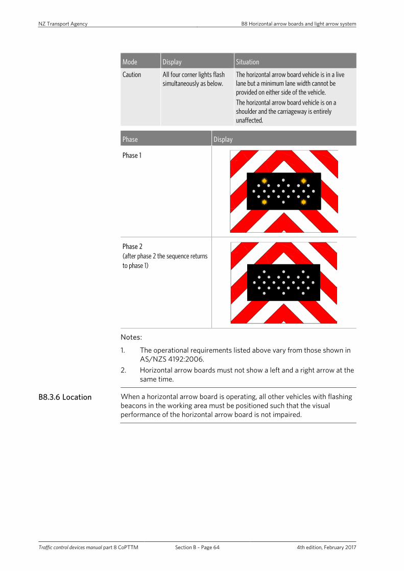
NZ Transport Agency B8 Horizontal arrow boards and light arrow system
Traffic control devices manual part 8 CoPTTM Section B – Page 64 4th edition, February 2017
Mode Display Situation
Caution All four corner lights flash simultaneously as below.
The horizontal arrow board vehicle is in a live lane but a minimum lane width cannot be provided on either side of the vehicle. The horizontal arrow board vehicle is on a shoulder and the carriageway is entirely unaffected.
Phase Display
Phase 1
Phase 2 (after phase 2 the sequence returns to phase 1)
Notes:
1. The operational requirements listed above vary from those shown in AS/NZS 4192:2006.
2. Horizontal arrow boards must not show a left and a right arrow at the same time.
B8.3.6 Location When a horizontal arrow board is operating, all other vehicles with flashing beacons in the working area must be positioned such that the visual performance of the horizontal arrow board is not impaired.

NZ Transport Agency B9 Advance warning variable message sign (AWVMS)
Traffic control devices manual part 8 CoPTTM Section B – Page 65 4th edition, February 2017
B9 Advance warning variable message sign (AWVMS)
B9.1.1 Types of variable message signs (VMS)
There are two types of variable message signs (VMS):
• advance warning variable message sign (AWVMS) - covered in this section
• standard VMS - covered in the NZTA’s P37 Specifications for mobile variable message signs (a draft of which is available on the NZTA’s website).
The AWVMS is used in conjunction with the LAS on level 2 and 3 state highways.
B9.1.2 About the AWVMS
The AWVMS is designed to provide advance warning for either mobile or static level 2/3 operations. It is used as a substitute for the tail pilot vehicle and is best suited for this role when mounted on a light commercial vehicle such as a ute.
The AWVMS must be carried on either a class NA light goods vehicle, or a TA very light trailer with limited weights and dimensions. See weights and dimensions specified below.
600 m
Light goods vehicle (Maximums)
Item Measurement
Kerb weight (tare weight) Max = 1950kg
Vehicle width (excluding mirrors) Less than 1910mm
Total vehicle length Less than 5250mm
Gross weight Less than 2750kg
Very light trailer (Maximums)
Item Measurement
Kerb weight (tare weight) Max = 750kg
Vehicle width (excluding mirrors) Less than 1500mm
Total vehicle length Less than 5000mm
Gross weight Less than 1500kg

NZ Transport Agency B9 Advance warning variable message sign (AWVMS)
Traffic control devices manual part 8 CoPTTM Section B – Page 66 4th edition, February 2017
B9.1.3 Specifications Detailed specifications for the AWVMS are listed in appendix E of the NZTA’s P37 Specifications for mobile variable message signs (a draft of which is available on the NZTA’s website).
The AWVMS must be capable of being operated from within the cab of its support vehicle. If it is to be used as a standard VMS it must comply with the relevant:
• legislation • sections of this manual, and • the NZTA’s P37 Specifications for mobile variable message signs (a draft of
which is available on the NZTA’s website).
B9.1.4 Height The bottom of the message panel must be positioned a minimum of 600mm above the ground surface.
B9.1.5 Tailboard The tailboard below the bottom text panel must be covered with red and white retro-reflective stripes (see the two options below).
Option 1
Option 2
B9.1.6 Effective dates
AWVMS may be used on level 2 and 3 state highways from 1 December 2008.
All new NZTA contracts awarded, for level 2 and 3 roads, from 1 July 2010 must use this style of AWVMS.
All NZTA contracts for level 2 and 3 roads from 1 July 2012 must use this style of AWVMS.

NZ Transport Agency B10 Mobile variable message sign (VMS)
Traffic control devices manual part 8 CoPTTM Section B – Page 67 4th edition, February 2017
B10 Mobile variable message sign (VMS)
B10.1.1 Mobile variable message signs (VMSs)
Mobile VMS may be used, where they can be justified, instead of large temporary traffic information signs. They have particular value where messages, including a blank sign, are required to be changed throughout the course of the work. They are an additional form of traffic management and must not be used to replace the normal signs or devices used for TTM.
Mobile VMS must be located in a similar position to an equivalent conventional temporary traffic sign. Signs must be located behind an approved delineation device or be protected by an approved barrier system or a non-gating re-directive crash attenuator.
B10.1.2 Types of variable message signs (VMSs)
There are a number of different types of VMS, with different applications. Each type is briefly described below:
• AWVMS – Mounted on a small utility vehicle or small trailer. Used for: – taking the place of a tail pilot in mobile operations – setting up a worksite for a static operation – providing additional information for a static operation
• Mobile VMS – Mounted on a trailer. Used as a relocatable sign providing information ahead of worksites, blockages diversions, etc. While in operation it is stationary
• Regional VMS – Mounted (usually) on a fixed support structure beside high volume urban or rural roads. Used for: – incident management, diversions, delays, closures – adverse road or driving conditions
• Advanced Traffic Management System VMS – Mounted on overhead gantries above motorways. Used for similar applications to the regional VMS.
B10.1.3 Design The NZTA has established design specifications that all new VMS and mobile VMS must comply with the NZTA’s P37 Specifications for mobile variable message signs (a draft of which is available on the NZTA’s website).

NZ Transport Agency B10 Mobile variable message sign (VMS)
Traffic control devices manual part 8 CoPTTM Section B – Page 68 4th edition, February 2017
B10.1.4 Messages and operation
The NZTA has established three levels of documentation relating to the operation of all new and existing mobile, regional and ATMS VMSs. These comprise the following:
1. The NZTA’s P34 Variable message sign national operating policy (in press)
This national document outlines the overall operating policy relating to the control of messages on the NZTA’s VMS and mobile VMS. It covers motorway, urban and rural locations, and has important links to the national operating procedure described below. Please refer to this document for direction on all policy aspects, including:
• all message applications • responding to emergency services requests • blanking of signs • verification of information • whether the state highway number (eg SH1) should be included • a VMS’s boundary of influence.
2. The NZTA’s P35 Variable message sign national operating procedure (in press)
This is a national document that addresses the operating procedures governing the NZTA’s VMS and mobile VMS. It contains a menu of standard messages and outlines the best practice processes used to compose messages. The national operating procedure sits below and is consistent with the national operating policy.
3. Regional schedules (in press)
These regional documents contain contact details of authorised consultants and contractors, approved message wording for commonly occurring events, frequently used local place names, and identify linked VMS for each common incident location.
They also include the type of detailed information required for maintenance or asset management purposes.
The collation and updating of these schedules is the responsibility of each region.

NZ Transport Agency B11 Truck-mounted attenuator (TMA)
Traffic control devices manual part 8 CoPTTM Section B – Page 69 4th edition, February 2017
B11 Truck-mounted attenuator (TMA)
B11.1 Introduction
A TMA generally consists of an energy absorption cartridge, a rigid back-up and a steel support structure that attaches the crash cushion to the truck.
Their purpose is to evenly and gradually dissipate the kinetic energy of an impacting vehicle.
TMAs also prevent an impacting vehicle from under-riding the truck body, which can result in shearing the top off the impacting vehicle at the bonnet line.
B11.1.1 National Cooperative Highway Research Programme (NCHRP) report 350
TMAs must be certified for compliance with NCHRP report 350 tests 50 and 51. The standard for roads with a speed limit in excess of 70km/h is test level 3. This has yet to be introduced as a requirement.
TL2 is the basic test level for TMAs and they must meet this performance requirement. With positive TTM, TL2 has been shown to be effective for crashes at speeds greater than 70km/h.
Note that the compliance rating for TMAs must be displayed on both sides of the unit and at the truck-mounting end of the unit, in black 100mm-high lettering and reading as NCHRP 350: TL-2.
B11.1.2 Support vehicles
All support vehicles equipped with a TMA must:
• meet the minimum vehicle weight for the type of attenuator as detailed in the New Zealand register of compliant TMA systems, which is available on the NZTA’s website
• meet all vehicle requirements recommended by the manufacturer of the TMA
• be legally permitted to travel on the road. Special approval may, however, need to obtained from the NZTA for some TMAs, eg an over-width or over-length permit, and
• have fitted, as a minimum, a standard three-point seat belt for each person in the TMA cab.
B11.1.3 Application TMAs are to be used on all levels of roads where required. Refer to sections C18 Temporary road safety barrier systems for static worksites and section D5 Mobile closures operational requirements for mobile operations.
All TMAs must at least comply with the requirements of NCHRP 350 TL 2 when used on roads with a permanent posted speed limit greater than 70km/h.

NZ Transport Agency B11 Truck-mounted attenuator (TMA)
Traffic control devices manual part 8 CoPTTM Section B – Page 70 4th edition, February 2017
B11.2 Rear panel of attenuator vehicle
B11.2.1 Introduction TMAs need to be highly visible and instantly recognisable.
For this reason, the red and white rear panel has been adopted, based on proven performance, to highlight the vehicle relative to its surroundings.
It is recommended that all RCAs adopt this policy for level 3 roads.
B11.2.2 Effective dates
B11.2.2.1 New TMA
TMA vehicles constructed after 1 July 2010 for use on level 2 and 3 roads must be fitted with the red and white colour and layout detailed in this section.
B11.2.2.2 Existing TMA
For use on Level 2 and 3 state highways
For all existing TMA, rear panels must comply by 1 July 2012.
For use on roads other than state highways
The rear panels of existing TMA in use on level 3 roads must be retrofitted to comply by 1 July 2012 It is recommended that the rear panel of existing TMA used on level 2 roads are retrofitted to comply.

NZ Transport Agency B11 Truck-mounted attenuator (TMA)
Traffic control devices manual part 8 CoPTTM Section B – Page 71 4th edition, February 2017
B11.2.3 Specification
Colour Primary strip – Red reflective class 1 retro-reflective.
Alternate strip – White reflective class 1 retro-reflective.
Height The overall height of the panel must not exceed 4.25m above the road. The lower 500mm of the panel will need to be installed on the rear of the TMA to remain under the maximum height specified in law.
LAS Refer to subsection B8.2.3 Specifications for LAS specifications.
Enlarged RD6L/R (RG-17/34)
1500mm diameter (± 50mm).
Xenon lights 340mm minimum diameter Xenon lights are to be installed in the top left and top right corners of the panel as per the drawing of a TMA for level 2 and 3 roads on the following page.
Equipment control The rear panel must have a device installed to ensure that the arrow board and the RD6L are always aligned. A display must be visible to the operator to confirm orientation.
Deck-mounted up-lighting
A white up-light with a minimum output of 50 watt is to be attached to the deck to adequately illuminate the RD6L/R.
Amber-flashing beacons One, preferably two, amber flashing beacons must be visible to the rear of the vehicle until such time as the LAS is fully deployed and the xenon lights are fully operational and at the correct height.
Organisations’ signage or logos
Must not be installed on the rear panel of the TMA.

NZ Transport Agency B11 Truck-mounted attenuator (TMA)
Traffic control devices manual part 8 CoPTTM Section B – Page 72 4th edition, February 2017
2200
500
3600
150
150 360 360
500
500
150036
036
0
360
(All measurements are in millimetres)
+ +

NZ Transport Agency B12 Temporary road safety barriers
Traffic control devices manual part 8 CoPTTM Section B – Page 73 4th edition, February 2017
B12 Temporary road safety barriers
B12.1.1 General All temporary road safety barrier products must comply with the performance requirements of this section.
Section C18 Temporary road safety barrier systems provides direction and guidance for the design, selection and use of barrier systems and end treatments. The prime document is NZTA M23 Specification for road safety barrier systems.
Note: This section and section C18 Temporary road safety barrier systems cover the requirements for temporary road safety barrier systems used in New Zealand.
The NZTA M23: Specification for road safety barrier systems cover the requirements for permanent and temporary road safety barrier systems used in New Zealand.
B12.1.2 Performance standards
All temporary road safety barrier systems must be approved by the NZTA National Traffic and Safety Manager.
This approval will require that the product has complied or been deemed to comply (by the NZTA) with the NCHRP report 350 performance levels. The performance levels for the containment of crash impact energy are based on a 2000kg vehicle impacting the barrier at an angle of 25 degrees, at a specified speed.
From 1 November 2012 the NZTA has adopted the AASHTO Manual for Assessing Safety Hardware (MASH) as the nominal standard for road safety hardware systems installed on the state highway network.
From this date the NZTA requires that MASH testing results be used as the primary performance criteria in promoting any road safety hardware system.
This section of CoPTTM is currently under revision to align it to the new standard. Please address any enquiries in relation to this notification to the National Manager Traffic and Safety.
Table below summarises the required barrier system performance test levels for the operating speed of adjacent traffic.
Barrier system performance levels
Test level Operating speed
1 50km/h or less
2 50km/h to 70km/h
3 greater than 70km/h
Temporary road safety barrier hardware must meet or exceed the test level required for the operating speed of adjacent traffic.

NZ Transport Agency B12 Temporary road safety barriers
Traffic control devices manual part 8 CoPTTM Section B – Page 74 4th edition, February 2017
B12.1.3 Approved temporary road safety barrier hardware
Only the road safety barrier hardware listed in the NZTA M23: Specification for road safety barrier systems appendices A and B is approved for use.
Any road safety barrier hardware not listed must be submitted to the NZTA National Traffic and Safety Manager for review and approval on a project or site specific basis.
The end treatments listed in appendix B of NZTA M23: Specification for road safety barrier systems are approved for temporary road safety barrier use.
Generally, different types of barrier systems must not be mixed without approved transitions.
The transitions listed in appendices A and B of NZTA M23: Specification for road safety barrier systems are approved for temporary road safety barrier use.
All products must be used in accordance with the manufacturer’s or supplier’s installation guidelines, including, but not limited, to the use of approved jointing and anchoring systems, and approved end treatments. All components must comply with the drawings and specifications.
B12.1.4 Channelling traffic
The NZTA M23: Specification for road safety barrier systems compliant barrier systems that are used to channel traffic must be conspicuous.
Complying plastic water-filled barrier systems that delineate traffic must be made conspicuous through having coloured sections. These colours may include orange, red and yellow.
Concrete or galvanised barrier systems must have either a natural concrete or galvanised face. If this is not possible they must have coloured sections as above.
Barrier systems must be fitted with reflective markers (chevrons) as shown over the page.

NZ Transport Agency B12 Temporary road safety barriers
Traffic control devices manual part 8 CoPTTM Section B – Page 75 4th edition, February 2017
Fluorescent orange
(Class 1 minimum)Fluorescent orange (Class 1 minimum) 150mm
Black
195mm
50mm
135mm
200mm
These are to be fitted along the top of the barrier as shown below.
Cross-Section
Portable Barrier
Retro-Reflective Chevron
Plan View
(Note end treatments not shown)
Retro-reflective chevrons at 10m centres
Portable Barrier
The chevron must consist of a fluorescent orange arrowhead on a rectangular black background 150mm x 200mm. The chevron must point to the side of the barrier that traffic is to pass. Chevrons must be placed at 10m centres along the barrier.

NZ Transport Agency B12 Temporary road safety barriers
Traffic control devices manual part 8 CoPTTM Section B – Page 76 4th edition, February 2017
B12.1.5 Visibility screens
Visibility screens are used to help prevent motorists being distracted by the works to facilitate improved and safer traffic conditions.
Visibility screens:
• Must be opaque (eg shade cloth, corrugated plastic or corriboard or other similar frangible materials). Rigid materials are not to be used unless it can be demonstrated (by crash testing or similar means) that such material will not cause injury when impacted
• Must provide a continuous screen a minimum of 2m in height above the pavement
• Must be designed to be attached to the rear of a temporary barrier or be free standing
• Must have a smooth and visually uncluttered surface of uniform colour. The same surface and colour must be used for the whole system.
The frames supporting visibility screens must be manufactured in such a manner so as not to present a hazard to worker, pedestrians or vehicle occupants when impacted.
All joints must be welded or similarly connected. Mechanical fixings (pipe clamp, bolted joints etc.) are not to be used. All tube bends or frame corners must have a radius of greater than 100mm.
Visibility screens and their supporting structures must be capable of accommodating all environmental loads imposed during normal operating conditions including wind loads and the wind load generated from all passing vehicles. Under such imposed loads the screens are not to move out of line or move in any way that may distract motorists.
No advertising or corporate marketing may be applied to a visibility screen. A single corporate logo not exceeding the maximum allowed under subsection B4.1.2 Area requirements for signs may be applied in the upper right-hand corner of the visibility screen.
B12.1.6 Application All barrier systems and end treatments must comply with the above requirements for all levels of roads.

NZ Transport Agency B13 Temporary speed humps
Traffic control devices manual part 8 CoPTTM Section B – Page 77 4th edition, February 2017
B13 Temporary speed humps
B13.1.1 General Speed hump systems are designed to ensure that road users slow to the required speed at a road works site. There are special conditions under which these may be used. These are detailed in subsection C10.5 Temporary speed humps.
B13.1.2 Approval Speed hump systems must be approved by the NZTA before use.
Details of testing criteria and independent testing are available from the NZTA:
Senior Traffic and Safety Engineer (CoPTTM) NZTA National Office Private Bag 6995 Wellington 6141 Phone +64 4 894 6355.
A register of compliant systems is available on the NZTA website.
New approvals will be added to the register as they pass testing. Testing is to be undertaken at own expense.
B13.1.3 Physical characteristics
Dimensions:
• Height – less than 40mm (+10mm tolerance). • Length – 3m or longer. • Width – less than 500mm. • Rise initial step no greater than 25mm, top profile curved. • Colour – a bright, fluorescent type colour, orange is preferred but yellow
may be used. • Retro-reflectivity/lighting – at night they must be clearly visible by using
either retro-reflective means or illumination. This is a legal requirement covered by the TCD Rule, section 7.9.

NZ Transport Agency B14 Warning systems
Traffic control devices manual part 8 CoPTTM Section B – Page 78 4th edition, February 2017
B14 Warning systems
B14.1 Flashing beacons
B14.1.1 General
Flashing or revolving amber beacons refer to roof mounted devices which consist of a light, encapsulated in a casing and may either flash (strobe) or appear to flash when circled by a rotating reflector. The beacon(s) are to be mounted on a vehicle in such positions as to give a 360° uninterrupted view in the horizontal plane.
Note: Vehicle hazard warning lights are not beacons.
B14.1.1.1 Land transport Rule: Vehicle lighting 2004
All flashing beacons used in New Zealand must comply with section 11 of the Land Transport Rule: Vehicle lighting 2004.
B14.1.1.2 ECE Regulation 65
The flash conditions, the amber colour coordinates and the light output of the beacon must comply with the criteria specified below which was identified from within ECE Regulation 65. Compliance with these conditions must be contingent on certification obtained from an IANZ accredited laboratory.
Note: The light output conditions permit beacons with a single light output level as well as those having dual (night/day) light output levels.
B14.1.2 Specification
Flash Rate
Colour amber
Rotating or flashing sources
Frequency f(Hz)
max 4
min 2
“ON” time (sec) max 0.4f
“OFF” time (sec) min 0.1

NZ Transport Agency B14 Warning systems
Traffic control devices manual part 8 CoPTTM Section B – Page 79 4th edition, February 2017
Light Output: (Table values are in candelas)
Colour - amber
Minimum value of the effective luminous intensity within the specified vertical angles and a horizontal angle of 360° around the reference axis.
0° By day 230
By night 100
+ 4° By day -
By night -
+ 8° By day 170
By night 70
Maximum value of the effective luminous intensity
Inside
+ 2°
By day 1,700
By night 700
Inside
+ 8°
By day 1,500
By night 600
Outside the above areas
By day 1,000
By night 300
Chromaticity
The trichromatic coordinates of light emitted through the filters used for special amber warning lamps shall lie within the following x and y boundaries of the CIE 1931 chromaticity diagram [reference CIE 15 – Colorimetry:2004):
Limit towards green: y < x – 0.120
Limit towards red: y > 0.390
Limit towards white: y > 0.790 – 0.670x

NZ Transport Agency B14 Warning systems
Traffic control devices manual part 8 CoPTTM Section B – Page 80 4th edition, February 2017
B14.2 Xenon warning lights
B14.2.1 General The purpose of the xenon warning lights is to give advance warning to alert approaching road users. Lights must be fitted in accordance with the CoPTTM-specified height and alignment specifications.
Xenon warning lights are not intended to be used on level LV and level 1 roads, unless they are fitted to AWVMS signs or the latest TMA display in accordance with CoPTTM.
It is recommended that all RCAs adopt xenon lights for level 2 and 3 roads.
B14.2.2 Effective date All TMAs used on level 2 and 3 state highways must be fitted with complying xenon warning lights by 1 July 2012.
It is recommended any new vehicle be fitted with xenon warning lights.
Level 2 and 3
All new NZTA contracts awarded from 1 July 2010 will require xenon warning lights.
Full implementation on level 2 and 3 state highways is required by 1 July 2012.
B14.2.3 Specification The xenon warning lights must comply with EN12352:2006.
The following details are the values for lights complying with EN12352:2006.
Class of warning light – L9M (Xenon)
Characteristic Requirements
Area of light emitting surface (cm2 ) >= 700
Diameter of light emitting surface (mm) minimum >= 300 (340mm desirable)
Angle range - horizontal +1.5° to -1.5°
Angle range - vertical +1.5° to -1.5°
Luminous intensity (cd) for nominal voltage:
• IRmin [minimum effective luminous intensity measured on the reference axis]
2000
• IAmax [maximum effective luminous intensity measured at any point within angle range]
8000

NZ Transport Agency B14 Warning systems
Traffic control devices manual part 8 CoPTTM Section B – Page 81 4th edition, February 2017
B14.2.3.1 Height
Minimum height of 3.5m to the centre of the light. Maximum clear height of 4.25m to the top of the light above the ground surface.
B14.2.3.2 Orientation
The reference axis of light emitted from each xenon warning lamp must not fall below a line parallel to the surface on which the vehicle is standing.
Note: EN12352:2006 uses the terms ‘principal axis’ and ‘reference axis’ which are defined as:
‘Principal axis is the horizontal axis which lies on the vertical plane of symmetry of the lens and passes through the photometric centre of the warning light when it is in its normal operating position.
Reference axis, unless otherwise specified by the manufacturer, is the axis of maximum luminous intensity within 2° in any direction of the principal axis’.
The specified height and orientation is required to ensure that road users are not unduly affected by the operation of the Xenon warning lights.