chapter 6c. temporary traffic control elements · page 1021 chapter 6c – temporary traffic...
TRANSCRIPT
California MUTCD 2014 Edition (FHWA’s MUTCD 2009 Edition, including Revisions 1 & 2, as amended for use in California)
Page 1021
Chapter 6C – Temporary Traffic Control Elements November 7, 2014 Part 6 – Temporary Traffic Control
CHAPTER 6C. TEMPORARY TRAFFIC CONTROL ELEMENTS
Section 6C.01 Temporary Traffic Control Plans Support:
01 A TTC plan describes TTC measures to be used for facilitating road users through a work zone or an incident area. TTC plans play a vital role in providing continuity of effective road user flow when a work zone, incident, or other event temporarily disrupts normal road user flow. Important auxiliary provisions that cannot conveniently be specified on project plans can easily be incorporated into Special Provisions within the TTC plan.
02 TTC plans range in scope from being very detailed to simply referencing typical drawings contained in this Manual, standard approved highway agency drawings and manuals, or specific drawings contained in the contract documents. The degree of detail in the TTC plan depends entirely on the nature and complexity of the situation. Guidance:
03 TTC plans should be prepared by persons knowledgeable (for example, trained and/or certified) about the fundamental principles of TTC and work activities to be performed. The design, selection, and placement of TTC devices for a TTC plan should be based on engineering judgment.
04 Coordination should be made between adjacent or overlapping projects to check that duplicate signing is not used and to check compatibility of traffic control between adjacent or overlapping projects.
05 Traffic control planning should be completed for all highway construction, utility work, maintenance operations, and incident management including minor maintenance and utility projects prior to occupying the TTC zone. Planning for all road users should be included in the process.
06
the TTC process. Where existing pedestrian routes are blocked or detoured, information should be provided about alternative routes that are usable by pedestrians with disabilities, particularly those who have visual disabilities. Access to temporary bus stops, travel across intersections with accessible pedestrian signals (see Section 4E.09), and other routing issues should be considered where temporary pedestrian routes are channelized. Barriers and channelizing devices that are detectable by people with visual disabilities should be provided.
Provisions for effective continuity of accessible circulation paths for pedestrians should be incorporated into
Option: 07 Provisions may be incorporated into the project bid documents that enable contractors to develop an alternate
TTC plan. 08 Modifications of TTC plans may be necessary because of changed conditions or a determination of better
methods of safely and efficiently handling road users. Guidance: Standard:
09 This alternate or modified plan should shall have the approval of the Engineer or the Engineer’s designee of the public agency or authority having jurisdiction over the highway responsible highway agency prior to implementation. Guidance:
10 Provisions for effective continuity of transit service should be incorporated into the TTC planning process because often public transit buses cannot efficiently be detoured in the same manner as other vehicles (particularly for short-term maintenance projects). Where applicable, the TTC plan should provide for features such as accessible temporary bus stops, pull-outs, and satisfactory waiting areas for transit patrons, including persons with disabilities, if applicable (see Section 8A.08 for additional light rail transit issues to consider for TTC).
11 Provisions for effective continuity of railroad service and acceptable access to abutting property owners and businesses should also be incorporated into the TTC planning process.
Reduced Speed Limits in TTC Zones Guidance:
12 Reduced speed limits should be used only in the specific portion of the TTC zone where conditions or restrictive features are present. However, frequent changes in the speed limit should be avoided. A TTC plan
California MUTCD 2014 Edition (FHWA’s MUTCD 2009 Edition, including Revisions 1 & 2, as amended for use in California)
Chapter 6C – Temporary Traffic Control Elements November 7, 2014 Part 6 – Temporary Traffic Control
Page 1022
should be designed so that vehicles can travel through the TTC zone with a speed limit reduction of no more than 10 mph.
13 A reduction of more than 10 mph in the speed limit should be used only when required by restrictive features in the TTC zone. Where restrictive features justify a speed reduction of more than 10 mph, additional driver notification should be provided. The speed limit should be stepped down in advance of the location requiring the lowest speed, and additional TTC warning devices should be used.
14 Reduced speed zoning (lowering the regulatory speed limit) should be avoided as much as practical because drivers will reduce their speeds only if they clearly perceive a need to do so. Standard:
14a The justification for the reduced regulatory speed limit shall be documented in writing. Refer to CVC 21367 and 22362. Option: 14b Reduced speed limits in construction zones may be established by an engineering analysis, which may include a traffic and engineering survey. Support:
15 Research has demonstrated that large reductions in the speed limit, such as a 30 mph reduction, increase speed variance and the potential for crashes. Smaller reductions in the speed limit of up to 10 mph cause smaller changes in speed variance and lessen the potential for increased crashes. A reduction in the regulatory speed limit of only up to 10 mph from the normal speed limit has been shown to be more effective. Support:
16 See Section 2B.13 for Regulatory Speed Limit signs and Speed Zones. 17 See Section 6F.12 for WORK ZONE (G20-5aP) plaque and END WORK ZONE SPEED LIMIT (R2-12) sign. 18 CVC section 22362 gives the agency having jurisdiction over a highway the authority to regulate the speed of traffic to
provide protection for workers when at work on the roadway or within the right-of-way so close thereto as to be endangered by passing traffic.
19 CVC Section 21367 gives the agency having jurisdiction over a highway the authority to regulate the speed of traffic whenever the traffic would endanger the safety of workers or the work would interfere with or endanger the movement of traffic through the area. Guidance:
20 The need for a long-term reduced speed limit within a TTC zone should be a decision made during the project development process. The need for a short-term reduced speed limit within a TTC zone, such as a maintenance activity, should be determined in advance of planned maintenance activities.
Option: 21 If lowering speed limits for a short-term, such as a maintenance activity, signs lowering the speed limit by 10 mph or less
may be placed in work zones that are not protected by a positive barrier and involve workers on foot or on equipment. Guidance:
22 Reducing speed limits in TTC zones should be avoided if traffic speeds can be reduced by other means. Speed restrictions should be imposed on the public only when necessary for worker or public safety.
Standard: 23 Where traffic obstructions exist only during the hours of construction, the speed zone signs shall be covered
during non-working hours. Support:
24 CVC 22362 applies to "When Workers are Present" condition and signs need to be covered or removed when no work is in progress. As per CVC 21367, agency can "...regulate the movement of traffic...whenever the traffic would endanger the safety of workers or the work would interfere with or endanger the movement of traffic through the area." If obstructions would be present throughout the project duration the signs would not need to be covered or removed. This would also apply to situations where the construction work changes the highway configuration, curvature or elevation, making it necessary to post reduced speed limits. Option:
25 The Advisory Speed (W13-1P) plaque may be used in combination with various warning type signs to decrease speed at a particular location. See Section 6F.52
California MUTCD 2014 Edition (FHWA’s MUTCD 2009 Edition, including Revisions 1 & 2, as amended for use in California)
Chapter 6C – Temporary Traffic Control Elements November 7, 2014 Part 6 – Temporary Traffic Control
Page 1023
Guidance: 26 To preserve the effectiveness of the W13-1P plaque, it should not be used unless the condition to which it applies is
immediate and will be experienced by all motorists. Guidance:
27 Construction zone speed limits should be reduced in sequential stages and where overall reduction of 15 mph or more is required. The first stage of the sequence should be a reduction of 10 mph and the final stage reduction should be 10 mph or 5 mph, as necessary. Standard:
28 The reduced speed limit shall not be less than 25 mph. Refer to CVC 22362. Option:
29 As an example, if the project falls within an established 55 mph zone, and a 40 mph speed limit is considered necessary, it may be posted only if the approaching speed limits are lowered in two stages (i.e., first to a 45 mph speed limit followed by a reduction to the desired 40 mph.) Support:
30 Documentation for reducing speed limits in TTC zones are ordinarily issued for the entire length of the TTC zones in a project. This avoids the necessity and resulting delay of obtaining new documentation each time the speed restriction signs require relocation to fit the conditions. It is not the intention, however, that the entire length be posted for the duration of the project. Standard:
31 Speed limit signs for reduced speed limits shall be posted only in areas where the traveling public is affected by TTC operations. Standard:
32 Signs shall be used only during working hours and removed, or covered during non-working hours unless the movement of traffic through the TTC zone is affected during non-working hours as well. Refer to CVC 21367.
33 Signs shall be removed immediately following completion of the construction or change in the conditions for which they were installed. When the construction is completed or the speed restriction is no longer necessary, the formal speed zone orders shall be revoked.
Section 6C.02 Temporary Traffic Control Zones
Support: 01 A TTC zone is an area of a highway where road user conditions are changed because of a work zone, an
incident zone, or a planned special event through the use of TTC devices, uniformed law enforcement officers, or other authorized personnel.
02 A work zone is an area of a highway with construction, maintenance, or utility work activities. A work zone is typically marked by signs, channelizing devices, barriers, pavement markings, and/or work vehicles. It extends from the first warning sign or high-intensity rotating, flashing, oscillating, or strobe lights on a vehicle to the END ROAD WORK sign or the last TTC device.
03 An incident zone is an area of a highway where temporary traffic controls are imposed by authorized officials in response to a traffic incident (see Section 6I.01). It extends from the first warning device (such as a sign, light, or cone) to the last TTC device or to a point where road users return to the original lane alignment and are clear of the incident.
04 A planned special event often creates the need to establish altered traffic patterns to handle the increased traffic volumes generated by the event. The size of the TTC zone associated with a planned special event can be small, such as closing a street for a festival, or can extend throughout a municipality for larger events. The duration of the TTC zone is determined by the duration of the planned special event.
Section 6C.03 Components of Temporary Traffic Control Zones
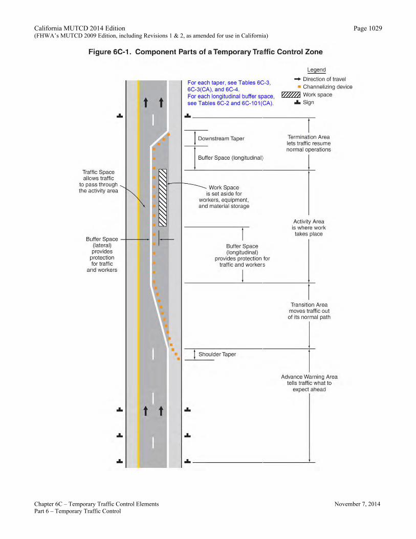
Support: 01 Most TTC zones are divided into four areas: the advance warning area, the transition area, the activity area,
and the termination area. Figure 6C-1 illustrates these four areas. These four areas are described in Sections 6C.04 through 6C.07.
California MUTCD 2014 Edition (FHWA’s MUTCD 2009 Edition, including Revisions 1 & 2, as amended for use in California)
Chapter 6C – Temporary Traffic Control Elements November 7, 2014 Part 6 – Temporary Traffic Control
Page 1024
Section 6C.04 Advance Warning Area Support:
01 The advance warning area is the section of highway where road users are informed about the upcoming work zone or incident area. Option:
02 The advance warning area may vary from a single sign or high-intensity rotating, flashing, oscillating, or strobe lights on a vehicle to a series of signs in advance of the TTC zone activity area. Guidance:
03 Typical distances for placement of advance warning signs on freeways and expressways should be longer because drivers are conditioned to uninterrupted flow. Therefore, the advance warning sign placement should extend on these facilities as far as 1/2 mile or more.
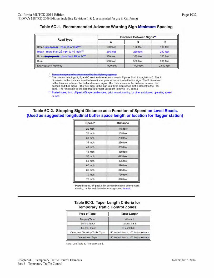
04 On urban streets, the effective placement of the first warning sign in feet should range from 4 to 8 times the speed limit in mph, with the high end of the range being used when speeds are relatively high. When a single advance warning sign is used (in cases such as low-speed residential streets), the advance warning area can be as short as 100 feet. When two or more advance warning signs are used on higher-speed streets, such as major arterials, the advance warning area should extend a greater distance (see Table 6C-1).
05 Since rural highways are normally characterized by higher speeds, the effective placement of the first warning sign in feet should be substantially longer—from 8 to 12 times the speed limit in mph. Since two or more advance warning signs are normally used for these conditions, the advance warning area should extend 1,500 feet or more for open highway conditions (see Table 6C-1).
06 The distances contained in Table 6C-1 are approximate, are intended for guidance purposes only, and should be applied with engineering judgment. These distances should be adjusted for field conditions, if necessary, by increasing or decreasing the recommended distances. Support:
07 The need to provide additional reaction time for a condition is one example of justification for increasing the sign spacing. Conversely, decreasing the sign spacing might be justified in order to place a sign immediately downstream of an intersection or major driveway such that traffic turning onto the roadway in the direction of the TTC zone will be warned of the upcoming condition. Option:
08 Advance warning may be eliminated when the activity area is sufficiently removed from the road users’ path behind a barrier, more than 2 feet behind the curb, or 15 feet or more from the edge of the traveled way so that it does not interfere with the normal flow.
Section 6C.05 Transition Area
Support: 01 The transition area is that section of highway where road users are redirected out of their normal path.
Transition areas usually involve strategic use of tapers, which because of their importance are discussed separately in detail. Standard:
02 When redirection of the road users’ normal path is required, they shall be directed from the normal path to a new path. Option:
03 Because it is impractical in mobile operations to redirect the road user’s normal path with stationary channelization, more dominant vehicle-mounted traffic control devices, such as arrow boards, portable changeable message signs, and high-intensity rotating, flashing, oscillating, or strobe lights, may be used instead of channelizing devices to establish a transition area.
Section 6C.06 Activity Area
Support: 01 The activity area is the section of the highway where the work activity takes place. It is comprised of the
work space, the traffic space, and the buffer space.

California MUTCD 2014 Edition (FHWA’s MUTCD 2009 Edition, including Revisions 1 & 2, as amended for use in California)
Chapter 6C – Temporary Traffic Control Elements November 7, 2014 Part 6 – Temporary Traffic Control
Page 1025
02 The work space is that portion of the highway closed to road users and set aside for workers, equipment, and material, and a shadow vehicle if one is used upstream. Work spaces are usually delineated for road users by channelizing devices or, to exclude vehicles and pedestrians, by temporary barriers. Option:
03 The work space may be stationary or may move as work progresses. Guidance:
04 Since there might be several work spaces (some even separated by several miles) within the project limits, each work space should be adequately signed to inform road users and reduce confusion. Support:
05 The traffic space is the portion of the highway in which road users are routed through the activity area. 06 The buffer space is a lateral and/or longitudinal area that separates road user flow from the work space or an
unsafe area, and might provide some recovery space for an errant vehicle. Guidance:
07 Neither work activity nor storage of equipment, vehicles, or material should occur within a buffer space. Option:
08 Buffer spaces may be positioned either longitudinally or laterally with respect to the direction of road user flow. The activity area may contain one or more lateral or longitudinal buffer spaces.
09 A longitudinal buffer space may be placed in advance of a work space. Guidance:
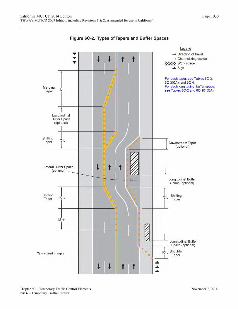
10 The longitudinal buffer space may should also be used to separate opposing road user flows that use portions of the same traffic lane, as shown in Figure 6C-2. Option:
11 If a longitudinal buffer space is used, the values shown in Table 6C-2 and Table 6C-101(CA) may be used to determine the length of the longitudinal buffer space. Support:
12 Typically, the buffer space is formed as a traffic island and defined by channelizing devices. 13 When a shadow vehicle, arrow board, or changeable message sign is placed in a closed lane in advance of a
work space, only the area upstream of the vehicle, arrow board, or changeable message sign constitutes the buffer space. Option:
14 The lateral buffer space may be used to separate the traffic space from the work space, as shown in Figures 6C-1 and 6C-2, or such areas as excavations or pavement edge drop-offs. A lateral buffer space also may be used between two travel lanes, especially those carrying opposing flows. Guidance:
15 The width of a lateral buffer space should be determined by engineering judgment. Option:
16 When work occurs on a high-volume, highly congested facility, a vehicle storage or staging space may be provided for incident response and emergency vehicles (for example, tow trucks and fire apparatus) so that these vehicles can respond quickly to road user incidents.
Section 6C.07 Termination Area
Support: 01 The termination area is the section of the highway where road users are returned to their normal driving path.
The termination area extends from the downstream end of the work area to the last TTC device such as END ROAD WORK signs, if posted. Option:
02 An END ROAD WORK sign, a Speed Limit sign, or other signs may be used to inform road users that they can resume normal operations.
03 A longitudinal buffer space may be used between the work space and the beginning of the downstream taper.
California MUTCD 2014 Edition (FHWA’s MUTCD 2009 Edition, including Revisions 1 & 2, as amended for use in California)
Page 1026
Chapter 6C – Temporary Traffic Control Elements November 7, 2014 Part 6 – Temporary Traffic Control
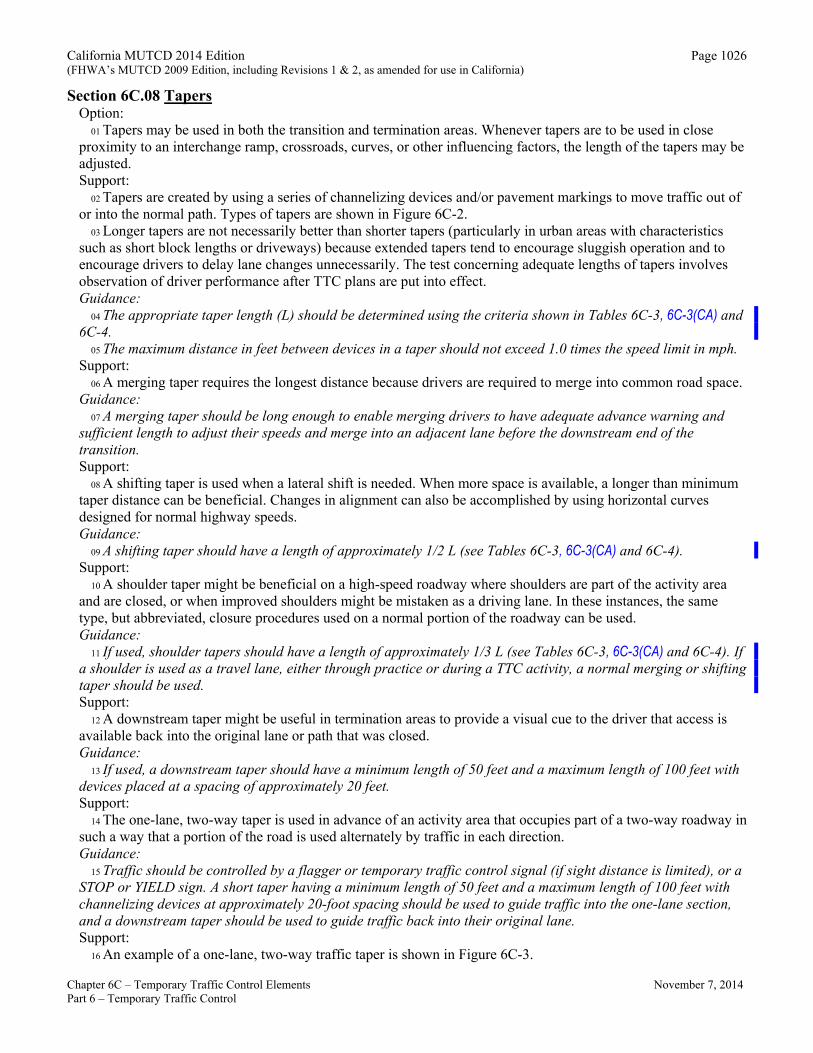
Section 6C.08 Tapers Option:
01 Tapers may be used in both the transition and termination areas. Whenever tapers are to be used in close proximity to an interchange ramp, crossroads, curves, or other influencing factors, the length of the tapers may be adjusted. Support:
02 Tapers are created by using a series of channelizing devices and/or pavement markings to move traffic out of or into the normal path. Types of tapers are shown in Figure 6C-2.
03 Longer tapers are not necessarily better than shorter tapers (particularly in urban areas with characteristics such as short block lengths or driveways) because extended tapers tend to encourage sluggish operation and to encourage drivers to delay lane changes unnecessarily. The test concerning adequate lengths of tapers involves observation of driver performance after TTC plans are put into effect. Guidance:
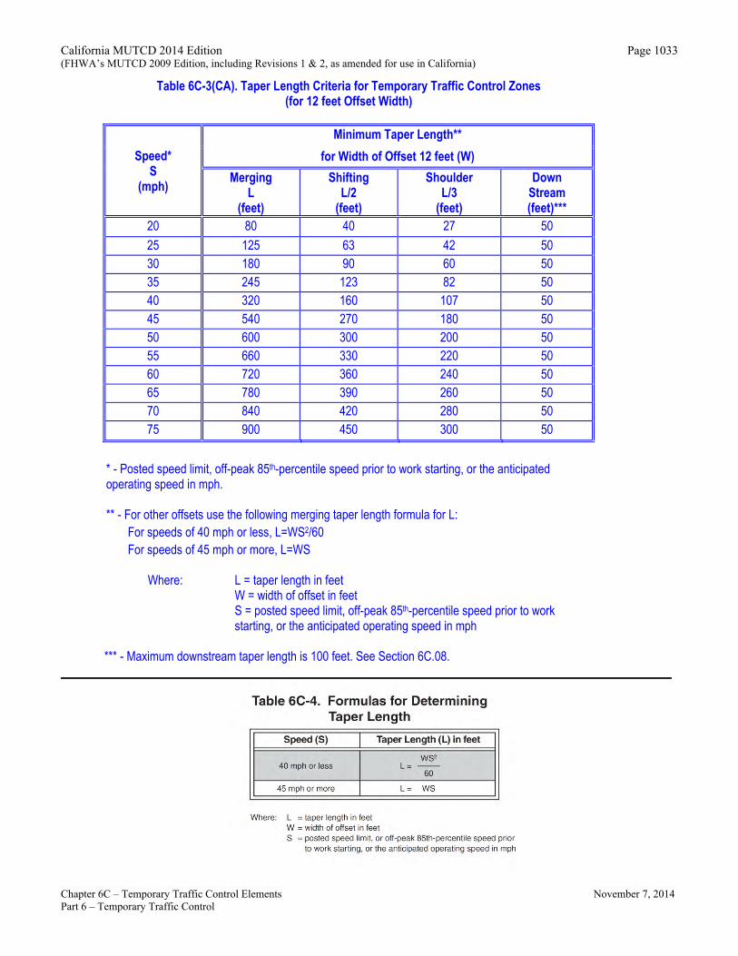
04 The appropriate taper length (L) should be determined using the criteria shown in Tables 6C-3, 6C-3(CA) and6C-4.
05 The maximum distance in feet between devices in a taper should not exceed 1.0 times the speed limit in mph. Support:
06 A merging taper requires the longest distance because drivers are required to merge into common road space. Guidance:
07 A merging taper should be long enough to enable merging drivers to have adequate advance warning and sufficient length to adjust their speeds and merge into an adjacent lane before the downstream end of the transition. Support:
08 A shifting taper is used when a lateral shift is needed. When more space is available, a longer than minimum taper distance can be beneficial. Changes in alignment can also be accomplished by using horizontal curves designed for normal highway speeds. Guidance:
09 A shifting taper should have a length of approximately 1/2 L (see Tables 6C-3, 6C-3(CA) and 6C-4). Support:
10 A shoulder taper might be beneficial on a high-speed roadway where shoulders are part of the activity area and are closed, or when improved shoulders might be mistaken as a driving lane. In these instances, the same type, but abbreviated, closure procedures used on a normal portion of the roadway can be used. Guidance:
11 If used, shoulder tapers should have a length of approximately 1/3 L (see Tables 6C-3, 6C-3(CA) and 6C-4). If a shoulder is used as a travel lane, either through practice or during a TTC activity, a normal merging or shifting taper should be used. Support:
12 A downstream taper might be useful in termination areas to provide a visual cue to the driver that access is available back into the original lane or path that was closed. Guidance:
13 If used, a downstream taper should have a minimum length of 50 feet and a maximum length of 100 feet with devices placed at a spacing of approximately 20 feet. Support:
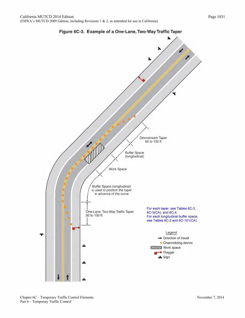
14 The one-lane, two-way taper is used in advance of an activity area that occupies part of a two-way roadway in such a way that a portion of the road is used alternately by traffic in each direction. Guidance:
15 Traffic should be controlled by a flagger or temporary traffic control signal (if sight distance is limited), or a STOP or YIELD sign. A short taper having a minimum length of 50 feet and a maximum length of 100 feet with channelizing devices at approximately 20-foot spacing should be used to guide traffic into the one-lane section, and a downstream taper should be used to guide traffic back into their original lane. Support:
16 An example of a one-lane, two-way traffic taper is shown in Figure 6C-3.
California MUTCD 2014 Edition (FHWA’s MUTCD 2009 Edition, including Revisions 1 & 2, as amended for use in California)
Chapter 6C – Temporary Traffic Control Elements November 7, 2014 Part 6 – Temporary Traffic Control
Page 1027
Guidance: 17 On State highways, Caltrans’ Standard Plans for Traffic Control Systems (Standard Plans T9 through T17) should be
used. See Section 1A.11 for information regarding this publication.
Section 6C.09 Detours and Diversions Support:
01 A detour is a temporary rerouting of road users onto an existing highway in order to avoid a TTC zone. Guidance:
02 Detours should be clearly signed over their entire length so that road users can easily use existing highways to return to the original highway. Support:
03 A diversion is a temporary rerouting of road users onto a temporary highway or alignment placed around the work area. Standard:
04 The detour route shall be evaluated for height, weight, and size restrictions. Appropriate signs shall be posted along the route to advise road users of any restrictions. Refer to CVC 21363 for detour signs. Option:
05 Advance signs or changeable message signs (CMS) may be necessary to give trucks an opportunity to turn around and retrace their path or select another route.
Section 6C.10 One-Lane, Two-Way Traffic Control
Standard: 01 Except as provided in Paragraph 5, when traffic in both directions must use a single lane for a limited
distance, movements from each end shall be coordinated. Guidance:
02 Provisions should be made for alternate one-way movement through the constricted section via methods such as flagger control, a flag transfer, a pilot car, traffic control signals, or stop or yield control.
03 Control points at each end should be chosen to permit easy passing of opposing lanes of vehicles. 04 If traffic on the affected one-lane roadway is not visible from one end to the other, then flagging procedures,
a pilot car with a flagger used as described in Section 6C.13, or a traffic control signal should be used to control opposing traffic flows. Option:
05 If the work space on a low-volume street or road is short and road users from both directions are able to see the traffic approaching from the opposite direction through and beyond the worksite, the movement of traffic through a one-lane, two-way constriction may be self-regulating. Support:
06 See Section 5A.01 and Section 6A.01 for definition of a low-volume road where paragraph 5 is applied.
Section 6C.11 Flagger Method of One-Lane, Two-Way Traffic Control Guidance:
01 Except as provided in Paragraph 2, traffic should be controlled by a flagger at each end of a constricted section of roadway. One of the flaggers should be designated as the coordinator. To provide coordination of the control of the traffic, the flaggers should be able to communicate with each other orally, electronically, or with manual signals. These manual signals should not be mistaken for flagging signals. Option:
02 When a one-lane, two-way TTC zone is short enough to allow a flagger to see from one end of the zone to the other, traffic may be controlled by either a single flagger or by a flagger at each end of the section. Guidance:
03 When a single flagger is used, the flagger should be stationed on the shoulder opposite the constriction or work space, or in a position where good visibility and traffic control can be maintained at all times. When good visibility and traffic control cannot be maintained by one flagger station, traffic should be controlled by a flagger at each end of the section.
California MUTCD 2014 Edition (FHWA’s MUTCD 2009 Edition, including Revisions 1 & 2, as amended for use in California)
Chapter 6C – Temporary Traffic Control Elements November 7, 2014 Part 6 – Temporary Traffic Control
Page 1028
Section 6C.12 Flag Transfer Method of One-Lane, Two-Way Traffic Control
Support: 01 The driver of the last vehicle proceeding into the one-lane section is given a red flag (or other token) and
instructed to deliver it to the flagger at the other end. The opposite flagger, upon receipt of the flag, then knows that traffic can be permitted to move in the other direction. A variation of this method is to replace the use of a flag with an official pilot car that follows the last road user vehicle proceeding through the section. Guidance:
02 The flag transfer method should be employed only where the one-way traffic is confined to a relatively short length of a road, usually no more than 1 mile in length. Standard:
01 This section is deleted for application and shall not be used in California. See section 6C.10, 6C.11, 6C.13, 6C.14, and 6C.15 for other methods of one-lane, two-way traffic control that are to be used in California.
Section 6C.13 Pilot Car Method of One-Lane, Two-Way Traffic Control
Option: 01 A pilot car may be used to guide a queue of vehicles through the TTC zone or detour.
Guidance: 02 The pilot car should have the name of the contractor or contracting authority prominently displayed.
Standard: 03 The PILOT CAR FOLLOW ME (G20-4) sign or PILOT CAR DO NOT PASS (R115(CA)) sign (see Section
6F.58) shall be mounted on the rear of the pilot vehicle. 04 A flagger shall be stationed on the approach to the activity area to control vehicular traffic until the
pilot vehicle is available. Option:
05 Two or more pilot cars may be used to guide two-way traffic through a particularly complex detour or TTC zone.
Section 6C.14 Temporary Traffic Control Signal Method of One-Lane, Two-Way Traffic Control Option:
01 Traffic control signals may be used to control vehicular traffic movements in one-lane, two-way TTC zones (see Figure 6H-12 and Chapter 4H).
Section 6C.15 Stop or Yield Control Method of One-Lane, Two-Way Traffic Control
Option: 01 STOP or YIELD signs may be used to control traffic on low-volume roads at a one-lane, two-way TTC zone
when drivers are able to see the other end of the one-lane, two-way operation and have sufficient visibility of approaching vehicles. Guidance:
02 If the STOP or YIELD sign is installed for only one direction, then the STOP or YIELD sign should face road users who are driving on the side of the roadway that is closed for the work activity area. Standard:
03 The approach to the side that is not closed shall be visible (for a distance equal to the safe passing sight distance for that approach) to the driver who must yield or stop. Support:
04 See Section 3B.02 and Figure 6H-11.
California MUTCD 2014 Edition (FHWA’s MUTCD 2009 Edition, including Revisions 1 & 2, as amended for use in California)
Page 1029
Chapter 6C – Temporary Traffic Control Elements November 7, 2014 Part 6 – Temporary Traffic Control
Figure 6C-1. Component Parts of a Temporary Tra1ffic Control Zone
Traffic Space allows traffic
to pass through the activity area
t
Buffer Space -+---l (lateral) provides
protection for traffic
and workers
t
t
,_
t
For each taper, see Tables 6C-3, 6C-3(CA), and 6C-4. For each longitudinal buffer space, see Tables 6C-2 and 6C-101 (CA) .
Legend
- Direction of travel • Channelizing device
.&. Sign
.&. _________________________________ .-
1 Downstream Taper
I """•' Spaoe (longrt"di"'l)
Work Space is set aside for
workers, equipment, and material storage
Buffer Space (longitudinal)
provides protection for traffic and workers
f Shoulder Taper
Termination Area lets traffic resume normal operations
j
Activity Area is where work takes place
Transition Area moves traffic out of its normal path
Advance Warning Area tells traffic what to
expect ahead
California MUTCD 2014 Edition (FHWA’s MUTCD 2009 Edition, including Revisions 1 & 2, as amended for use in California)
Page 1030
-
Chapter 6C – Temporary Traffic Control Elements November 7, 2014 Part 6 – Temporary Traffic Control
Figure SC-2. Types of Tapers and Buffer Spaces
Merging Taper L
Longitudinal Buffer Space
(optional)
! t Shifting
112 L
"'' "'' "''
Taper l
Lateral Buffer Space (optional)
Shifting Taper
l 1/2 L
1
l 4S ft*
1
*S = speed in mph
t t
t
•
Legend
- Direction of travel • Channelizing device
.a. Sign
For each taper, see Tables 6C-3, 6C-3(CA), and 6C-4. For each longitudinal buffer space, see Tables 6C-2 and 6C-101 (CA).
l 1/2 L
1
Downstream Taper (optional)
Longitudinal Buffer Space (optional)
Shifting Taper
+------'-- Longitudinal Buffer Space (optional)
t 1/3 L Shoulder
' Taper -----'---... ... ...
California MUTCD 2014 Edition (FHWA’s MUTCD 2009 Edition, including Revisions 1 & 2, as amended for use in California)
Chapter 6C – Temporary Traffic Control Elements November 7, 2014 Part 6 – Temporary Traffic Control
Page 1031
Figure 6C-3. Example of a One-Lane, Two-Way Traffic Taper
"'" ......
I
Buffer Space (longitudinal) is used to position the taper
in advance of the curve
One-Lane, Two-Way Traffic Taper 50 to 100ft
_ j
...
...
...
For each taper, see Tables SC-3, 6C-3(CA), and SC-4. For each longitudinal buffer space, see Tables 6C-2 and 6C-101 (CA) .
Legend
- Direction of travel • Channelizing device
...... Flagger olo Sign
California MUTCD 2014 Edition (FHWA’s MUTCD 2009 Edition, including Revisions 1 & 2, as amended for use in California)
Chapter 6C – Temporary Traffic Control Elements November 7, 2014 Part 6 – Temporary Traffic Control
Page 1032
____________________________________________________________________________________________
____________________________________________________________________________________________
____________________________________________________________________________________________
California MUTCD 2014 Edition Page 1033 (FHWA’s MUTCD 2009 Edition, including Revisions 1 & 2, as amended for use in California)
Table 6C-3(CA). Taper Length Criteria for Temporary Traffic Control Zones (for 12 feet Offset Width)
Speed* S
(mph)
Minimum Taper Length**
for Width of Offset 12 feet (W)
MergingL
(feet)
ShiftingL/2
(feet)
Shoulder L/3
(feet)
Down Stream (feet)***
20
80
270
40 27 50
25
125 63 42 5030 180 90 60 5035 245 123 82 5040 320 160 107 5045 540 180 5050 600 300 200 5055
660 330 220 5060
720 360 240 5065 780 390 260 5070 840 420 280 5075 900 450 300 50
* - Posted speed limit, off-peak 85th-percentile speed prior to work starting, or the anticipated operating speed in mph.
** - For other offsets use the following merging taper length formula for L: For speeds of 40 mph or less, L=WS2/60 For speeds of 45 mph or more, L=WS
Where: L = taper length in feet W = width of offset in feet S = posted speed limit, off-peak 85th-percentile speed prior to work starting, or the anticipated operating speed in mph
*** - Maximum downstream taper length is 100 feet. See Section 6C.08.
Chapter 6C – Temporary Traffic Control Elements November 7, 2014 Part 6 – Temporary Traffic Control
California MUTCD 2014 Edition Page 1034 (FHWA’s MUTCD 2009 Edition, including Revisions 1 & 2, as amended for use in California)
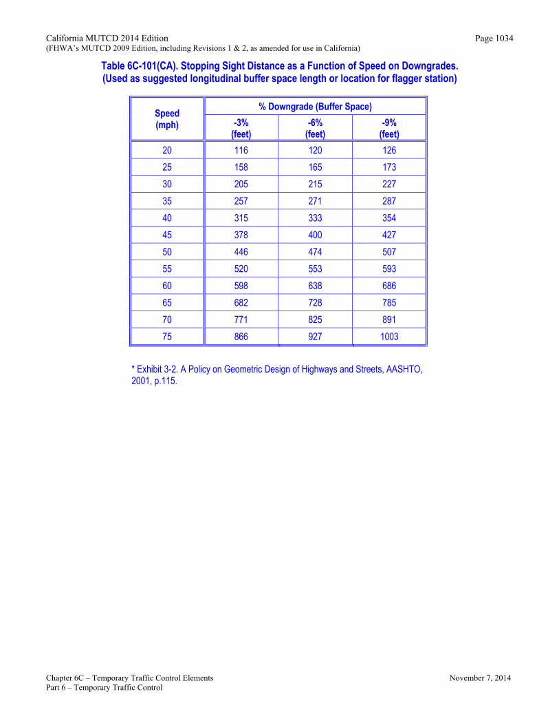
Table 6C-101(CA). Stopping Sight Distance as a Function of Speed on Downgrades. (Used as suggested longitudinal buffer space length or location for flagger station)
Speed(mph)
% Downgrade (Buffer Space)
-3% (feet)
-6% (feet)
-9% (feet)
20
116 120 126
25 158 165
173
30 205 215 227
35 257 271 287
40 315 333
354
45 378 400 427
50 446 474 507
55 520 553
593
60 598 638 686
65 682 728 785
70 771 825 891
75 866 927 1003
* Exhibit 3-2. A Policy on Geometric Design of Highways and Streets, AASHTO, 2001, p.115.
Chapter 6C – Temporary Traffic Control Elements November 7, 2014 Part 6 – Temporary Traffic Control