concise handbook for temporary traffic control
TRANSCRIPT

INDIANA Local Technical Assistance Pro gram
CONCISE HANDBOOK FORTEMPORARY TRAFFIC CONTROL
Construction, Maintenance,and Utility Operations
2017SP-4
Indiana Local Technical Assistant Program3000 Kent Avenue., Suite C2-118, West Lafayette, Indiana 47906-1075765.494.2164 or 800.428.7639 toll free in [email protected]/inltap
Engineering

This page intentionally left blank
CONCISE HANDBOOK FORTEMPORARY TRAFFIC CONTROL
Construction, Maintenance, and Utility Operations2017SP-4
Indiana LTAP CenterPurdue University3000 Kent Avenue, Suite C2-118West Lafayette, IN 47906-1075Telephone: 765.494.2164Toll Free in Indiana: 800.428.7639Fax: 765.496.1176Email: [email protected]: www.purdue.edu/inltap

This handbook is based upon one created by the Ohio Department of Transportation, Guidelines for Traffic Control in Work Zones. Indiana LTAP expresses thanks to ODOT for their permission to reprint this material.
While every effort has been made to assure that this information is current and complete, neither Indiana LTAP nor the Ohio Department of Transportation are responsible for any errors or inaccuracies. Please consult the Indiana Manual on Uniform Traffic Control Devices (IMUTCD) to confirm all information and for additional information on traffic control. The IMUTCD can be found at:http://www.in.gov/dot/div/contracts/design/mutcd/mutcd.html

2017
Temporary Traffic ControlGuidelines for Construction, TrafficMaintenance, and Utility Operations
Table of Contents
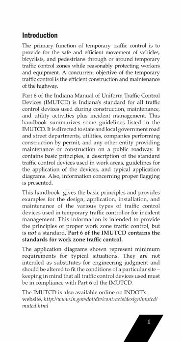
Introduction...................................................................1
Major Traffi c Control Considerations..........................2
Fundamental Principles...............................................3
Component Parts of a TemporaryTraffi c Control Zone.....................................................4
Defi nitions......................................................................5
Tapers..............................................................................6
Flagging..........................................................................7
Arrow Boards..............................................................11
Channelizing Devices.................................................12
Warning Lights............................................................14
Nightt ime Operation..................................................14
Signs..............................................................................15
Summary of Layout Dimensions..............................17
Typical Application Diagrams..................................18
Flagger’s Checklist......................................................52
Supervisor’s Checklist...............................................53
Suggested Traffi c Controlfor Work Zone Activities...........................................54
Typical Application Matrix.......................................55
Contact Information and Training...........................57
1
IntroductionThe primary function of temporary traffi c control is to provide for the safe and effi cient movement of vehicles, bicyclists, and pedestrians through or around temporary traffi c control zones while reasonably protecting workers and equipment. A concurrent objective of the temporary traffi c control is the effi cient construction and maintenance of the highway.
Part 6 of the Indiana Manual of Uniform Traffi c Control Devices (IMUTCD) is Indiana’s standard for all traffi c control devices used during construction, maintenance, and utility activities plus incident management. This handbook summarizes some guidelines listed in the IMUTCD. It is directed to state and local government road and street departments, utilities, companies performing construction by permit, and any other entity providing maintenance or construction on a public roadway. It contains basic principles, a description of the standard traffi c control devices used in work areas, guidelines for the application of the devices, and typical application diagrams. Also, information concerning proper fl agging is presented.
This handbook gives the basic principles and provides examples for the design, application, installation, and maintenance of the various types of traffi c control devices used in temporary traffi c control or for incident management. This information is intended to provide the principles of proper work zone traffi c control, but is not a standard. Part 6 of the IMUTCD contains the standards for work zone traffi c control.
The application diagrams shown represent minimum requirements for typical situations. They are not intended as substitutes for engineering judgment and should be altered to fi t the conditions of a particular site – keeping in mind that all traffi c control devices used must be in compliance with Part 6 of the IMUTCD.
The IMUTCD is also available online on INDOT’s website, http://www.in.gov/dot/div/contracts/design/mutcd/mutcd.html
2
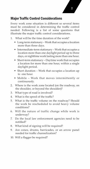
Major Traffic Control ConsiderationsEvery work zone situation is diff erent so several items must be considered in determining the traffi c control needed. Following is a list of some questions that illustrate the major traffi c control considerations.
1. What will be the time duration of the work? • Long-term stationary – Work that occupies a location
more than three days. • Intermediate-term stationary – Work that occupies a
location more than one daylight period up to three days, or nightt ime work lasting more than one hour.
• Short-term stationary – Daytime work that occupies a location for more than one hour, within a single daylight period.
• Short duration – Work that occupies a location up to one hour.
• Mobile – Work that moves intermittently or continuously.
2. Where is the work zone located (on the roadway, on the shoulder, or beyond the shoulder)?
3. What type of road is involved?4. What is the speed of the traffi c?5. What is the traffi c volume on the roadway? Should
the work be rescheduled to avoid heavy volumeconditions?
6. Will the nature of traffic change while work is underway?
7. Do the local law enforcement agencies need to be notifi ed?
8. What kind of signing will be required?9. Are cones, drums, barricades, or an arrow panel
needed for traffi c channelization?10. Will a fl agger be required?
3
Fundamental PrinciplesThe control of road users through a temporary traffi c control zone shall be an essential part of highway construction, utility work, maintenance operations, and incident management. The following principles provide guidance to assist road users and help protect workers in the vicinity of temporary traffi c control zones.
1. Road user and worker safety in temporary traffi c control zones should be an integral and high priority element of every project from planning through design and construction.
2. General plans or guidelines should be developed to provide safety for drivers, bicyclists, pedestrians, workers, enforcement/emergency officials, and equipment.
3. Road user movement should be inhibited as litt le as practical.
4. Drivers, bicyclists, and pedestrians should be guided in a clear and positive manner while approaching and traversing temporary traffi c control zones and incident sites.
5. Routine day and night inspections of temporary traffi c control elements should be performed.
6. Attention should be given to the maintenance of roadside safety during the life of the temporary traffi c control zone.
7. Each person whose act ions affect temporary traffi c control zone safety should receive training appropriate to the job decisions each individual is required to make.
8. Good public relations should be maintained.9. All temporary traffi c control devices shall be removed
as soon as practical when they are no longer needed.10. It is good pratice to plan temporary traffi c control
before going into the field, and document and maintain a record of the control used.
4
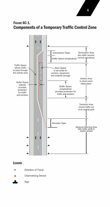
Buffer Space(longitudinal)
provides protection fortraffic and workers
Buffer Space(lateral)provides
protectionfor traffic
and workers
Buffer Space (longitudinal)
Shoulder Taper
LegendDirection of travel
Termination Arealets traffic resumenormal operations
Activity Areais where worktakes place
Transition Areamoves traffic outof its normal path
Advance Warning Areatells traffic what to
expect ahead
Work Spaceis set aside for
workers, equipment,and material storage
Downstream Taper
Traffic Spaceallows traffic
to pass throughthe activity area
FIGURE 6C-1. Components of a Temporary Traffic Control Zone
LEGEND
Direction of Travel
Sign
Channelizing Device
5
DefinitionsRural HighwayA type of roadway normally characterized by lower volumes, higher speeds, fewer turning confl icts, and less confl icts with pedestrians.
Urban StreetA type of roadway normally characterized by relatively low speeds, wide ranges of traffi c volumes, narrower lanes, frequent intersections and driveways, signifi cant pedestrian traffi c, and more businesses and houses.
Other TermsSome terms used commonly in discussing temporary traffi c control applications are not specifi cally defi ned in Part 6 of the IMUTCD. Therefore, as part of the traffi c control planning process, each agency should review Part 6 (and other appropriate sources, if needed) to determine generally how it will defi ne the terms “low speed”, “high speed”, “low volume”, and “high volume” for streets and highways under its jurisdiction.
For example, page 17 of this handbook includes the IMUTCD table “Suggested Advance Warning Sign Spacing”, which indicates that the speed category (Urban low speed or high speed) is to be determined by the highway agency.
The term “low volume road(s)” is used in the typical applications on pages 27, 29 and 34 of this handbook. Since Part 6 of the IMUTCD does not provide a specifi c defi nition of the term, each agency is responsible for addressing how these applications are used, if at all, on its system of streets and highways.
6
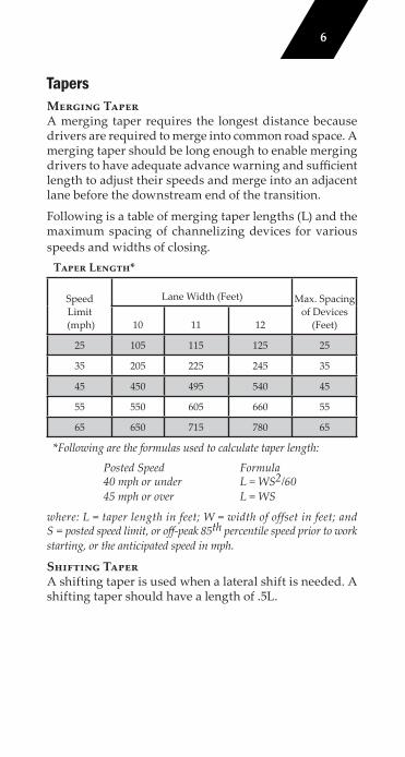
TapersMerging TaperA merging taper requires the longest distance because drivers are required to merge into common road space. A merging taper should be long enough to enable merging drivers to have adequate advance warning and suffi cient length to adjust their speeds and merge into an adjacent lane before the downstream end of the transition.
Following is a table of merging taper lengths (L) and the maximum spacing of channelizing devices for various speeds and widths of closing.
Taper Length*
Speed Limit
(mph)
Lane Width (Feet) Max. Spacing of Devices
(Feet)10 11 12
25 105 115 125 25
35 205 225 245 35
45 450 495 540 45
55 550 605 660 55
65 650 715 780 65
*Following are the formulas used to calculate taper length:
Posted Speed Formula 40 mph or under L = WS2/60 45 mph or over L = WS
where: L = taper length in feet; W = width of offset in feet; and S = posted speed limit, or off -peak 85th percentile speed prior to work starting, or the anticipated speed in mph.
Shifting TaperA shifting taper is used when a lateral shift is needed. A shifting taper should have a length of .5L.
7
Shoulder TaperA shoulder taper may be beneficial on a high-speed roadway where shoulders are part of the activity area and are closed, or when improved shoulders might be mistaken as a driving lane. Shoulder tapers should have a length of at least 0.33 L.
Downstream TaperA downstream taper should have a minimum length of 50 feet and a maximum length of 100 feet with devices placed at a spacing of approximately 20 feet.
One-Lane, Two-Way TaperA one-lane, two-way taper is used in advance of an activity area that occupies part of a two-way roadway in such a way that a portion of the road is used alternately by traffi c in each direction. A one-lane, two-way taper should have a minimum length of 50 feet and a maximum length of 100 feet with channelizing devices at approximately 20-foot spacings.
FlaggingFlaggersA fl agger shall be a person who provides temporary traffi c control. A fl agger should be able to demonstrate the following abilities:
1. Ability to receive and communicate specifi c instructions.2. Ability to move and maneuver quickly.3. Ability to control signaling devices.4. Ability to understand and apply safe traffi c control
practices.5. Ability to recognize dangerous situations and warn
coworkers.
8
Flagger UseWhen a one-lane, two-way temporary traffi c control zone is short enough to allow a fl agger to see from one end of the zone to the other, traffi c may be controlled by either a single fl agger or by a fl agger at each end of the section.
When a single flagger is used, the flagger should be stationed on the shoulder opposite the constriction or work space, or in a position where good visibility and traffi c control can be maintained at all times.
High Visibility ClothingFor daytime and nightt ime activity, fl aggers shall wear high-visibility safety apparel that meets the Performance Class 2 or 3 requirements of the ANSI/ISEA 107-2004 publication entitled “American National Standard for High-Visibility Apparel and Headwear” and labeled as meeting the ANSI 107-2004 standard performance for Class 2 or 3 risk exposure. The apparel background (outer) material color shall be fl uorescent orange-red, fl uorescent yellow-green, or a combination of the two as defi ned in the ANSI standard. The retrorefl ective material shall be orange, yellow, white, silver, yellow-green, or a fl uorescent version of these colors, and shall be visible at a minimum distance of 1000 feet. The retrorefl ective safety apparel shall be designed to clearly identify the wearer as a person.
Hand-Signaling DevicesThe sign paddle bearing the message STOP or SLOW provides road users with more positive guidance than fl ags and should be the primary hand-signaling device.
The STOP/SLOW paddle shall have an octagonal shape on a rigid handle. STOP/SLOW paddles shall be at least 18 inches wide with lett ers at least 6 inches high. The STOP face shall have white lett ers and a white border on a red background. The SLOW face shall have black lett ers and a black border on an orange background. When used at night, the STOP/SLOW paddle shall be retrorefl ectorized.
9
Flags, when used, shall be a minimum of 24 inches square, made of a good grade of red material, and securely fastened to a staff that is approximately 36 inches in length. The free edge of a fl ag should be weighted so the fl ag will hang vertically, even in heavy winds. When used at nightt ime, fl ags shall be retrorefl ectorized red.
Flagger StationsFlagger stations shall be located such that approaching road users will have suffi cient distance to stop at an intended stopping point.
Guidelines for determining the distance of the fl agger station in advance of the work space are shown in the table on page 17. The distances shown may be increased for downgrades and other conditions that aff ect stopping distance.
Except in emergency situations, fl agger stations shall be preceded by an advance warning sign or signs. Except in emergency situations, fl agger stations shall be illuminated at night.
The fl agger should stand either on the shoulder adjacent to the road user being controlled or in the closed lane prior to stopping road users. A fl agger should only stand in the lane being used by moving road users after road users have stopped. The fl agger should be clearly visible to the fi rst approaching road user at all times. The fl agger also should be visible to other road users. The fl agger should be stationed suffi ciently in advance of the workers to warn them (for example, with audible warning devices such as horns or whistles) of approaching danger by out-of-control vehicles. The fl agger should stand alone, away from other workers, work vehicles, or equipment.
At spot lane closures where adequate sight distance is available for the reasonably safe handling of traffi c, the use of one fl agger may be suffi cient. The table on page 17 may be used to determine the visibility distance for road users approaching the fl agger.
10
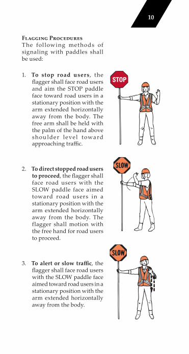
Flagging ProceduresThe fol lowing methods of signaling with paddles shall be used:
1. To stop road users , the fl agger shall face road users and aim the STOP paddle face toward road users in a stationary position with the arm extended horizontally away from the body. The free arm shall be held with the palm of the hand above shou lder level towa rd approaching traffi c.
2. To direct stopped road users to proceed, the fl agger shall face road users with the SLOW paddle face aimed toward road users in a stationary position with the arm extended horizontally away from the body. The flagger shall motion with the free hand for road users to proceed.
3. To alert or slow traffi c, the fl agger shall face road users with the SLOW paddle face aimed toward road users in a stationary position with the arm extended horizontally away from the body.
11
CommunicationWhen two flaggers are used, they can communicate verbally or visually if they are close enough and visible to each other. One of the fl aggers should be designated as the coordinator. Where the end of a one-lane section is not visible from the other end, the fl aggers may maintain control using such methods as:
1. Radio or fi eld telephone,
2. Flag transfer method where the driver of the last vehicle proceeding into the one-lane section is given a red fl ag (or other token) and instructed to deliver it to the fl agger at the other end,
3. An official car that follows the last road user proceeding through the section, or
4. A pilot car to guide a queue of vehicles through the temporary traffi c control zone or detour. The fl ag transfer or offi cial car method should only be used for a maximum length of about one mile. The pilot car shall have a sign mounted on the rear of the vehicle.
Arrow BoardsAn arrow board shall be a sign with a matrix of elements capable of either fl ashing or sequential displays. This sign shall provide additional warning and directional information to assist in merging and controlling road users through or around a temporary traffi c control zone. The minimum size shall be 48” x 24” with at least 12 panel lamps to provide a minimum legibility distance of 1/2 mile. Arrow board elements shall be capable of at least a 50 percent dimming from full brilliance. The dimmed mode shall be used for nightt ime operation of arrow boards.
An arrow board should be used in combination with appropriate signs, channelizing devices, or other temporary traffi c control devices. An arrow board should be placed on the shoulder of the roadway or, if practical, further from the traveled lane. It should be delineated with retrorefl ective temporary traffi c control devices. When
12
an arrow board is not being used, it should be removed; if not removed, it should be shielded; or if the previous two options are not feasible, it should be delineated with retrorefl ective temporary traffi c control devices.
NOTE: Review and understand the full text of Section 6F.61 of the IMUTCD prior to implementing a traffi c plan using Arrow Boards.
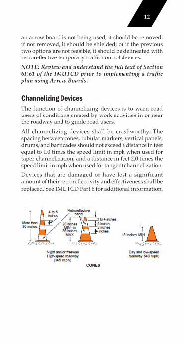
Channelizing DevicesThe function of channelizing devices is to warn road users of conditions created by work activities in or near the roadway and to guide road users.
All channelizing devices shall be crashworthy. The spacing between cones, tubular markers, vertical panels, drums, and barricades should not exceed a distance in feet equal to 1.0 times the speed limit in mph when used for taper channelization, and a distance in feet 2.0 times the speed limit in mph when used for tangent channelization.
Devices that are damaged or have lost a significant amount of their retrorefl ectivity and eff ectiveness shall be replaced. See IMUTCD Part 6 for additional information.
13
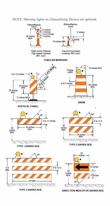
NOTE: Warning lights on Channelizing Devices are optional.
14
Warning LightsWarning lights shall be in accordance with the current ITE “Purchase Specifi cation for Flashing and Steady-Burn Warning Lights.” When warning lights are used, they shall be mounted on signs or channelizing devices in a manner that, if hit by an errant vehicle, they will not be likely to penetrate the windshield.
Type A Low-Intensity fl ashing warning lights are used to warn road users during nightt ime hours that they are approaching or proceeding in a potentially hazardous area. Type A warning lights may be mounted on channelizing devices.
Type B High-Intensity fl ashing warning lights are used to warn road users during both daylight and nightt ime hours that they are approaching a potentially hazardous area. Type B warning lights are designed to operate 24 hours per day and may be mounted on advance warning signs or on independent supports.
Type C Steady-Burn warning lights and Type D 360-degree Steady-Burn warning lights may be used during nighttime hours to delineate the edge of the traveled way. When used to delineate a curve, Type C and Type D 360-degree warning lights should only be used on devices on the outside of the curve, and not on the inside of the curve.
Nighttime OperationsAll traffi c control devices shall be retrorefl ectorized when used at night. Workers shall wear retrorefl ectorized vests. Cones shall be equipped with a refl ective collar when used at night. When barricades are used, it is desirable to add fl ashing lights when the barricades are used singly and steady burn lights when they are used in a series for channelization. If a fl agger is used, the fl agger stations should be adequately illuminated.
15
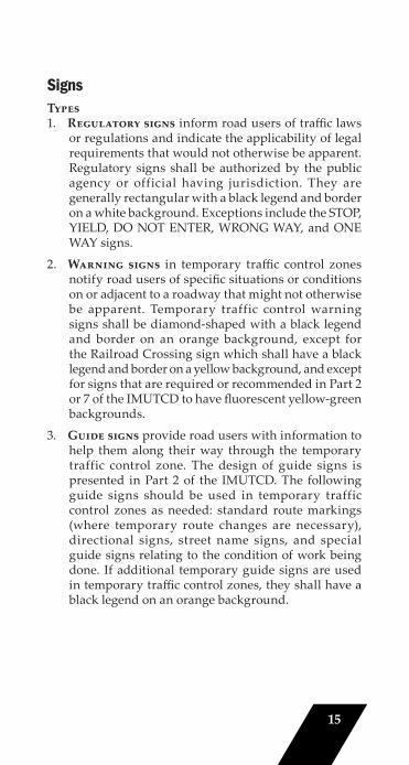
SignsTypes1. Regulatory signs inform road users of traffi c laws
or regulations and indicate the applicability of legal requirements that would not otherwise be apparent. Regulatory signs shall be authorized by the public agency or official having jurisdiction. They are generally rectangular with a black legend and border on a white background. Exceptions include the STOP, YIELD, DO NOT ENTER, WRONG WAY, and ONE WAY signs.
2. Warning signs in temporary traffi c control zones notify road users of specifi c situations or conditions on or adjacent to a roadway that might not otherwise be apparent. Temporary traffic control warning signs shall be diamond-shaped with a black legend and border on an orange background, except for the Railroad Crossing sign which shall have a black legend and border on a yellow background, and except for signs that are required or recommended in Part 2 or 7 of the IMUTCD to have fl uorescent yellow-green backgrounds.
3. Guide signs provide road users with information to help them along their way through the temporary traffic control zone. The design of guide signs is presented in Part 2 of the IMUTCD. The following guide signs should be used in temporary traffic control zones as needed: standard route markings (where temporary route changes are necessary), directional signs, street name signs, and special guide signs relating to the condition of work being done. If additional temporary guide signs are used in temporary traffi c control zones, they shall have a black legend on an orange background.
16
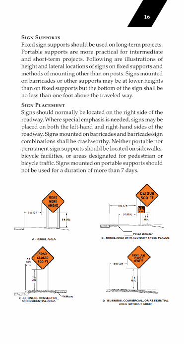
Sign SupportsFixed sign supports should be used on long-term projects. Portable supports are more practical for intermediate and short-term projects. Following are illustrations of height and lateral locations of signs on fi xed supports and methods of mounting other than on posts. Signs mounted on barricades or other supports may be at lower heights than on fi xed supports but the bott om of the sign shall be no less than one foot above the traveled way.
Sign PlacementSigns should normally be located on the right side of the roadway. Where special emphasis is needed, signs may be placed on both the left-hand and right-hand sides of the roadway. Signs mounted on barricades and barricade/sign combinations shall be crashworthy. Neither portable nor permanent sign supports should be located on sidewalks, bicycle facilities, or areas designated for pedestrian or bicycle traffi c. Signs mounted on portable supports should not be used for a duration of more than 7 days.
17
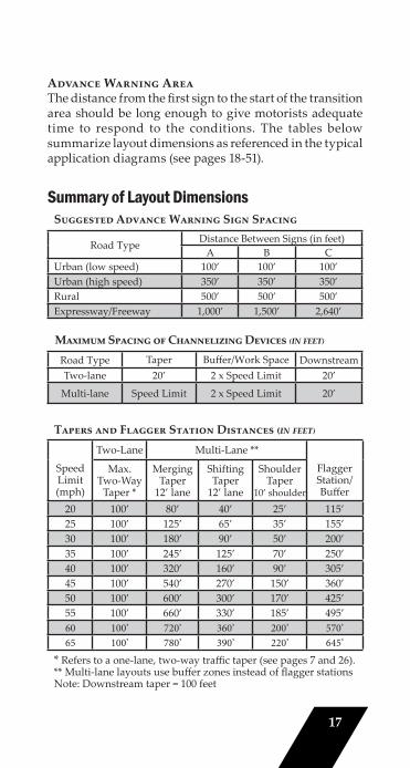
Advance Warning AreaThe distance from the fi rst sign to the start of the transition area should be long enough to give motorists adequate time to respond to the conditions. The tables below summarize layout dimensions as referenced in the typical application diagrams (see pages 18-51).
Summary of Layout DimensionsSuggested Advance Warning Sign Spacing
Road Type Distance Between Signs (in feet)A B C
Urban (low speed) 100’ 100’ 100’Urban (high speed) 350’ 350’ 350’Rural 500’ 500’ 500’Expressway/Freeway 1,000’ 1,500’ 2,640’
Maximum Spacing of Channelizing Devices ₍in feet₎Road Type Taper Buff er/Work Space DownstreamTwo-lane 20’ 2 x Speed Limit 20’
Multi-lane Speed Limit 2 x Speed Limit 20’
Tapers and Flagger Station Distances ₍in feet₎
Speed Limit (mph)
Two-Lane Multi-Lane **
Flagger Station/ Buff er
Max.Two-Way
Taper *
Merging Taper
12’ lane
Shifting Taper
12’ lane
Shoulder Taper
10’ shoulder
20 100’ 80’ 40’ 25’ 115’25 100’ 125’ 65’ 35’ 155’30 100’ 180’ 90’ 50’ 200’35 100’ 245’ 125’ 70’ 250’40 100’ 320’ 160’ 90’ 305’45 100’ 540’ 270’ 150’ 360’50 100’ 600’ 300’ 170’ 425’55 100’ 660’ 330’ 185’ 495’60 100’ 720’ 360’ 200’ 570’65 100’ 780’ 390’ 220’ 645’
* Refers to a one-lane, two-way traffi c taper (see pages 7 and 26).** Multi-lane layouts use buff er zones instead of fl agger stationsNote: Downstream taper = 100 feet
18
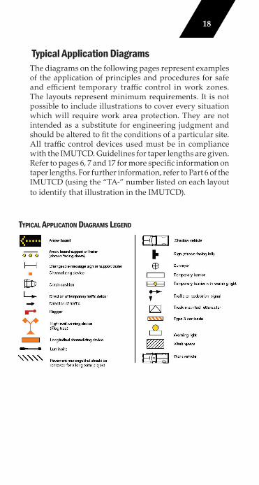
Typical Application DiagramsThe diagrams on the following pages represent examples of the application of principles and procedures for safe and effi cient temporary traffi c control in work zones. The layouts represent minimum requirements. It is not possible to include illustrations to cover every situation which will require work area protection. They are not intended as a substitute for engineering judgment and should be altered to fi t the conditions of a particular site. All traffi c control devices used must be in compliance with the IMUTCD. Guidelines for taper lengths are given. Refer to pages 6, 7 and 17 for more specifi c information on taper lengths. For further information, refer to Part 6 of the IMUTCD (using the “TA-” number listed on each layout to identify that illustration in the IMUTCD).
TYPICAL APPLICATION DIAGRAMS LEGEND
19
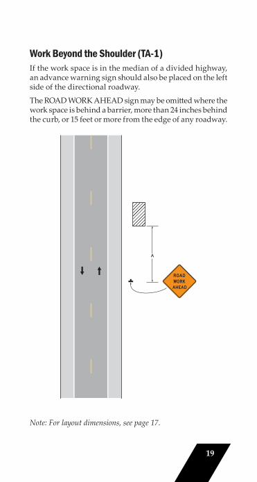
Work Beyond the Shoulder (TA-1)If the work space is in the median of a divided highway, an advance warning sign should also be placed on the left side of the directional roadway.
The ROAD WORK AHEAD sign may be omitt ed where the work space is behind a barrier, more than 24 inches behind the curb, or 15 feet or more from the edge of any roadway.
Note: See Tables 6H-2 and 6H-3 for the of the symbols and/or letter codes this figure.
Note: For layout dimensions, see page 17.
20
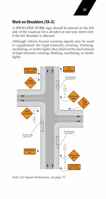
Work on Shoulders (TA-3)A SHOULDER WORK sign should be placed on the left side of the roadway for a divided or one-way street only if the left shoulder is aff ected.
Although vehicle hazard warning signals may be used to supplement the high-intensity rotating, flashing, oscillating, or strobe lights, they shall not be used instead of high-intensity rotating, fl ashing, oscillating, or strobe lights.
Shoulder taper(see Note 7)
ee Tables 6H-2 and 6H-3r the meaning of thembols and/or letter
odes used in this figure.
1/3 L
A
Shoulder taper(see Note 7)
1/3 L
A
B
Shoulder taper(see Note 7)
1/3 L
A
Note: For layout dimensions, see page 17.
21
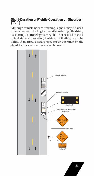
Short-Duration or Mobile Operation on Shoulder (TA-4)Although vehicle hazard warning signals may be used to supplement the high-intensity rotating, flashing, oscillating, or strobe lights, they shall not be used instead of high-intensity rotating, fl ashing, oscillating, or strobe lights. If an arrow board is used for an operation on the shoulder, the caution mode shall be used.
Note: See Tables 6H-2 and 6H-3 for the meaning of the symbols and/or letter codes used in this figure.
(optional)
(optional)
See Note 1
Shadow vehicle
Work vehicle
Truck-mounted attenuator(optional)
22
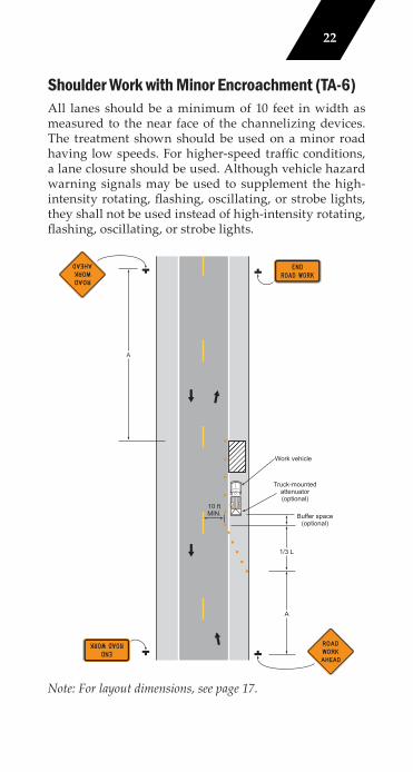
Shoulder Work with Minor Encroachment (TA-6)All lanes should be a minimum of 10 feet in width as measured to the near face of the channelizing devices. The treatment shown should be used on a minor road having low speeds. For higher-speed traffi c conditions, a lane closure should be used. Although vehicle hazard warning signals may be used to supplement the high-intensity rotating, fl ashing, oscillating, or strobe lights, they shall not be used instead of high-intensity rotating, fl ashing, oscillating, or strobe lights.
Buffer space(optional)
Note: See Tables 6H-2 and 6H-3 for the meaning of the symbols and/or letter codes used in this figure.
Typical Application 6
Truck-mountedattenuator(optional)
A
A
1/3 L
Work vehicle
10 ftMIN.
Note: For layout dimensions, see page 17.
23
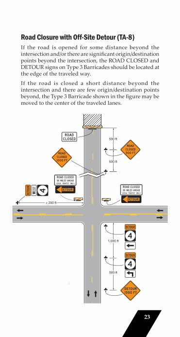
Road Closure with Off-Site Detour (TA-8)If the road is opened for some distance beyond the intersection and/or there are signifi cant origin/destination points beyond the intersection, the ROAD CLOSED and DETOUR signs on Type 3 Barricades should be located at the edge of the traveled way.
If the road is closed a short distance beyond the intersection and there are few origin/destination points beyond, the Type 3 Barricade shown in the fi gure may be moved to the center of the traveled lanes.
Note: See Tables 6H-2 and 6H-3 for the meaning of the symbols and/or letter codes used in this figure. See Section 2D.11 and Figure 2D-3 for the correct design of an Ohio State Route sign.
500 ft
1,000 ft
500 ft
500 ft
200 ft
24
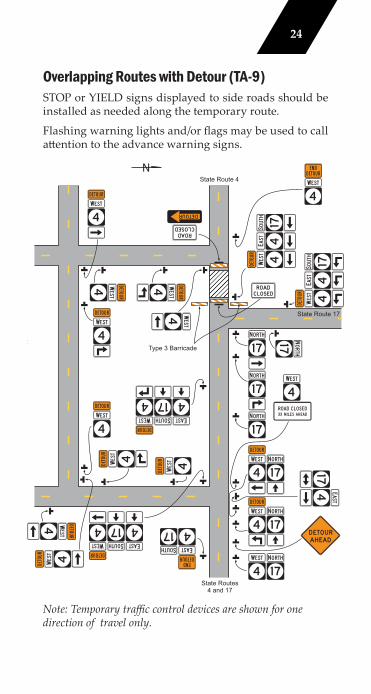
Overlapping Routes with Detour (TA-9)STOP or YIELD signs displayed to side roads should be installed as needed along the temporary route.
Flashing warning lights and/or fl ags may be used to call att ention to the advance warning signs.
Note: Temporary traffi c control devices are shown for one direction of travel only.
H-3 for mbols
d in this .D.11 and rect e Route
State Route 4
State Routes4 and 17
State Route 17
Type 3 Barricade
t
25
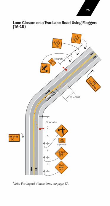
Lane Closure on a Two-Lane Road Using Flaggers (TA-10)For low-volume situations with short work zones on straight roadways where the fl agger is visible to road users approaching from both directions, a single fl agger, positioned to be visible to road users approaching from both directions, may be used.
The ROAD WORK AHEAD and the END ROAD WORK signs may be omitt ed for short-duration operations.
Flashing warning lights and/or fl ags may be used to call att ention to the advance warning signs. A BE PREPARED TO STOP sign may be added to the sign series.
The buff er space should be extended so that the two-way traffi c taper is placed before a horizontal (or crest vertical) curve to provide adequate sight distance for the fl agger and a queue of stopped vehicles. At night, fl agger stations shall be illuminated, except in emergencies. When used, the BE PREPARED TO STOP sign should be located between the Flagger sign and the ONE LANE ROAD sign.
When a grade crossing exists within or upstream of the transition area and it is anticipated that queues resulting from the lane closure might extend through the grade crossing, the temporary traffi c control zone should be extended so that the transition area precedes the grade crossing.
When a grade crossing equipped with active warning devices exists within the activity area, provisions should be made for keeping fl aggers informed as to the activation status of these warning devices.
When a grade crossing exists within the activity area, drivers operating on the left-hand side of the normal center line should be provided with comparable warning devices as for drivers operating on the right-hand side of the normal center line.
Early coordination with the railroad company or light rail transit agency should occur before work starts.
(See IIlustration on Next Page)
26
Lane Closure on a Two-Lane Road Using Flaggers (TA-10)
Note: For layout dimensions, see page 17.
te: See Tables 6H-2 and 6H-3for the meaning of thesymbols and/or lettercodes used in this figure.
50 to 100 ft
(optional)A
B
C
(optional)
50 to 100 ft
A
B
C
27
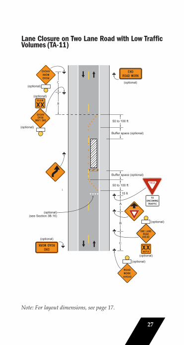
Lane Closure on Two Lane Road with Low Traffic Volumes (TA-11)
Note: For layout dimensions, see page 17.
(optional)(see Section 3B.16)
Note: See Tables 6H-2 and 6H-3for the meaning of thesymbols and/or lettercodes used in this figure.
A
B
C
(optional)
(optional)
(optional)
15 ft
Buffer space (optional)
(optional)
(optional)
(optional)
(optional)
B
C (optional)
50 to 100 ft
50 to 100 ft
Buffer space (optional)
28
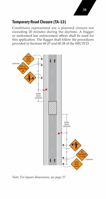
Temporary Road Closure (TA-13)Conditions represented are a planned closure not exceeding 20 minutes during the daytime. A flagger or uniformed law enforcement offi cer shall be used for this application. The fl agger shall follow the procedures provided in Sections 6E.07 and 6E.08 of the IMUTCD.
Note: See Tables 6H-2 and 6H-3 for the meaning of the symbols and/or letter codes used in this figure.
A
B
C
A
B
C
Typical Application 13
(optional)
Bufferspace
(optional)
(optional)
Bufferspace
(optional)
Note: For layout dimensions, see page 17.
29
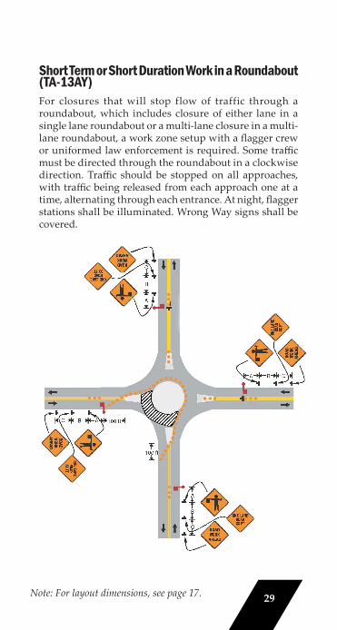
Short Term or Short Duration Work in a Roundabout (TA-13AY) For closures that will stop flow of traffic through a roundabout, which includes closure of either lane in a single lane roundabout or a multi-lane closure in a multi-lane roundabout, a work zone setup with a fl agger crew or uniformed law enforcement is required. Some traffi c must be directed through the roundabout in a clockwise direction. Traffi c should be stopped on all approaches, with traffi c being released from each approach one at a time, alternating through each entrance. At night, fl agger stations shall be illuminated. Wrong Way signs shall be covered.
Note: For layout dimensions, see page 17. 29
30
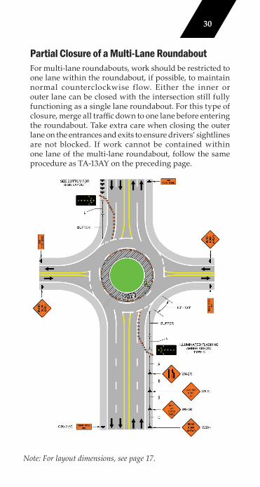
Partial Closure of a Multi-Lane RoundaboutFor multi-lane roundabouts, work should be restricted to one lane within the roundabout, if possible, to maintain normal counterclockwise flow. Either the inner or outer lane can be closed with the intersection still fully functioning as a single lane roundabout. For this type of closure, merge all traffi c down to one lane before entering the roundabout. Take extra care when closing the outer lane on the entrances and exits to ensure drivers’ sightlines are not blocked. If work cannot be contained within one lane of the multi-lane roundabout, follow the same procedure as TA-13AY on the preceding page.
Note: For layout dimensions, see page 17.
31
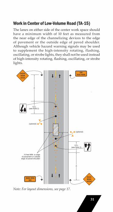
Work in Center of Low-Volume Road (TA-15)The lanes on either side of the center work space should have a minimum width of 10 feet as measured from the near edge of the channelizing devices to the edge of pavement or the outside edge of paved shoulder. Although vehicle hazard warning signals may be used to supplement the high-intensity rotating, flashing, oscillating, or strobe lights, they shall not be used instead of high-intensity rotating, fl ashing, oscillating, or strobe lights.
Note: For layout dimensions, see page 17.
(optional)
(optional)
10 feet MIN. to edgeof pavement or outside
edge of paved shoulder
1/2 L
Note: See Tables 6H-2 and 6H-3 for the meaning of the symbols and/or letter codes used in this figure.
A
1/2 L
A
(see Note 2)
(see Note 2)
32
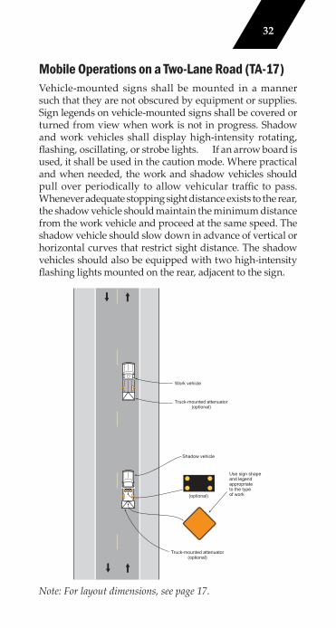
Mobile Operations on a Two-Lane Road (TA-17)Vehicle-mounted signs shall be mounted in a manner such that they are not obscured by equipment or supplies. Sign legends on vehicle-mounted signs shall be covered or turned from view when work is not in progress. Shadow and work vehicles shall display high-intensity rotating, fl ashing, oscillating, or strobe lights. If an arrow board is used, it shall be used in the caution mode. Where practical and when needed, the work and shadow vehicles should pull over periodically to allow vehicular traffi c to pass.Whenever adequate stopping sight distance exists to the rear, the shadow vehicle should maintain the minimum distance from the work vehicle and proceed at the same speed. The shadow vehicle should slow down in advance of vertical or horizontal curves that restrict sight distance. The shadow vehicles should also be equipped with two high-intensity fl ashing lights mounted on the rear, adjacent to the sign.
Truck-mounted attenuator(optional)
Work vehicle
Shadow vehicle
Use sign shapeand legendappropriateto the typeof work
Truck-mounted attenuator(optional)
Note: See Tables 6H-2 and 6H-3 for the meaning of the symbols and/or letter codes used in this figure.
(optional)
Note: For layout dimensions, see page 17.
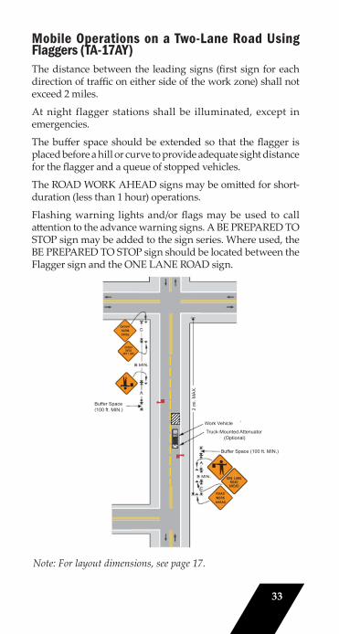
Mobile Operations on a Two-Lane Road Using Flaggers (TA-17AY)The distance between the leading signs (fi rst sign for each direction of traffi c on either side of the work zone) shall not exceed 2 miles.
At night flagger stations shall be illuminated, except in emergencies.
The buff er space should be extended so that the fl agger is placed before a hill or curve to provide adequate sight distance for the fl agger and a queue of stopped vehicles.
The ROAD WORK AHEAD signs may be omitt ed for short-duration (less than 1 hour) operations.
Flashing warning lights and/or fl ags may be used to call att ention to the advance warning signs. A BE PREPARED TO STOP sign may be added to the sign series. Where used, the BE PREPARED TO STOP sign should be located between the Flagger sign and the ONE LANE ROAD sign.
Note: For layout dimensions, see page 17.
33
Buffer Space(100 ft. MIN.)
Work Vehicle
2 m
i. M
AX
.
Truck-Mounted Attenuator(Optional)
Buffer Space (100 ft. MIN.)
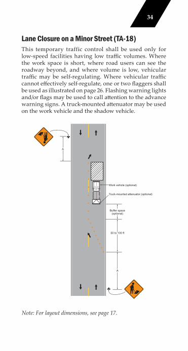
Lane Closure on a Minor Street (TA-18)This temporary traffic control shall be used only for low-speed facilities having low traffi c volumes. Where the work space is short, where road users can see the roadway beyond, and where volume is low, vehicular traffi c may be self-regulating. Where vehicular traffi c cannot eff ectively self-regulate, one or two fl aggers shall be used as illustrated on page 26. Flashing warning lights and/or fl ags may be used to call att ention to the advance warning signs. A truck-mounted att enuator may be used on the work vehicle and the shadow vehicle.
Note: For layout dimensions, see page 17.
Note: See Tables 6H-2 and 6H-3 for the meaning of the symbols and/or letter codes used in this figure.
Work vehicle (optional)
Truck-mounted attenuator (optional)
Buffer space(optional)
50 to 100 ft
A
A
34
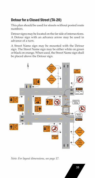
Detour for a Closed Street (TA-20)This plan should be used for streets without posted route numbers.
Detour signs may be located on the far side of intersections. A Detour sign with an advance arrow may be used in advance of a turn.
A Street Name sign may be mounted with the Detour sign. The Street Name sign may be either white on green or black on orange. When used, the Street Name sign shall be placed above the Detour sign.
Note: For layout dimensions, see page 17.
Note: See Tables 6H-2 and 6H-3 for the meaning of the symbols and/or letter codes used in this figure.
A
B
A
B
35
36
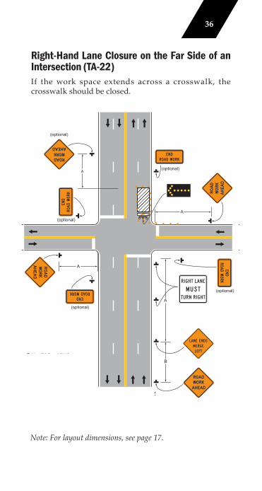
Right-Hand Lane Closure on the Far Side of an Intersection (TA-22)If the work space extends across a crosswalk, the crosswalk should be closed.
Note: For layout dimensions, see page 17.
Typical Application 22
e Tables 6H-2 and 6H-3the meaning of the
mbols and/or letterdes used in this figure.
(optional)
(optional)
(optional)
(optional)
(optional)
A
A
B
A
A
36
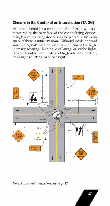
Closure in the Center of an Intersection (TA-26)All lanes should be a minimum of 10 feet in width as measured to the near face of the channelizing devices. A high-level warning device may be placed in the work space, if there is suffi cient room. Although vehicle hazard warning signals may be used to supplement the high-intensity rotating, fl ashing, oscillating, or strobe lights, they shall not be used instead of high-intensity rotating, fl ashing, oscillating, or strobe lights.
Note: For layout dimensions, see page 17.
(optional)
ote: See Tables 6H-2 and 6H-3for the meaning of the symbols and/or letter codesused in this figure.
1/2 L*
A
10 ftMIN.
1/2 L* A
10 ft MIN.
1/2 L*
A
1/2 L*A
10 ft MIN.
10 ftMIN.
37
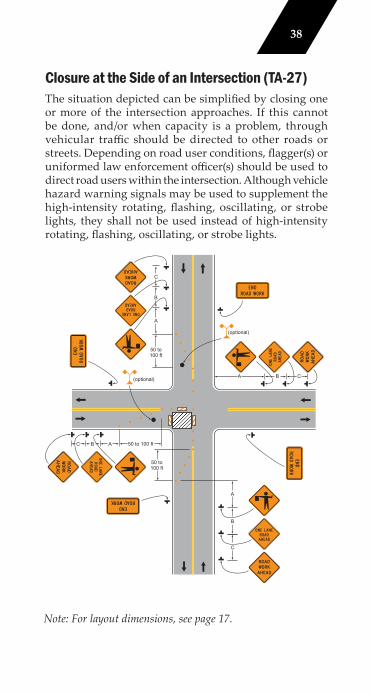
Closure at the Side of an Intersection (TA-27)The situation depicted can be simplifi ed by closing one or more of the intersection approaches. If this cannot be done, and/or when capacity is a problem, through vehicular traffi c should be directed to other roads or streets. Depending on road user conditions, fl agger(s) or uniformed law enforcement offi cer(s) should be used to direct road users within the intersection. Although vehicle hazard warning signals may be used to supplement the high-intensity rotating, fl ashing, oscillating, or strobe lights, they shall not be used instead of high-intensity rotating, fl ashing, oscillating, or strobe lights.
Note: For layout dimensions, see page 17.
See Note 2 for flagger information
Note: See Tables 6H-2 and 6H-3 for the meaning of the symbols and/or letter codes used in this figure.
Typical Application 27
A 50 to 100 ftBC
50 to100 ft
50 to100 ft
A
B
C
A
B
C
(optional) A B C
(optional)
38
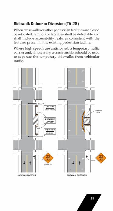
Sidewalk Detour or Diversion (TA-28)When crosswalks or other pedestrian facilities are closed or relocated, temporary facilities shall be detectable and shall include accessibility features consistent with the features present in the existing pedestrian facility.
Where high speeds are anticipated, a temporary traffi c barrier and, if necessary, a crash cushion should be used to separate the temporary sidewalks from vehicular traffi c.
36 inchesMIN.
(optional)
SIDEWALK DETOUR SIDEWALK DIVERSION
39
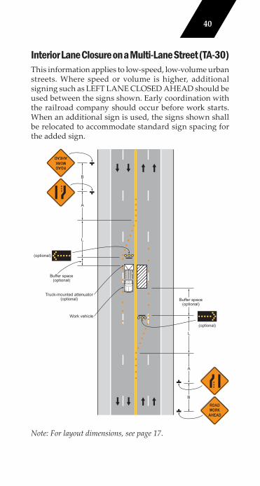
Interior Lane Closure on a Multi-Lane Street (TA-30)This information applies to low-speed, low-volume urban streets. Where speed or volume is higher, additional signing such as LEFT LANE CLOSED AHEAD should be used between the signs shown. Early coordination with the railroad company should occur before work starts. When an additional sign is used, the signs shown shall be relocated to accommodate standard sign spacing for the added sign.
Note: For layout dimensions, see page 17.
See Tables 6H-2 and 6H-3for the meaning of thesymbols and/or lettercodes used in this figure.
Typical Application 30
(optional)
Buffer space(optional)
Truck-mounted attenuator(optional)
Work vehicle
(optional)
Buffer space(optional)
L
A
B
L
A
B
40
Stationary Lane Closure on a Divided Highway (Short Term) (TA-33)This information also shall be used when work is being performed in the lane adjacent to the median on a divided highway. In this case, the LEFT LANE CLOSED signs and the corresponding Lane Ends signs shall be substituted. When a side road intersects the highway within the temporary traffi c control zone, additional temporary traffi c control devices shall be placed as needed.
A truck-mounted att enuator may be used on the work vehicle and/or shadow vehicle. Where conditions permit, restricting all vehicles, equipment, workers, and their activities to one side of the roadway might be advantageous.
An arrow board shall be used when a freeway lane is closed. When more than one freeway lane is closed, a separate arrow board shall be used for each closed lane.
(See Illustration Below)
41
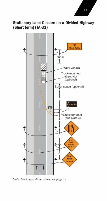
Stationary Lane Closure on a Divided Highway (Short Term) (TA-33)
Note: For layout dimensions, see page 17.Note: See Tables
Buffer space (optional)
Shoulder taper(see Note 3)A
L
B
C
500 ft
Work vehicle
Truck-mountedattenuator(optional)
42
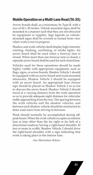
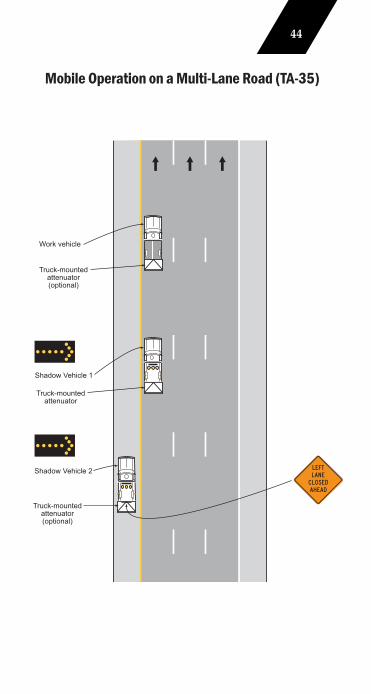
Mobile Operation on a Multi-Lane Road (TA-35)Arrow boards shall, as a minimum, be Type B, with a size of 60 x 30 inches. Vehicle-mounted signs shall be mounted in a manner such that they are not obscured by equipment or supplies. Sign legends on vehicle-mounted signs shall be covered or turned from view when work is not in progress.
Shadow and work vehicles shall display high-intensity rotating, flashing, oscillating, or strobe lights. An arrow board shall be used when a freeway lane is closed. When more than one freeway lane is closed, a separate arrow board shall be used for each closed lane.
Vehicles used for these operations should be made highly visible with appropriate equipment, such as fl ags, signs, or arrow boards. Shadow Vehicle 1 should be equipped with an arrow board and truck-mounted attenuator. Shadow Vehicle 2 should be equipped with an arrow board. An appropriate lane closure sign should be placed on Shadow Vehicle 2 so as not to obscure the arrow board. Shadow Vehicle 2 should travel at a varying distance from the work operation so as to provide adequate sight distance for vehicular traffi c approaching from the rear. The spacing between the work vehicles and the shadow vehicles, and between each shadow vehicle should be minimized to deter road users from driving in between.
Work should normally be accomplished during off -peak hours. When the work vehicle occupies an interior lane (a lane other than the far right or far left) of a directional roadway having a right-hand shoulder 10 feet or more in width, Shadow Vehicle 2 should drive the right-hand shoulder with a sign indicating that work is taking place in the interior lane.
(See Illustration Below)
43
Mobile Operation on a Multi-Lane Road (TA-35)
Note: See Tables 6H- 6H-3 for the me of the symbols letter codes use
this figure
Work vehicle
Truck-mountedattenuator(optional)
Truck-mountedattenuator
Truck-mountedattenuator(optional)
Shadow Vehicle 1
Shadow Vehicle 2
44
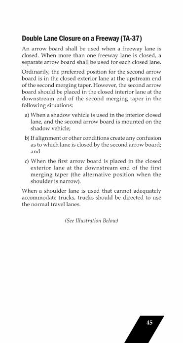
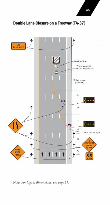
Double Lane Closure on a Freeway (TA-37)An arrow board shall be used when a freeway lane is closed. When more than one freeway lane is closed, a separate arrow board shall be used for each closed lane.
Ordinarily, the preferred position for the second arrow board is in the closed exterior lane at the upstream end of the second merging taper. However, the second arrow board should be placed in the closed interior lane at the downstream end of the second merging taper in the following situations:
a) When a shadow vehicle is used in the interior closed lane, and the second arrow board is mounted on the shadow vehicle;
b) If alignment or other conditions create any confusion as to which lane is closed by the second arrow board; and
c) When the fi rst arrow board is placed in the closed exterior lane at the downstream end of the first merging taper (the alternative position when the shoulder is narrow).
When a shoulder lane is used that cannot adequately accommodate trucks, trucks should be directed to use the normal travel lanes.
(See Illustration Below)
45
Double Lane Closure on a Freeway (TA-37)
Note: For layout dimensions, see page 17.
Shoulder taper
Note: See T 6H-3 of the letter this fi
Truck-mountedattenuator (optional)
Work vehicle
Buffer space(optional)
L
2L
L
A
B
C
46
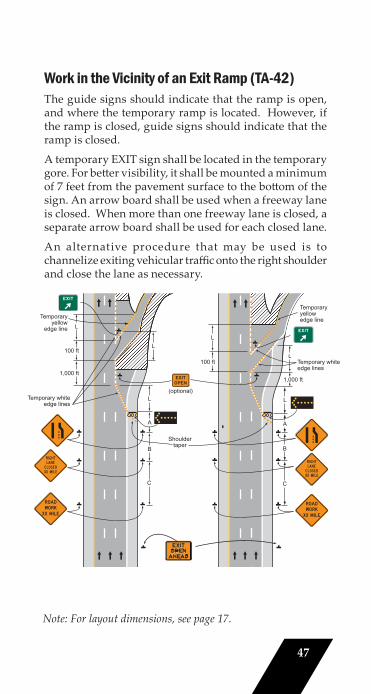
Work in the Vicinity of an Exit Ramp (TA-42)The guide signs should indicate that the ramp is open, and where the temporary ramp is located. However, if the ramp is closed, guide signs should indicate that the ramp is closed.
A temporary EXIT sign shall be located in the temporary gore. For bett er visibility, it shall be mounted a minimum of 7 feet from the pavement surface to the bott om of the sign. An arrow board shall be used when a freeway lane is closed. When more than one freeway lane is closed, a separate arrow board shall be used for each closed lane.
An alternative procedure that may be used is to channelize exiting vehicular traffi c onto the right shoulder and close the lane as necessary.
Note: For layout dimensions, see page 17.
Shouldertaper
Note: See Tables 6 6H-3 for the m of the symbo letter codes u this figure.
Temporary whiteedge lines
100 ft
1,000 ft
Temporaryyellow
edge line L
100 ft
(optional)L
A
B
C
L
A
B
C
1,000 ft
Temporary whiteedge lines
Temporaryyellowedge line
LL
47
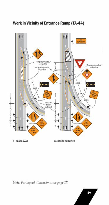
Work in the Vicinity of an Entrance Ramp (TA-44)An acceleration lane of sufficient length should be provided whenever possible as shown on the left diagram on the following page.
For the information shown on the diagram on the right side of the typical application, where inadequate acceleration distance exists for the temporary entrance, the YIELD sign shall be replaced with STOP signs (one on each side of the approach).
When used, the YIELD or STOP sign should be located so that ramp vehicular traffi c has adequate sight distance of oncoming mainline vehicular traffic to select an acceptable gap in the mainline vehicular traffi c fl ow, but should not be located so far forward that motorists will be encouraged to stop in the path of the mainline traffi c. Also, a longer acceleration lane should be provided beyond the sign to reduce the gap size needed. If insuffi cient gaps are available, consideration should be given to closing the ramp.
Where STOP signs are used, a temporary stop line should be placed across the ramp at the desired stop location.
An arrow board shall be used when a freeway lane is closed. When more than one freeway lane is closed, a separate arrow board shall be used for each closed lane.
(See Illustration on Next Page)
48
Work in Vicinity of Entrance Ramp (TA-44)
Note: For layout dimensions, see page 17.
Temporary yellow edge line Temporary yellow
edge line
Note: See Tables 6H-2 a 6H-3 for the mean of the symbols and letter codes used i this figure.
LTemporary white
edge line
Shouldertaper
(optional)A
L
B
C
A - ADDED LANE B - MERGE REQUIRED
A
L
B
C
500 ft
500 ft
500 ft
49
Work in the Vicinity of a Highway-Rail Grade Crossing (TA-46)When grade crossings exist either within or in the vicinity of roadway work activities, extra care should be taken to minimize the probability of conditions being created, by lane restrictions, fl agging, or other operations, where vehicles might be stopped within the grade crossing, considered as being 15 ft on either side of the closest and farthest rail.
If the queuing of vehicles across active rail tracks cannot be avoided, a uniformed law enforcement offi cer or fl agger shall be provided at the highway-rail grade crossing to prevent vehicles from stopping within the grade crossing (as described above), even if automatic warning devices are in place.
When used, the BE PREPARED TO STOP sign should be located before the Flagger symbol sign.
At night, fl agger stations shall be illuminated, except in emergencies.
(See Illustration on Next Page)
50
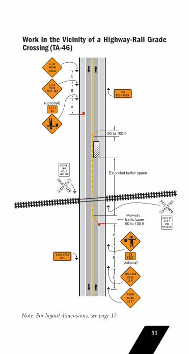
Work in the Vicinity of a Highway-Rail Grade Crossing (TA-46)
Note: For layout dimensions, see page 17.
: See Tables 6H-2 and 6H-3 for the meaning of the symbols and/or letter codes used in this figure.
(optional)
(optional)
A
B
C
50 to 100 ft
Extended buffer space
Two-waytraffic taper50 to 100 ft
A
B
C
51
Flagger’s Checklist
1. Before heading to the work zone, make sure you have all necessary equipment in working order including: warning signs, fl agging paddles, retrorefl ective clothing, and, if needed, communication equipment.
2. Place advance warning sign at the appropriate locations as shown in the table on page 17.
• Signs should always be placed in the following order from farthest from the work zone to closest: ROAD WORK AHEAD, ONE LANE ROAD AHEAD, and the fl agger symbol sign.
• Do not begin the fl agging operation until all signs are in place.
3. Always stand alone in a highly visible location when fl agging, allowing for space to stop motorists and also warn workers in case of a runaway vehicle.
4. Never stand in the path of traffi c.
• Flagger may step out near the centerline after stopping 2-3 vehicles in order to be visible to other approaching vehicles.
5. Do not leave warning signs after the fl agging operation has been terminated.
52
Supervisor’s Checklist
1. Follow Part 6 of the IMUTCD. It is Indiana’s standard for work zone traffi c control.
2. Have a plan before going to the work site.
3. Remove the devices in a timely manner.
4. Ask yourself, “What is the driver’s view of the work site – at night, during peak hours, etc.?”
5. Ask yourself, “Would I feel safe driving through this work zone?”
6. Investigate crashes/incidents to identifyif changes are needed in the traffi c control plan.
• Take photographs of all traffi c control devices.
• Sketch and dimension all devices. Indicate size of signs, placement from the edge of the travelway, and the height to the bott om of the sign.
Remember!The IMUTCD is the fi nal authority on Work Zone signage.
For questions regarding state roads, please contact your local INDOT District Offi ce.
For questions regarding local roads, please contact Indiana LTAP at 800-428-7639.
53
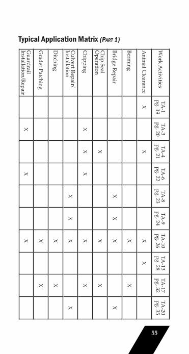
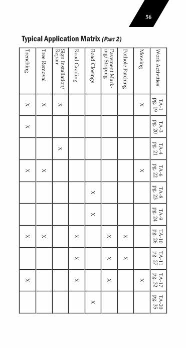
Suggested Traffic Control for Work Zone Activities
1. The matrix on pages 55-56 shows the suggested Temporary Traffic Control for various work activities.
2. A listing of common work activities is provided along with the Temporary Traffi c Control layouts (Typical Applications) that may be considered.
3. No situation will exactly match those provided in the Typical Applications. Use common sense to determine which layout best matches your situation.
4. Recommended method for using the matrix:
• Determine the work activity and fi nd it, or an activity similar to it, in the matrix.
• Determine the location of the work activity. The location of the work aff ects the type of Typical Application (TA) used.
• Determine duration of the activity. Again, the duration of work aff ects the type of TA that can be used.
• Review all suggested Typical Applications to see which best fi ts the operation.
5. Remember : The listed Temporary Traffic Controls in this booklet are merely suggestions.
54
Work A
ctivitiesTA
-1pg. 19
TA-3
pg. 20TA
-4pg. 21
TA-6
pg. 22 TA
-8pg. 23
TA-9
pg. 24TA
-10pg. 26
TA-13
pg. 28TA
-17pg. 32
TA-20
pg. 35
Anim
al Clearance
XX
XX
Berming
XX
Bridge RepairX
XX
X
Chip Seal
Operation
XX
X
Chipping
XX
XX
X
Culvert Repair/
InstallationX
XX
X
Ditching
XX
Grader Patching
XX
Guardrail
Installation/RepairX
XX
Typical Application Matrix (PART 1)
55
Work A
ctivitiesTA
-1pg. 19
TA-3
pg. 20TA
-4pg. 21
TA-6
pg. 22 TA
-8pg. 23
TA-9
pg. 24TA
-10pg. 26
TA-11
pg. 27TA
-17pg. 32
TA-20
pg. 35
Mow
ingX
XX
Pothole PatchingX
X
Pavement M
ark-ing/ Striping
XX
X
Road Closings
XX
X
Road Grading
XX
X
Sign Installation/Repair
XX
Tree Removal
XX
X
TrenchingX
XX
XX
Typical Application Matrix (PART 2)
56

Contact Information and TrainingFor further information regarding basic work zone traffic control, flagging, and other street and highway design, operation, and maintenance topics contact the Indiana LTAP Center. Indiana LTAP is a project of the Purdue University Civil Engineering Department, funded as a Local Transportation Assistance Program by the Federal Highway Administration.
Indiana LTAP Center Purdue Civil Engineering3000 Kent Avenue, Suite C2-118West Lafayette, IN 47906800.428.7639 phone (Indiana only)[email protected]/inltap
57

This page intentionally left blank

Indiana LTAP provides technical assistance and training to the highway, road and street departments of all counties, cities and towns in Indiana that are responsible for over 80,000 miles of roads and over 12,000 bridges.
Indiana LTAP works hard to serve city and town street departments, county highway departments, city and county engineering departments, city mayors and town managers, county commissioners, county surveyors, MPOs and RPOs, police departments, consultants, and contractors.
Engineering