collezione taglio collection cutting - warcom.it · according to the customer’s specific needs in...
TRANSCRIPT
COLLECTION CUTTINGCOLLEZIONE TAGLIO


01
COLLECTION CUTTINGCOLLEZIONE TAGLIO
Taglio plasma / Plasma cutting
Cesoie a ghigliottina / Guillotine shears
BIG
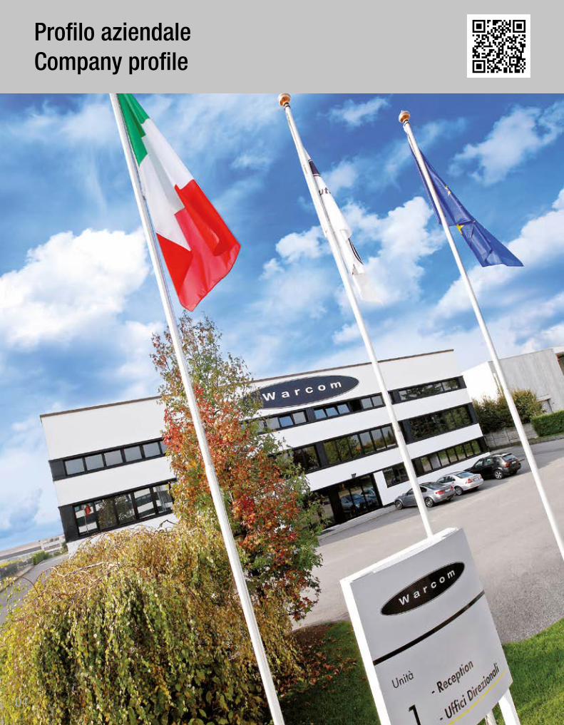
Profilo aziendale / Company profile
pag. 11
pag. 43
pag. 08
pag. 05

02
StoriaHistory Since 1959
03
04
Profilo aziendaleCompany profile
05
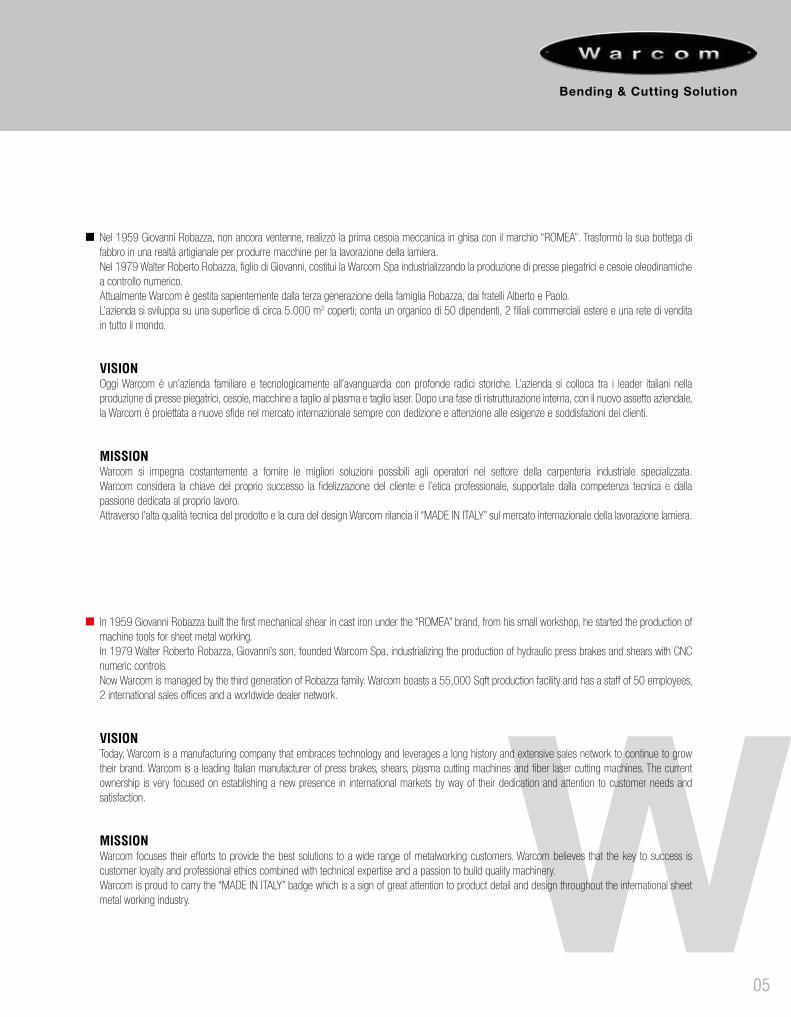
Nel 1959 Giovanni Robazza, non ancora ventenne, realizzò la prima cesoia meccanica in ghisa con il marchio “ROMEA”. Trasformò la sua bottega di fabbro in una realtà artigianale per produrre macchine per la lavorazione della lamiera. Nel 1979 Walter Roberto Robazza, figlio di Giovanni, costituì la Warcom Spa industrializzando la produzione di presse piegatrici e cesoie oleodinamiche a controllo numerico. Attualmente Warcom è gestita sapientemente dalla terza generazione della famiglia Robazza, dai fratelli Alberto e Paolo. L’azienda si sviluppa su una superficie di circa 5.000 m2 coperti; conta un organico di 50 dipendenti, 2 filiali commerciali estere e una rete di vendita in tutto il mondo.
VISIONOggi Warcom è un’azienda familiare e tecnologicamente all’avanguardia con profonde radici storiche. L’azienda si colloca tra i leader italiani nella produzione di presse piegatrici, cesoie, macchine a taglio al plasma e taglio laser. Dopo una fase di ristrutturazione interna, con il nuovo assetto aziendale, la Warcom è proiettata a nuove sfide nel mercato internazionale sempre con dedizione e attenzione alle esigenze e soddisfazioni dei clienti.
MISSIONWarcom si impegna costantemente a fornire le migliori soluzioni possibili agli operatori nel settore della carpenteria industriale specializzata. Warcom considera la chiave del proprio successo la fidelizzazione del cliente e l’etica professionale, supportate dalla competenza tecnica e dalla passione dedicata al proprio lavoro. Attraverso l’alta qualità tecnica del prodotto e la cura del design Warcom rilancia il “MADE IN ITALY” sul mercato internazionale della lavorazione lamiera.
In 1959 Giovanni Robazza built the first mechanical shear in cast iron under the “ROMEA” brand, from his small workshop, he started the production of machine tools for sheet metal working. In 1979 Walter Roberto Robazza, Giovanni’s son, founded Warcom Spa, industrializing the production of hydraulic press brakes and shears with CNC numeric controls. Now Warcom is managed by the third generation of Robazza family. Warcom boasts a 55,000 Sqft production facility and has a staff of 50 employees, 2 international sales offices and a worldwide dealer network.
VISIONToday, Warcom is a manufacturing company that embraces technology and leverages a long history and extensive sales network to continue to grow their brand. Warcom is a leading Italian manufacturer of press brakes, shears, plasma cutting machines and fiber laser cutting machines. The current ownership is very focused on establishing a new presence in international markets by way of their dedication and attention to customer needs and satisfaction.
MISSIONWarcom focuses their efforts to provide the best solutions to a wide range of metalworking customers. Warcom believes that the key to success is customer loyalty and professional ethics combined with technical expertise and a passion to build quality machinery. Warcom is proud to carry the “MADE IN ITALY” badge which is a sign of great attention to product detail and design throughout the international sheet metal working industry.
06
Today
07
08
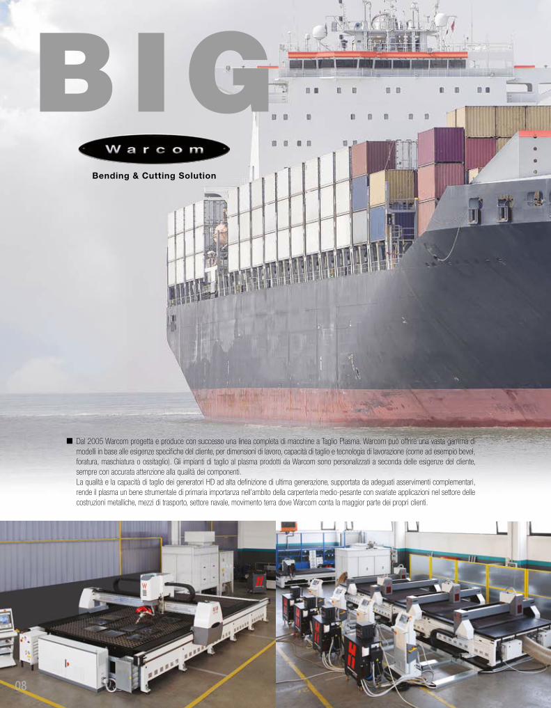
Dal 2005 Warcom progetta e produce con successo una linea completa di macchine a Taglio Plasma. Warcom può offrire una vasta gamma di modelli in base alle esigenze specifiche del cliente, per dimensioni di lavoro, capacità di taglio e tecnologia di lavorazione (come ad esempio bevel, foratura, maschiatura o ossitaglio). Gli impianti di taglio al plasma prodotti da Warcom sono personalizzati a seconda delle esigenze del cliente, sempre con accurata attenzione alla qualità dei componenti.La qualità e la capacità di taglio dei generatori HD ad alta definizione di ultima generazione, supportata da adeguati asservimenti complementari, rende il plasma un bene strumentale di primaria importanza nell’ambito della carpenteria medio-pesante con svariate applicazioni nel settore delle costruzioni metalliche, mezzi di trasporto, settore navale, movimento terra dove Warcom conta la maggior parte dei propri clienti.

09
Since 2005 Warcom successfully designs and manufactures a full line of Plasma Cutting machines. Warcom can offer a wide range of models according to the customer’s specific needs in terms of working size, cutting capacity and process technology (such as bevel, drilling, tapping or oxy-fuel). The plasma cutting system produced by Warcom are customized, according to customer’s requirements with a strong focus on the use of quality components. The quality and the cutting capacity of the last generation of HD High Definition plasma cutting power supply, supported by appropriate complementary devices, gives the plasma cutting machine a primary importance in the field of fabricating with different applications on steel construction, trucking, shipbuilding, earth moving equipment where Warcom has most of its customers.
10
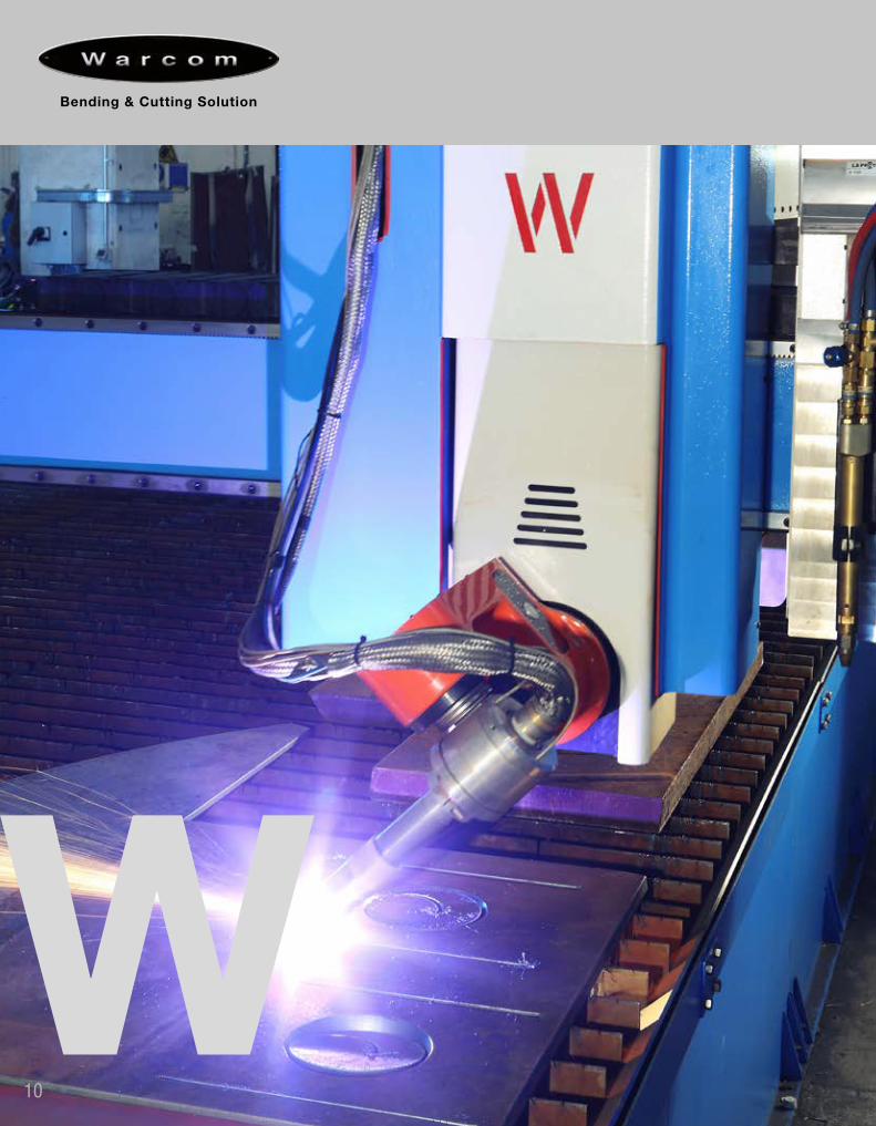
Taglio Plasma / Plasma Cutting
11

12
PLASMA CUTTING PROCESS
Plasma cutting was born from the evolution of a technology already existing that is plasma arc welding. It was realized through a system that produced a plasma jet with high energy content and it can work the surface of the workpiece, both to make surface treatment and to obtain a real welding. The inventive step that leads to plasma cutting system is marked in the patent of 1955 of Robert Gage who realized, as a result of his research, a nozzle positioned along the path of the hot plasma which forces the flow within a well-defined shape. The result of the presence of this component is a much more thin, rigid and stable jet, in order to have an high specific power able to cut metals.
PROCESSO DI TAGLIO PLASMA
Il taglio plasma nasce dall’evoluzione di una tecnologia già esistente, che è quella della saldatura tramite getto di plasma. Essa era realizzata tramite un sistema con cui si riusciva a realizzare un getto di plasma ad alto contenuto energetico in grado di lavorare la superficie del pezzo, sia per effettuare trattamenti superficiali sia per ottenere una vera e propria saldatura. Il passo inventivo che porta al taglio plasma è situato nel brevetto del 1955 di Robert Gage che realizza, a seguito delle sue ricerche, un ugello posizionato lungo il percorso del plasma caldo che ne costringe il flusso all’interno di una forma ben definita. Il risultato della presenza di questo componente è un getto molto più sottile, rigido e stabile, tale da avere una potenza specifica talmente alta da essere in grado di tagliare i metalli.
BRIEF HYSTORY ABOUT PLASMA’S PRINCIPLE OPERATION
A gas is blown at high speed through a nozzle and simultaneously is stimulated by an electric arc established between an electrode and the (metallic) surface to be cut, which transforms the gas into plasma. It transfers heat to the metal material bringing it to the melting temperature. The gas kinetic energy ejects the molten metal from the cutting area thus allowing the progress of the operation. In a first phase (piercing) a low intensity current triggers a small spark between the electrode and nozzle, generating a small glimmer of plasma, which is called arc pilot.Another piercing system, “cleaner” from the point of view of electromagnetic interference, is the contact’s trigger. This technology ensures that the electrode is in contact with the nozzle and that a current passes between these two elements in short circuit.At the passage of the electricity power, also the gas has directed, moving away the electrode from the nozzle and generating the spark ignition. In the next phase (transfer phase), plasma gets in contact with the workpiece, which represents the anode. The plasma completes the circuit between the electrode and the workpiece and leads the high-current electricity at low-voltage. The plasma that is created between the workpiece and the electrode has a speed more than 15.000 km/h (more than twelve times the speed of sound).
PLASMA CUTTING PROCESS
The plasma cutting processes can be divided into two types: conventional plasma cutting and High Definition plasma cutting. The choice of the power supply has to be made depending on the required cutting quality, the material and the thickness to be cut. Among the advantages, in addition to the improved quality of the cut, it has a longer life consumables and an increase of the piercing capacity because the high definition torch can be positioned very close to the piece as it is water-cooled.
BREVE STORIA DEL PRINCIPIO DI FUNZIONAMENTO “PLASMA”
Un gas viene soffiato ad alta velocità attraverso un ugello e contemporaneamente viene stimolato da un arco elettrico che si instaura tra un elettrodo e la superficie (metallica) da tagliare, trasformando il gas in plasma. Esso trasferisce calore al materiale metallico fino a portarlo alla temperatura di fusione. L’energia cinetica del gas espelle il metallo fuso dalla zona di taglio permettendo così il procedere dell’operazione. In una prima fase (fase d’innesco), una corrente a bassa intensità innesca una piccola scintilla tra elettrodo e ugello, generando una piccola tasca di plasma che viene chiamata arco pilota.Un altro sistema di innesco, più “pulito” dal punto di vista delle interferenze elettromagnetiche, è quello per contatto. Questa tecnologia prevede che l’elettrodo sia a contatto con l’ugello e che una corrente passi tra questi due elementi in corto circuito.Al passaggio della corrente viene indirizzato anche il gas che stacca l’elettrodo dall’ugello, generando la scintilla di innesco. Nella fase successiva (fase di trasferimento), il plasma si mette in contatto con il pezzo in lavorazione, che costituisce l’anodo. Il plasma completa il circuito fra l’elettrodo e il pezzo in lavorazione e conduce l’alta corrente elettrica a bassa tensione. Il plasma che si crea fra il pezzo in lavorazione e l’elettrodo, viaggia a più di 15.000 km/h (oltre dodici volte la velocità del suono).
PROCESSO DI TAGLIO PLASMA
I processi di taglio plasma si possono dividere in due tipologie: taglio plasma convenzionale e taglio plasma HD ad alta definizione.La scelta del generatore deve avvenire in funzione del tipo di qualità di taglio desiderata, del materiale e degli spessori da tagliare. Tra i vantaggi, oltre alla migliore qualità del taglio, si ha una maggior durata dei consumabili e l’aumento della capacità di sfondamento perché la torcia ad alta definizione può posizionarsi molto vicino al pezzo in quanto raffreddata ad acqua.
Processo di taglio plasmaPlasma cutting process

13
MATERIALIMATERIALS GAS
ACCIAI AL CARBONIO (MS)OSSIGENO - OXIGEN
ARIA - AIR
ACCIAI INOX (SS)
ARIA - AIRAZOTO - NITROGEN
ARGONIDROGENO (35%) - HYDROGEN
ALLUMINIO E L.L. (AL)
ARIA - AIRAZOTO - NITROGEN
ARGONIDROGENO (35%) - HYDROGEN
PLASMA CONVENZIONALE
CONVENTIONAL PLASMA
+
-
Gas di protezione - Protection Gas
Gas plasma Gasconsole
RHFconsole
Plasma Gas - Plasma Gas
Schermatura a gas - Shield
Positivo - Positive
Negativo - Negative
Arco pilota - Pilot arc
MATERIALIMATERIALS GAS GAS DI PROTEZIONE
PROTECTION GAS
ACCIAI AL CARBONIO (MS)OSSIGENO - OXIGEN
ARIA - AIR
OSSIGENO - OXIGENARIA - AIR
AZOTO - NITROGEN
ACCIAI INOX (SS)
ARIA - AIRAZOTO - NITROGEN
ARGONIDROGENO (35%) - HYDROGEN
ARIA - AIRAZOTO - NITROGEN
ALLUMINIO E L.L. (AL)
ARIAAZOTOARGON
IDROGENO (35%)
ARIA - AIRAZOTO - NITROGEN
HIGH DEFINITION PLASMAPLASMA AD ALTA DEFINIZIONE

14
Sottile - Thin
6 mm (1/4”)
16 mm (5/8”)
Spessoredel materiale
Requisiti di taglio di volume/taglio dettagliatoVolume/fine feature requirements
Materialthickness
50 mm (2”)
80 mm (3.2”)
Spesso - Thick
Basso volumeLow volume
Oxyfuel is limited to mild steel and is not effective on stainless steel or aluminum; multi-torchapplications may require additional consultation depending on application.
Plasma provides an optimal mix of cut quality, productivity and aperating cost for mild steel, stainlesssteel, and aluminum across a wide range of thicknesses at a competitive capital equipment price.
Laser provides excellent cut quality, productivity and operating costs on material less than 6 mm (1/4”). Depending on type of laser (C02 or Fiber) and the power level available, cut capacity can be extenden to 32 mm (11/4”). Cutting volume, types of materials, fine feature requirements and thicknesses are important considerations.
Alto volumeHigh volume
Confronto tra plasma, ossitaglio e laserComparison between plasma, oxyfuel and laser

15
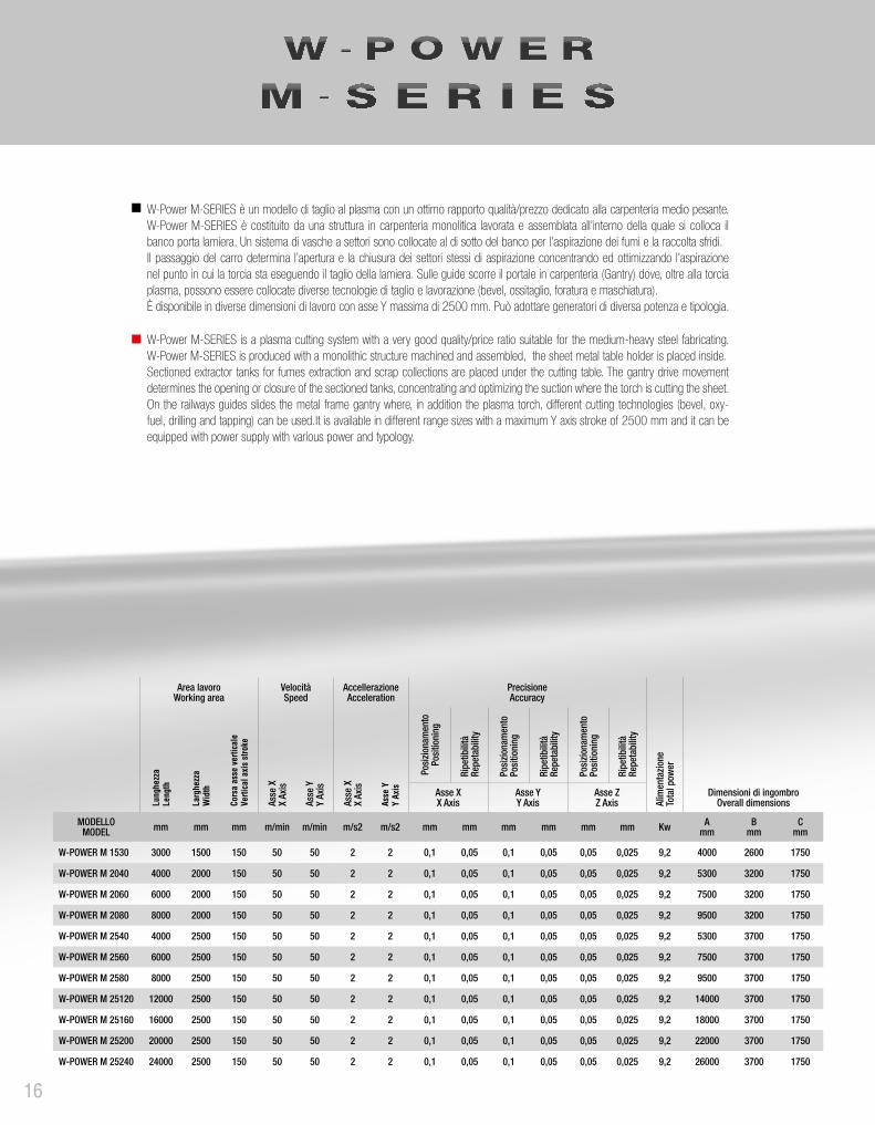
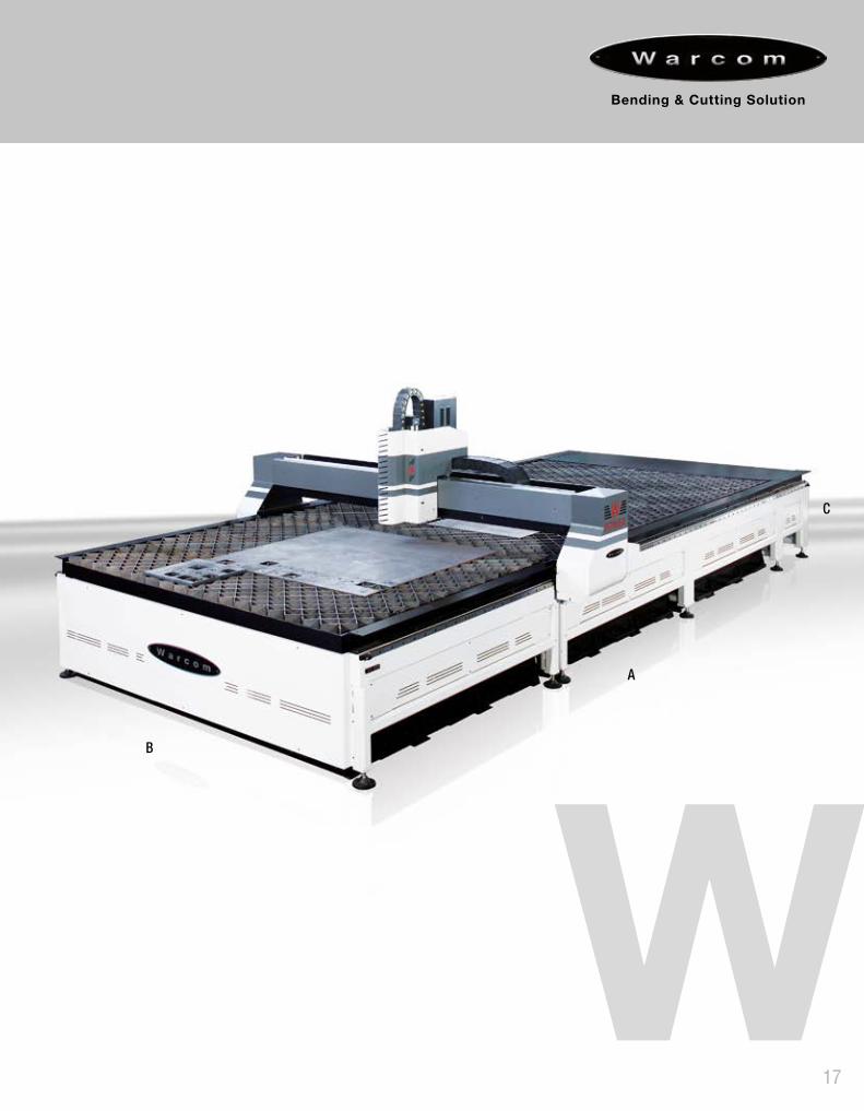
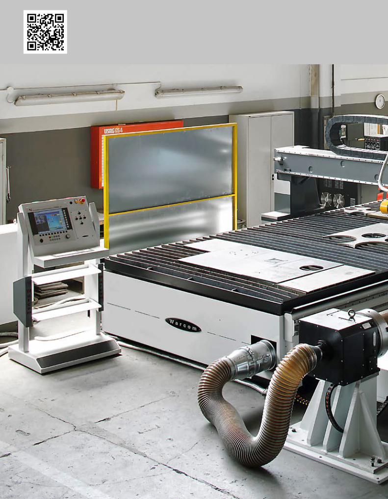
W-Power M-SERIES è un modello di taglio al plasma con un ottimo rapporto qualità/prezzo dedicato alla carpenteria medio pesante.W-Power M-SERIES è costituito da una struttura in carpenteria monolitica lavorata e assemblata all’interno della quale si colloca il banco porta lamiera. Un sistema di vasche a settori sono collocate al di sotto del banco per l’aspirazione dei fumi e la raccolta sfridi. Il passaggio del carro determina l’apertura e la chiusura dei settori stessi di aspirazione concentrando ed ottimizzando l’aspirazione nel punto in cui la torcia sta eseguendo il taglio della lamiera. Sulle guide scorre il portale in carpenteria (Gantry) dove, oltre alla torcia plasma, possono essere collocate diverse tecnologie di taglio e lavorazione (bevel, ossitaglio, foratura e maschiatura).È disponibile in diverse dimensioni di lavoro con asse Y massima di 2500 mm. Può adottare generatori di diversa potenza e tipologia.
W-Power M-SERIES is a plasma cutting system with a very good quality/price ratio suitable for the medium-heavy steel fabricating. W-Power M-SERIES is produced with a monolithic structure machined and assembled, the sheet metal table holder is placed inside.Sectioned extractor tanks for fumes extraction and scrap collections are placed under the cutting table. The gantry drive movement determines the opening or closure of the sectioned tanks, concentrating and optimizing the suction where the torch is cutting the sheet. On the railways guides slides the metal frame gantry where, in addition the plasma torch, different cutting technologies (bevel, oxy-fuel, drilling and tapping) can be used.It is available in different range sizes with a maximum Y axis stroke of 2500 mm and it can be equipped with power supply with various power and typology.
Area lavoro Working area
Velocità Speed
AccellerazioneAcceleration
PrecisioneAccuracy
Alim
enta
zion
eTo
tal p
ower
Dimensioni di ingombroOverall dimensionsLu
nghe
zza
Leng
th
Larg
hezz
aW
idth
Cors
a as
se v
ertic
ale
Verti
cal a
xis
stro
ke
Asse
XX
Axis
Asse
YY
Axis
Asse
XX
Axis
Asse
YY
Axis
Posi
zion
amen
toPo
sitio
ning
Ripe
tibili
tàRe
peta
bilit
y
Posi
zion
amen
toPo
sitio
ning
Ripe
tibili
tàRe
peta
bilit
y
Posi
zion
amen
toPo
sitio
ning
Ripe
tibili
tàRe
peta
bilit
y
Asse XX Axis
Asse YY Axis
Asse ZZ Axis
MODELLOMODEL mm mm mm m/min m/min m/s2 m/s2 mm mm mm mm mm mm Kw A
mmB
mmC
mm
W-POWER M 1530 3000 1500 150 50 50 2 2 0,1 0,05 0,1 0,05 0,05 0,025 9,2 4000 2600 1750
W-POWER M 2040 4000 2000 150 50 50 2 2 0,1 0,05 0,1 0,05 0,05 0,025 9,2 5300 3200 1750
W-POWER M 2060 6000 2000 150 50 50 2 2 0,1 0,05 0,1 0,05 0,05 0,025 9,2 7500 3200 1750
W-POWER M 2080 8000 2000 150 50 50 2 2 0,1 0,05 0,1 0,05 0,05 0,025 9,2 9500 3200 1750
W-POWER M 2540 4000 2500 150 50 50 2 2 0,1 0,05 0,1 0,05 0,05 0,025 9,2 5300 3700 1750
W-POWER M 2560 6000 2500 150 50 50 2 2 0,1 0,05 0,1 0,05 0,05 0,025 9,2 7500 3700 1750
W-POWER M 2580 8000 2500 150 50 50 2 2 0,1 0,05 0,1 0,05 0,05 0,025 9,2 9500 3700 1750
W-POWER M 25120 12000 2500 150 50 50 2 2 0,1 0,05 0,1 0,05 0,05 0,025 9,2 14000 3700 1750
W-POWER M 25160 16000 2500 150 50 50 2 2 0,1 0,05 0,1 0,05 0,05 0,025 9,2 18000 3700 1750
W-POWER M 25200 20000 2500 150 50 50 2 2 0,1 0,05 0,1 0,05 0,05 0,025 9,2 22000 3700 1750
W-POWER M 25240 24000 2500 150 50 50 2 2 0,1 0,05 0,1 0,05 0,05 0,025 9,2 26000 3700 1750
16
17
18
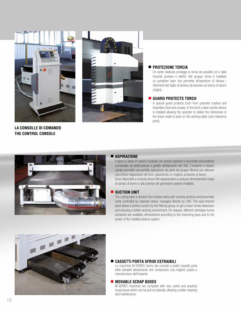
LA CONSOLLE DI COMANDOTHE CONTROL CONSOLE
PROTEZIONE TORCIAUn carter dedicato protegge la torcia da possibili urti e dalle impurità (polvere e detriti). Nel gruppo torcia è installato un puntatore laser che permette all’operatore di rilevare i riferimenti del foglio di lamiera da lavorare sul banco di lavoro (origini).
GUARD PROTECTS TORCHA special guard protects torch from potential crashes and impurities (dust and scraps). In the torch a laser pointer device is installed allowing the operator to detect the references of the sheet metal to work on the working table (zero reference point).
ASPIRAZIONEIl banco è diviso in vasche modulari con sezioni aspiranti e bocchette pneumatiche comandate da elettrovalvole e gestite direttamente dal CNC. L’impianto a doppio canale permette una perfetta aspirazione da parte del gruppo filtrante per ottenere una minore dispersione dei fumi, garantendo un migliore ambiente di lavoro.Sono disponibili a richiesta diversi filtri depolveratori a cartucce dimensionati in base al campo di lavoro e alla potenza del generatore plasma installato.
SUCTION UNITThe cutting table is divided into modular tanks with sucking sections and pneumatic vents controlled by solenoid valves, managed directly by CNC. The dual-channel plant allows a perfect suction by the filtering group, to get a lower fumes dispersion and ensuring a better working environment. On request, different cartridges fumes extractors are available, dimensioned according to the machining sizes and to the power of the installed plasma system.
CASSETTI PORTA SFRIDI ESTRAIBILILe macchine M-SERIES hanno dei comodi e pratici cassetti porta sfridi estraibili lateralmente che consentono una migliore pulizia e manutenzione dell’impianto.
MOVABLE SCRAP BOXESM-SERIES machines are complete with very useful and practical scrap boxes which can be pull out laterally, allowing a better cleaning and maintenance.

19
20
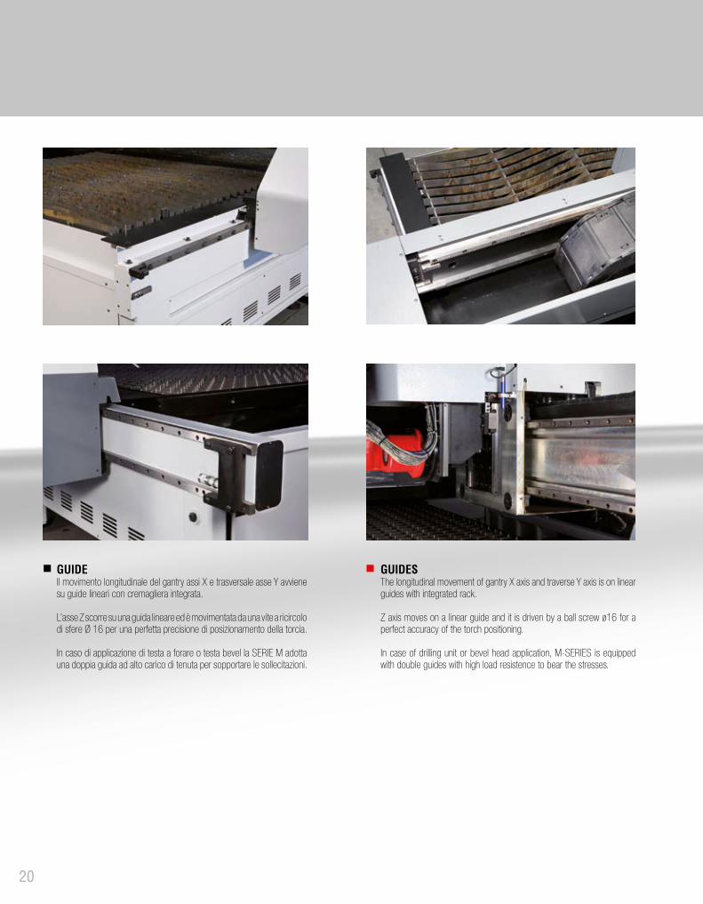
GUIDES The longitudinal movement of gantry X axis and traverse Y axis is on linear guides with integrated rack.
Z axis moves on a linear guide and it is driven by a ball screw ø16 for a perfect accuracy of the torch positioning.
In case of drilling unit or bevel head application, M-SERIES is equipped with double guides with high load resistence to bear the stresses.
GUIDEIl movimento longitudinale del gantry assi X e trasversale asse Y avviene su guide lineari con cremagliera integrata.
L’asse Z scorre su una guida lineare ed è movimentata da una vite a ricircolo di sfere Ø 16 per una perfetta precisione di posizionamento della torcia.
In caso di applicazione di testa a forare o testa bevel la SERIE M adotta una doppia guida ad alto carico di tenuta per sopportare le sollecitazioni.
21
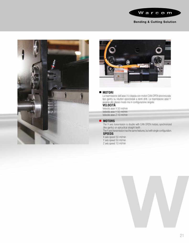
MOTORSThe X axis transmission is double with CAN OPEN motors, synchronized (like gantry) on epicyclical straight teeth .The Y axis transmission has the same features, but with single configuration.SPEEDSX axis speed 50 mt/min Y axis speed 50 mt/minZ axis speed 10 mt/min
MOTORILa trasmissione dell’asse X è doppia con motori CAN OPEN sincronizzata tipo gantry su riduttori epicicloidali a denti dritti. La trasmissione asse Y avviene allo stesso modo ma in configurazione singola.VELOCITÀ Velocità asse X 50 mt/minVelocità asse Y 50 mt/minVelocità asse Z 10 mt/min

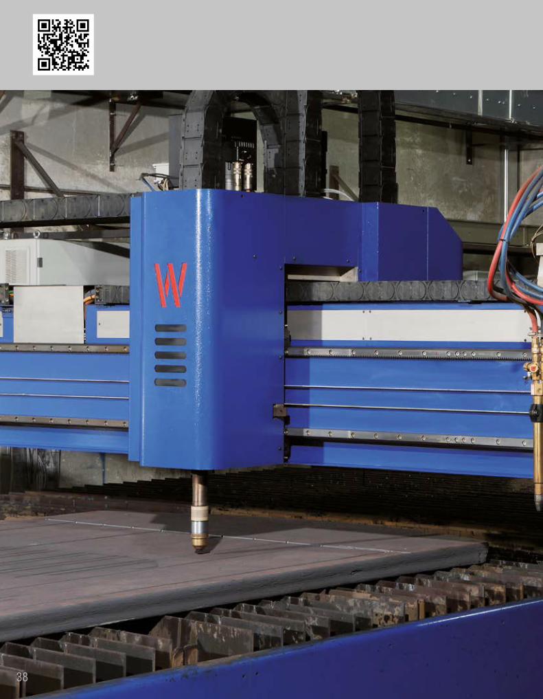
W-Power S-SERIES è anch’esso dedicato alla carpenteria medio-pesante ma con dimensioni maggiori rispetto alla M-SERIES. Rappresenta il modello più versatile della categoria, con ampie possibilità di applicazioni (taglio inclinato per smussi, ossitaglio, foratura e maschiatura). Viene solitamente proposto per larghezze minime da 3 m in quanto utilizza una struttura con guide indipendenti fissate a terra. Le guide fissate a terra sono modulari per facilitare l’installazione anche di impianti con lunghezze importanti. Il banco porta lamiere modulare a settori aspiranti parzializzati è separato dalla macchina ed è disponibile in diverse versioni a seconda del tipo di lavoro.
W-Power S-SERIES is dedicated at medium-heavy steel fabricating and has bigger working sizes compared to M-SERIES. It represents the most versatile model in its range with many applications opportunities (bevel, oxyfuel, drilling, tapping). It is usually proposed for minimum widths from 3 m as it has a structure with independent guides fixed on floor. Guides fixed on floor are modular, facilitating the installation of plants with very long length. The modular support working table for sheet metal with throttled suction sections is independent from the machine and it is available in different versions according to the work which has to be done.
Area lavoro Working area
Velocità Speed
AccellerazioneAcceleration
Precisione Accuracy
Alim
enta
zion
eTo
tal p
ower
Dimensioni di ingombroOverall dimensionsLu
nghe
zza
Leng
th
Larg
hezz
aW
idth
Cors
a as
se v
ertic
ale
Verti
cal a
xis
stro
ke
Asse
XX
Axis
Asse
YY
Axis
Asse
XX
Axis
Asse
YY
Axis
Posi
zion
amen
toPo
sitio
ning
Ripe
tibili
tàRe
peta
bilit
y
Posi
zion
amen
toPo
sitio
ning
Ripe
tibili
tàRe
peta
bilit
y
Posi
zion
amen
toPo
sitio
ning
Ripe
tibili
tàRe
peta
bilit
y
Asse XX Axis
Asse YY Axis
Asse ZZ Axis
MODELLOMODEL mm mm mm m/min m/min m/s2 m/s2 mm mm mm mm mm mm Kw A
mmB
mmC
mm
W-POWER S 3060 6000 3000 300 50 50 2 2 0,1 0,05 0,1 0,05 0,05 0,025 9,2 8000 4200 1750
W-POWER S 3080 8000 3000 300 50 50 2 2 0,1 0,05 0,1 0,05 0,05 0,025 9,2 10000 4200 1750
W-POWER S 30120 12000 3000 300 50 50 2 2 0,1 0,05 0,1 0,05 0,05 0,025 9,2 14000 4200 1750
W-POWER S 30160 16000 3000 300 50 50 2 2 0,1 0,05 0,1 0,05 0,05 0,025 9,2 18000 4200 1750
W-POWER S 30200 20000 3000 300 50 50 2 2 0,1 0,05 0,1 0,05 0,05 0,025 9,2 23500 4200 1750
W-POWER S 30240 24000 3000 300 50 50 2 2 0,1 0,05 0,1 0,05 0,05 0,025 9,2 26000 4200 1750
W-POWER S 4060 6000 4000 300 50 50 2 2 0,1 0,05 0,1 0,05 0,05 0,025 9,2 8000 5200 1750
W-POWER S 4080 8000 4000 300 50 50 2 2 0,1 0,05 0,1 0,05 0,05 0,025 9,2 10000 5200 1750
W-POWER S 40120 12000 4000 300 50 50 2 2 0,1 0,05 0,1 0,05 0,05 0,025 9,2 14000 5200 1750
W-POWER S 40160 16000 4000 300 50 50 2 2 0,1 0,05 0,1 0,05 0,05 0,025 9,2 18000 5200 1750
W-POWER S 40200 20000 4000 300 50 50 2 2 0,1 0,05 0,1 0,05 0,05 0,025 9,2 23500 5200 1750
W-POWER S 40240 24000 4000 300 50 50 2 2 0,1 0,05 0,1 0,05 0,05 0,025 9,2 26000 5200 1750
22

23

24

25

26
CONTROLLO ALTEZZA TORCIA (THC)La torcia è protetta da possibili urti e impurità (polvere e detriti). Nel gruppo torcia è installato un puntatore laser che permette all’operatore di rilevare i riferimenti del foglio di lamiera da lavorare sul banco di lavoro (origini). La torcia ha un sistema automatico di controllo altezza (THC) che mantiene la distanza tra ugello e materiale costante, seguendo la superfice della lamiera. La torcia possiede un efficace sistema di anticollisione che permette il blocco immediato della macchina in qualsiasi caso di emergenza.
TORCH HEIGHT CONTROL (THC)Torch is protected by potential crashes and impurities (dust and scraps). In the torch a laser pointer device is installed allowing the operator to detect the references of the sheet metal to work on the working table (zero reference point).The torch has an automatic Torch Height Control (THC) that maintains constant the distance between the nozzle and material, following the sheet metal surface. The torch has an effective anti-collision system, which allows the immediate stop of the machine in case of emergency.
MOVIMENTAZIONE A DISTANZAUn comodo telecomando consente di effettuare spostamenti rapidi della torcia per ottimizzare il nesting. Su banchi lunghi è disponibile in versione wireless.
REMOTE CONTROLAn easy control allows to make quick movement of the torch to optimize the nesting. For long machines a wireless version is available.
GUIDES SYSTEM FIXED ON THE FLOORThe guides system for the movement of X axis gantry is placed directly on the floor and set by leveling and alignment devices. On special machine with drilling unit or particular cutting technologies, the guides are double bacause of the increased stress which is subject the gantry.
GRUPPO GUIDE A TERRALe guide per il movimento del portale asse X vengono fissate direttamente a terra e regolate con dispositivi di livellamento e allineamento.Su impianti particolarmente complessi dove viene applicata l’unità di foratura o altre tecnologie di taglio particolari, le guide di scorrimento sono doppie a causa delle maggiori sollecitazioni a cui è sottoposto il gantry.
CONSOLE A BORDO MACCHINAPer macchine di grandi dimensioni si consiglia di montare la gas console sul gantry, soprattutto per ridurre la distanza con la torcia di taglio. La gas console può essere manuale (standard) o, a richiesta, automatica gestita dal CNC.
CONSOLE ON THE GANTRYFor machines of big sizes, it is suggested to install the gas console on the gantry, mainly to reduce the distance between the console and the cutting torch. The gas console can be either manual (standard version) or, on request, automatic controlled by CNC.
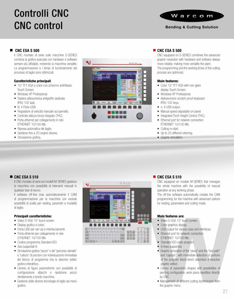
CNC ESA S 510Il CNC montato di serie sui modelli M-SERIES gestisce la macchina con possibilità di interventi manuali in qualsiasi fase di lavoro.Il software off-line crea automaticamente il CAM di programmazione per la macchina con evolute possibilità di scelta per nesting, parametri e modalità di taglio.
Principali caratteristiche:• Video S-VGA 15” touch screen.• Display grafico a colori.• Porta USB per vari usi e interfacciamenti.• Porta ethernet per collegamento in rete ETHERNET 10/100 Mb.• Codice programma Standard ISO.• Assi supportati 8.• Simulazione grafica “pezzo” e del “percorso utensile” e “cattura” di porzioni con individuazione immediata del blocco di programma che le descrive (editor grafico interattivo).• Libreria di figure parametriche con possibilità di configurazione attacchi e ripetizione pezzo direttamente a bordo macchina.• Gestione delle diverse tecnologie di taglio da menù grafico.
Controlli CNCCNC control
27
CNC ESA S 500Il CNC montato di serie sulle macchine S-SERIES combina la grafica avanzata con hardware e software sempre più affidabili, rendendo la macchina versatile. La programmazione e i tempi di funzionamento del processo di taglio sono ottimizzati.
Caratteristiche principali• 15” TFT XGA a colori con schermo antiriflesso Touch Screen.• Windows XP Professional.• Tastiera alfanumerica antigraffio dedicata IP65 102 tasti.• N. 4 Porte USB.• Regolatore di velocità manuale sul pannello.• Controllo altezza torcia integrato (THC).• Porta ethernet per collegamento in rete ETHERNET 10/100 Mb.• Ripresa automatica del taglio.• Gestione fino a 20 origine diverse.• Simulazione grafica.
CNC ESA S 500CNC equipped on S-SERIES combines the advanced graphic resolution with hardware and software always more reliable, making more versatile the plant. The programming and the working times of the cutting process are optimized.
Main features:• Color 15” TFT XGA with non-glare display Touch Screen.• Windows XP Professional.• Alphanumeric scratch-proof keyboard IP65 102 keys.• n. 4 USB output.• Manual speed adjustable on panel.• Integrated Torch Height Control (THC).• Ethernet port for network connection ETHERNET 10/100 Mb. • Cutting re-start.• Up to 20 different referring.• Graphic simulation.
CNC ESA S 510CNC equipped on models M-SERIES that manages the whole machine with the possibility of manual operation at any working phase. The off-line software automatically creates the CAM programming for the machine with advanced options for nesting, parameters and cutting mode.
Main features are:• Video S-VGA 15” touch screen. • Color graphics display. • USB output for various uses and interfaces. • Ethernet port for network connection ETHERNET 10/100 Mb. • Standard ISO code program. • 8 Axes supported. • Graphic simulation of the “piece” and the “tool path” and “capture” with immediate detection of portions of the program block which describes (interactive graphic editor). • Library of parametric shapes with possibilities of piercing configuration, work piece repetition directly by CNC. • Management of different cutting technologies from the graphic menu.

Asse AA axis
Asse BB axis
Input ServomotoreServomotor Input
Nm/rpm 1 Nm / 5000 rpm 0.7 Nm / 6000 rpm
EncoderIncrementale / assolutoIncremental / absolute
Incrementale / assolutoIncremental / absolute
Angolo assiAxis angle
(°) + /- 48° + /- 48°
Forza di torsione nominale in continuoContinuosly torsion force
Nm 124 144
VelocitàSpeed
rpm 40 29
Dimensione e pesoDimension and weight
mmKg
H 370 + W170 - T15034Kg
Taglio BevelBevel cutting head
28
UNITÀ DI TAGLIO BEVELLa testa 3D comporta l’aggiunta del 4° e 5° asse alla normale configurazione del portale e consente di eseguire tagli inclinati programmabili fino ad un massimo di 45° in tutti i sensi di lavorazione. La particolare conformazione della testa consente una rotazione a 360° garantendo l’integrità delle tubazioni dei gas e cavi elettrici.
BEVEL CUTTING HEADThe 3D cutting head involves the addition of the 4th and 5th axis to the standard configuration of the gantry and allows to execute inclined cutting, programmable up to a maximum of 45° in all working directions. The particular shape of the head allows a 360° rotation, guaranteeing the gas pipes and electrical cable integrity.
ANTI - CRASH DEVICE (only bevel)The new torch holder adopts a new anti-collision system with coupling / uncoupling magnetic quick release signaled by dual color LEDs very practical and intuitive.The system is extremely precise stopping the machine in a very short time.
ANTICOLLISIONE (solo bevel)Il nuovo supporto torcia adotta un nuovissimo sistema anticollisione con aggancio/sgancio magnetico ad innesto rapido segnalato tramite led doppio colore molto pratici ed intuitivi.Il sistema risulta estremamente preciso fermando con tempi di arresto rapidissimi.

OXYFUELW-Power S-SERIES and M-SERIES allow to combine plasma technology with oxyfuel. The machine can be equipped either with the main torch only (MASTER) or with MASTER and additional torches SLAVE, movable in parallel to the MASTER one. This configuration allows the repetitive cutting in parallel. The application by the oxy-fuel involves to increase the height of the gantry to ease the heat loss generated by the cutting process. In case of more oxyfuel torches (SLAVE), the machine can be equipped with manual or automatic positioning. The gas mixing plant is controlled by manual or proportional solenoid valves managed by CNC according to customer’s requirements. As option, oxyfuel torches can be supplied with automatic starting and capacitive sensors for an automatic height control.
OSSITAGLIOW-Power S-SERIES e M-SERIES consentono di combinare alla tecnologia a taglio plasma la tecnologia ossitaglio. Può essere montata la sola unità di taglio principale (MASTER) oppure l’unità MASTER con l’aggiunta di unità di taglio SLAVE movimentabili in parallelo al MASTER. Questa configurazione permette il taglio ripetitivo in parallelo.L’applicazione con la torcia ossitaglio (comunemente chiamata cannello) comporta l’innalzamento del carro per agevolare la dispersione del calore generato dal processo di taglio. In caso di torce multiple (SLAVE) si può dotare la macchina di impacchettamento manuale o automatico. L’impianto di miscelazione dei gas è gestito con elettrovalvole manuali o elettrovalvole proporzionali gestite dal CNC a seconda dell’esigenza del cliente. A richiesta può essere fornita l’accessione automatica delle torce e i sensori capacitivi per il controllo automatico di altezza.
29
OssitaglioOxyfuel
TORCIA OSSITAGLIO (comunemente chiamato “Cannello”)Ogni cannello ossitaglio dispone di una movimentazione verticale manuale regolabile dall’operatore. L’accensione del cannello è manuale. La configurazione standard non include il sensore capacitivo. A richiesta si possono applicare sia l’accensione automatica che il controllo altezza torcia THC a controllo capacitivo. L’impostazione dell’off-set tra i cannelli SLAVE ed il cannello Master avviene manualmente con la possibilità a richiesta della gestione automatica a CNC.
OXYFUEL TORCH Every oxyfuel torch has a vertical manual adjustment, by the operator. The oxyfuel torch has manual starting without capacitive sensor (in standard configuration). Upon request, the automatic starting and the THC with capacitive control are available. The off-set setting between the SLAVE torches and the Master one is made manually, upon request of an automatic control by CNC.
MISCELAZIONE DEI GASLa miscelazione dei gas e la gestione dei tempi ciclo (riscaldo e taglio) avviene attraverso delle elettrovalvole temporizzate. A richiesta, sono disponibili elettrovalvole proporzionali gestite dal CNC per automatizzare al massimo il processo. Serve prestare particolare attenzione alla portata dell’impianto gas in quanto a parità di portata la capacità di taglio (in termini di spessore) cambia, a seconda che il flusso venga indirizzato su un cannello singolo o multipli.
GAS MIXINGThe gas mixing and the management of the cycle time (heating and cut) is made through timed solenoid valves. Upon request, also the proportional solenoid valves controlled by CNC and by software are available, in order to automate and optimize the cutting process. It is important to keep attention to the flow capacity of the gas plant, because by the same flow, the cutting capacity (in terms of thickness) changes depending if the available flow is use on a single torch or multiple ones.

Foratura / MaschiaturaDrilling / Tapping
30
UNITÀ DI FORATURA/MASCHIATURAL’installazione di una testa a forare include:• Testa a forare ISO30/ISO40 con mandrino da 8000 rpm (Ø max 30 mm – filetto max M27).• Unità premi lamiera.• Adattamento strutturale del portale.• Banco tipo pesante.• Impianto di nebulizzazione.• Impianto di soffiatura.
DRILLING/TAPPING UNITThe application of the drilling unit:• Drilling head ISO30/ISO40 with spindle of 8000 rpm (Ø max 30 mm – thread max M27).• Hold down units.• Structural adjustment of the gantry.• Special sturdy bench.• Nebulizer device.• Pneumatic blower device.
UNITÀ DI FORATURA PNEUMATICAUnità di foratura pneumatica semplice ed economica (disponibile per tutte le macchine plasma Warcom) installata in off-set accanto alla torcia plasma. Ideale per lavorazioni di bulinatura e foratura fino a max Ø 6 mm.
PNEUMATIC DRILL UNITPneumatic drill unit simple and cheap (available on all Warcom’s plasma machines), installed in off-set near to the plasma torch.Suitable for chasing and drilling up to Ø 6 mm.
UNITÀ DI BULINATURACHASING UNIT

31
CAMBIO UTENSILI AUTOMATICOCon l’unità di foratura è possibile equipaggiare la macchina con un cambio utensili automatico, composto da un magazzino a scomparsa nel banco di lavoro. Il magazzino è disponibile nella versione da 6 o 12 stazioni.
AUTOMATIC TOOL CHANGERIn case of application of the drilling unit, the machine can be equipped with an automatic tool changer, composed by a device disappearing in the working table. The tool changer is available in the version with 6 or 12 positions.
BENCH HEAVY TYPEIn case a drilling head unit is installed on plasma machine, a special heavy working table is equipped on the machine, in order to bear the mechanical stresses typical of the drilling operations and to avoid the breakage of the tools.The grate can be composed by crossed sheets with pins in mild steel, according to customer preference.
BANCO TIPO PESANTEIn caso d’installazione di una testa a forare è necessario equipaggiare la macchina con un banco serie pesante che possa sopportare le sollecitazioni meccaniche della foratura ed evitare la rottura degli utensili. Il grigliato può essere con lamiere a puntali intrecciate o pioli in acciaio tenero a scelta del cliente.

W-Tube
32
W-Tube device consists of an extension cantilever of the beam that allows the torch to cut pipes of round section supported by n. 2 retaining rests motorized on two axes in order to suit different diameters.
In top of the rests there is the motor spindle (rotary axis) that allows to work up to 600 mm diameter tubes.
Il dispositivo W-Tube consiste in un prolungamento a sbalzo della trave porta torcia per tagliare tubi di sezione tonda alloggiati su n. 2 lunette motorizzate su 2 assi in modo da sostenere diversi diametri.
In testa alle lunette si trova il mandrino motorizzato (asse rotativo), che consente di lavorare tubi di diametro massimo 600 mm.
33
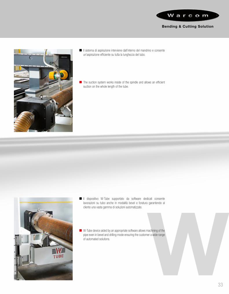
The suction system works inside of the spindle and allows an efficient suction on the whole length of the tube.
Il sistema di aspirazione interviene dall’interno del mandrino e consente un’aspirazione efficiente su tutta la lunghezza del tubo.
W-Tube device aided by an appropriate software allows machining of the pipe even in bevel and drilling mode ensuring the customer a wide range of automated solutions.
Il dispositivo W-Tube supportato da software dedicati consente lavorazioni su tubo anche in modalità bevel e foratura garantendo al cliente una vasta gamma di soluzioni automatizzate.
34

35
36

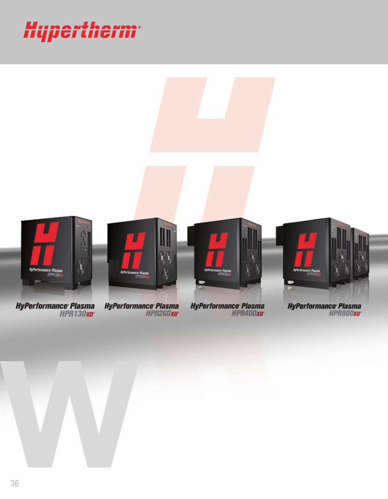
GENERATORI PLASMA PLASMA POWER SUPPLY
POTENZAPOWER
TIPOTYPE
L-SERIES M-SERIES S-SERIES CAPACITA DI TAGLIO MASSIMA
MAX CUTTING CAPACITY
FE INOX
HYPERTHERM POWERMAX 45 45 A AIR • • 12 10
HYPERTHERM POWERMAX 65 65 A AIR • • 16 12
HYPERTHERM POWERMAX 95 95 A AIR • • 20 16
HYPERTHERM POWERMAX 105 105 A AIR • • 22 20
HYPERTHERM HSD 130 130 A AIR/O2 • • 25 20
HYPERTHERM MAXPRO 200 200 A AIR/O2 • • 32 25
HYPERTHERM HPR 130XD 130 A HD • • 32 20
HYPERTHERM HPR 260XD 260 A HD • • 38 32
HYPERTHERM HPR 400XD 400 A HD • • 50 45
HYPERTHERM HPR 800XD 800 A HD • • 50 75
VICTOR CUT MASTER 40 A 40 A AIR • • 10 8
VICTOR CUT MASTER 60 A 60 A AIR • • 15 12
VICTOR CUT MASTER 80 A 80 A AIR • • 18 16
VICTOR CUT MASTER 120 A 120 A AIR • • 22 20
VICTOR AUTOCUT 200XT 200 A AIR/O2 • • 35 30
VICTOR AUTOCUT 300XT 300 A AIR/O2 • • 40 35
VICTOR ULTRACUT 100 XT 100 A HD • • • 15 15
VICTOR ULTRACUT 200XT 200 A HD • • 35 25
VICTOR ULTRACUT 300XT 300 A HD • • 45 30
VICTOR ULTRACUT 400XT 400 A HD • • 50 45
KJELLBERG HI-FOCUS 80i 80 A HD • • • 15 15
KJELLBERG HI-FOCUS 130 130 A HD • • 25 20
KJELLBERG HI-FOCUS 161i 160 A HD • • 32 25
KJELLBERG HI-FOCUS 280i 280 A HD • • 40 35
KJELLBERG HI-FOCUS 360i 360 A HD • • 50 45
KJELLBERG HI-FOCUS 440i 440 A HD • • 50 50
Generatori plasma disponibiliAvailable plasma power supply
37
38

39

Il processo di cesoiaturaThe shearing process
40
La cesoiatura è un processo meccanico attraverso il quale una lamiera viene tagliata (cesoiata) tra due lame opposte. Il materiale viene bloccato con dei cilindri idraulici premi lamiera. La lama superiore scende verso una lama inferiore fissa con l’interspazio dovuto. La lama superiore ha un’inclinazione rispetto a quella inferiore definito come angolo di taglio.Questa inclinazione permette di cesoiare il materiale progressivamente dal lato destro della macchina e ridurre la forza necessaria per tagliare il materiale.
La cesoia a ghigliottina è caratterizzata dalle seguenti principali specifiche tecniche:
PROFILO DELLA LAMA DI TAGLIO(spoglia di taglio)Influenza leggermente la forza di taglio. L’utilizzo di lame con un profilo a 90° richiede una forza di taglio maggiore rispetto all’utilizzo di lame rettificate con una leggera angolazione (solitamente di 3°).
ANGOLO DI TAGLIOL’angolo di taglio influisce molto sulla forza di taglio utilizzata e sulla distorsione del materiale cesoiato specialmente per tagli di strisce strette di lamiera. Con l’aumentare dell’inclinazione della lama superiore, la forza necessaria al taglio diminuisce, ma aumenta la distorsione del pezzo tagliato.
INTERSPAZIO LAMEÈ la distanza reale tra il filo tagliente delle due lame di taglio.L’interspazio influisce sulla qualità del taglio in relazione allo spessore della lamiera e alla resistenza del materiale. I giusti parametri per il taglio sono determinati per ogni caso specifico.Se l’interspazio è troppo stretto, aumenta l’usura degli utensili e quindi il costo di manutenzione. La forza di taglio richiesta è maggiore.Se l’interspazio è troppo ampio, il materiale tende ad essere strappato tra le due lame. Il risultato sarà un bordo tagliato con maggiore deformazione. Ecco perché l’interspazio delle lame è un fattore chiave per la qualità del taglio e la durata delle lame nel processo di cesoiatura.
The shearing is a mechanical process through which a sheet metal is cut (sheared) between two opposing blades.The material has to be blocked with hold down unit cylinders.The upper blade goes down towards a fixed lower blade with the right blade clearance.The upper blade has one tilt referring to the lower blades called cutting angle. This tilt on the upper blade permits to cut the material from the right machine’s side and to reduce the force required to cut.
The guillotine shear is characterized by the following main technical specifications:
SHEARING BLADE SHAPEThe blade shape influences the cutting force.The use of the squared 90° edge blade requires a greater cutting force compared to use a grounded upper blade with an angle (usually 3°).
CUTTING ANGLEThe cutting angle greatly affects on the cutting force required and on the shear distortion of the material sheared especially for narrow strips of sheet metal. With the increase of the inclination of the upper blade the force required to cut decreases but increases the distortion of the workpiece.
BLADE CLEARANCEIt is the real distance between the cutting edges of the two blades. The blade clearance affects the quality of the cut in relation to the sheet thickness and the strength of the material. The right cutting parameters are determined for each specific case. If the blade clearance is too narrow, the wear of the blades increases and then, the maintenance cost. The cutting force required is greater. If the gap is too large, the material tends to be torn between the two blades. The result will be a cut edge with greater deformation. That’s why the blade clearance is a keyfactor for the cutting quality and the life of blades in the shearing process.
41
Per eseguire un ottimo taglio è necessaria una cesoia idonea che possa minimizzare gli effetti che si ripercuotono su una lamiera durante un’azione di taglio. A causa della composizione interna della lamiera, delle tensioni accumulate durante la laminazione e delle caratteristiche chimiche, la lamiera tagliata subisce effetti fisici che, se non correttamente compensati, possono diventare difetti sul prodotto finito.
GLI EFFETTI NEGATIVI PIÙ COMUNI SONO: • Effetto di torsione.• Errore di linearità.• Effetto flessione.• Bordo tagliato non uniforme.
EFFETTO TORSIONEQuando la larghezza della striscia di lamiera da tagliare è inferiore a 10 volte lo spessore, le tensioni interne tendono a far assumere alla stessa una forma “elicoidale” (torsione di taglio). Questo fenomeno si amplifica aumentando l’angolo d’inclinazione del taglio. Per ridurre questo fenomeno, è necessario avere una cesoia che possa tagliare la striscia minima di materiale richiesta con un angolo minimo, oppure installare un dispositivo “anti-twisting” (opzionale). L’anti-twinsting è un dispositivo costituito da una serie di cilindri idraulici situati vicino alla lama inferiore che creano una contro forza alla lama superiore durante la fase di discesa del taglio. Questo fenomeno compensa l’effetto della torsione della lamiera stessa.
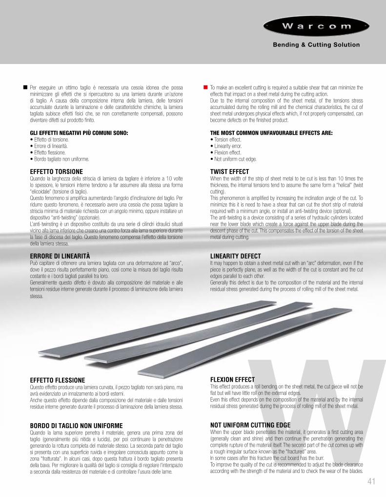
ERRORE DI LINEARITÀPuò capitare di ottenere una lamiera tagliata con una deformazione ad “arco”, dove il pezzo risulta perfettamente piano, così come la misura del taglio risulta costante e i bordi tagliati paralleli tra loro.Generalmente questo difetto è dovuto alla composizione del materiale e alle tensioni residue interne generate durante il processo di laminazione della lamiera stessa.
EFFETTO FLESSIONEQuesto effetto produce una lamiera curvata, il pezzo tagliato non sarà piano, ma avrà evidenziato un innalzamento ai bordi esterni.Anche questo effetto dipende dalla composizione del materiale e dalle tensioni residue interne generate durante il processo di laminazione della lamiera stessa.
BORDO DI TAGLIO NON UNIFORMEQuando la lama superiore penetra il materiale, genera una prima zona del taglio (generalmente più nitida e lucida), per poi continuare la penetrazione generando la rottura completa del materiale stesso. La seconda parte del taglio si presenta con una superficie ruvida e irregolare conosciuta appunto come la zona “fratturata”. In alcuni casi, dopo questa frattura il bordo tagliato presenta della bava. Per migliorare la qualità del taglio si consiglia di regolare l’interspazio a seconda dalla resistenza del materiale e di controllare l’usura delle lame.
To make an excellent cutting is required a suitable shear that can minimize the effects that impact on a sheet metal during the cutting action. Due to the internal composition of the sheet metal, of the tensions stress accumulated during the rolling mill and the chemical characteristics, the cut of sheet metal undergoes physical effects which, if not properly compensated, can become defects on the finished product.
THE MOST COMMON UNFAVOURABLE EFFECTS ARE: • Torsion effect.• Linearity error.• Flexion effect.• Not uniform cut edge.
TWIST EFFECTWhen the width of the strip of sheet metal to be cut is less than 10 times the thickness, the internal tensions tend to assume the same form a “helical” (twist cutting). This phenomenon is amplified by increasing the inclination angle of the cut. To minimize this it is need to have a shear that can cut the short strip of material required with a minimum angle, or install an anti-twisting device (optional). The anti-twisting is a device consisting of a series of hydraulic cylinders located near the lower blade which create a force against the upper blade during the descent phase of the cut. This compensates the effect of the torsion of the sheet metal during cutting.
LINEARITY DEFECTIt may happen to obtain a sheet metal cut with an “arc” deformation, even if the piece is perfectly plane, as well as the width of the cut is constant and the cut edges parallel to each other. Generally this defect is due to the composition of the material and the internal residual stress generated during the process of rolling mill of the sheet metal.
FLEXION EFFECT This effect produces a roll bending on the sheet metal, the cut piece will not be flat but will have little roll on the external edges. Even this effect depends on the composition of the material and by the internal residual stress generated during the process of rolling mill of the sheet metal.
NOT UNIFORM CUTTING EDGE When the upper blade penetrates the material, it generates a first cutting area (generally clean and shine) and then continue the penetration generating the complete rupture of the material itself. The second part of the cut comes up with a rough irregular surface known as the “fractured” area. In some cases after this fracture the cut board has the burr. To improve the quality of the cut is recommended to adjust the blade clearance according with the strength of the material and to check the wear of the blades.
42
Cesoie a GhigliottinaGuillotine Shears
43

44
PRIMA è una rivoluzionaria cesoia a ghigliottina oleodinamica prodotta da Warcom per competere con i migliori costruttori mondiali del settore.È il prodotto ideale per i clienti più esigenti in quanto adotta di serie soluzioni tecniche all’avanguardia come: CNC a 3 assi modello WarcomEvo per la gestione automatica di angolo, interspazio e registro posteriore, struttura robusta con il porta lama guidato su tutta la lunghezza, registro ribaltabile, banco pieno con sfere di scorrimento. Questo allestimento di serie rende PRIMA una cesoia studiata per lavori intensi di qualità (centro servizi, contoterzisti, impianti di cesoiatura automatici).
PRIMA is a revolutionary hydraulic guillotine shear produced by Warcom to compete with the best manufacturers worldwide. This is the best product for the most demanding customers since it has high technical solutions as follows: 3 axis CNC model WarcomEvo for the automatic management of rake angle, blade clearance and backgauge, sturdy structure with the upper blade holder driven by guides over its whole length, backgauge lifting device, full flat bench with balls transfer. This standard equipment makes PRIMA a shear designed for intensive work quality (services center, job-shop, automatic cutting system).
Lung
hezz
a di
tagl
ioCu
tting
leng
ht
Pass
aggi
o tra
i m
onta
nti
Dist
ance
bet
wee
n ho
usin
g
Prof
ondi
tà in
cavo
nei
mon
tant
iTh
roat
Capa
cità
di t
aglio
R=4
8kg/
mm
2 no
min
ale/
mas
sim
oCu
tting
cap
acity
R=4
8kg/
sq.m
mno
min
al/m
axim
um
Spes
sore
nom
inal
eNo
min
al th
ickn
ess
Ango
lo n
omin
ale
Nom
inal
ang
le
Rego
lazi
one
ango
lo d
i tag
lioCu
tting
ang
le a
djus
tmen
t
Cors
a re
gist
ro p
oste
riore
Back
gaug
e st
roke
Colp
i al 1
’St
roke
rs/m
in
Pote
nza
mot
ore
prin
cipa
leM
ain
mot
or p
ower
Peso
app
ross
imat
ivo
Appr
ox.w
eigh
t
Dimensioni di ingombroOverall dimensions
MODELLO - MODEL mm mm mmNom Max
mmmm
gradidegrees
gradidegrees
mm N° Kw KgA
mm.B
mm.C
mm.D
mm.
PRIMA 30-4PRIMA 30-6PRIMA 30-8PRIMA 30-10PRIMA 30-13PRIMA 30-16PRIMA 30-20
3050305030503050305030503050
3150315031503150315031503150
500500500500500500500
4-76-98-1110-1313-1616-2020-24
46810131620
1°30'1°30'
2°2°2°2°2°
0°30' - 3°0°30' - 3°0°30' - 3°0°30' - 3°0°30' - 3°0°30' - 3°0°30' - 3°
1000100010001000100010001000
22-4520-3818-3216-2810-2410-229-19
1115
18,522304555
11000130001500018500210002700031500
3800390039003900390040004000
2200230023002300235025502600
2450260026002600270029503000
-------
PRIMA 40-4PRIMA 40-6PRIMA 40-8PRIMA 40-10PRIMA 40-13PRIMA 40-16PRIMA 40-20
4050405040504050405040504050
4150415041504150415041504150
500500500500500500500
4-66-98-1110-1313-1616-2020-24
46810131620
1°30'1°30'
2°2°2°2°2°
0°30' - 3°0°30' - 3°0°30' - 3°0°30' - 3°0°30' - 3°0°30' - 3°0°30' - 3°
1000100010001000100010001000
17-3215-3012-2810-2410-239-208-17
1115
18,522304555
16500190002050024000280003200038500
4900490049004900495050005000
2250225023002400245025002600
2700270027002700290030003100
----
400500
PRIMA 60-6PRIMA 60-8PRIMA 60-10PRIMA 60-13PRIMA 60-16PRIMA 60-20
615061506150615061506150
625062506250625062506250
200200200200200200
6-88-1010-1213-1516-1820-22
6810131620
1°30'2°2°2°2°2°
0°30' - 2°30'0°30' - 2°30'0°30' - 2°30'0°30' - 2°30'0°30' - 2°30'0°30' - 2°30'
100010001000120012001200
8-188-177-166-156-135-11
18,518,522304555
320003600040500485006200076000
690069007000700070007000
230024002500260027002900
280028002900300032003300
---
500600800

45
46
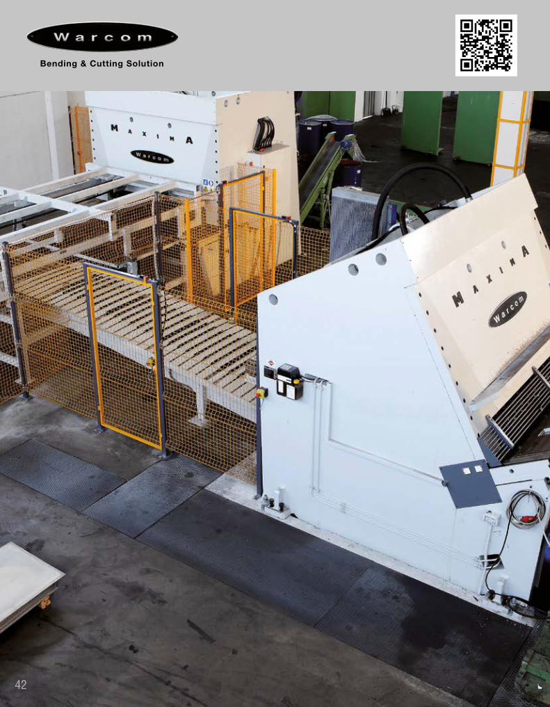
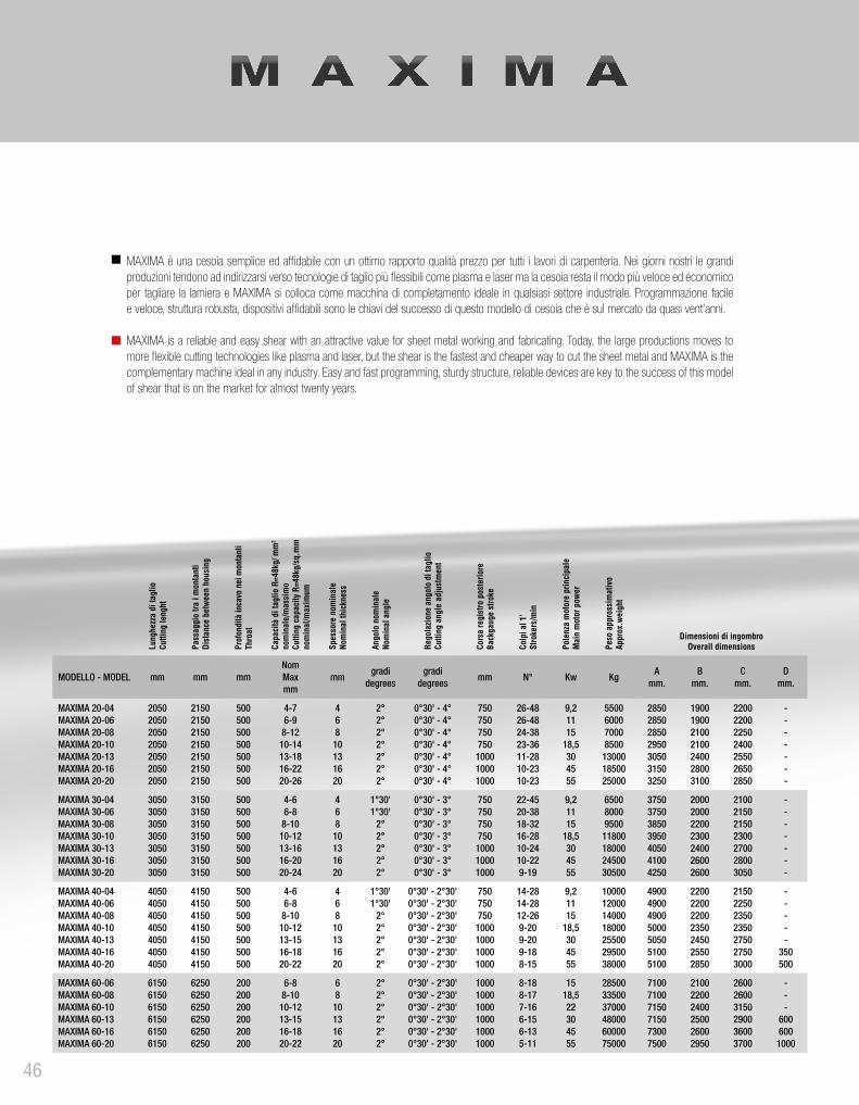
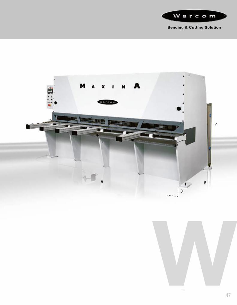
MAXIMA è una cesoia semplice ed affidabile con un ottimo rapporto qualità prezzo per tutti i lavori di carpenteria. Nei giorni nostri le grandi produzioni tendono ad indirizzarsi verso tecnologie di taglio più flessibili come plasma e laser ma la cesoia resta il modo più veloce ed economico per tagliare la lamiera e MAXIMA si colloca come macchina di completamento ideale in qualsiasi settore industriale. Programmazione facile e veloce, struttura robusta, dispositivi affidabili sono le chiavi del successo di questo modello di cesoia che è sul mercato da quasi vent’anni.
MAXIMA is a reliable and easy shear with an attractive value for sheet metal working and fabricating. Today, the large productions moves to more flexible cutting technologies like plasma and laser, but the shear is the fastest and cheaper way to cut the sheet metal and MAXIMA is the complementary machine ideal in any industry. Easy and fast programming, sturdy structure, reliable devices are key to the success of this model of shear that is on the market for almost twenty years.
Lung
hezz
a di
tagl
ioCu
tting
leng
ht
Pass
aggi
o tra
i m
onta
nti
Dist
ance
bet
ween
hou
sing
Prof
ondi
tà in
cavo
nei
mon
tant
iTh
roat
Capa
cità
di t
aglio
R=4
8kg/
mm
2 no
min
ale/
mas
sim
oCu
tting
cap
acity
R=4
8kg/
sq.m
mno
min
al/m
axim
um
Spes
sore
nom
inal
eNo
min
al th
ickn
ess
Ango
lo n
omin
ale
Nom
inal
ang
le
Rego
lazio
ne a
ngol
o di
tagl
ioCu
tting
ang
le a
djus
tmen
t
Cors
a re
gist
ro p
oste
riore
Back
gaug
e st
roke
Colp
i al 1
’St
roke
rs/m
in
Pote
nza
mot
ore
prin
cipa
leM
ain
mot
or p
ower
Peso
app
ross
imat
ivo
Appr
ox.w
eigh
t
Dimensioni di ingombroOverall dimensions
MODELLO - MODEL mm mm mmNomMaxmm
mmgradi
degreesgradi
degreesmm N° Kw Kg
Amm.
Bmm.
Cmm.
Dmm.
MAXIMA 20-04MAXIMA 20-06MAXIMA 20-08MAXIMA 20-10MAXIMA 20-13MAXIMA 20-16MAXIMA 20-20
2050205020502050205020502050
2150215021502150215021502150
500500500500500500500
4-76-98-1210-1413-1816-2220-26
46810131620
2°2°2°2°2°2°2°
0°30' - 4°0°30' - 4°0°30' - 4°0°30' - 4°0°30' - 4°0°30' - 4°0°30' - 4°
750750750750
100010001000
26-4826-4824-3823-3611-2810-2310-23
9,21115
18,5304555
5500600070008500
130001850025000
2850285028502950305031503250
1900190021002100240028003100
2200220022502400255026502850
-------
MAXIMA 30-04MAXIMA 30-06MAXIMA 30-08MAXIMA 30-10MAXIMA 30-13MAXIMA 30-16MAXIMA 30-20
3050305030503050305030503050
3150315031503150315031503150
500500500500500500500
4-66-88-1010-1213-1616-2020-24
46810131620
1°30'1°30'
2°2°2°2°2°
0°30' - 3°0°30' - 3°0°30' - 3°0°30' - 3°0°30' - 3°0°30' - 3°0°30' - 3°
750750750750
100010001000
22-4520-3818-3216-2810-2410-229-19
9,21115
18,5304555
650080009500
11800180002450030500
3750375038503950405041004250
2000200022002300240026002600
2100215021502300270028003050
-------
MAXIMA 40-04MAXIMA 40-06MAXIMA 40-08MAXIMA 40-10MAXIMA 40-13MAXIMA 40-16MAXIMA 40-20
4050405040504050405040504050
4150415041504150415041504150
500500500500500500500
4-66-88-1010-1213-1516-1820-22
46810131620
1°30'1°30'
2°2°2°2°2°
0°30' - 2°30'0°30' - 2°30'0°30' - 2°30'0°30' - 2°30'0°30' - 2°30'0°30' - 2°30'0°30' - 2°30'
750750750
1000100010001000
14-2814-2812-269-209-209-188-15
9,21115
18,5304555
10000120001400018000255002950038000
4900490049005000505051005100
2200220022002350245025502850
2150225023502350275027503000
-----
350500
MAXIMA 60-06MAXIMA 60-08MAXIMA 60-10MAXIMA 60-13MAXIMA 60-16MAXIMA 60-20
615061506150615061506150
625062506250625062506250
200200200200200200
6-88-1010-1213-1516-1820-22
6810131620
2°2°2°2°2°2°
0°30' - 2°30'0°30' - 2°30'0°30' - 2°30'0°30' - 2°30'0°30' - 2°30'0°30' - 2°30'
100010001000100010001000
8-188-177-166-156-135-11
1518,522304555
285003350037000480006000075000
710071007150715073007500
210022002400250026002950
260026003150290036003700
---
600600
1000
47
48
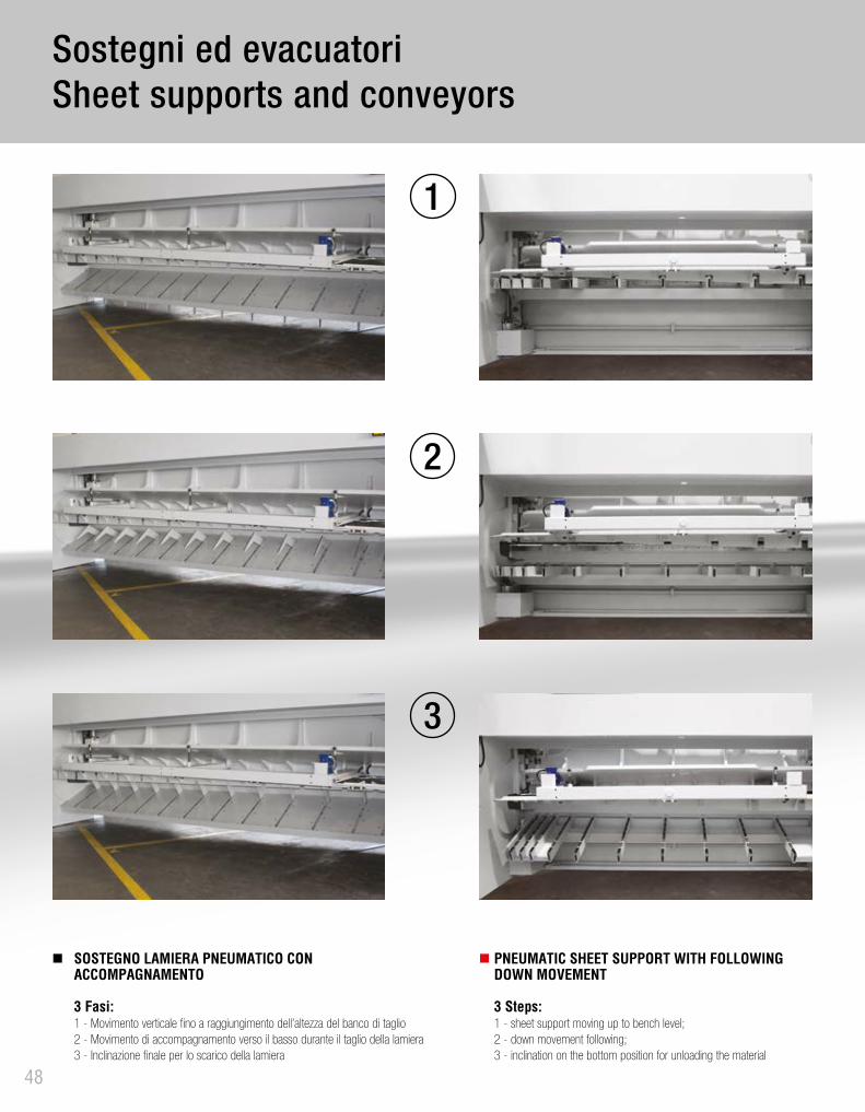
Sostegni ed evacuatoriSheet supports and conveyors
PNEUMATIC SHEET SUPPORT WITH FOLLOWING DOWN MOVEMENT 3 Steps: 1 - sheet support moving up to bench level;2 - down movement following;3 - inclination on the bottom position for unloading the material
SOSTEGNO LAMIERA PNEUMATICO CON ACCOMPAGNAMENTO 3 Fasi: 1 - Movimento verticale fino a raggiungimento dell’altezza del banco di taglio2 - Movimento di accompagnamento verso il basso durante il taglio della lamiera3 - Inclinazione finale per lo scarico della lamiera
3
2
1

49
Convogliatore evacuatore con selettori sfridi.Belt conveyor with trim cut selector.
Paramani ribaltabile.Movable swing-up front safety guard.
Paramani a greca.Shaped front safety guard.
AccessoriAccessories

50
Programmatore CNC scorrevole.Sliding CNC control.
Unità quadro comandi con controllo numerico.Control panel with numerical control.
Controlli CNCCNC control

Warcom service department stands for competence and promptness. A technical service team is always available to customers for assistance and training.Warcom supports its customers with a personalized assistance service throughout all the machine life.For our customers there are various training courses aimed at qualifying the operators in order to optimize the knowledge on how to use the machine technology.A warehouse with quality control and material storage ensures a fast delivery of spare parts.
AssistenzaService
Ufficio progettazioneDesign department
51
Il reparto assistenza Warcom, è sinonimo di competenza e celerità. Un team di tecnici è sempre a disposizione della clientela per collaudi, assistenze e corsi di aggiornamento.Warcom supporta la propria clientela con un servizio di assistenza personalizzato durante l’intera vita delle macchine.A disposizione della clientela ci sono vari corsi di formazione finalizzati a qualificare gli operatori delle macchine in modo da poterne sfruttare al massimo le potenzialità tecnologiche.Un magazzino con controllo qualità e deposito materiale è pronto a garantire una veloce consegna della ricambistica.
La progettazione è fondata sulla filosofia del creare sempre la soluzione per ottenere i migliori risultati.Sistemi di informatica all’avanguardia supportano i nostri ingegneri qualificati di massimo livello.L’ufficio tecnico è disponibile anche per sviluppare studi di fattibilità e attrezzaggio macchine; prima di una decisione d’acquisto, Warcom fornisce informazioni complete ed esaustive in modo da ottimizzare l’esigenza del cliente con le prestazioni e le caratteristiche della macchina.
The design is based on the philosophy of creating the right solution to get the best results. Advanced computer systems support our qualified engineers. The technical department is available to develop feasibility studies and tooling machines; before a purchase decision, Warcom provides information in order to optimize the customer’s request with the performance and characteristics of the machine.
52 I dati contenuti nel presente catalogo sono indicativi. In considerazione del nostro continuo aggiornamento tecnologico potranno variare senza preavviso alcuno.
The data given in the present catalogue are indicative. In consideration of our always improving technology, characteristics are given merely on information basis and can be modified at any time without prior notice.
COLLECTION CUTTINGCOLLEZIONE TAGLIO
COLLECTION BENDINGCOLLEZIONE PIEGATURA
COLLECTION LASERCOLLEZIONE LASER


Ed. 0
7/16