collision resolution mac protocols for wireless ad hoc networks
TRANSCRIPT

Communications and Network, 2013, 5, 16-33 http://dx.doi.org/10.4236/cn.2013.51003 Published Online February 2013 (http://www.scirp.org/journal/cn)
Collision Resolution MAC Protocols for Wireless Ad Hoc Networks*
Xinhua Yang, Tracy Camp Tracy Camp Department of Electrical Engineering & Computer Science, Colorado School of Mines, Golden, USA
Email: [email protected], [email protected]
Received October 12, 2012; revised November 15, 2012; accepted December 18, 2012
ABSTRACT
In wireless ad hoc networks, nodes cooperatively form a network without any infrastructure such as a BS/AP (base sta-tion or access point). The widely-used contention-based MAC protocol, IEEE 802.11b, is inefficient in multi-hop net-works due to the hidden and exposed terminal problems. The most popular schedule-based MAC protocol, TDMA (time division multiple access), is difficult to implement in an ad hoc network due to the lack of infrastructure. The con-tribution of this paper is to provide the community novel and efficient MAC (medium access control) protocols (i.e., a collision resolution protocol) for a wireless ad hoc network without a centralized infrastructure. We propose two new MAC protocols (one distributed algorithm and one cluster-based algorithm) that use a collision resolution scheme for a network with a single BS/AP. We first compare the performance of our distributed algorithm with our cluster-based algorithm. Then, we compare our algorithm that performs better (i.e., our cluster-based algorithm) to TDMA in a two- hop network. The simulation results illustrate that our cluster-based algorithm provides higher throughput and lower delay than TDMA in a two-hop network. Keywords: Ad Hoc Networks; Cluster-Based Algorithms; Collision Resolution Scheme; MAC Protocols
1. Introduction
A wireless ad hoc network is a network of wireless de-vices, such as laptops and PDAs (personal digital assis-tants). These devices cooperatively form a network without any infrastructure such as a BS/AP. A wireless ad hoc network may operate in isolation or connect to the Internet. Every node in the network is a router that main-tains routing information among its neighbors. A connec-tion in a wireless ad hoc network may traverse multiple nodes, thus defining a multi-hop ad hoc network. Wire-less ad hoc networks can be deployed in many scenarios where infrastructures are unavailable. For example, in disaster recovery, where the communication infrastruc-ture is destroyed, a wireless ad hoc network can be in-stalled quickly to enable the communication. Wireless ad hoc networks can also be used in military missions and commercial environments. Due to their flexibility, wire-less ad hoc networks will play an important role in sce-narios where an infrastructure is either non-existant or destroyed.
A good MAC protocol is critical in a wireless ad hoc network to ensure collision free transmissions. Tradi-tional MAC protocols can be classified into two catego-ries: contention-based protocols and schedule based pro-tocols. A widely-used contention-based MAC protocol is
IEEE 802.11b; however, it is inefficient in multi-hop networks due to the hidden and exposed terminal prob-lems. A well-known schedule-based MAC protocol is TDMA. In TDMA, nodes can only transmit at time slots allocated to them. Since each time slot is allocated to one node, the transmission is collision free.
Traditional MAC protocols focus on how to avoid col-lisions in the network. In this paper, we propose two new approaches that incorporate a collision resolution scheme (ALLIANCES) [1]. The advantages of ALLIANCES are: 1) the reuse of collided packets saves time and energy and 2) no slot assignment scheduling is needed. Accord-ing to ALLIANCES in [1], if a collision of degree occurs, the
K1K subsequent time slots are reserved by
the BS/AP for retransmissions. During each of the 1K subsequent time slots, the BS/AP selects neighboring nodes in the network (i.e., relay nodes) to retransmit the collided packets. Thus, the BS/AP receives a total of K linear mixtures of collided packets. Then, assuming chan- nel knowledge, the BS/AP formulates a multiple-input multiple-output (MIMO) identification problem, the so-lution of which yields the collided packets. See [1] for more details.
In [1], all nodes implementing ALLIANCES are asso-ciated with a single BS/AP. The contribution of our work, described in this paper, is to propose a collision resolu-tion scheme when there is no central BS/AP in the net-*This work has been supported by NSF under grant CNS-0905513.
Copyright © 2013 SciRes. CN

X. H. YANG, T. CAMP 17
work. In other words, we propose a novel MAC protocol (i.e., a collision resolution protocol) for a wireless net-work with no centralized BS/AP. The challenges of our efforts are to decide which nodes are used to resolve a collision and which nodes are used to relay a collision heard. In Section 2 and Section 3, we propose two ap-proaches to deal with these issues. In Section 4 and Sec-tion 5, we present our simulation configuration and simulation results, respectively, to evaluate the perform-ance of our two protocols and to compare our protocol that performs the best to TDMA. We present conclusions in Section 6.
2. Idea 1: A Distributed Algorithm
The basic idea of the distributed algorithm follows: if a collision occurs, all pseudo BSs begin collision resolu-tion. We define a pseudo BS as a node that hears the col-lision and is a destination for one of the packets involved in the collision. In order to determine whether a node is the destination of a packet mixture, orthogonal IDs are used within each packet’s header. For example, a re-ceived orthogonal ID of 01100 in the destination field means that node 2 and node 3 need to act as pseudo BSs. To avoid long IDs in a large ad hoc network, we use lo-calized orthogonal IDs that allow ID reuse over well- separated areas. If orthogonal IDs are not available, our proposed distributed algorithm is still possible via a blind source separation problem. Such an approach, however, is more complex and not considered further. In other words, we assume localized orthogonal IDs are available for the network nodes.
Suppose a collision occurs among four nodes within the network as shown in Figure 1. In this figure, the four nodes transmitting are nodes 7, 10, 12, and 18, and the four destination nodes for these four transmissions are 8, 16, 14, and 13, respectively. Destination nodes 8 and 14 are in non-overlapping regions of the transmission areas; therefore, nodes 8 and 14 will properly receive the origi-nal packet sent. Destination node 16, however, will re-ceive a collision (a mixture of two packets) and will be-gin collision resolution. Because destination node 16 only cares about one of the two packets within the packet mixture received, it will factor out the other source packet during its collision resolution. Similarly, destina-tion node 13 will receive a mixture of two packets, and will begin collision resolution to factor out the source packet destined for node 14. To simplify the system, we make the following assumptions: The network is a slotted multiple access system. The
nodes transmit in the same static channel and each node can receive control packets from neighboring nodes on a control channel.
Each node is equipped with only one omni-direc- tional antenna that operates in a half-duplex mode.
Thus, a node cannot transmit and receive simultane-ously on the traffic channel.
Each transmitted packet has the same length and re-quires one time slot for transmission.
2.1. Collision Resolution Mode
When a collision occurs, nodes that hear the collision are able to determine the source node IDs and destination node IDs contained in the mixture using orthogonal IDs. In some cases, the destination nodes of a mixture are within the transmission range of each other; thus, if these nodes start collision resolution at the same time, a new collision might occur on the control channel. In order to reduce collisions on the control channel, pseudo BSs do not start collision resolution right after the collision oc-curs. Instead, pseudo BSs postpone collision resolution for some random number of slots; specifically, nodes with smaller IDs start collision resolution earlier than nodes with larger IDs.
When a node begins collision resolution, it sends a control packet on a control channel to all nodes within its transmission range. This packet indicates the beginning of a cooperative transmission epoch (CTE); the node will continue sending a control packet (each of which chooses a relay node) until the node has enough information to resolve the collision. Even though the pseudo BSs start collision resolution at a random time, it is still possible that some node is within transmission range of two nodes trying to resolve a collision at the same time. In this case, both nodes will send a control packet that chooses a relay node to transmit. For example, in Figure 2, node 3 will receive a mixture of the control packets from nodes 13 and 16. If a node receives a control packet that indicates at least one node within range has entered collision reso-lution mode, then the node will not transmit new packets.
2.2. Relay Node Selection
In ALLIANCES [1], the CTE consists of ˆ 1K slots, with K̂ K
n
. During slot , where , a relay node transmits the signal mixture that it received during the -th slot (the collision slot). In ALLIANCES, one option for the selection of each relay node is the RRS (random relay selection) scheme. In this method, select-ing the relay nodes is deterministic and no control over-head is needed to determine the order in which the relays will transmit. In a large scale multi-hop network, not all of the nodes in the network are within range of each other. Thus, the RRS scheme needs to be modified to be used in our distributed algorithm.
n k ˆk K 1 1
We assume each node maintains a neighbor list; this neighbor list could be implemented in many ways (e.g., nodes periodically send a HELLO message). While neighbor knowledge can be costly to maintain, many
Copyright © 2013 SciRes. CN

X. H. YANG, T. CAMP
Copyright © 2013 SciRes. CN
18
Figure 1. An example collision in a wireless ad hoc network. In this example, the transmitting nodes are nodes 7, 10, 12, and 18. The destination nodes for these four transmissions are nodes 8, 16, 14, and 13, respectively.
Figure 2. Collision resolution of the distributed algorithm. Two destination nodes, 13 and 16, enter collision resolution and transmit a control packet to all nodes within range. All nodes within range remain quiet or act as relays.

X. H. YANG, T. CAMP 19
protocols at different layers require this knowledge. We assume that this knowledge is available from another protocol or from listening on the channel. With an accu-rate neighbor list, a pseudo BS can choose relay nodes from the neighbor list via RRS [1] or LRS (location relay selection) [2] if location information on neighbors is also available. Thus, with an accurate neighbor list, the pseu- do BS can send a control packet that chooses a relay node to transmit.
2.3. Pseudocode of Our Distributed Algorithm
The pseudocode of our distributed algorithm is given in Figure 3. At the beginning of each slot, if no control packet from neighboring nodes has been received, the nodes that have packets in the queue transmit. Con-versely, the nodes that have no packets in the queue keep silent. If a node receives a packet at some slot, then the node considers the source and destination node IDs for the received packet. If the node heard a collision and is the first node in the destination nodes list (DNL, ordered by node IDs), then it sets the resolution start slot (RSS) to ( n is the collision slot). If the node is a desti-nation node but not the first node in the DNL, it sets RSS to , where is the index of the node in the DNL, is the number of nodes involved in the collision, and is a random number between 0 and
. It is possible that two nodes within transmis-sion range of each other hear a collision of the same de-gree (i.e., the same ) at the same slot (i.e., the same
) and have the same index in the DNL (i.e., the same ). Thus, a random number is used to avoid having
the two nodes start to resolve collisions at the same time.
1n
21
1K R KR
K
1 *n i i
K
ni R
Suppose a node hears a collision of degree . To re-cover all collided packets, the node needs
K1K more
slots for the relay nodes to either transmit the signals saved in their buffer (for non-source nodes) or retransmit the original packet (for source nodes). If RSS of a desti-nation node equals ( c is the current slot number), the node sends a control packet to neighboring nodes to indicate the start of its CTE; this packet is sent at the end of slot . At the end of the node’s CTE, the node will have collected enough packets to resolve the collision (assuming all packets received are useful) via the Zero Forcing (ZF) decoder [3] or the Maximum Likelihood (ML) decoder [3].
1c
c
3. Idea 2: A Cluster-Based Algorithm
Our second idea to control medium access in wireless ad hoc networks is a cluster-based algorithm. In this algo-rithm, nodes are grouped into clusters according to some rules. Each cluster head (CH) is responsible to allocate time slots to nodes in its cluster and two adjacent clusters should not interfere with each other. In this algorithm, we
have two types of communication: inter-cluster commu-nication and intra-cluster communication. We define inter- cluster communication as communication between dif-ferent clusters and intra-cluster communication as com-munication within one cluster.
Cluster-based medium access algorithms can be di-vided into two categories: topology-dependent algori- thms [4,5] and topology-transparent algorithms [6,7]. In topology-dependent algorithms [4,5], nodes are grouped into clusters according to the current topology. Each CH assigns time slots to nodes in its cluster whenever the topology changes in order to achieve intra-cluster com-munication. In a wireless ad hoc network, nodes may move quickly, which results in a rapidly changing topol-ogy. A rapidly changing topology makes the assignment of time slots very difficult for a topology-dependent al-gorithm. Further, the frequent assignment of time slots generates significant overhead and, therefore, greatly decreases the network’s throughput.
In order to overcome the inefficiency of topology-de- pendent algorithms, a number of topology-transparent methods have been proposed (e.g., [6,7]). In topology- transparent algorithms, nodes are grouped into clusters according to their locations. Clusters in a network do not overlap and each cluster contains nodes in a specific area. TBMAC (time bounded medium access control) [6] and STDMA (space-time division multiple access) [7] are two topology-transparent algorithms. In TBMAC, adja-cent clusters use different frequencies or CDMA (code division multiple access) codes to achieve intra-cluster communication. Nodes in each cluster contend for time slots in the contention period and transmit in the conten-tion free period. Nodes that need to communicate be-tween clusters must use the reserved slots for inter-clus- ter communication. In STDMA, each cluster uses the same frequency for intra-cluster communication and time slots are allocated to clusters in turn; however, two clus-ters that are far away can transmit at the same time.
Our cluster-based algorithm is a topology-transparent algorithm. To reduce the inter-cluster interference, adja-cent clusters can either use different frequencies (as done in TBMAC) or transmit in turn using the same frequency (as done in STDMA). The algorithm using different fre-quencies works as follows. Each cluster has two CHs, one CH for intra-cluster communication and one CH for inter-cluster communication. The CHs for intra-cluster communication transmit on different frequency channels to avoid interference and the CHs for inter-cluster com-munication transmit on the same frequency channel using any traditional MAC protocol, such as CSMA (carrier sense multiple access). Having two CHs allows intra- cluster communication and inter-cluster communication to operate in parallel.
When compared to the approach that has clusters
Copyright © 2013 SciRes. CN

X. H. YANG, T. CAMP 20
Figure 3. Our distributed algorithm to create a multi-hop ALLIANCES network. DNL is the destination nodes list (ordered by node IDs), SNL is the source nodes list, i is the index of a destination node in the DNL, and RSS (resolution start slot) is the slot number at which a destination node starts to resolve a collision. If a node receives “begin CTE bit” on the control channel, then the node sets CTE state; if a node receives “end CTE bit” on the control channel, then the node sets non-CTE state. transmit in turn on the same frequency, using different frequencies has smaller delay; however, it increases the cost of nodes greatly. Depending on the application, we can either use different frequencies to lower the delay or the same frequency to lower the cost. Since the approach using different frequencies has higher cost, our algorithm allows clusters to transmit in turn on the same frequency
channel (as done in STDMA). To simplify the system, we make the same three assumptions as in the distributed algorithm (see Section 2) and the following three new assumptions: Each node can hear from its CH on a control channel. Each cluster has the same area; within a cluster, any
node can reach any other node within two hops (e.g.,
Copyright © 2013 SciRes. CN
X. H. YANG, T. CAMP 21
via the CH). Each node knows its own location and each CH
knows the locations of all nodes in its cluster.
3.1. Collision Resolution Mode
In non-CTE mode, neighboring CHs transmit packets to the CH of cluster A during cluster A’s transmission time. Nodes in cluster A can also transmit to other nodes in cluster A during cluster A’s transmission time. A node transmits a packet to a destination directly if the destina-tion node is in the node’s neighbor list. (An approach to maintain a neighbor list is discussed in Section 2). Oth-erwise, the node transmits the packet to the CH and the CH forwards the packet to the destination. At the end of each time slot, the CH checks the orthogonal IDs re-ceived and determines if a collision occurred. If a colli-sion occurred, the CH can determine the number of des-tination nodes that heard the collision using known loca-tion information for the source nodes and destination nodes. If the collision only happened at one destination, the CH assigns the destination node to resolve the colli-sion. If the collision happened at more than one destina-tion, the CH attempts to resolve the collision. If the colli-sion is resolved, the CH then forwards the resolved packets to either the destination nodes directly (when the packets are destined to nodes inside its cluster) or its neighboring CH (when the packets are destined to nodes in another cluster). Packets sent to nodes within the clus-ter are transmitted immediately; packets sent to neigh- boring CHs are transmitted during the neighboring clus-ter’s time frame.
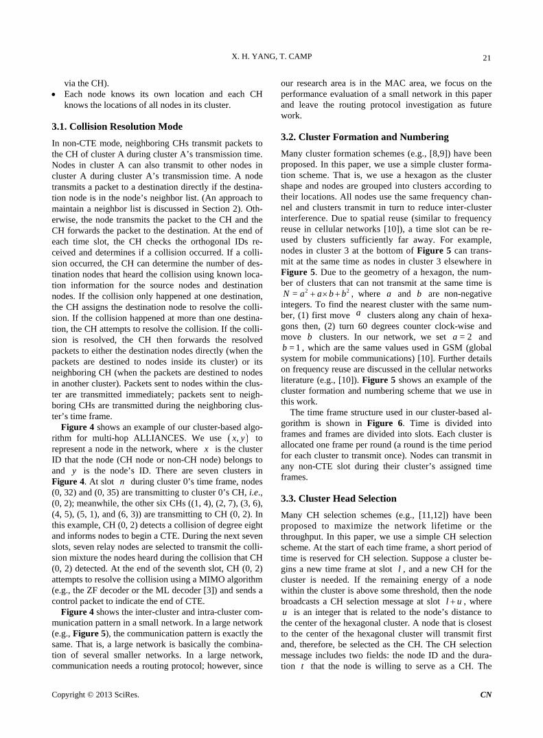
Figure 4 shows an example of our cluster-based algo-rithm for multi-hop ALLIANCES. We use ,x y to represent a node in the network, where x is the cluster ID that the node (CH node or non-CH node) belongs to and is the node’s ID. There are seven clusters in Figure 4. At slot during cluster 0’s time frame, nodes (0, 32) and (0, 35) are transmitting to cluster 0’s CH, i.e., (0, 2); meanwhile, the other six CHs ((1, 4), (2, 7), (3, 6), (4, 5), (5, 1), and (6, 3)) are transmitting to CH (0, 2). In this example, CH (0, 2) detects a collision of degree eight and informs nodes to begin a CTE. During the next seven slots, seven relay nodes are selected to transmit the colli-sion mixture the nodes heard during the collision that CH (0, 2) detected. At the end of the seventh slot, CH (0, 2) attempts to resolve the collision using a MIMO algorithm (e.g., the ZF decoder or the ML decoder [3]) and sends a control packet to indicate the end of CTE.
yn
Figure 4 shows the inter-cluster and intra-cluster com-munication pattern in a small network. In a large network (e.g., Figure 5), the communication pattern is exactly the same. That is, a large network is basically the combina-tion of several smaller networks. In a large network, communication needs a routing protocol; however, since
our research area is in the MAC area, we focus on the performance evaluation of a small network in this paper and leave the routing protocol investigation as future work.
3.2. Cluster Formation and Numbering
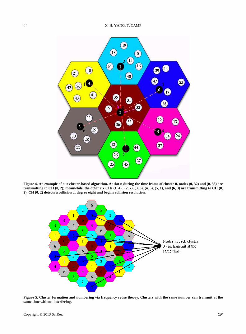
Many cluster formation schemes (e.g., [8,9]) have been proposed. In this paper, we use a simple cluster forma- tion scheme. That is, we use a hexagon as the cluster shape and nodes are grouped into clusters according to their locations. All nodes use the same frequency chan- nel and clusters transmit in turn to reduce inter-cluster interference. Due to spatial reuse (similar to frequency reuse in cellular networks [10]), a time slot can be re- used by clusters sufficiently far away. For example, nodes in cluster 3 at the bottom of Figure 5 can trans- mit at the same time as nodes in cluster 3 elsewhere in Figure 5. Due to the geometry of a hexagon, the num- ber of clusters that can not transmit at the same time is
2 2=N a a b b
b= 1b
, where and b are non-negative integers. To find the nearest cluster with the same num-ber, (1) first move clusters along any chain of hexa-gons then, (2) turn 60 degrees counter clock-wise and move clusters. In our network, we set and
, which are the same values used in GSM (global system for mobile communications) [10]. Further details on frequency reuse are discussed in the cellular networks literature (e.g., [10]). Figure 5 shows an example of the cluster formation and numbering scheme that we use in this work.
a
a
= 2a
The time frame structure used in our cluster-based al-gorithm is shown in Figure 6. Time is divided into frames and frames are divided into slots. Each cluster is allocated one frame per round (a round is the time period for each cluster to transmit once). Nodes can transmit in any non-CTE slot during their cluster’s assigned time frames.
3.3. Cluster Head Selection
Many CH selection schemes (e.g., [11,12]) have been proposed to maximize the network lifetime or the throughput. In this paper, we use a simple CH selection scheme. At the start of each time frame, a short period of time is reserved for CH selection. Suppose a cluster be-gins a new time frame at slot , and a new CH for the cluster is needed. If the remaining energy of a node within the cluster is above some threshold, then the node broadcasts a CH selection message at slot
l
l u , where is an integer that is related to the node’s distance to
the center of the hexagonal cluster. A node that is closest to the center of the hexagonal cluster will transmit first and, therefore, be selected as the CH. The CH selection message includes two fields: the node ID and the dura-tion that the node is willing to serve as a CH. The
u
t
Copyright © 2013 SciRes. CN
X. H. YANG, T. CAMP
Copyright © 2013 SciRes. CN
22
Figure 4. An example of our cluster-based algorithm. At slot n during the time frame of cluster 0, nodes (0, 32) and (0, 35) are transmitting to CH (0, 2); meanwhile, the other six CHs (1, 4) , (2, 7), (3, 6), (4, 5), (5, 1), and (6, 3) are transmitting to CH (0, 2). CH (0, 2) detects a collision of degree eight and begins collision resolution.
Figure 5. Cluster formation and numbering via frequency reuse theory. Clusters with the same number can transmit at the same time without interfering.

X. H. YANG, T. CAMP 23
Figure 6. The time frame structure used in our cluster-based algorithm. Time is divided into frames and frames are divided into slots. Each cluster is allocated one frame per round. A node within a cluster can transmit in any non-CTE slot during its cluster’s time frame. duration is at least the length of one round.
3.4. Variable Transmission Ranges
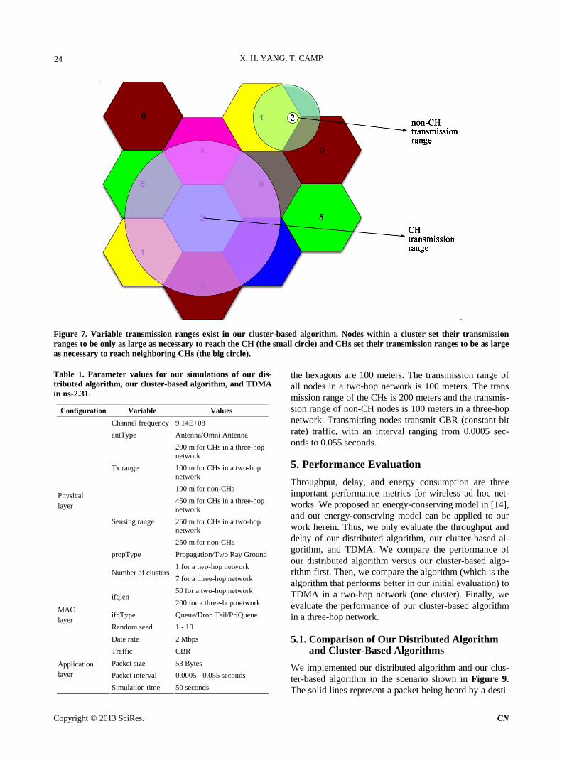
In the example in Figure 4, the nodes within a cluster only need to reach their CH, and the distance to the CH is about the radius of a hexagon. A CH, however, needs to reach its neighboring CHs. Thus, variable transmission ranges are used in our work. The transmission range of a non-CH node is the radius of the hexagon (see the small circle around node (1, 2) in Figure 7). The transmission range of a CH is about two times the radius of the hexa-gon (see the big circle around the center of cluster 2 in Figure 7). Since a multi-hop transmission requires a routing protocol and our work is on the MAC layer, we focus our evaluation on a two-hop network. In a two-hop network, there is only one CH; thus, the transmission range of the CH is the same as that of non-CH nodes.
3.5. Pseudocode of Our Cluster-Based Algorithm
The pseudocode of our cluster-based algorithm is illus-trated in Figure 8. Each node in cluster A (during cluster A’s time frames) works as follows. (A represents any integer between zero and six.) At the beginning of each slot, if cluster A’s nodes have not received any control packet from A’s CH, the nodes with packets in the queue transmit. Conversely, the nodes that have no packets in the queue remain silent.
If a collision occurs, the CH calculates the source and destination node IDs sent in the collision slot. Suppose K nodes send a packet to create the collision. If the K nodes were sent to the same destination node, the CH assigns the destination node to resolve the collision. If the destination nodes are not the same, the CH needs K
1K F slots (where F is the number of destination nodes in the cluster and F K ) to handle the collision. During the first 1K slots, relay nodes either transmit the signal saved in their buffer (for non-source nodes) or
retransmit the original packet (for source nodes). After 1K slots, the CH has collected enough packets to re-
solve the collision (assuming all packets received are useful) via the ZF decoder [3] or the ML decoder [3]. During the following F slots, the CH forwards the re-solved packets to the destination nodes within the cluster.
Each non-CH node in cluster B remains silent during the time frame for cluster A’s transmissions; B represents any integer between zero and six such that A B . If the CH of cluster B has packets for cluster A, then the CH of cluster B transmits the packets to the CH of cluster A during non-CTE slots in cluster A’s time frame. For sim-plicity, we assume the CH does not need to transmit its own packets in Figure 8. (A CH can not transmit during a non-CTE slot since it must listen for potential colli-sions.) A CH with packets to send can either 1) set the CTE bit and transmit immediately (if a collision has not happened recently) or 2) increase F and transmit after a collision has been resolved.
4. Simulation Configuration
The Network Simulator (NS-2) [13] is a discrete event simulator for communication networks and is part of the VINT project. We choose NS-2 (version 2.31) to simu-late our distributed algorithm, our cluster-based algo-rithm, and TDMA. The configuration of our NS-2 im-plementation consists of three parts: physical layer con-figuration, MAC layer configuration, and application layer configuration. The parameter values for our NS-2 implementation of our distributed algorithm, our clus-ter-based algorithm, and TDMA are listed in Table 1.
The propagation model is the Two Ray Ground model; the Two Ray Ground model considers both the direct path and the ground reflection path in a packet’s propa-gation. We model the channel coefficients as zero-mean Gaussian random variables with variance 2
a , which are independent of path and remain constant over successive time slots (the collision slot and the CTE). The radii of
Copyright © 2013 SciRes. CN
X. H. YANG, T. CAMP 24
Figure 7. Variable transmission ranges exist in our cluster-based algorithm. Nodes within a cluster set their transmission ranges to be only as large as necessary to reach the CH (the small circle) and CHs set their transmission ranges to be as large as necessary to reach neighboring CHs (the big circle). Table 1. Parameter values for our simulations of our dis-tributed algorithm, our cluster-based algorithm, and TDMA in ns-2.31.
Configuration Variable Values
Channel frequency 9.14E+08
antType Antenna/Omni Antenna
200 m for CHs in a three-hop network
100 m for CHs in a two-hop network
Tx range
100 m for non-CHs
450 m for CHs in a three-hop network
250 m for CHs in a two-hop network
Sensing range
250 m for non-CHs
propType Propagation/Two Ray Ground
1 for a two-hop network
Physical layer
Number of clusters7 for a three-hop network
50 for a two-hop network ifqlen
200 for a three-hop network
ifqType Queue/Drop Tail/PriQueue
Random seed 1 - 10
MAC layer
Date rate 2 Mbps
Traffic CBR
Packet size 53 Bytes
Packet interval 0.0005 - 0.055 seconds
Application layer
Simulation time 50 seconds
the hexagons are 100 meters. The transmission range of all nodes in a two-hop network is 100 meters. The trans mission range of the CHs is 200 meters and the transmis-sion range of non-CH nodes is 100 meters in a three-hop network. Transmitting nodes transmit CBR (constant bit rate) traffic, with an interval ranging from 0.0005 sec-onds to 0.055 seconds.
5. Performance Evaluation
Throughput, delay, and energy consumption are three important performance metrics for wireless ad hoc net-works. We proposed an energy-conserving model in [14], and our energy-conserving model can be applied to our work herein. Thus, we only evaluate the throughput and delay of our distributed algorithm, our cluster-based al-gorithm, and TDMA. We compare the performance of our distributed algorithm versus our cluster-based algo-rithm first. Then, we compare the algorithm (which is the algorithm that performs better in our initial evaluation) to TDMA in a two-hop network (one cluster). Finally, we evaluate the performance of our cluster-based algorithm in a three-hop network.
5.1. Comparison of Our Distributed Algorithm and Cluster-Based Algorithms
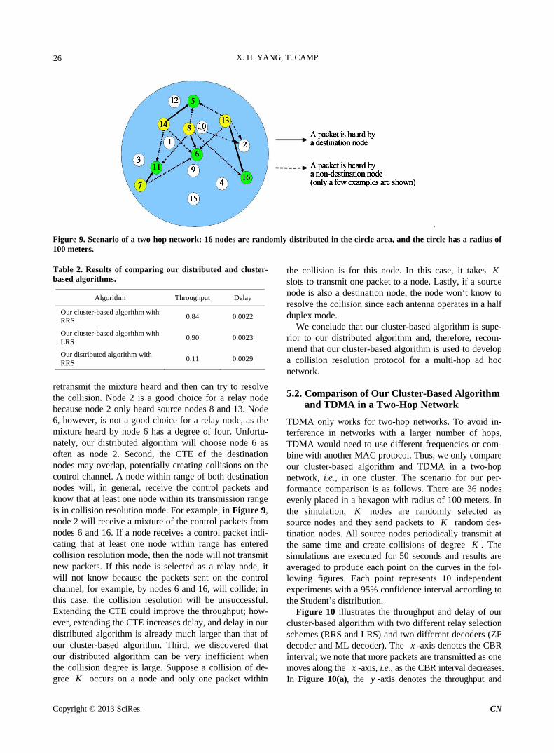
We implemented our distributed algorithm and our clus-ter-based algorithm in the scenario shown in Figure 9. The solid lines represent a packet being heard by a desti-
Copyright © 2013 SciRes. CN

X. H. YANG, T. CAMP 25
Figure 8. Our cluster-based algorithm to create a multi-hop ALLIANCES network. For simplicity, we assume the CH does not need to transmit its own packets. F is the number of destination nodes within cluster A. A and B represent two different integers that are between zero and six. If a node receives “begin CTE bit” on the control channel, then the node sets CTE state; if a node receives “end CTE bit” on the control channel, then the node sets non-CTE state. nation node and the dashed lines represent a packet being heard by a non-destination node. The network is a two- hop network; in other words, every node can reach every other node in two hops. There are 16 nodes in the net-work and four nodes (nodes 7, 8, 13 and 14) transmit CBR traffic every 0.01 seconds at the same time to create collisions. At destination nodes (nodes 5, 6, 11, and 16), the collision degrees are 3, 4, 3, and 2, respectively. We executed our simulation for 50 seconds. Both our distrib-uted and cluster-based algorithms use the ZF decoder [3]
to resolve collisions. The simulation results are shown in Table 2. As shown, the performance of our distributed algorithm is poor; thus, we do not provide further simu-lation results on this algorithm.
The throughput of our distributed algorithm is very low due to four main reasons. First, the mixture received by a destination node and the mixture received by a relay node may contain a different number of source packets. For example, in Figure 9, node 16 detects a collision of order two. Thus, node 16 only requires one relay node to
Copyright © 2013 SciRes. CN
X. H. YANG, T. CAMP 26
Figure 9. Scenario of a two-hop network: 16 nodes are randomly distributed in the circle area, and the circle has a radius of 100 meters. Table 2. Results of comparing our distributed and cluster- based algorithms.
Algorithm Throughput Delay
Our cluster-based algorithm with RRS
0.84 0.0022
Our cluster-based algorithm with LRS
0.90 0.0023
Our distributed algorithm with RRS
0.11 0.0029
retransmit the mixture heard and then can try to resolve the collision. Node 2 is a good choice for a relay node because node 2 only heard source nodes 8 and 13. Node 6, however, is not a good choice for a relay node, as the mixture heard by node 6 has a degree of four. Unfortu-nately, our distributed algorithm will choose node 6 as often as node 2. Second, the CTE of the destination nodes may overlap, potentially creating collisions on the control channel. A node within range of both destination nodes will, in general, receive the control packets and know that at least one node within its transmission range is in collision resolution mode. For example, in Figure 9, node 2 will receive a mixture of the control packets from nodes 6 and 16. If a node receives a control packet indi-cating that at least one node within range has entered collision resolution mode, then the node will not transmit new packets. If this node is selected as a relay node, it will not know because the packets sent on the control channel, for example, by nodes 6 and 16, will collide; in this case, the collision resolution will be unsuccessful. Extending the CTE could improve the throughput; how-ever, extending the CTE increases delay, and delay in our distributed algorithm is already much larger than that of our cluster-based algorithm. Third, we discovered that our distributed algorithm can be very inefficient when the collision degree is large. Suppose a collision of de-gree occurs on a node and only one packet within
the collision is for this node. In this case, it takes
K
K slots to transmit one packet to a node. Lastly, if a source node is also a destination node, the node won’t know to resolve the collision since each antenna operates in a half duplex mode.
We conclude that our cluster-based algorithm is supe-rior to our distributed algorithm and, therefore, recom-mend that our cluster-based algorithm is used to develop a collision resolution protocol for a multi-hop ad hoc network.
5.2. Comparison of Our Cluster-Based Algorithm and TDMA in a Two-Hop Network
TDMA only works for two-hop networks. To avoid in-terference in networks with a larger number of hops, TDMA would need to use different frequencies or com-bine with another MAC protocol. Thus, we only compare our cluster-based algorithm and TDMA in a two-hop network, i.e., in one cluster. The scenario for our per-formance comparison is as follows. There are 36 nodes evenly placed in a hexagon with radius of 100 meters. In the simulation, K nodes are randomly selected as source nodes and they send packets to K random des-tination nodes. All source nodes periodically transmit at the same time and create collisions of degree K . The simulations are executed for 50 seconds and results are averaged to produce each point on the curves in the fol-lowing figures. Each point represents 10 independent experiments with a 95% confidence interval according to the Student’s distribution.
Figure 10 illustrates the throughput and delay of our cluster-based algorithm with two different relay selection schemes (RRS and LRS) and two different decoders (ZF decoder and ML decoder). The x -axis denotes the CBR interval; we note that more packets are transmitted as one moves along the x -axis, i.e., as the CBR interval decreases. In Figure 10(a), the -axis denotes the throughput and y
Copyright © 2013 SciRes. CN

X. H. YANG, T. CAMP 27
(a)
(b)
Figure 10. Throughput and delay of our cluster-based algorithm in a two-hop network with two different relay selection schemes (RRS and LRS) and two different decoders (ZF decoder and ML decoder). There are four source nodes transmitting at the same time. (a) Throughput; (b) Delay.
Copyright © 2013 SciRes. CN

X. H. YANG, T. CAMP 28
represents the ratio of successfully transmitted packets over the total packets transmitted. Figure 10(a) shows that the ML decoder performs better than the ZF decoder under the same relay selection scheme. In addition, LRS performs better than RRS when using ZF decoder and it is difficult to tell which one is better when using ML decoder. We also note that the throughput of our clus-ter-based algorithm and TDMA is almost insensitive to the CBR rate. We define throughput as the percentage of the number of successfully received packets to the num-ber of sent packets. Since dropped packets are not sent packets, they do not affect the throughput; instead, only channel quality affects the throughput. In Figure 10(b), the -axis is the delay and represents the average time elapsed between sending and receiving of a packet. Fig-ure 10(b) shows that the delay is very small when the CBR interval is big, and vice versa. The delay sharply increases when the CBR interval is 0.01 seconds. The main reason for this increase is due to the fact that the network capacity has been reached and, therefore the network can no longer handle the traffic load; in other words, when the CBR interval is 0.01 or smaller, packets are delayed in the queue waiting to be transmitted. Fig-ure 10(b) also shows that the delay using the ML de-coder is slightly higher than the delay using the ZF de-coder. Different relay selection schemes, however, do not appear to have an effect on delay. Lastly, since nodes spend a lot of energy on the ML decoder computation when is large, we chose to use the ML decoder and LRS for our cluster-based algorithm when is small (e.g., ), and the ZF decoder and LRS when is large (e.g., ).
y
K
K K
18 K18K
Figure 10(a) illustrates the throughput of our cluster- based algorithm with several values for . ( is be-tween 2 and 34 inclusively.) In Figure 11(a), the through- put using the ML decoder is always 1 regardless of the number of source nodes that exist. In Figure 11(a), when the number of source nodes is less than or equal to 26, the throughput using the ZF decoder decreases as the number of source nodes increases; when the number of source nodes is greater than or equal to 30, the through- put using the ZF decoder increases as the number of source nodes increases. There are a total of 36 nodes in the network and all non-source nodes are used as relay nodes. In LRS, relay nodes are selected from non-source nodes first, and then from source nodes next. LRS does not choose a source node as a relay node even when the source node is in an effective location and some non- source node is in an ineffective location. In other words, the spatial diversity benefit of using non-source nodes as relay nodes is removed when the relay node is in an in-effective location. We plan to investigate when a node should not be selected as a relay node in the future.
K K
Figure 11(b) illustrates the throughput of TDMA with
several values for . (Again, is between 2 and 34 inclusively.) In Figure 11(b), no collisions occur using TDMA, but we use the ML decoder to factor out noise and improve TDMA’s performance. Figure 11 shows that our cluster-based algorithm performs much better than TDMA in terms of throughput. As before, Figure 11 shows that the throughput of both algorithms is almost insensitive to the CBR rate.
K K
Figure 12 illustrates the delay of our cluster-based al-gorithm and TDMA with several values for . ( K is, again, between 2 and 34 inclusively.) Figure 12(a) shows that the delay increases as the number of source nodes increases in our cluster-based algorithm. For each different number of source nodes, the delay sharply in-creases at different values of the CBR interval. The rea-son for this increase is due to the fact that the network capacity has been reached and, therefore, the network is no longer able to handle the traffic load; in other words, when the CBR interval is smaller than some value, pack-ets are delayed in the queue waiting to be transmitted. Figure 12(b) shows that the delay does not change as the number of source nodes increases in TDMA. We note that the delay in TDMA is almost the same as the maxi-mum delay in our cluster-based algorithm (
K
K 34 ). The delay in TDMA sharply increases when the CBR interval is 0.055 seconds; in other words, when the CBR interval is smaller than 0.055 seconds, packets are delayed in the queue waiting to be transmitted. We conclude that our cluster-based algorithm performs better than TDMA in terms of throughput and delay.
5.3. Results of Our Cluster-Based Algorithm in a Three-Hop Network
Although we are not able to compare our cluster-based algorithm with TDMA in a network with more than two hops, we do evaluate the performance of our cluster- based algorithm in a three-hop network. The simulation scenario follows. There are seven clusters in the network (see Figure 4) numbered zero to six. All clusters have the same size and each cluster has seconds to trans-mit in each round; that is, T is the size of one time frame. We vary to evaluate how T affects the per-formance. The transmission order is cluster 1 to cluster 6 and then cluster 0. All packets from clusters 1-6 are ei-ther for nodes within that cluster or for cluster 0. All packets from cluster 0 are for nodes within cluster 0. Thus, our simulation scenario creates a three-hop net-work. The first hop is from a node to its CH in clusters 1-6. The second hop is from the CH of clusters 1-6 to the CH of cluster 0. The third hop is from the CH of cluster 0 to a node within cluster 0. For example, suppose node (6, 28) wants to transmit to node (0, 32) in Figure 4. The first hop is from node (6, 28) to CH (6, 3), the second
T
T
Copyright © 2013 SciRes. CN

X. H. YANG, T. CAMP 29
(a)
(b)
Figure 11. Delay of our cluster-based algorithm and TDMA with variable collision degree K. (a) Our cluster-based algorithm; (b) TDMA.
Copyright © 2013 SciRes. CN

X. H. YANG, T. CAMP 30
(a)
(b)
Figure 12. Delay of our cluster-based algorithm and TDMA with variable collision degree K. (a) Our cluster-based algorithm; (b) TDMA.
Copyright © 2013 SciRes. CN

X. H. YANG, T. CAMP 31
(a)
(b)
Figure 13. Throughput and delay of our cluster-based algorithm in a three-hop network with variable T. T is one time frame. (a) Throughput; (b) Delay.
Copyright © 2013 SciRes. CN

X. H. YANG, T. CAMP
Copyright © 2013 SciRes. CN
32
hop is from CH (6, 3) to CH (0, 2), and the third hop is from CH (0, 2) to node (0, 32).
In our simulations, there are four non-CH nodes and one CH node in each of the clusters 1-6, and there are five non-CH nodes and one CH node in cluster 0. During the time frame of clusters 1-6, one node in each of the clusters 1-6 transmits CBR packets to a node in cluster 0. (We assume each node has the same CBR interval.) Thus, during cluster 0’s time frame, six CHs of clusters 1-6 transmit to the CH of cluster 0 with the same CBR inter-val and create collisions of degree six. The simulations are executed for 50 seconds and results are averaged to produce each point on the curves in the following figures. Each point represents 10 independent experiments with a 95% confidence interval according to the Student’s dis-tribution.
Figure 13 illustrates the throughput and delay of our cluster-based algorithm with different lengths of one time frame . The T x -axis denotes the CBR interval. In Figure 13(a), the -axis denotes the throughput and represents the ratio of successfully received packets by destination nodes over the total packets transmitted by source nodes. Figure 13(a) shows that the throughput is very high for all ; the results are non-distinguishable except for . In all cases, the throughput is very high (over 99%). In Figure 13(b), the -axis denotes the delay and represents the average time elapsed be-tween sending a packet from a source node and receiving
the packet at the destination node. We exclude dropped packets from these calculations. Figure 13(b) shows that the delay increases when increases under large CBR intervals (i.e., more than approximately 0.01) and the delay decreases when T increases under small CBR intervals (i.e., less than approximately 0.005). When the CBR interval is large, the traffic load is very light and can be handled by a small ; in other words, increasing
increases the delay. On the other hand, when the CBR interval is small, the traffic load is heavy and can-not be handled by a small T ; thus, increasing T re-duces the number of packets waiting in the queue and lowers
y
T1= 0T .
y
T
TT
the delay. In Figure 13(b), the delay is the average performance
of having clusters 1 - 6 transmit the same number of pack-ets. If one cluster has more packets to send than other clusters, then the average delay would be different. To illustrate, Figure 14 illustrates the delay of a packet in a different scenario. In this scenario, one time frame is 0.5 seconds and the CBR interval is 0.005 seconds. For each point on the curve, only one CH from clusters 1 - 6 trans-mits to the CH of cluster 0. The x -axis is the cluster ID that sends packets to the CH of cluster 0. The -axis denotes the delay and represents the average time elapsed between sending a packet from the CH in clusters 1 - 6 and receiving the packet by the CH of cluster 0. Figure 14 shows that the delay decreases linearly as the cluster ID increases. This result occurs because we assume the
y
Figure 14. Average delay of a packet generated. The average delay represents time duration from a packet generated by the CH of clusters 1 - 6 to the packet received by the CH of cluster 0.

X. H. YANG, T. CAMP 33
transmission order of clusters is 1, 2, 3, 4, 5, 6, and 0; thus, clusters 1 - 6 wait 6, 5, 4, 3, 2, and 1 time frame(s) to transmit to cluster 0, respectively. Understanding the order of transmissions by clusters could be useful to a routing protocol. For example, in Figure 4, suppose the CH of cluster 2 needs to transmit to the CH of cluster 5. A traditional routing protocol, typically, chooses a path with the least hops; however, least hops does not mean minimum delay in our cluster-based algorithm. In this example, a route using clusters 2-0-5 is two hops but has a delay of 10 time frames; a route using clusters 2-3-4-5 is three hops and has a delay of only 3 time frames. We plan to investigate a routing protocol with our cluster- based collision resolution protocol in the future.
6. Conclusions
Our simulation results show that our distributed algo-rithm performs poorly in a multi-hop network due to several reasons (see Section 5.1 for details). Our cluster- based algorithm, on the other hand, performs quite well. This algorithm uses a cluster architecture to make the network scalable and implements spatial reuse to avoid inter-cluster interference. Our cluster-based algorithm uses ALLIANCES, a collision resolution scheme [14], to provide high throughput; specifically, each node can transmit at any non-CTE slot during its cluster’s time frames. In general, our cluster-based algorithm provides higher throughput and lower delay than TDMA in a two-hop network. Furthermore, our cluster-based algo-rithm performs well in a three-hop network. Although not evaluated, our cluster-based algorithm is valid for a wireless ad hoc network with more than three hops.
We plan to develop a routing protocol to work with our cluster-based MAC protocol in a wireless ad hoc network based on the observation in Figure 14, i.e., a path with minimum hops does not mean minimum delay. In our simulations with NS-2, we used a Two Ray Ground propagation model and CBR traffic. We also plan to evaluate our work with a more complicated propagation model and a different traffic model in the future.
REFERENCES [1] A. Petropulu, T. Camp and M. Colagrosso, “Allow Im-
proved Access in the Network via Cooperation and En- ergy Savings (ALLIANCES),” NSF Collaborative Grant, CNS-0435052, 2004.
[2] H. Yang, A. Petropulu, X. Yang and T. Camp, “A Novel Location Relay Selection Scheme for ALLIANCES,” IEEE Transactions on Vehicular Technology, Vol. 57, No.
2, 2008, pp. 1272-1284. doi:10.1109/TVT.2007.906380
[3] T. Kailath, H. Vikalo and B. Hassibi, “MIMO Receive Algorithms,” 2011. http://www.ee.caltech.edu/EE/Faculty/babak/pubs/chapters/mimochapter.ps
[4] I. Cidon and M. Sidi, “Distributed Assignment Algo- rithms for Multihop Packet Radio Networks,” IEEE Tran- sactions on Computers, Vol. 38, No. 10, 1989, pp. 1353- 1361. doi:10.1109/12.35830
[5] C. Zhu and M. S. Corson, “A Five Phase Reservation Protocol (FPRP) for Mobile Ad Hoc Networks,” Pro- ceedings of the IEEE Computer and Communications So- cieties (INFOCOM), San Francisco, 29 March-2 April 1998, pp. 322-331.
[6] R. Cunningham and V. Cahill, “Time Bounded Medium Access Control for Ad Hoc Networks,” Proceedings of the 2nd ACM International Workshop on Principles of Mobile Computing, New York, 30-31 October 2002, pp. 1-8. doi:10.1145/584490.584492
[7] K. Amouris, “Space-Time Division Multiple Access (STDMA) and Coordinated, Power-Aware MACA for Mobile Ad Hoc Networks,” IEEE Global Telecommunications Con- ference (GLOBECOM), Vol. 5, 25-29 November 2001, pp. 2890-2895.
[8] C. Shih and S. F. Jenks, “A Dynamic Cluster Formation Algorithm for Collaborative Information Processing in Wireless Sensor Networks,” Proceedings of the 3rd In- ternational Conference on Intelligent Sensors, Sensor Networks and Information (ISSNIP), Vol. 3, No. 6, 2007, pp. 107-112.
[9] S. Dai, L. Li and X. Jing, “A Novel Cluster Formation Algorithm for Wireless Sensor Networks,” Proceedings of the IET International Conference on Wireless Mobile and Multimedia Networks (ICWMMN), Hangzhou, 6-9 November 2006, 1-4.
[10] L. Narayanan, “Channel Assignment and Graph Multi- coloring,” In: L. Narayanan, Ed., Handbook of Wireless Networks and Mobile Computing, Wiley, Hoboken, 2002, pp. 71-94.
[11] J. Kim, S. Choi, S. Han, J. Choi, J. Lee and K. Rim, “Al- ternative Cluster Head Selection Protocol for Energy Ef- ficiency in Wireless Sensor Networks,” Software Tech- nologies for Future Dependable Distributed Systems, 17-March 2009, Tokyo, pp. 159-163.
[12] H. Yang and B. Sikdar, “Optimal Cluster Head Selection in the LEACH Architecture,” Proceedings of the 26th IEEE International Conference on Performance, Com- puting, and Communications (IPCCC), New Orleans, 11- 13 April 2007, pp. 93-100.
[13] “The Network Simulator—ns-2 Web Page,” 2011. http://www.isi.edu/nsnam/ns/
[14] X. Yang, T. Camp, H. Yang and A. Petropulu, “Extend- ing Network Lifetime for ALLIANCES,” Computer Communications, Vol. 32, No. 17, 2009, pp. 1837-1851. doi:10.1016/j.comcom.2009.07.004
Copyright © 2013 SciRes. CN