colour perception defects and their influence on textile...
TRANSCRIPT

International Scientific Conference eRA - 11
ISSN-1791-1133 1
Colour perception defects and their influence on textile design and retailing
Dr Athanasios A Tsoutseos1 Eleftheria ndash Agapi Stasinoula2
1 Laboratory Manager Chemical Laboratories of the Hellenic Naval Forces Directorate DNX Naval Base of Salamis 18900 Salamis Greece
Tel +30 2104649494 e-mail atsoutseos11membersleedsacuk
2 Graduate Student Dyeing and Finishing Group Department of Textile Engineering Piraeus University of Applied Sciences Thivon 250 12244 Egaleo Greece
E-mail eastasinoulagmailcom
Abstract
One of the main aspects of colour measurement is the objective representation of colour vision This representation has been established via the standard observer functions that are currently widely used in the wide array of colour physics applications Research shows though that colour perception is much more subjective than previously thought since it relates to spatial aspects of the vision field lighting conditions and constant shape and colour comparisons Additionally colour vision defects are present in parts of the population affecting the aforementioned perception leading to limitations on what may be defined as a standard observer Present paper analyses the process of colour vision and perception illustrates limiting conditions of colour and shape recognition and examines the colour vision defects with a focus on textile design and retailing
1 Introduction
Visual perception is probably the principle input of all the kinds of human perceptions As in all perceptions its final stage translates to a brain activity that creates a sentiment sense and interpretation Colour vision is one component of the visual perception and it represents the ability of an organism and nowadays of a machine to distinguish objects based on the light wavelengths that they reflect emit or transmit Human colour vision is a combination resulting of the signal produced by the response of the visual cortex of the eye some processing that occurs in the nerves and the final interpretation stage in human brain
The objective representation of the process has been one of the important tasks of colour science and colorimetry through the years the result being the creation of the CIE Standard Observer functions currently used as a mathematical representation of the response of the average human with what we call normal colour vision to light wavelengths The CIE Standard Observer functions have been a major breakthrough in the development and application of colorimetry combined with the standardization of light sourcesrsquo energy emittance profiling and the ability to measure the light reflectance of materials with the use of instrumentation like reflectance spectrophotometers Mathematical combination and modelling of the
International Scientific Conference eRA - 11
ISSN-1791-1133 2
aforementioned resulted among others in the creation of colour spaces development of colour difference equations and the ability to formulate dyeing recipes using instrumental techniques all these with a major impact in the dyeing and colour industry [1]
However colour vision remains the sum of its components and there is a recent awareness that the balanced average observer cannot cover all aspects of colour perception that may be affected by anomalies in the eye and aspects of brain interpretation Colour vision anomalies are biological based and sometimes result in aspects of colour deficiency or colour blindness [2] Interpretations and misinterpretations of the brain results in what is called ldquocolour illusionsrdquo or ldquooptical illusionsrdquo
Figure 1 CIE 2˚ and 10˚ Standard Observer Functions (1931 and 1964) [3]
2 Normal colour vision process
Colour perception starts in the level of the retinal cells of the eye These cells are called cones and contain specific pigments that allow them to have three different spectral sensitivities therefore most human are considered trichromats The cumulative part of the radiation spectrum that the cones are sensitive ranges from 400nm to 700nm Although conventional description of the types of cones is red green and blue (corresponding to the spectrum that each type responds) currently the types of cones are more correctly described as short (S) medium (M) and long (L) relating to the light wavelengths of peak sensitivity of each type The former description conveniently relates to the RGB colour model although the model is not directly based on the cone type per se The differential output of these cells is processed even at the early stage of the retinal propagation whereas the final stage of processing occurs in the visual cortex of the brain In abstract terms colours do not exist in nature rather they are sensations that occur in the brain due to the
International Scientific Conference eRA - 11
ISSN-1791-1133 3
selective sensitivity of the eyes to a small range of the electromagnetic radiation spectrum that we call light The eye contains one more type of light receptors that operate in low light conditions These receptors are called rods and they have peak sensitivity in the area of 500nm Rods are inactive in bright light conditions where cones are activated therefore have a negligible effect in colour vision
The theories that describe the colour vision process are chiefly the trichromatic theory of Thomas Young and Hermann von Helmholtz and the opponent colour theory of Ewald Hering [4] The trichromatic theory is based on the red green and blue receptor type of colour vision The Hering theory states that the colour vision process is based on an opponent colour interpretation of pairs ie red vs green yellow vs blue and black vs white In the opponent colour theory the colours are interpreted in dimensions where the opposite colours are set as boundaries that are mutually exclusive The boundary colours are more correctly described as Magenta vs Green and Blue vs Yellow whereas a third dimension is Black vs White or Dark vs Light The opponent colours are mutually exclusive as perceptions since one cannot describe a colour are ldquobluish yellowrdquo or ldquoreddish greenrdquo This allowed the representation of colours in 3-dimensional spaces where the axes are set along the opponent colours Therefore it can be claimed that the colour spaces like the CIELab are based on the Hering theory
Figure 2 The combination of Young and Hering theories of colour perception [5]
Both the trichromatic and the opponent colour theories are considered valid each one describing a different stage of colour perception and interpretation
3 Colour vision deficiency
In simplified terms when a range of wavelengths in the spectrum visible to the eye enters the eye it stimulates to a different degree each type of cones The resulting signal is processed in several stages until it reaches the visual cortex of the brain
International Scientific Conference eRA - 11
ISSN-1791-1133 4
where there is the final interpretation of colour Therefore the brain depends on the response of each type of cones to obtain the information it interprets as colour When one or more types of cones operate irregularly or missing then a series of colour vision defects arise This decreased ability in colour discrimination or observation is commonly called colour blindness or colour vision deficiency the latter being preferable [6] Problems in cone development are mostly of genetic origin due to faults in the X chromosome This makes colour vision defects more common to males rather than females since the latter have two X chromosomes therefore a defect in one of them can be compensated by the other In less common cases colour blindness can arise by damage to the eye the optic nerve or even parts of the brain and these of course are gender neutral
In descriptive terms the most common case of colour deficiency is the inability to discriminate the red-green opponent colours This occurs to approximately 8 of males and 05 of females The second most common form occurs in the discrimination of yellow-blue opponent colours and this is followed by total colour blindness
Type of deficiency Males Females
Protanopia 1 rare
Deuteranopia 1 rare
Tritanopia lt1 lt1
Protanomaly 1 001
Deuteranomaly 6 04
Tritanomaly 001 001
Total colour deficiency (colour blindness)
rare rare
Table 1 Colour vision deficiencies as percentage of the population [2]
The colour vision deficiencies are categorised into anomalies and anopias (or anopsias)
In the case of anomalies all three types of cones are present with one type being in reduced numbers comparing to the average human observer The persons having a colour vision anomaly are trichromats in the sense that they have the ability to observe all colours but they are less able to discriminate certain pairs of opposite colours
On the other hand in the case of anopias one type of cones in missing so the person is unable to see certain colours and in this case heshe is a dichromat The anopias although more severe as colour deficiencies are less common in general population It needs to be underlined though since the colour deficiencies are gene related there is also a geographical differentiation in the percentages mentioned in
International Scientific Conference eRA - 11
ISSN-1791-1133 5
Table 1 for instance there are references that in closed communities of some islands the colour deficiency percentages are significantly higher
Figure 3 Simulation of the Ishihara test for colour perception and assessment of colour vision deficiencies [7]
The overall percentage of colour deficiencies in the general population is of significance though and it should be taken into consideration in all areas where different colours are used for discrimination or awareness A well know example is in traffic lights where the red and green lights might be confused by a person having deuteranopia or to a less extend deuteranomaly In daylight the person is able to discriminate the position of the light overcoming the colour deficiency but at night the two colours are hard to discriminate and additionally the green light is often confused from a distance with the iodine lights used for road lighting Shape and size differences of traffic lights are nowadays used to overcome such problems
Less known areas where colour vision deficiencies produced often underestimated problems are in education and public speaking in general [8] For instance in a university lecture where diagrams and line charts are used there is the possibility that one in ten of the audience will not be able to discriminate a red line indicating one trend from a green indicating another Current presentation guidelines incorporate such cases and lines for instance should be presented in both different colours and texture for example continuous versus doted [9]
4 Saturation of colour vision
Colour vision deficiencies based on the missing cone types are just part of the problems in colour vision Another important problem arising in colour observation is that of cone ldquosaturationrdquo or desensitising Experiments have shown that when a person observes a coloured item for certain time the colours start to appear less
International Scientific Conference eRA - 11
ISSN-1791-1133 6
saturated and their differences tend to be reduced This is a combined cone and brain phenomenon that results in coloured images turning to be viewed as tones of grey when observed constantly without eye movement When a desensitised observer views an empty white area in a sequence to the image that caused the desensitisation then an afterimage with the opposite colours is viewed for a few seconds with no real image being present in the field of view This is one of the optical illusions that can occur to all observers
Figure 4 A demonstration of the afterimage effect The observer concentrates on the left-side colours for some time and then observes the black dot on the right The opposite colours are
observed on the white background [10]
This phenomenon is important in people working with colours and colour difference assessments For instance in textile dyeing industry a laboratory colourist that checks dyed samples for colour difference has to view them in a light cabinet in front of a grey background without observing each pair of samples for a long time because the longest they are observed the less the perceived saturation and colour difference Another case may occur in clothing department stores When coloured textiles are viewed in an environment with very saturated colours in the surrounding their colours appear less vivid Additionally when the lights used or the walls have a prevalent colour the eye of the observer is temporarily saturated in that colour leading to colour misjudgement of the viewed products These aspects of internal architecture and lighting are gaining importance in store designing [11]
Colour saturation is also a modern phenomenon arising from the constant exposure of the average observer to unnaturally saturated colours of screens like these of mobile devices and television sets Modern observers are getting accustomed to colour saturated images that are emitted rather than produced by light reflectance In addition the images themselves are virtually adjusted to be more saturated than in nature as part of contemporary aesthetics This phenomenon is greatly yet not exclusively observed in news backgrounds and childrenrsquos cartoons It could be described as a part of a ldquochromodystopiardquo and its effect is not yet scientifically explored It can be empirically proved though that colour trend in materials relating to children is constantly geared towards very saturated colours affecting food toys textiles and decoration among others [12] It remains to be scientifically examined if the long term exposure to very saturated colour gamut produces a permanent cone desensitisation or whether it affects psychologically the observer
International Scientific Conference eRA - 11
ISSN-1791-1133 7
5 Colour and optical illusions
Colour vision defects are not limited to the biological aspects of the eye construction Colour vision as previously explained is a complimentary phenomenon where both the eye and the brain collaborate Therefore a series of colour misjudgements can arise from the way the brain of the average trichromat observer explains and senses the colour and visual signals One of the general rules is that the brain has a tendency to average out colour sensations and visual shapes In that sense the phenomenon of colour saturation described previously is related to both cone saturation and brain fatigue of the colour sensation A well-known effect of the brain averaging things in the field of view is the fact that it covers the blind spots occurring to every observer in the place of the eye retina where the optic nerve is connected to the eye Due to the lack of cones and rods in the area where the nerve is connected to the eye each image arriving to the brain lacks a part which would theoretically be a black dot This black dot is not realised though since the brain covers the missing information with visual information from the surrounding area of the field of view A less pronounced phenomenon based on the same brain activity is the tendency of eye glassesrsquo stains to be almost unnoticeable after the user wears them for a certain amount of time
Figure 5 A simple test to access the blind spot of an observer
Another general rule is that the brain is making constant comparisons of the surrounding area of any coloured item before making its judgement of the supposedly perceived colour This is primarily observed in the chromatic adaptation of colour vision For example a coloured item has a very different fingerprint of emitted radiation in the varying set of lighting conditions yet it is usually perceived the same by the observer This is happening because the brain is constantly making comparisons between the observed item and empirically known colours for example a known white wall a piece of paper etc A good example is blue items in incandescent light that are perceived as blue although in practice their reflected energy more or less could characterise a grey Some extreme cases of chromatic confusion can arise artificially via specially designed computer generated images or even accidentally as in the case of a coloured dress in a confusing lighting environment
International Scientific Conference eRA - 11
ISSN-1791-1133 8
Figure 6 A photograph of a dress that initiated a heated debate over the internet where the dispute was upon whether the dress is blue and black or white and gold The dress was confirmed to be blue
and black The debate confirmed in a viral way the subjectivity of colour perception [13]
Based on the aforementioned general conditions certain visual circumstances can lead the brain to perceive and apprehend images in a non-objective way This is why these cases are called ldquoillusionsrdquo These illusions are not easy to classify but generally they can be broadly divided to shape and geometrical illusions motion illusions colour illusions and perceiving illusions
51 Shape and geometrical illusions
Shape and geometrical illusions are of the earliest ones examined Often the shapes or lines the produce the illusion were specially designed by psychologists or vision specialists of the time to deduce the way human brain interprets objects and sizes In this category belong the Oppel ndash Kundt the Zoumlllner Illusion the Bending illusions and the Cafeacute Wall illusion among others In these illusions there is a misjudgment of the size of lines and shapes their straightness or bending and other geometrical properties These illusions when understood they can be used creatively in textile designing and printing especially to cover body imperfections
Figure 7 The Cafe Wall illusion where the horizontal grey lines are parallel although they appear curved to the observer This illusion has been used in textile and architectural design extensively[14]
International Scientific Conference eRA - 11
ISSN-1791-1133 9
52 Motion illusions
Motion illusions are of the most impressive to demonstrate In these illusions otherwise static images appear in constant motion to the observer The illusions usually comprise spirals circles and ellipses In textile design these illusions can be used in fashion items and their effect can nowadays be fully realized with digitally printed designs
Figure 8 A demonstration of the motion illusion With the advent of digital printing on textile materials such patterns are incorporated in to fashion items [15]
53 Colour illusions
The colour illusions are mainly attributed to the aforementioned principle that the brain interprets colour by continuously contrasting each coloured area with its surroundings In this category belong the effects based on simultaneous contrast like the Bezold effect the contrast colour Illusion and the checker shadow illusion effect among others In the Bezold effect for instance the same red lines appear fainter when viewed in a white background and more saturated when viewed in a black one This effect has been used creatively in designs even in Western church glass vitreaux where the coloured glass pieces are placed in dark frames to accent their colour instead of being stuck together where the colours would appear less saturated
Figure 9 The checkerboard shadow illusion where the A and B squares on the board are of the same colour although they appear grey and white to the observer [16]
International Scientific Conference eRA - 11
ISSN-1791-1133 10
The checker shadow illusion effect is an interesting one in the sense that it belongs to a category that is specifically created via computer graphics to accent and demonstrate the brainrsquos subjectivity to colour and lightness interpretation
54 Perceiving illusions
The perceiving illusions are primarily related to what the brain interprets from a given image The images that give rise to such misconceptions are usually created in such a way that they include two incomplete sketches in one and the viewer is apprehending primarily and firstly the one of the two sketches The choice of the sketch is found to relate to psychological and empirical aspects of each observer
Figure 10 The Kanizsa Triangle illusion The average observer recognises two triangles although there is none
In the perceiving illusion category belong the cognitive illusions like the Kanizsa Triangle where the viewer interprets incomplete shapes as triangles since the brain has a tendency to virtually connect items in an ordered manner
6 Conclusions
Vision and colour interpretation is a complex process where the eye the neuron system and the brain cooperate for the final understanding of colours and shapes Colourimetry is based on the assumption that there is an average observer and this has helped greatly on the development and implementation of this particular science However the abnormal conditions in eye construction and in brain interpretation of colours and shapes are of significance Their illustration and enumeration in present paper aim by no means to undermine the importance of a mathematical standard observer Nevertheless it should be understood that colour and in a sense shapesrsquo understanding are brain sensations resulting from visual signals With these limitations or options into consideration we believe there is an area of research and application in colour and visual studies For example colour perception anomalies that occur to a minority but significant part of the population should be taken into consideration when designing educational material or public signalling among others On the other hand optical and colour illusions are
International Scientific Conference eRA - 11
ISSN-1791-1133 11
interesting aspects to illustrate colour judgment limitation and subjectivity and they can be used in creative textile design and fashion items especially combined with the modern applications of digital printed fabrics and 3D printing items
Acknowledgements
The authors would like to thank the Dyeing and Finishing Group of the Department of Textile Engineering at the Piraeus University of Applied Sciences under which permission part of this work was carried out as a graduate thesis The first of the authors would additionally like to thank the Directorate DNX of the Greek Naval Forces for the kind permission of allowing him to pursue his research as scientific collaborator with the Piraeus University of Applied Sciences
References
[1] R W G Hunt (2004) The Reproduction of Colour (6th ed) Chichester UK WileyndashISampT Series in Imaging Science and Technology pp 11ndash2 ISBN 0-470-02425-9
[2] Colour Blindness - httpsenwikipediaorgwikiColor_blindness
[3] Judd Deane B Wyszecki Guumlnter (1975) Color in Business Science and Industry Wiley Series in Pure and Applied Optics (3rd ed) New York Wiley-Interscience p 388 ISBN 0-471-45212-2
[4] Hering Ewald (1872) Zur Lehre vom Lichtsinne Sitzungsberichte der MathematischndashNaturwissenschaftliche Classe der Kaiserlichen Akademie der Wissenschaften K-K Hof- und Staatsdruckerei in Commission bei C Gerolds Sohn LXVI Band (III Abtheilung)
[5] The geometry of colour perception - httpwwwhandprintcomHPWCLcolor2html
[6] Spring Kenneth R Parry-Hill Matthew J Fellers Thomas J Davidson Michael W Human Vision and Color Perception Florida State University
[7] Simulation of Ishihara test perception ndash
httpscommonswikimediaorgwikiFileIshihara_compare_1jpg
[8] Crow Kevin L (2008) Four Types of Disabilities Their Impact on Online Learning TechTrends 52 (1) 51ndash5 doi101007s11528-008-0112-6
[9] Habibzadeh Parham (2015-01-01) Our redndashgreen world Australian Health Review doi101071ah15161
[10] Adaptation anchoring amp contrast - httpwwwhandprintcomHPWCLcolor4html
[11] Color amp Lighting Fundamentals for Communication ndash Roland Connelly RoLyn Group Color Consultants and Eric Haugaard CREE Inc ndash AATCC International Conference 2016
[12] CHROMODYSTOPIA Color in an RGB World - httpswwwlinkedincompulsechromodystopia-color-rgb-world-jeffrey-keith
[13] Rosa Lafer-Sousa Katherine L Hermann Bevil R Conway (29 June 2015) Striking individual differences in color perception uncovered by the dress photograph Current Biology 25 (13) R545ndashR546
[14] Cafe Wall Illusion By Fibonacci - Own work CC BY-SA 30
httpscommonswikimediaorgwindexphpcurid=1788689
[15] Illusory motion from change over time in the response to contrast and luminance Benjamin T Backus İpek Oruccedil Journal of Vision December 2005 Vol5 10 doi10116751110
[16] Adelsons Same Color Illusion - httpwwwbrainhqcombrain-resourcesbrain-teasersadelsons-same-color-illusion
International Scientific Conference eRA - 11
ISSN-1791-1133 12
Comparison study of the technical characteristics of battery energy storage
systems for residential use
M Palyvos 1 GA Vokas2 1 Dpt of Electronics Engineering Piraeus University of Applied Sciences Greece E-mail
mpalivoscosmotemailgr
2 Assoc Professor Dpt of Electronics Engineering Piraeus University of Applied Sciences Greece Tel +30 210 5381180 E-mail gvokasteipirgr
Abstract
One of the major energy issues of our days is reliable and effective energy generation and supply of electricity grids In recent years there has been experienced a rapid development and implementation of Renewable Energy Sources worldwide On one hand many Gigawatts of grid-connected renewables are being installed and on the other many Megawatts of hybrid renewable systems for residential use are being installed making use of electric battery systems in order to cover all daily energy and power needs during New types of batteries are being developed and many companies have made great progress providing a variety of electricity storage products The purpose of this research is firstly to highlight the necessity and also the importance of the use of energy storage systems and secondly through detailed technical simulation analysis using HOMER Pro-optimization software to compare the technical characteristics and performance of energy storage systems by various leading companies when installed in a residential renewable energy system with a specific load Results concerning the operation and the choice of a storage system are derived
1 Introduction
One of the dominant issues of our times pertains to energy and its short-term or long-term use The storage of energy in general and of electricity specifically has become a major issue which needs to be dealt with In order for energy to be stored it is transformed into various forms It can be transformed into Mechanical energy (pumped storage compressed air method flywheels) Chemical energy (Accumulators ndash batteries Flow batteries Hydrogen Accumulators) Magnetic energy (Superconducting Magnetic Energy Storage) Electrical energy (capacitors and supercapacitors) In fig1 the various energy storage technologies are presented
In the past years there has been increased activity with regard to the storage of electrical energy in batteries (Chemical energy)[1-4] This storage method is found to support numerous applications including integration of renewable energy sources transmission deferral frequency regulation peak management etc
International Scientific Conference eRA - 11
ISSN-1791-1133 13
Trends in electrical energy storage systems have to do with the improvement of various cell technologies [5 6] the combination of these storage systems with renewable energy sources [7]
Despite the satisfactory survey has been carried out on the optimization of cell technology and the combination of electrical energy storage systems there is a dark spot on their use on a real residential grid with its daily energy needs
Figure 1 Energy Storage Technologies
This presentation is a culmination of previous research studies and presents the comparative study of an energy storage system for a residential load with the use of batteries by various manufacturers and lists their technical characteristics indicating the optimal system
More specifically in section 2 of this paper the various cell technologies and their technical characteristics as well as specific energy storage systems ndash batteries will be presented and compared Next in section 3 after first describing the load on which the under technical analysis storage system is to be used the various energy storage system configurations will be simulated using ΗΟΜΕR Pro software In addition the technical characteristics of the individual proposed parts of our system shall be listed Finally in section 4 the results will be presented and discussed with analysis of the most dominant scenarios derived by the technical simulation of the energy storage systems by various manufacturers
2 Presentation of various battery cell technologies and systems
This paragraph lists the various battery cell technologies and offers a comparison of such technologies and the technical characteristics of energy storage systems by different manufacturers
21 Battery types-battery cell technologies
The most popular types of batteries are the following
- Lead ndash acid Batteries PbO2
International Scientific Conference eRA - 11
ISSN-1791-1133 14
- Lithium-ion Batteries Li-ion
- Lithium Iron Phosphate Batteries LiFePO4
- Sodium Sulfur Batteries NaS
- Nickel Cadmium Batteries Ni-Cd
- Vanadium-Red Flow Batteries REDOX
22 Main technical characteristics of various cell technologies Lead ndash acid batteries Their energy efficiency ranges from 60- 95 and their self-discharge rate amounts to 2-5 per month Their cycle life ranges between 300 ndash 1500 complete chargedischarge cycles whilst their manufacturing cost is low
Lithium-ion batteries They have significant energy density of 300-400 KWhm3 with an energy efficiency of 90 and a self-discharge rate of 5 per month their cycle life can often reach 10000 complete cycles They have a higher cost compared to other types of batteries
Lithium Iron Phosphate batteries LiFePO4 They have a high number of chargedischarge cycles (6000 cycles) their energy density ranges between 130 ndash 180 KWhm3 with a self-discharge rate of 3 They have a low manufacturing cost
Sodium Sulfur (NaS) Batteries Their energy density amounts to 150-240 kWh m3 and their performance ranges from 75 to 90 They have a relatively high manufacturing cost
Nickel cadmium battery Their energy density amounts to 50-75 kWhm3 and they have a relatively long cycle life of approximately 2000 ndash 2500 chargedischarge cycles Their self-discharge rate ranges from 2-5 whilst they also have a relatively high manufacturing cost
Vanadium redox battery (REDOX) They have low energy density of 16-33kWhm3 and their energy performance ranges from 75 ndash 80 They have a long cycle life of over 12000 chargedischarge cycles whilst their manufacturing cost is low
23 Comparison of technical characteristics of specific batteries This paragraph provides a table featuring the energy storage systems by various manufacturers with their individual technical characteristics
Company Hoppecke
Fenecon
Toshiba
Panasonic
Tesla
Siemens
Samsung
Cell technology
Li-ion
LiFePO4
Li-ion Li-ion Li-ion
Li-ion
Li-ion
Battery capacity (Ah)
154Ah
205Ah
160Ah
167Ah 195Ah
250Ah
200Ah
Nominal Voltage (V)
48V 512V
552V
48V 48V 58V 54V
Storage Capacity (kWh)
74kWh
10kWh
88kWh
8kWh 10kWh
148kWh
108kWh
Chargedischarge cycles
2500
6000
10000
4500 2500
4000
6000
International Scientific Conference eRA - 11
ISSN-1791-1133 15
System Efficiency ()
96 97
90 95 gt92
gt90
96
Operating temperature range(˚C)
(-25)-60
˚C
0-45 ˚C
(-30)-60 ˚C
(-20)-50 ˚C
(-20)-43˚C
(-30)-50˚C
(-10)-40˚C
Battery dimensions (Width-΄Height-Depth) (mm)
612mm467mm242
mm
581mm1270mm60
8mm
359mm123m
m187mm
224mm1380mm966mm
860mm1300mm18
0mm
320mm760mm240mm
280mm1200mm1140mm
Table 1 Technical characteristics of BESS for residential grid
In the above table from manufacturersrsquo data sheets the technical characteristics of all energy storage systems are shown focusing on their performance percentage and their chargedischarge cycles Systems featuring many chargedischarge cycles and a high performance rate are deemed to be the most suitable from a technical point of view for use in various networks
3 Simulation of different hybrid residential energy storage systems
31 Climate and Load profiles
In order to simulate the operational characteristics of various battery types the requirements of a domestic grid in the region of Styra Evoia (38˚96rsquoΝ 24˚142rsquoΕ) with a surface of 108 m2 have been taken into account The load and climate data will be common for all different battery types to be used in order to be able to compare their operation performance under reliably
The temperature and solar radiation data used originate from the National Meteorological Service for the period July 1983 ndash June 2005 As shown in Fig2 the average daily consumption amounts to 1127 kWh deviation is at 10 and the month with the highest electricity requirements is July The peak load hours are 1100 ndash 1400 and 1700-2100
Figure 2 Profile of the residential load
International Scientific Conference eRA - 11
ISSN-1791-1133 16
32 Technical characteristics of proposed equipment
In fig2 the block diagram of a battery energy storage system is shown and in fig3
Figure 2Block diagram of BESS
Figure 3 HOMER block diagram of BESS
The technical characteristics of the proposed battery energy storage system are listed below
- PV generator Mitsubishi single-crystal silicon 250 Watt PV panels connected in strings of 2 with dimensions of 1612101946mm
- Inverter a 5kW Bosch BPT-S 5 Hybrid is used the performance of which reaches 975 with approximately 20 years of life
- MPPT charger (dcdc) A Steca PR 3030 charge controller is used
- Battery type The residential product of 7 different manufacturers (Siemens Toshiba Samsung Hoppecke Fenecon Tesla Panasonic) is chosen
33 Other assumptions The technical analysis simulation and comparison of the energy storage systems will be carried out over 25 years In addition the depth of discharge of each battery energy storage system will not exceed 80 of the nominal capacity of the system
34 Scenarios studied With regard to the residential load cited in a previous paragraph the comparison of technical specifications of the energy storage systems will be based on following three main parameters a) Efficiency b) Cycles to failure at a discharge depth of 80 and c) Mean depth of discharge
4 Results presentation amp Discussion
41 System Efficiency In order to derive results regarding the efficiency of the energy storage systems the HOMER Pro simulation was used and following numerous test and simulations the following results were derived
International Scientific Conference eRA - 11
ISSN-1791-1133 17
Company Stored
Energy (kWhyear)
Energy transmitted to
Grid (kWhyear)
Efficiency
1 Fenecon 22854 22333 9772
2 Hoppecke 23093 22334 9671
3 Samsung 23354 22568 9663
4 Panasonic 22854 21835 9554
5 Tesla 23313 21152 9073
6 Siemens 25174 2284 9072
7 Toshiba 24462 2216 9058
Table 2 Battery Energy Storage System Efficiency
The efficiency of an energy storage system is the ratio of power transmitted to the
grid to stored power 100PowerStored
GridtoPowerdTransmitteEfficiency
Figures 4-10 depict the quantities being compared whilst the efficiency of each BESS is derived from the Energy In and Energy Out values
Energy in refers to the stored power and energy out to the power that is transmitted to the grid The total losses of a storage system are Storage depletion plus systems losses These values are presented on an annual basis and through this procedure the most efficient battery energy storage system is shown
Figure 4 Fenecon BESS
Figure 5 Hoppecke BESS
Figure 6Panasonic Bess
Figure 7 Samsung Bess
Figure 8 Siemens Bess
Figure 9 Tesla Bess
International Scientific Conference eRA - 11
ISSN-1791-1133 18
Figure 10 Toshiba Bess
42 Cycles to failure at a discharge depth of 80
From the data cited on the manufacturersrsquo datasheets on energy storage systems we can derive the results shown in table 3 for the chargedischarge cycles of each system at a discharge depth of 80
Company Depth of
Discharge Cycles to Failure
1 Toshiba 80 10800
2 Samsung 80 7200
3 Fenecon 80 6800
4 Siemens 80 5400
5 Panasonic 80 5000
6 Tesla 80 2500
7 Hoppecke 80 2500
Table 3 Cycles to Failure
43 Mean State of Charge The last axis on which the comparison of the storage systems is based is the mean monthly state of charge which is expressed as a percentage and is a function of the gridrsquos monthly electricity requirements and the storage capacity of such grid
Company Mean Monthly
State of Charge ()
1 Toshiba 7125
2 Samsung 7125
3 Tesla 6958
4 Panasonic 6900
5 Fenecon 6833
6 Siemens 6816
7 Hoppecke 6000
Table 4 Mean Monthly SoC per BESS
The results in the previous table are a product of the simulations as depicted in figures 11-17 which show the mean monthly state of charge
International Scientific Conference eRA - 11
ISSN-1791-1133 19
Figure 11Hoppecke BESS
Figure 12Fenecon BESS
Figure 13Panasonic BESS
Figure 14Samsung BESS
Figure 15Siemens BESS
Figure16Tesla BESS
Figure17Toshiba BESS
5 Conclusions
In the following table 5 the aggregated results of the performed comparisons carried out for 7 different energy storage systems are presented
Company System
Efficiency ()
Cycles to failure (Depth of Discharge
80)
Mean Monthly State of Charge
()
Battery type I 9671 2500 6000
Battery type II
9772 6800 6833
Battery type III
9663 7200 7125
International Scientific Conference eRA - 11
ISSN-1791-1133 20
Battery type IV
9554 5000 6900
Battery type V
9073 5400 6816
Battery type VI
9072 2500 6958
Battery type VII
9058 10800 7125
Table 5 Results of the technical analysis
Based on the results of the simulation an engineer could state with certainty that the system which best meets the requirements of the domestic grid for which the study and simulation were carried out is the one by Battery type VII since over a period of 25 years it is the one with the longest life duration whilst is mean monthly state of charge remains at higher levels compared to the other energy storage systems
On the other hand if the requirement of our grid was for a battery energy storage system with high performance the battery type II would be the most effective choice so this systemrsquos performance should be 9772
Finally after the comparison of the technical characteristics for different battery types through HOMER Pro software the most critical technical characteristics of a BESS are
- Cycles to failure In a lifetime project of more than 15-20 years the most efficient system is the one that provides more cycles of chargedischarge
- State of charge By discharging an energy storage system between 50-70 can be achieved an increase in systemrsquos lifetime
- Efficiency The ability of a battery energy storage system to deliver grid as the largest possible quantity of the stored electric energy is the most critical criterion for the most efficient system
- Other quantities Quantities such as the nominal voltage nominal storage capacity batteryrsquos capacity depend on cell technology and the cell stacks that are assembled to create a battery storage system
References
[1] Gonzaacutelez FD Sumper A Bellmunt OG Robles RV A review of energy storage technologies for wind power applications Renewable and Sustainable Energy Reviews 2012162154-71
[2] Kaldellis JK Zafirakis D Kavadias K Techno-economic comparison of energy storage systems for island autonomous electrical networks Renewable and Sustainable Energy Reviews 200913378-92
[3] Sauer DU Storage Systems for Reliable Future Power Supply Networks In Urban Energy Transition Droege P editor Elsevier 2008
[4] Zafirakis D Overview of energy storage technologies for renewable energy systems In Stand-alone and hybrid wind energy systems technology energy storage and applications Kaldellis JK editor Woodhead Publishing 2010
International Scientific Conference eRA - 11
ISSN-1791-1133 21
[5] Zhang Q Multifunctional separatorinterlayer system fir high stable lithium sulfur batteries Progress amp prospects 2015 Elsevier BV
[6] X-B Cheng C Yan J-Q Huang P Li L Zhu L Zhao Y Zhang W Zhu S-T Yang Q Zhang The gap between long lifespan Li-S coin and pouch cells The importance of lithium metal anode protection 2016 Elsevier BV
[7] Marc Beaudin Hamidreza Zareipour Anthony Schellenberglabe William Rosehart Energy storage for mitigating the variability of renewable electricity sources An updated review 2010 Elsevier BV
[8] Table 3 Cycles to Failure httpwwwtoshibacomticpower-electronicsscib-rechargeable-battery
[9] Table 3 Cycles to failure httpsfenecondepagestromspeicher
[10] Table 3 Cycles to failure httpwwwhoppeckecomenproducttrak-power-lion
[11] Table 3 Cycles to failure httpwwwsiemenscominnovationenhomepictures-of-the-futureenergy-and-efficiencysmart-grids-and-energy-storage-bottled-sunlighthtml
[12] Table 3 Cycles to failure httpwwwsamsungsdicomessindexhtml
[13] Table 3 Cycles to failure httpwwwpanasoniccomauconsumerenergy-solutionsresidential-storage-battery-systemlj-sk84ahtml
[14] Table 3 Cycles to failure httpswwwteslacompowerwall
International Scientific Conference eRA - 11
ISSN-1791-1133 22
Fancy yarns for fashionable fabrics recent developments
Cristina Piroi
Faculty of Textiles - Leather and Industrial Management
Technical University Gheorghe Asachi Iasi Romania Tel +40 232 701143 E-mail cpiroitextuiasiro
Abstract
This paper presents the solutions currently offered by the textile machinery producers
for producing single spun fancy yarns as response to the customersrsquo demands for
spinning machines more flexible highly productive and easy to operate able to
manufacture a large variety of regular or fancy yarns specially designed for particular
applications and affordable
1 Introduction
Manufacture of yarns with a high degree of regularity is one of the most important aims for spinners However for some application a certain degree of irregularity is required to produce fabrics with a particular appearance such as uneven and rough surface that gives the feeling of moving or variations of colour intensity that make the fabrics more interesting for customers The yarns characterised by this kind of desirable lsquodefectsrsquo are known as effect yarns or fancy yarns they contain deliberately introduced irregularities arising from changes in yarn twist andor yarn count (thick or thin places) [1]These yarns are produced by using devices special developed for this purpose that creates discontinuities in yarn structure andor in their colour
During the last several years on the clothing market as well as in the furnishing and home textiles sectors the demands for refined fabrics with more distinguishing features increased continuously Consequently the demand for fancy yarns used for manufacturing new and modern fabrics has grown accordingly Whether used for outerwear home textiles upholstery fabrics or industrial textiles fancy yarns account for an increasing share from the total quantity of yarns produced worldwide
Presently fancy yarns are an essential feature of the modern fashion The denim production is a typical application for fancy yarns In the manufacturing of these fabrics yarns featuring a large numbers of effects are necessary so the ldquofancy denimrdquo effects to be clearly visible in the finished fabric These fancy yarns for denim are characterised by effects with natural appearance which are very similar to natural yarn defects [2]
The development of new types of fancy yarn for fashionable fabrics allows spinners or integrated textile groups to strengthen their relationships with the customers by offering them not only common yarn but also high-quality value-added products [3]
International Scientific Conference eRA - 11
ISSN-1791-1133 23
2 Types of fancy yarns
As a general definition fancy yarns are those yarns in which some deliberate decorative discontinuity or interruption are introduced of either colour or form or of both colour and form These discontinuities are incorporated with the intention of producing an enhanced aesthetic effect In recent years there has been an important increase of the interest in applications of single spun fancy yarns and fancy doubled yarns and these yarns have now a considerable commercial significance Most fancy yarns are produced by specialist fancy spinners using machines modified or developed for the purpose Others are produced from lsquofancy sliversrsquo which are used as minor components in yarns made by spinners using normal equipment [4]
Apart from the fancy doubled yarns which have most often a complex structure consisting of lsquocorersquo threads an lsquoeffect materialrsquo and in the more complex cases a lsquobinderrsquo which holds together the entire structure other types of fancy yarns may be obtained directly on the spinning machines by varying the spinning process conditions
The modern ring-spinning and rotor spinning machines can be equipped with certain devices able to produce single spun fancy yarns The desired effects in yarn are obtained by use of a microprocessor-controlled servomotor system which controls the spinning process This allows change of the rollers speed and consequently of the draft andor the twist enabling thus the creation of yarns with various effects Based on the types of effects introduced the single spun fancy yarns can be grouped into four categories slub yarn multi-count yarn multi-twist yarn and multi-effect yarn
Slub yarn
Slub yarn is the best-known and probably the most frequently used type of fancy yarn A slub yarn is one in which slubs are intentionally created to produce a desired effect Basically the slubs are thick places in the yarn They can be built in form of a gradual change in thickness with only a slight thickening of the yarn followed by its thinning to achieve the base yarn count Alternatively the slub may be three or four times the thickness of the base yarn and that thickness may be achieved for a very short length of yarn [4] Usually the slub yarns are characterised by rather short effects with the length varying between 3 and10 cm
On the ring spinning machine the yarns with slub effect are produced by varying the speed of the middle and back bottom rollers while the speed of the front roller as well as the spindles speed are kept constant This means that the twist per meter in the yarn remains the same (T1=T2) and the yarn are characterised by count
variations with varying twist factor ) (Fig1) [1]
On the rotor spinning machine the slub yarns are produced usually by incorporated electronically-controlled devices that briefly accelerate the feed roller The working principle of these devices is based on the variation of sliver amount supplied into the rotor while the rate of yarn delivered to the bobbin is kept constant However as a result of the doubling action inside the rotor it is not possible to produce slubs shorter than the circumference length of the rotor Any variation in the amount of
International Scientific Conference eRA - 11
ISSN-1791-1133 24
fibres supplied in rotor is spread over a minimum length which is equal to the rotor circumference As example for a rotor diameter of 36 mm the slub effects on rotor spinning machines are at least 113 cm long [1]
Multi-Count yarn
A multi-count yarn is a fancy yarn consisting of lengths of different yarn counts The multicount effect is achieved by controlled changes of yarn thickness on a certain
length while the twist factor is maintained constant ) To obtaining the mass variation along the yarn and create the fancy effects the main draft is periodically reduced through the temporary increases in speed of the back bottom roller and middle bottom roller The twist is adapted to each portion of yarn with different count so the yarn shows a succession of segments with various thickness but with the same twist factor (Fig2)
Figure 1 Slub yarn Figure 2 Multi-count yarn
A multi-count yarn is similar in many respects to slub yarn but due to the modified twist has a higher tenacity in the thin zones In contrast to slub yarn the effects have a longer wavelength giving a special look to the fabrics
Multi-Twist yarn
The fancy yarns with multi-twist effect are produced by applying different twist
factors ) and consequently different twist per meter (T1 T2) to the yarns with constant count (Fig3) These differences in twist creates variations in the yarnrsquos dye intake allowing to obtain fabrics with a special appearance Usually multi-twist yarns are produced with rather long effects of 10-50 cm
The multi-twist fancy yarn is obtained by means of the controlled and accurate acceleration of the front roller The twist variations in the yarn are incorporated by varying the delivery speed of the spinning machine whereas the total draft remains constant
Multi-effect yarn
Multi-effect yarn is a fancy yarn featuring a combination of slub effects multi-count effects and multi-twist effect (Fig4) The variations can be freely programmed in the
case of multi-effect yarn A change in mass can be combined with a twist factor which is not predefined This means that the twist and change in mass in the yarn can be freely selected
Figure 3 Multi-twist yarn Figure 4 Multi-effect yarn
International Scientific Conference eRA - 11
ISSN-1791-1133 25
Lately the fancy yarns obtained on ring-spinning machines and rotor spinning machines have become very popular they and are used most frequently in the denim production for upholstery fabrics and drapes as well as in production of single jersey and fine outerwear fabrics (Fig5)
Figure 5 Various types of fancy yarn fabrics (wwwrhytmfabricscom wwwetsycom)
3 Slub systems for fancy yarns
The Swiss company Amsler Tex provides solutions for production of fancy yarns on all kinds of spinning machines The company cooperates with all important manufacturers of spinning machinery (Marzoli Rieter SchlafhorstZinser Totota
International Scientific Conference eRA - 11
ISSN-1791-1133 26
etc) to develop complete systems for production of fancy yarns as alternative to ordinary yarn on the same machine [5]
Amsler systems are compatible with nearly any type of existing or new ring and open-end spinning frames The devices are installed either with a differential gear or with a direct drive system With the differential gear the creation of the slub is made with an individual slub drive The production of the base yarn is still driven by the basic drive of the spinning machine The high dynamic movement for the slub creation is superimposed through the differential gear This construction enables slub creation without thin places and prevents yarn breakage after a power failure
For the ring spinning frames Amsler provides three types of slub systems the basic slub system the multicountmultitwist system (MCMT) and extreme short slub system (XSS) (Table 1) Figure 6 shows the diagram of Amsler slub device on the ring spinning machine including multi-countmulti-twist function [5]
Amsler ring spinning systems
Minimal slub length
(milimeters)
Maximal number of slubs
(slubsmeter)
Minimul distance between yarn count
change
(meters)
Basic slub 30 10 -
MCMT (incl slub)
30 10 15
XSS 15 - 20 12 - 15 05
Table 1
Figure 6 Diagram of Amsler slub device on ring spinning machine [6]
For open-end frames Amsler Tex offers also three slub systems the standard system the high performance system and the high performance cooling system (Table 2) These systems may be upgraded with the optional multi-count multi-twist function [5]
International Scientific Conference eRA - 11
ISSN-1791-1133 27
Table 2
Figure 7 Working principle of Amsler open-end slub system [5]
Amsler open-end systems Maximum
number of slubs minute
Standard S
TD 150
High performance H
P 200
High performance cooling
HPC
300
All yarn effects produced with Amsler devices are digitally programmed using a dedicated design software Amsler E-Profi is a comprehensive software system for professional slub yarn development and production It has a modular structure and can also include a digital yarn scanner for quality control and slub yarn design [5]
The most comprehensive E-Profi package allows
Advanced creation of slub yarn programs (multicountmultitwist statistics XY yarn preview)
Slub view (analyzing digitized yarn)
Generation of slub yarn programs out of digitized yarn
3D fabric preview (based on weaving and knitting parameters)
Scanner software(laser or flatbed-scanner
During the spinning process the computer controlled drafting system uses the created slub yarn programs to modify the draft in order to obtain the designed fancy yarns
Figure 8 Creating effect yarn [5]
International Scientific Conference eRA - 11
ISSN-1791-1133 28
Figure 9 Designing fashion using E-Profi with fabric preview module [5]
4 Available solutions for producing fancy yarn
Marzoli Fancy Yarn Device
The first manufacturer who introduced a fully integrated device for fancy yarns on its spinning machines was Marzoli in 1999 There are four types of slub effects that can be obtained through continuous variation of the speed of the drafting rollers slub multi-count multi-twist and reverse slub The various combinations among these four slubbing effects can create a large diversity of yarn and fabric designs (Figure 10)
The slub effect is obtained through continuous variations of the main draft by increasing the speed of the back and middle rollers This causes reduction of the main draft and determine the increase of yarn thickness Otherwise to obtain the reverse slub effect the draft variation is negative leading to reductions of the yarn thickness
To design a slub Marzoli system requires setting its length in millimeters its thickness as a percentage of the base yarn (multiplier) and its pause (distance between one slub and the next) in millimeters [6]
Figure 10 Various types of slub yarns [6]
Usually the slubs length is set between 30 to 100 mm but in some cases slubs could be even shorter in order to produce an effect called malfile ie small and frequent slubs that create an effect similar to the natural irregularity of the yarn
The manufacturer claims that Marzoli Fancy Yarn Device is able of producing slubs shorter than 20 mm with up to 20 slubs per meter without compromising the yarn quality and strength by using last generation electronics high efficiency motors
International Scientific Conference eRA - 11
ISSN-1791-1133 29
mechanical transmissions light and solid as well as special acceleration ramps that lasts less than 01 seconds [10]
The multi-count effect is obtained through prolonged variations of the main draft The result is a yarn with different counts along its length Usually this effect is used together with the multi-twist effect in order to obtain interesting effects on fabric
The multi-twist effect entails twist variations that change the yarn diameter its compactness and consequently the behaviour in dyeing This creates interesting lighter and darker areas into the yarn and in the final product
The multi-count and multi-twist effects can be used together to create other interesting effects in fabric In this case the yarn does not have a constant count nor a constat twist For each count is applied a different twist based on selected
constant bdquo rdquo This effect combination is obtained through a variation of the main draft to modify the count and a variation of the front roller speed to modify the twist
Marzoli Fancy Yarn Device is capable of producing fancy yarns of variate forms and designs without requiring any modification to the spinning frame The variation in twist and draft are accomplished by modifying the speed of the independent motors that are already installed on the spinning frame
Rieter VARIOspin Fancy Yarn system
VARIOspin fancy yarn device is the result of cooperation between Rieter AG the supplier of systems for short-staple spinning and AmserTex provider of systems for producing fancy yarns The system is based on the drafting system drive FLEXIdraft which allows separate actuation of the drafting system drives and can be programmed by the user
The feed bottom roller (A) and the center bottom roller (B) are driven by an inverter-controlled motor while the delivery bottom roller (C) is driven separately by another inverter-controlled motor (Fig11) The bottom rollers of the drafting system are independently driven so it can change their rotation speed in accordance with a preset program required to produce a particular yarn effect [7]
Figure 11 FLEXIdraft drafting system drive for fancy yarn production [7]
The slub yarns are obtained by changes in mass effected via the control of the feed bottom roller and the middle bottom roller For an increase in mass they are accelerated thus reducing the total draft For a reduction in mass they are slowed down so total draft is increased To obtain the change in mass without the twist modification the yarn delivery speed and the spindles speed remain constant
International Scientific Conference eRA - 11
ISSN-1791-1133 30
When multi-count yarns and multi-effect yarns are spun changes in mass together with modification of twists per meter are performed all drafting bottom rollers changes their peripheral speed simultaneously in coordination with each other The yarn delivery speed is also changed
Rieters rotor spinning machines can also be equiped with the VARIOspin devices for fancy yarn Any desired effects can be created slub yarns multi-count yarns multi-twist yarns and combined multi-effect yarns The yarn count of the base yarn in fancy yarn spinning is Ne 3 to Ne 40 (Nm 5 to Nm 68) The change in mass of the effect is set in practice at -20 to +400 while twist modification varies between 50 and 150 [2]
More pronounced effects can be achieved by reducing production speed to some extent since a large increase in mass requires more time In principle the draw-off speed for slub sections is the same as for the base yarn However the number of possible effects per unit of time depends on the performance of the feed drive In some cases the delivery speed is reduced for short effects also featuring short spacing [2]
Behind every fancy yarn system there is a program with which the effects can be defined ie programmed The program for Rieter ring-spinning machines is VARIOspinData It enables effect patterns and their repeats to be programmed visualized optimized and managed on the computer (fig11) The formation of a moireacute structure in the fabric caused by a regular effect pattern can be prevented by modifying the program if such a structure is unwantedThe effect patterns created can be transferred to any Rieter ring-spinning machine with a VARIOspin device via a USB stick or optionally via the SPIDERweb data collection system [7]
Figure 11 Programming effects with VARIOspinData [7]
1 - Input of fancy yarn parameters 2 - Visualization of the fancy yarn 3 - Visualization of the yarn surface
International Scientific Conference eRA - 11
ISSN-1791-1133 31
TOYOTA Fancy Yarn Spinning Device
The ring-spinning machines RX300E from Toyota Industries can include optionally the Fancy Yarn Spinning Device that allows manufacture of many types of fancy yarns such as slub yarns multi-count yarns and multi-twist yarns
The operating principle of this device is based on e-Draft System the independently drive system for all three bottom rollers of the drafting systemThese rollers are driven by specialized servo motors which allow setting and changing the speed of each draft roller freely This makes possible slowing down the front roller andor speeding up the back roller in order to produce varied effects in yarn
Types of yarn that can be manufactured on Totota ring-spinning machines RX300E [8]
Positive slub yarn (increase up to 500 comparing the cross-section of base yarn) can be obtained with one of the following options
Front roller deceleration control (with change to twist) Back roller acceleration control (with no change to twist) Combined control of the front and back roller (degree of twist change
can be adjusted)
Negative slub yarn (decrease up to 30 comparing the cross-section of base yarn)
Back roller acceleration control
Multi-count yarn Fixed number of twisted threads (2-6) Fixed number of twists (1-70 twistinch) Any number of twists (1-70 twistinch)
Multi-twist yarn Number of twisted threads 15 - 10
Multi-count+Multi-slub
Slub on slub
Natural slub like
The special developed software Data Creator for Fancy Yarns makes it easy to record and manage the pattern simulations and settings data
Saurer Fancypilot
To meet the demands of a market for fancy yarns with continuous growth the Saurers strategy was initially focused on developing integrated user-friendly solutions for ring and rotor spinning machines Additional mechanical devices were retrofitted to the machine to produce fancy yarns but this approach led to reductions in productivity and also in increases of system complexity
Currently the ring spinning machines Zinser with electronic drafting control system ServoDraft are available for producing fancy yarns both from short-staple and long-staple fibres The draft and the twist can be varied in a controlled manner so slubs of different thickness and lenghts can be introduced in yarn The twist can also be varied for the production of multi-twist yarns and in contrast to previous retrofit solutions now can be spun even yarns with long-wave draft variations [9]
International Scientific Conference eRA - 11
ISSN-1791-1133 32
For rotor spinning machines was developed Fancynation a complete modular system hardware and software fully integrated available both for automatic rotor spinning machines Autocoro and semiautomatic BD machines On the Autocoro 9 this cost-effective option allows to produce up to 5 different fancy yarns simultaneously or fancy yarns and standard yarns in parallel on the same machine [11]
FancyPilot is the software used on the Zinser ring spinning machines and Schlafhorst rotor spinning machines to design fancy yarns The effects are designed managed and controlled on a PC with all design parameters lot and customer data being stored in a database that can be used also in production of standard yarns
5 Conclusion
Although fancy yarns account for only a small proportion of total yarn volume they are in considerable demand depending on fashion trends During the last years the demands for refined fabrics with more distinguishing features increased continuously These fabrics often created by fashion designers provide a higher profit margin when compared with traditional fabrics so more and more spinners are interested to include fancy yarns in their product range
The modern ring-spinning and rotor spinning machines can be equipped with slub devices able to produce single spun fancy yarns The desired effects in yarn are obtained by use of a microprocessor-controlled servomotor system which controls the spinning process There are four basic types of slub effects that can be obtained slub multi-count multi-twist and reverse slub The various combinations among these four slubbing effects can create a large diversity of yarn and fabric designs
The possibility of producing fancy yarns and regular yarns on the same spinning machines by employing new and more advanced integrated slub devices allows to the spinning mills diversifying the range of products without additional running costs as well as strengthen their relationships with the customers
References
[1] R Maier Through thick and thin ndash with Rieterrsquos VARIOspin Link-The customer magazine of Rieter Spun Yarn Systems Vol 22 No 562010 p8-9
[2] M Werner Rotor-spun yarns with fashionable effects for ldquofancy denimrdquo Link-The customer magazine of Rieter Spun Yarn Systems Vol 22 No 562010 p12-13
[3] Amsler-Tex Slub yarn devices for spinning machines httpwwwptjcompk200802-08PDF-February200849-20Spinning20-20Amslerpdf
[4] RH Gong RM Wright Fancy yarns Their manufacture and application Woodhead Publishing Ltd Cambridge England
[5] Technology for textile fashion Brochures of Amsler Tex company [6] Fancy Yarn-Technology for superior flexibility Brochures of Marzoli SpA company [7] R Maier VARIOspin ndash for individual effects in ring-spun and compact yarns Link-The customer
magazine of Rieter Spun Yarn Systems Vol 22 No 562010 p10-11 [8] Ring spinning frame RX300 Brochures of Toyota Company [9] Saurer Fancynation - httpsissuucomoerlikontextilegmbhdocsfancynation [10] httpwwwmarzolicomen [11] httpschlafhorstsaurercomenautocoro-9
International Scientific Conference eRA - 11
ISSN-1791-1133 33
Nonconventional technology for production of decorative cushions
IFilip1 CSava 2 MCiocoiu2 GPriniotakis3
1 SC TAPARO Tg Lapus Romania E-mail ioanfiliptaparoro
2 Textile - Leather amp Industrial Management Faculty ldquoGheorghe Asachirdquo Technical University Iasi Romania
E-mail csavatextuiasiro mciocoiu41yahoocom
3 Textile Department Piraeus University of Applied Sciences Greece gprinteipirgr
Abstract On the market there is a high demand for decorative cushions essential components of the sofas The market are offering lines for the production but at big price and consequently the TAPARO Company Romania propose achieving a production line of decorative cushions with the original conception but with reasonable price For this was used the recovered equipments from cotton spinning mills but and equipment own conception The decorative cushion is from the same material like the sofa and the cushion basket is made of nonwoven textile and filled with a mixture of polyester fiber and polyurethane sticks Maintaining of the cushion geometry for a long time depends on the size and weight of cushion and of the basket of cushion with multiple cells In the paper are presents the changes did on the spinning machines to be used with new function and also achived the machinery of own conception Also in the paper are showed the quality characteristics of the decorative cuchions Keywords fiber polyester polyurethanesticks mixture cushion
1 Introduction
Particularly because of high demand for decorative cushions essential components of the TAPARO Company Romania product the sofas led to the idea of achieving a production line of decorative pillows from original conception considering the high price of identical lines on the market[12] Necessity the production line of decorative cushions was imposed from increased the production of sofas and for another hand of the realization possibility of the line at reasonable price using some of the recovered equipment from cotton spinning technological lines but and equipment own conception Unlike conventional cushion the decorative cushion is from the same material like the cover of sofa and the cushion basket is made of nonwoven textiles and the filling is a mixture of polyester fiber and polyurethane waste Maintaining of the cushion geometry for a long time depends on the size and weight of cushion and of the basket of cushion with multiple cells The mixture of polyester fibers and polyurethane cut waste is an alternative to replace conventional materials in cushions namely -polyester fibre can be fibre at first usage or fibre recovered from nonwoven textiles after cutting panels used in making sofas chairs etc
International Scientific Conference eRA - 11
ISSN-1791-1133 34
-superior utilisation of polyethylene waste with density between 21 to 25 Kgm3 resulting in the process of obtaining components of the sofa - the presence of the polyurethane cut into sticks and individualization polyester fibres in a homogeneous mixture assure good volume and the form of decorative cushions By using polyurethane waste as a component of the mixture forming cushions is assured a significant contribution to maintaining a clean environment Basically best it behaves in a cushion the mixture from silicone polyester fibre 30-32 mm cutting length and density 6-7 dtex and the polyurethane sticks [3]
2 Nonconventional technological line for decorative cushions
Some of the machines from unconventional line were bought from spinning mills mills which were either upgraded or were closed for various reasons These machines have been modified according to the new mode of use and the other part of the equipment from line have been designed and manufactured in the Company TAPARO (figure 1)
Figure1 Schematic unconventional production line of decorative cushions
1 Silicone polyester fibre bales 2 Sack with polyurethane sticks 3 Hopper feeding Trutzschler with weighing 4Opener 5 Condensor Trutzschler 6 Collector conveyor with striking point 7 Transport
ventilator Trutzschler 8 Cleaner with two axial drums Trutzschler 9 Opener Rieter 10Presortat with pressure gauge 11Compressed air pipe 12 Opener Rieter ERM model B5 13 Table for filling cushions 14 Order pedal for filled the cushion 15 Cushions conveyor 16 Electronic balance
17 Sewing machine
3 Made changes on machineries from spinning
Because the line is a succession of machines some of which were used in spinning cotton in what follows will present these changes to equipment and machinery own conception
31Hopper feeding Trutzschler for polyester siliconate fibres
Feeding of fibrous material in the technological process of obtaining decorative cushions is carried with the hopper feeder Trutzschler type KNW [4] (noted 3 in fig 1) who underwent modifications shown in Figures 2 and 3 in comparation with the
International Scientific Conference eRA - 11
ISSN-1791-1133 35
original version The cylinder equalizer is replaced with the lattice equalizer 9 equipped with slats with conic section The space between the lattice equalizer and inclined lattice 10 is at least 4mm thus creating a potent effect of teasing by wresting
Figure 2 Hoppe feeder Trutzschler type KNW with weighing for polyester fiber
1-cylinder with discs 2-photodetector 3- bunker dispenser 4- the superior mobile flap 5 ndash the mobile flap
bunker 6-conveyor 7- main engine (particularly resistant construction to frequent starts) 8- engine driving of
the main engine 9- feeder lattice equalizer 10- spiked lattice
32 Original opener design
Because the the raveling of the fiber tuft in the hopper feeding is insufficient was placed after this a designed an original opener (noted 4 in fig 1) with the cylinder equipped with saw-tooth clothing Thus the raveling of silicon fiber tuft is realized in restraint state The preset quantity of fiber depending on the recipe of mixing falls from basket 1 on the feeder table 2 inclined at 45o Thus it form a fibrous layer pressed by the wood cylinder 3 The gauge between feeder cylinder 4 and feed lattice 2 adjust the material quantity from the dispenser and the thick fibrous layer formed on the feeder lattice The Cylinder 6 has 248 mm diameter is with saw-steel clothing Graff C-55-6
Figure 3 The original opener for the polyester fiber 1 - basket 2 - feeder table 3 - cylinder pressure 4 -cylinder feeder 5- cover feeder cylinder 6- devil
cylinder 7- cover devil cylinder 8 -discharge pipe of individualized fibers 9- grill 10 semi-stiff linear
To achieve an more advanced loosening was fixed to the side walls one semi-stiff lineal 10
International Scientific Conference eRA - 11
ISSN-1791-1133 36
33 Hopper feeder Trutzschler for polyurethane sticks
The supply of polyurethane sticks with the participation quota imposed by recipe is via a same hopper feeder Trutzschler KNW [4] (noted 3 in fig 1) at which were made two key changes - the equalizer role of inclined lattice is canceled - nail bars are replaced with metal scraper
Figure 5 Hopper feeders with inclined lattice with with metal scraper a-side view of hopper feeder1- inclined lattice 2 - plate scraper profile
As shown in fig 5 collecting conveyor table 1 via these scrapers 2 takes the relatively constant quantity of sticks polyurethane and will unloaded its in the feeder Trutzschler KNW
34 Conveyor collector with striking point (noted 6 in fig 1)
Figure 6 Conveyor collector with striking point (noted 6 in fig 1) 1-transport table 2-inclined conveyor 3- opener 4-permanent magnet 5-pipe I- LVS capacitor
I hoper feeder for polyester fibersII-hoper feeders for polyurethane sticks
The conveyor 1 with polyester fibres individualized discharged from the feeder I and with the polyurethane sticks downloaded from the feeder II brings its in the work area of the opener cylinder 3 and conveyor 2 adjusted accordingly with it and take the material ldquosandwichrdquo composed of polyester fibres and polyurethane sticks and pneumatically are conveyed under the permanent magnet 4 and conduit ventilator Trutzschler 425 TV 5
International Scientific Conference eRA - 11
ISSN-1791-1133 37
35 The homogenization of mixture from tow components
The quality of decorative cushions depend of the homogeneity of the mixture of the components fibres polyester and polyurethane sticks to prevent defects (improper filling of the cushions etc) The correct adjustment of feeders ensures the supply adequate quantities of the components but is insufficient for intimate blending To obtain a good mixture were used two machines with the cleaning role in cotton mill which in this technological line provide an intimate mixing of these two components or obtaining a intimate mixture of these two-component in line are used two machines with cleaning and teasing role in cotton mill but which in this case provide intimate mixing of the two components and they are shuffler axial Truschler AXI- FLO and opener Rieter ERM (denoted on fig 1)
351Shuffler axial Trutzschler AXI-FLO
To achieve an intimate mixture between siliconate polyester fibres and polyurethane sticks in the shuffler axial Trutzschler AXI-FLO [4] (noted 8 in fig1) was make the following adjustments -the fan provides the transportation of the mix from two-component with air speed from 12 -15 m s but is advisable using the lower limit of speed to maintain in instalation the mixture more time for enhancing the mixing effect - Bars of grids 5 and 6 were completely closed - Speed drum 3 is 422 rot min left sense of rotation - Rotations drum 4 is 400rot min left sense of rotation - Flap 9 open to positions 78 on the nameplate ensuring for the fibrous material a spiral route about 6-8 tours
Figure 7 Shuffler axial Trutzschler AXI-FLOW 1 supply line 2 screen (damper) 3 4 mixing drums 5 6 grills 7 piece adjustable 8 exhaust pipe
(tubing) 9 flap 10 baffle plate 11 the handle for adjusting the grill 12 waste box 13 observation windows 14 access doors
352Opener Rieter ERM
At the exit of this machine the fibrous mixture two-components is sent to storage to upper chambers 2 (Fig 7) because the simultaneous operation of the four Trutzschler FBK 12 feeders used for filling the cushions ( noted 9 in fig 1) impose keeping constant the amount of material and requires the introduction of some bunker with appropriate storage capacity and with possibility to start and stop the flow depending on mixture consumption (fig 7) For this scope is used the opener
International Scientific Conference eRA - 11
ISSN-1791-1133 38
Rieter B5 5 [5] with a vertical hopper 2 at whose outer wall lamellar 3 allows removing the dust and air At the bottom of the hopper there is a smooth cylinder 6 and a perforated drum 11 that allow the formation of a layer of the mixture over the pair of feeders cylinders 7
Figure 8 Opener Rieter ERM
1- fibers supply line 2- vertical hopper- 3 posterior lamellar wall 4 -pipe exhaust air and dust 5- waste outlet pipe 6- cylinder smooth 7- feed cylinder 8- grill 9- air outlet 10- cylinder with
rigid garnish 11- drum sieve12- pipe for fibrous material evacuation
36 Installation for dosing of the fibrous unconventional mixing
For transportation the unconventional mixture from opener Rieter to each the cushion basket is used a pneumatic installation and 4 feeders Truzschler FBK (noted 12 in fig1) Pneumatic installation ensure uniform filling of the upper bunker of each feeder Truzschler FBK and by through the lower bunker of it assures pneumatic dosing and filling the mixture in the cushion basket
Figure 9 Pneumatic supply system for mixture of polyester fiber -polyurethane sticks 1-Opener Rieter2 Transport ventilator TV 425 3- pipe end 4- pressure control device
5-distribution pipe 6- Trutzschler FBK feeders
To the TrutzschlerFBK feeder have made the following changes 1 The acting of borrowers cylinder 11 it do through a low power motor (035Kw) and a transmission chain 2 During filling hopper lower cylinder debtors11 is stationary their operation is controlled only by the operator The adjustment of amount of mixture is from 100g to 600g
International Scientific Conference eRA - 11
ISSN-1791-1133 39
3 The lower bunker accumulates a quantity of material discharged in 3 to 5 seconds 4 Cylinder feeder 6 receives a stop command to the achievement air pressure in the lower hopper 5 Was replace chute for directing the fibrous layer to the feeder cylinder with a funnel for introducing mixture into the basket cushion 6 Was replace the existing switch (250-350 Pa) with a pressure switch with electronic control for adjusting the air pressure increase beach in the bunker or the quantity of material stored (25 -75 mm Hg water respectively 250-750 Pa) 7 Feeder 6 cylinder receives a stop command to the achievement of predetermined air
37 Installation for filled of the cushion basket
The worker acts the pedal 14 (noted 14 in figure 1) and command the fan and the cylinder 11 (figure 9) and the material is discharged in the cushion basket and the foot must up from the pedal when the pillow is filled then and the cycle repeats Depending on the of number baskets of cushion and it final weight is adjusted f material by some pedal actions that the material from the lower bunker is transferred in cushion basket
4 Results and discussions
41 Checking the accuracy operating of the hoper feeders
To verify the accuracy of operation of the those feeders was realized determinations for the 3 variants of the mixture The taken tests after Rieter opener from 100g 200g and 300g for each variant mixing and realized weightings for each of the two components With the results was calculate the averages and the variation coefficients of thereof In the figure 10 is the histogram of the coefficients of variation for two feeders used for polyester fibre and for polyurethane sticks Is noted that in the case of mixture polyester fibre 100g polyurethane sticks 900g the results are out of recommendations but the average values of the dispensers are very close to those set for each respective dispenser
Figure 10 Histogram of the coefficients of variation of weightings
for each from 2 those feeders
The coefficients of variation are higher for polyester fibre when the quantity of dispenser is below 300g and in case the sticks of polyurethane because sticks table cannot be changed they vary plus or minus from the value set on the scale
International Scientific Conference eRA - 11
ISSN-1791-1133 40
dispenser Also must it is respected provided that the waste polyurethane have close densities between 21-25 [kg m3] [2]
4 2 Checking the function precision of load lines cushions
To verify the accuracy of weighing of the lower hopper of feeders Trutzschler FBK for 3 blends and with different amounts of blended material were carried out randomly set number of determinations For analyze the separation of the two components from the mixture was performed manually and was used the balance Startorius 2354 with an error 001g
With the variation coefficients for the three variants mixing was done a comparative graphical representation as in figure 11
Figure 11 Histogram of the coefficients of variation of cushion mass on blends
For a feeder FBK used in a line for supplying the cards the variation coefficient of linear density of layer fibrous is 115 [3 4] In the case of line production of cushions with non-conventional mixture and the fact that the feeder does not form a continuous fibrous layer he adjusted by feeding amount of the material of the pressure switch the operation is intermittent the coefficient of variation the weighing has values in the range 113 -3 08 and the analysis of the histogram of figure 11 so well below the 5 admitted into the upholstery [1]
5 Conclusions
Originality of the line pneumatic filling of the cushion basket consists in 1 Unlike feeder conventional at the line presented silicone polyester fibre material is subjected to a process of advanced individualization and then using a capacitor is discharged on the conveyor belt 2 For the of polyester fibres was realized a original hoper equipped with cylinder with metallic clothing the operation of individualization is realized in catching condition 3 The feeder Trutzschler doses the quantity of material composed of polyester fibre and polyurethane sticks 4 The main function of shuffler axial Trutzschler Axi FLO is to the mixing of the two components in the airflow 5 The aggregate Rieter has role of feeding mechanism by changing the flow of fibrous material 6 Researchers presented show that unconventional line for product decorative cushions give good results
International Scientific Conference eRA - 11
ISSN-1791-1133 41
References
[1] Scott Forrester ldquoUpholstery Basics Earthrdquo Lodge Publishing Torrington Wyoming 82240 ISBN 978-0-6151-8813-3
[2] Ioan Filip ldquoContributii teoretice şi experimentalela diversificarea producţiei de articole tehnice destinate industriei de tapiţerierdquo Doctoral thesis Iasi 2014
[3] SavaC IchimM bdquoFilatura de bumbacrdquo Iasi Ed Performantica ISBN 973-30-088-2 [4] www Trutzschler com [5] www Rietercom
International Scientific Conference eRA - 11
ISSN-1791-1133 42
The effect of cottonised flax and hemp as eco-friendly substitutes for cotton on the comfort properties of knitted fabrics
M Ichim1 D Făricircmă2 C Sava3 GPriniotakis4
1 Dpt of Engineering and Design of Textile Products ldquoGheorghe Asachirdquo Technical University of Iaşi Iaşi Romania
TelFax +40 232 230491 E-mail michimtextuiasiro
2 Dpt of Engineering of Knitting and Ready-Made Clothing ldquoGheorghe Asachirdquo Technical University of Iaşi Iaşi Romania
TelFax +40 232 230491 E-mail dfarimatextuiasiro
3 Dpt of Engineering and Design of Textile Products ldquoGheorghe Asachirdquo Technical University of Iaşi Iaşi Romania
TelFax +40 232 230491 E-mail csavatextuiasiro
4 Textile Department Piraeus University of Applied Sciences Greece
gprinteipirgr
Abstract
The paper presents the results of a research concerning the effect of partial cotton replacement by cottonised flax and hemp on the comfort properties of knitted fabrics Rotor spun yarns of 59 tex and 100 tex linear density from 30 cottonised flax70 cotton 30 cottonised hemp70 cotton and 100 cotton blends obtained on the cotton spinning system have been used to produce 1 x 1 rib knitted fabrics on a manual flat knitting machine The comfort properties of the knitted fabrics such as porosity air resistance water vapour resistance and thermal resistance have been evaluated Keywords cottonised flax yarn cottonised hemp yarn knitted fabrics comfort properties
1 Introduction
As natural fibres cotton flax and hemp could be considered environmentally
friendly because they are fully biodegradable and renewable raw materials However these criteria alone are not an accurate indicator of their full environmental impact The pollution associated with fibre cultivation and processing must also be taken into consideration in assessing the environmental friendliness of textile products In this respect cotton fibres and products are not considered environmentally-friendly because conventional cotton farming demands substantial amounts of pesticides fungicides herbicides and chemical fertilizers which pollute soil and groundwater Additionally cotton growing requires large amounts of water with negative impact on environment and water resources [1 2] In contrast to cotton flax and hemp are more environmentally friendly Due to its dense foliage higher pest and disease resistance hemp can be grown without the use of
International Scientific Conference eRA - 11
ISSN-1791-1133 43
herbicides pesticides or fungicides and with very little nutrients Even if flax cultivation requires a certain amount of pesticides herbicides and nutrients their levels are much lower than those required for cotton crops Hemp and flax are drought-tolerant requiring only regular rainfall Besides hemp can extract and accumulate heavy metals such as copper lead zinc and cadmium from contaminated soils resulting in soil remediation [3 4]
In contrast to the cotton fibres that are single cells the technical flax and hemp fibres are in the form of bundles of individual cells (elementary fibres) Because the dimensions of the elementary fibres are similar to those of cotton fibres their extraction (called cottonisation) and processing in blends with cotton on the cotton spinning equipment has gained increasing interest [5] When compared to the traditional flax and hemp spinning systems the cotton spinning system is less labour intensive more efficient and more economical
The aim of this research work was to study the effect of partial replacement of the polluting cotton with more eco-friendly fibres as flax and hemp on the comfort properties of the knitted fabrics that come into direct contact with the skin The wear comfort requirements that consumers impose to the apparel producers can be accomplished by the thermo physiological function of clothing The thermo physiological comfort relates to the way clothing dissipates metabolic heat and moisture and depends on many factors such as fibre nature and size yarn type (spun monofilament multifilament textured yarn) fibre and yarn characteristics knitting patterns garment sewing patterns the applied finishing treatments [6]
In this study rotor spun yarns of 59 tex and 100 tex linear density from 30 cottonised flax70 cotton 30 cottonised hemp70 cotton and 100 cotton blends obtained on the cotton spinning system have been used to produce rib knitted fabrics on a manual flat knitting machine The applications of the knitted fabrics are single layer apparel products The comfort characteristics of these apparel products are given solely by the comfort characteristics of the knitted fabrics such as water vapour resistance Rv [mmm2middothg] air resistance Rpa [m2hmmkg] thermal resistance Rt [m2middothoCKcal] and porosity Pz [] Based on the application of the knitted fabrics the comfort requirements that have to be accomplished are as follows low water vapours resistance low air resistance and low thermal resistance
2 Materials and methods
Rotor-spun yarns of 59 tex and 100 tex linear density from cottonised flaxcotton and cottonised hempcotton blends have been obtained on the cotton spinning system using a double carding technology [5] All-cotton yarns of identical linear density were also spun for comparison purpose using standard spinning mill procedures and practices Yarn properties were measured under a standard atmosphere of 20 plusmn 2degC and 65plusmn 2 RH The linear density of yarns has been measured according to SR EN ISO 2060 standard TINIUS OLSEN H5 K-T tensile tester was used to assess the tensile properties of yarns according to EN ISO 2062 standard Twist measurements were performed on a Mesdan twist tester according
International Scientific Conference eRA - 11
ISSN-1791-1133 44
to EN ISO 2061 standard using a clamping distance of 250 mm Yarn mass irregularity was tested on an Uster Tester-II apparatus at a speed of 25 mmin
The properties of rotor yarns are presented in Table 1 As can be seen in Table 1 when compared to 100 cotton yarns of similar linear density the cottonised flaxcotton and cottonised hempcotton blended yarns have lower tenacity lower breaking elongation higher twist and higher irregularity of linear density strength twist and mass The differences between the characteristics of blended yarns containing cottonised flax and hemp and the characteristics of 100 cotton yarns can be explained by the fact that the cottonised flax and hemp fibres are coarser and more variable in fineness than cotton and thus the number of fibres in the cross-section of blended yarns is lower than in the cross-section of all-cotton yarns [7]
Table 1 Yarn properties
Characteristic 30 cottonised flax70 cotton
30 cottonised hemp70 cotton
100 cotton
100 tex 59 tex 100 tex 59 tex 100 tex 59 tex
Linear density tex 102 565 971 575 99 595
CV of linear density 18 34 26 35 14 32
Tenacity cNtex 10 10 903 85 102 104
CV of breaking strength 93 86 157 124 6 8
Breaking elongation 8 56 61 55 8 63
Twist rpm 460 598 470 642 354 459
CV of twist 3 26 2 32 16 23
CVm 161 171 201 186 121 128
The yarns have been converted into 1 x 1 rib knitted fabrics on a manual flat knitting machine characterized by one negative feed system two needle beds and E 10 gauge The obtained variants of knitted fabrics and their course wale and stitch densities are shown in Table 2
Table 2 Knitted fabric variants and course wale and stitch density
Knitted fabric
variant
Fibrous composition Yarn linear
density [tex]
Course density
[courses 5 cm]
Wale density [wales 5 cm]
Stitch density [loops25cm2]
V1 30 cottonised flax 70 cotton 100 tex 48 28 1344
V2 30 cottonised flax 70 cotton 59 tex 43 26 1118
V3 30 cottonised hemp70 cotton 100 tex 45 26 1170
V4 30 cottonised hemp70 cotton 59 tex 45 28 1260
M1 100 cotton 100 tex 55 28 1540
M2 100 cotton 59 tex 48 34 1632
Comfort properties of the knitted fabrics have been tested in laboratory static conditions (63 RH 187degC)
International Scientific Conference eRA - 11
ISSN-1791-1133 45
The knitted fabrics are considered capillary-porous bodies and their porosity can be reported as pore percentage defined as the ratio of pore volume to knitted fabric volume For practical measurement of knitted fabric porosity the picnometric method has been used based on fabric real density and apparent density
The thermal insulation capacity has been expressed as thermal resistance Rt [m2middothmiddotoCKcal] [6]
In order to assess the water vapour transfer through the knitted sample the water vapour resistance Rv [mmm2middothg] has been determined according to STAS 9005-79 standard
The air permeability has been expressed by air resistance Rpa [m2hmmkg] of knitted sample The measurements have been done using a pressure difference of 10 mm of water column according to STAS 5902-70
Twenty individual values for each knitted sample have been averaged in order to obtain de mean value of porosity air resistance water vapour resistance and thermal resistance
3 Results and discussions
The mean values of porosity air resistance water vapour resistance and thermal resistance of the knitted fabrics are presented in Table 3
Table 3 Thermo physiological characteristics and porosity of knitted fabrics
Fabric variant
Pz [ ]
Rv [mmm2middothg]
Rpa [m2hmmKg]
Rt [m2middothmiddotoCKcal
V1 7087 0111 00033 00328
V2 7885 0091 00015 00566
V3 7173 0117 00042 00379
V4 7376 0091 00029 00473
M1 7011 0131 00073 00143
M2 6924 0123 00060 00269
The knitted fabric porosity is a synthetic structural parameter that includes the structural parameters of fibres yarns and knitted fabrics and also the finishing treatments When compared to other textile materials the knitted fabrics have higher porosity Taking into consideration the knitted fabric porosity Pz [] as the main factor that influences the values of the experimentally determined comfort characteristics (water vapour resistance Rv [mmm2middothg] air resistance Rpa [m2hmmkg] thermal resistance Rt [m2middothoCKcal]) their analysis will be done in accordance with the values of porosity Thus as can be seen in Table 3 the knitted fabric variants with content of cottonised flax or cottonised hemp show higher porosities than cotton knitted fabrics This can be explained by the higher bending rigidity and higher twist of blended yarns when compared with cotton yarns and by the lower stitch density of the fabric variants with content of cottonised flax or hemp (Table 2) Even if by cottonisation flax and hemp fibres become softer they are still stiffer than cotton fibres Images of knitted fabrics that exemplify the differences in porosities are presented in Figure 1
International Scientific Conference eRA - 11
ISSN-1791-1133 46
a
b
c
Figure 1 Images of knitted fabrics obtained from 59 tex yarns (4x magnification)
a) 100 cotton b) 30 cottonised flax70 cotton c) 30 cottonised hemp70 cotton
Taking into account the application of the obtained knitted fabrics the comfort requirements that have to be accomplished are as follows low water vapour resistance low air resistance and low thermal resistance
A fabric is comfortable as long as the water vapour released by the skin (perspiration) pass at a fast rate through its pores The results in Table 3 show that the knitted fabrics with content of cottonised flax or hemp offer less resistance to moisture transfer when compared to cotton fabrics This could be due to the fabricsrsquo high moisture absorbency and high porosity
The resistance of a fabric to the flow of air is an important factor in the performance of summer clothes that come into direct contact with the skin The lower the resistance to the air flow the greater the intensity of cooling effect is The results in Table 3 show that cottonised flax and hemp blended fabrics have less resistance to air flow as compared to 100 cotton fabrics and therefore permit more air to pass through This behaviour can be attributed to the higher porosity of these fabrics
The thermal comfort of the body requires equality between the heat produced by the metabolism and the heat lost from the body The resistance of a fabric to the transfer of heat has considerable influence on the comfort of the wearer because determines the rate at which the metabolic heat can be lost The thermal resistance of cottonised flax and hemp blended fabrics measured under dry static conditions is higher than the thermal resistance of 100 cotton fabrics because of the air entrapped in the knitted fabric structure due to the higher porosity However many researchers have found that the environmental air velocity and the water vapour transfer through fabric may cause thermal resistance loss [8 9] Therefore it may be assumed that under dynamic conditions the heat loss through the cottonised flax and hemp blended knitted fabrics is higher than the heat loss through the cotton fabrics due to the lower resistance to air flow and moisture transfer
It may be observed from Table 3 that for all variants of blends an increase in the yarn fineness has as result an increase in the knitted fabric porosity that lead to a reduction of air resistance and water vapour resistance Also an increase in the yarn fineness causes the thermal resistance measured under static dry conditions to increase
International Scientific Conference eRA - 11
ISSN-1791-1133 47
4 Conclusions
Flax and hemp are renewable biodegradable fibres that provide an eco-friendly alternative to conventional cotton which is environmentally destructive Unlike cotton which grows best in warm and moist climate flax and hemp crops grow well in a wide range of climatic conditions and have a considerable potential to develop a bio-based economy
The aim of this research work was to study the effect of partial replacement of cotton with cottonised flax and hemp on the comfort properties of the knitted fabrics that come into direct contact with the skin
Based on the results of this research the following conclusions can be drawn
Adding cottonised flax and hemp to cotton knitted fabrics the water vapour resistance and the air resistance decrease which improve moisture wicking and drying speed This means that moisture is channelled away from the skin surface and the skin is kept cool
Due to the higher porosity of the cottonised flax and hemp blended knitted fabrics their thermal resistance measured under static dry conditions increases when compared to cotton fabrics
The fabrics obtained from finer yarns show lower water vapours resistance and air resistance and higher thermal resistance
References
[1] Chen H-L Burns L D ldquoEnvironmental Analysis of Textile Productsrdquo Clothing amp Textiles Research Journal 24 3 248 2006
[2] Van der Werf H MG Turunen L ldquoThe environmental impacts of the production of hemp and flax textile yarnrdquo Industrial Crops and Products 27 1 2008
[3] Piotrowski S Carus M ldquoEcological benefits of hemp and flax cultivation and productsrdquo Available from httpeihaorgattach64311-05-13_Ecological_benefits_of_hemp_and_flaxpdf Accessed 2016-06-25
[4] Franck R R Bast and other plant fibres Woodhead Publishing Limited Cambridge England 2005
[5] Sava C Ichim M ldquoYarns and Woven Fabrics Made from Cotton and Cottonised Flax Blends for Upholstery Applicationsrdquo Fibres amp Textiles in Eastern Europe 23 5(113) 30-34 2 2015
[6] Farima D ldquoConfortul si functiile produselor textile si din pielerdquo Ed Performantica Iaşi 2008
[7] Sava C Ichim M ldquoHemp ndash an environmentally friendly alternative to cottonrdquo The 15th Romanian Textiles and Leather ConferencendashCORTEP 2014 Poiana Braşov 4 - 6 September pp 57-60 2014
[8] Shekar RI Kotresh TM Subbulakshmi MS Vijaylakshmi SN Prasad ASK ldquoThermal resistance properties of paratrooper clothingrdquo Journal of Industrial Textiles 39(2) 123-148 2009
[9] Ghaddar N Ghali K Jones B ldquoIntegrated human-clothing system model for estimating the effect of walking on clothing insulationrdquo International Journal of Thermal Sciences 42 (6) 605-619 2003
International Scientific Conference eRA - 11
ISSN-1791-1133 48
The influence of the waterproof membrane on the thermal comfort
properties of multi-layer clothing system E Codau
Technical University ldquoGh Asachirdquo Iasi Textile Leather and Industrial Management Faculty Str Prof Dr Doc Dimitrie Mangeron No 28 700050-Iasi Romania
eonofreitextuiasiro
Abstract
In this paper two multi-layer fabric systems intended for firefighters were tested in order to determine the basic parameters of the thermal comfort The thermal comfort was evaluated effectively by measuring the thermal properties of clothing on the sweating guarded hotplate (skin model) The first assembly is composed from the external layer middle layer (thermal insulation) and internal layer (moisture barrier - hydrophilic polyurethane (PU) membrane coated on knitted fabric) The second one contains external layer middle layer (thermal insulation) and an internal layer (liner) Both analysed assemblies contain the same external layer and middle layer
These layers were tested as monolayer and in multi-layer clothing systems The influence of the membrane on the thermal and water-vapour resistance of the multi-layer fabric system was discussed
When the combinations of different materials are used for a multi-layer fabric system the thermal comfort is dependent not only on the properties of each monolayer but also on the manner in which they act together The results showed that the monolayer acting as a moisture barrier has a considerable influence on the overall water-vapour transport abilities The position of the moisture barrier in the assembly is also important in the overall value of water-vapour resistance of the multi-layer system
Keywords moisture barrier hydrophilic polyurethane membrane multi-layer textile system protective clothing resistance of water-vapour Sweating Guarded Hotplate (skin model)
1 Introduction
Various protective clothing (ex for firefighters) and many outdoor sports clothes (ex for cycling running skiing climbing etc) should show excellent barrier properties and at the same time good hygienic characteristics and high comfort of use For these applications waterproof and yet water-vapour permeable (breathable) textiles are state of the art [1] For this purpose membranes with a high effective protection against water air-non-permeable and with high permeability for water-vapour can be used in monolayer or multi-layer clothing system
International Scientific Conference eRA - 11
ISSN-1791-1133 49
Depending on the application and required characteristics of the clothing system the membrane that is its component must also show a suitable set of properties Additional requirements include a low surface weight and thickness low rigidity resistance of the membrane to the conditions of use and washing In some cases (ex protective clothing for firefighters) resistance to heat at elevated temperatures non-flammability and resistance to specific organic solvents are also required [2]
Today a wide range of membranes is available on the market but there are two basic types micro-porous membranes (mostly of a hydrophobic character) and hydrophilic membranes with a compact structure [1 2 3]
The most frequently used polymeric membranes in textile systems include [2]
- hydrophobic microporous polytetrafluoroethylene (PTFE) membranes ex Gore-Tex from the American firm WL Gore amp Assocs Inc - hydrophobic microporous membranes mostly polyurethane ex Porelle membranes of the British firm Porvair - hydrophilic membranes mainly of polyester but also of polyurethane This group includes the familiar polyester materials made by Sympatex Composites Co under the trade name Sympatex as well as polyurethane products BION II from Toyo Cloth
Both principles microporous and hydrophilic can be combined resulting in Bi-component Micro-porous and Hydrophilic Laminates In this case a hydrophilic covering layer is applied to the microporous membrane as realized in Gore-Tex second generation [1]
The microporous membranesacutes pores (002 microm ndash 1 microm) are larger than water-vapour molecules (usually smaller than 00003 microm) which can diffuse through the membrane Capillary mechanism of water-vapour transmition through pores takes place in this case of microporous membrane One the other hand the diameter of water drops (200 microm ndash5000 microm) is higher compared to that of pores of membrane Strong interaction keeps water molecules in a drop preventing their spreading so they are too large to penetrate through the membrane pores (Fig 1 a) [1 3]
Hydrophilic membranes are nonporous and transmit water-vapour by a molecular mechanism The driving force for water-vapour transmission process is a difference in water-vapour pressure between two sides of the membrane which gives rise to a concentration gradient within the membrane [1 3] The water-vapour is first adsorbed on the surface of the membrane on the side of highest water-vapour concentration Water molecules occupy free volume among the molecular chains of polymer and move across the membrane without destroying polymer when penetrating through the membrane with nonporous structure In the case of polymers with active hydrophilic groups water molecules not only fill in the free volume among the polymer molecular chains but also interact with their active hydrophilic groups (Fig 1 b) Due to the moisture gradient they move across the membrane gradually joining the active groups Then they diffuse across by dissolving in the polymer membrane which is usually called as activated diffusion Upon arriving to the opposite surface of the polymer membrane which has a lower vapour pressure it is desorbed and enters the surrounding air space as vapour [3]
International Scientific Conference eRA - 11
ISSN-1791-1133 50
Figure 1 Principle of water-vapour transfer through microporous (a) and hydrophilic (b) membranes (httpwwwsympatexcomenmembrane213performance) [4]
In this paper a hydrophilic PU membrane is tested as a monolayer and in a multi-layer clothing system intended for fire-fighter personal protective equipment (PPE)
Thermal comfort is strongly affected by two intrinsic properties of protective clothing thermal resistance and water-vapour resistance Focus of this study is investigation of these properties of each individual layer and corresponding clothing assemblies using sweating guarded hotplate regarded as the best standardized test method to simulate the heat and mass transfer conditions on a clothed body [5]
The influence of the membrane on the thermal and water-vapour resistance of the multi-layer fabric system is analysed
2 Materials and test methods
21 Fabric materials For this investigation two multi-layer protective clothing structures as the combinations of three monolayers were chosen The first assembly (As1) is composed from the external layer (E) middle layer (M) which is a thermal insulation and internal layer (I_M) which is a moisture barrier respectively The second one (As2) contains external layer (E) middle layer (M) which is a thermal insulation and an internal layer (I_L) which is a liner Both assemblies contain the same external layer and middle layer The internal layer for the first assembly is hydrophilic polyurethane (PU) membrane coated on knitted fabric and for the second assembly a woven fabric In addition another assembly was tested for comparison (As1acute) which was conducted from AS1 but the position of the middle and internal layer was changed between them
International Scientific Conference eRA - 11
ISSN-1791-1133 51
The tested multi-layer assemblies are used as protective clothing for firefighters and are state of the art for firefighter PPE Thus they fit the requirements of EN 4692014 [6] and guarantee a high protection level against fire
22 General physical and thermal comfort properties
Thickness of the monolayers and the multi-layer systems was measured according to the standard ISO 50842013 [7] with the use of a digital thickness gauge from SDL Int Ltd
(England)
Values of materials surface weight were determined by the gravimetric method according to
standard ISO 38012011[8]
Density was calculated from the values of fabric thickness and surface weight
Measurements of thermal and water-vapour resistance of mono- and multi-layer fabrics were conducted on the sweating guarded hotplate in compliance with the standard ISO 110922014 [9] Specific environment testing conditions prescribed by this standard were met using a climatic chamber
The measuring unit of the sweating guarded hotplate possesses both temperature and water supply control According to the standard the procedure for determination of the thermal resistance of material implies the placement of the specimen on an electrically heated porous stainless steel plate with conditioned air conducted to flow across and parallel to its upper surface For the measurement of water-vapour resistance an electrically heated porous plate is covered by water-vapour permeable but liquid-water impermeable membrane Water is supplied by channels beneath the hotplate (measuring unit) can evaporate through the numerous pores of the plate just like sweat from the pores of the skin The hotplate is kept at a temperature of 35degC Thus heat and moisture transport are comparable to those of the human skin Tests for determination of thermal resistance were performed at the ambient conditions of 20plusmn01degC and 65plusmn3RH while the standard conditions for measurement of water-vapour resistance implied 35plusmn01degC and 40plusmn3RH
According to the ISO 110922014 the values of thermal resistance Rct (m2middotKmiddotW-1) and water-vapour resistance Ret (m2middotPamiddotW-1) were calculated using Equations (1) and (2) respectively
ct0
c
amct
)(R
ΔHH
ATTR (1)
et0
e
amet
)(R
ΔHH
AppR (2)
where Tm is the temperature of the measuring unit (degC) Ta the air temperature in the test enclosure (degC) A is the area of the measuring unit (m2) By analogy pm is the saturation water-vapour partial pressure (Pa) at the surface of the measuring unit at temperature Tm and pa is the saturation water-vapour pressure (Pa) of the air in the test enclosure at temperature Ta H is the heating power supplied to the
International Scientific Conference eRA - 11
ISSN-1791-1133 52
measuring unit (W) while ΔHc and ΔHe are the correction terms for heating power (W) for the measurement of thermal resistance Rct and water-vapour resistance Ret respectively Rct0 (m2middotKmiddotW-1) and Ret0 (m2middotPamiddotW-1) are corresponding apparatus constants determined as the ldquobare platerdquo values
In addition to the values of Rct and Ret the monolayers and fabrics assemblies are compared regarding the water-vapour permeability index (imt) as a measure of the material ability to transmit water-vapour from the body It was calculated according to the following equation [9]
et
ctmt
R
RSi (3)
where S is the ratio of Ret and Rct for air a constant equal to 60 PamiddotK-1 The values of the index imt can vary from 0 for an impermeable fabric up to 1 when all the moisture that the ambient environment can take up can pass through the fabric [8]
3 Results and discussion
The composition and the average values of general physical properties of each monolayer and the assemblies along with the corresponding standard deviations are displayed in Table 1
Sample code
Sample Composition
and structure
Surface weight
gmiddotm-2
Density
kgmiddotm-3
Thickness
mm
E External aramid woven fabric 242plusmn2 489plusmn5 050plusmn001
M Middle aramid nonwoven 98plusmn2 67plusmn2 146plusmn003
I_M
Internal
PU coated 100 aramid knitted fabric
195plusmn2 418plusmn6 047plusmn000
I_L aramid woven fabric 150plusmn1 403plusmn6 037plusmn000
As1
Assembly
E+M+I_M 540plusmn4 224plusmn5 240plusmn004
As1` E+I_M+M 540plusmn4 224plusmn5 240plusmn004
As2 E+M+I_L 494plusmn4 218plusmn3 226plusmn003
Table 1 General physical properties of the tested monolayers and assemblies
The thermal and water-vapour resistance average values and their corresponding standard deviations and calculated water-vapour permeability indices are shown in Table 2 It can be noted that the sum of Rct values of individual layers is close to the measured Rct of the assemblies composed of the corresponding layers (Table 2) In contrast with the thermal resistance the total water-vapour resistance of a combination of textiles is not always equal to the sum of the single resistances In
International Scientific Conference eRA - 11
ISSN-1791-1133 53
particular the inclusion of hydrophilic components imparts the complexity of the phenomenon as the water-vapour resistance of these materials depends of the relative humidity of the membrane
Among the monolayers I_M has the highest water-vapour resistance (Ret= 2233 Pamiddotm2middotW-1) It is known that the moisture barrier has powerful impact over the total heat loss of the clothing assembly [10] Considerably higher Ret values of the I_M reflected to high water-vapour resistance of the As1 It confirms the fact that the moisture loss by evaporation is impeded in poorly permeable systems The assembly As2 has no moisture barrier and consequently exhibits the lowest Ret
Sample code
Thermal resistance
(Rct) Ksdotm2sdotW
-1
Σ Rct of monolayers
Ksdotm2sdotW
-1
Water-vapour resistance (Ret)
Pamiddotm2middotW
-1
Σ Ret of monolayers
Ksdotm2sdotW
-1
Water-vapour
permeability index (imt)
E 0013plusmn0009 - 426plusmn027 - 0183
M 0069plusmn0003 - 491plusmn021 - 0843
I_M 0013plusmn0003 - 2233plusmn002 - 0035
I_L 0013plusmn0008 - 254plusmn014 - 0307
As1 0094plusmn0005 0095 2588plusmn004 315 0217
As1` 0096plusmn0006 0095 3545plusmn005 315 0162
As2 0098plusmn0003 0095 1063plusmn006 1171 0558
Table 2 Thermal properties of the tested monolayers and assemblies
The tested multi-layer assemblies As1 and As2 are used as protective clothing for firefighters and are state of the art for firefighter PPE Thus they fit the requirements of EN 4692014 [6] and guarantee a high protection level against fire Within this European Standard two performance levels are given for water-vapour resistance
Level 1- Ref gt 30 Pamiddotm2middotW-1 but not exceeding 45 Pamiddotm2middotW-1
Level 2 ndash Ref lt 30 Pamiddotm2middotW-1
Level 1 is not water-vapour permeable
Both As1 and As2 assemblies correspond the Level 2 and provide good degree of vapour transport
As1 has an acceptable degree of vapour transport but due to the higher water-vapour resistance the comfort properties are reduced and it can lead to a higher risk of steam burns As2 provides the best comfort but its big disadvantage is that it does not provide protection against environmental water
Tests were performed for moister barrier (monolayer) with the membrane placed near the plate (skin) - current position - and with the membrane placed to exterior
International Scientific Conference eRA - 11
ISSN-1791-1133 54
The water-vapour resistance is by 145 lower with the membrane placed near to the plate
Moreover the moisture barrier was placed in different positions in combination as a third layer after thermal liner (As1) and as a second layer between the outer shell and thermal liner (As1acute)
From Table 2 can be noted that the water-vapour resistance of the hydrophilic membrane is lower in combination than alone This result is consistent with other studies [1] If the membrane is quite near to the measuring unit there is comparatively high value of relative humidity and the water-vapour resistance of the hydrophilic component is lower If an additional textile layer is placed between the laminate and the measuring unit some of the water-vapour concentration gradient drops off over that layer and consequently the relative humidity of the membrane is lower than in the first case
The water-vapour resistance of the whole assembly is 27 lower in the combination (As1) that places the membrane close to the measuring unit than in the (As1`) with the membrane placed between other two layers
A remark must be done the tests were done only for water-vapour transfer and not liquid water At the beginning of the human activity the temperature increases and the wearer starts to sweat sensitively but the sweat is evaporating within channels of skin pores and no liquid sweat is produced In this stage the water-vapour resistance of the garments is the most important for comfort During an intense activity a further temperature increase leads to liquid sweat In this stage the buffering capacity of liquid sweat plays a crucial role and the hydrophilic membrane can become more efficiently and gain importance in providing comfort
Water-vapour permeability indices given in Table 2 vary from 0035 for highly impermeable moisture barrier I_M up to 0843 for the thermal insulation M High values of imt for the thermal insulation M are explained by the monolayer low density due to its air capsules The thermal barrier M is a light flexible and breathable product ISOrsquoAIRreg It is a fire and heat resistant nonwoven fabric manufactured with virgin Nomexreg fibres [11]
Among the clothing assemblies the As2 exhibits the highest efficiency of evaporative heat transport having more than two times higher water-vapour permeability index (0558) than the other assembly As1 (0217) According to literature a typical imt value for most permeable clothing ensembles in still air is a bit less than 05 [12]
Hence the assembly As2 has very good comfort properties but great disadvantage of this assembly is its low protection against environmental water As opposed to As2 the low imt value of the As1 that contain a moisture barrier indicates that the release of sweat from the surface of the skin to the atmosphere is reduced and can easily induce discomfort in the conditions of intensive perspiration
International Scientific Conference eRA - 11
ISSN-1791-1133 55
4 Conclusion
The multi-layer fabric systems intended for firefighters were tested in order to determine the basic parameters of the thermal comfort of the wearer The thermal comfort was evaluated effectively by measuring the thermal properties of clothing on the Sweating Guarded Hotplate (skin model) When the combinations of different materials are used for a multi-layer fabric system the thermal comfort is dependent not only on the properties of each monolayer but also on the manner in which they act together The results showed that the monolayer acting as a moisture barrier has a considerable influence on the overall water-vapour transport abilities The position of the moisture barrier in the assembly is also important in the overall value of water-vapour resistance of the multi-layer system
References
[1] VT Bartels ldquoPhysiological comfort of sportswearrdquo In Textiles in Sports Woodhead Publishing Limited ISBN 1-85573-922-4 Cambridge UK 2005
[2] S Brzeziński G Malinowska T Nowak H Schmidt D Marcinkowska A Kaleta ldquoStructure and Properties of Microporous Polyurethane Membranes Designed for Textile-Polymeric Composite Systemsrdquo FIBRES amp TEXTILES in Eastern Europe Vol 13 No 6 (54) pp 53-58 January December 2005
[3] A Gulbinienė V Jankauskaitė V SacevičienėKV Mickus ldquoInvestigation of Water Vapour Resorption Desorption of Textile Laminatesrdquo Materials Science (Medžiagotyra) Vol 13 No 3 pp 255-261 2007
[4] httpwwwsympatexcomenmembrane213performance
[5] R Rossi ldquoInteractions between protection and thermal comfortrdquo in Textiles for Protection Woodhead Publishing Limited ISBN 1-85573-921-6 Cambridge UK 2005
[6] EN 4692014 - Textiles Protective clothing for firefighters Performance requirements for protective clothing for firefighting
[7] ISO 50842013 Textiles -- Determination of thickness of textiles and textile products
[8] ISO 38012011 Textiles -- Woven fabrics -- Determination of mass per unit length and mass per unit area
[9] ISO 110922014 - Textiles -- Physiological effects -- Measurement of thermal and water-vapour resistance under steady-state conditions (sweating guarded-hotplate test)
[10] G Song S Paskaluk R Sati EM Crown JD Dale M Ackerman ldquoThermal protective performance of protective clothing used for low radiant heat protectionrdquo Textile Research Journal
Vol 81 pp 311‑323 2011
[11] httpvidal-protectioncom
[12] RF Goldman ldquoBiomedical Effects of Clothing on Thermal Comfort and Strainrdquo in Handbook on Clothing Biomedical Effects on Military Clothing and Equipment Systems Research Study Group 7 on Bio-medical Research Aspects of Military Protective Clothing 2007
International Scientific Conference eRA - 11
ISSN-1791-1133 56
The Quality of Woven Fabrics as a Hint About the Skirts Quality Designed for
Business Women
Rodica Harpa
ldquoGheorghe Asachirdquo Technical University of Iasi Faculty of Textiles-Leather and Industrial Management 29 D Mangeron Blvd 700050 Iasi Romania
rodica_harpayahoocom
Abstract
This article deals with subjective and objective evaluations of several wool type-woven fabrics with different fibres composition and properties selected by considering the quality profile expected for skirts for business women as a case study for a ready-to-wear pencil skirt collection Regarding the subjective evaluation the activity was conducted on computer-assisted workstations The handle sensations of a team of master students trained according to the AATCC Evaluation Procedure 5-2011 for the primary handle attributes were ldquotranslatedrdquo into experimental results through the fast processing of the STAT-HAND original software In order to make a connection between the subjective evaluation and the objective evaluation the following handle bipolar attributes connected with quality characteristics of the selected fabrics were considered the flexibility stiffness evaluation versus the fabric flexural rigidity measurement the thinness thickness evaluation versus the fabric thickness measurement and the lightness heaviness evaluation versus the fabric weight measurement The research was focused on emphasizing the needs of the customary textile materials selection for specific end-use in garment manufacturing It was also demonstrated that for the appropriate results in the product design should be best to approach both the sensory comfort estimated during the contact with fabric when handled (as a subjective evaluation) and the quality control strategy (as an objective evaluation) As it is a specific niche we expect that business women will select their skirts to match their demands considering fashion quality and last but not least sensorial comfort
1 Introduction
The skirt is considered a very important fashion item in a womans wardrobe and the choice of a particular model depends on many factors among which we can mention the age the activity fashion trends and the price Relevant to choosing and buying skirts is that regardless of the consumer niche targeted the customersrsquo conformation and personality are dominant [1 2] When aiming for the success of a collection on the consumer market the two elements are hard to quantify together [3]
International Scientific Conference eRA - 11
ISSN-1791-1133 57
Regarding the preferences of business women we could expect that this specific niche will select their skirts in order to mainly match their fashion-related demands the quality and last but not least the sensorial comfort demands generated by a simple visualization and handling when purchasing the product [45]
This paper approached both the subjective and objective evaluations of three wool type-woven fabrics with different fibre compositions and properties selected as suitable for the end use considering the quality profile expected for a ready-to-wear pencil skirt collectionrdquo designed for the specific customer niche - business women In order to make a connection between the subjective evaluation grades and the objective evaluation values in this paper we have studied some handle bipolar attributes connected with the quality characteristics of the selected fabrics
2 Experimental part
21 Materials In this paper the entire evaluation (subjective and objective) was carried out for three wool type-woven fabrics with different fibre compositions and properties selected for coating considering the quality profile expected for pencil skirts designed for business women Regarding the color palette of the selected fabrics all of them have been considered as suitable for skirts for daily office attire in any season
Table 1 shows the overall description of the selected fabrics in order to produce the ready-to-wear skirt collectionrdquo for business women
Table 1 Main characteristics of fabrics for the skirts projected for business women
Product
ldquoPencilrdquo Skirts
Fabrics characteristics
Codification F1 F2 F3
Pattern screenshots
International Scientific Conference eRA - 11
ISSN-1791-1133 58
Weaves plain twill 22 twill 21
Yarns characteristics (Warp amp Weft)
Nominal count size Nm 642 Nm 642 Nm 562
Raw material Wool 44PES 54 EL 2
Wool 45PES 55
Wool 44PES 54
EL 2
Density warp10cm 234 338 313
weft10cm 222 288 194
22 Methods The entire study consists of two successive stages in order to emphasize the sensorial comfort features of the selected fabrics according to the designed end use through both subjective and objective evaluation procedures
Subjective evaluation of fabrics selected as coating in skirts intended for business women
The subjective evaluation of fabrics using the sense of touch is a topic in apparels manufacture due to the specificities of the human perception when expressing the sensorial comfort [6 7] According to the AATCC Evaluation Procedure 5-2011 the fabric hand is described as the tactile sensations perceived when fabrics are touched squeezed rubbed or otherwise handled [8]
In Table 2 is shown a linking between specific actions for evaluation of some mechanical and surface properties of fabrics and the bipolar physical attributes in agreement with the main references the Kawabata criteria [9] and the AATCC Evaluation Procedure [8]
Table 2 Handling for the human perception of fabric properties related with sensorial comfort
Actions for evaluation of the mechanical and surface properties
Physical attributes
1 Handling for the evaluation of the tensile properties StretchableNon stretchable
2 Handling for the evaluation of the shear properties Soft Hard
3 Handling for the evaluation of the bending properties Flexible Stiff Crumple-
likeShape recovery
4 Handling for the evaluation of the compression properties Thin Thick
5 Handling for the evaluation of the surface properties Smooth Fuzzy Slippery
Coarse
6 Handling for the evaluation of the weight property Light Heavy
International Scientific Conference eRA - 11
ISSN-1791-1133 59
In order to deploy the subjective evaluation actions for the three woven fabrics hand assessment an evaluator panel with female students (as ldquopotential consumersrdquo) trained to assure a blind evaluation and to quantify their sensorial perceptions during fabrics handling as bipolar attributes according to the AATCC evaluation procedure also defined in the Romanian terminology [8 10] was created
During the blind evaluation all samples of the selected fabrics received grades reflecting the individual perceptions of the evaluators during fabric handling according to a rating scale that quantifies the intensity of each bipolar attribute from 1 to 10 (see Table 3)
Table 3 Evaluation sheet for bipolar attributes
Evaluator Fabric sample
Subjective rating scale
Attribute 1 2 3 4 5 6 7 8 9 10 Attribute
Stretchable Moderately Non stretchable
Soft Moderately Hard
Flexible Moderately Stiff
Thin Thinnest Moderately Thickest Thick
Smooth Moderately Fuzzy
Slippery Moderately Coarse
Light Moderately Heavy
The individual handle sensations of the panel during the blind evaluation were ldquointerpretedrdquo as experimental results by using the STAT-HAND original software
Objective evaluation of fabrics selected as coating in skirts intended for business women
In this second stage of the experimental part the objective evaluation was carried out on the three woven fabrics (shown in Table 1) according to the quality control methodology in the testing laboratory
Considering the results of the subjective evaluation the objective evaluation was performed in the laboratory in order to emphasize the three groups of bipolar attributes which are equivalent with comfort features flexural rigidity thickness and weight measurements
Comparison in terms of similaritydissimilarity between evaluation results of both subjective and objective evaluations
In order to make a connection between both the subjective and the objective evaluations a comparison was carried out between the handle bipolar attributes and the quality characteristics of the three selected fabrics
3 Results and Discussion
Regarding the subjective evaluation the activity was conducted on computer-assisted workstations The handle sensations of the panel of evaluators trained
International Scientific Conference eRA - 11
ISSN-1791-1133 60
according to the AATCC Evaluation Procedure 5-2011 for the primary handle attributes were ldquotranslatedrdquo into experimental results through the fast processing of the STAT-HAND original software [10]
Figure 1 shows the sensory profiles achieved for the three woven fabrics selected as suitable with skirts end use for the business women
Figure 1 Sensory profiles for woven fabrics F1 F2 and F3 after the subjective evaluation
The sensory profiles of fabrics (selected as coating for skirts) after the blind evaluation for the entire panel and based on the average values of the degrees awarded by all evaluators are quite different as are the fabrics
Regarding the assigned grades for the selected bipolar attributes through blind evaluation the results were the following
- FlexibleStiff all three fabrics fall into the high stiffness fabrics category the order of increasing rigidity values being F2 ltF1 ltF3
- ThinThick fabrics F1 and F4 were assessed as thin to moderately and F3 as a fabric thicker than the average the order of increasing thickness values is as follows F1 lt F3ltF2
- LightHeavy fabric F1 was evaluated as a very light fabric and fabrics F2 and F3 were appreciated as fabrics heavier than the average the order of increasing thickness values is as follows F1 lt F2ltF3
The main characteristics of fabrics for the skirts projected for business women are very different from one another through
patterns (plain twill 22 twill 21)
International Scientific Conference eRA - 11
ISSN-1791-1133 61
nominal count size of yarns (Nm 642 Nm 562)
raw material (Wool 44PES 54 EL 2 Wool 45PES 55)
woven yarns density (for both warp and weft)
All these features have created differences between individual assessments but it should be noted that in the end the blind subjective evaluation results confirm the homogeneity of the preparation of the assessorsrsquo panel
Therefore according to the blind assessment results regarding the three bipolar attributes groups and given both destination fabrics and fibrous composition with the fabricsrsquo pattern we can attribute the best sensory comfort for designed end-use to fabric F1 followed by fabric F2
The fabric with the best-evaluated comfort it seems to be F1 made of Wool 44PES 54 EL 2 with a plain pattern with the nominal count size Nm 642 for warp and weft and almost equilibrated yarns density on the warp direction with 234 yarns10cm and on the weft direction with 222 yarns10cm
The experimental part was completed by the comparison of the results obtained after the two stages of evaluation (subjective versus objective) according to the Table 4
Table 4 Comparison between subjective objective evaluation results for the fabrics characteristicsbipolar attributes
Fabric
Subjective evaluation Objective evaluation
Handle attributes
Grades (after blind evaluation)
Characteristics (linked to the handle attributes)
Values
F 1 Flexible Stiff - 8 Flexibility () Stiffness (mg bullcm) 63 57
Thin Thick 2 - Thickness (mm) 036
Light Heavy
3 - Mass per surface unit (gm2)
158
F 2 Flexible Stiff - 7
Flexibility () Stiffness (mg bullcm) 58 107
Thin Thick - 6 Thickness (mm) 049
Light Heavy
- 7 Mass per surface unit (gm2)
210
F 3 Flexible Stiff - 9 Flexibility () Stiffness (mg bullcm) 61 79
Thin Thick 4 - Thickness (mm) 048
Light Heavy - 6 Mass per surface unit (gm2) 220
Analyzing the data in this table we notice that all grades assigned by means of the blind evaluation carried out a ranking of fabrics in terms of comfort sensory are pretty close to that provided by the values obtained from the laboratory testing of the three characteristics linked to the selected handle attributes
4 Conclusion
The research in this manuscript was focused on emphasizing the needs of the customary textile materials selection for specific end-use in garment manufacturing
International Scientific Conference eRA - 11
ISSN-1791-1133 62
Considered a case study the ready-to-wear pencil skirt collection made of three different wool-type fabrics selected as suitable for business women the quality evaluation of the comfort features was completed in two stages deploying first a subjective evaluation and second an objective evaluation
In order to make a connection between the subjective evaluation and the objective evaluation the following handle bipolar attributes connected with quality characteristics of fabrics were considered the flexibility stiffness evaluation versus the fabric flexural rigidity measurement the thinness thickness evaluation versus the fabric thickness measurement and the lightness heaviness evaluation versus the fabric weight measurement
For items of clothing for women in business it is expected that besides the aesthetic criteria (insured in terms of fabrics by pattern and colour) there should be rigorous demands imposed regarding the quality of fabrics which must also include the subjectivity feature of the sensory comfort
With this study it was demonstrated once again that for the appropriate results in the product design it is necessary to approach both the sensory comfort estimated during contact when handling a fabric (as a subjective evaluation) and the quality control strategy (as an objective evaluation)
References
[1] Peirce F The handle of cloth as a measurable quality J Textile Inst 1930
[2] Takako I 2002 Objective Evaluation of the Quality of Ladies Garment Fabrics Textile Research Journal Accessed 01092008
[3] Harpa R Hanganu A 2015 Characteristics of Woven Fabrics for Comfortable Summer Dresses - Subjective and Objective Evaluation 15th Autex World Textile Conference 2015 June 10-12 Book of Abstracts
[4] Sztandera M 2012 Identification of the most significant comfort factors for textiles from processing mechanical hand feel fabric construction and perceived tactile comfort data Textile Research Journal 83 pp 34-43 Accessed 13032013
[5] Hollies NRS 1979 A Human Perception Analysis Approach to Clothing Comfort Textile Research Journal 49 pp 557-564 Accessed 17112011
[6] Ellis BC 1980 A Review of Techniques for the Assessment of Hand Textile Research Journal 50 pp 231-238 Accessed 13032013
[7] Kanai H et al 2011 Identification of principal factors of fabric aesthetics by the evaluation from experts on textiles and from untrained consumers Textile Research Journal 81(12) pp 1216-1225 Accessed 13032013
[8] American Association of Textile Chemists and Colourists 2011 AATCC Evaluation Procedure 5-2011 Fabric Hand Guidelines for the Subjective Evaluation of AATCC Technical Manual
[9] Kawabata S Niwa M Wang F Objective Hand Measurement of Nonwoven Fabrics Part I Development of the Equations Textile Research Journal 64 pp 597-610 1994 Accessed 2011
[10] Harpa R 2016 Fabric Hand Approach by Means of Software Package for Teaching Students Part II Software Applications 12th International Scientific Conference eLearning and Software for Education Bucharest April 21-22 2016 Bucharest Romania April 21 - 22 2016 Volume 3

International Scientific Conference eRA - 11
ISSN-1791-1133 4
where there is the final interpretation of colour Therefore the brain depends on the response of each type of cones to obtain the information it interprets as colour When one or more types of cones operate irregularly or missing then a series of colour vision defects arise This decreased ability in colour discrimination or observation is commonly called colour blindness or colour vision deficiency the latter being preferable [6] Problems in cone development are mostly of genetic origin due to faults in the X chromosome This makes colour vision defects more common to males rather than females since the latter have two X chromosomes therefore a defect in one of them can be compensated by the other In less common cases colour blindness can arise by damage to the eye the optic nerve or even parts of the brain and these of course are gender neutral
In descriptive terms the most common case of colour deficiency is the inability to discriminate the red-green opponent colours This occurs to approximately 8 of males and 05 of females The second most common form occurs in the discrimination of yellow-blue opponent colours and this is followed by total colour blindness
Type of deficiency Males Females
Protanopia 1 rare
Deuteranopia 1 rare
Tritanopia lt1 lt1
Protanomaly 1 001
Deuteranomaly 6 04
Tritanomaly 001 001
Total colour deficiency (colour blindness)
rare rare
Table 1 Colour vision deficiencies as percentage of the population [2]
The colour vision deficiencies are categorised into anomalies and anopias (or anopsias)
In the case of anomalies all three types of cones are present with one type being in reduced numbers comparing to the average human observer The persons having a colour vision anomaly are trichromats in the sense that they have the ability to observe all colours but they are less able to discriminate certain pairs of opposite colours
On the other hand in the case of anopias one type of cones in missing so the person is unable to see certain colours and in this case heshe is a dichromat The anopias although more severe as colour deficiencies are less common in general population It needs to be underlined though since the colour deficiencies are gene related there is also a geographical differentiation in the percentages mentioned in
International Scientific Conference eRA - 11
ISSN-1791-1133 5
Table 1 for instance there are references that in closed communities of some islands the colour deficiency percentages are significantly higher
Figure 3 Simulation of the Ishihara test for colour perception and assessment of colour vision deficiencies [7]
The overall percentage of colour deficiencies in the general population is of significance though and it should be taken into consideration in all areas where different colours are used for discrimination or awareness A well know example is in traffic lights where the red and green lights might be confused by a person having deuteranopia or to a less extend deuteranomaly In daylight the person is able to discriminate the position of the light overcoming the colour deficiency but at night the two colours are hard to discriminate and additionally the green light is often confused from a distance with the iodine lights used for road lighting Shape and size differences of traffic lights are nowadays used to overcome such problems
Less known areas where colour vision deficiencies produced often underestimated problems are in education and public speaking in general [8] For instance in a university lecture where diagrams and line charts are used there is the possibility that one in ten of the audience will not be able to discriminate a red line indicating one trend from a green indicating another Current presentation guidelines incorporate such cases and lines for instance should be presented in both different colours and texture for example continuous versus doted [9]
4 Saturation of colour vision
Colour vision deficiencies based on the missing cone types are just part of the problems in colour vision Another important problem arising in colour observation is that of cone ldquosaturationrdquo or desensitising Experiments have shown that when a person observes a coloured item for certain time the colours start to appear less
International Scientific Conference eRA - 11
ISSN-1791-1133 6
saturated and their differences tend to be reduced This is a combined cone and brain phenomenon that results in coloured images turning to be viewed as tones of grey when observed constantly without eye movement When a desensitised observer views an empty white area in a sequence to the image that caused the desensitisation then an afterimage with the opposite colours is viewed for a few seconds with no real image being present in the field of view This is one of the optical illusions that can occur to all observers
Figure 4 A demonstration of the afterimage effect The observer concentrates on the left-side colours for some time and then observes the black dot on the right The opposite colours are
observed on the white background [10]
This phenomenon is important in people working with colours and colour difference assessments For instance in textile dyeing industry a laboratory colourist that checks dyed samples for colour difference has to view them in a light cabinet in front of a grey background without observing each pair of samples for a long time because the longest they are observed the less the perceived saturation and colour difference Another case may occur in clothing department stores When coloured textiles are viewed in an environment with very saturated colours in the surrounding their colours appear less vivid Additionally when the lights used or the walls have a prevalent colour the eye of the observer is temporarily saturated in that colour leading to colour misjudgement of the viewed products These aspects of internal architecture and lighting are gaining importance in store designing [11]
Colour saturation is also a modern phenomenon arising from the constant exposure of the average observer to unnaturally saturated colours of screens like these of mobile devices and television sets Modern observers are getting accustomed to colour saturated images that are emitted rather than produced by light reflectance In addition the images themselves are virtually adjusted to be more saturated than in nature as part of contemporary aesthetics This phenomenon is greatly yet not exclusively observed in news backgrounds and childrenrsquos cartoons It could be described as a part of a ldquochromodystopiardquo and its effect is not yet scientifically explored It can be empirically proved though that colour trend in materials relating to children is constantly geared towards very saturated colours affecting food toys textiles and decoration among others [12] It remains to be scientifically examined if the long term exposure to very saturated colour gamut produces a permanent cone desensitisation or whether it affects psychologically the observer
International Scientific Conference eRA - 11
ISSN-1791-1133 7
5 Colour and optical illusions
Colour vision defects are not limited to the biological aspects of the eye construction Colour vision as previously explained is a complimentary phenomenon where both the eye and the brain collaborate Therefore a series of colour misjudgements can arise from the way the brain of the average trichromat observer explains and senses the colour and visual signals One of the general rules is that the brain has a tendency to average out colour sensations and visual shapes In that sense the phenomenon of colour saturation described previously is related to both cone saturation and brain fatigue of the colour sensation A well-known effect of the brain averaging things in the field of view is the fact that it covers the blind spots occurring to every observer in the place of the eye retina where the optic nerve is connected to the eye Due to the lack of cones and rods in the area where the nerve is connected to the eye each image arriving to the brain lacks a part which would theoretically be a black dot This black dot is not realised though since the brain covers the missing information with visual information from the surrounding area of the field of view A less pronounced phenomenon based on the same brain activity is the tendency of eye glassesrsquo stains to be almost unnoticeable after the user wears them for a certain amount of time
Figure 5 A simple test to access the blind spot of an observer
Another general rule is that the brain is making constant comparisons of the surrounding area of any coloured item before making its judgement of the supposedly perceived colour This is primarily observed in the chromatic adaptation of colour vision For example a coloured item has a very different fingerprint of emitted radiation in the varying set of lighting conditions yet it is usually perceived the same by the observer This is happening because the brain is constantly making comparisons between the observed item and empirically known colours for example a known white wall a piece of paper etc A good example is blue items in incandescent light that are perceived as blue although in practice their reflected energy more or less could characterise a grey Some extreme cases of chromatic confusion can arise artificially via specially designed computer generated images or even accidentally as in the case of a coloured dress in a confusing lighting environment
International Scientific Conference eRA - 11
ISSN-1791-1133 8
Figure 6 A photograph of a dress that initiated a heated debate over the internet where the dispute was upon whether the dress is blue and black or white and gold The dress was confirmed to be blue
and black The debate confirmed in a viral way the subjectivity of colour perception [13]
Based on the aforementioned general conditions certain visual circumstances can lead the brain to perceive and apprehend images in a non-objective way This is why these cases are called ldquoillusionsrdquo These illusions are not easy to classify but generally they can be broadly divided to shape and geometrical illusions motion illusions colour illusions and perceiving illusions
51 Shape and geometrical illusions
Shape and geometrical illusions are of the earliest ones examined Often the shapes or lines the produce the illusion were specially designed by psychologists or vision specialists of the time to deduce the way human brain interprets objects and sizes In this category belong the Oppel ndash Kundt the Zoumlllner Illusion the Bending illusions and the Cafeacute Wall illusion among others In these illusions there is a misjudgment of the size of lines and shapes their straightness or bending and other geometrical properties These illusions when understood they can be used creatively in textile designing and printing especially to cover body imperfections
Figure 7 The Cafe Wall illusion where the horizontal grey lines are parallel although they appear curved to the observer This illusion has been used in textile and architectural design extensively[14]
International Scientific Conference eRA - 11
ISSN-1791-1133 9
52 Motion illusions
Motion illusions are of the most impressive to demonstrate In these illusions otherwise static images appear in constant motion to the observer The illusions usually comprise spirals circles and ellipses In textile design these illusions can be used in fashion items and their effect can nowadays be fully realized with digitally printed designs
Figure 8 A demonstration of the motion illusion With the advent of digital printing on textile materials such patterns are incorporated in to fashion items [15]
53 Colour illusions
The colour illusions are mainly attributed to the aforementioned principle that the brain interprets colour by continuously contrasting each coloured area with its surroundings In this category belong the effects based on simultaneous contrast like the Bezold effect the contrast colour Illusion and the checker shadow illusion effect among others In the Bezold effect for instance the same red lines appear fainter when viewed in a white background and more saturated when viewed in a black one This effect has been used creatively in designs even in Western church glass vitreaux where the coloured glass pieces are placed in dark frames to accent their colour instead of being stuck together where the colours would appear less saturated
Figure 9 The checkerboard shadow illusion where the A and B squares on the board are of the same colour although they appear grey and white to the observer [16]
International Scientific Conference eRA - 11
ISSN-1791-1133 10
The checker shadow illusion effect is an interesting one in the sense that it belongs to a category that is specifically created via computer graphics to accent and demonstrate the brainrsquos subjectivity to colour and lightness interpretation
54 Perceiving illusions
The perceiving illusions are primarily related to what the brain interprets from a given image The images that give rise to such misconceptions are usually created in such a way that they include two incomplete sketches in one and the viewer is apprehending primarily and firstly the one of the two sketches The choice of the sketch is found to relate to psychological and empirical aspects of each observer
Figure 10 The Kanizsa Triangle illusion The average observer recognises two triangles although there is none
In the perceiving illusion category belong the cognitive illusions like the Kanizsa Triangle where the viewer interprets incomplete shapes as triangles since the brain has a tendency to virtually connect items in an ordered manner
6 Conclusions
Vision and colour interpretation is a complex process where the eye the neuron system and the brain cooperate for the final understanding of colours and shapes Colourimetry is based on the assumption that there is an average observer and this has helped greatly on the development and implementation of this particular science However the abnormal conditions in eye construction and in brain interpretation of colours and shapes are of significance Their illustration and enumeration in present paper aim by no means to undermine the importance of a mathematical standard observer Nevertheless it should be understood that colour and in a sense shapesrsquo understanding are brain sensations resulting from visual signals With these limitations or options into consideration we believe there is an area of research and application in colour and visual studies For example colour perception anomalies that occur to a minority but significant part of the population should be taken into consideration when designing educational material or public signalling among others On the other hand optical and colour illusions are
International Scientific Conference eRA - 11
ISSN-1791-1133 11
interesting aspects to illustrate colour judgment limitation and subjectivity and they can be used in creative textile design and fashion items especially combined with the modern applications of digital printed fabrics and 3D printing items
Acknowledgements
The authors would like to thank the Dyeing and Finishing Group of the Department of Textile Engineering at the Piraeus University of Applied Sciences under which permission part of this work was carried out as a graduate thesis The first of the authors would additionally like to thank the Directorate DNX of the Greek Naval Forces for the kind permission of allowing him to pursue his research as scientific collaborator with the Piraeus University of Applied Sciences
References
[1] R W G Hunt (2004) The Reproduction of Colour (6th ed) Chichester UK WileyndashISampT Series in Imaging Science and Technology pp 11ndash2 ISBN 0-470-02425-9
[2] Colour Blindness - httpsenwikipediaorgwikiColor_blindness
[3] Judd Deane B Wyszecki Guumlnter (1975) Color in Business Science and Industry Wiley Series in Pure and Applied Optics (3rd ed) New York Wiley-Interscience p 388 ISBN 0-471-45212-2
[4] Hering Ewald (1872) Zur Lehre vom Lichtsinne Sitzungsberichte der MathematischndashNaturwissenschaftliche Classe der Kaiserlichen Akademie der Wissenschaften K-K Hof- und Staatsdruckerei in Commission bei C Gerolds Sohn LXVI Band (III Abtheilung)
[5] The geometry of colour perception - httpwwwhandprintcomHPWCLcolor2html
[6] Spring Kenneth R Parry-Hill Matthew J Fellers Thomas J Davidson Michael W Human Vision and Color Perception Florida State University
[7] Simulation of Ishihara test perception ndash
httpscommonswikimediaorgwikiFileIshihara_compare_1jpg
[8] Crow Kevin L (2008) Four Types of Disabilities Their Impact on Online Learning TechTrends 52 (1) 51ndash5 doi101007s11528-008-0112-6
[9] Habibzadeh Parham (2015-01-01) Our redndashgreen world Australian Health Review doi101071ah15161
[10] Adaptation anchoring amp contrast - httpwwwhandprintcomHPWCLcolor4html
[11] Color amp Lighting Fundamentals for Communication ndash Roland Connelly RoLyn Group Color Consultants and Eric Haugaard CREE Inc ndash AATCC International Conference 2016
[12] CHROMODYSTOPIA Color in an RGB World - httpswwwlinkedincompulsechromodystopia-color-rgb-world-jeffrey-keith
[13] Rosa Lafer-Sousa Katherine L Hermann Bevil R Conway (29 June 2015) Striking individual differences in color perception uncovered by the dress photograph Current Biology 25 (13) R545ndashR546
[14] Cafe Wall Illusion By Fibonacci - Own work CC BY-SA 30
httpscommonswikimediaorgwindexphpcurid=1788689
[15] Illusory motion from change over time in the response to contrast and luminance Benjamin T Backus İpek Oruccedil Journal of Vision December 2005 Vol5 10 doi10116751110
[16] Adelsons Same Color Illusion - httpwwwbrainhqcombrain-resourcesbrain-teasersadelsons-same-color-illusion
International Scientific Conference eRA - 11
ISSN-1791-1133 12
Comparison study of the technical characteristics of battery energy storage
systems for residential use
M Palyvos 1 GA Vokas2 1 Dpt of Electronics Engineering Piraeus University of Applied Sciences Greece E-mail
mpalivoscosmotemailgr
2 Assoc Professor Dpt of Electronics Engineering Piraeus University of Applied Sciences Greece Tel +30 210 5381180 E-mail gvokasteipirgr
Abstract
One of the major energy issues of our days is reliable and effective energy generation and supply of electricity grids In recent years there has been experienced a rapid development and implementation of Renewable Energy Sources worldwide On one hand many Gigawatts of grid-connected renewables are being installed and on the other many Megawatts of hybrid renewable systems for residential use are being installed making use of electric battery systems in order to cover all daily energy and power needs during New types of batteries are being developed and many companies have made great progress providing a variety of electricity storage products The purpose of this research is firstly to highlight the necessity and also the importance of the use of energy storage systems and secondly through detailed technical simulation analysis using HOMER Pro-optimization software to compare the technical characteristics and performance of energy storage systems by various leading companies when installed in a residential renewable energy system with a specific load Results concerning the operation and the choice of a storage system are derived
1 Introduction
One of the dominant issues of our times pertains to energy and its short-term or long-term use The storage of energy in general and of electricity specifically has become a major issue which needs to be dealt with In order for energy to be stored it is transformed into various forms It can be transformed into Mechanical energy (pumped storage compressed air method flywheels) Chemical energy (Accumulators ndash batteries Flow batteries Hydrogen Accumulators) Magnetic energy (Superconducting Magnetic Energy Storage) Electrical energy (capacitors and supercapacitors) In fig1 the various energy storage technologies are presented
In the past years there has been increased activity with regard to the storage of electrical energy in batteries (Chemical energy)[1-4] This storage method is found to support numerous applications including integration of renewable energy sources transmission deferral frequency regulation peak management etc
International Scientific Conference eRA - 11
ISSN-1791-1133 13
Trends in electrical energy storage systems have to do with the improvement of various cell technologies [5 6] the combination of these storage systems with renewable energy sources [7]
Despite the satisfactory survey has been carried out on the optimization of cell technology and the combination of electrical energy storage systems there is a dark spot on their use on a real residential grid with its daily energy needs
Figure 1 Energy Storage Technologies
This presentation is a culmination of previous research studies and presents the comparative study of an energy storage system for a residential load with the use of batteries by various manufacturers and lists their technical characteristics indicating the optimal system
More specifically in section 2 of this paper the various cell technologies and their technical characteristics as well as specific energy storage systems ndash batteries will be presented and compared Next in section 3 after first describing the load on which the under technical analysis storage system is to be used the various energy storage system configurations will be simulated using ΗΟΜΕR Pro software In addition the technical characteristics of the individual proposed parts of our system shall be listed Finally in section 4 the results will be presented and discussed with analysis of the most dominant scenarios derived by the technical simulation of the energy storage systems by various manufacturers
2 Presentation of various battery cell technologies and systems
This paragraph lists the various battery cell technologies and offers a comparison of such technologies and the technical characteristics of energy storage systems by different manufacturers
21 Battery types-battery cell technologies
The most popular types of batteries are the following
- Lead ndash acid Batteries PbO2
International Scientific Conference eRA - 11
ISSN-1791-1133 14
- Lithium-ion Batteries Li-ion
- Lithium Iron Phosphate Batteries LiFePO4
- Sodium Sulfur Batteries NaS
- Nickel Cadmium Batteries Ni-Cd
- Vanadium-Red Flow Batteries REDOX
22 Main technical characteristics of various cell technologies Lead ndash acid batteries Their energy efficiency ranges from 60- 95 and their self-discharge rate amounts to 2-5 per month Their cycle life ranges between 300 ndash 1500 complete chargedischarge cycles whilst their manufacturing cost is low
Lithium-ion batteries They have significant energy density of 300-400 KWhm3 with an energy efficiency of 90 and a self-discharge rate of 5 per month their cycle life can often reach 10000 complete cycles They have a higher cost compared to other types of batteries
Lithium Iron Phosphate batteries LiFePO4 They have a high number of chargedischarge cycles (6000 cycles) their energy density ranges between 130 ndash 180 KWhm3 with a self-discharge rate of 3 They have a low manufacturing cost
Sodium Sulfur (NaS) Batteries Their energy density amounts to 150-240 kWh m3 and their performance ranges from 75 to 90 They have a relatively high manufacturing cost
Nickel cadmium battery Their energy density amounts to 50-75 kWhm3 and they have a relatively long cycle life of approximately 2000 ndash 2500 chargedischarge cycles Their self-discharge rate ranges from 2-5 whilst they also have a relatively high manufacturing cost
Vanadium redox battery (REDOX) They have low energy density of 16-33kWhm3 and their energy performance ranges from 75 ndash 80 They have a long cycle life of over 12000 chargedischarge cycles whilst their manufacturing cost is low
23 Comparison of technical characteristics of specific batteries This paragraph provides a table featuring the energy storage systems by various manufacturers with their individual technical characteristics
Company Hoppecke
Fenecon
Toshiba
Panasonic
Tesla
Siemens
Samsung
Cell technology
Li-ion
LiFePO4
Li-ion Li-ion Li-ion
Li-ion
Li-ion
Battery capacity (Ah)
154Ah
205Ah
160Ah
167Ah 195Ah
250Ah
200Ah
Nominal Voltage (V)
48V 512V
552V
48V 48V 58V 54V
Storage Capacity (kWh)
74kWh
10kWh
88kWh
8kWh 10kWh
148kWh
108kWh
Chargedischarge cycles
2500
6000
10000
4500 2500
4000
6000
International Scientific Conference eRA - 11
ISSN-1791-1133 15
System Efficiency ()
96 97
90 95 gt92
gt90
96
Operating temperature range(˚C)
(-25)-60
˚C
0-45 ˚C
(-30)-60 ˚C
(-20)-50 ˚C
(-20)-43˚C
(-30)-50˚C
(-10)-40˚C
Battery dimensions (Width-΄Height-Depth) (mm)
612mm467mm242
mm
581mm1270mm60
8mm
359mm123m
m187mm
224mm1380mm966mm
860mm1300mm18
0mm
320mm760mm240mm
280mm1200mm1140mm
Table 1 Technical characteristics of BESS for residential grid
In the above table from manufacturersrsquo data sheets the technical characteristics of all energy storage systems are shown focusing on their performance percentage and their chargedischarge cycles Systems featuring many chargedischarge cycles and a high performance rate are deemed to be the most suitable from a technical point of view for use in various networks
3 Simulation of different hybrid residential energy storage systems
31 Climate and Load profiles
In order to simulate the operational characteristics of various battery types the requirements of a domestic grid in the region of Styra Evoia (38˚96rsquoΝ 24˚142rsquoΕ) with a surface of 108 m2 have been taken into account The load and climate data will be common for all different battery types to be used in order to be able to compare their operation performance under reliably
The temperature and solar radiation data used originate from the National Meteorological Service for the period July 1983 ndash June 2005 As shown in Fig2 the average daily consumption amounts to 1127 kWh deviation is at 10 and the month with the highest electricity requirements is July The peak load hours are 1100 ndash 1400 and 1700-2100
Figure 2 Profile of the residential load
International Scientific Conference eRA - 11
ISSN-1791-1133 16
32 Technical characteristics of proposed equipment
In fig2 the block diagram of a battery energy storage system is shown and in fig3
Figure 2Block diagram of BESS
Figure 3 HOMER block diagram of BESS
The technical characteristics of the proposed battery energy storage system are listed below
- PV generator Mitsubishi single-crystal silicon 250 Watt PV panels connected in strings of 2 with dimensions of 1612101946mm
- Inverter a 5kW Bosch BPT-S 5 Hybrid is used the performance of which reaches 975 with approximately 20 years of life
- MPPT charger (dcdc) A Steca PR 3030 charge controller is used
- Battery type The residential product of 7 different manufacturers (Siemens Toshiba Samsung Hoppecke Fenecon Tesla Panasonic) is chosen
33 Other assumptions The technical analysis simulation and comparison of the energy storage systems will be carried out over 25 years In addition the depth of discharge of each battery energy storage system will not exceed 80 of the nominal capacity of the system
34 Scenarios studied With regard to the residential load cited in a previous paragraph the comparison of technical specifications of the energy storage systems will be based on following three main parameters a) Efficiency b) Cycles to failure at a discharge depth of 80 and c) Mean depth of discharge
4 Results presentation amp Discussion
41 System Efficiency In order to derive results regarding the efficiency of the energy storage systems the HOMER Pro simulation was used and following numerous test and simulations the following results were derived
International Scientific Conference eRA - 11
ISSN-1791-1133 17
Company Stored
Energy (kWhyear)
Energy transmitted to
Grid (kWhyear)
Efficiency
1 Fenecon 22854 22333 9772
2 Hoppecke 23093 22334 9671
3 Samsung 23354 22568 9663
4 Panasonic 22854 21835 9554
5 Tesla 23313 21152 9073
6 Siemens 25174 2284 9072
7 Toshiba 24462 2216 9058
Table 2 Battery Energy Storage System Efficiency
The efficiency of an energy storage system is the ratio of power transmitted to the
grid to stored power 100PowerStored
GridtoPowerdTransmitteEfficiency
Figures 4-10 depict the quantities being compared whilst the efficiency of each BESS is derived from the Energy In and Energy Out values
Energy in refers to the stored power and energy out to the power that is transmitted to the grid The total losses of a storage system are Storage depletion plus systems losses These values are presented on an annual basis and through this procedure the most efficient battery energy storage system is shown
Figure 4 Fenecon BESS
Figure 5 Hoppecke BESS
Figure 6Panasonic Bess
Figure 7 Samsung Bess
Figure 8 Siemens Bess
Figure 9 Tesla Bess
International Scientific Conference eRA - 11
ISSN-1791-1133 18
Figure 10 Toshiba Bess
42 Cycles to failure at a discharge depth of 80
From the data cited on the manufacturersrsquo datasheets on energy storage systems we can derive the results shown in table 3 for the chargedischarge cycles of each system at a discharge depth of 80
Company Depth of
Discharge Cycles to Failure
1 Toshiba 80 10800
2 Samsung 80 7200
3 Fenecon 80 6800
4 Siemens 80 5400
5 Panasonic 80 5000
6 Tesla 80 2500
7 Hoppecke 80 2500
Table 3 Cycles to Failure
43 Mean State of Charge The last axis on which the comparison of the storage systems is based is the mean monthly state of charge which is expressed as a percentage and is a function of the gridrsquos monthly electricity requirements and the storage capacity of such grid
Company Mean Monthly
State of Charge ()
1 Toshiba 7125
2 Samsung 7125
3 Tesla 6958
4 Panasonic 6900
5 Fenecon 6833
6 Siemens 6816
7 Hoppecke 6000
Table 4 Mean Monthly SoC per BESS
The results in the previous table are a product of the simulations as depicted in figures 11-17 which show the mean monthly state of charge
International Scientific Conference eRA - 11
ISSN-1791-1133 19
Figure 11Hoppecke BESS
Figure 12Fenecon BESS
Figure 13Panasonic BESS
Figure 14Samsung BESS
Figure 15Siemens BESS
Figure16Tesla BESS
Figure17Toshiba BESS
5 Conclusions
In the following table 5 the aggregated results of the performed comparisons carried out for 7 different energy storage systems are presented
Company System
Efficiency ()
Cycles to failure (Depth of Discharge
80)
Mean Monthly State of Charge
()
Battery type I 9671 2500 6000
Battery type II
9772 6800 6833
Battery type III
9663 7200 7125
International Scientific Conference eRA - 11
ISSN-1791-1133 20
Battery type IV
9554 5000 6900
Battery type V
9073 5400 6816
Battery type VI
9072 2500 6958
Battery type VII
9058 10800 7125
Table 5 Results of the technical analysis
Based on the results of the simulation an engineer could state with certainty that the system which best meets the requirements of the domestic grid for which the study and simulation were carried out is the one by Battery type VII since over a period of 25 years it is the one with the longest life duration whilst is mean monthly state of charge remains at higher levels compared to the other energy storage systems
On the other hand if the requirement of our grid was for a battery energy storage system with high performance the battery type II would be the most effective choice so this systemrsquos performance should be 9772
Finally after the comparison of the technical characteristics for different battery types through HOMER Pro software the most critical technical characteristics of a BESS are
- Cycles to failure In a lifetime project of more than 15-20 years the most efficient system is the one that provides more cycles of chargedischarge
- State of charge By discharging an energy storage system between 50-70 can be achieved an increase in systemrsquos lifetime
- Efficiency The ability of a battery energy storage system to deliver grid as the largest possible quantity of the stored electric energy is the most critical criterion for the most efficient system
- Other quantities Quantities such as the nominal voltage nominal storage capacity batteryrsquos capacity depend on cell technology and the cell stacks that are assembled to create a battery storage system
References
[1] Gonzaacutelez FD Sumper A Bellmunt OG Robles RV A review of energy storage technologies for wind power applications Renewable and Sustainable Energy Reviews 2012162154-71
[2] Kaldellis JK Zafirakis D Kavadias K Techno-economic comparison of energy storage systems for island autonomous electrical networks Renewable and Sustainable Energy Reviews 200913378-92
[3] Sauer DU Storage Systems for Reliable Future Power Supply Networks In Urban Energy Transition Droege P editor Elsevier 2008
[4] Zafirakis D Overview of energy storage technologies for renewable energy systems In Stand-alone and hybrid wind energy systems technology energy storage and applications Kaldellis JK editor Woodhead Publishing 2010
International Scientific Conference eRA - 11
ISSN-1791-1133 21
[5] Zhang Q Multifunctional separatorinterlayer system fir high stable lithium sulfur batteries Progress amp prospects 2015 Elsevier BV
[6] X-B Cheng C Yan J-Q Huang P Li L Zhu L Zhao Y Zhang W Zhu S-T Yang Q Zhang The gap between long lifespan Li-S coin and pouch cells The importance of lithium metal anode protection 2016 Elsevier BV
[7] Marc Beaudin Hamidreza Zareipour Anthony Schellenberglabe William Rosehart Energy storage for mitigating the variability of renewable electricity sources An updated review 2010 Elsevier BV
[8] Table 3 Cycles to Failure httpwwwtoshibacomticpower-electronicsscib-rechargeable-battery
[9] Table 3 Cycles to failure httpsfenecondepagestromspeicher
[10] Table 3 Cycles to failure httpwwwhoppeckecomenproducttrak-power-lion
[11] Table 3 Cycles to failure httpwwwsiemenscominnovationenhomepictures-of-the-futureenergy-and-efficiencysmart-grids-and-energy-storage-bottled-sunlighthtml
[12] Table 3 Cycles to failure httpwwwsamsungsdicomessindexhtml
[13] Table 3 Cycles to failure httpwwwpanasoniccomauconsumerenergy-solutionsresidential-storage-battery-systemlj-sk84ahtml
[14] Table 3 Cycles to failure httpswwwteslacompowerwall
International Scientific Conference eRA - 11
ISSN-1791-1133 22
Fancy yarns for fashionable fabrics recent developments
Cristina Piroi
Faculty of Textiles - Leather and Industrial Management
Technical University Gheorghe Asachi Iasi Romania Tel +40 232 701143 E-mail cpiroitextuiasiro
Abstract
This paper presents the solutions currently offered by the textile machinery producers
for producing single spun fancy yarns as response to the customersrsquo demands for
spinning machines more flexible highly productive and easy to operate able to
manufacture a large variety of regular or fancy yarns specially designed for particular
applications and affordable
1 Introduction
Manufacture of yarns with a high degree of regularity is one of the most important aims for spinners However for some application a certain degree of irregularity is required to produce fabrics with a particular appearance such as uneven and rough surface that gives the feeling of moving or variations of colour intensity that make the fabrics more interesting for customers The yarns characterised by this kind of desirable lsquodefectsrsquo are known as effect yarns or fancy yarns they contain deliberately introduced irregularities arising from changes in yarn twist andor yarn count (thick or thin places) [1]These yarns are produced by using devices special developed for this purpose that creates discontinuities in yarn structure andor in their colour
During the last several years on the clothing market as well as in the furnishing and home textiles sectors the demands for refined fabrics with more distinguishing features increased continuously Consequently the demand for fancy yarns used for manufacturing new and modern fabrics has grown accordingly Whether used for outerwear home textiles upholstery fabrics or industrial textiles fancy yarns account for an increasing share from the total quantity of yarns produced worldwide
Presently fancy yarns are an essential feature of the modern fashion The denim production is a typical application for fancy yarns In the manufacturing of these fabrics yarns featuring a large numbers of effects are necessary so the ldquofancy denimrdquo effects to be clearly visible in the finished fabric These fancy yarns for denim are characterised by effects with natural appearance which are very similar to natural yarn defects [2]
The development of new types of fancy yarn for fashionable fabrics allows spinners or integrated textile groups to strengthen their relationships with the customers by offering them not only common yarn but also high-quality value-added products [3]
International Scientific Conference eRA - 11
ISSN-1791-1133 23
2 Types of fancy yarns
As a general definition fancy yarns are those yarns in which some deliberate decorative discontinuity or interruption are introduced of either colour or form or of both colour and form These discontinuities are incorporated with the intention of producing an enhanced aesthetic effect In recent years there has been an important increase of the interest in applications of single spun fancy yarns and fancy doubled yarns and these yarns have now a considerable commercial significance Most fancy yarns are produced by specialist fancy spinners using machines modified or developed for the purpose Others are produced from lsquofancy sliversrsquo which are used as minor components in yarns made by spinners using normal equipment [4]
Apart from the fancy doubled yarns which have most often a complex structure consisting of lsquocorersquo threads an lsquoeffect materialrsquo and in the more complex cases a lsquobinderrsquo which holds together the entire structure other types of fancy yarns may be obtained directly on the spinning machines by varying the spinning process conditions
The modern ring-spinning and rotor spinning machines can be equipped with certain devices able to produce single spun fancy yarns The desired effects in yarn are obtained by use of a microprocessor-controlled servomotor system which controls the spinning process This allows change of the rollers speed and consequently of the draft andor the twist enabling thus the creation of yarns with various effects Based on the types of effects introduced the single spun fancy yarns can be grouped into four categories slub yarn multi-count yarn multi-twist yarn and multi-effect yarn
Slub yarn
Slub yarn is the best-known and probably the most frequently used type of fancy yarn A slub yarn is one in which slubs are intentionally created to produce a desired effect Basically the slubs are thick places in the yarn They can be built in form of a gradual change in thickness with only a slight thickening of the yarn followed by its thinning to achieve the base yarn count Alternatively the slub may be three or four times the thickness of the base yarn and that thickness may be achieved for a very short length of yarn [4] Usually the slub yarns are characterised by rather short effects with the length varying between 3 and10 cm
On the ring spinning machine the yarns with slub effect are produced by varying the speed of the middle and back bottom rollers while the speed of the front roller as well as the spindles speed are kept constant This means that the twist per meter in the yarn remains the same (T1=T2) and the yarn are characterised by count
variations with varying twist factor ) (Fig1) [1]
On the rotor spinning machine the slub yarns are produced usually by incorporated electronically-controlled devices that briefly accelerate the feed roller The working principle of these devices is based on the variation of sliver amount supplied into the rotor while the rate of yarn delivered to the bobbin is kept constant However as a result of the doubling action inside the rotor it is not possible to produce slubs shorter than the circumference length of the rotor Any variation in the amount of
International Scientific Conference eRA - 11
ISSN-1791-1133 24
fibres supplied in rotor is spread over a minimum length which is equal to the rotor circumference As example for a rotor diameter of 36 mm the slub effects on rotor spinning machines are at least 113 cm long [1]
Multi-Count yarn
A multi-count yarn is a fancy yarn consisting of lengths of different yarn counts The multicount effect is achieved by controlled changes of yarn thickness on a certain
length while the twist factor is maintained constant ) To obtaining the mass variation along the yarn and create the fancy effects the main draft is periodically reduced through the temporary increases in speed of the back bottom roller and middle bottom roller The twist is adapted to each portion of yarn with different count so the yarn shows a succession of segments with various thickness but with the same twist factor (Fig2)
Figure 1 Slub yarn Figure 2 Multi-count yarn
A multi-count yarn is similar in many respects to slub yarn but due to the modified twist has a higher tenacity in the thin zones In contrast to slub yarn the effects have a longer wavelength giving a special look to the fabrics
Multi-Twist yarn
The fancy yarns with multi-twist effect are produced by applying different twist
factors ) and consequently different twist per meter (T1 T2) to the yarns with constant count (Fig3) These differences in twist creates variations in the yarnrsquos dye intake allowing to obtain fabrics with a special appearance Usually multi-twist yarns are produced with rather long effects of 10-50 cm
The multi-twist fancy yarn is obtained by means of the controlled and accurate acceleration of the front roller The twist variations in the yarn are incorporated by varying the delivery speed of the spinning machine whereas the total draft remains constant
Multi-effect yarn
Multi-effect yarn is a fancy yarn featuring a combination of slub effects multi-count effects and multi-twist effect (Fig4) The variations can be freely programmed in the
case of multi-effect yarn A change in mass can be combined with a twist factor which is not predefined This means that the twist and change in mass in the yarn can be freely selected
Figure 3 Multi-twist yarn Figure 4 Multi-effect yarn
International Scientific Conference eRA - 11
ISSN-1791-1133 25
Lately the fancy yarns obtained on ring-spinning machines and rotor spinning machines have become very popular they and are used most frequently in the denim production for upholstery fabrics and drapes as well as in production of single jersey and fine outerwear fabrics (Fig5)
Figure 5 Various types of fancy yarn fabrics (wwwrhytmfabricscom wwwetsycom)
3 Slub systems for fancy yarns
The Swiss company Amsler Tex provides solutions for production of fancy yarns on all kinds of spinning machines The company cooperates with all important manufacturers of spinning machinery (Marzoli Rieter SchlafhorstZinser Totota
International Scientific Conference eRA - 11
ISSN-1791-1133 26
etc) to develop complete systems for production of fancy yarns as alternative to ordinary yarn on the same machine [5]
Amsler systems are compatible with nearly any type of existing or new ring and open-end spinning frames The devices are installed either with a differential gear or with a direct drive system With the differential gear the creation of the slub is made with an individual slub drive The production of the base yarn is still driven by the basic drive of the spinning machine The high dynamic movement for the slub creation is superimposed through the differential gear This construction enables slub creation without thin places and prevents yarn breakage after a power failure
For the ring spinning frames Amsler provides three types of slub systems the basic slub system the multicountmultitwist system (MCMT) and extreme short slub system (XSS) (Table 1) Figure 6 shows the diagram of Amsler slub device on the ring spinning machine including multi-countmulti-twist function [5]
Amsler ring spinning systems
Minimal slub length
(milimeters)
Maximal number of slubs
(slubsmeter)
Minimul distance between yarn count
change
(meters)
Basic slub 30 10 -
MCMT (incl slub)
30 10 15
XSS 15 - 20 12 - 15 05
Table 1
Figure 6 Diagram of Amsler slub device on ring spinning machine [6]
For open-end frames Amsler Tex offers also three slub systems the standard system the high performance system and the high performance cooling system (Table 2) These systems may be upgraded with the optional multi-count multi-twist function [5]
International Scientific Conference eRA - 11
ISSN-1791-1133 27
Table 2
Figure 7 Working principle of Amsler open-end slub system [5]
Amsler open-end systems Maximum
number of slubs minute
Standard S
TD 150
High performance H
P 200
High performance cooling
HPC
300
All yarn effects produced with Amsler devices are digitally programmed using a dedicated design software Amsler E-Profi is a comprehensive software system for professional slub yarn development and production It has a modular structure and can also include a digital yarn scanner for quality control and slub yarn design [5]
The most comprehensive E-Profi package allows
Advanced creation of slub yarn programs (multicountmultitwist statistics XY yarn preview)
Slub view (analyzing digitized yarn)
Generation of slub yarn programs out of digitized yarn
3D fabric preview (based on weaving and knitting parameters)
Scanner software(laser or flatbed-scanner
During the spinning process the computer controlled drafting system uses the created slub yarn programs to modify the draft in order to obtain the designed fancy yarns
Figure 8 Creating effect yarn [5]
International Scientific Conference eRA - 11
ISSN-1791-1133 28
Figure 9 Designing fashion using E-Profi with fabric preview module [5]
4 Available solutions for producing fancy yarn
Marzoli Fancy Yarn Device
The first manufacturer who introduced a fully integrated device for fancy yarns on its spinning machines was Marzoli in 1999 There are four types of slub effects that can be obtained through continuous variation of the speed of the drafting rollers slub multi-count multi-twist and reverse slub The various combinations among these four slubbing effects can create a large diversity of yarn and fabric designs (Figure 10)
The slub effect is obtained through continuous variations of the main draft by increasing the speed of the back and middle rollers This causes reduction of the main draft and determine the increase of yarn thickness Otherwise to obtain the reverse slub effect the draft variation is negative leading to reductions of the yarn thickness
To design a slub Marzoli system requires setting its length in millimeters its thickness as a percentage of the base yarn (multiplier) and its pause (distance between one slub and the next) in millimeters [6]
Figure 10 Various types of slub yarns [6]
Usually the slubs length is set between 30 to 100 mm but in some cases slubs could be even shorter in order to produce an effect called malfile ie small and frequent slubs that create an effect similar to the natural irregularity of the yarn
The manufacturer claims that Marzoli Fancy Yarn Device is able of producing slubs shorter than 20 mm with up to 20 slubs per meter without compromising the yarn quality and strength by using last generation electronics high efficiency motors
International Scientific Conference eRA - 11
ISSN-1791-1133 29
mechanical transmissions light and solid as well as special acceleration ramps that lasts less than 01 seconds [10]
The multi-count effect is obtained through prolonged variations of the main draft The result is a yarn with different counts along its length Usually this effect is used together with the multi-twist effect in order to obtain interesting effects on fabric
The multi-twist effect entails twist variations that change the yarn diameter its compactness and consequently the behaviour in dyeing This creates interesting lighter and darker areas into the yarn and in the final product
The multi-count and multi-twist effects can be used together to create other interesting effects in fabric In this case the yarn does not have a constant count nor a constat twist For each count is applied a different twist based on selected
constant bdquo rdquo This effect combination is obtained through a variation of the main draft to modify the count and a variation of the front roller speed to modify the twist
Marzoli Fancy Yarn Device is capable of producing fancy yarns of variate forms and designs without requiring any modification to the spinning frame The variation in twist and draft are accomplished by modifying the speed of the independent motors that are already installed on the spinning frame
Rieter VARIOspin Fancy Yarn system
VARIOspin fancy yarn device is the result of cooperation between Rieter AG the supplier of systems for short-staple spinning and AmserTex provider of systems for producing fancy yarns The system is based on the drafting system drive FLEXIdraft which allows separate actuation of the drafting system drives and can be programmed by the user
The feed bottom roller (A) and the center bottom roller (B) are driven by an inverter-controlled motor while the delivery bottom roller (C) is driven separately by another inverter-controlled motor (Fig11) The bottom rollers of the drafting system are independently driven so it can change their rotation speed in accordance with a preset program required to produce a particular yarn effect [7]
Figure 11 FLEXIdraft drafting system drive for fancy yarn production [7]
The slub yarns are obtained by changes in mass effected via the control of the feed bottom roller and the middle bottom roller For an increase in mass they are accelerated thus reducing the total draft For a reduction in mass they are slowed down so total draft is increased To obtain the change in mass without the twist modification the yarn delivery speed and the spindles speed remain constant
International Scientific Conference eRA - 11
ISSN-1791-1133 30
When multi-count yarns and multi-effect yarns are spun changes in mass together with modification of twists per meter are performed all drafting bottom rollers changes their peripheral speed simultaneously in coordination with each other The yarn delivery speed is also changed
Rieters rotor spinning machines can also be equiped with the VARIOspin devices for fancy yarn Any desired effects can be created slub yarns multi-count yarns multi-twist yarns and combined multi-effect yarns The yarn count of the base yarn in fancy yarn spinning is Ne 3 to Ne 40 (Nm 5 to Nm 68) The change in mass of the effect is set in practice at -20 to +400 while twist modification varies between 50 and 150 [2]
More pronounced effects can be achieved by reducing production speed to some extent since a large increase in mass requires more time In principle the draw-off speed for slub sections is the same as for the base yarn However the number of possible effects per unit of time depends on the performance of the feed drive In some cases the delivery speed is reduced for short effects also featuring short spacing [2]
Behind every fancy yarn system there is a program with which the effects can be defined ie programmed The program for Rieter ring-spinning machines is VARIOspinData It enables effect patterns and their repeats to be programmed visualized optimized and managed on the computer (fig11) The formation of a moireacute structure in the fabric caused by a regular effect pattern can be prevented by modifying the program if such a structure is unwantedThe effect patterns created can be transferred to any Rieter ring-spinning machine with a VARIOspin device via a USB stick or optionally via the SPIDERweb data collection system [7]
Figure 11 Programming effects with VARIOspinData [7]
1 - Input of fancy yarn parameters 2 - Visualization of the fancy yarn 3 - Visualization of the yarn surface
International Scientific Conference eRA - 11
ISSN-1791-1133 31
TOYOTA Fancy Yarn Spinning Device
The ring-spinning machines RX300E from Toyota Industries can include optionally the Fancy Yarn Spinning Device that allows manufacture of many types of fancy yarns such as slub yarns multi-count yarns and multi-twist yarns
The operating principle of this device is based on e-Draft System the independently drive system for all three bottom rollers of the drafting systemThese rollers are driven by specialized servo motors which allow setting and changing the speed of each draft roller freely This makes possible slowing down the front roller andor speeding up the back roller in order to produce varied effects in yarn
Types of yarn that can be manufactured on Totota ring-spinning machines RX300E [8]
Positive slub yarn (increase up to 500 comparing the cross-section of base yarn) can be obtained with one of the following options
Front roller deceleration control (with change to twist) Back roller acceleration control (with no change to twist) Combined control of the front and back roller (degree of twist change
can be adjusted)
Negative slub yarn (decrease up to 30 comparing the cross-section of base yarn)
Back roller acceleration control
Multi-count yarn Fixed number of twisted threads (2-6) Fixed number of twists (1-70 twistinch) Any number of twists (1-70 twistinch)
Multi-twist yarn Number of twisted threads 15 - 10
Multi-count+Multi-slub
Slub on slub
Natural slub like
The special developed software Data Creator for Fancy Yarns makes it easy to record and manage the pattern simulations and settings data
Saurer Fancypilot
To meet the demands of a market for fancy yarns with continuous growth the Saurers strategy was initially focused on developing integrated user-friendly solutions for ring and rotor spinning machines Additional mechanical devices were retrofitted to the machine to produce fancy yarns but this approach led to reductions in productivity and also in increases of system complexity
Currently the ring spinning machines Zinser with electronic drafting control system ServoDraft are available for producing fancy yarns both from short-staple and long-staple fibres The draft and the twist can be varied in a controlled manner so slubs of different thickness and lenghts can be introduced in yarn The twist can also be varied for the production of multi-twist yarns and in contrast to previous retrofit solutions now can be spun even yarns with long-wave draft variations [9]
International Scientific Conference eRA - 11
ISSN-1791-1133 32
For rotor spinning machines was developed Fancynation a complete modular system hardware and software fully integrated available both for automatic rotor spinning machines Autocoro and semiautomatic BD machines On the Autocoro 9 this cost-effective option allows to produce up to 5 different fancy yarns simultaneously or fancy yarns and standard yarns in parallel on the same machine [11]
FancyPilot is the software used on the Zinser ring spinning machines and Schlafhorst rotor spinning machines to design fancy yarns The effects are designed managed and controlled on a PC with all design parameters lot and customer data being stored in a database that can be used also in production of standard yarns
5 Conclusion
Although fancy yarns account for only a small proportion of total yarn volume they are in considerable demand depending on fashion trends During the last years the demands for refined fabrics with more distinguishing features increased continuously These fabrics often created by fashion designers provide a higher profit margin when compared with traditional fabrics so more and more spinners are interested to include fancy yarns in their product range
The modern ring-spinning and rotor spinning machines can be equipped with slub devices able to produce single spun fancy yarns The desired effects in yarn are obtained by use of a microprocessor-controlled servomotor system which controls the spinning process There are four basic types of slub effects that can be obtained slub multi-count multi-twist and reverse slub The various combinations among these four slubbing effects can create a large diversity of yarn and fabric designs
The possibility of producing fancy yarns and regular yarns on the same spinning machines by employing new and more advanced integrated slub devices allows to the spinning mills diversifying the range of products without additional running costs as well as strengthen their relationships with the customers
References
[1] R Maier Through thick and thin ndash with Rieterrsquos VARIOspin Link-The customer magazine of Rieter Spun Yarn Systems Vol 22 No 562010 p8-9
[2] M Werner Rotor-spun yarns with fashionable effects for ldquofancy denimrdquo Link-The customer magazine of Rieter Spun Yarn Systems Vol 22 No 562010 p12-13
[3] Amsler-Tex Slub yarn devices for spinning machines httpwwwptjcompk200802-08PDF-February200849-20Spinning20-20Amslerpdf
[4] RH Gong RM Wright Fancy yarns Their manufacture and application Woodhead Publishing Ltd Cambridge England
[5] Technology for textile fashion Brochures of Amsler Tex company [6] Fancy Yarn-Technology for superior flexibility Brochures of Marzoli SpA company [7] R Maier VARIOspin ndash for individual effects in ring-spun and compact yarns Link-The customer
magazine of Rieter Spun Yarn Systems Vol 22 No 562010 p10-11 [8] Ring spinning frame RX300 Brochures of Toyota Company [9] Saurer Fancynation - httpsissuucomoerlikontextilegmbhdocsfancynation [10] httpwwwmarzolicomen [11] httpschlafhorstsaurercomenautocoro-9
International Scientific Conference eRA - 11
ISSN-1791-1133 33
Nonconventional technology for production of decorative cushions
IFilip1 CSava 2 MCiocoiu2 GPriniotakis3
1 SC TAPARO Tg Lapus Romania E-mail ioanfiliptaparoro
2 Textile - Leather amp Industrial Management Faculty ldquoGheorghe Asachirdquo Technical University Iasi Romania
E-mail csavatextuiasiro mciocoiu41yahoocom
3 Textile Department Piraeus University of Applied Sciences Greece gprinteipirgr
Abstract On the market there is a high demand for decorative cushions essential components of the sofas The market are offering lines for the production but at big price and consequently the TAPARO Company Romania propose achieving a production line of decorative cushions with the original conception but with reasonable price For this was used the recovered equipments from cotton spinning mills but and equipment own conception The decorative cushion is from the same material like the sofa and the cushion basket is made of nonwoven textile and filled with a mixture of polyester fiber and polyurethane sticks Maintaining of the cushion geometry for a long time depends on the size and weight of cushion and of the basket of cushion with multiple cells In the paper are presents the changes did on the spinning machines to be used with new function and also achived the machinery of own conception Also in the paper are showed the quality characteristics of the decorative cuchions Keywords fiber polyester polyurethanesticks mixture cushion
1 Introduction
Particularly because of high demand for decorative cushions essential components of the TAPARO Company Romania product the sofas led to the idea of achieving a production line of decorative pillows from original conception considering the high price of identical lines on the market[12] Necessity the production line of decorative cushions was imposed from increased the production of sofas and for another hand of the realization possibility of the line at reasonable price using some of the recovered equipment from cotton spinning technological lines but and equipment own conception Unlike conventional cushion the decorative cushion is from the same material like the cover of sofa and the cushion basket is made of nonwoven textiles and the filling is a mixture of polyester fiber and polyurethane waste Maintaining of the cushion geometry for a long time depends on the size and weight of cushion and of the basket of cushion with multiple cells The mixture of polyester fibers and polyurethane cut waste is an alternative to replace conventional materials in cushions namely -polyester fibre can be fibre at first usage or fibre recovered from nonwoven textiles after cutting panels used in making sofas chairs etc
International Scientific Conference eRA - 11
ISSN-1791-1133 34
-superior utilisation of polyethylene waste with density between 21 to 25 Kgm3 resulting in the process of obtaining components of the sofa - the presence of the polyurethane cut into sticks and individualization polyester fibres in a homogeneous mixture assure good volume and the form of decorative cushions By using polyurethane waste as a component of the mixture forming cushions is assured a significant contribution to maintaining a clean environment Basically best it behaves in a cushion the mixture from silicone polyester fibre 30-32 mm cutting length and density 6-7 dtex and the polyurethane sticks [3]
2 Nonconventional technological line for decorative cushions
Some of the machines from unconventional line were bought from spinning mills mills which were either upgraded or were closed for various reasons These machines have been modified according to the new mode of use and the other part of the equipment from line have been designed and manufactured in the Company TAPARO (figure 1)
Figure1 Schematic unconventional production line of decorative cushions
1 Silicone polyester fibre bales 2 Sack with polyurethane sticks 3 Hopper feeding Trutzschler with weighing 4Opener 5 Condensor Trutzschler 6 Collector conveyor with striking point 7 Transport
ventilator Trutzschler 8 Cleaner with two axial drums Trutzschler 9 Opener Rieter 10Presortat with pressure gauge 11Compressed air pipe 12 Opener Rieter ERM model B5 13 Table for filling cushions 14 Order pedal for filled the cushion 15 Cushions conveyor 16 Electronic balance
17 Sewing machine
3 Made changes on machineries from spinning
Because the line is a succession of machines some of which were used in spinning cotton in what follows will present these changes to equipment and machinery own conception
31Hopper feeding Trutzschler for polyester siliconate fibres
Feeding of fibrous material in the technological process of obtaining decorative cushions is carried with the hopper feeder Trutzschler type KNW [4] (noted 3 in fig 1) who underwent modifications shown in Figures 2 and 3 in comparation with the
International Scientific Conference eRA - 11
ISSN-1791-1133 35
original version The cylinder equalizer is replaced with the lattice equalizer 9 equipped with slats with conic section The space between the lattice equalizer and inclined lattice 10 is at least 4mm thus creating a potent effect of teasing by wresting
Figure 2 Hoppe feeder Trutzschler type KNW with weighing for polyester fiber
1-cylinder with discs 2-photodetector 3- bunker dispenser 4- the superior mobile flap 5 ndash the mobile flap
bunker 6-conveyor 7- main engine (particularly resistant construction to frequent starts) 8- engine driving of
the main engine 9- feeder lattice equalizer 10- spiked lattice
32 Original opener design
Because the the raveling of the fiber tuft in the hopper feeding is insufficient was placed after this a designed an original opener (noted 4 in fig 1) with the cylinder equipped with saw-tooth clothing Thus the raveling of silicon fiber tuft is realized in restraint state The preset quantity of fiber depending on the recipe of mixing falls from basket 1 on the feeder table 2 inclined at 45o Thus it form a fibrous layer pressed by the wood cylinder 3 The gauge between feeder cylinder 4 and feed lattice 2 adjust the material quantity from the dispenser and the thick fibrous layer formed on the feeder lattice The Cylinder 6 has 248 mm diameter is with saw-steel clothing Graff C-55-6
Figure 3 The original opener for the polyester fiber 1 - basket 2 - feeder table 3 - cylinder pressure 4 -cylinder feeder 5- cover feeder cylinder 6- devil
cylinder 7- cover devil cylinder 8 -discharge pipe of individualized fibers 9- grill 10 semi-stiff linear
To achieve an more advanced loosening was fixed to the side walls one semi-stiff lineal 10
International Scientific Conference eRA - 11
ISSN-1791-1133 36
33 Hopper feeder Trutzschler for polyurethane sticks
The supply of polyurethane sticks with the participation quota imposed by recipe is via a same hopper feeder Trutzschler KNW [4] (noted 3 in fig 1) at which were made two key changes - the equalizer role of inclined lattice is canceled - nail bars are replaced with metal scraper
Figure 5 Hopper feeders with inclined lattice with with metal scraper a-side view of hopper feeder1- inclined lattice 2 - plate scraper profile
As shown in fig 5 collecting conveyor table 1 via these scrapers 2 takes the relatively constant quantity of sticks polyurethane and will unloaded its in the feeder Trutzschler KNW
34 Conveyor collector with striking point (noted 6 in fig 1)
Figure 6 Conveyor collector with striking point (noted 6 in fig 1) 1-transport table 2-inclined conveyor 3- opener 4-permanent magnet 5-pipe I- LVS capacitor
I hoper feeder for polyester fibersII-hoper feeders for polyurethane sticks
The conveyor 1 with polyester fibres individualized discharged from the feeder I and with the polyurethane sticks downloaded from the feeder II brings its in the work area of the opener cylinder 3 and conveyor 2 adjusted accordingly with it and take the material ldquosandwichrdquo composed of polyester fibres and polyurethane sticks and pneumatically are conveyed under the permanent magnet 4 and conduit ventilator Trutzschler 425 TV 5
International Scientific Conference eRA - 11
ISSN-1791-1133 37
35 The homogenization of mixture from tow components
The quality of decorative cushions depend of the homogeneity of the mixture of the components fibres polyester and polyurethane sticks to prevent defects (improper filling of the cushions etc) The correct adjustment of feeders ensures the supply adequate quantities of the components but is insufficient for intimate blending To obtain a good mixture were used two machines with the cleaning role in cotton mill which in this technological line provide an intimate mixing of these two components or obtaining a intimate mixture of these two-component in line are used two machines with cleaning and teasing role in cotton mill but which in this case provide intimate mixing of the two components and they are shuffler axial Truschler AXI- FLO and opener Rieter ERM (denoted on fig 1)
351Shuffler axial Trutzschler AXI-FLO
To achieve an intimate mixture between siliconate polyester fibres and polyurethane sticks in the shuffler axial Trutzschler AXI-FLO [4] (noted 8 in fig1) was make the following adjustments -the fan provides the transportation of the mix from two-component with air speed from 12 -15 m s but is advisable using the lower limit of speed to maintain in instalation the mixture more time for enhancing the mixing effect - Bars of grids 5 and 6 were completely closed - Speed drum 3 is 422 rot min left sense of rotation - Rotations drum 4 is 400rot min left sense of rotation - Flap 9 open to positions 78 on the nameplate ensuring for the fibrous material a spiral route about 6-8 tours
Figure 7 Shuffler axial Trutzschler AXI-FLOW 1 supply line 2 screen (damper) 3 4 mixing drums 5 6 grills 7 piece adjustable 8 exhaust pipe
(tubing) 9 flap 10 baffle plate 11 the handle for adjusting the grill 12 waste box 13 observation windows 14 access doors
352Opener Rieter ERM
At the exit of this machine the fibrous mixture two-components is sent to storage to upper chambers 2 (Fig 7) because the simultaneous operation of the four Trutzschler FBK 12 feeders used for filling the cushions ( noted 9 in fig 1) impose keeping constant the amount of material and requires the introduction of some bunker with appropriate storage capacity and with possibility to start and stop the flow depending on mixture consumption (fig 7) For this scope is used the opener
International Scientific Conference eRA - 11
ISSN-1791-1133 38
Rieter B5 5 [5] with a vertical hopper 2 at whose outer wall lamellar 3 allows removing the dust and air At the bottom of the hopper there is a smooth cylinder 6 and a perforated drum 11 that allow the formation of a layer of the mixture over the pair of feeders cylinders 7
Figure 8 Opener Rieter ERM
1- fibers supply line 2- vertical hopper- 3 posterior lamellar wall 4 -pipe exhaust air and dust 5- waste outlet pipe 6- cylinder smooth 7- feed cylinder 8- grill 9- air outlet 10- cylinder with
rigid garnish 11- drum sieve12- pipe for fibrous material evacuation
36 Installation for dosing of the fibrous unconventional mixing
For transportation the unconventional mixture from opener Rieter to each the cushion basket is used a pneumatic installation and 4 feeders Truzschler FBK (noted 12 in fig1) Pneumatic installation ensure uniform filling of the upper bunker of each feeder Truzschler FBK and by through the lower bunker of it assures pneumatic dosing and filling the mixture in the cushion basket
Figure 9 Pneumatic supply system for mixture of polyester fiber -polyurethane sticks 1-Opener Rieter2 Transport ventilator TV 425 3- pipe end 4- pressure control device
5-distribution pipe 6- Trutzschler FBK feeders
To the TrutzschlerFBK feeder have made the following changes 1 The acting of borrowers cylinder 11 it do through a low power motor (035Kw) and a transmission chain 2 During filling hopper lower cylinder debtors11 is stationary their operation is controlled only by the operator The adjustment of amount of mixture is from 100g to 600g
International Scientific Conference eRA - 11
ISSN-1791-1133 39
3 The lower bunker accumulates a quantity of material discharged in 3 to 5 seconds 4 Cylinder feeder 6 receives a stop command to the achievement air pressure in the lower hopper 5 Was replace chute for directing the fibrous layer to the feeder cylinder with a funnel for introducing mixture into the basket cushion 6 Was replace the existing switch (250-350 Pa) with a pressure switch with electronic control for adjusting the air pressure increase beach in the bunker or the quantity of material stored (25 -75 mm Hg water respectively 250-750 Pa) 7 Feeder 6 cylinder receives a stop command to the achievement of predetermined air
37 Installation for filled of the cushion basket
The worker acts the pedal 14 (noted 14 in figure 1) and command the fan and the cylinder 11 (figure 9) and the material is discharged in the cushion basket and the foot must up from the pedal when the pillow is filled then and the cycle repeats Depending on the of number baskets of cushion and it final weight is adjusted f material by some pedal actions that the material from the lower bunker is transferred in cushion basket
4 Results and discussions
41 Checking the accuracy operating of the hoper feeders
To verify the accuracy of operation of the those feeders was realized determinations for the 3 variants of the mixture The taken tests after Rieter opener from 100g 200g and 300g for each variant mixing and realized weightings for each of the two components With the results was calculate the averages and the variation coefficients of thereof In the figure 10 is the histogram of the coefficients of variation for two feeders used for polyester fibre and for polyurethane sticks Is noted that in the case of mixture polyester fibre 100g polyurethane sticks 900g the results are out of recommendations but the average values of the dispensers are very close to those set for each respective dispenser
Figure 10 Histogram of the coefficients of variation of weightings
for each from 2 those feeders
The coefficients of variation are higher for polyester fibre when the quantity of dispenser is below 300g and in case the sticks of polyurethane because sticks table cannot be changed they vary plus or minus from the value set on the scale
International Scientific Conference eRA - 11
ISSN-1791-1133 40
dispenser Also must it is respected provided that the waste polyurethane have close densities between 21-25 [kg m3] [2]
4 2 Checking the function precision of load lines cushions
To verify the accuracy of weighing of the lower hopper of feeders Trutzschler FBK for 3 blends and with different amounts of blended material were carried out randomly set number of determinations For analyze the separation of the two components from the mixture was performed manually and was used the balance Startorius 2354 with an error 001g
With the variation coefficients for the three variants mixing was done a comparative graphical representation as in figure 11
Figure 11 Histogram of the coefficients of variation of cushion mass on blends
For a feeder FBK used in a line for supplying the cards the variation coefficient of linear density of layer fibrous is 115 [3 4] In the case of line production of cushions with non-conventional mixture and the fact that the feeder does not form a continuous fibrous layer he adjusted by feeding amount of the material of the pressure switch the operation is intermittent the coefficient of variation the weighing has values in the range 113 -3 08 and the analysis of the histogram of figure 11 so well below the 5 admitted into the upholstery [1]
5 Conclusions
Originality of the line pneumatic filling of the cushion basket consists in 1 Unlike feeder conventional at the line presented silicone polyester fibre material is subjected to a process of advanced individualization and then using a capacitor is discharged on the conveyor belt 2 For the of polyester fibres was realized a original hoper equipped with cylinder with metallic clothing the operation of individualization is realized in catching condition 3 The feeder Trutzschler doses the quantity of material composed of polyester fibre and polyurethane sticks 4 The main function of shuffler axial Trutzschler Axi FLO is to the mixing of the two components in the airflow 5 The aggregate Rieter has role of feeding mechanism by changing the flow of fibrous material 6 Researchers presented show that unconventional line for product decorative cushions give good results
International Scientific Conference eRA - 11
ISSN-1791-1133 41
References
[1] Scott Forrester ldquoUpholstery Basics Earthrdquo Lodge Publishing Torrington Wyoming 82240 ISBN 978-0-6151-8813-3
[2] Ioan Filip ldquoContributii teoretice şi experimentalela diversificarea producţiei de articole tehnice destinate industriei de tapiţerierdquo Doctoral thesis Iasi 2014
[3] SavaC IchimM bdquoFilatura de bumbacrdquo Iasi Ed Performantica ISBN 973-30-088-2 [4] www Trutzschler com [5] www Rietercom
International Scientific Conference eRA - 11
ISSN-1791-1133 42
The effect of cottonised flax and hemp as eco-friendly substitutes for cotton on the comfort properties of knitted fabrics
M Ichim1 D Făricircmă2 C Sava3 GPriniotakis4
1 Dpt of Engineering and Design of Textile Products ldquoGheorghe Asachirdquo Technical University of Iaşi Iaşi Romania
TelFax +40 232 230491 E-mail michimtextuiasiro
2 Dpt of Engineering of Knitting and Ready-Made Clothing ldquoGheorghe Asachirdquo Technical University of Iaşi Iaşi Romania
TelFax +40 232 230491 E-mail dfarimatextuiasiro
3 Dpt of Engineering and Design of Textile Products ldquoGheorghe Asachirdquo Technical University of Iaşi Iaşi Romania
TelFax +40 232 230491 E-mail csavatextuiasiro
4 Textile Department Piraeus University of Applied Sciences Greece
gprinteipirgr
Abstract
The paper presents the results of a research concerning the effect of partial cotton replacement by cottonised flax and hemp on the comfort properties of knitted fabrics Rotor spun yarns of 59 tex and 100 tex linear density from 30 cottonised flax70 cotton 30 cottonised hemp70 cotton and 100 cotton blends obtained on the cotton spinning system have been used to produce 1 x 1 rib knitted fabrics on a manual flat knitting machine The comfort properties of the knitted fabrics such as porosity air resistance water vapour resistance and thermal resistance have been evaluated Keywords cottonised flax yarn cottonised hemp yarn knitted fabrics comfort properties
1 Introduction
As natural fibres cotton flax and hemp could be considered environmentally
friendly because they are fully biodegradable and renewable raw materials However these criteria alone are not an accurate indicator of their full environmental impact The pollution associated with fibre cultivation and processing must also be taken into consideration in assessing the environmental friendliness of textile products In this respect cotton fibres and products are not considered environmentally-friendly because conventional cotton farming demands substantial amounts of pesticides fungicides herbicides and chemical fertilizers which pollute soil and groundwater Additionally cotton growing requires large amounts of water with negative impact on environment and water resources [1 2] In contrast to cotton flax and hemp are more environmentally friendly Due to its dense foliage higher pest and disease resistance hemp can be grown without the use of
International Scientific Conference eRA - 11
ISSN-1791-1133 43
herbicides pesticides or fungicides and with very little nutrients Even if flax cultivation requires a certain amount of pesticides herbicides and nutrients their levels are much lower than those required for cotton crops Hemp and flax are drought-tolerant requiring only regular rainfall Besides hemp can extract and accumulate heavy metals such as copper lead zinc and cadmium from contaminated soils resulting in soil remediation [3 4]
In contrast to the cotton fibres that are single cells the technical flax and hemp fibres are in the form of bundles of individual cells (elementary fibres) Because the dimensions of the elementary fibres are similar to those of cotton fibres their extraction (called cottonisation) and processing in blends with cotton on the cotton spinning equipment has gained increasing interest [5] When compared to the traditional flax and hemp spinning systems the cotton spinning system is less labour intensive more efficient and more economical
The aim of this research work was to study the effect of partial replacement of the polluting cotton with more eco-friendly fibres as flax and hemp on the comfort properties of the knitted fabrics that come into direct contact with the skin The wear comfort requirements that consumers impose to the apparel producers can be accomplished by the thermo physiological function of clothing The thermo physiological comfort relates to the way clothing dissipates metabolic heat and moisture and depends on many factors such as fibre nature and size yarn type (spun monofilament multifilament textured yarn) fibre and yarn characteristics knitting patterns garment sewing patterns the applied finishing treatments [6]
In this study rotor spun yarns of 59 tex and 100 tex linear density from 30 cottonised flax70 cotton 30 cottonised hemp70 cotton and 100 cotton blends obtained on the cotton spinning system have been used to produce rib knitted fabrics on a manual flat knitting machine The applications of the knitted fabrics are single layer apparel products The comfort characteristics of these apparel products are given solely by the comfort characteristics of the knitted fabrics such as water vapour resistance Rv [mmm2middothg] air resistance Rpa [m2hmmkg] thermal resistance Rt [m2middothoCKcal] and porosity Pz [] Based on the application of the knitted fabrics the comfort requirements that have to be accomplished are as follows low water vapours resistance low air resistance and low thermal resistance
2 Materials and methods
Rotor-spun yarns of 59 tex and 100 tex linear density from cottonised flaxcotton and cottonised hempcotton blends have been obtained on the cotton spinning system using a double carding technology [5] All-cotton yarns of identical linear density were also spun for comparison purpose using standard spinning mill procedures and practices Yarn properties were measured under a standard atmosphere of 20 plusmn 2degC and 65plusmn 2 RH The linear density of yarns has been measured according to SR EN ISO 2060 standard TINIUS OLSEN H5 K-T tensile tester was used to assess the tensile properties of yarns according to EN ISO 2062 standard Twist measurements were performed on a Mesdan twist tester according
International Scientific Conference eRA - 11
ISSN-1791-1133 44
to EN ISO 2061 standard using a clamping distance of 250 mm Yarn mass irregularity was tested on an Uster Tester-II apparatus at a speed of 25 mmin
The properties of rotor yarns are presented in Table 1 As can be seen in Table 1 when compared to 100 cotton yarns of similar linear density the cottonised flaxcotton and cottonised hempcotton blended yarns have lower tenacity lower breaking elongation higher twist and higher irregularity of linear density strength twist and mass The differences between the characteristics of blended yarns containing cottonised flax and hemp and the characteristics of 100 cotton yarns can be explained by the fact that the cottonised flax and hemp fibres are coarser and more variable in fineness than cotton and thus the number of fibres in the cross-section of blended yarns is lower than in the cross-section of all-cotton yarns [7]
Table 1 Yarn properties
Characteristic 30 cottonised flax70 cotton
30 cottonised hemp70 cotton
100 cotton
100 tex 59 tex 100 tex 59 tex 100 tex 59 tex
Linear density tex 102 565 971 575 99 595
CV of linear density 18 34 26 35 14 32
Tenacity cNtex 10 10 903 85 102 104
CV of breaking strength 93 86 157 124 6 8
Breaking elongation 8 56 61 55 8 63
Twist rpm 460 598 470 642 354 459
CV of twist 3 26 2 32 16 23
CVm 161 171 201 186 121 128
The yarns have been converted into 1 x 1 rib knitted fabrics on a manual flat knitting machine characterized by one negative feed system two needle beds and E 10 gauge The obtained variants of knitted fabrics and their course wale and stitch densities are shown in Table 2
Table 2 Knitted fabric variants and course wale and stitch density
Knitted fabric
variant
Fibrous composition Yarn linear
density [tex]
Course density
[courses 5 cm]
Wale density [wales 5 cm]
Stitch density [loops25cm2]
V1 30 cottonised flax 70 cotton 100 tex 48 28 1344
V2 30 cottonised flax 70 cotton 59 tex 43 26 1118
V3 30 cottonised hemp70 cotton 100 tex 45 26 1170
V4 30 cottonised hemp70 cotton 59 tex 45 28 1260
M1 100 cotton 100 tex 55 28 1540
M2 100 cotton 59 tex 48 34 1632
Comfort properties of the knitted fabrics have been tested in laboratory static conditions (63 RH 187degC)
International Scientific Conference eRA - 11
ISSN-1791-1133 45
The knitted fabrics are considered capillary-porous bodies and their porosity can be reported as pore percentage defined as the ratio of pore volume to knitted fabric volume For practical measurement of knitted fabric porosity the picnometric method has been used based on fabric real density and apparent density
The thermal insulation capacity has been expressed as thermal resistance Rt [m2middothmiddotoCKcal] [6]
In order to assess the water vapour transfer through the knitted sample the water vapour resistance Rv [mmm2middothg] has been determined according to STAS 9005-79 standard
The air permeability has been expressed by air resistance Rpa [m2hmmkg] of knitted sample The measurements have been done using a pressure difference of 10 mm of water column according to STAS 5902-70
Twenty individual values for each knitted sample have been averaged in order to obtain de mean value of porosity air resistance water vapour resistance and thermal resistance
3 Results and discussions
The mean values of porosity air resistance water vapour resistance and thermal resistance of the knitted fabrics are presented in Table 3
Table 3 Thermo physiological characteristics and porosity of knitted fabrics
Fabric variant
Pz [ ]
Rv [mmm2middothg]
Rpa [m2hmmKg]
Rt [m2middothmiddotoCKcal
V1 7087 0111 00033 00328
V2 7885 0091 00015 00566
V3 7173 0117 00042 00379
V4 7376 0091 00029 00473
M1 7011 0131 00073 00143
M2 6924 0123 00060 00269
The knitted fabric porosity is a synthetic structural parameter that includes the structural parameters of fibres yarns and knitted fabrics and also the finishing treatments When compared to other textile materials the knitted fabrics have higher porosity Taking into consideration the knitted fabric porosity Pz [] as the main factor that influences the values of the experimentally determined comfort characteristics (water vapour resistance Rv [mmm2middothg] air resistance Rpa [m2hmmkg] thermal resistance Rt [m2middothoCKcal]) their analysis will be done in accordance with the values of porosity Thus as can be seen in Table 3 the knitted fabric variants with content of cottonised flax or cottonised hemp show higher porosities than cotton knitted fabrics This can be explained by the higher bending rigidity and higher twist of blended yarns when compared with cotton yarns and by the lower stitch density of the fabric variants with content of cottonised flax or hemp (Table 2) Even if by cottonisation flax and hemp fibres become softer they are still stiffer than cotton fibres Images of knitted fabrics that exemplify the differences in porosities are presented in Figure 1
International Scientific Conference eRA - 11
ISSN-1791-1133 46
a
b
c
Figure 1 Images of knitted fabrics obtained from 59 tex yarns (4x magnification)
a) 100 cotton b) 30 cottonised flax70 cotton c) 30 cottonised hemp70 cotton
Taking into account the application of the obtained knitted fabrics the comfort requirements that have to be accomplished are as follows low water vapour resistance low air resistance and low thermal resistance
A fabric is comfortable as long as the water vapour released by the skin (perspiration) pass at a fast rate through its pores The results in Table 3 show that the knitted fabrics with content of cottonised flax or hemp offer less resistance to moisture transfer when compared to cotton fabrics This could be due to the fabricsrsquo high moisture absorbency and high porosity
The resistance of a fabric to the flow of air is an important factor in the performance of summer clothes that come into direct contact with the skin The lower the resistance to the air flow the greater the intensity of cooling effect is The results in Table 3 show that cottonised flax and hemp blended fabrics have less resistance to air flow as compared to 100 cotton fabrics and therefore permit more air to pass through This behaviour can be attributed to the higher porosity of these fabrics
The thermal comfort of the body requires equality between the heat produced by the metabolism and the heat lost from the body The resistance of a fabric to the transfer of heat has considerable influence on the comfort of the wearer because determines the rate at which the metabolic heat can be lost The thermal resistance of cottonised flax and hemp blended fabrics measured under dry static conditions is higher than the thermal resistance of 100 cotton fabrics because of the air entrapped in the knitted fabric structure due to the higher porosity However many researchers have found that the environmental air velocity and the water vapour transfer through fabric may cause thermal resistance loss [8 9] Therefore it may be assumed that under dynamic conditions the heat loss through the cottonised flax and hemp blended knitted fabrics is higher than the heat loss through the cotton fabrics due to the lower resistance to air flow and moisture transfer
It may be observed from Table 3 that for all variants of blends an increase in the yarn fineness has as result an increase in the knitted fabric porosity that lead to a reduction of air resistance and water vapour resistance Also an increase in the yarn fineness causes the thermal resistance measured under static dry conditions to increase
International Scientific Conference eRA - 11
ISSN-1791-1133 47
4 Conclusions
Flax and hemp are renewable biodegradable fibres that provide an eco-friendly alternative to conventional cotton which is environmentally destructive Unlike cotton which grows best in warm and moist climate flax and hemp crops grow well in a wide range of climatic conditions and have a considerable potential to develop a bio-based economy
The aim of this research work was to study the effect of partial replacement of cotton with cottonised flax and hemp on the comfort properties of the knitted fabrics that come into direct contact with the skin
Based on the results of this research the following conclusions can be drawn
Adding cottonised flax and hemp to cotton knitted fabrics the water vapour resistance and the air resistance decrease which improve moisture wicking and drying speed This means that moisture is channelled away from the skin surface and the skin is kept cool
Due to the higher porosity of the cottonised flax and hemp blended knitted fabrics their thermal resistance measured under static dry conditions increases when compared to cotton fabrics
The fabrics obtained from finer yarns show lower water vapours resistance and air resistance and higher thermal resistance
References
[1] Chen H-L Burns L D ldquoEnvironmental Analysis of Textile Productsrdquo Clothing amp Textiles Research Journal 24 3 248 2006
[2] Van der Werf H MG Turunen L ldquoThe environmental impacts of the production of hemp and flax textile yarnrdquo Industrial Crops and Products 27 1 2008
[3] Piotrowski S Carus M ldquoEcological benefits of hemp and flax cultivation and productsrdquo Available from httpeihaorgattach64311-05-13_Ecological_benefits_of_hemp_and_flaxpdf Accessed 2016-06-25
[4] Franck R R Bast and other plant fibres Woodhead Publishing Limited Cambridge England 2005
[5] Sava C Ichim M ldquoYarns and Woven Fabrics Made from Cotton and Cottonised Flax Blends for Upholstery Applicationsrdquo Fibres amp Textiles in Eastern Europe 23 5(113) 30-34 2 2015
[6] Farima D ldquoConfortul si functiile produselor textile si din pielerdquo Ed Performantica Iaşi 2008
[7] Sava C Ichim M ldquoHemp ndash an environmentally friendly alternative to cottonrdquo The 15th Romanian Textiles and Leather ConferencendashCORTEP 2014 Poiana Braşov 4 - 6 September pp 57-60 2014
[8] Shekar RI Kotresh TM Subbulakshmi MS Vijaylakshmi SN Prasad ASK ldquoThermal resistance properties of paratrooper clothingrdquo Journal of Industrial Textiles 39(2) 123-148 2009
[9] Ghaddar N Ghali K Jones B ldquoIntegrated human-clothing system model for estimating the effect of walking on clothing insulationrdquo International Journal of Thermal Sciences 42 (6) 605-619 2003
International Scientific Conference eRA - 11
ISSN-1791-1133 48
The influence of the waterproof membrane on the thermal comfort
properties of multi-layer clothing system E Codau
Technical University ldquoGh Asachirdquo Iasi Textile Leather and Industrial Management Faculty Str Prof Dr Doc Dimitrie Mangeron No 28 700050-Iasi Romania
eonofreitextuiasiro
Abstract
In this paper two multi-layer fabric systems intended for firefighters were tested in order to determine the basic parameters of the thermal comfort The thermal comfort was evaluated effectively by measuring the thermal properties of clothing on the sweating guarded hotplate (skin model) The first assembly is composed from the external layer middle layer (thermal insulation) and internal layer (moisture barrier - hydrophilic polyurethane (PU) membrane coated on knitted fabric) The second one contains external layer middle layer (thermal insulation) and an internal layer (liner) Both analysed assemblies contain the same external layer and middle layer
These layers were tested as monolayer and in multi-layer clothing systems The influence of the membrane on the thermal and water-vapour resistance of the multi-layer fabric system was discussed
When the combinations of different materials are used for a multi-layer fabric system the thermal comfort is dependent not only on the properties of each monolayer but also on the manner in which they act together The results showed that the monolayer acting as a moisture barrier has a considerable influence on the overall water-vapour transport abilities The position of the moisture barrier in the assembly is also important in the overall value of water-vapour resistance of the multi-layer system
Keywords moisture barrier hydrophilic polyurethane membrane multi-layer textile system protective clothing resistance of water-vapour Sweating Guarded Hotplate (skin model)
1 Introduction
Various protective clothing (ex for firefighters) and many outdoor sports clothes (ex for cycling running skiing climbing etc) should show excellent barrier properties and at the same time good hygienic characteristics and high comfort of use For these applications waterproof and yet water-vapour permeable (breathable) textiles are state of the art [1] For this purpose membranes with a high effective protection against water air-non-permeable and with high permeability for water-vapour can be used in monolayer or multi-layer clothing system
International Scientific Conference eRA - 11
ISSN-1791-1133 49
Depending on the application and required characteristics of the clothing system the membrane that is its component must also show a suitable set of properties Additional requirements include a low surface weight and thickness low rigidity resistance of the membrane to the conditions of use and washing In some cases (ex protective clothing for firefighters) resistance to heat at elevated temperatures non-flammability and resistance to specific organic solvents are also required [2]
Today a wide range of membranes is available on the market but there are two basic types micro-porous membranes (mostly of a hydrophobic character) and hydrophilic membranes with a compact structure [1 2 3]
The most frequently used polymeric membranes in textile systems include [2]
- hydrophobic microporous polytetrafluoroethylene (PTFE) membranes ex Gore-Tex from the American firm WL Gore amp Assocs Inc - hydrophobic microporous membranes mostly polyurethane ex Porelle membranes of the British firm Porvair - hydrophilic membranes mainly of polyester but also of polyurethane This group includes the familiar polyester materials made by Sympatex Composites Co under the trade name Sympatex as well as polyurethane products BION II from Toyo Cloth
Both principles microporous and hydrophilic can be combined resulting in Bi-component Micro-porous and Hydrophilic Laminates In this case a hydrophilic covering layer is applied to the microporous membrane as realized in Gore-Tex second generation [1]
The microporous membranesacutes pores (002 microm ndash 1 microm) are larger than water-vapour molecules (usually smaller than 00003 microm) which can diffuse through the membrane Capillary mechanism of water-vapour transmition through pores takes place in this case of microporous membrane One the other hand the diameter of water drops (200 microm ndash5000 microm) is higher compared to that of pores of membrane Strong interaction keeps water molecules in a drop preventing their spreading so they are too large to penetrate through the membrane pores (Fig 1 a) [1 3]
Hydrophilic membranes are nonporous and transmit water-vapour by a molecular mechanism The driving force for water-vapour transmission process is a difference in water-vapour pressure between two sides of the membrane which gives rise to a concentration gradient within the membrane [1 3] The water-vapour is first adsorbed on the surface of the membrane on the side of highest water-vapour concentration Water molecules occupy free volume among the molecular chains of polymer and move across the membrane without destroying polymer when penetrating through the membrane with nonporous structure In the case of polymers with active hydrophilic groups water molecules not only fill in the free volume among the polymer molecular chains but also interact with their active hydrophilic groups (Fig 1 b) Due to the moisture gradient they move across the membrane gradually joining the active groups Then they diffuse across by dissolving in the polymer membrane which is usually called as activated diffusion Upon arriving to the opposite surface of the polymer membrane which has a lower vapour pressure it is desorbed and enters the surrounding air space as vapour [3]
International Scientific Conference eRA - 11
ISSN-1791-1133 50
Figure 1 Principle of water-vapour transfer through microporous (a) and hydrophilic (b) membranes (httpwwwsympatexcomenmembrane213performance) [4]
In this paper a hydrophilic PU membrane is tested as a monolayer and in a multi-layer clothing system intended for fire-fighter personal protective equipment (PPE)
Thermal comfort is strongly affected by two intrinsic properties of protective clothing thermal resistance and water-vapour resistance Focus of this study is investigation of these properties of each individual layer and corresponding clothing assemblies using sweating guarded hotplate regarded as the best standardized test method to simulate the heat and mass transfer conditions on a clothed body [5]
The influence of the membrane on the thermal and water-vapour resistance of the multi-layer fabric system is analysed
2 Materials and test methods
21 Fabric materials For this investigation two multi-layer protective clothing structures as the combinations of three monolayers were chosen The first assembly (As1) is composed from the external layer (E) middle layer (M) which is a thermal insulation and internal layer (I_M) which is a moisture barrier respectively The second one (As2) contains external layer (E) middle layer (M) which is a thermal insulation and an internal layer (I_L) which is a liner Both assemblies contain the same external layer and middle layer The internal layer for the first assembly is hydrophilic polyurethane (PU) membrane coated on knitted fabric and for the second assembly a woven fabric In addition another assembly was tested for comparison (As1acute) which was conducted from AS1 but the position of the middle and internal layer was changed between them
International Scientific Conference eRA - 11
ISSN-1791-1133 51
The tested multi-layer assemblies are used as protective clothing for firefighters and are state of the art for firefighter PPE Thus they fit the requirements of EN 4692014 [6] and guarantee a high protection level against fire
22 General physical and thermal comfort properties
Thickness of the monolayers and the multi-layer systems was measured according to the standard ISO 50842013 [7] with the use of a digital thickness gauge from SDL Int Ltd
(England)
Values of materials surface weight were determined by the gravimetric method according to
standard ISO 38012011[8]
Density was calculated from the values of fabric thickness and surface weight
Measurements of thermal and water-vapour resistance of mono- and multi-layer fabrics were conducted on the sweating guarded hotplate in compliance with the standard ISO 110922014 [9] Specific environment testing conditions prescribed by this standard were met using a climatic chamber
The measuring unit of the sweating guarded hotplate possesses both temperature and water supply control According to the standard the procedure for determination of the thermal resistance of material implies the placement of the specimen on an electrically heated porous stainless steel plate with conditioned air conducted to flow across and parallel to its upper surface For the measurement of water-vapour resistance an electrically heated porous plate is covered by water-vapour permeable but liquid-water impermeable membrane Water is supplied by channels beneath the hotplate (measuring unit) can evaporate through the numerous pores of the plate just like sweat from the pores of the skin The hotplate is kept at a temperature of 35degC Thus heat and moisture transport are comparable to those of the human skin Tests for determination of thermal resistance were performed at the ambient conditions of 20plusmn01degC and 65plusmn3RH while the standard conditions for measurement of water-vapour resistance implied 35plusmn01degC and 40plusmn3RH
According to the ISO 110922014 the values of thermal resistance Rct (m2middotKmiddotW-1) and water-vapour resistance Ret (m2middotPamiddotW-1) were calculated using Equations (1) and (2) respectively
ct0
c
amct
)(R
ΔHH
ATTR (1)
et0
e
amet
)(R
ΔHH
AppR (2)
where Tm is the temperature of the measuring unit (degC) Ta the air temperature in the test enclosure (degC) A is the area of the measuring unit (m2) By analogy pm is the saturation water-vapour partial pressure (Pa) at the surface of the measuring unit at temperature Tm and pa is the saturation water-vapour pressure (Pa) of the air in the test enclosure at temperature Ta H is the heating power supplied to the
International Scientific Conference eRA - 11
ISSN-1791-1133 52
measuring unit (W) while ΔHc and ΔHe are the correction terms for heating power (W) for the measurement of thermal resistance Rct and water-vapour resistance Ret respectively Rct0 (m2middotKmiddotW-1) and Ret0 (m2middotPamiddotW-1) are corresponding apparatus constants determined as the ldquobare platerdquo values
In addition to the values of Rct and Ret the monolayers and fabrics assemblies are compared regarding the water-vapour permeability index (imt) as a measure of the material ability to transmit water-vapour from the body It was calculated according to the following equation [9]
et
ctmt
R
RSi (3)
where S is the ratio of Ret and Rct for air a constant equal to 60 PamiddotK-1 The values of the index imt can vary from 0 for an impermeable fabric up to 1 when all the moisture that the ambient environment can take up can pass through the fabric [8]
3 Results and discussion
The composition and the average values of general physical properties of each monolayer and the assemblies along with the corresponding standard deviations are displayed in Table 1
Sample code
Sample Composition
and structure
Surface weight
gmiddotm-2
Density
kgmiddotm-3
Thickness
mm
E External aramid woven fabric 242plusmn2 489plusmn5 050plusmn001
M Middle aramid nonwoven 98plusmn2 67plusmn2 146plusmn003
I_M
Internal
PU coated 100 aramid knitted fabric
195plusmn2 418plusmn6 047plusmn000
I_L aramid woven fabric 150plusmn1 403plusmn6 037plusmn000
As1
Assembly
E+M+I_M 540plusmn4 224plusmn5 240plusmn004
As1` E+I_M+M 540plusmn4 224plusmn5 240plusmn004
As2 E+M+I_L 494plusmn4 218plusmn3 226plusmn003
Table 1 General physical properties of the tested monolayers and assemblies
The thermal and water-vapour resistance average values and their corresponding standard deviations and calculated water-vapour permeability indices are shown in Table 2 It can be noted that the sum of Rct values of individual layers is close to the measured Rct of the assemblies composed of the corresponding layers (Table 2) In contrast with the thermal resistance the total water-vapour resistance of a combination of textiles is not always equal to the sum of the single resistances In
International Scientific Conference eRA - 11
ISSN-1791-1133 53
particular the inclusion of hydrophilic components imparts the complexity of the phenomenon as the water-vapour resistance of these materials depends of the relative humidity of the membrane
Among the monolayers I_M has the highest water-vapour resistance (Ret= 2233 Pamiddotm2middotW-1) It is known that the moisture barrier has powerful impact over the total heat loss of the clothing assembly [10] Considerably higher Ret values of the I_M reflected to high water-vapour resistance of the As1 It confirms the fact that the moisture loss by evaporation is impeded in poorly permeable systems The assembly As2 has no moisture barrier and consequently exhibits the lowest Ret
Sample code
Thermal resistance
(Rct) Ksdotm2sdotW
-1
Σ Rct of monolayers
Ksdotm2sdotW
-1
Water-vapour resistance (Ret)
Pamiddotm2middotW
-1
Σ Ret of monolayers
Ksdotm2sdotW
-1
Water-vapour
permeability index (imt)
E 0013plusmn0009 - 426plusmn027 - 0183
M 0069plusmn0003 - 491plusmn021 - 0843
I_M 0013plusmn0003 - 2233plusmn002 - 0035
I_L 0013plusmn0008 - 254plusmn014 - 0307
As1 0094plusmn0005 0095 2588plusmn004 315 0217
As1` 0096plusmn0006 0095 3545plusmn005 315 0162
As2 0098plusmn0003 0095 1063plusmn006 1171 0558
Table 2 Thermal properties of the tested monolayers and assemblies
The tested multi-layer assemblies As1 and As2 are used as protective clothing for firefighters and are state of the art for firefighter PPE Thus they fit the requirements of EN 4692014 [6] and guarantee a high protection level against fire Within this European Standard two performance levels are given for water-vapour resistance
Level 1- Ref gt 30 Pamiddotm2middotW-1 but not exceeding 45 Pamiddotm2middotW-1
Level 2 ndash Ref lt 30 Pamiddotm2middotW-1
Level 1 is not water-vapour permeable
Both As1 and As2 assemblies correspond the Level 2 and provide good degree of vapour transport
As1 has an acceptable degree of vapour transport but due to the higher water-vapour resistance the comfort properties are reduced and it can lead to a higher risk of steam burns As2 provides the best comfort but its big disadvantage is that it does not provide protection against environmental water
Tests were performed for moister barrier (monolayer) with the membrane placed near the plate (skin) - current position - and with the membrane placed to exterior
International Scientific Conference eRA - 11
ISSN-1791-1133 54
The water-vapour resistance is by 145 lower with the membrane placed near to the plate
Moreover the moisture barrier was placed in different positions in combination as a third layer after thermal liner (As1) and as a second layer between the outer shell and thermal liner (As1acute)
From Table 2 can be noted that the water-vapour resistance of the hydrophilic membrane is lower in combination than alone This result is consistent with other studies [1] If the membrane is quite near to the measuring unit there is comparatively high value of relative humidity and the water-vapour resistance of the hydrophilic component is lower If an additional textile layer is placed between the laminate and the measuring unit some of the water-vapour concentration gradient drops off over that layer and consequently the relative humidity of the membrane is lower than in the first case
The water-vapour resistance of the whole assembly is 27 lower in the combination (As1) that places the membrane close to the measuring unit than in the (As1`) with the membrane placed between other two layers
A remark must be done the tests were done only for water-vapour transfer and not liquid water At the beginning of the human activity the temperature increases and the wearer starts to sweat sensitively but the sweat is evaporating within channels of skin pores and no liquid sweat is produced In this stage the water-vapour resistance of the garments is the most important for comfort During an intense activity a further temperature increase leads to liquid sweat In this stage the buffering capacity of liquid sweat plays a crucial role and the hydrophilic membrane can become more efficiently and gain importance in providing comfort
Water-vapour permeability indices given in Table 2 vary from 0035 for highly impermeable moisture barrier I_M up to 0843 for the thermal insulation M High values of imt for the thermal insulation M are explained by the monolayer low density due to its air capsules The thermal barrier M is a light flexible and breathable product ISOrsquoAIRreg It is a fire and heat resistant nonwoven fabric manufactured with virgin Nomexreg fibres [11]
Among the clothing assemblies the As2 exhibits the highest efficiency of evaporative heat transport having more than two times higher water-vapour permeability index (0558) than the other assembly As1 (0217) According to literature a typical imt value for most permeable clothing ensembles in still air is a bit less than 05 [12]
Hence the assembly As2 has very good comfort properties but great disadvantage of this assembly is its low protection against environmental water As opposed to As2 the low imt value of the As1 that contain a moisture barrier indicates that the release of sweat from the surface of the skin to the atmosphere is reduced and can easily induce discomfort in the conditions of intensive perspiration
International Scientific Conference eRA - 11
ISSN-1791-1133 55
4 Conclusion
The multi-layer fabric systems intended for firefighters were tested in order to determine the basic parameters of the thermal comfort of the wearer The thermal comfort was evaluated effectively by measuring the thermal properties of clothing on the Sweating Guarded Hotplate (skin model) When the combinations of different materials are used for a multi-layer fabric system the thermal comfort is dependent not only on the properties of each monolayer but also on the manner in which they act together The results showed that the monolayer acting as a moisture barrier has a considerable influence on the overall water-vapour transport abilities The position of the moisture barrier in the assembly is also important in the overall value of water-vapour resistance of the multi-layer system
References
[1] VT Bartels ldquoPhysiological comfort of sportswearrdquo In Textiles in Sports Woodhead Publishing Limited ISBN 1-85573-922-4 Cambridge UK 2005
[2] S Brzeziński G Malinowska T Nowak H Schmidt D Marcinkowska A Kaleta ldquoStructure and Properties of Microporous Polyurethane Membranes Designed for Textile-Polymeric Composite Systemsrdquo FIBRES amp TEXTILES in Eastern Europe Vol 13 No 6 (54) pp 53-58 January December 2005
[3] A Gulbinienė V Jankauskaitė V SacevičienėKV Mickus ldquoInvestigation of Water Vapour Resorption Desorption of Textile Laminatesrdquo Materials Science (Medžiagotyra) Vol 13 No 3 pp 255-261 2007
[4] httpwwwsympatexcomenmembrane213performance
[5] R Rossi ldquoInteractions between protection and thermal comfortrdquo in Textiles for Protection Woodhead Publishing Limited ISBN 1-85573-921-6 Cambridge UK 2005
[6] EN 4692014 - Textiles Protective clothing for firefighters Performance requirements for protective clothing for firefighting
[7] ISO 50842013 Textiles -- Determination of thickness of textiles and textile products
[8] ISO 38012011 Textiles -- Woven fabrics -- Determination of mass per unit length and mass per unit area
[9] ISO 110922014 - Textiles -- Physiological effects -- Measurement of thermal and water-vapour resistance under steady-state conditions (sweating guarded-hotplate test)
[10] G Song S Paskaluk R Sati EM Crown JD Dale M Ackerman ldquoThermal protective performance of protective clothing used for low radiant heat protectionrdquo Textile Research Journal
Vol 81 pp 311‑323 2011
[11] httpvidal-protectioncom
[12] RF Goldman ldquoBiomedical Effects of Clothing on Thermal Comfort and Strainrdquo in Handbook on Clothing Biomedical Effects on Military Clothing and Equipment Systems Research Study Group 7 on Bio-medical Research Aspects of Military Protective Clothing 2007
International Scientific Conference eRA - 11
ISSN-1791-1133 56
The Quality of Woven Fabrics as a Hint About the Skirts Quality Designed for
Business Women
Rodica Harpa
ldquoGheorghe Asachirdquo Technical University of Iasi Faculty of Textiles-Leather and Industrial Management 29 D Mangeron Blvd 700050 Iasi Romania
rodica_harpayahoocom
Abstract
This article deals with subjective and objective evaluations of several wool type-woven fabrics with different fibres composition and properties selected by considering the quality profile expected for skirts for business women as a case study for a ready-to-wear pencil skirt collection Regarding the subjective evaluation the activity was conducted on computer-assisted workstations The handle sensations of a team of master students trained according to the AATCC Evaluation Procedure 5-2011 for the primary handle attributes were ldquotranslatedrdquo into experimental results through the fast processing of the STAT-HAND original software In order to make a connection between the subjective evaluation and the objective evaluation the following handle bipolar attributes connected with quality characteristics of the selected fabrics were considered the flexibility stiffness evaluation versus the fabric flexural rigidity measurement the thinness thickness evaluation versus the fabric thickness measurement and the lightness heaviness evaluation versus the fabric weight measurement The research was focused on emphasizing the needs of the customary textile materials selection for specific end-use in garment manufacturing It was also demonstrated that for the appropriate results in the product design should be best to approach both the sensory comfort estimated during the contact with fabric when handled (as a subjective evaluation) and the quality control strategy (as an objective evaluation) As it is a specific niche we expect that business women will select their skirts to match their demands considering fashion quality and last but not least sensorial comfort
1 Introduction
The skirt is considered a very important fashion item in a womans wardrobe and the choice of a particular model depends on many factors among which we can mention the age the activity fashion trends and the price Relevant to choosing and buying skirts is that regardless of the consumer niche targeted the customersrsquo conformation and personality are dominant [1 2] When aiming for the success of a collection on the consumer market the two elements are hard to quantify together [3]
International Scientific Conference eRA - 11
ISSN-1791-1133 57
Regarding the preferences of business women we could expect that this specific niche will select their skirts in order to mainly match their fashion-related demands the quality and last but not least the sensorial comfort demands generated by a simple visualization and handling when purchasing the product [45]
This paper approached both the subjective and objective evaluations of three wool type-woven fabrics with different fibre compositions and properties selected as suitable for the end use considering the quality profile expected for a ready-to-wear pencil skirt collectionrdquo designed for the specific customer niche - business women In order to make a connection between the subjective evaluation grades and the objective evaluation values in this paper we have studied some handle bipolar attributes connected with the quality characteristics of the selected fabrics
2 Experimental part
21 Materials In this paper the entire evaluation (subjective and objective) was carried out for three wool type-woven fabrics with different fibre compositions and properties selected for coating considering the quality profile expected for pencil skirts designed for business women Regarding the color palette of the selected fabrics all of them have been considered as suitable for skirts for daily office attire in any season
Table 1 shows the overall description of the selected fabrics in order to produce the ready-to-wear skirt collectionrdquo for business women
Table 1 Main characteristics of fabrics for the skirts projected for business women
Product
ldquoPencilrdquo Skirts
Fabrics characteristics
Codification F1 F2 F3
Pattern screenshots
International Scientific Conference eRA - 11
ISSN-1791-1133 58
Weaves plain twill 22 twill 21
Yarns characteristics (Warp amp Weft)
Nominal count size Nm 642 Nm 642 Nm 562
Raw material Wool 44PES 54 EL 2
Wool 45PES 55
Wool 44PES 54
EL 2
Density warp10cm 234 338 313
weft10cm 222 288 194
22 Methods The entire study consists of two successive stages in order to emphasize the sensorial comfort features of the selected fabrics according to the designed end use through both subjective and objective evaluation procedures
Subjective evaluation of fabrics selected as coating in skirts intended for business women
The subjective evaluation of fabrics using the sense of touch is a topic in apparels manufacture due to the specificities of the human perception when expressing the sensorial comfort [6 7] According to the AATCC Evaluation Procedure 5-2011 the fabric hand is described as the tactile sensations perceived when fabrics are touched squeezed rubbed or otherwise handled [8]
In Table 2 is shown a linking between specific actions for evaluation of some mechanical and surface properties of fabrics and the bipolar physical attributes in agreement with the main references the Kawabata criteria [9] and the AATCC Evaluation Procedure [8]
Table 2 Handling for the human perception of fabric properties related with sensorial comfort
Actions for evaluation of the mechanical and surface properties
Physical attributes
1 Handling for the evaluation of the tensile properties StretchableNon stretchable
2 Handling for the evaluation of the shear properties Soft Hard
3 Handling for the evaluation of the bending properties Flexible Stiff Crumple-
likeShape recovery
4 Handling for the evaluation of the compression properties Thin Thick
5 Handling for the evaluation of the surface properties Smooth Fuzzy Slippery
Coarse
6 Handling for the evaluation of the weight property Light Heavy
International Scientific Conference eRA - 11
ISSN-1791-1133 59
In order to deploy the subjective evaluation actions for the three woven fabrics hand assessment an evaluator panel with female students (as ldquopotential consumersrdquo) trained to assure a blind evaluation and to quantify their sensorial perceptions during fabrics handling as bipolar attributes according to the AATCC evaluation procedure also defined in the Romanian terminology [8 10] was created
During the blind evaluation all samples of the selected fabrics received grades reflecting the individual perceptions of the evaluators during fabric handling according to a rating scale that quantifies the intensity of each bipolar attribute from 1 to 10 (see Table 3)
Table 3 Evaluation sheet for bipolar attributes
Evaluator Fabric sample
Subjective rating scale
Attribute 1 2 3 4 5 6 7 8 9 10 Attribute
Stretchable Moderately Non stretchable
Soft Moderately Hard
Flexible Moderately Stiff
Thin Thinnest Moderately Thickest Thick
Smooth Moderately Fuzzy
Slippery Moderately Coarse
Light Moderately Heavy
The individual handle sensations of the panel during the blind evaluation were ldquointerpretedrdquo as experimental results by using the STAT-HAND original software
Objective evaluation of fabrics selected as coating in skirts intended for business women
In this second stage of the experimental part the objective evaluation was carried out on the three woven fabrics (shown in Table 1) according to the quality control methodology in the testing laboratory
Considering the results of the subjective evaluation the objective evaluation was performed in the laboratory in order to emphasize the three groups of bipolar attributes which are equivalent with comfort features flexural rigidity thickness and weight measurements
Comparison in terms of similaritydissimilarity between evaluation results of both subjective and objective evaluations
In order to make a connection between both the subjective and the objective evaluations a comparison was carried out between the handle bipolar attributes and the quality characteristics of the three selected fabrics
3 Results and Discussion
Regarding the subjective evaluation the activity was conducted on computer-assisted workstations The handle sensations of the panel of evaluators trained
International Scientific Conference eRA - 11
ISSN-1791-1133 60
according to the AATCC Evaluation Procedure 5-2011 for the primary handle attributes were ldquotranslatedrdquo into experimental results through the fast processing of the STAT-HAND original software [10]
Figure 1 shows the sensory profiles achieved for the three woven fabrics selected as suitable with skirts end use for the business women
Figure 1 Sensory profiles for woven fabrics F1 F2 and F3 after the subjective evaluation
The sensory profiles of fabrics (selected as coating for skirts) after the blind evaluation for the entire panel and based on the average values of the degrees awarded by all evaluators are quite different as are the fabrics
Regarding the assigned grades for the selected bipolar attributes through blind evaluation the results were the following
- FlexibleStiff all three fabrics fall into the high stiffness fabrics category the order of increasing rigidity values being F2 ltF1 ltF3
- ThinThick fabrics F1 and F4 were assessed as thin to moderately and F3 as a fabric thicker than the average the order of increasing thickness values is as follows F1 lt F3ltF2
- LightHeavy fabric F1 was evaluated as a very light fabric and fabrics F2 and F3 were appreciated as fabrics heavier than the average the order of increasing thickness values is as follows F1 lt F2ltF3
The main characteristics of fabrics for the skirts projected for business women are very different from one another through
patterns (plain twill 22 twill 21)
International Scientific Conference eRA - 11
ISSN-1791-1133 61
nominal count size of yarns (Nm 642 Nm 562)
raw material (Wool 44PES 54 EL 2 Wool 45PES 55)
woven yarns density (for both warp and weft)
All these features have created differences between individual assessments but it should be noted that in the end the blind subjective evaluation results confirm the homogeneity of the preparation of the assessorsrsquo panel
Therefore according to the blind assessment results regarding the three bipolar attributes groups and given both destination fabrics and fibrous composition with the fabricsrsquo pattern we can attribute the best sensory comfort for designed end-use to fabric F1 followed by fabric F2
The fabric with the best-evaluated comfort it seems to be F1 made of Wool 44PES 54 EL 2 with a plain pattern with the nominal count size Nm 642 for warp and weft and almost equilibrated yarns density on the warp direction with 234 yarns10cm and on the weft direction with 222 yarns10cm
The experimental part was completed by the comparison of the results obtained after the two stages of evaluation (subjective versus objective) according to the Table 4
Table 4 Comparison between subjective objective evaluation results for the fabrics characteristicsbipolar attributes
Fabric
Subjective evaluation Objective evaluation
Handle attributes
Grades (after blind evaluation)
Characteristics (linked to the handle attributes)
Values
F 1 Flexible Stiff - 8 Flexibility () Stiffness (mg bullcm) 63 57
Thin Thick 2 - Thickness (mm) 036
Light Heavy
3 - Mass per surface unit (gm2)
158
F 2 Flexible Stiff - 7
Flexibility () Stiffness (mg bullcm) 58 107
Thin Thick - 6 Thickness (mm) 049
Light Heavy
- 7 Mass per surface unit (gm2)
210
F 3 Flexible Stiff - 9 Flexibility () Stiffness (mg bullcm) 61 79
Thin Thick 4 - Thickness (mm) 048
Light Heavy - 6 Mass per surface unit (gm2) 220
Analyzing the data in this table we notice that all grades assigned by means of the blind evaluation carried out a ranking of fabrics in terms of comfort sensory are pretty close to that provided by the values obtained from the laboratory testing of the three characteristics linked to the selected handle attributes
4 Conclusion
The research in this manuscript was focused on emphasizing the needs of the customary textile materials selection for specific end-use in garment manufacturing
International Scientific Conference eRA - 11
ISSN-1791-1133 62
Considered a case study the ready-to-wear pencil skirt collection made of three different wool-type fabrics selected as suitable for business women the quality evaluation of the comfort features was completed in two stages deploying first a subjective evaluation and second an objective evaluation
In order to make a connection between the subjective evaluation and the objective evaluation the following handle bipolar attributes connected with quality characteristics of fabrics were considered the flexibility stiffness evaluation versus the fabric flexural rigidity measurement the thinness thickness evaluation versus the fabric thickness measurement and the lightness heaviness evaluation versus the fabric weight measurement
For items of clothing for women in business it is expected that besides the aesthetic criteria (insured in terms of fabrics by pattern and colour) there should be rigorous demands imposed regarding the quality of fabrics which must also include the subjectivity feature of the sensory comfort
With this study it was demonstrated once again that for the appropriate results in the product design it is necessary to approach both the sensory comfort estimated during contact when handling a fabric (as a subjective evaluation) and the quality control strategy (as an objective evaluation)
References
[1] Peirce F The handle of cloth as a measurable quality J Textile Inst 1930
[2] Takako I 2002 Objective Evaluation of the Quality of Ladies Garment Fabrics Textile Research Journal Accessed 01092008
[3] Harpa R Hanganu A 2015 Characteristics of Woven Fabrics for Comfortable Summer Dresses - Subjective and Objective Evaluation 15th Autex World Textile Conference 2015 June 10-12 Book of Abstracts
[4] Sztandera M 2012 Identification of the most significant comfort factors for textiles from processing mechanical hand feel fabric construction and perceived tactile comfort data Textile Research Journal 83 pp 34-43 Accessed 13032013
[5] Hollies NRS 1979 A Human Perception Analysis Approach to Clothing Comfort Textile Research Journal 49 pp 557-564 Accessed 17112011
[6] Ellis BC 1980 A Review of Techniques for the Assessment of Hand Textile Research Journal 50 pp 231-238 Accessed 13032013
[7] Kanai H et al 2011 Identification of principal factors of fabric aesthetics by the evaluation from experts on textiles and from untrained consumers Textile Research Journal 81(12) pp 1216-1225 Accessed 13032013
[8] American Association of Textile Chemists and Colourists 2011 AATCC Evaluation Procedure 5-2011 Fabric Hand Guidelines for the Subjective Evaluation of AATCC Technical Manual
[9] Kawabata S Niwa M Wang F Objective Hand Measurement of Nonwoven Fabrics Part I Development of the Equations Textile Research Journal 64 pp 597-610 1994 Accessed 2011
[10] Harpa R 2016 Fabric Hand Approach by Means of Software Package for Teaching Students Part II Software Applications 12th International Scientific Conference eLearning and Software for Education Bucharest April 21-22 2016 Bucharest Romania April 21 - 22 2016 Volume 3
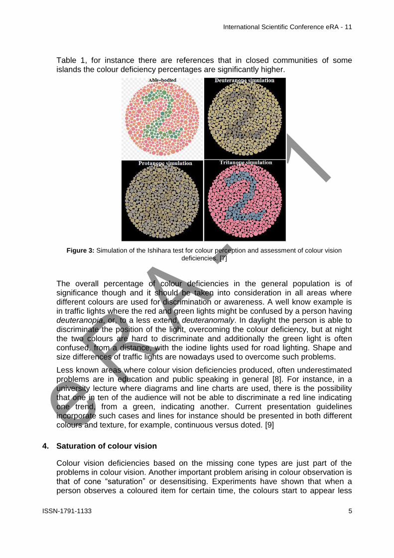
International Scientific Conference eRA - 11
ISSN-1791-1133 6
saturated and their differences tend to be reduced This is a combined cone and brain phenomenon that results in coloured images turning to be viewed as tones of grey when observed constantly without eye movement When a desensitised observer views an empty white area in a sequence to the image that caused the desensitisation then an afterimage with the opposite colours is viewed for a few seconds with no real image being present in the field of view This is one of the optical illusions that can occur to all observers
Figure 4 A demonstration of the afterimage effect The observer concentrates on the left-side colours for some time and then observes the black dot on the right The opposite colours are
observed on the white background [10]
This phenomenon is important in people working with colours and colour difference assessments For instance in textile dyeing industry a laboratory colourist that checks dyed samples for colour difference has to view them in a light cabinet in front of a grey background without observing each pair of samples for a long time because the longest they are observed the less the perceived saturation and colour difference Another case may occur in clothing department stores When coloured textiles are viewed in an environment with very saturated colours in the surrounding their colours appear less vivid Additionally when the lights used or the walls have a prevalent colour the eye of the observer is temporarily saturated in that colour leading to colour misjudgement of the viewed products These aspects of internal architecture and lighting are gaining importance in store designing [11]
Colour saturation is also a modern phenomenon arising from the constant exposure of the average observer to unnaturally saturated colours of screens like these of mobile devices and television sets Modern observers are getting accustomed to colour saturated images that are emitted rather than produced by light reflectance In addition the images themselves are virtually adjusted to be more saturated than in nature as part of contemporary aesthetics This phenomenon is greatly yet not exclusively observed in news backgrounds and childrenrsquos cartoons It could be described as a part of a ldquochromodystopiardquo and its effect is not yet scientifically explored It can be empirically proved though that colour trend in materials relating to children is constantly geared towards very saturated colours affecting food toys textiles and decoration among others [12] It remains to be scientifically examined if the long term exposure to very saturated colour gamut produces a permanent cone desensitisation or whether it affects psychologically the observer
International Scientific Conference eRA - 11
ISSN-1791-1133 7
5 Colour and optical illusions
Colour vision defects are not limited to the biological aspects of the eye construction Colour vision as previously explained is a complimentary phenomenon where both the eye and the brain collaborate Therefore a series of colour misjudgements can arise from the way the brain of the average trichromat observer explains and senses the colour and visual signals One of the general rules is that the brain has a tendency to average out colour sensations and visual shapes In that sense the phenomenon of colour saturation described previously is related to both cone saturation and brain fatigue of the colour sensation A well-known effect of the brain averaging things in the field of view is the fact that it covers the blind spots occurring to every observer in the place of the eye retina where the optic nerve is connected to the eye Due to the lack of cones and rods in the area where the nerve is connected to the eye each image arriving to the brain lacks a part which would theoretically be a black dot This black dot is not realised though since the brain covers the missing information with visual information from the surrounding area of the field of view A less pronounced phenomenon based on the same brain activity is the tendency of eye glassesrsquo stains to be almost unnoticeable after the user wears them for a certain amount of time
Figure 5 A simple test to access the blind spot of an observer
Another general rule is that the brain is making constant comparisons of the surrounding area of any coloured item before making its judgement of the supposedly perceived colour This is primarily observed in the chromatic adaptation of colour vision For example a coloured item has a very different fingerprint of emitted radiation in the varying set of lighting conditions yet it is usually perceived the same by the observer This is happening because the brain is constantly making comparisons between the observed item and empirically known colours for example a known white wall a piece of paper etc A good example is blue items in incandescent light that are perceived as blue although in practice their reflected energy more or less could characterise a grey Some extreme cases of chromatic confusion can arise artificially via specially designed computer generated images or even accidentally as in the case of a coloured dress in a confusing lighting environment
International Scientific Conference eRA - 11
ISSN-1791-1133 8
Figure 6 A photograph of a dress that initiated a heated debate over the internet where the dispute was upon whether the dress is blue and black or white and gold The dress was confirmed to be blue
and black The debate confirmed in a viral way the subjectivity of colour perception [13]
Based on the aforementioned general conditions certain visual circumstances can lead the brain to perceive and apprehend images in a non-objective way This is why these cases are called ldquoillusionsrdquo These illusions are not easy to classify but generally they can be broadly divided to shape and geometrical illusions motion illusions colour illusions and perceiving illusions
51 Shape and geometrical illusions
Shape and geometrical illusions are of the earliest ones examined Often the shapes or lines the produce the illusion were specially designed by psychologists or vision specialists of the time to deduce the way human brain interprets objects and sizes In this category belong the Oppel ndash Kundt the Zoumlllner Illusion the Bending illusions and the Cafeacute Wall illusion among others In these illusions there is a misjudgment of the size of lines and shapes their straightness or bending and other geometrical properties These illusions when understood they can be used creatively in textile designing and printing especially to cover body imperfections
Figure 7 The Cafe Wall illusion where the horizontal grey lines are parallel although they appear curved to the observer This illusion has been used in textile and architectural design extensively[14]
International Scientific Conference eRA - 11
ISSN-1791-1133 9
52 Motion illusions
Motion illusions are of the most impressive to demonstrate In these illusions otherwise static images appear in constant motion to the observer The illusions usually comprise spirals circles and ellipses In textile design these illusions can be used in fashion items and their effect can nowadays be fully realized with digitally printed designs
Figure 8 A demonstration of the motion illusion With the advent of digital printing on textile materials such patterns are incorporated in to fashion items [15]
53 Colour illusions
The colour illusions are mainly attributed to the aforementioned principle that the brain interprets colour by continuously contrasting each coloured area with its surroundings In this category belong the effects based on simultaneous contrast like the Bezold effect the contrast colour Illusion and the checker shadow illusion effect among others In the Bezold effect for instance the same red lines appear fainter when viewed in a white background and more saturated when viewed in a black one This effect has been used creatively in designs even in Western church glass vitreaux where the coloured glass pieces are placed in dark frames to accent their colour instead of being stuck together where the colours would appear less saturated
Figure 9 The checkerboard shadow illusion where the A and B squares on the board are of the same colour although they appear grey and white to the observer [16]
International Scientific Conference eRA - 11
ISSN-1791-1133 10
The checker shadow illusion effect is an interesting one in the sense that it belongs to a category that is specifically created via computer graphics to accent and demonstrate the brainrsquos subjectivity to colour and lightness interpretation
54 Perceiving illusions
The perceiving illusions are primarily related to what the brain interprets from a given image The images that give rise to such misconceptions are usually created in such a way that they include two incomplete sketches in one and the viewer is apprehending primarily and firstly the one of the two sketches The choice of the sketch is found to relate to psychological and empirical aspects of each observer
Figure 10 The Kanizsa Triangle illusion The average observer recognises two triangles although there is none
In the perceiving illusion category belong the cognitive illusions like the Kanizsa Triangle where the viewer interprets incomplete shapes as triangles since the brain has a tendency to virtually connect items in an ordered manner
6 Conclusions
Vision and colour interpretation is a complex process where the eye the neuron system and the brain cooperate for the final understanding of colours and shapes Colourimetry is based on the assumption that there is an average observer and this has helped greatly on the development and implementation of this particular science However the abnormal conditions in eye construction and in brain interpretation of colours and shapes are of significance Their illustration and enumeration in present paper aim by no means to undermine the importance of a mathematical standard observer Nevertheless it should be understood that colour and in a sense shapesrsquo understanding are brain sensations resulting from visual signals With these limitations or options into consideration we believe there is an area of research and application in colour and visual studies For example colour perception anomalies that occur to a minority but significant part of the population should be taken into consideration when designing educational material or public signalling among others On the other hand optical and colour illusions are
International Scientific Conference eRA - 11
ISSN-1791-1133 11
interesting aspects to illustrate colour judgment limitation and subjectivity and they can be used in creative textile design and fashion items especially combined with the modern applications of digital printed fabrics and 3D printing items
Acknowledgements
The authors would like to thank the Dyeing and Finishing Group of the Department of Textile Engineering at the Piraeus University of Applied Sciences under which permission part of this work was carried out as a graduate thesis The first of the authors would additionally like to thank the Directorate DNX of the Greek Naval Forces for the kind permission of allowing him to pursue his research as scientific collaborator with the Piraeus University of Applied Sciences
References
[1] R W G Hunt (2004) The Reproduction of Colour (6th ed) Chichester UK WileyndashISampT Series in Imaging Science and Technology pp 11ndash2 ISBN 0-470-02425-9
[2] Colour Blindness - httpsenwikipediaorgwikiColor_blindness
[3] Judd Deane B Wyszecki Guumlnter (1975) Color in Business Science and Industry Wiley Series in Pure and Applied Optics (3rd ed) New York Wiley-Interscience p 388 ISBN 0-471-45212-2
[4] Hering Ewald (1872) Zur Lehre vom Lichtsinne Sitzungsberichte der MathematischndashNaturwissenschaftliche Classe der Kaiserlichen Akademie der Wissenschaften K-K Hof- und Staatsdruckerei in Commission bei C Gerolds Sohn LXVI Band (III Abtheilung)
[5] The geometry of colour perception - httpwwwhandprintcomHPWCLcolor2html
[6] Spring Kenneth R Parry-Hill Matthew J Fellers Thomas J Davidson Michael W Human Vision and Color Perception Florida State University
[7] Simulation of Ishihara test perception ndash
httpscommonswikimediaorgwikiFileIshihara_compare_1jpg
[8] Crow Kevin L (2008) Four Types of Disabilities Their Impact on Online Learning TechTrends 52 (1) 51ndash5 doi101007s11528-008-0112-6
[9] Habibzadeh Parham (2015-01-01) Our redndashgreen world Australian Health Review doi101071ah15161
[10] Adaptation anchoring amp contrast - httpwwwhandprintcomHPWCLcolor4html
[11] Color amp Lighting Fundamentals for Communication ndash Roland Connelly RoLyn Group Color Consultants and Eric Haugaard CREE Inc ndash AATCC International Conference 2016
[12] CHROMODYSTOPIA Color in an RGB World - httpswwwlinkedincompulsechromodystopia-color-rgb-world-jeffrey-keith
[13] Rosa Lafer-Sousa Katherine L Hermann Bevil R Conway (29 June 2015) Striking individual differences in color perception uncovered by the dress photograph Current Biology 25 (13) R545ndashR546
[14] Cafe Wall Illusion By Fibonacci - Own work CC BY-SA 30
httpscommonswikimediaorgwindexphpcurid=1788689
[15] Illusory motion from change over time in the response to contrast and luminance Benjamin T Backus İpek Oruccedil Journal of Vision December 2005 Vol5 10 doi10116751110
[16] Adelsons Same Color Illusion - httpwwwbrainhqcombrain-resourcesbrain-teasersadelsons-same-color-illusion
International Scientific Conference eRA - 11
ISSN-1791-1133 12
Comparison study of the technical characteristics of battery energy storage
systems for residential use
M Palyvos 1 GA Vokas2 1 Dpt of Electronics Engineering Piraeus University of Applied Sciences Greece E-mail
mpalivoscosmotemailgr
2 Assoc Professor Dpt of Electronics Engineering Piraeus University of Applied Sciences Greece Tel +30 210 5381180 E-mail gvokasteipirgr
Abstract
One of the major energy issues of our days is reliable and effective energy generation and supply of electricity grids In recent years there has been experienced a rapid development and implementation of Renewable Energy Sources worldwide On one hand many Gigawatts of grid-connected renewables are being installed and on the other many Megawatts of hybrid renewable systems for residential use are being installed making use of electric battery systems in order to cover all daily energy and power needs during New types of batteries are being developed and many companies have made great progress providing a variety of electricity storage products The purpose of this research is firstly to highlight the necessity and also the importance of the use of energy storage systems and secondly through detailed technical simulation analysis using HOMER Pro-optimization software to compare the technical characteristics and performance of energy storage systems by various leading companies when installed in a residential renewable energy system with a specific load Results concerning the operation and the choice of a storage system are derived
1 Introduction
One of the dominant issues of our times pertains to energy and its short-term or long-term use The storage of energy in general and of electricity specifically has become a major issue which needs to be dealt with In order for energy to be stored it is transformed into various forms It can be transformed into Mechanical energy (pumped storage compressed air method flywheels) Chemical energy (Accumulators ndash batteries Flow batteries Hydrogen Accumulators) Magnetic energy (Superconducting Magnetic Energy Storage) Electrical energy (capacitors and supercapacitors) In fig1 the various energy storage technologies are presented
In the past years there has been increased activity with regard to the storage of electrical energy in batteries (Chemical energy)[1-4] This storage method is found to support numerous applications including integration of renewable energy sources transmission deferral frequency regulation peak management etc
International Scientific Conference eRA - 11
ISSN-1791-1133 13
Trends in electrical energy storage systems have to do with the improvement of various cell technologies [5 6] the combination of these storage systems with renewable energy sources [7]
Despite the satisfactory survey has been carried out on the optimization of cell technology and the combination of electrical energy storage systems there is a dark spot on their use on a real residential grid with its daily energy needs
Figure 1 Energy Storage Technologies
This presentation is a culmination of previous research studies and presents the comparative study of an energy storage system for a residential load with the use of batteries by various manufacturers and lists their technical characteristics indicating the optimal system
More specifically in section 2 of this paper the various cell technologies and their technical characteristics as well as specific energy storage systems ndash batteries will be presented and compared Next in section 3 after first describing the load on which the under technical analysis storage system is to be used the various energy storage system configurations will be simulated using ΗΟΜΕR Pro software In addition the technical characteristics of the individual proposed parts of our system shall be listed Finally in section 4 the results will be presented and discussed with analysis of the most dominant scenarios derived by the technical simulation of the energy storage systems by various manufacturers
2 Presentation of various battery cell technologies and systems
This paragraph lists the various battery cell technologies and offers a comparison of such technologies and the technical characteristics of energy storage systems by different manufacturers
21 Battery types-battery cell technologies
The most popular types of batteries are the following
- Lead ndash acid Batteries PbO2
International Scientific Conference eRA - 11
ISSN-1791-1133 14
- Lithium-ion Batteries Li-ion
- Lithium Iron Phosphate Batteries LiFePO4
- Sodium Sulfur Batteries NaS
- Nickel Cadmium Batteries Ni-Cd
- Vanadium-Red Flow Batteries REDOX
22 Main technical characteristics of various cell technologies Lead ndash acid batteries Their energy efficiency ranges from 60- 95 and their self-discharge rate amounts to 2-5 per month Their cycle life ranges between 300 ndash 1500 complete chargedischarge cycles whilst their manufacturing cost is low
Lithium-ion batteries They have significant energy density of 300-400 KWhm3 with an energy efficiency of 90 and a self-discharge rate of 5 per month their cycle life can often reach 10000 complete cycles They have a higher cost compared to other types of batteries
Lithium Iron Phosphate batteries LiFePO4 They have a high number of chargedischarge cycles (6000 cycles) their energy density ranges between 130 ndash 180 KWhm3 with a self-discharge rate of 3 They have a low manufacturing cost
Sodium Sulfur (NaS) Batteries Their energy density amounts to 150-240 kWh m3 and their performance ranges from 75 to 90 They have a relatively high manufacturing cost
Nickel cadmium battery Their energy density amounts to 50-75 kWhm3 and they have a relatively long cycle life of approximately 2000 ndash 2500 chargedischarge cycles Their self-discharge rate ranges from 2-5 whilst they also have a relatively high manufacturing cost
Vanadium redox battery (REDOX) They have low energy density of 16-33kWhm3 and their energy performance ranges from 75 ndash 80 They have a long cycle life of over 12000 chargedischarge cycles whilst their manufacturing cost is low
23 Comparison of technical characteristics of specific batteries This paragraph provides a table featuring the energy storage systems by various manufacturers with their individual technical characteristics
Company Hoppecke
Fenecon
Toshiba
Panasonic
Tesla
Siemens
Samsung
Cell technology
Li-ion
LiFePO4
Li-ion Li-ion Li-ion
Li-ion
Li-ion
Battery capacity (Ah)
154Ah
205Ah
160Ah
167Ah 195Ah
250Ah
200Ah
Nominal Voltage (V)
48V 512V
552V
48V 48V 58V 54V
Storage Capacity (kWh)
74kWh
10kWh
88kWh
8kWh 10kWh
148kWh
108kWh
Chargedischarge cycles
2500
6000
10000
4500 2500
4000
6000
International Scientific Conference eRA - 11
ISSN-1791-1133 15
System Efficiency ()
96 97
90 95 gt92
gt90
96
Operating temperature range(˚C)
(-25)-60
˚C
0-45 ˚C
(-30)-60 ˚C
(-20)-50 ˚C
(-20)-43˚C
(-30)-50˚C
(-10)-40˚C
Battery dimensions (Width-΄Height-Depth) (mm)
612mm467mm242
mm
581mm1270mm60
8mm
359mm123m
m187mm
224mm1380mm966mm
860mm1300mm18
0mm
320mm760mm240mm
280mm1200mm1140mm
Table 1 Technical characteristics of BESS for residential grid
In the above table from manufacturersrsquo data sheets the technical characteristics of all energy storage systems are shown focusing on their performance percentage and their chargedischarge cycles Systems featuring many chargedischarge cycles and a high performance rate are deemed to be the most suitable from a technical point of view for use in various networks
3 Simulation of different hybrid residential energy storage systems
31 Climate and Load profiles
In order to simulate the operational characteristics of various battery types the requirements of a domestic grid in the region of Styra Evoia (38˚96rsquoΝ 24˚142rsquoΕ) with a surface of 108 m2 have been taken into account The load and climate data will be common for all different battery types to be used in order to be able to compare their operation performance under reliably
The temperature and solar radiation data used originate from the National Meteorological Service for the period July 1983 ndash June 2005 As shown in Fig2 the average daily consumption amounts to 1127 kWh deviation is at 10 and the month with the highest electricity requirements is July The peak load hours are 1100 ndash 1400 and 1700-2100
Figure 2 Profile of the residential load
International Scientific Conference eRA - 11
ISSN-1791-1133 16
32 Technical characteristics of proposed equipment
In fig2 the block diagram of a battery energy storage system is shown and in fig3
Figure 2Block diagram of BESS
Figure 3 HOMER block diagram of BESS
The technical characteristics of the proposed battery energy storage system are listed below
- PV generator Mitsubishi single-crystal silicon 250 Watt PV panels connected in strings of 2 with dimensions of 1612101946mm
- Inverter a 5kW Bosch BPT-S 5 Hybrid is used the performance of which reaches 975 with approximately 20 years of life
- MPPT charger (dcdc) A Steca PR 3030 charge controller is used
- Battery type The residential product of 7 different manufacturers (Siemens Toshiba Samsung Hoppecke Fenecon Tesla Panasonic) is chosen
33 Other assumptions The technical analysis simulation and comparison of the energy storage systems will be carried out over 25 years In addition the depth of discharge of each battery energy storage system will not exceed 80 of the nominal capacity of the system
34 Scenarios studied With regard to the residential load cited in a previous paragraph the comparison of technical specifications of the energy storage systems will be based on following three main parameters a) Efficiency b) Cycles to failure at a discharge depth of 80 and c) Mean depth of discharge
4 Results presentation amp Discussion
41 System Efficiency In order to derive results regarding the efficiency of the energy storage systems the HOMER Pro simulation was used and following numerous test and simulations the following results were derived
International Scientific Conference eRA - 11
ISSN-1791-1133 17
Company Stored
Energy (kWhyear)
Energy transmitted to
Grid (kWhyear)
Efficiency
1 Fenecon 22854 22333 9772
2 Hoppecke 23093 22334 9671
3 Samsung 23354 22568 9663
4 Panasonic 22854 21835 9554
5 Tesla 23313 21152 9073
6 Siemens 25174 2284 9072
7 Toshiba 24462 2216 9058
Table 2 Battery Energy Storage System Efficiency
The efficiency of an energy storage system is the ratio of power transmitted to the
grid to stored power 100PowerStored
GridtoPowerdTransmitteEfficiency
Figures 4-10 depict the quantities being compared whilst the efficiency of each BESS is derived from the Energy In and Energy Out values
Energy in refers to the stored power and energy out to the power that is transmitted to the grid The total losses of a storage system are Storage depletion plus systems losses These values are presented on an annual basis and through this procedure the most efficient battery energy storage system is shown
Figure 4 Fenecon BESS
Figure 5 Hoppecke BESS
Figure 6Panasonic Bess
Figure 7 Samsung Bess
Figure 8 Siemens Bess
Figure 9 Tesla Bess
International Scientific Conference eRA - 11
ISSN-1791-1133 18
Figure 10 Toshiba Bess
42 Cycles to failure at a discharge depth of 80
From the data cited on the manufacturersrsquo datasheets on energy storage systems we can derive the results shown in table 3 for the chargedischarge cycles of each system at a discharge depth of 80
Company Depth of
Discharge Cycles to Failure
1 Toshiba 80 10800
2 Samsung 80 7200
3 Fenecon 80 6800
4 Siemens 80 5400
5 Panasonic 80 5000
6 Tesla 80 2500
7 Hoppecke 80 2500
Table 3 Cycles to Failure
43 Mean State of Charge The last axis on which the comparison of the storage systems is based is the mean monthly state of charge which is expressed as a percentage and is a function of the gridrsquos monthly electricity requirements and the storage capacity of such grid
Company Mean Monthly
State of Charge ()
1 Toshiba 7125
2 Samsung 7125
3 Tesla 6958
4 Panasonic 6900
5 Fenecon 6833
6 Siemens 6816
7 Hoppecke 6000
Table 4 Mean Monthly SoC per BESS
The results in the previous table are a product of the simulations as depicted in figures 11-17 which show the mean monthly state of charge
International Scientific Conference eRA - 11
ISSN-1791-1133 19
Figure 11Hoppecke BESS
Figure 12Fenecon BESS
Figure 13Panasonic BESS
Figure 14Samsung BESS
Figure 15Siemens BESS
Figure16Tesla BESS
Figure17Toshiba BESS
5 Conclusions
In the following table 5 the aggregated results of the performed comparisons carried out for 7 different energy storage systems are presented
Company System
Efficiency ()
Cycles to failure (Depth of Discharge
80)
Mean Monthly State of Charge
()
Battery type I 9671 2500 6000
Battery type II
9772 6800 6833
Battery type III
9663 7200 7125
International Scientific Conference eRA - 11
ISSN-1791-1133 20
Battery type IV
9554 5000 6900
Battery type V
9073 5400 6816
Battery type VI
9072 2500 6958
Battery type VII
9058 10800 7125
Table 5 Results of the technical analysis
Based on the results of the simulation an engineer could state with certainty that the system which best meets the requirements of the domestic grid for which the study and simulation were carried out is the one by Battery type VII since over a period of 25 years it is the one with the longest life duration whilst is mean monthly state of charge remains at higher levels compared to the other energy storage systems
On the other hand if the requirement of our grid was for a battery energy storage system with high performance the battery type II would be the most effective choice so this systemrsquos performance should be 9772
Finally after the comparison of the technical characteristics for different battery types through HOMER Pro software the most critical technical characteristics of a BESS are
- Cycles to failure In a lifetime project of more than 15-20 years the most efficient system is the one that provides more cycles of chargedischarge
- State of charge By discharging an energy storage system between 50-70 can be achieved an increase in systemrsquos lifetime
- Efficiency The ability of a battery energy storage system to deliver grid as the largest possible quantity of the stored electric energy is the most critical criterion for the most efficient system
- Other quantities Quantities such as the nominal voltage nominal storage capacity batteryrsquos capacity depend on cell technology and the cell stacks that are assembled to create a battery storage system
References
[1] Gonzaacutelez FD Sumper A Bellmunt OG Robles RV A review of energy storage technologies for wind power applications Renewable and Sustainable Energy Reviews 2012162154-71
[2] Kaldellis JK Zafirakis D Kavadias K Techno-economic comparison of energy storage systems for island autonomous electrical networks Renewable and Sustainable Energy Reviews 200913378-92
[3] Sauer DU Storage Systems for Reliable Future Power Supply Networks In Urban Energy Transition Droege P editor Elsevier 2008
[4] Zafirakis D Overview of energy storage technologies for renewable energy systems In Stand-alone and hybrid wind energy systems technology energy storage and applications Kaldellis JK editor Woodhead Publishing 2010
International Scientific Conference eRA - 11
ISSN-1791-1133 21
[5] Zhang Q Multifunctional separatorinterlayer system fir high stable lithium sulfur batteries Progress amp prospects 2015 Elsevier BV
[6] X-B Cheng C Yan J-Q Huang P Li L Zhu L Zhao Y Zhang W Zhu S-T Yang Q Zhang The gap between long lifespan Li-S coin and pouch cells The importance of lithium metal anode protection 2016 Elsevier BV
[7] Marc Beaudin Hamidreza Zareipour Anthony Schellenberglabe William Rosehart Energy storage for mitigating the variability of renewable electricity sources An updated review 2010 Elsevier BV
[8] Table 3 Cycles to Failure httpwwwtoshibacomticpower-electronicsscib-rechargeable-battery
[9] Table 3 Cycles to failure httpsfenecondepagestromspeicher
[10] Table 3 Cycles to failure httpwwwhoppeckecomenproducttrak-power-lion
[11] Table 3 Cycles to failure httpwwwsiemenscominnovationenhomepictures-of-the-futureenergy-and-efficiencysmart-grids-and-energy-storage-bottled-sunlighthtml
[12] Table 3 Cycles to failure httpwwwsamsungsdicomessindexhtml
[13] Table 3 Cycles to failure httpwwwpanasoniccomauconsumerenergy-solutionsresidential-storage-battery-systemlj-sk84ahtml
[14] Table 3 Cycles to failure httpswwwteslacompowerwall
International Scientific Conference eRA - 11
ISSN-1791-1133 22
Fancy yarns for fashionable fabrics recent developments
Cristina Piroi
Faculty of Textiles - Leather and Industrial Management
Technical University Gheorghe Asachi Iasi Romania Tel +40 232 701143 E-mail cpiroitextuiasiro
Abstract
This paper presents the solutions currently offered by the textile machinery producers
for producing single spun fancy yarns as response to the customersrsquo demands for
spinning machines more flexible highly productive and easy to operate able to
manufacture a large variety of regular or fancy yarns specially designed for particular
applications and affordable
1 Introduction
Manufacture of yarns with a high degree of regularity is one of the most important aims for spinners However for some application a certain degree of irregularity is required to produce fabrics with a particular appearance such as uneven and rough surface that gives the feeling of moving or variations of colour intensity that make the fabrics more interesting for customers The yarns characterised by this kind of desirable lsquodefectsrsquo are known as effect yarns or fancy yarns they contain deliberately introduced irregularities arising from changes in yarn twist andor yarn count (thick or thin places) [1]These yarns are produced by using devices special developed for this purpose that creates discontinuities in yarn structure andor in their colour
During the last several years on the clothing market as well as in the furnishing and home textiles sectors the demands for refined fabrics with more distinguishing features increased continuously Consequently the demand for fancy yarns used for manufacturing new and modern fabrics has grown accordingly Whether used for outerwear home textiles upholstery fabrics or industrial textiles fancy yarns account for an increasing share from the total quantity of yarns produced worldwide
Presently fancy yarns are an essential feature of the modern fashion The denim production is a typical application for fancy yarns In the manufacturing of these fabrics yarns featuring a large numbers of effects are necessary so the ldquofancy denimrdquo effects to be clearly visible in the finished fabric These fancy yarns for denim are characterised by effects with natural appearance which are very similar to natural yarn defects [2]
The development of new types of fancy yarn for fashionable fabrics allows spinners or integrated textile groups to strengthen their relationships with the customers by offering them not only common yarn but also high-quality value-added products [3]
International Scientific Conference eRA - 11
ISSN-1791-1133 23
2 Types of fancy yarns
As a general definition fancy yarns are those yarns in which some deliberate decorative discontinuity or interruption are introduced of either colour or form or of both colour and form These discontinuities are incorporated with the intention of producing an enhanced aesthetic effect In recent years there has been an important increase of the interest in applications of single spun fancy yarns and fancy doubled yarns and these yarns have now a considerable commercial significance Most fancy yarns are produced by specialist fancy spinners using machines modified or developed for the purpose Others are produced from lsquofancy sliversrsquo which are used as minor components in yarns made by spinners using normal equipment [4]
Apart from the fancy doubled yarns which have most often a complex structure consisting of lsquocorersquo threads an lsquoeffect materialrsquo and in the more complex cases a lsquobinderrsquo which holds together the entire structure other types of fancy yarns may be obtained directly on the spinning machines by varying the spinning process conditions
The modern ring-spinning and rotor spinning machines can be equipped with certain devices able to produce single spun fancy yarns The desired effects in yarn are obtained by use of a microprocessor-controlled servomotor system which controls the spinning process This allows change of the rollers speed and consequently of the draft andor the twist enabling thus the creation of yarns with various effects Based on the types of effects introduced the single spun fancy yarns can be grouped into four categories slub yarn multi-count yarn multi-twist yarn and multi-effect yarn
Slub yarn
Slub yarn is the best-known and probably the most frequently used type of fancy yarn A slub yarn is one in which slubs are intentionally created to produce a desired effect Basically the slubs are thick places in the yarn They can be built in form of a gradual change in thickness with only a slight thickening of the yarn followed by its thinning to achieve the base yarn count Alternatively the slub may be three or four times the thickness of the base yarn and that thickness may be achieved for a very short length of yarn [4] Usually the slub yarns are characterised by rather short effects with the length varying between 3 and10 cm
On the ring spinning machine the yarns with slub effect are produced by varying the speed of the middle and back bottom rollers while the speed of the front roller as well as the spindles speed are kept constant This means that the twist per meter in the yarn remains the same (T1=T2) and the yarn are characterised by count
variations with varying twist factor ) (Fig1) [1]
On the rotor spinning machine the slub yarns are produced usually by incorporated electronically-controlled devices that briefly accelerate the feed roller The working principle of these devices is based on the variation of sliver amount supplied into the rotor while the rate of yarn delivered to the bobbin is kept constant However as a result of the doubling action inside the rotor it is not possible to produce slubs shorter than the circumference length of the rotor Any variation in the amount of
International Scientific Conference eRA - 11
ISSN-1791-1133 24
fibres supplied in rotor is spread over a minimum length which is equal to the rotor circumference As example for a rotor diameter of 36 mm the slub effects on rotor spinning machines are at least 113 cm long [1]
Multi-Count yarn
A multi-count yarn is a fancy yarn consisting of lengths of different yarn counts The multicount effect is achieved by controlled changes of yarn thickness on a certain
length while the twist factor is maintained constant ) To obtaining the mass variation along the yarn and create the fancy effects the main draft is periodically reduced through the temporary increases in speed of the back bottom roller and middle bottom roller The twist is adapted to each portion of yarn with different count so the yarn shows a succession of segments with various thickness but with the same twist factor (Fig2)
Figure 1 Slub yarn Figure 2 Multi-count yarn
A multi-count yarn is similar in many respects to slub yarn but due to the modified twist has a higher tenacity in the thin zones In contrast to slub yarn the effects have a longer wavelength giving a special look to the fabrics
Multi-Twist yarn
The fancy yarns with multi-twist effect are produced by applying different twist
factors ) and consequently different twist per meter (T1 T2) to the yarns with constant count (Fig3) These differences in twist creates variations in the yarnrsquos dye intake allowing to obtain fabrics with a special appearance Usually multi-twist yarns are produced with rather long effects of 10-50 cm
The multi-twist fancy yarn is obtained by means of the controlled and accurate acceleration of the front roller The twist variations in the yarn are incorporated by varying the delivery speed of the spinning machine whereas the total draft remains constant
Multi-effect yarn
Multi-effect yarn is a fancy yarn featuring a combination of slub effects multi-count effects and multi-twist effect (Fig4) The variations can be freely programmed in the
case of multi-effect yarn A change in mass can be combined with a twist factor which is not predefined This means that the twist and change in mass in the yarn can be freely selected
Figure 3 Multi-twist yarn Figure 4 Multi-effect yarn
International Scientific Conference eRA - 11
ISSN-1791-1133 25
Lately the fancy yarns obtained on ring-spinning machines and rotor spinning machines have become very popular they and are used most frequently in the denim production for upholstery fabrics and drapes as well as in production of single jersey and fine outerwear fabrics (Fig5)
Figure 5 Various types of fancy yarn fabrics (wwwrhytmfabricscom wwwetsycom)
3 Slub systems for fancy yarns
The Swiss company Amsler Tex provides solutions for production of fancy yarns on all kinds of spinning machines The company cooperates with all important manufacturers of spinning machinery (Marzoli Rieter SchlafhorstZinser Totota
International Scientific Conference eRA - 11
ISSN-1791-1133 26
etc) to develop complete systems for production of fancy yarns as alternative to ordinary yarn on the same machine [5]
Amsler systems are compatible with nearly any type of existing or new ring and open-end spinning frames The devices are installed either with a differential gear or with a direct drive system With the differential gear the creation of the slub is made with an individual slub drive The production of the base yarn is still driven by the basic drive of the spinning machine The high dynamic movement for the slub creation is superimposed through the differential gear This construction enables slub creation without thin places and prevents yarn breakage after a power failure
For the ring spinning frames Amsler provides three types of slub systems the basic slub system the multicountmultitwist system (MCMT) and extreme short slub system (XSS) (Table 1) Figure 6 shows the diagram of Amsler slub device on the ring spinning machine including multi-countmulti-twist function [5]
Amsler ring spinning systems
Minimal slub length
(milimeters)
Maximal number of slubs
(slubsmeter)
Minimul distance between yarn count
change
(meters)
Basic slub 30 10 -
MCMT (incl slub)
30 10 15
XSS 15 - 20 12 - 15 05
Table 1
Figure 6 Diagram of Amsler slub device on ring spinning machine [6]
For open-end frames Amsler Tex offers also three slub systems the standard system the high performance system and the high performance cooling system (Table 2) These systems may be upgraded with the optional multi-count multi-twist function [5]
International Scientific Conference eRA - 11
ISSN-1791-1133 27
Table 2
Figure 7 Working principle of Amsler open-end slub system [5]
Amsler open-end systems Maximum
number of slubs minute
Standard S
TD 150
High performance H
P 200
High performance cooling
HPC
300
All yarn effects produced with Amsler devices are digitally programmed using a dedicated design software Amsler E-Profi is a comprehensive software system for professional slub yarn development and production It has a modular structure and can also include a digital yarn scanner for quality control and slub yarn design [5]
The most comprehensive E-Profi package allows
Advanced creation of slub yarn programs (multicountmultitwist statistics XY yarn preview)
Slub view (analyzing digitized yarn)
Generation of slub yarn programs out of digitized yarn
3D fabric preview (based on weaving and knitting parameters)
Scanner software(laser or flatbed-scanner
During the spinning process the computer controlled drafting system uses the created slub yarn programs to modify the draft in order to obtain the designed fancy yarns
Figure 8 Creating effect yarn [5]
International Scientific Conference eRA - 11
ISSN-1791-1133 28
Figure 9 Designing fashion using E-Profi with fabric preview module [5]
4 Available solutions for producing fancy yarn
Marzoli Fancy Yarn Device
The first manufacturer who introduced a fully integrated device for fancy yarns on its spinning machines was Marzoli in 1999 There are four types of slub effects that can be obtained through continuous variation of the speed of the drafting rollers slub multi-count multi-twist and reverse slub The various combinations among these four slubbing effects can create a large diversity of yarn and fabric designs (Figure 10)
The slub effect is obtained through continuous variations of the main draft by increasing the speed of the back and middle rollers This causes reduction of the main draft and determine the increase of yarn thickness Otherwise to obtain the reverse slub effect the draft variation is negative leading to reductions of the yarn thickness
To design a slub Marzoli system requires setting its length in millimeters its thickness as a percentage of the base yarn (multiplier) and its pause (distance between one slub and the next) in millimeters [6]
Figure 10 Various types of slub yarns [6]
Usually the slubs length is set between 30 to 100 mm but in some cases slubs could be even shorter in order to produce an effect called malfile ie small and frequent slubs that create an effect similar to the natural irregularity of the yarn
The manufacturer claims that Marzoli Fancy Yarn Device is able of producing slubs shorter than 20 mm with up to 20 slubs per meter without compromising the yarn quality and strength by using last generation electronics high efficiency motors
International Scientific Conference eRA - 11
ISSN-1791-1133 29
mechanical transmissions light and solid as well as special acceleration ramps that lasts less than 01 seconds [10]
The multi-count effect is obtained through prolonged variations of the main draft The result is a yarn with different counts along its length Usually this effect is used together with the multi-twist effect in order to obtain interesting effects on fabric
The multi-twist effect entails twist variations that change the yarn diameter its compactness and consequently the behaviour in dyeing This creates interesting lighter and darker areas into the yarn and in the final product
The multi-count and multi-twist effects can be used together to create other interesting effects in fabric In this case the yarn does not have a constant count nor a constat twist For each count is applied a different twist based on selected
constant bdquo rdquo This effect combination is obtained through a variation of the main draft to modify the count and a variation of the front roller speed to modify the twist
Marzoli Fancy Yarn Device is capable of producing fancy yarns of variate forms and designs without requiring any modification to the spinning frame The variation in twist and draft are accomplished by modifying the speed of the independent motors that are already installed on the spinning frame
Rieter VARIOspin Fancy Yarn system
VARIOspin fancy yarn device is the result of cooperation between Rieter AG the supplier of systems for short-staple spinning and AmserTex provider of systems for producing fancy yarns The system is based on the drafting system drive FLEXIdraft which allows separate actuation of the drafting system drives and can be programmed by the user
The feed bottom roller (A) and the center bottom roller (B) are driven by an inverter-controlled motor while the delivery bottom roller (C) is driven separately by another inverter-controlled motor (Fig11) The bottom rollers of the drafting system are independently driven so it can change their rotation speed in accordance with a preset program required to produce a particular yarn effect [7]
Figure 11 FLEXIdraft drafting system drive for fancy yarn production [7]
The slub yarns are obtained by changes in mass effected via the control of the feed bottom roller and the middle bottom roller For an increase in mass they are accelerated thus reducing the total draft For a reduction in mass they are slowed down so total draft is increased To obtain the change in mass without the twist modification the yarn delivery speed and the spindles speed remain constant
International Scientific Conference eRA - 11
ISSN-1791-1133 30
When multi-count yarns and multi-effect yarns are spun changes in mass together with modification of twists per meter are performed all drafting bottom rollers changes their peripheral speed simultaneously in coordination with each other The yarn delivery speed is also changed
Rieters rotor spinning machines can also be equiped with the VARIOspin devices for fancy yarn Any desired effects can be created slub yarns multi-count yarns multi-twist yarns and combined multi-effect yarns The yarn count of the base yarn in fancy yarn spinning is Ne 3 to Ne 40 (Nm 5 to Nm 68) The change in mass of the effect is set in practice at -20 to +400 while twist modification varies between 50 and 150 [2]
More pronounced effects can be achieved by reducing production speed to some extent since a large increase in mass requires more time In principle the draw-off speed for slub sections is the same as for the base yarn However the number of possible effects per unit of time depends on the performance of the feed drive In some cases the delivery speed is reduced for short effects also featuring short spacing [2]
Behind every fancy yarn system there is a program with which the effects can be defined ie programmed The program for Rieter ring-spinning machines is VARIOspinData It enables effect patterns and their repeats to be programmed visualized optimized and managed on the computer (fig11) The formation of a moireacute structure in the fabric caused by a regular effect pattern can be prevented by modifying the program if such a structure is unwantedThe effect patterns created can be transferred to any Rieter ring-spinning machine with a VARIOspin device via a USB stick or optionally via the SPIDERweb data collection system [7]
Figure 11 Programming effects with VARIOspinData [7]
1 - Input of fancy yarn parameters 2 - Visualization of the fancy yarn 3 - Visualization of the yarn surface
International Scientific Conference eRA - 11
ISSN-1791-1133 31
TOYOTA Fancy Yarn Spinning Device
The ring-spinning machines RX300E from Toyota Industries can include optionally the Fancy Yarn Spinning Device that allows manufacture of many types of fancy yarns such as slub yarns multi-count yarns and multi-twist yarns
The operating principle of this device is based on e-Draft System the independently drive system for all three bottom rollers of the drafting systemThese rollers are driven by specialized servo motors which allow setting and changing the speed of each draft roller freely This makes possible slowing down the front roller andor speeding up the back roller in order to produce varied effects in yarn
Types of yarn that can be manufactured on Totota ring-spinning machines RX300E [8]
Positive slub yarn (increase up to 500 comparing the cross-section of base yarn) can be obtained with one of the following options
Front roller deceleration control (with change to twist) Back roller acceleration control (with no change to twist) Combined control of the front and back roller (degree of twist change
can be adjusted)
Negative slub yarn (decrease up to 30 comparing the cross-section of base yarn)
Back roller acceleration control
Multi-count yarn Fixed number of twisted threads (2-6) Fixed number of twists (1-70 twistinch) Any number of twists (1-70 twistinch)
Multi-twist yarn Number of twisted threads 15 - 10
Multi-count+Multi-slub
Slub on slub
Natural slub like
The special developed software Data Creator for Fancy Yarns makes it easy to record and manage the pattern simulations and settings data
Saurer Fancypilot
To meet the demands of a market for fancy yarns with continuous growth the Saurers strategy was initially focused on developing integrated user-friendly solutions for ring and rotor spinning machines Additional mechanical devices were retrofitted to the machine to produce fancy yarns but this approach led to reductions in productivity and also in increases of system complexity
Currently the ring spinning machines Zinser with electronic drafting control system ServoDraft are available for producing fancy yarns both from short-staple and long-staple fibres The draft and the twist can be varied in a controlled manner so slubs of different thickness and lenghts can be introduced in yarn The twist can also be varied for the production of multi-twist yarns and in contrast to previous retrofit solutions now can be spun even yarns with long-wave draft variations [9]
International Scientific Conference eRA - 11
ISSN-1791-1133 32
For rotor spinning machines was developed Fancynation a complete modular system hardware and software fully integrated available both for automatic rotor spinning machines Autocoro and semiautomatic BD machines On the Autocoro 9 this cost-effective option allows to produce up to 5 different fancy yarns simultaneously or fancy yarns and standard yarns in parallel on the same machine [11]
FancyPilot is the software used on the Zinser ring spinning machines and Schlafhorst rotor spinning machines to design fancy yarns The effects are designed managed and controlled on a PC with all design parameters lot and customer data being stored in a database that can be used also in production of standard yarns
5 Conclusion
Although fancy yarns account for only a small proportion of total yarn volume they are in considerable demand depending on fashion trends During the last years the demands for refined fabrics with more distinguishing features increased continuously These fabrics often created by fashion designers provide a higher profit margin when compared with traditional fabrics so more and more spinners are interested to include fancy yarns in their product range
The modern ring-spinning and rotor spinning machines can be equipped with slub devices able to produce single spun fancy yarns The desired effects in yarn are obtained by use of a microprocessor-controlled servomotor system which controls the spinning process There are four basic types of slub effects that can be obtained slub multi-count multi-twist and reverse slub The various combinations among these four slubbing effects can create a large diversity of yarn and fabric designs
The possibility of producing fancy yarns and regular yarns on the same spinning machines by employing new and more advanced integrated slub devices allows to the spinning mills diversifying the range of products without additional running costs as well as strengthen their relationships with the customers
References
[1] R Maier Through thick and thin ndash with Rieterrsquos VARIOspin Link-The customer magazine of Rieter Spun Yarn Systems Vol 22 No 562010 p8-9
[2] M Werner Rotor-spun yarns with fashionable effects for ldquofancy denimrdquo Link-The customer magazine of Rieter Spun Yarn Systems Vol 22 No 562010 p12-13
[3] Amsler-Tex Slub yarn devices for spinning machines httpwwwptjcompk200802-08PDF-February200849-20Spinning20-20Amslerpdf
[4] RH Gong RM Wright Fancy yarns Their manufacture and application Woodhead Publishing Ltd Cambridge England
[5] Technology for textile fashion Brochures of Amsler Tex company [6] Fancy Yarn-Technology for superior flexibility Brochures of Marzoli SpA company [7] R Maier VARIOspin ndash for individual effects in ring-spun and compact yarns Link-The customer
magazine of Rieter Spun Yarn Systems Vol 22 No 562010 p10-11 [8] Ring spinning frame RX300 Brochures of Toyota Company [9] Saurer Fancynation - httpsissuucomoerlikontextilegmbhdocsfancynation [10] httpwwwmarzolicomen [11] httpschlafhorstsaurercomenautocoro-9
International Scientific Conference eRA - 11
ISSN-1791-1133 33
Nonconventional technology for production of decorative cushions
IFilip1 CSava 2 MCiocoiu2 GPriniotakis3
1 SC TAPARO Tg Lapus Romania E-mail ioanfiliptaparoro
2 Textile - Leather amp Industrial Management Faculty ldquoGheorghe Asachirdquo Technical University Iasi Romania
E-mail csavatextuiasiro mciocoiu41yahoocom
3 Textile Department Piraeus University of Applied Sciences Greece gprinteipirgr
Abstract On the market there is a high demand for decorative cushions essential components of the sofas The market are offering lines for the production but at big price and consequently the TAPARO Company Romania propose achieving a production line of decorative cushions with the original conception but with reasonable price For this was used the recovered equipments from cotton spinning mills but and equipment own conception The decorative cushion is from the same material like the sofa and the cushion basket is made of nonwoven textile and filled with a mixture of polyester fiber and polyurethane sticks Maintaining of the cushion geometry for a long time depends on the size and weight of cushion and of the basket of cushion with multiple cells In the paper are presents the changes did on the spinning machines to be used with new function and also achived the machinery of own conception Also in the paper are showed the quality characteristics of the decorative cuchions Keywords fiber polyester polyurethanesticks mixture cushion
1 Introduction
Particularly because of high demand for decorative cushions essential components of the TAPARO Company Romania product the sofas led to the idea of achieving a production line of decorative pillows from original conception considering the high price of identical lines on the market[12] Necessity the production line of decorative cushions was imposed from increased the production of sofas and for another hand of the realization possibility of the line at reasonable price using some of the recovered equipment from cotton spinning technological lines but and equipment own conception Unlike conventional cushion the decorative cushion is from the same material like the cover of sofa and the cushion basket is made of nonwoven textiles and the filling is a mixture of polyester fiber and polyurethane waste Maintaining of the cushion geometry for a long time depends on the size and weight of cushion and of the basket of cushion with multiple cells The mixture of polyester fibers and polyurethane cut waste is an alternative to replace conventional materials in cushions namely -polyester fibre can be fibre at first usage or fibre recovered from nonwoven textiles after cutting panels used in making sofas chairs etc
International Scientific Conference eRA - 11
ISSN-1791-1133 34
-superior utilisation of polyethylene waste with density between 21 to 25 Kgm3 resulting in the process of obtaining components of the sofa - the presence of the polyurethane cut into sticks and individualization polyester fibres in a homogeneous mixture assure good volume and the form of decorative cushions By using polyurethane waste as a component of the mixture forming cushions is assured a significant contribution to maintaining a clean environment Basically best it behaves in a cushion the mixture from silicone polyester fibre 30-32 mm cutting length and density 6-7 dtex and the polyurethane sticks [3]
2 Nonconventional technological line for decorative cushions
Some of the machines from unconventional line were bought from spinning mills mills which were either upgraded or were closed for various reasons These machines have been modified according to the new mode of use and the other part of the equipment from line have been designed and manufactured in the Company TAPARO (figure 1)
Figure1 Schematic unconventional production line of decorative cushions
1 Silicone polyester fibre bales 2 Sack with polyurethane sticks 3 Hopper feeding Trutzschler with weighing 4Opener 5 Condensor Trutzschler 6 Collector conveyor with striking point 7 Transport
ventilator Trutzschler 8 Cleaner with two axial drums Trutzschler 9 Opener Rieter 10Presortat with pressure gauge 11Compressed air pipe 12 Opener Rieter ERM model B5 13 Table for filling cushions 14 Order pedal for filled the cushion 15 Cushions conveyor 16 Electronic balance
17 Sewing machine
3 Made changes on machineries from spinning
Because the line is a succession of machines some of which were used in spinning cotton in what follows will present these changes to equipment and machinery own conception
31Hopper feeding Trutzschler for polyester siliconate fibres
Feeding of fibrous material in the technological process of obtaining decorative cushions is carried with the hopper feeder Trutzschler type KNW [4] (noted 3 in fig 1) who underwent modifications shown in Figures 2 and 3 in comparation with the
International Scientific Conference eRA - 11
ISSN-1791-1133 35
original version The cylinder equalizer is replaced with the lattice equalizer 9 equipped with slats with conic section The space between the lattice equalizer and inclined lattice 10 is at least 4mm thus creating a potent effect of teasing by wresting
Figure 2 Hoppe feeder Trutzschler type KNW with weighing for polyester fiber
1-cylinder with discs 2-photodetector 3- bunker dispenser 4- the superior mobile flap 5 ndash the mobile flap
bunker 6-conveyor 7- main engine (particularly resistant construction to frequent starts) 8- engine driving of
the main engine 9- feeder lattice equalizer 10- spiked lattice
32 Original opener design
Because the the raveling of the fiber tuft in the hopper feeding is insufficient was placed after this a designed an original opener (noted 4 in fig 1) with the cylinder equipped with saw-tooth clothing Thus the raveling of silicon fiber tuft is realized in restraint state The preset quantity of fiber depending on the recipe of mixing falls from basket 1 on the feeder table 2 inclined at 45o Thus it form a fibrous layer pressed by the wood cylinder 3 The gauge between feeder cylinder 4 and feed lattice 2 adjust the material quantity from the dispenser and the thick fibrous layer formed on the feeder lattice The Cylinder 6 has 248 mm diameter is with saw-steel clothing Graff C-55-6
Figure 3 The original opener for the polyester fiber 1 - basket 2 - feeder table 3 - cylinder pressure 4 -cylinder feeder 5- cover feeder cylinder 6- devil
cylinder 7- cover devil cylinder 8 -discharge pipe of individualized fibers 9- grill 10 semi-stiff linear
To achieve an more advanced loosening was fixed to the side walls one semi-stiff lineal 10
International Scientific Conference eRA - 11
ISSN-1791-1133 36
33 Hopper feeder Trutzschler for polyurethane sticks
The supply of polyurethane sticks with the participation quota imposed by recipe is via a same hopper feeder Trutzschler KNW [4] (noted 3 in fig 1) at which were made two key changes - the equalizer role of inclined lattice is canceled - nail bars are replaced with metal scraper
Figure 5 Hopper feeders with inclined lattice with with metal scraper a-side view of hopper feeder1- inclined lattice 2 - plate scraper profile
As shown in fig 5 collecting conveyor table 1 via these scrapers 2 takes the relatively constant quantity of sticks polyurethane and will unloaded its in the feeder Trutzschler KNW
34 Conveyor collector with striking point (noted 6 in fig 1)
Figure 6 Conveyor collector with striking point (noted 6 in fig 1) 1-transport table 2-inclined conveyor 3- opener 4-permanent magnet 5-pipe I- LVS capacitor
I hoper feeder for polyester fibersII-hoper feeders for polyurethane sticks
The conveyor 1 with polyester fibres individualized discharged from the feeder I and with the polyurethane sticks downloaded from the feeder II brings its in the work area of the opener cylinder 3 and conveyor 2 adjusted accordingly with it and take the material ldquosandwichrdquo composed of polyester fibres and polyurethane sticks and pneumatically are conveyed under the permanent magnet 4 and conduit ventilator Trutzschler 425 TV 5
International Scientific Conference eRA - 11
ISSN-1791-1133 37
35 The homogenization of mixture from tow components
The quality of decorative cushions depend of the homogeneity of the mixture of the components fibres polyester and polyurethane sticks to prevent defects (improper filling of the cushions etc) The correct adjustment of feeders ensures the supply adequate quantities of the components but is insufficient for intimate blending To obtain a good mixture were used two machines with the cleaning role in cotton mill which in this technological line provide an intimate mixing of these two components or obtaining a intimate mixture of these two-component in line are used two machines with cleaning and teasing role in cotton mill but which in this case provide intimate mixing of the two components and they are shuffler axial Truschler AXI- FLO and opener Rieter ERM (denoted on fig 1)
351Shuffler axial Trutzschler AXI-FLO
To achieve an intimate mixture between siliconate polyester fibres and polyurethane sticks in the shuffler axial Trutzschler AXI-FLO [4] (noted 8 in fig1) was make the following adjustments -the fan provides the transportation of the mix from two-component with air speed from 12 -15 m s but is advisable using the lower limit of speed to maintain in instalation the mixture more time for enhancing the mixing effect - Bars of grids 5 and 6 were completely closed - Speed drum 3 is 422 rot min left sense of rotation - Rotations drum 4 is 400rot min left sense of rotation - Flap 9 open to positions 78 on the nameplate ensuring for the fibrous material a spiral route about 6-8 tours
Figure 7 Shuffler axial Trutzschler AXI-FLOW 1 supply line 2 screen (damper) 3 4 mixing drums 5 6 grills 7 piece adjustable 8 exhaust pipe
(tubing) 9 flap 10 baffle plate 11 the handle for adjusting the grill 12 waste box 13 observation windows 14 access doors
352Opener Rieter ERM
At the exit of this machine the fibrous mixture two-components is sent to storage to upper chambers 2 (Fig 7) because the simultaneous operation of the four Trutzschler FBK 12 feeders used for filling the cushions ( noted 9 in fig 1) impose keeping constant the amount of material and requires the introduction of some bunker with appropriate storage capacity and with possibility to start and stop the flow depending on mixture consumption (fig 7) For this scope is used the opener
International Scientific Conference eRA - 11
ISSN-1791-1133 38
Rieter B5 5 [5] with a vertical hopper 2 at whose outer wall lamellar 3 allows removing the dust and air At the bottom of the hopper there is a smooth cylinder 6 and a perforated drum 11 that allow the formation of a layer of the mixture over the pair of feeders cylinders 7
Figure 8 Opener Rieter ERM
1- fibers supply line 2- vertical hopper- 3 posterior lamellar wall 4 -pipe exhaust air and dust 5- waste outlet pipe 6- cylinder smooth 7- feed cylinder 8- grill 9- air outlet 10- cylinder with
rigid garnish 11- drum sieve12- pipe for fibrous material evacuation
36 Installation for dosing of the fibrous unconventional mixing
For transportation the unconventional mixture from opener Rieter to each the cushion basket is used a pneumatic installation and 4 feeders Truzschler FBK (noted 12 in fig1) Pneumatic installation ensure uniform filling of the upper bunker of each feeder Truzschler FBK and by through the lower bunker of it assures pneumatic dosing and filling the mixture in the cushion basket
Figure 9 Pneumatic supply system for mixture of polyester fiber -polyurethane sticks 1-Opener Rieter2 Transport ventilator TV 425 3- pipe end 4- pressure control device
5-distribution pipe 6- Trutzschler FBK feeders
To the TrutzschlerFBK feeder have made the following changes 1 The acting of borrowers cylinder 11 it do through a low power motor (035Kw) and a transmission chain 2 During filling hopper lower cylinder debtors11 is stationary their operation is controlled only by the operator The adjustment of amount of mixture is from 100g to 600g
International Scientific Conference eRA - 11
ISSN-1791-1133 39
3 The lower bunker accumulates a quantity of material discharged in 3 to 5 seconds 4 Cylinder feeder 6 receives a stop command to the achievement air pressure in the lower hopper 5 Was replace chute for directing the fibrous layer to the feeder cylinder with a funnel for introducing mixture into the basket cushion 6 Was replace the existing switch (250-350 Pa) with a pressure switch with electronic control for adjusting the air pressure increase beach in the bunker or the quantity of material stored (25 -75 mm Hg water respectively 250-750 Pa) 7 Feeder 6 cylinder receives a stop command to the achievement of predetermined air
37 Installation for filled of the cushion basket
The worker acts the pedal 14 (noted 14 in figure 1) and command the fan and the cylinder 11 (figure 9) and the material is discharged in the cushion basket and the foot must up from the pedal when the pillow is filled then and the cycle repeats Depending on the of number baskets of cushion and it final weight is adjusted f material by some pedal actions that the material from the lower bunker is transferred in cushion basket
4 Results and discussions
41 Checking the accuracy operating of the hoper feeders
To verify the accuracy of operation of the those feeders was realized determinations for the 3 variants of the mixture The taken tests after Rieter opener from 100g 200g and 300g for each variant mixing and realized weightings for each of the two components With the results was calculate the averages and the variation coefficients of thereof In the figure 10 is the histogram of the coefficients of variation for two feeders used for polyester fibre and for polyurethane sticks Is noted that in the case of mixture polyester fibre 100g polyurethane sticks 900g the results are out of recommendations but the average values of the dispensers are very close to those set for each respective dispenser
Figure 10 Histogram of the coefficients of variation of weightings
for each from 2 those feeders
The coefficients of variation are higher for polyester fibre when the quantity of dispenser is below 300g and in case the sticks of polyurethane because sticks table cannot be changed they vary plus or minus from the value set on the scale
International Scientific Conference eRA - 11
ISSN-1791-1133 40
dispenser Also must it is respected provided that the waste polyurethane have close densities between 21-25 [kg m3] [2]
4 2 Checking the function precision of load lines cushions
To verify the accuracy of weighing of the lower hopper of feeders Trutzschler FBK for 3 blends and with different amounts of blended material were carried out randomly set number of determinations For analyze the separation of the two components from the mixture was performed manually and was used the balance Startorius 2354 with an error 001g
With the variation coefficients for the three variants mixing was done a comparative graphical representation as in figure 11
Figure 11 Histogram of the coefficients of variation of cushion mass on blends
For a feeder FBK used in a line for supplying the cards the variation coefficient of linear density of layer fibrous is 115 [3 4] In the case of line production of cushions with non-conventional mixture and the fact that the feeder does not form a continuous fibrous layer he adjusted by feeding amount of the material of the pressure switch the operation is intermittent the coefficient of variation the weighing has values in the range 113 -3 08 and the analysis of the histogram of figure 11 so well below the 5 admitted into the upholstery [1]
5 Conclusions
Originality of the line pneumatic filling of the cushion basket consists in 1 Unlike feeder conventional at the line presented silicone polyester fibre material is subjected to a process of advanced individualization and then using a capacitor is discharged on the conveyor belt 2 For the of polyester fibres was realized a original hoper equipped with cylinder with metallic clothing the operation of individualization is realized in catching condition 3 The feeder Trutzschler doses the quantity of material composed of polyester fibre and polyurethane sticks 4 The main function of shuffler axial Trutzschler Axi FLO is to the mixing of the two components in the airflow 5 The aggregate Rieter has role of feeding mechanism by changing the flow of fibrous material 6 Researchers presented show that unconventional line for product decorative cushions give good results
International Scientific Conference eRA - 11
ISSN-1791-1133 41
References
[1] Scott Forrester ldquoUpholstery Basics Earthrdquo Lodge Publishing Torrington Wyoming 82240 ISBN 978-0-6151-8813-3
[2] Ioan Filip ldquoContributii teoretice şi experimentalela diversificarea producţiei de articole tehnice destinate industriei de tapiţerierdquo Doctoral thesis Iasi 2014
[3] SavaC IchimM bdquoFilatura de bumbacrdquo Iasi Ed Performantica ISBN 973-30-088-2 [4] www Trutzschler com [5] www Rietercom
International Scientific Conference eRA - 11
ISSN-1791-1133 42
The effect of cottonised flax and hemp as eco-friendly substitutes for cotton on the comfort properties of knitted fabrics
M Ichim1 D Făricircmă2 C Sava3 GPriniotakis4
1 Dpt of Engineering and Design of Textile Products ldquoGheorghe Asachirdquo Technical University of Iaşi Iaşi Romania
TelFax +40 232 230491 E-mail michimtextuiasiro
2 Dpt of Engineering of Knitting and Ready-Made Clothing ldquoGheorghe Asachirdquo Technical University of Iaşi Iaşi Romania
TelFax +40 232 230491 E-mail dfarimatextuiasiro
3 Dpt of Engineering and Design of Textile Products ldquoGheorghe Asachirdquo Technical University of Iaşi Iaşi Romania
TelFax +40 232 230491 E-mail csavatextuiasiro
4 Textile Department Piraeus University of Applied Sciences Greece
gprinteipirgr
Abstract
The paper presents the results of a research concerning the effect of partial cotton replacement by cottonised flax and hemp on the comfort properties of knitted fabrics Rotor spun yarns of 59 tex and 100 tex linear density from 30 cottonised flax70 cotton 30 cottonised hemp70 cotton and 100 cotton blends obtained on the cotton spinning system have been used to produce 1 x 1 rib knitted fabrics on a manual flat knitting machine The comfort properties of the knitted fabrics such as porosity air resistance water vapour resistance and thermal resistance have been evaluated Keywords cottonised flax yarn cottonised hemp yarn knitted fabrics comfort properties
1 Introduction
As natural fibres cotton flax and hemp could be considered environmentally
friendly because they are fully biodegradable and renewable raw materials However these criteria alone are not an accurate indicator of their full environmental impact The pollution associated with fibre cultivation and processing must also be taken into consideration in assessing the environmental friendliness of textile products In this respect cotton fibres and products are not considered environmentally-friendly because conventional cotton farming demands substantial amounts of pesticides fungicides herbicides and chemical fertilizers which pollute soil and groundwater Additionally cotton growing requires large amounts of water with negative impact on environment and water resources [1 2] In contrast to cotton flax and hemp are more environmentally friendly Due to its dense foliage higher pest and disease resistance hemp can be grown without the use of
International Scientific Conference eRA - 11
ISSN-1791-1133 43
herbicides pesticides or fungicides and with very little nutrients Even if flax cultivation requires a certain amount of pesticides herbicides and nutrients their levels are much lower than those required for cotton crops Hemp and flax are drought-tolerant requiring only regular rainfall Besides hemp can extract and accumulate heavy metals such as copper lead zinc and cadmium from contaminated soils resulting in soil remediation [3 4]
In contrast to the cotton fibres that are single cells the technical flax and hemp fibres are in the form of bundles of individual cells (elementary fibres) Because the dimensions of the elementary fibres are similar to those of cotton fibres their extraction (called cottonisation) and processing in blends with cotton on the cotton spinning equipment has gained increasing interest [5] When compared to the traditional flax and hemp spinning systems the cotton spinning system is less labour intensive more efficient and more economical
The aim of this research work was to study the effect of partial replacement of the polluting cotton with more eco-friendly fibres as flax and hemp on the comfort properties of the knitted fabrics that come into direct contact with the skin The wear comfort requirements that consumers impose to the apparel producers can be accomplished by the thermo physiological function of clothing The thermo physiological comfort relates to the way clothing dissipates metabolic heat and moisture and depends on many factors such as fibre nature and size yarn type (spun monofilament multifilament textured yarn) fibre and yarn characteristics knitting patterns garment sewing patterns the applied finishing treatments [6]
In this study rotor spun yarns of 59 tex and 100 tex linear density from 30 cottonised flax70 cotton 30 cottonised hemp70 cotton and 100 cotton blends obtained on the cotton spinning system have been used to produce rib knitted fabrics on a manual flat knitting machine The applications of the knitted fabrics are single layer apparel products The comfort characteristics of these apparel products are given solely by the comfort characteristics of the knitted fabrics such as water vapour resistance Rv [mmm2middothg] air resistance Rpa [m2hmmkg] thermal resistance Rt [m2middothoCKcal] and porosity Pz [] Based on the application of the knitted fabrics the comfort requirements that have to be accomplished are as follows low water vapours resistance low air resistance and low thermal resistance
2 Materials and methods
Rotor-spun yarns of 59 tex and 100 tex linear density from cottonised flaxcotton and cottonised hempcotton blends have been obtained on the cotton spinning system using a double carding technology [5] All-cotton yarns of identical linear density were also spun for comparison purpose using standard spinning mill procedures and practices Yarn properties were measured under a standard atmosphere of 20 plusmn 2degC and 65plusmn 2 RH The linear density of yarns has been measured according to SR EN ISO 2060 standard TINIUS OLSEN H5 K-T tensile tester was used to assess the tensile properties of yarns according to EN ISO 2062 standard Twist measurements were performed on a Mesdan twist tester according
International Scientific Conference eRA - 11
ISSN-1791-1133 44
to EN ISO 2061 standard using a clamping distance of 250 mm Yarn mass irregularity was tested on an Uster Tester-II apparatus at a speed of 25 mmin
The properties of rotor yarns are presented in Table 1 As can be seen in Table 1 when compared to 100 cotton yarns of similar linear density the cottonised flaxcotton and cottonised hempcotton blended yarns have lower tenacity lower breaking elongation higher twist and higher irregularity of linear density strength twist and mass The differences between the characteristics of blended yarns containing cottonised flax and hemp and the characteristics of 100 cotton yarns can be explained by the fact that the cottonised flax and hemp fibres are coarser and more variable in fineness than cotton and thus the number of fibres in the cross-section of blended yarns is lower than in the cross-section of all-cotton yarns [7]
Table 1 Yarn properties
Characteristic 30 cottonised flax70 cotton
30 cottonised hemp70 cotton
100 cotton
100 tex 59 tex 100 tex 59 tex 100 tex 59 tex
Linear density tex 102 565 971 575 99 595
CV of linear density 18 34 26 35 14 32
Tenacity cNtex 10 10 903 85 102 104
CV of breaking strength 93 86 157 124 6 8
Breaking elongation 8 56 61 55 8 63
Twist rpm 460 598 470 642 354 459
CV of twist 3 26 2 32 16 23
CVm 161 171 201 186 121 128
The yarns have been converted into 1 x 1 rib knitted fabrics on a manual flat knitting machine characterized by one negative feed system two needle beds and E 10 gauge The obtained variants of knitted fabrics and their course wale and stitch densities are shown in Table 2
Table 2 Knitted fabric variants and course wale and stitch density
Knitted fabric
variant
Fibrous composition Yarn linear
density [tex]
Course density
[courses 5 cm]
Wale density [wales 5 cm]
Stitch density [loops25cm2]
V1 30 cottonised flax 70 cotton 100 tex 48 28 1344
V2 30 cottonised flax 70 cotton 59 tex 43 26 1118
V3 30 cottonised hemp70 cotton 100 tex 45 26 1170
V4 30 cottonised hemp70 cotton 59 tex 45 28 1260
M1 100 cotton 100 tex 55 28 1540
M2 100 cotton 59 tex 48 34 1632
Comfort properties of the knitted fabrics have been tested in laboratory static conditions (63 RH 187degC)
International Scientific Conference eRA - 11
ISSN-1791-1133 45
The knitted fabrics are considered capillary-porous bodies and their porosity can be reported as pore percentage defined as the ratio of pore volume to knitted fabric volume For practical measurement of knitted fabric porosity the picnometric method has been used based on fabric real density and apparent density
The thermal insulation capacity has been expressed as thermal resistance Rt [m2middothmiddotoCKcal] [6]
In order to assess the water vapour transfer through the knitted sample the water vapour resistance Rv [mmm2middothg] has been determined according to STAS 9005-79 standard
The air permeability has been expressed by air resistance Rpa [m2hmmkg] of knitted sample The measurements have been done using a pressure difference of 10 mm of water column according to STAS 5902-70
Twenty individual values for each knitted sample have been averaged in order to obtain de mean value of porosity air resistance water vapour resistance and thermal resistance
3 Results and discussions
The mean values of porosity air resistance water vapour resistance and thermal resistance of the knitted fabrics are presented in Table 3
Table 3 Thermo physiological characteristics and porosity of knitted fabrics
Fabric variant
Pz [ ]
Rv [mmm2middothg]
Rpa [m2hmmKg]
Rt [m2middothmiddotoCKcal
V1 7087 0111 00033 00328
V2 7885 0091 00015 00566
V3 7173 0117 00042 00379
V4 7376 0091 00029 00473
M1 7011 0131 00073 00143
M2 6924 0123 00060 00269
The knitted fabric porosity is a synthetic structural parameter that includes the structural parameters of fibres yarns and knitted fabrics and also the finishing treatments When compared to other textile materials the knitted fabrics have higher porosity Taking into consideration the knitted fabric porosity Pz [] as the main factor that influences the values of the experimentally determined comfort characteristics (water vapour resistance Rv [mmm2middothg] air resistance Rpa [m2hmmkg] thermal resistance Rt [m2middothoCKcal]) their analysis will be done in accordance with the values of porosity Thus as can be seen in Table 3 the knitted fabric variants with content of cottonised flax or cottonised hemp show higher porosities than cotton knitted fabrics This can be explained by the higher bending rigidity and higher twist of blended yarns when compared with cotton yarns and by the lower stitch density of the fabric variants with content of cottonised flax or hemp (Table 2) Even if by cottonisation flax and hemp fibres become softer they are still stiffer than cotton fibres Images of knitted fabrics that exemplify the differences in porosities are presented in Figure 1
International Scientific Conference eRA - 11
ISSN-1791-1133 46
a
b
c
Figure 1 Images of knitted fabrics obtained from 59 tex yarns (4x magnification)
a) 100 cotton b) 30 cottonised flax70 cotton c) 30 cottonised hemp70 cotton
Taking into account the application of the obtained knitted fabrics the comfort requirements that have to be accomplished are as follows low water vapour resistance low air resistance and low thermal resistance
A fabric is comfortable as long as the water vapour released by the skin (perspiration) pass at a fast rate through its pores The results in Table 3 show that the knitted fabrics with content of cottonised flax or hemp offer less resistance to moisture transfer when compared to cotton fabrics This could be due to the fabricsrsquo high moisture absorbency and high porosity
The resistance of a fabric to the flow of air is an important factor in the performance of summer clothes that come into direct contact with the skin The lower the resistance to the air flow the greater the intensity of cooling effect is The results in Table 3 show that cottonised flax and hemp blended fabrics have less resistance to air flow as compared to 100 cotton fabrics and therefore permit more air to pass through This behaviour can be attributed to the higher porosity of these fabrics
The thermal comfort of the body requires equality between the heat produced by the metabolism and the heat lost from the body The resistance of a fabric to the transfer of heat has considerable influence on the comfort of the wearer because determines the rate at which the metabolic heat can be lost The thermal resistance of cottonised flax and hemp blended fabrics measured under dry static conditions is higher than the thermal resistance of 100 cotton fabrics because of the air entrapped in the knitted fabric structure due to the higher porosity However many researchers have found that the environmental air velocity and the water vapour transfer through fabric may cause thermal resistance loss [8 9] Therefore it may be assumed that under dynamic conditions the heat loss through the cottonised flax and hemp blended knitted fabrics is higher than the heat loss through the cotton fabrics due to the lower resistance to air flow and moisture transfer
It may be observed from Table 3 that for all variants of blends an increase in the yarn fineness has as result an increase in the knitted fabric porosity that lead to a reduction of air resistance and water vapour resistance Also an increase in the yarn fineness causes the thermal resistance measured under static dry conditions to increase
International Scientific Conference eRA - 11
ISSN-1791-1133 47
4 Conclusions
Flax and hemp are renewable biodegradable fibres that provide an eco-friendly alternative to conventional cotton which is environmentally destructive Unlike cotton which grows best in warm and moist climate flax and hemp crops grow well in a wide range of climatic conditions and have a considerable potential to develop a bio-based economy
The aim of this research work was to study the effect of partial replacement of cotton with cottonised flax and hemp on the comfort properties of the knitted fabrics that come into direct contact with the skin
Based on the results of this research the following conclusions can be drawn
Adding cottonised flax and hemp to cotton knitted fabrics the water vapour resistance and the air resistance decrease which improve moisture wicking and drying speed This means that moisture is channelled away from the skin surface and the skin is kept cool
Due to the higher porosity of the cottonised flax and hemp blended knitted fabrics their thermal resistance measured under static dry conditions increases when compared to cotton fabrics
The fabrics obtained from finer yarns show lower water vapours resistance and air resistance and higher thermal resistance
References
[1] Chen H-L Burns L D ldquoEnvironmental Analysis of Textile Productsrdquo Clothing amp Textiles Research Journal 24 3 248 2006
[2] Van der Werf H MG Turunen L ldquoThe environmental impacts of the production of hemp and flax textile yarnrdquo Industrial Crops and Products 27 1 2008
[3] Piotrowski S Carus M ldquoEcological benefits of hemp and flax cultivation and productsrdquo Available from httpeihaorgattach64311-05-13_Ecological_benefits_of_hemp_and_flaxpdf Accessed 2016-06-25
[4] Franck R R Bast and other plant fibres Woodhead Publishing Limited Cambridge England 2005
[5] Sava C Ichim M ldquoYarns and Woven Fabrics Made from Cotton and Cottonised Flax Blends for Upholstery Applicationsrdquo Fibres amp Textiles in Eastern Europe 23 5(113) 30-34 2 2015
[6] Farima D ldquoConfortul si functiile produselor textile si din pielerdquo Ed Performantica Iaşi 2008
[7] Sava C Ichim M ldquoHemp ndash an environmentally friendly alternative to cottonrdquo The 15th Romanian Textiles and Leather ConferencendashCORTEP 2014 Poiana Braşov 4 - 6 September pp 57-60 2014
[8] Shekar RI Kotresh TM Subbulakshmi MS Vijaylakshmi SN Prasad ASK ldquoThermal resistance properties of paratrooper clothingrdquo Journal of Industrial Textiles 39(2) 123-148 2009
[9] Ghaddar N Ghali K Jones B ldquoIntegrated human-clothing system model for estimating the effect of walking on clothing insulationrdquo International Journal of Thermal Sciences 42 (6) 605-619 2003
International Scientific Conference eRA - 11
ISSN-1791-1133 48
The influence of the waterproof membrane on the thermal comfort
properties of multi-layer clothing system E Codau
Technical University ldquoGh Asachirdquo Iasi Textile Leather and Industrial Management Faculty Str Prof Dr Doc Dimitrie Mangeron No 28 700050-Iasi Romania
eonofreitextuiasiro
Abstract
In this paper two multi-layer fabric systems intended for firefighters were tested in order to determine the basic parameters of the thermal comfort The thermal comfort was evaluated effectively by measuring the thermal properties of clothing on the sweating guarded hotplate (skin model) The first assembly is composed from the external layer middle layer (thermal insulation) and internal layer (moisture barrier - hydrophilic polyurethane (PU) membrane coated on knitted fabric) The second one contains external layer middle layer (thermal insulation) and an internal layer (liner) Both analysed assemblies contain the same external layer and middle layer
These layers were tested as monolayer and in multi-layer clothing systems The influence of the membrane on the thermal and water-vapour resistance of the multi-layer fabric system was discussed
When the combinations of different materials are used for a multi-layer fabric system the thermal comfort is dependent not only on the properties of each monolayer but also on the manner in which they act together The results showed that the monolayer acting as a moisture barrier has a considerable influence on the overall water-vapour transport abilities The position of the moisture barrier in the assembly is also important in the overall value of water-vapour resistance of the multi-layer system
Keywords moisture barrier hydrophilic polyurethane membrane multi-layer textile system protective clothing resistance of water-vapour Sweating Guarded Hotplate (skin model)
1 Introduction
Various protective clothing (ex for firefighters) and many outdoor sports clothes (ex for cycling running skiing climbing etc) should show excellent barrier properties and at the same time good hygienic characteristics and high comfort of use For these applications waterproof and yet water-vapour permeable (breathable) textiles are state of the art [1] For this purpose membranes with a high effective protection against water air-non-permeable and with high permeability for water-vapour can be used in monolayer or multi-layer clothing system
International Scientific Conference eRA - 11
ISSN-1791-1133 49
Depending on the application and required characteristics of the clothing system the membrane that is its component must also show a suitable set of properties Additional requirements include a low surface weight and thickness low rigidity resistance of the membrane to the conditions of use and washing In some cases (ex protective clothing for firefighters) resistance to heat at elevated temperatures non-flammability and resistance to specific organic solvents are also required [2]
Today a wide range of membranes is available on the market but there are two basic types micro-porous membranes (mostly of a hydrophobic character) and hydrophilic membranes with a compact structure [1 2 3]
The most frequently used polymeric membranes in textile systems include [2]
- hydrophobic microporous polytetrafluoroethylene (PTFE) membranes ex Gore-Tex from the American firm WL Gore amp Assocs Inc - hydrophobic microporous membranes mostly polyurethane ex Porelle membranes of the British firm Porvair - hydrophilic membranes mainly of polyester but also of polyurethane This group includes the familiar polyester materials made by Sympatex Composites Co under the trade name Sympatex as well as polyurethane products BION II from Toyo Cloth
Both principles microporous and hydrophilic can be combined resulting in Bi-component Micro-porous and Hydrophilic Laminates In this case a hydrophilic covering layer is applied to the microporous membrane as realized in Gore-Tex second generation [1]
The microporous membranesacutes pores (002 microm ndash 1 microm) are larger than water-vapour molecules (usually smaller than 00003 microm) which can diffuse through the membrane Capillary mechanism of water-vapour transmition through pores takes place in this case of microporous membrane One the other hand the diameter of water drops (200 microm ndash5000 microm) is higher compared to that of pores of membrane Strong interaction keeps water molecules in a drop preventing their spreading so they are too large to penetrate through the membrane pores (Fig 1 a) [1 3]
Hydrophilic membranes are nonporous and transmit water-vapour by a molecular mechanism The driving force for water-vapour transmission process is a difference in water-vapour pressure between two sides of the membrane which gives rise to a concentration gradient within the membrane [1 3] The water-vapour is first adsorbed on the surface of the membrane on the side of highest water-vapour concentration Water molecules occupy free volume among the molecular chains of polymer and move across the membrane without destroying polymer when penetrating through the membrane with nonporous structure In the case of polymers with active hydrophilic groups water molecules not only fill in the free volume among the polymer molecular chains but also interact with their active hydrophilic groups (Fig 1 b) Due to the moisture gradient they move across the membrane gradually joining the active groups Then they diffuse across by dissolving in the polymer membrane which is usually called as activated diffusion Upon arriving to the opposite surface of the polymer membrane which has a lower vapour pressure it is desorbed and enters the surrounding air space as vapour [3]
International Scientific Conference eRA - 11
ISSN-1791-1133 50
Figure 1 Principle of water-vapour transfer through microporous (a) and hydrophilic (b) membranes (httpwwwsympatexcomenmembrane213performance) [4]
In this paper a hydrophilic PU membrane is tested as a monolayer and in a multi-layer clothing system intended for fire-fighter personal protective equipment (PPE)
Thermal comfort is strongly affected by two intrinsic properties of protective clothing thermal resistance and water-vapour resistance Focus of this study is investigation of these properties of each individual layer and corresponding clothing assemblies using sweating guarded hotplate regarded as the best standardized test method to simulate the heat and mass transfer conditions on a clothed body [5]
The influence of the membrane on the thermal and water-vapour resistance of the multi-layer fabric system is analysed
2 Materials and test methods
21 Fabric materials For this investigation two multi-layer protective clothing structures as the combinations of three monolayers were chosen The first assembly (As1) is composed from the external layer (E) middle layer (M) which is a thermal insulation and internal layer (I_M) which is a moisture barrier respectively The second one (As2) contains external layer (E) middle layer (M) which is a thermal insulation and an internal layer (I_L) which is a liner Both assemblies contain the same external layer and middle layer The internal layer for the first assembly is hydrophilic polyurethane (PU) membrane coated on knitted fabric and for the second assembly a woven fabric In addition another assembly was tested for comparison (As1acute) which was conducted from AS1 but the position of the middle and internal layer was changed between them
International Scientific Conference eRA - 11
ISSN-1791-1133 51
The tested multi-layer assemblies are used as protective clothing for firefighters and are state of the art for firefighter PPE Thus they fit the requirements of EN 4692014 [6] and guarantee a high protection level against fire
22 General physical and thermal comfort properties
Thickness of the monolayers and the multi-layer systems was measured according to the standard ISO 50842013 [7] with the use of a digital thickness gauge from SDL Int Ltd
(England)
Values of materials surface weight were determined by the gravimetric method according to
standard ISO 38012011[8]
Density was calculated from the values of fabric thickness and surface weight
Measurements of thermal and water-vapour resistance of mono- and multi-layer fabrics were conducted on the sweating guarded hotplate in compliance with the standard ISO 110922014 [9] Specific environment testing conditions prescribed by this standard were met using a climatic chamber
The measuring unit of the sweating guarded hotplate possesses both temperature and water supply control According to the standard the procedure for determination of the thermal resistance of material implies the placement of the specimen on an electrically heated porous stainless steel plate with conditioned air conducted to flow across and parallel to its upper surface For the measurement of water-vapour resistance an electrically heated porous plate is covered by water-vapour permeable but liquid-water impermeable membrane Water is supplied by channels beneath the hotplate (measuring unit) can evaporate through the numerous pores of the plate just like sweat from the pores of the skin The hotplate is kept at a temperature of 35degC Thus heat and moisture transport are comparable to those of the human skin Tests for determination of thermal resistance were performed at the ambient conditions of 20plusmn01degC and 65plusmn3RH while the standard conditions for measurement of water-vapour resistance implied 35plusmn01degC and 40plusmn3RH
According to the ISO 110922014 the values of thermal resistance Rct (m2middotKmiddotW-1) and water-vapour resistance Ret (m2middotPamiddotW-1) were calculated using Equations (1) and (2) respectively
ct0
c
amct
)(R
ΔHH
ATTR (1)
et0
e
amet
)(R
ΔHH
AppR (2)
where Tm is the temperature of the measuring unit (degC) Ta the air temperature in the test enclosure (degC) A is the area of the measuring unit (m2) By analogy pm is the saturation water-vapour partial pressure (Pa) at the surface of the measuring unit at temperature Tm and pa is the saturation water-vapour pressure (Pa) of the air in the test enclosure at temperature Ta H is the heating power supplied to the
International Scientific Conference eRA - 11
ISSN-1791-1133 52
measuring unit (W) while ΔHc and ΔHe are the correction terms for heating power (W) for the measurement of thermal resistance Rct and water-vapour resistance Ret respectively Rct0 (m2middotKmiddotW-1) and Ret0 (m2middotPamiddotW-1) are corresponding apparatus constants determined as the ldquobare platerdquo values
In addition to the values of Rct and Ret the monolayers and fabrics assemblies are compared regarding the water-vapour permeability index (imt) as a measure of the material ability to transmit water-vapour from the body It was calculated according to the following equation [9]
et
ctmt
R
RSi (3)
where S is the ratio of Ret and Rct for air a constant equal to 60 PamiddotK-1 The values of the index imt can vary from 0 for an impermeable fabric up to 1 when all the moisture that the ambient environment can take up can pass through the fabric [8]
3 Results and discussion
The composition and the average values of general physical properties of each monolayer and the assemblies along with the corresponding standard deviations are displayed in Table 1
Sample code
Sample Composition
and structure
Surface weight
gmiddotm-2
Density
kgmiddotm-3
Thickness
mm
E External aramid woven fabric 242plusmn2 489plusmn5 050plusmn001
M Middle aramid nonwoven 98plusmn2 67plusmn2 146plusmn003
I_M
Internal
PU coated 100 aramid knitted fabric
195plusmn2 418plusmn6 047plusmn000
I_L aramid woven fabric 150plusmn1 403plusmn6 037plusmn000
As1
Assembly
E+M+I_M 540plusmn4 224plusmn5 240plusmn004
As1` E+I_M+M 540plusmn4 224plusmn5 240plusmn004
As2 E+M+I_L 494plusmn4 218plusmn3 226plusmn003
Table 1 General physical properties of the tested monolayers and assemblies
The thermal and water-vapour resistance average values and their corresponding standard deviations and calculated water-vapour permeability indices are shown in Table 2 It can be noted that the sum of Rct values of individual layers is close to the measured Rct of the assemblies composed of the corresponding layers (Table 2) In contrast with the thermal resistance the total water-vapour resistance of a combination of textiles is not always equal to the sum of the single resistances In
International Scientific Conference eRA - 11
ISSN-1791-1133 53
particular the inclusion of hydrophilic components imparts the complexity of the phenomenon as the water-vapour resistance of these materials depends of the relative humidity of the membrane
Among the monolayers I_M has the highest water-vapour resistance (Ret= 2233 Pamiddotm2middotW-1) It is known that the moisture barrier has powerful impact over the total heat loss of the clothing assembly [10] Considerably higher Ret values of the I_M reflected to high water-vapour resistance of the As1 It confirms the fact that the moisture loss by evaporation is impeded in poorly permeable systems The assembly As2 has no moisture barrier and consequently exhibits the lowest Ret
Sample code
Thermal resistance
(Rct) Ksdotm2sdotW
-1
Σ Rct of monolayers
Ksdotm2sdotW
-1
Water-vapour resistance (Ret)
Pamiddotm2middotW
-1
Σ Ret of monolayers
Ksdotm2sdotW
-1
Water-vapour
permeability index (imt)
E 0013plusmn0009 - 426plusmn027 - 0183
M 0069plusmn0003 - 491plusmn021 - 0843
I_M 0013plusmn0003 - 2233plusmn002 - 0035
I_L 0013plusmn0008 - 254plusmn014 - 0307
As1 0094plusmn0005 0095 2588plusmn004 315 0217
As1` 0096plusmn0006 0095 3545plusmn005 315 0162
As2 0098plusmn0003 0095 1063plusmn006 1171 0558
Table 2 Thermal properties of the tested monolayers and assemblies
The tested multi-layer assemblies As1 and As2 are used as protective clothing for firefighters and are state of the art for firefighter PPE Thus they fit the requirements of EN 4692014 [6] and guarantee a high protection level against fire Within this European Standard two performance levels are given for water-vapour resistance
Level 1- Ref gt 30 Pamiddotm2middotW-1 but not exceeding 45 Pamiddotm2middotW-1
Level 2 ndash Ref lt 30 Pamiddotm2middotW-1
Level 1 is not water-vapour permeable
Both As1 and As2 assemblies correspond the Level 2 and provide good degree of vapour transport
As1 has an acceptable degree of vapour transport but due to the higher water-vapour resistance the comfort properties are reduced and it can lead to a higher risk of steam burns As2 provides the best comfort but its big disadvantage is that it does not provide protection against environmental water
Tests were performed for moister barrier (monolayer) with the membrane placed near the plate (skin) - current position - and with the membrane placed to exterior
International Scientific Conference eRA - 11
ISSN-1791-1133 54
The water-vapour resistance is by 145 lower with the membrane placed near to the plate
Moreover the moisture barrier was placed in different positions in combination as a third layer after thermal liner (As1) and as a second layer between the outer shell and thermal liner (As1acute)
From Table 2 can be noted that the water-vapour resistance of the hydrophilic membrane is lower in combination than alone This result is consistent with other studies [1] If the membrane is quite near to the measuring unit there is comparatively high value of relative humidity and the water-vapour resistance of the hydrophilic component is lower If an additional textile layer is placed between the laminate and the measuring unit some of the water-vapour concentration gradient drops off over that layer and consequently the relative humidity of the membrane is lower than in the first case
The water-vapour resistance of the whole assembly is 27 lower in the combination (As1) that places the membrane close to the measuring unit than in the (As1`) with the membrane placed between other two layers
A remark must be done the tests were done only for water-vapour transfer and not liquid water At the beginning of the human activity the temperature increases and the wearer starts to sweat sensitively but the sweat is evaporating within channels of skin pores and no liquid sweat is produced In this stage the water-vapour resistance of the garments is the most important for comfort During an intense activity a further temperature increase leads to liquid sweat In this stage the buffering capacity of liquid sweat plays a crucial role and the hydrophilic membrane can become more efficiently and gain importance in providing comfort
Water-vapour permeability indices given in Table 2 vary from 0035 for highly impermeable moisture barrier I_M up to 0843 for the thermal insulation M High values of imt for the thermal insulation M are explained by the monolayer low density due to its air capsules The thermal barrier M is a light flexible and breathable product ISOrsquoAIRreg It is a fire and heat resistant nonwoven fabric manufactured with virgin Nomexreg fibres [11]
Among the clothing assemblies the As2 exhibits the highest efficiency of evaporative heat transport having more than two times higher water-vapour permeability index (0558) than the other assembly As1 (0217) According to literature a typical imt value for most permeable clothing ensembles in still air is a bit less than 05 [12]
Hence the assembly As2 has very good comfort properties but great disadvantage of this assembly is its low protection against environmental water As opposed to As2 the low imt value of the As1 that contain a moisture barrier indicates that the release of sweat from the surface of the skin to the atmosphere is reduced and can easily induce discomfort in the conditions of intensive perspiration
International Scientific Conference eRA - 11
ISSN-1791-1133 55
4 Conclusion
The multi-layer fabric systems intended for firefighters were tested in order to determine the basic parameters of the thermal comfort of the wearer The thermal comfort was evaluated effectively by measuring the thermal properties of clothing on the Sweating Guarded Hotplate (skin model) When the combinations of different materials are used for a multi-layer fabric system the thermal comfort is dependent not only on the properties of each monolayer but also on the manner in which they act together The results showed that the monolayer acting as a moisture barrier has a considerable influence on the overall water-vapour transport abilities The position of the moisture barrier in the assembly is also important in the overall value of water-vapour resistance of the multi-layer system
References
[1] VT Bartels ldquoPhysiological comfort of sportswearrdquo In Textiles in Sports Woodhead Publishing Limited ISBN 1-85573-922-4 Cambridge UK 2005
[2] S Brzeziński G Malinowska T Nowak H Schmidt D Marcinkowska A Kaleta ldquoStructure and Properties of Microporous Polyurethane Membranes Designed for Textile-Polymeric Composite Systemsrdquo FIBRES amp TEXTILES in Eastern Europe Vol 13 No 6 (54) pp 53-58 January December 2005
[3] A Gulbinienė V Jankauskaitė V SacevičienėKV Mickus ldquoInvestigation of Water Vapour Resorption Desorption of Textile Laminatesrdquo Materials Science (Medžiagotyra) Vol 13 No 3 pp 255-261 2007
[4] httpwwwsympatexcomenmembrane213performance
[5] R Rossi ldquoInteractions between protection and thermal comfortrdquo in Textiles for Protection Woodhead Publishing Limited ISBN 1-85573-921-6 Cambridge UK 2005
[6] EN 4692014 - Textiles Protective clothing for firefighters Performance requirements for protective clothing for firefighting
[7] ISO 50842013 Textiles -- Determination of thickness of textiles and textile products
[8] ISO 38012011 Textiles -- Woven fabrics -- Determination of mass per unit length and mass per unit area
[9] ISO 110922014 - Textiles -- Physiological effects -- Measurement of thermal and water-vapour resistance under steady-state conditions (sweating guarded-hotplate test)
[10] G Song S Paskaluk R Sati EM Crown JD Dale M Ackerman ldquoThermal protective performance of protective clothing used for low radiant heat protectionrdquo Textile Research Journal
Vol 81 pp 311‑323 2011
[11] httpvidal-protectioncom
[12] RF Goldman ldquoBiomedical Effects of Clothing on Thermal Comfort and Strainrdquo in Handbook on Clothing Biomedical Effects on Military Clothing and Equipment Systems Research Study Group 7 on Bio-medical Research Aspects of Military Protective Clothing 2007
International Scientific Conference eRA - 11
ISSN-1791-1133 56
The Quality of Woven Fabrics as a Hint About the Skirts Quality Designed for
Business Women
Rodica Harpa
ldquoGheorghe Asachirdquo Technical University of Iasi Faculty of Textiles-Leather and Industrial Management 29 D Mangeron Blvd 700050 Iasi Romania
rodica_harpayahoocom
Abstract
This article deals with subjective and objective evaluations of several wool type-woven fabrics with different fibres composition and properties selected by considering the quality profile expected for skirts for business women as a case study for a ready-to-wear pencil skirt collection Regarding the subjective evaluation the activity was conducted on computer-assisted workstations The handle sensations of a team of master students trained according to the AATCC Evaluation Procedure 5-2011 for the primary handle attributes were ldquotranslatedrdquo into experimental results through the fast processing of the STAT-HAND original software In order to make a connection between the subjective evaluation and the objective evaluation the following handle bipolar attributes connected with quality characteristics of the selected fabrics were considered the flexibility stiffness evaluation versus the fabric flexural rigidity measurement the thinness thickness evaluation versus the fabric thickness measurement and the lightness heaviness evaluation versus the fabric weight measurement The research was focused on emphasizing the needs of the customary textile materials selection for specific end-use in garment manufacturing It was also demonstrated that for the appropriate results in the product design should be best to approach both the sensory comfort estimated during the contact with fabric when handled (as a subjective evaluation) and the quality control strategy (as an objective evaluation) As it is a specific niche we expect that business women will select their skirts to match their demands considering fashion quality and last but not least sensorial comfort
1 Introduction
The skirt is considered a very important fashion item in a womans wardrobe and the choice of a particular model depends on many factors among which we can mention the age the activity fashion trends and the price Relevant to choosing and buying skirts is that regardless of the consumer niche targeted the customersrsquo conformation and personality are dominant [1 2] When aiming for the success of a collection on the consumer market the two elements are hard to quantify together [3]
International Scientific Conference eRA - 11
ISSN-1791-1133 57
Regarding the preferences of business women we could expect that this specific niche will select their skirts in order to mainly match their fashion-related demands the quality and last but not least the sensorial comfort demands generated by a simple visualization and handling when purchasing the product [45]
This paper approached both the subjective and objective evaluations of three wool type-woven fabrics with different fibre compositions and properties selected as suitable for the end use considering the quality profile expected for a ready-to-wear pencil skirt collectionrdquo designed for the specific customer niche - business women In order to make a connection between the subjective evaluation grades and the objective evaluation values in this paper we have studied some handle bipolar attributes connected with the quality characteristics of the selected fabrics
2 Experimental part
21 Materials In this paper the entire evaluation (subjective and objective) was carried out for three wool type-woven fabrics with different fibre compositions and properties selected for coating considering the quality profile expected for pencil skirts designed for business women Regarding the color palette of the selected fabrics all of them have been considered as suitable for skirts for daily office attire in any season
Table 1 shows the overall description of the selected fabrics in order to produce the ready-to-wear skirt collectionrdquo for business women
Table 1 Main characteristics of fabrics for the skirts projected for business women
Product
ldquoPencilrdquo Skirts
Fabrics characteristics
Codification F1 F2 F3
Pattern screenshots
International Scientific Conference eRA - 11
ISSN-1791-1133 58
Weaves plain twill 22 twill 21
Yarns characteristics (Warp amp Weft)
Nominal count size Nm 642 Nm 642 Nm 562
Raw material Wool 44PES 54 EL 2
Wool 45PES 55
Wool 44PES 54
EL 2
Density warp10cm 234 338 313
weft10cm 222 288 194
22 Methods The entire study consists of two successive stages in order to emphasize the sensorial comfort features of the selected fabrics according to the designed end use through both subjective and objective evaluation procedures
Subjective evaluation of fabrics selected as coating in skirts intended for business women
The subjective evaluation of fabrics using the sense of touch is a topic in apparels manufacture due to the specificities of the human perception when expressing the sensorial comfort [6 7] According to the AATCC Evaluation Procedure 5-2011 the fabric hand is described as the tactile sensations perceived when fabrics are touched squeezed rubbed or otherwise handled [8]
In Table 2 is shown a linking between specific actions for evaluation of some mechanical and surface properties of fabrics and the bipolar physical attributes in agreement with the main references the Kawabata criteria [9] and the AATCC Evaluation Procedure [8]
Table 2 Handling for the human perception of fabric properties related with sensorial comfort
Actions for evaluation of the mechanical and surface properties
Physical attributes
1 Handling for the evaluation of the tensile properties StretchableNon stretchable
2 Handling for the evaluation of the shear properties Soft Hard
3 Handling for the evaluation of the bending properties Flexible Stiff Crumple-
likeShape recovery
4 Handling for the evaluation of the compression properties Thin Thick
5 Handling for the evaluation of the surface properties Smooth Fuzzy Slippery
Coarse
6 Handling for the evaluation of the weight property Light Heavy
International Scientific Conference eRA - 11
ISSN-1791-1133 59
In order to deploy the subjective evaluation actions for the three woven fabrics hand assessment an evaluator panel with female students (as ldquopotential consumersrdquo) trained to assure a blind evaluation and to quantify their sensorial perceptions during fabrics handling as bipolar attributes according to the AATCC evaluation procedure also defined in the Romanian terminology [8 10] was created
During the blind evaluation all samples of the selected fabrics received grades reflecting the individual perceptions of the evaluators during fabric handling according to a rating scale that quantifies the intensity of each bipolar attribute from 1 to 10 (see Table 3)
Table 3 Evaluation sheet for bipolar attributes
Evaluator Fabric sample
Subjective rating scale
Attribute 1 2 3 4 5 6 7 8 9 10 Attribute
Stretchable Moderately Non stretchable
Soft Moderately Hard
Flexible Moderately Stiff
Thin Thinnest Moderately Thickest Thick
Smooth Moderately Fuzzy
Slippery Moderately Coarse
Light Moderately Heavy
The individual handle sensations of the panel during the blind evaluation were ldquointerpretedrdquo as experimental results by using the STAT-HAND original software
Objective evaluation of fabrics selected as coating in skirts intended for business women
In this second stage of the experimental part the objective evaluation was carried out on the three woven fabrics (shown in Table 1) according to the quality control methodology in the testing laboratory
Considering the results of the subjective evaluation the objective evaluation was performed in the laboratory in order to emphasize the three groups of bipolar attributes which are equivalent with comfort features flexural rigidity thickness and weight measurements
Comparison in terms of similaritydissimilarity between evaluation results of both subjective and objective evaluations
In order to make a connection between both the subjective and the objective evaluations a comparison was carried out between the handle bipolar attributes and the quality characteristics of the three selected fabrics
3 Results and Discussion
Regarding the subjective evaluation the activity was conducted on computer-assisted workstations The handle sensations of the panel of evaluators trained
International Scientific Conference eRA - 11
ISSN-1791-1133 60
according to the AATCC Evaluation Procedure 5-2011 for the primary handle attributes were ldquotranslatedrdquo into experimental results through the fast processing of the STAT-HAND original software [10]
Figure 1 shows the sensory profiles achieved for the three woven fabrics selected as suitable with skirts end use for the business women
Figure 1 Sensory profiles for woven fabrics F1 F2 and F3 after the subjective evaluation
The sensory profiles of fabrics (selected as coating for skirts) after the blind evaluation for the entire panel and based on the average values of the degrees awarded by all evaluators are quite different as are the fabrics
Regarding the assigned grades for the selected bipolar attributes through blind evaluation the results were the following
- FlexibleStiff all three fabrics fall into the high stiffness fabrics category the order of increasing rigidity values being F2 ltF1 ltF3
- ThinThick fabrics F1 and F4 were assessed as thin to moderately and F3 as a fabric thicker than the average the order of increasing thickness values is as follows F1 lt F3ltF2
- LightHeavy fabric F1 was evaluated as a very light fabric and fabrics F2 and F3 were appreciated as fabrics heavier than the average the order of increasing thickness values is as follows F1 lt F2ltF3
The main characteristics of fabrics for the skirts projected for business women are very different from one another through
patterns (plain twill 22 twill 21)
International Scientific Conference eRA - 11
ISSN-1791-1133 61
nominal count size of yarns (Nm 642 Nm 562)
raw material (Wool 44PES 54 EL 2 Wool 45PES 55)
woven yarns density (for both warp and weft)
All these features have created differences between individual assessments but it should be noted that in the end the blind subjective evaluation results confirm the homogeneity of the preparation of the assessorsrsquo panel
Therefore according to the blind assessment results regarding the three bipolar attributes groups and given both destination fabrics and fibrous composition with the fabricsrsquo pattern we can attribute the best sensory comfort for designed end-use to fabric F1 followed by fabric F2
The fabric with the best-evaluated comfort it seems to be F1 made of Wool 44PES 54 EL 2 with a plain pattern with the nominal count size Nm 642 for warp and weft and almost equilibrated yarns density on the warp direction with 234 yarns10cm and on the weft direction with 222 yarns10cm
The experimental part was completed by the comparison of the results obtained after the two stages of evaluation (subjective versus objective) according to the Table 4
Table 4 Comparison between subjective objective evaluation results for the fabrics characteristicsbipolar attributes
Fabric
Subjective evaluation Objective evaluation
Handle attributes
Grades (after blind evaluation)
Characteristics (linked to the handle attributes)
Values
F 1 Flexible Stiff - 8 Flexibility () Stiffness (mg bullcm) 63 57
Thin Thick 2 - Thickness (mm) 036
Light Heavy
3 - Mass per surface unit (gm2)
158
F 2 Flexible Stiff - 7
Flexibility () Stiffness (mg bullcm) 58 107
Thin Thick - 6 Thickness (mm) 049
Light Heavy
- 7 Mass per surface unit (gm2)
210
F 3 Flexible Stiff - 9 Flexibility () Stiffness (mg bullcm) 61 79
Thin Thick 4 - Thickness (mm) 048
Light Heavy - 6 Mass per surface unit (gm2) 220
Analyzing the data in this table we notice that all grades assigned by means of the blind evaluation carried out a ranking of fabrics in terms of comfort sensory are pretty close to that provided by the values obtained from the laboratory testing of the three characteristics linked to the selected handle attributes
4 Conclusion
The research in this manuscript was focused on emphasizing the needs of the customary textile materials selection for specific end-use in garment manufacturing
International Scientific Conference eRA - 11
ISSN-1791-1133 62
Considered a case study the ready-to-wear pencil skirt collection made of three different wool-type fabrics selected as suitable for business women the quality evaluation of the comfort features was completed in two stages deploying first a subjective evaluation and second an objective evaluation
In order to make a connection between the subjective evaluation and the objective evaluation the following handle bipolar attributes connected with quality characteristics of fabrics were considered the flexibility stiffness evaluation versus the fabric flexural rigidity measurement the thinness thickness evaluation versus the fabric thickness measurement and the lightness heaviness evaluation versus the fabric weight measurement
For items of clothing for women in business it is expected that besides the aesthetic criteria (insured in terms of fabrics by pattern and colour) there should be rigorous demands imposed regarding the quality of fabrics which must also include the subjectivity feature of the sensory comfort
With this study it was demonstrated once again that for the appropriate results in the product design it is necessary to approach both the sensory comfort estimated during contact when handling a fabric (as a subjective evaluation) and the quality control strategy (as an objective evaluation)
References
[1] Peirce F The handle of cloth as a measurable quality J Textile Inst 1930
[2] Takako I 2002 Objective Evaluation of the Quality of Ladies Garment Fabrics Textile Research Journal Accessed 01092008
[3] Harpa R Hanganu A 2015 Characteristics of Woven Fabrics for Comfortable Summer Dresses - Subjective and Objective Evaluation 15th Autex World Textile Conference 2015 June 10-12 Book of Abstracts
[4] Sztandera M 2012 Identification of the most significant comfort factors for textiles from processing mechanical hand feel fabric construction and perceived tactile comfort data Textile Research Journal 83 pp 34-43 Accessed 13032013
[5] Hollies NRS 1979 A Human Perception Analysis Approach to Clothing Comfort Textile Research Journal 49 pp 557-564 Accessed 17112011
[6] Ellis BC 1980 A Review of Techniques for the Assessment of Hand Textile Research Journal 50 pp 231-238 Accessed 13032013
[7] Kanai H et al 2011 Identification of principal factors of fabric aesthetics by the evaluation from experts on textiles and from untrained consumers Textile Research Journal 81(12) pp 1216-1225 Accessed 13032013
[8] American Association of Textile Chemists and Colourists 2011 AATCC Evaluation Procedure 5-2011 Fabric Hand Guidelines for the Subjective Evaluation of AATCC Technical Manual
[9] Kawabata S Niwa M Wang F Objective Hand Measurement of Nonwoven Fabrics Part I Development of the Equations Textile Research Journal 64 pp 597-610 1994 Accessed 2011
[10] Harpa R 2016 Fabric Hand Approach by Means of Software Package for Teaching Students Part II Software Applications 12th International Scientific Conference eLearning and Software for Education Bucharest April 21-22 2016 Bucharest Romania April 21 - 22 2016 Volume 3
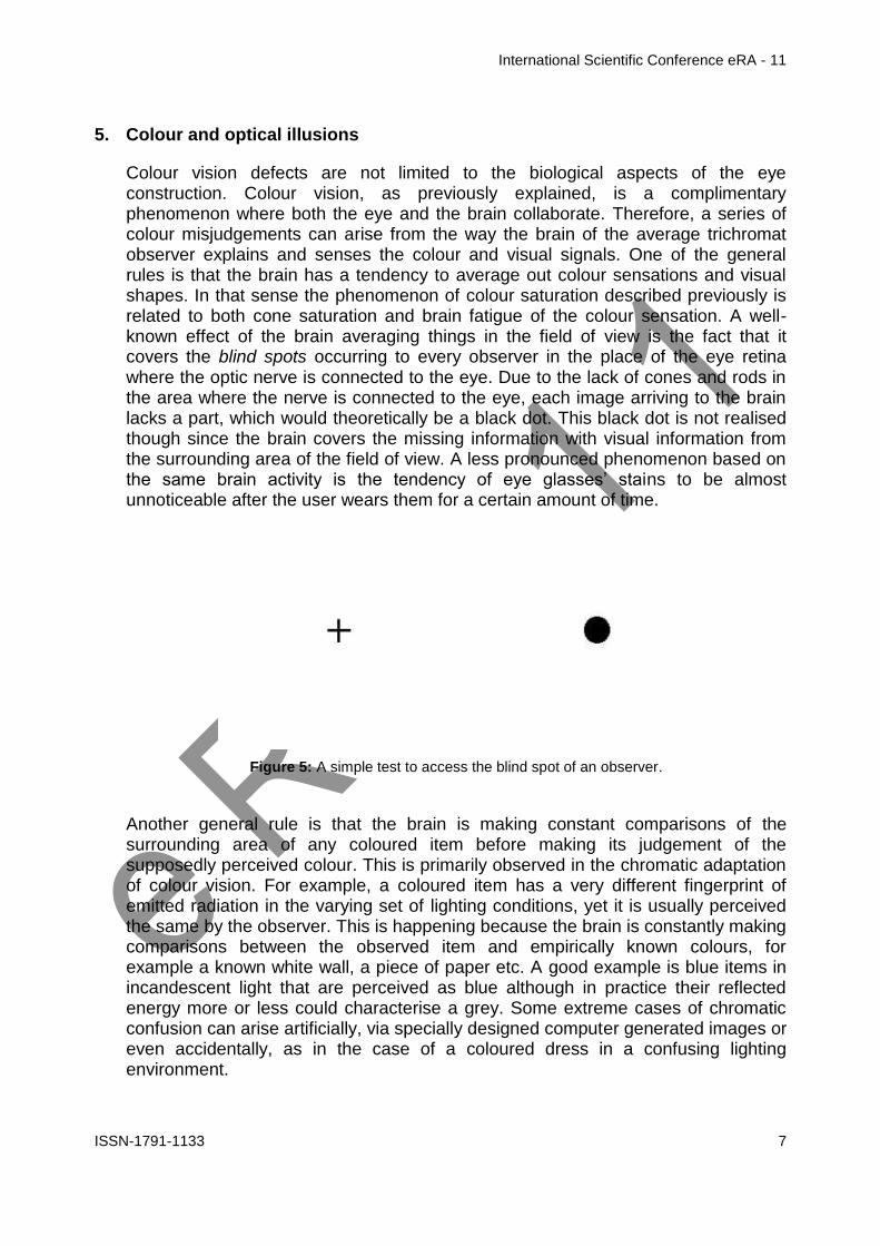
International Scientific Conference eRA - 11
ISSN-1791-1133 12
Comparison study of the technical characteristics of battery energy storage
systems for residential use
M Palyvos 1 GA Vokas2 1 Dpt of Electronics Engineering Piraeus University of Applied Sciences Greece E-mail
mpalivoscosmotemailgr
2 Assoc Professor Dpt of Electronics Engineering Piraeus University of Applied Sciences Greece Tel +30 210 5381180 E-mail gvokasteipirgr
Abstract
One of the major energy issues of our days is reliable and effective energy generation and supply of electricity grids In recent years there has been experienced a rapid development and implementation of Renewable Energy Sources worldwide On one hand many Gigawatts of grid-connected renewables are being installed and on the other many Megawatts of hybrid renewable systems for residential use are being installed making use of electric battery systems in order to cover all daily energy and power needs during New types of batteries are being developed and many companies have made great progress providing a variety of electricity storage products The purpose of this research is firstly to highlight the necessity and also the importance of the use of energy storage systems and secondly through detailed technical simulation analysis using HOMER Pro-optimization software to compare the technical characteristics and performance of energy storage systems by various leading companies when installed in a residential renewable energy system with a specific load Results concerning the operation and the choice of a storage system are derived
1 Introduction
One of the dominant issues of our times pertains to energy and its short-term or long-term use The storage of energy in general and of electricity specifically has become a major issue which needs to be dealt with In order for energy to be stored it is transformed into various forms It can be transformed into Mechanical energy (pumped storage compressed air method flywheels) Chemical energy (Accumulators ndash batteries Flow batteries Hydrogen Accumulators) Magnetic energy (Superconducting Magnetic Energy Storage) Electrical energy (capacitors and supercapacitors) In fig1 the various energy storage technologies are presented
In the past years there has been increased activity with regard to the storage of electrical energy in batteries (Chemical energy)[1-4] This storage method is found to support numerous applications including integration of renewable energy sources transmission deferral frequency regulation peak management etc
International Scientific Conference eRA - 11
ISSN-1791-1133 13
Trends in electrical energy storage systems have to do with the improvement of various cell technologies [5 6] the combination of these storage systems with renewable energy sources [7]
Despite the satisfactory survey has been carried out on the optimization of cell technology and the combination of electrical energy storage systems there is a dark spot on their use on a real residential grid with its daily energy needs
Figure 1 Energy Storage Technologies
This presentation is a culmination of previous research studies and presents the comparative study of an energy storage system for a residential load with the use of batteries by various manufacturers and lists their technical characteristics indicating the optimal system
More specifically in section 2 of this paper the various cell technologies and their technical characteristics as well as specific energy storage systems ndash batteries will be presented and compared Next in section 3 after first describing the load on which the under technical analysis storage system is to be used the various energy storage system configurations will be simulated using ΗΟΜΕR Pro software In addition the technical characteristics of the individual proposed parts of our system shall be listed Finally in section 4 the results will be presented and discussed with analysis of the most dominant scenarios derived by the technical simulation of the energy storage systems by various manufacturers
2 Presentation of various battery cell technologies and systems
This paragraph lists the various battery cell technologies and offers a comparison of such technologies and the technical characteristics of energy storage systems by different manufacturers
21 Battery types-battery cell technologies
The most popular types of batteries are the following
- Lead ndash acid Batteries PbO2
International Scientific Conference eRA - 11
ISSN-1791-1133 14
- Lithium-ion Batteries Li-ion
- Lithium Iron Phosphate Batteries LiFePO4
- Sodium Sulfur Batteries NaS
- Nickel Cadmium Batteries Ni-Cd
- Vanadium-Red Flow Batteries REDOX
22 Main technical characteristics of various cell technologies Lead ndash acid batteries Their energy efficiency ranges from 60- 95 and their self-discharge rate amounts to 2-5 per month Their cycle life ranges between 300 ndash 1500 complete chargedischarge cycles whilst their manufacturing cost is low
Lithium-ion batteries They have significant energy density of 300-400 KWhm3 with an energy efficiency of 90 and a self-discharge rate of 5 per month their cycle life can often reach 10000 complete cycles They have a higher cost compared to other types of batteries
Lithium Iron Phosphate batteries LiFePO4 They have a high number of chargedischarge cycles (6000 cycles) their energy density ranges between 130 ndash 180 KWhm3 with a self-discharge rate of 3 They have a low manufacturing cost
Sodium Sulfur (NaS) Batteries Their energy density amounts to 150-240 kWh m3 and their performance ranges from 75 to 90 They have a relatively high manufacturing cost
Nickel cadmium battery Their energy density amounts to 50-75 kWhm3 and they have a relatively long cycle life of approximately 2000 ndash 2500 chargedischarge cycles Their self-discharge rate ranges from 2-5 whilst they also have a relatively high manufacturing cost
Vanadium redox battery (REDOX) They have low energy density of 16-33kWhm3 and their energy performance ranges from 75 ndash 80 They have a long cycle life of over 12000 chargedischarge cycles whilst their manufacturing cost is low
23 Comparison of technical characteristics of specific batteries This paragraph provides a table featuring the energy storage systems by various manufacturers with their individual technical characteristics
Company Hoppecke
Fenecon
Toshiba
Panasonic
Tesla
Siemens
Samsung
Cell technology
Li-ion
LiFePO4
Li-ion Li-ion Li-ion
Li-ion
Li-ion
Battery capacity (Ah)
154Ah
205Ah
160Ah
167Ah 195Ah
250Ah
200Ah
Nominal Voltage (V)
48V 512V
552V
48V 48V 58V 54V
Storage Capacity (kWh)
74kWh
10kWh
88kWh
8kWh 10kWh
148kWh
108kWh
Chargedischarge cycles
2500
6000
10000
4500 2500
4000
6000
International Scientific Conference eRA - 11
ISSN-1791-1133 15
System Efficiency ()
96 97
90 95 gt92
gt90
96
Operating temperature range(˚C)
(-25)-60
˚C
0-45 ˚C
(-30)-60 ˚C
(-20)-50 ˚C
(-20)-43˚C
(-30)-50˚C
(-10)-40˚C
Battery dimensions (Width-΄Height-Depth) (mm)
612mm467mm242
mm
581mm1270mm60
8mm
359mm123m
m187mm
224mm1380mm966mm
860mm1300mm18
0mm
320mm760mm240mm
280mm1200mm1140mm
Table 1 Technical characteristics of BESS for residential grid
In the above table from manufacturersrsquo data sheets the technical characteristics of all energy storage systems are shown focusing on their performance percentage and their chargedischarge cycles Systems featuring many chargedischarge cycles and a high performance rate are deemed to be the most suitable from a technical point of view for use in various networks
3 Simulation of different hybrid residential energy storage systems
31 Climate and Load profiles
In order to simulate the operational characteristics of various battery types the requirements of a domestic grid in the region of Styra Evoia (38˚96rsquoΝ 24˚142rsquoΕ) with a surface of 108 m2 have been taken into account The load and climate data will be common for all different battery types to be used in order to be able to compare their operation performance under reliably
The temperature and solar radiation data used originate from the National Meteorological Service for the period July 1983 ndash June 2005 As shown in Fig2 the average daily consumption amounts to 1127 kWh deviation is at 10 and the month with the highest electricity requirements is July The peak load hours are 1100 ndash 1400 and 1700-2100
Figure 2 Profile of the residential load
International Scientific Conference eRA - 11
ISSN-1791-1133 16
32 Technical characteristics of proposed equipment
In fig2 the block diagram of a battery energy storage system is shown and in fig3
Figure 2Block diagram of BESS
Figure 3 HOMER block diagram of BESS
The technical characteristics of the proposed battery energy storage system are listed below
- PV generator Mitsubishi single-crystal silicon 250 Watt PV panels connected in strings of 2 with dimensions of 1612101946mm
- Inverter a 5kW Bosch BPT-S 5 Hybrid is used the performance of which reaches 975 with approximately 20 years of life
- MPPT charger (dcdc) A Steca PR 3030 charge controller is used
- Battery type The residential product of 7 different manufacturers (Siemens Toshiba Samsung Hoppecke Fenecon Tesla Panasonic) is chosen
33 Other assumptions The technical analysis simulation and comparison of the energy storage systems will be carried out over 25 years In addition the depth of discharge of each battery energy storage system will not exceed 80 of the nominal capacity of the system
34 Scenarios studied With regard to the residential load cited in a previous paragraph the comparison of technical specifications of the energy storage systems will be based on following three main parameters a) Efficiency b) Cycles to failure at a discharge depth of 80 and c) Mean depth of discharge
4 Results presentation amp Discussion
41 System Efficiency In order to derive results regarding the efficiency of the energy storage systems the HOMER Pro simulation was used and following numerous test and simulations the following results were derived
International Scientific Conference eRA - 11
ISSN-1791-1133 17
Company Stored
Energy (kWhyear)
Energy transmitted to
Grid (kWhyear)
Efficiency
1 Fenecon 22854 22333 9772
2 Hoppecke 23093 22334 9671
3 Samsung 23354 22568 9663
4 Panasonic 22854 21835 9554
5 Tesla 23313 21152 9073
6 Siemens 25174 2284 9072
7 Toshiba 24462 2216 9058
Table 2 Battery Energy Storage System Efficiency
The efficiency of an energy storage system is the ratio of power transmitted to the
grid to stored power 100PowerStored
GridtoPowerdTransmitteEfficiency
Figures 4-10 depict the quantities being compared whilst the efficiency of each BESS is derived from the Energy In and Energy Out values
Energy in refers to the stored power and energy out to the power that is transmitted to the grid The total losses of a storage system are Storage depletion plus systems losses These values are presented on an annual basis and through this procedure the most efficient battery energy storage system is shown
Figure 4 Fenecon BESS
Figure 5 Hoppecke BESS
Figure 6Panasonic Bess
Figure 7 Samsung Bess
Figure 8 Siemens Bess
Figure 9 Tesla Bess
International Scientific Conference eRA - 11
ISSN-1791-1133 18
Figure 10 Toshiba Bess
42 Cycles to failure at a discharge depth of 80
From the data cited on the manufacturersrsquo datasheets on energy storage systems we can derive the results shown in table 3 for the chargedischarge cycles of each system at a discharge depth of 80
Company Depth of
Discharge Cycles to Failure
1 Toshiba 80 10800
2 Samsung 80 7200
3 Fenecon 80 6800
4 Siemens 80 5400
5 Panasonic 80 5000
6 Tesla 80 2500
7 Hoppecke 80 2500
Table 3 Cycles to Failure
43 Mean State of Charge The last axis on which the comparison of the storage systems is based is the mean monthly state of charge which is expressed as a percentage and is a function of the gridrsquos monthly electricity requirements and the storage capacity of such grid
Company Mean Monthly
State of Charge ()
1 Toshiba 7125
2 Samsung 7125
3 Tesla 6958
4 Panasonic 6900
5 Fenecon 6833
6 Siemens 6816
7 Hoppecke 6000
Table 4 Mean Monthly SoC per BESS
The results in the previous table are a product of the simulations as depicted in figures 11-17 which show the mean monthly state of charge
International Scientific Conference eRA - 11
ISSN-1791-1133 19
Figure 11Hoppecke BESS
Figure 12Fenecon BESS
Figure 13Panasonic BESS
Figure 14Samsung BESS
Figure 15Siemens BESS
Figure16Tesla BESS
Figure17Toshiba BESS
5 Conclusions
In the following table 5 the aggregated results of the performed comparisons carried out for 7 different energy storage systems are presented
Company System
Efficiency ()
Cycles to failure (Depth of Discharge
80)
Mean Monthly State of Charge
()
Battery type I 9671 2500 6000
Battery type II
9772 6800 6833
Battery type III
9663 7200 7125
International Scientific Conference eRA - 11
ISSN-1791-1133 20
Battery type IV
9554 5000 6900
Battery type V
9073 5400 6816
Battery type VI
9072 2500 6958
Battery type VII
9058 10800 7125
Table 5 Results of the technical analysis
Based on the results of the simulation an engineer could state with certainty that the system which best meets the requirements of the domestic grid for which the study and simulation were carried out is the one by Battery type VII since over a period of 25 years it is the one with the longest life duration whilst is mean monthly state of charge remains at higher levels compared to the other energy storage systems
On the other hand if the requirement of our grid was for a battery energy storage system with high performance the battery type II would be the most effective choice so this systemrsquos performance should be 9772
Finally after the comparison of the technical characteristics for different battery types through HOMER Pro software the most critical technical characteristics of a BESS are
- Cycles to failure In a lifetime project of more than 15-20 years the most efficient system is the one that provides more cycles of chargedischarge
- State of charge By discharging an energy storage system between 50-70 can be achieved an increase in systemrsquos lifetime
- Efficiency The ability of a battery energy storage system to deliver grid as the largest possible quantity of the stored electric energy is the most critical criterion for the most efficient system
- Other quantities Quantities such as the nominal voltage nominal storage capacity batteryrsquos capacity depend on cell technology and the cell stacks that are assembled to create a battery storage system
References
[1] Gonzaacutelez FD Sumper A Bellmunt OG Robles RV A review of energy storage technologies for wind power applications Renewable and Sustainable Energy Reviews 2012162154-71
[2] Kaldellis JK Zafirakis D Kavadias K Techno-economic comparison of energy storage systems for island autonomous electrical networks Renewable and Sustainable Energy Reviews 200913378-92
[3] Sauer DU Storage Systems for Reliable Future Power Supply Networks In Urban Energy Transition Droege P editor Elsevier 2008
[4] Zafirakis D Overview of energy storage technologies for renewable energy systems In Stand-alone and hybrid wind energy systems technology energy storage and applications Kaldellis JK editor Woodhead Publishing 2010
International Scientific Conference eRA - 11
ISSN-1791-1133 21
[5] Zhang Q Multifunctional separatorinterlayer system fir high stable lithium sulfur batteries Progress amp prospects 2015 Elsevier BV
[6] X-B Cheng C Yan J-Q Huang P Li L Zhu L Zhao Y Zhang W Zhu S-T Yang Q Zhang The gap between long lifespan Li-S coin and pouch cells The importance of lithium metal anode protection 2016 Elsevier BV
[7] Marc Beaudin Hamidreza Zareipour Anthony Schellenberglabe William Rosehart Energy storage for mitigating the variability of renewable electricity sources An updated review 2010 Elsevier BV
[8] Table 3 Cycles to Failure httpwwwtoshibacomticpower-electronicsscib-rechargeable-battery
[9] Table 3 Cycles to failure httpsfenecondepagestromspeicher
[10] Table 3 Cycles to failure httpwwwhoppeckecomenproducttrak-power-lion
[11] Table 3 Cycles to failure httpwwwsiemenscominnovationenhomepictures-of-the-futureenergy-and-efficiencysmart-grids-and-energy-storage-bottled-sunlighthtml
[12] Table 3 Cycles to failure httpwwwsamsungsdicomessindexhtml
[13] Table 3 Cycles to failure httpwwwpanasoniccomauconsumerenergy-solutionsresidential-storage-battery-systemlj-sk84ahtml
[14] Table 3 Cycles to failure httpswwwteslacompowerwall
International Scientific Conference eRA - 11
ISSN-1791-1133 22
Fancy yarns for fashionable fabrics recent developments
Cristina Piroi
Faculty of Textiles - Leather and Industrial Management
Technical University Gheorghe Asachi Iasi Romania Tel +40 232 701143 E-mail cpiroitextuiasiro
Abstract
This paper presents the solutions currently offered by the textile machinery producers
for producing single spun fancy yarns as response to the customersrsquo demands for
spinning machines more flexible highly productive and easy to operate able to
manufacture a large variety of regular or fancy yarns specially designed for particular
applications and affordable
1 Introduction
Manufacture of yarns with a high degree of regularity is one of the most important aims for spinners However for some application a certain degree of irregularity is required to produce fabrics with a particular appearance such as uneven and rough surface that gives the feeling of moving or variations of colour intensity that make the fabrics more interesting for customers The yarns characterised by this kind of desirable lsquodefectsrsquo are known as effect yarns or fancy yarns they contain deliberately introduced irregularities arising from changes in yarn twist andor yarn count (thick or thin places) [1]These yarns are produced by using devices special developed for this purpose that creates discontinuities in yarn structure andor in their colour
During the last several years on the clothing market as well as in the furnishing and home textiles sectors the demands for refined fabrics with more distinguishing features increased continuously Consequently the demand for fancy yarns used for manufacturing new and modern fabrics has grown accordingly Whether used for outerwear home textiles upholstery fabrics or industrial textiles fancy yarns account for an increasing share from the total quantity of yarns produced worldwide
Presently fancy yarns are an essential feature of the modern fashion The denim production is a typical application for fancy yarns In the manufacturing of these fabrics yarns featuring a large numbers of effects are necessary so the ldquofancy denimrdquo effects to be clearly visible in the finished fabric These fancy yarns for denim are characterised by effects with natural appearance which are very similar to natural yarn defects [2]
The development of new types of fancy yarn for fashionable fabrics allows spinners or integrated textile groups to strengthen their relationships with the customers by offering them not only common yarn but also high-quality value-added products [3]
International Scientific Conference eRA - 11
ISSN-1791-1133 23
2 Types of fancy yarns
As a general definition fancy yarns are those yarns in which some deliberate decorative discontinuity or interruption are introduced of either colour or form or of both colour and form These discontinuities are incorporated with the intention of producing an enhanced aesthetic effect In recent years there has been an important increase of the interest in applications of single spun fancy yarns and fancy doubled yarns and these yarns have now a considerable commercial significance Most fancy yarns are produced by specialist fancy spinners using machines modified or developed for the purpose Others are produced from lsquofancy sliversrsquo which are used as minor components in yarns made by spinners using normal equipment [4]
Apart from the fancy doubled yarns which have most often a complex structure consisting of lsquocorersquo threads an lsquoeffect materialrsquo and in the more complex cases a lsquobinderrsquo which holds together the entire structure other types of fancy yarns may be obtained directly on the spinning machines by varying the spinning process conditions
The modern ring-spinning and rotor spinning machines can be equipped with certain devices able to produce single spun fancy yarns The desired effects in yarn are obtained by use of a microprocessor-controlled servomotor system which controls the spinning process This allows change of the rollers speed and consequently of the draft andor the twist enabling thus the creation of yarns with various effects Based on the types of effects introduced the single spun fancy yarns can be grouped into four categories slub yarn multi-count yarn multi-twist yarn and multi-effect yarn
Slub yarn
Slub yarn is the best-known and probably the most frequently used type of fancy yarn A slub yarn is one in which slubs are intentionally created to produce a desired effect Basically the slubs are thick places in the yarn They can be built in form of a gradual change in thickness with only a slight thickening of the yarn followed by its thinning to achieve the base yarn count Alternatively the slub may be three or four times the thickness of the base yarn and that thickness may be achieved for a very short length of yarn [4] Usually the slub yarns are characterised by rather short effects with the length varying between 3 and10 cm
On the ring spinning machine the yarns with slub effect are produced by varying the speed of the middle and back bottom rollers while the speed of the front roller as well as the spindles speed are kept constant This means that the twist per meter in the yarn remains the same (T1=T2) and the yarn are characterised by count
variations with varying twist factor ) (Fig1) [1]
On the rotor spinning machine the slub yarns are produced usually by incorporated electronically-controlled devices that briefly accelerate the feed roller The working principle of these devices is based on the variation of sliver amount supplied into the rotor while the rate of yarn delivered to the bobbin is kept constant However as a result of the doubling action inside the rotor it is not possible to produce slubs shorter than the circumference length of the rotor Any variation in the amount of
International Scientific Conference eRA - 11
ISSN-1791-1133 24
fibres supplied in rotor is spread over a minimum length which is equal to the rotor circumference As example for a rotor diameter of 36 mm the slub effects on rotor spinning machines are at least 113 cm long [1]
Multi-Count yarn
A multi-count yarn is a fancy yarn consisting of lengths of different yarn counts The multicount effect is achieved by controlled changes of yarn thickness on a certain
length while the twist factor is maintained constant ) To obtaining the mass variation along the yarn and create the fancy effects the main draft is periodically reduced through the temporary increases in speed of the back bottom roller and middle bottom roller The twist is adapted to each portion of yarn with different count so the yarn shows a succession of segments with various thickness but with the same twist factor (Fig2)
Figure 1 Slub yarn Figure 2 Multi-count yarn
A multi-count yarn is similar in many respects to slub yarn but due to the modified twist has a higher tenacity in the thin zones In contrast to slub yarn the effects have a longer wavelength giving a special look to the fabrics
Multi-Twist yarn
The fancy yarns with multi-twist effect are produced by applying different twist
factors ) and consequently different twist per meter (T1 T2) to the yarns with constant count (Fig3) These differences in twist creates variations in the yarnrsquos dye intake allowing to obtain fabrics with a special appearance Usually multi-twist yarns are produced with rather long effects of 10-50 cm
The multi-twist fancy yarn is obtained by means of the controlled and accurate acceleration of the front roller The twist variations in the yarn are incorporated by varying the delivery speed of the spinning machine whereas the total draft remains constant
Multi-effect yarn
Multi-effect yarn is a fancy yarn featuring a combination of slub effects multi-count effects and multi-twist effect (Fig4) The variations can be freely programmed in the
case of multi-effect yarn A change in mass can be combined with a twist factor which is not predefined This means that the twist and change in mass in the yarn can be freely selected
Figure 3 Multi-twist yarn Figure 4 Multi-effect yarn
International Scientific Conference eRA - 11
ISSN-1791-1133 25
Lately the fancy yarns obtained on ring-spinning machines and rotor spinning machines have become very popular they and are used most frequently in the denim production for upholstery fabrics and drapes as well as in production of single jersey and fine outerwear fabrics (Fig5)
Figure 5 Various types of fancy yarn fabrics (wwwrhytmfabricscom wwwetsycom)
3 Slub systems for fancy yarns
The Swiss company Amsler Tex provides solutions for production of fancy yarns on all kinds of spinning machines The company cooperates with all important manufacturers of spinning machinery (Marzoli Rieter SchlafhorstZinser Totota
International Scientific Conference eRA - 11
ISSN-1791-1133 26
etc) to develop complete systems for production of fancy yarns as alternative to ordinary yarn on the same machine [5]
Amsler systems are compatible with nearly any type of existing or new ring and open-end spinning frames The devices are installed either with a differential gear or with a direct drive system With the differential gear the creation of the slub is made with an individual slub drive The production of the base yarn is still driven by the basic drive of the spinning machine The high dynamic movement for the slub creation is superimposed through the differential gear This construction enables slub creation without thin places and prevents yarn breakage after a power failure
For the ring spinning frames Amsler provides three types of slub systems the basic slub system the multicountmultitwist system (MCMT) and extreme short slub system (XSS) (Table 1) Figure 6 shows the diagram of Amsler slub device on the ring spinning machine including multi-countmulti-twist function [5]
Amsler ring spinning systems
Minimal slub length
(milimeters)
Maximal number of slubs
(slubsmeter)
Minimul distance between yarn count
change
(meters)
Basic slub 30 10 -
MCMT (incl slub)
30 10 15
XSS 15 - 20 12 - 15 05
Table 1
Figure 6 Diagram of Amsler slub device on ring spinning machine [6]
For open-end frames Amsler Tex offers also three slub systems the standard system the high performance system and the high performance cooling system (Table 2) These systems may be upgraded with the optional multi-count multi-twist function [5]
International Scientific Conference eRA - 11
ISSN-1791-1133 27
Table 2
Figure 7 Working principle of Amsler open-end slub system [5]
Amsler open-end systems Maximum
number of slubs minute
Standard S
TD 150
High performance H
P 200
High performance cooling
HPC
300
All yarn effects produced with Amsler devices are digitally programmed using a dedicated design software Amsler E-Profi is a comprehensive software system for professional slub yarn development and production It has a modular structure and can also include a digital yarn scanner for quality control and slub yarn design [5]
The most comprehensive E-Profi package allows
Advanced creation of slub yarn programs (multicountmultitwist statistics XY yarn preview)
Slub view (analyzing digitized yarn)
Generation of slub yarn programs out of digitized yarn
3D fabric preview (based on weaving and knitting parameters)
Scanner software(laser or flatbed-scanner
During the spinning process the computer controlled drafting system uses the created slub yarn programs to modify the draft in order to obtain the designed fancy yarns
Figure 8 Creating effect yarn [5]
International Scientific Conference eRA - 11
ISSN-1791-1133 28
Figure 9 Designing fashion using E-Profi with fabric preview module [5]
4 Available solutions for producing fancy yarn
Marzoli Fancy Yarn Device
The first manufacturer who introduced a fully integrated device for fancy yarns on its spinning machines was Marzoli in 1999 There are four types of slub effects that can be obtained through continuous variation of the speed of the drafting rollers slub multi-count multi-twist and reverse slub The various combinations among these four slubbing effects can create a large diversity of yarn and fabric designs (Figure 10)
The slub effect is obtained through continuous variations of the main draft by increasing the speed of the back and middle rollers This causes reduction of the main draft and determine the increase of yarn thickness Otherwise to obtain the reverse slub effect the draft variation is negative leading to reductions of the yarn thickness
To design a slub Marzoli system requires setting its length in millimeters its thickness as a percentage of the base yarn (multiplier) and its pause (distance between one slub and the next) in millimeters [6]
Figure 10 Various types of slub yarns [6]
Usually the slubs length is set between 30 to 100 mm but in some cases slubs could be even shorter in order to produce an effect called malfile ie small and frequent slubs that create an effect similar to the natural irregularity of the yarn
The manufacturer claims that Marzoli Fancy Yarn Device is able of producing slubs shorter than 20 mm with up to 20 slubs per meter without compromising the yarn quality and strength by using last generation electronics high efficiency motors
International Scientific Conference eRA - 11
ISSN-1791-1133 29
mechanical transmissions light and solid as well as special acceleration ramps that lasts less than 01 seconds [10]
The multi-count effect is obtained through prolonged variations of the main draft The result is a yarn with different counts along its length Usually this effect is used together with the multi-twist effect in order to obtain interesting effects on fabric
The multi-twist effect entails twist variations that change the yarn diameter its compactness and consequently the behaviour in dyeing This creates interesting lighter and darker areas into the yarn and in the final product
The multi-count and multi-twist effects can be used together to create other interesting effects in fabric In this case the yarn does not have a constant count nor a constat twist For each count is applied a different twist based on selected
constant bdquo rdquo This effect combination is obtained through a variation of the main draft to modify the count and a variation of the front roller speed to modify the twist
Marzoli Fancy Yarn Device is capable of producing fancy yarns of variate forms and designs without requiring any modification to the spinning frame The variation in twist and draft are accomplished by modifying the speed of the independent motors that are already installed on the spinning frame
Rieter VARIOspin Fancy Yarn system
VARIOspin fancy yarn device is the result of cooperation between Rieter AG the supplier of systems for short-staple spinning and AmserTex provider of systems for producing fancy yarns The system is based on the drafting system drive FLEXIdraft which allows separate actuation of the drafting system drives and can be programmed by the user
The feed bottom roller (A) and the center bottom roller (B) are driven by an inverter-controlled motor while the delivery bottom roller (C) is driven separately by another inverter-controlled motor (Fig11) The bottom rollers of the drafting system are independently driven so it can change their rotation speed in accordance with a preset program required to produce a particular yarn effect [7]
Figure 11 FLEXIdraft drafting system drive for fancy yarn production [7]
The slub yarns are obtained by changes in mass effected via the control of the feed bottom roller and the middle bottom roller For an increase in mass they are accelerated thus reducing the total draft For a reduction in mass they are slowed down so total draft is increased To obtain the change in mass without the twist modification the yarn delivery speed and the spindles speed remain constant
International Scientific Conference eRA - 11
ISSN-1791-1133 30
When multi-count yarns and multi-effect yarns are spun changes in mass together with modification of twists per meter are performed all drafting bottom rollers changes their peripheral speed simultaneously in coordination with each other The yarn delivery speed is also changed
Rieters rotor spinning machines can also be equiped with the VARIOspin devices for fancy yarn Any desired effects can be created slub yarns multi-count yarns multi-twist yarns and combined multi-effect yarns The yarn count of the base yarn in fancy yarn spinning is Ne 3 to Ne 40 (Nm 5 to Nm 68) The change in mass of the effect is set in practice at -20 to +400 while twist modification varies between 50 and 150 [2]
More pronounced effects can be achieved by reducing production speed to some extent since a large increase in mass requires more time In principle the draw-off speed for slub sections is the same as for the base yarn However the number of possible effects per unit of time depends on the performance of the feed drive In some cases the delivery speed is reduced for short effects also featuring short spacing [2]
Behind every fancy yarn system there is a program with which the effects can be defined ie programmed The program for Rieter ring-spinning machines is VARIOspinData It enables effect patterns and their repeats to be programmed visualized optimized and managed on the computer (fig11) The formation of a moireacute structure in the fabric caused by a regular effect pattern can be prevented by modifying the program if such a structure is unwantedThe effect patterns created can be transferred to any Rieter ring-spinning machine with a VARIOspin device via a USB stick or optionally via the SPIDERweb data collection system [7]
Figure 11 Programming effects with VARIOspinData [7]
1 - Input of fancy yarn parameters 2 - Visualization of the fancy yarn 3 - Visualization of the yarn surface
International Scientific Conference eRA - 11
ISSN-1791-1133 31
TOYOTA Fancy Yarn Spinning Device
The ring-spinning machines RX300E from Toyota Industries can include optionally the Fancy Yarn Spinning Device that allows manufacture of many types of fancy yarns such as slub yarns multi-count yarns and multi-twist yarns
The operating principle of this device is based on e-Draft System the independently drive system for all three bottom rollers of the drafting systemThese rollers are driven by specialized servo motors which allow setting and changing the speed of each draft roller freely This makes possible slowing down the front roller andor speeding up the back roller in order to produce varied effects in yarn
Types of yarn that can be manufactured on Totota ring-spinning machines RX300E [8]
Positive slub yarn (increase up to 500 comparing the cross-section of base yarn) can be obtained with one of the following options
Front roller deceleration control (with change to twist) Back roller acceleration control (with no change to twist) Combined control of the front and back roller (degree of twist change
can be adjusted)
Negative slub yarn (decrease up to 30 comparing the cross-section of base yarn)
Back roller acceleration control
Multi-count yarn Fixed number of twisted threads (2-6) Fixed number of twists (1-70 twistinch) Any number of twists (1-70 twistinch)
Multi-twist yarn Number of twisted threads 15 - 10
Multi-count+Multi-slub
Slub on slub
Natural slub like
The special developed software Data Creator for Fancy Yarns makes it easy to record and manage the pattern simulations and settings data
Saurer Fancypilot
To meet the demands of a market for fancy yarns with continuous growth the Saurers strategy was initially focused on developing integrated user-friendly solutions for ring and rotor spinning machines Additional mechanical devices were retrofitted to the machine to produce fancy yarns but this approach led to reductions in productivity and also in increases of system complexity
Currently the ring spinning machines Zinser with electronic drafting control system ServoDraft are available for producing fancy yarns both from short-staple and long-staple fibres The draft and the twist can be varied in a controlled manner so slubs of different thickness and lenghts can be introduced in yarn The twist can also be varied for the production of multi-twist yarns and in contrast to previous retrofit solutions now can be spun even yarns with long-wave draft variations [9]
International Scientific Conference eRA - 11
ISSN-1791-1133 32
For rotor spinning machines was developed Fancynation a complete modular system hardware and software fully integrated available both for automatic rotor spinning machines Autocoro and semiautomatic BD machines On the Autocoro 9 this cost-effective option allows to produce up to 5 different fancy yarns simultaneously or fancy yarns and standard yarns in parallel on the same machine [11]
FancyPilot is the software used on the Zinser ring spinning machines and Schlafhorst rotor spinning machines to design fancy yarns The effects are designed managed and controlled on a PC with all design parameters lot and customer data being stored in a database that can be used also in production of standard yarns
5 Conclusion
Although fancy yarns account for only a small proportion of total yarn volume they are in considerable demand depending on fashion trends During the last years the demands for refined fabrics with more distinguishing features increased continuously These fabrics often created by fashion designers provide a higher profit margin when compared with traditional fabrics so more and more spinners are interested to include fancy yarns in their product range
The modern ring-spinning and rotor spinning machines can be equipped with slub devices able to produce single spun fancy yarns The desired effects in yarn are obtained by use of a microprocessor-controlled servomotor system which controls the spinning process There are four basic types of slub effects that can be obtained slub multi-count multi-twist and reverse slub The various combinations among these four slubbing effects can create a large diversity of yarn and fabric designs
The possibility of producing fancy yarns and regular yarns on the same spinning machines by employing new and more advanced integrated slub devices allows to the spinning mills diversifying the range of products without additional running costs as well as strengthen their relationships with the customers
References
[1] R Maier Through thick and thin ndash with Rieterrsquos VARIOspin Link-The customer magazine of Rieter Spun Yarn Systems Vol 22 No 562010 p8-9
[2] M Werner Rotor-spun yarns with fashionable effects for ldquofancy denimrdquo Link-The customer magazine of Rieter Spun Yarn Systems Vol 22 No 562010 p12-13
[3] Amsler-Tex Slub yarn devices for spinning machines httpwwwptjcompk200802-08PDF-February200849-20Spinning20-20Amslerpdf
[4] RH Gong RM Wright Fancy yarns Their manufacture and application Woodhead Publishing Ltd Cambridge England
[5] Technology for textile fashion Brochures of Amsler Tex company [6] Fancy Yarn-Technology for superior flexibility Brochures of Marzoli SpA company [7] R Maier VARIOspin ndash for individual effects in ring-spun and compact yarns Link-The customer
magazine of Rieter Spun Yarn Systems Vol 22 No 562010 p10-11 [8] Ring spinning frame RX300 Brochures of Toyota Company [9] Saurer Fancynation - httpsissuucomoerlikontextilegmbhdocsfancynation [10] httpwwwmarzolicomen [11] httpschlafhorstsaurercomenautocoro-9
International Scientific Conference eRA - 11
ISSN-1791-1133 33
Nonconventional technology for production of decorative cushions
IFilip1 CSava 2 MCiocoiu2 GPriniotakis3
1 SC TAPARO Tg Lapus Romania E-mail ioanfiliptaparoro
2 Textile - Leather amp Industrial Management Faculty ldquoGheorghe Asachirdquo Technical University Iasi Romania
E-mail csavatextuiasiro mciocoiu41yahoocom
3 Textile Department Piraeus University of Applied Sciences Greece gprinteipirgr
Abstract On the market there is a high demand for decorative cushions essential components of the sofas The market are offering lines for the production but at big price and consequently the TAPARO Company Romania propose achieving a production line of decorative cushions with the original conception but with reasonable price For this was used the recovered equipments from cotton spinning mills but and equipment own conception The decorative cushion is from the same material like the sofa and the cushion basket is made of nonwoven textile and filled with a mixture of polyester fiber and polyurethane sticks Maintaining of the cushion geometry for a long time depends on the size and weight of cushion and of the basket of cushion with multiple cells In the paper are presents the changes did on the spinning machines to be used with new function and also achived the machinery of own conception Also in the paper are showed the quality characteristics of the decorative cuchions Keywords fiber polyester polyurethanesticks mixture cushion
1 Introduction
Particularly because of high demand for decorative cushions essential components of the TAPARO Company Romania product the sofas led to the idea of achieving a production line of decorative pillows from original conception considering the high price of identical lines on the market[12] Necessity the production line of decorative cushions was imposed from increased the production of sofas and for another hand of the realization possibility of the line at reasonable price using some of the recovered equipment from cotton spinning technological lines but and equipment own conception Unlike conventional cushion the decorative cushion is from the same material like the cover of sofa and the cushion basket is made of nonwoven textiles and the filling is a mixture of polyester fiber and polyurethane waste Maintaining of the cushion geometry for a long time depends on the size and weight of cushion and of the basket of cushion with multiple cells The mixture of polyester fibers and polyurethane cut waste is an alternative to replace conventional materials in cushions namely -polyester fibre can be fibre at first usage or fibre recovered from nonwoven textiles after cutting panels used in making sofas chairs etc
International Scientific Conference eRA - 11
ISSN-1791-1133 34
-superior utilisation of polyethylene waste with density between 21 to 25 Kgm3 resulting in the process of obtaining components of the sofa - the presence of the polyurethane cut into sticks and individualization polyester fibres in a homogeneous mixture assure good volume and the form of decorative cushions By using polyurethane waste as a component of the mixture forming cushions is assured a significant contribution to maintaining a clean environment Basically best it behaves in a cushion the mixture from silicone polyester fibre 30-32 mm cutting length and density 6-7 dtex and the polyurethane sticks [3]
2 Nonconventional technological line for decorative cushions
Some of the machines from unconventional line were bought from spinning mills mills which were either upgraded or were closed for various reasons These machines have been modified according to the new mode of use and the other part of the equipment from line have been designed and manufactured in the Company TAPARO (figure 1)
Figure1 Schematic unconventional production line of decorative cushions
1 Silicone polyester fibre bales 2 Sack with polyurethane sticks 3 Hopper feeding Trutzschler with weighing 4Opener 5 Condensor Trutzschler 6 Collector conveyor with striking point 7 Transport
ventilator Trutzschler 8 Cleaner with two axial drums Trutzschler 9 Opener Rieter 10Presortat with pressure gauge 11Compressed air pipe 12 Opener Rieter ERM model B5 13 Table for filling cushions 14 Order pedal for filled the cushion 15 Cushions conveyor 16 Electronic balance
17 Sewing machine
3 Made changes on machineries from spinning
Because the line is a succession of machines some of which were used in spinning cotton in what follows will present these changes to equipment and machinery own conception
31Hopper feeding Trutzschler for polyester siliconate fibres
Feeding of fibrous material in the technological process of obtaining decorative cushions is carried with the hopper feeder Trutzschler type KNW [4] (noted 3 in fig 1) who underwent modifications shown in Figures 2 and 3 in comparation with the
International Scientific Conference eRA - 11
ISSN-1791-1133 35
original version The cylinder equalizer is replaced with the lattice equalizer 9 equipped with slats with conic section The space between the lattice equalizer and inclined lattice 10 is at least 4mm thus creating a potent effect of teasing by wresting
Figure 2 Hoppe feeder Trutzschler type KNW with weighing for polyester fiber
1-cylinder with discs 2-photodetector 3- bunker dispenser 4- the superior mobile flap 5 ndash the mobile flap
bunker 6-conveyor 7- main engine (particularly resistant construction to frequent starts) 8- engine driving of
the main engine 9- feeder lattice equalizer 10- spiked lattice
32 Original opener design
Because the the raveling of the fiber tuft in the hopper feeding is insufficient was placed after this a designed an original opener (noted 4 in fig 1) with the cylinder equipped with saw-tooth clothing Thus the raveling of silicon fiber tuft is realized in restraint state The preset quantity of fiber depending on the recipe of mixing falls from basket 1 on the feeder table 2 inclined at 45o Thus it form a fibrous layer pressed by the wood cylinder 3 The gauge between feeder cylinder 4 and feed lattice 2 adjust the material quantity from the dispenser and the thick fibrous layer formed on the feeder lattice The Cylinder 6 has 248 mm diameter is with saw-steel clothing Graff C-55-6
Figure 3 The original opener for the polyester fiber 1 - basket 2 - feeder table 3 - cylinder pressure 4 -cylinder feeder 5- cover feeder cylinder 6- devil
cylinder 7- cover devil cylinder 8 -discharge pipe of individualized fibers 9- grill 10 semi-stiff linear
To achieve an more advanced loosening was fixed to the side walls one semi-stiff lineal 10
International Scientific Conference eRA - 11
ISSN-1791-1133 36
33 Hopper feeder Trutzschler for polyurethane sticks
The supply of polyurethane sticks with the participation quota imposed by recipe is via a same hopper feeder Trutzschler KNW [4] (noted 3 in fig 1) at which were made two key changes - the equalizer role of inclined lattice is canceled - nail bars are replaced with metal scraper
Figure 5 Hopper feeders with inclined lattice with with metal scraper a-side view of hopper feeder1- inclined lattice 2 - plate scraper profile
As shown in fig 5 collecting conveyor table 1 via these scrapers 2 takes the relatively constant quantity of sticks polyurethane and will unloaded its in the feeder Trutzschler KNW
34 Conveyor collector with striking point (noted 6 in fig 1)
Figure 6 Conveyor collector with striking point (noted 6 in fig 1) 1-transport table 2-inclined conveyor 3- opener 4-permanent magnet 5-pipe I- LVS capacitor
I hoper feeder for polyester fibersII-hoper feeders for polyurethane sticks
The conveyor 1 with polyester fibres individualized discharged from the feeder I and with the polyurethane sticks downloaded from the feeder II brings its in the work area of the opener cylinder 3 and conveyor 2 adjusted accordingly with it and take the material ldquosandwichrdquo composed of polyester fibres and polyurethane sticks and pneumatically are conveyed under the permanent magnet 4 and conduit ventilator Trutzschler 425 TV 5
International Scientific Conference eRA - 11
ISSN-1791-1133 37
35 The homogenization of mixture from tow components
The quality of decorative cushions depend of the homogeneity of the mixture of the components fibres polyester and polyurethane sticks to prevent defects (improper filling of the cushions etc) The correct adjustment of feeders ensures the supply adequate quantities of the components but is insufficient for intimate blending To obtain a good mixture were used two machines with the cleaning role in cotton mill which in this technological line provide an intimate mixing of these two components or obtaining a intimate mixture of these two-component in line are used two machines with cleaning and teasing role in cotton mill but which in this case provide intimate mixing of the two components and they are shuffler axial Truschler AXI- FLO and opener Rieter ERM (denoted on fig 1)
351Shuffler axial Trutzschler AXI-FLO
To achieve an intimate mixture between siliconate polyester fibres and polyurethane sticks in the shuffler axial Trutzschler AXI-FLO [4] (noted 8 in fig1) was make the following adjustments -the fan provides the transportation of the mix from two-component with air speed from 12 -15 m s but is advisable using the lower limit of speed to maintain in instalation the mixture more time for enhancing the mixing effect - Bars of grids 5 and 6 were completely closed - Speed drum 3 is 422 rot min left sense of rotation - Rotations drum 4 is 400rot min left sense of rotation - Flap 9 open to positions 78 on the nameplate ensuring for the fibrous material a spiral route about 6-8 tours
Figure 7 Shuffler axial Trutzschler AXI-FLOW 1 supply line 2 screen (damper) 3 4 mixing drums 5 6 grills 7 piece adjustable 8 exhaust pipe
(tubing) 9 flap 10 baffle plate 11 the handle for adjusting the grill 12 waste box 13 observation windows 14 access doors
352Opener Rieter ERM
At the exit of this machine the fibrous mixture two-components is sent to storage to upper chambers 2 (Fig 7) because the simultaneous operation of the four Trutzschler FBK 12 feeders used for filling the cushions ( noted 9 in fig 1) impose keeping constant the amount of material and requires the introduction of some bunker with appropriate storage capacity and with possibility to start and stop the flow depending on mixture consumption (fig 7) For this scope is used the opener
International Scientific Conference eRA - 11
ISSN-1791-1133 38
Rieter B5 5 [5] with a vertical hopper 2 at whose outer wall lamellar 3 allows removing the dust and air At the bottom of the hopper there is a smooth cylinder 6 and a perforated drum 11 that allow the formation of a layer of the mixture over the pair of feeders cylinders 7
Figure 8 Opener Rieter ERM
1- fibers supply line 2- vertical hopper- 3 posterior lamellar wall 4 -pipe exhaust air and dust 5- waste outlet pipe 6- cylinder smooth 7- feed cylinder 8- grill 9- air outlet 10- cylinder with
rigid garnish 11- drum sieve12- pipe for fibrous material evacuation
36 Installation for dosing of the fibrous unconventional mixing
For transportation the unconventional mixture from opener Rieter to each the cushion basket is used a pneumatic installation and 4 feeders Truzschler FBK (noted 12 in fig1) Pneumatic installation ensure uniform filling of the upper bunker of each feeder Truzschler FBK and by through the lower bunker of it assures pneumatic dosing and filling the mixture in the cushion basket
Figure 9 Pneumatic supply system for mixture of polyester fiber -polyurethane sticks 1-Opener Rieter2 Transport ventilator TV 425 3- pipe end 4- pressure control device
5-distribution pipe 6- Trutzschler FBK feeders
To the TrutzschlerFBK feeder have made the following changes 1 The acting of borrowers cylinder 11 it do through a low power motor (035Kw) and a transmission chain 2 During filling hopper lower cylinder debtors11 is stationary their operation is controlled only by the operator The adjustment of amount of mixture is from 100g to 600g
International Scientific Conference eRA - 11
ISSN-1791-1133 39
3 The lower bunker accumulates a quantity of material discharged in 3 to 5 seconds 4 Cylinder feeder 6 receives a stop command to the achievement air pressure in the lower hopper 5 Was replace chute for directing the fibrous layer to the feeder cylinder with a funnel for introducing mixture into the basket cushion 6 Was replace the existing switch (250-350 Pa) with a pressure switch with electronic control for adjusting the air pressure increase beach in the bunker or the quantity of material stored (25 -75 mm Hg water respectively 250-750 Pa) 7 Feeder 6 cylinder receives a stop command to the achievement of predetermined air
37 Installation for filled of the cushion basket
The worker acts the pedal 14 (noted 14 in figure 1) and command the fan and the cylinder 11 (figure 9) and the material is discharged in the cushion basket and the foot must up from the pedal when the pillow is filled then and the cycle repeats Depending on the of number baskets of cushion and it final weight is adjusted f material by some pedal actions that the material from the lower bunker is transferred in cushion basket
4 Results and discussions
41 Checking the accuracy operating of the hoper feeders
To verify the accuracy of operation of the those feeders was realized determinations for the 3 variants of the mixture The taken tests after Rieter opener from 100g 200g and 300g for each variant mixing and realized weightings for each of the two components With the results was calculate the averages and the variation coefficients of thereof In the figure 10 is the histogram of the coefficients of variation for two feeders used for polyester fibre and for polyurethane sticks Is noted that in the case of mixture polyester fibre 100g polyurethane sticks 900g the results are out of recommendations but the average values of the dispensers are very close to those set for each respective dispenser
Figure 10 Histogram of the coefficients of variation of weightings
for each from 2 those feeders
The coefficients of variation are higher for polyester fibre when the quantity of dispenser is below 300g and in case the sticks of polyurethane because sticks table cannot be changed they vary plus or minus from the value set on the scale
International Scientific Conference eRA - 11
ISSN-1791-1133 40
dispenser Also must it is respected provided that the waste polyurethane have close densities between 21-25 [kg m3] [2]
4 2 Checking the function precision of load lines cushions
To verify the accuracy of weighing of the lower hopper of feeders Trutzschler FBK for 3 blends and with different amounts of blended material were carried out randomly set number of determinations For analyze the separation of the two components from the mixture was performed manually and was used the balance Startorius 2354 with an error 001g
With the variation coefficients for the three variants mixing was done a comparative graphical representation as in figure 11
Figure 11 Histogram of the coefficients of variation of cushion mass on blends
For a feeder FBK used in a line for supplying the cards the variation coefficient of linear density of layer fibrous is 115 [3 4] In the case of line production of cushions with non-conventional mixture and the fact that the feeder does not form a continuous fibrous layer he adjusted by feeding amount of the material of the pressure switch the operation is intermittent the coefficient of variation the weighing has values in the range 113 -3 08 and the analysis of the histogram of figure 11 so well below the 5 admitted into the upholstery [1]
5 Conclusions
Originality of the line pneumatic filling of the cushion basket consists in 1 Unlike feeder conventional at the line presented silicone polyester fibre material is subjected to a process of advanced individualization and then using a capacitor is discharged on the conveyor belt 2 For the of polyester fibres was realized a original hoper equipped with cylinder with metallic clothing the operation of individualization is realized in catching condition 3 The feeder Trutzschler doses the quantity of material composed of polyester fibre and polyurethane sticks 4 The main function of shuffler axial Trutzschler Axi FLO is to the mixing of the two components in the airflow 5 The aggregate Rieter has role of feeding mechanism by changing the flow of fibrous material 6 Researchers presented show that unconventional line for product decorative cushions give good results
International Scientific Conference eRA - 11
ISSN-1791-1133 41
References
[1] Scott Forrester ldquoUpholstery Basics Earthrdquo Lodge Publishing Torrington Wyoming 82240 ISBN 978-0-6151-8813-3
[2] Ioan Filip ldquoContributii teoretice şi experimentalela diversificarea producţiei de articole tehnice destinate industriei de tapiţerierdquo Doctoral thesis Iasi 2014
[3] SavaC IchimM bdquoFilatura de bumbacrdquo Iasi Ed Performantica ISBN 973-30-088-2 [4] www Trutzschler com [5] www Rietercom
International Scientific Conference eRA - 11
ISSN-1791-1133 42
The effect of cottonised flax and hemp as eco-friendly substitutes for cotton on the comfort properties of knitted fabrics
M Ichim1 D Făricircmă2 C Sava3 GPriniotakis4
1 Dpt of Engineering and Design of Textile Products ldquoGheorghe Asachirdquo Technical University of Iaşi Iaşi Romania
TelFax +40 232 230491 E-mail michimtextuiasiro
2 Dpt of Engineering of Knitting and Ready-Made Clothing ldquoGheorghe Asachirdquo Technical University of Iaşi Iaşi Romania
TelFax +40 232 230491 E-mail dfarimatextuiasiro
3 Dpt of Engineering and Design of Textile Products ldquoGheorghe Asachirdquo Technical University of Iaşi Iaşi Romania
TelFax +40 232 230491 E-mail csavatextuiasiro
4 Textile Department Piraeus University of Applied Sciences Greece
gprinteipirgr
Abstract
The paper presents the results of a research concerning the effect of partial cotton replacement by cottonised flax and hemp on the comfort properties of knitted fabrics Rotor spun yarns of 59 tex and 100 tex linear density from 30 cottonised flax70 cotton 30 cottonised hemp70 cotton and 100 cotton blends obtained on the cotton spinning system have been used to produce 1 x 1 rib knitted fabrics on a manual flat knitting machine The comfort properties of the knitted fabrics such as porosity air resistance water vapour resistance and thermal resistance have been evaluated Keywords cottonised flax yarn cottonised hemp yarn knitted fabrics comfort properties
1 Introduction
As natural fibres cotton flax and hemp could be considered environmentally
friendly because they are fully biodegradable and renewable raw materials However these criteria alone are not an accurate indicator of their full environmental impact The pollution associated with fibre cultivation and processing must also be taken into consideration in assessing the environmental friendliness of textile products In this respect cotton fibres and products are not considered environmentally-friendly because conventional cotton farming demands substantial amounts of pesticides fungicides herbicides and chemical fertilizers which pollute soil and groundwater Additionally cotton growing requires large amounts of water with negative impact on environment and water resources [1 2] In contrast to cotton flax and hemp are more environmentally friendly Due to its dense foliage higher pest and disease resistance hemp can be grown without the use of
International Scientific Conference eRA - 11
ISSN-1791-1133 43
herbicides pesticides or fungicides and with very little nutrients Even if flax cultivation requires a certain amount of pesticides herbicides and nutrients their levels are much lower than those required for cotton crops Hemp and flax are drought-tolerant requiring only regular rainfall Besides hemp can extract and accumulate heavy metals such as copper lead zinc and cadmium from contaminated soils resulting in soil remediation [3 4]
In contrast to the cotton fibres that are single cells the technical flax and hemp fibres are in the form of bundles of individual cells (elementary fibres) Because the dimensions of the elementary fibres are similar to those of cotton fibres their extraction (called cottonisation) and processing in blends with cotton on the cotton spinning equipment has gained increasing interest [5] When compared to the traditional flax and hemp spinning systems the cotton spinning system is less labour intensive more efficient and more economical
The aim of this research work was to study the effect of partial replacement of the polluting cotton with more eco-friendly fibres as flax and hemp on the comfort properties of the knitted fabrics that come into direct contact with the skin The wear comfort requirements that consumers impose to the apparel producers can be accomplished by the thermo physiological function of clothing The thermo physiological comfort relates to the way clothing dissipates metabolic heat and moisture and depends on many factors such as fibre nature and size yarn type (spun monofilament multifilament textured yarn) fibre and yarn characteristics knitting patterns garment sewing patterns the applied finishing treatments [6]
In this study rotor spun yarns of 59 tex and 100 tex linear density from 30 cottonised flax70 cotton 30 cottonised hemp70 cotton and 100 cotton blends obtained on the cotton spinning system have been used to produce rib knitted fabrics on a manual flat knitting machine The applications of the knitted fabrics are single layer apparel products The comfort characteristics of these apparel products are given solely by the comfort characteristics of the knitted fabrics such as water vapour resistance Rv [mmm2middothg] air resistance Rpa [m2hmmkg] thermal resistance Rt [m2middothoCKcal] and porosity Pz [] Based on the application of the knitted fabrics the comfort requirements that have to be accomplished are as follows low water vapours resistance low air resistance and low thermal resistance
2 Materials and methods
Rotor-spun yarns of 59 tex and 100 tex linear density from cottonised flaxcotton and cottonised hempcotton blends have been obtained on the cotton spinning system using a double carding technology [5] All-cotton yarns of identical linear density were also spun for comparison purpose using standard spinning mill procedures and practices Yarn properties were measured under a standard atmosphere of 20 plusmn 2degC and 65plusmn 2 RH The linear density of yarns has been measured according to SR EN ISO 2060 standard TINIUS OLSEN H5 K-T tensile tester was used to assess the tensile properties of yarns according to EN ISO 2062 standard Twist measurements were performed on a Mesdan twist tester according
International Scientific Conference eRA - 11
ISSN-1791-1133 44
to EN ISO 2061 standard using a clamping distance of 250 mm Yarn mass irregularity was tested on an Uster Tester-II apparatus at a speed of 25 mmin
The properties of rotor yarns are presented in Table 1 As can be seen in Table 1 when compared to 100 cotton yarns of similar linear density the cottonised flaxcotton and cottonised hempcotton blended yarns have lower tenacity lower breaking elongation higher twist and higher irregularity of linear density strength twist and mass The differences between the characteristics of blended yarns containing cottonised flax and hemp and the characteristics of 100 cotton yarns can be explained by the fact that the cottonised flax and hemp fibres are coarser and more variable in fineness than cotton and thus the number of fibres in the cross-section of blended yarns is lower than in the cross-section of all-cotton yarns [7]
Table 1 Yarn properties
Characteristic 30 cottonised flax70 cotton
30 cottonised hemp70 cotton
100 cotton
100 tex 59 tex 100 tex 59 tex 100 tex 59 tex
Linear density tex 102 565 971 575 99 595
CV of linear density 18 34 26 35 14 32
Tenacity cNtex 10 10 903 85 102 104
CV of breaking strength 93 86 157 124 6 8
Breaking elongation 8 56 61 55 8 63
Twist rpm 460 598 470 642 354 459
CV of twist 3 26 2 32 16 23
CVm 161 171 201 186 121 128
The yarns have been converted into 1 x 1 rib knitted fabrics on a manual flat knitting machine characterized by one negative feed system two needle beds and E 10 gauge The obtained variants of knitted fabrics and their course wale and stitch densities are shown in Table 2
Table 2 Knitted fabric variants and course wale and stitch density
Knitted fabric
variant
Fibrous composition Yarn linear
density [tex]
Course density
[courses 5 cm]
Wale density [wales 5 cm]
Stitch density [loops25cm2]
V1 30 cottonised flax 70 cotton 100 tex 48 28 1344
V2 30 cottonised flax 70 cotton 59 tex 43 26 1118
V3 30 cottonised hemp70 cotton 100 tex 45 26 1170
V4 30 cottonised hemp70 cotton 59 tex 45 28 1260
M1 100 cotton 100 tex 55 28 1540
M2 100 cotton 59 tex 48 34 1632
Comfort properties of the knitted fabrics have been tested in laboratory static conditions (63 RH 187degC)
International Scientific Conference eRA - 11
ISSN-1791-1133 45
The knitted fabrics are considered capillary-porous bodies and their porosity can be reported as pore percentage defined as the ratio of pore volume to knitted fabric volume For practical measurement of knitted fabric porosity the picnometric method has been used based on fabric real density and apparent density
The thermal insulation capacity has been expressed as thermal resistance Rt [m2middothmiddotoCKcal] [6]
In order to assess the water vapour transfer through the knitted sample the water vapour resistance Rv [mmm2middothg] has been determined according to STAS 9005-79 standard
The air permeability has been expressed by air resistance Rpa [m2hmmkg] of knitted sample The measurements have been done using a pressure difference of 10 mm of water column according to STAS 5902-70
Twenty individual values for each knitted sample have been averaged in order to obtain de mean value of porosity air resistance water vapour resistance and thermal resistance
3 Results and discussions
The mean values of porosity air resistance water vapour resistance and thermal resistance of the knitted fabrics are presented in Table 3
Table 3 Thermo physiological characteristics and porosity of knitted fabrics
Fabric variant
Pz [ ]
Rv [mmm2middothg]
Rpa [m2hmmKg]
Rt [m2middothmiddotoCKcal
V1 7087 0111 00033 00328
V2 7885 0091 00015 00566
V3 7173 0117 00042 00379
V4 7376 0091 00029 00473
M1 7011 0131 00073 00143
M2 6924 0123 00060 00269
The knitted fabric porosity is a synthetic structural parameter that includes the structural parameters of fibres yarns and knitted fabrics and also the finishing treatments When compared to other textile materials the knitted fabrics have higher porosity Taking into consideration the knitted fabric porosity Pz [] as the main factor that influences the values of the experimentally determined comfort characteristics (water vapour resistance Rv [mmm2middothg] air resistance Rpa [m2hmmkg] thermal resistance Rt [m2middothoCKcal]) their analysis will be done in accordance with the values of porosity Thus as can be seen in Table 3 the knitted fabric variants with content of cottonised flax or cottonised hemp show higher porosities than cotton knitted fabrics This can be explained by the higher bending rigidity and higher twist of blended yarns when compared with cotton yarns and by the lower stitch density of the fabric variants with content of cottonised flax or hemp (Table 2) Even if by cottonisation flax and hemp fibres become softer they are still stiffer than cotton fibres Images of knitted fabrics that exemplify the differences in porosities are presented in Figure 1
International Scientific Conference eRA - 11
ISSN-1791-1133 46
a
b
c
Figure 1 Images of knitted fabrics obtained from 59 tex yarns (4x magnification)
a) 100 cotton b) 30 cottonised flax70 cotton c) 30 cottonised hemp70 cotton
Taking into account the application of the obtained knitted fabrics the comfort requirements that have to be accomplished are as follows low water vapour resistance low air resistance and low thermal resistance
A fabric is comfortable as long as the water vapour released by the skin (perspiration) pass at a fast rate through its pores The results in Table 3 show that the knitted fabrics with content of cottonised flax or hemp offer less resistance to moisture transfer when compared to cotton fabrics This could be due to the fabricsrsquo high moisture absorbency and high porosity
The resistance of a fabric to the flow of air is an important factor in the performance of summer clothes that come into direct contact with the skin The lower the resistance to the air flow the greater the intensity of cooling effect is The results in Table 3 show that cottonised flax and hemp blended fabrics have less resistance to air flow as compared to 100 cotton fabrics and therefore permit more air to pass through This behaviour can be attributed to the higher porosity of these fabrics
The thermal comfort of the body requires equality between the heat produced by the metabolism and the heat lost from the body The resistance of a fabric to the transfer of heat has considerable influence on the comfort of the wearer because determines the rate at which the metabolic heat can be lost The thermal resistance of cottonised flax and hemp blended fabrics measured under dry static conditions is higher than the thermal resistance of 100 cotton fabrics because of the air entrapped in the knitted fabric structure due to the higher porosity However many researchers have found that the environmental air velocity and the water vapour transfer through fabric may cause thermal resistance loss [8 9] Therefore it may be assumed that under dynamic conditions the heat loss through the cottonised flax and hemp blended knitted fabrics is higher than the heat loss through the cotton fabrics due to the lower resistance to air flow and moisture transfer
It may be observed from Table 3 that for all variants of blends an increase in the yarn fineness has as result an increase in the knitted fabric porosity that lead to a reduction of air resistance and water vapour resistance Also an increase in the yarn fineness causes the thermal resistance measured under static dry conditions to increase
International Scientific Conference eRA - 11
ISSN-1791-1133 47
4 Conclusions
Flax and hemp are renewable biodegradable fibres that provide an eco-friendly alternative to conventional cotton which is environmentally destructive Unlike cotton which grows best in warm and moist climate flax and hemp crops grow well in a wide range of climatic conditions and have a considerable potential to develop a bio-based economy
The aim of this research work was to study the effect of partial replacement of cotton with cottonised flax and hemp on the comfort properties of the knitted fabrics that come into direct contact with the skin
Based on the results of this research the following conclusions can be drawn
Adding cottonised flax and hemp to cotton knitted fabrics the water vapour resistance and the air resistance decrease which improve moisture wicking and drying speed This means that moisture is channelled away from the skin surface and the skin is kept cool
Due to the higher porosity of the cottonised flax and hemp blended knitted fabrics their thermal resistance measured under static dry conditions increases when compared to cotton fabrics
The fabrics obtained from finer yarns show lower water vapours resistance and air resistance and higher thermal resistance
References
[1] Chen H-L Burns L D ldquoEnvironmental Analysis of Textile Productsrdquo Clothing amp Textiles Research Journal 24 3 248 2006
[2] Van der Werf H MG Turunen L ldquoThe environmental impacts of the production of hemp and flax textile yarnrdquo Industrial Crops and Products 27 1 2008
[3] Piotrowski S Carus M ldquoEcological benefits of hemp and flax cultivation and productsrdquo Available from httpeihaorgattach64311-05-13_Ecological_benefits_of_hemp_and_flaxpdf Accessed 2016-06-25
[4] Franck R R Bast and other plant fibres Woodhead Publishing Limited Cambridge England 2005
[5] Sava C Ichim M ldquoYarns and Woven Fabrics Made from Cotton and Cottonised Flax Blends for Upholstery Applicationsrdquo Fibres amp Textiles in Eastern Europe 23 5(113) 30-34 2 2015
[6] Farima D ldquoConfortul si functiile produselor textile si din pielerdquo Ed Performantica Iaşi 2008
[7] Sava C Ichim M ldquoHemp ndash an environmentally friendly alternative to cottonrdquo The 15th Romanian Textiles and Leather ConferencendashCORTEP 2014 Poiana Braşov 4 - 6 September pp 57-60 2014
[8] Shekar RI Kotresh TM Subbulakshmi MS Vijaylakshmi SN Prasad ASK ldquoThermal resistance properties of paratrooper clothingrdquo Journal of Industrial Textiles 39(2) 123-148 2009
[9] Ghaddar N Ghali K Jones B ldquoIntegrated human-clothing system model for estimating the effect of walking on clothing insulationrdquo International Journal of Thermal Sciences 42 (6) 605-619 2003
International Scientific Conference eRA - 11
ISSN-1791-1133 48
The influence of the waterproof membrane on the thermal comfort
properties of multi-layer clothing system E Codau
Technical University ldquoGh Asachirdquo Iasi Textile Leather and Industrial Management Faculty Str Prof Dr Doc Dimitrie Mangeron No 28 700050-Iasi Romania
eonofreitextuiasiro
Abstract
In this paper two multi-layer fabric systems intended for firefighters were tested in order to determine the basic parameters of the thermal comfort The thermal comfort was evaluated effectively by measuring the thermal properties of clothing on the sweating guarded hotplate (skin model) The first assembly is composed from the external layer middle layer (thermal insulation) and internal layer (moisture barrier - hydrophilic polyurethane (PU) membrane coated on knitted fabric) The second one contains external layer middle layer (thermal insulation) and an internal layer (liner) Both analysed assemblies contain the same external layer and middle layer
These layers were tested as monolayer and in multi-layer clothing systems The influence of the membrane on the thermal and water-vapour resistance of the multi-layer fabric system was discussed
When the combinations of different materials are used for a multi-layer fabric system the thermal comfort is dependent not only on the properties of each monolayer but also on the manner in which they act together The results showed that the monolayer acting as a moisture barrier has a considerable influence on the overall water-vapour transport abilities The position of the moisture barrier in the assembly is also important in the overall value of water-vapour resistance of the multi-layer system
Keywords moisture barrier hydrophilic polyurethane membrane multi-layer textile system protective clothing resistance of water-vapour Sweating Guarded Hotplate (skin model)
1 Introduction
Various protective clothing (ex for firefighters) and many outdoor sports clothes (ex for cycling running skiing climbing etc) should show excellent barrier properties and at the same time good hygienic characteristics and high comfort of use For these applications waterproof and yet water-vapour permeable (breathable) textiles are state of the art [1] For this purpose membranes with a high effective protection against water air-non-permeable and with high permeability for water-vapour can be used in monolayer or multi-layer clothing system
International Scientific Conference eRA - 11
ISSN-1791-1133 49
Depending on the application and required characteristics of the clothing system the membrane that is its component must also show a suitable set of properties Additional requirements include a low surface weight and thickness low rigidity resistance of the membrane to the conditions of use and washing In some cases (ex protective clothing for firefighters) resistance to heat at elevated temperatures non-flammability and resistance to specific organic solvents are also required [2]
Today a wide range of membranes is available on the market but there are two basic types micro-porous membranes (mostly of a hydrophobic character) and hydrophilic membranes with a compact structure [1 2 3]
The most frequently used polymeric membranes in textile systems include [2]
- hydrophobic microporous polytetrafluoroethylene (PTFE) membranes ex Gore-Tex from the American firm WL Gore amp Assocs Inc - hydrophobic microporous membranes mostly polyurethane ex Porelle membranes of the British firm Porvair - hydrophilic membranes mainly of polyester but also of polyurethane This group includes the familiar polyester materials made by Sympatex Composites Co under the trade name Sympatex as well as polyurethane products BION II from Toyo Cloth
Both principles microporous and hydrophilic can be combined resulting in Bi-component Micro-porous and Hydrophilic Laminates In this case a hydrophilic covering layer is applied to the microporous membrane as realized in Gore-Tex second generation [1]
The microporous membranesacutes pores (002 microm ndash 1 microm) are larger than water-vapour molecules (usually smaller than 00003 microm) which can diffuse through the membrane Capillary mechanism of water-vapour transmition through pores takes place in this case of microporous membrane One the other hand the diameter of water drops (200 microm ndash5000 microm) is higher compared to that of pores of membrane Strong interaction keeps water molecules in a drop preventing their spreading so they are too large to penetrate through the membrane pores (Fig 1 a) [1 3]
Hydrophilic membranes are nonporous and transmit water-vapour by a molecular mechanism The driving force for water-vapour transmission process is a difference in water-vapour pressure between two sides of the membrane which gives rise to a concentration gradient within the membrane [1 3] The water-vapour is first adsorbed on the surface of the membrane on the side of highest water-vapour concentration Water molecules occupy free volume among the molecular chains of polymer and move across the membrane without destroying polymer when penetrating through the membrane with nonporous structure In the case of polymers with active hydrophilic groups water molecules not only fill in the free volume among the polymer molecular chains but also interact with their active hydrophilic groups (Fig 1 b) Due to the moisture gradient they move across the membrane gradually joining the active groups Then they diffuse across by dissolving in the polymer membrane which is usually called as activated diffusion Upon arriving to the opposite surface of the polymer membrane which has a lower vapour pressure it is desorbed and enters the surrounding air space as vapour [3]
International Scientific Conference eRA - 11
ISSN-1791-1133 50
Figure 1 Principle of water-vapour transfer through microporous (a) and hydrophilic (b) membranes (httpwwwsympatexcomenmembrane213performance) [4]
In this paper a hydrophilic PU membrane is tested as a monolayer and in a multi-layer clothing system intended for fire-fighter personal protective equipment (PPE)
Thermal comfort is strongly affected by two intrinsic properties of protective clothing thermal resistance and water-vapour resistance Focus of this study is investigation of these properties of each individual layer and corresponding clothing assemblies using sweating guarded hotplate regarded as the best standardized test method to simulate the heat and mass transfer conditions on a clothed body [5]
The influence of the membrane on the thermal and water-vapour resistance of the multi-layer fabric system is analysed
2 Materials and test methods
21 Fabric materials For this investigation two multi-layer protective clothing structures as the combinations of three monolayers were chosen The first assembly (As1) is composed from the external layer (E) middle layer (M) which is a thermal insulation and internal layer (I_M) which is a moisture barrier respectively The second one (As2) contains external layer (E) middle layer (M) which is a thermal insulation and an internal layer (I_L) which is a liner Both assemblies contain the same external layer and middle layer The internal layer for the first assembly is hydrophilic polyurethane (PU) membrane coated on knitted fabric and for the second assembly a woven fabric In addition another assembly was tested for comparison (As1acute) which was conducted from AS1 but the position of the middle and internal layer was changed between them
International Scientific Conference eRA - 11
ISSN-1791-1133 51
The tested multi-layer assemblies are used as protective clothing for firefighters and are state of the art for firefighter PPE Thus they fit the requirements of EN 4692014 [6] and guarantee a high protection level against fire
22 General physical and thermal comfort properties
Thickness of the monolayers and the multi-layer systems was measured according to the standard ISO 50842013 [7] with the use of a digital thickness gauge from SDL Int Ltd
(England)
Values of materials surface weight were determined by the gravimetric method according to
standard ISO 38012011[8]
Density was calculated from the values of fabric thickness and surface weight
Measurements of thermal and water-vapour resistance of mono- and multi-layer fabrics were conducted on the sweating guarded hotplate in compliance with the standard ISO 110922014 [9] Specific environment testing conditions prescribed by this standard were met using a climatic chamber
The measuring unit of the sweating guarded hotplate possesses both temperature and water supply control According to the standard the procedure for determination of the thermal resistance of material implies the placement of the specimen on an electrically heated porous stainless steel plate with conditioned air conducted to flow across and parallel to its upper surface For the measurement of water-vapour resistance an electrically heated porous plate is covered by water-vapour permeable but liquid-water impermeable membrane Water is supplied by channels beneath the hotplate (measuring unit) can evaporate through the numerous pores of the plate just like sweat from the pores of the skin The hotplate is kept at a temperature of 35degC Thus heat and moisture transport are comparable to those of the human skin Tests for determination of thermal resistance were performed at the ambient conditions of 20plusmn01degC and 65plusmn3RH while the standard conditions for measurement of water-vapour resistance implied 35plusmn01degC and 40plusmn3RH
According to the ISO 110922014 the values of thermal resistance Rct (m2middotKmiddotW-1) and water-vapour resistance Ret (m2middotPamiddotW-1) were calculated using Equations (1) and (2) respectively
ct0
c
amct
)(R
ΔHH
ATTR (1)
et0
e
amet
)(R
ΔHH
AppR (2)
where Tm is the temperature of the measuring unit (degC) Ta the air temperature in the test enclosure (degC) A is the area of the measuring unit (m2) By analogy pm is the saturation water-vapour partial pressure (Pa) at the surface of the measuring unit at temperature Tm and pa is the saturation water-vapour pressure (Pa) of the air in the test enclosure at temperature Ta H is the heating power supplied to the
International Scientific Conference eRA - 11
ISSN-1791-1133 52
measuring unit (W) while ΔHc and ΔHe are the correction terms for heating power (W) for the measurement of thermal resistance Rct and water-vapour resistance Ret respectively Rct0 (m2middotKmiddotW-1) and Ret0 (m2middotPamiddotW-1) are corresponding apparatus constants determined as the ldquobare platerdquo values
In addition to the values of Rct and Ret the monolayers and fabrics assemblies are compared regarding the water-vapour permeability index (imt) as a measure of the material ability to transmit water-vapour from the body It was calculated according to the following equation [9]
et
ctmt
R
RSi (3)
where S is the ratio of Ret and Rct for air a constant equal to 60 PamiddotK-1 The values of the index imt can vary from 0 for an impermeable fabric up to 1 when all the moisture that the ambient environment can take up can pass through the fabric [8]
3 Results and discussion
The composition and the average values of general physical properties of each monolayer and the assemblies along with the corresponding standard deviations are displayed in Table 1
Sample code
Sample Composition
and structure
Surface weight
gmiddotm-2
Density
kgmiddotm-3
Thickness
mm
E External aramid woven fabric 242plusmn2 489plusmn5 050plusmn001
M Middle aramid nonwoven 98plusmn2 67plusmn2 146plusmn003
I_M
Internal
PU coated 100 aramid knitted fabric
195plusmn2 418plusmn6 047plusmn000
I_L aramid woven fabric 150plusmn1 403plusmn6 037plusmn000
As1
Assembly
E+M+I_M 540plusmn4 224plusmn5 240plusmn004
As1` E+I_M+M 540plusmn4 224plusmn5 240plusmn004
As2 E+M+I_L 494plusmn4 218plusmn3 226plusmn003
Table 1 General physical properties of the tested monolayers and assemblies
The thermal and water-vapour resistance average values and their corresponding standard deviations and calculated water-vapour permeability indices are shown in Table 2 It can be noted that the sum of Rct values of individual layers is close to the measured Rct of the assemblies composed of the corresponding layers (Table 2) In contrast with the thermal resistance the total water-vapour resistance of a combination of textiles is not always equal to the sum of the single resistances In
International Scientific Conference eRA - 11
ISSN-1791-1133 53
particular the inclusion of hydrophilic components imparts the complexity of the phenomenon as the water-vapour resistance of these materials depends of the relative humidity of the membrane
Among the monolayers I_M has the highest water-vapour resistance (Ret= 2233 Pamiddotm2middotW-1) It is known that the moisture barrier has powerful impact over the total heat loss of the clothing assembly [10] Considerably higher Ret values of the I_M reflected to high water-vapour resistance of the As1 It confirms the fact that the moisture loss by evaporation is impeded in poorly permeable systems The assembly As2 has no moisture barrier and consequently exhibits the lowest Ret
Sample code
Thermal resistance
(Rct) Ksdotm2sdotW
-1
Σ Rct of monolayers
Ksdotm2sdotW
-1
Water-vapour resistance (Ret)
Pamiddotm2middotW
-1
Σ Ret of monolayers
Ksdotm2sdotW
-1
Water-vapour
permeability index (imt)
E 0013plusmn0009 - 426plusmn027 - 0183
M 0069plusmn0003 - 491plusmn021 - 0843
I_M 0013plusmn0003 - 2233plusmn002 - 0035
I_L 0013plusmn0008 - 254plusmn014 - 0307
As1 0094plusmn0005 0095 2588plusmn004 315 0217
As1` 0096plusmn0006 0095 3545plusmn005 315 0162
As2 0098plusmn0003 0095 1063plusmn006 1171 0558
Table 2 Thermal properties of the tested monolayers and assemblies
The tested multi-layer assemblies As1 and As2 are used as protective clothing for firefighters and are state of the art for firefighter PPE Thus they fit the requirements of EN 4692014 [6] and guarantee a high protection level against fire Within this European Standard two performance levels are given for water-vapour resistance
Level 1- Ref gt 30 Pamiddotm2middotW-1 but not exceeding 45 Pamiddotm2middotW-1
Level 2 ndash Ref lt 30 Pamiddotm2middotW-1
Level 1 is not water-vapour permeable
Both As1 and As2 assemblies correspond the Level 2 and provide good degree of vapour transport
As1 has an acceptable degree of vapour transport but due to the higher water-vapour resistance the comfort properties are reduced and it can lead to a higher risk of steam burns As2 provides the best comfort but its big disadvantage is that it does not provide protection against environmental water
Tests were performed for moister barrier (monolayer) with the membrane placed near the plate (skin) - current position - and with the membrane placed to exterior
International Scientific Conference eRA - 11
ISSN-1791-1133 54
The water-vapour resistance is by 145 lower with the membrane placed near to the plate
Moreover the moisture barrier was placed in different positions in combination as a third layer after thermal liner (As1) and as a second layer between the outer shell and thermal liner (As1acute)
From Table 2 can be noted that the water-vapour resistance of the hydrophilic membrane is lower in combination than alone This result is consistent with other studies [1] If the membrane is quite near to the measuring unit there is comparatively high value of relative humidity and the water-vapour resistance of the hydrophilic component is lower If an additional textile layer is placed between the laminate and the measuring unit some of the water-vapour concentration gradient drops off over that layer and consequently the relative humidity of the membrane is lower than in the first case
The water-vapour resistance of the whole assembly is 27 lower in the combination (As1) that places the membrane close to the measuring unit than in the (As1`) with the membrane placed between other two layers
A remark must be done the tests were done only for water-vapour transfer and not liquid water At the beginning of the human activity the temperature increases and the wearer starts to sweat sensitively but the sweat is evaporating within channels of skin pores and no liquid sweat is produced In this stage the water-vapour resistance of the garments is the most important for comfort During an intense activity a further temperature increase leads to liquid sweat In this stage the buffering capacity of liquid sweat plays a crucial role and the hydrophilic membrane can become more efficiently and gain importance in providing comfort
Water-vapour permeability indices given in Table 2 vary from 0035 for highly impermeable moisture barrier I_M up to 0843 for the thermal insulation M High values of imt for the thermal insulation M are explained by the monolayer low density due to its air capsules The thermal barrier M is a light flexible and breathable product ISOrsquoAIRreg It is a fire and heat resistant nonwoven fabric manufactured with virgin Nomexreg fibres [11]
Among the clothing assemblies the As2 exhibits the highest efficiency of evaporative heat transport having more than two times higher water-vapour permeability index (0558) than the other assembly As1 (0217) According to literature a typical imt value for most permeable clothing ensembles in still air is a bit less than 05 [12]
Hence the assembly As2 has very good comfort properties but great disadvantage of this assembly is its low protection against environmental water As opposed to As2 the low imt value of the As1 that contain a moisture barrier indicates that the release of sweat from the surface of the skin to the atmosphere is reduced and can easily induce discomfort in the conditions of intensive perspiration
International Scientific Conference eRA - 11
ISSN-1791-1133 55
4 Conclusion
The multi-layer fabric systems intended for firefighters were tested in order to determine the basic parameters of the thermal comfort of the wearer The thermal comfort was evaluated effectively by measuring the thermal properties of clothing on the Sweating Guarded Hotplate (skin model) When the combinations of different materials are used for a multi-layer fabric system the thermal comfort is dependent not only on the properties of each monolayer but also on the manner in which they act together The results showed that the monolayer acting as a moisture barrier has a considerable influence on the overall water-vapour transport abilities The position of the moisture barrier in the assembly is also important in the overall value of water-vapour resistance of the multi-layer system
References
[1] VT Bartels ldquoPhysiological comfort of sportswearrdquo In Textiles in Sports Woodhead Publishing Limited ISBN 1-85573-922-4 Cambridge UK 2005
[2] S Brzeziński G Malinowska T Nowak H Schmidt D Marcinkowska A Kaleta ldquoStructure and Properties of Microporous Polyurethane Membranes Designed for Textile-Polymeric Composite Systemsrdquo FIBRES amp TEXTILES in Eastern Europe Vol 13 No 6 (54) pp 53-58 January December 2005
[3] A Gulbinienė V Jankauskaitė V SacevičienėKV Mickus ldquoInvestigation of Water Vapour Resorption Desorption of Textile Laminatesrdquo Materials Science (Medžiagotyra) Vol 13 No 3 pp 255-261 2007
[4] httpwwwsympatexcomenmembrane213performance
[5] R Rossi ldquoInteractions between protection and thermal comfortrdquo in Textiles for Protection Woodhead Publishing Limited ISBN 1-85573-921-6 Cambridge UK 2005
[6] EN 4692014 - Textiles Protective clothing for firefighters Performance requirements for protective clothing for firefighting
[7] ISO 50842013 Textiles -- Determination of thickness of textiles and textile products
[8] ISO 38012011 Textiles -- Woven fabrics -- Determination of mass per unit length and mass per unit area
[9] ISO 110922014 - Textiles -- Physiological effects -- Measurement of thermal and water-vapour resistance under steady-state conditions (sweating guarded-hotplate test)
[10] G Song S Paskaluk R Sati EM Crown JD Dale M Ackerman ldquoThermal protective performance of protective clothing used for low radiant heat protectionrdquo Textile Research Journal
Vol 81 pp 311‑323 2011
[11] httpvidal-protectioncom
[12] RF Goldman ldquoBiomedical Effects of Clothing on Thermal Comfort and Strainrdquo in Handbook on Clothing Biomedical Effects on Military Clothing and Equipment Systems Research Study Group 7 on Bio-medical Research Aspects of Military Protective Clothing 2007
International Scientific Conference eRA - 11
ISSN-1791-1133 56
The Quality of Woven Fabrics as a Hint About the Skirts Quality Designed for
Business Women
Rodica Harpa
ldquoGheorghe Asachirdquo Technical University of Iasi Faculty of Textiles-Leather and Industrial Management 29 D Mangeron Blvd 700050 Iasi Romania
rodica_harpayahoocom
Abstract
This article deals with subjective and objective evaluations of several wool type-woven fabrics with different fibres composition and properties selected by considering the quality profile expected for skirts for business women as a case study for a ready-to-wear pencil skirt collection Regarding the subjective evaluation the activity was conducted on computer-assisted workstations The handle sensations of a team of master students trained according to the AATCC Evaluation Procedure 5-2011 for the primary handle attributes were ldquotranslatedrdquo into experimental results through the fast processing of the STAT-HAND original software In order to make a connection between the subjective evaluation and the objective evaluation the following handle bipolar attributes connected with quality characteristics of the selected fabrics were considered the flexibility stiffness evaluation versus the fabric flexural rigidity measurement the thinness thickness evaluation versus the fabric thickness measurement and the lightness heaviness evaluation versus the fabric weight measurement The research was focused on emphasizing the needs of the customary textile materials selection for specific end-use in garment manufacturing It was also demonstrated that for the appropriate results in the product design should be best to approach both the sensory comfort estimated during the contact with fabric when handled (as a subjective evaluation) and the quality control strategy (as an objective evaluation) As it is a specific niche we expect that business women will select their skirts to match their demands considering fashion quality and last but not least sensorial comfort
1 Introduction
The skirt is considered a very important fashion item in a womans wardrobe and the choice of a particular model depends on many factors among which we can mention the age the activity fashion trends and the price Relevant to choosing and buying skirts is that regardless of the consumer niche targeted the customersrsquo conformation and personality are dominant [1 2] When aiming for the success of a collection on the consumer market the two elements are hard to quantify together [3]
International Scientific Conference eRA - 11
ISSN-1791-1133 57
Regarding the preferences of business women we could expect that this specific niche will select their skirts in order to mainly match their fashion-related demands the quality and last but not least the sensorial comfort demands generated by a simple visualization and handling when purchasing the product [45]
This paper approached both the subjective and objective evaluations of three wool type-woven fabrics with different fibre compositions and properties selected as suitable for the end use considering the quality profile expected for a ready-to-wear pencil skirt collectionrdquo designed for the specific customer niche - business women In order to make a connection between the subjective evaluation grades and the objective evaluation values in this paper we have studied some handle bipolar attributes connected with the quality characteristics of the selected fabrics
2 Experimental part
21 Materials In this paper the entire evaluation (subjective and objective) was carried out for three wool type-woven fabrics with different fibre compositions and properties selected for coating considering the quality profile expected for pencil skirts designed for business women Regarding the color palette of the selected fabrics all of them have been considered as suitable for skirts for daily office attire in any season
Table 1 shows the overall description of the selected fabrics in order to produce the ready-to-wear skirt collectionrdquo for business women
Table 1 Main characteristics of fabrics for the skirts projected for business women
Product
ldquoPencilrdquo Skirts
Fabrics characteristics
Codification F1 F2 F3
Pattern screenshots
International Scientific Conference eRA - 11
ISSN-1791-1133 58
Weaves plain twill 22 twill 21
Yarns characteristics (Warp amp Weft)
Nominal count size Nm 642 Nm 642 Nm 562
Raw material Wool 44PES 54 EL 2
Wool 45PES 55
Wool 44PES 54
EL 2
Density warp10cm 234 338 313
weft10cm 222 288 194
22 Methods The entire study consists of two successive stages in order to emphasize the sensorial comfort features of the selected fabrics according to the designed end use through both subjective and objective evaluation procedures
Subjective evaluation of fabrics selected as coating in skirts intended for business women
The subjective evaluation of fabrics using the sense of touch is a topic in apparels manufacture due to the specificities of the human perception when expressing the sensorial comfort [6 7] According to the AATCC Evaluation Procedure 5-2011 the fabric hand is described as the tactile sensations perceived when fabrics are touched squeezed rubbed or otherwise handled [8]
In Table 2 is shown a linking between specific actions for evaluation of some mechanical and surface properties of fabrics and the bipolar physical attributes in agreement with the main references the Kawabata criteria [9] and the AATCC Evaluation Procedure [8]
Table 2 Handling for the human perception of fabric properties related with sensorial comfort
Actions for evaluation of the mechanical and surface properties
Physical attributes
1 Handling for the evaluation of the tensile properties StretchableNon stretchable
2 Handling for the evaluation of the shear properties Soft Hard
3 Handling for the evaluation of the bending properties Flexible Stiff Crumple-
likeShape recovery
4 Handling for the evaluation of the compression properties Thin Thick
5 Handling for the evaluation of the surface properties Smooth Fuzzy Slippery
Coarse
6 Handling for the evaluation of the weight property Light Heavy
International Scientific Conference eRA - 11
ISSN-1791-1133 59
In order to deploy the subjective evaluation actions for the three woven fabrics hand assessment an evaluator panel with female students (as ldquopotential consumersrdquo) trained to assure a blind evaluation and to quantify their sensorial perceptions during fabrics handling as bipolar attributes according to the AATCC evaluation procedure also defined in the Romanian terminology [8 10] was created
During the blind evaluation all samples of the selected fabrics received grades reflecting the individual perceptions of the evaluators during fabric handling according to a rating scale that quantifies the intensity of each bipolar attribute from 1 to 10 (see Table 3)
Table 3 Evaluation sheet for bipolar attributes
Evaluator Fabric sample
Subjective rating scale
Attribute 1 2 3 4 5 6 7 8 9 10 Attribute
Stretchable Moderately Non stretchable
Soft Moderately Hard
Flexible Moderately Stiff
Thin Thinnest Moderately Thickest Thick
Smooth Moderately Fuzzy
Slippery Moderately Coarse
Light Moderately Heavy
The individual handle sensations of the panel during the blind evaluation were ldquointerpretedrdquo as experimental results by using the STAT-HAND original software
Objective evaluation of fabrics selected as coating in skirts intended for business women
In this second stage of the experimental part the objective evaluation was carried out on the three woven fabrics (shown in Table 1) according to the quality control methodology in the testing laboratory
Considering the results of the subjective evaluation the objective evaluation was performed in the laboratory in order to emphasize the three groups of bipolar attributes which are equivalent with comfort features flexural rigidity thickness and weight measurements
Comparison in terms of similaritydissimilarity between evaluation results of both subjective and objective evaluations
In order to make a connection between both the subjective and the objective evaluations a comparison was carried out between the handle bipolar attributes and the quality characteristics of the three selected fabrics
3 Results and Discussion
Regarding the subjective evaluation the activity was conducted on computer-assisted workstations The handle sensations of the panel of evaluators trained
International Scientific Conference eRA - 11
ISSN-1791-1133 60
according to the AATCC Evaluation Procedure 5-2011 for the primary handle attributes were ldquotranslatedrdquo into experimental results through the fast processing of the STAT-HAND original software [10]
Figure 1 shows the sensory profiles achieved for the three woven fabrics selected as suitable with skirts end use for the business women
Figure 1 Sensory profiles for woven fabrics F1 F2 and F3 after the subjective evaluation
The sensory profiles of fabrics (selected as coating for skirts) after the blind evaluation for the entire panel and based on the average values of the degrees awarded by all evaluators are quite different as are the fabrics
Regarding the assigned grades for the selected bipolar attributes through blind evaluation the results were the following
- FlexibleStiff all three fabrics fall into the high stiffness fabrics category the order of increasing rigidity values being F2 ltF1 ltF3
- ThinThick fabrics F1 and F4 were assessed as thin to moderately and F3 as a fabric thicker than the average the order of increasing thickness values is as follows F1 lt F3ltF2
- LightHeavy fabric F1 was evaluated as a very light fabric and fabrics F2 and F3 were appreciated as fabrics heavier than the average the order of increasing thickness values is as follows F1 lt F2ltF3
The main characteristics of fabrics for the skirts projected for business women are very different from one another through
patterns (plain twill 22 twill 21)
International Scientific Conference eRA - 11
ISSN-1791-1133 61
nominal count size of yarns (Nm 642 Nm 562)
raw material (Wool 44PES 54 EL 2 Wool 45PES 55)
woven yarns density (for both warp and weft)
All these features have created differences between individual assessments but it should be noted that in the end the blind subjective evaluation results confirm the homogeneity of the preparation of the assessorsrsquo panel
Therefore according to the blind assessment results regarding the three bipolar attributes groups and given both destination fabrics and fibrous composition with the fabricsrsquo pattern we can attribute the best sensory comfort for designed end-use to fabric F1 followed by fabric F2
The fabric with the best-evaluated comfort it seems to be F1 made of Wool 44PES 54 EL 2 with a plain pattern with the nominal count size Nm 642 for warp and weft and almost equilibrated yarns density on the warp direction with 234 yarns10cm and on the weft direction with 222 yarns10cm
The experimental part was completed by the comparison of the results obtained after the two stages of evaluation (subjective versus objective) according to the Table 4
Table 4 Comparison between subjective objective evaluation results for the fabrics characteristicsbipolar attributes
Fabric
Subjective evaluation Objective evaluation
Handle attributes
Grades (after blind evaluation)
Characteristics (linked to the handle attributes)
Values
F 1 Flexible Stiff - 8 Flexibility () Stiffness (mg bullcm) 63 57
Thin Thick 2 - Thickness (mm) 036
Light Heavy
3 - Mass per surface unit (gm2)
158
F 2 Flexible Stiff - 7
Flexibility () Stiffness (mg bullcm) 58 107
Thin Thick - 6 Thickness (mm) 049
Light Heavy
- 7 Mass per surface unit (gm2)
210
F 3 Flexible Stiff - 9 Flexibility () Stiffness (mg bullcm) 61 79
Thin Thick 4 - Thickness (mm) 048
Light Heavy - 6 Mass per surface unit (gm2) 220
Analyzing the data in this table we notice that all grades assigned by means of the blind evaluation carried out a ranking of fabrics in terms of comfort sensory are pretty close to that provided by the values obtained from the laboratory testing of the three characteristics linked to the selected handle attributes
4 Conclusion
The research in this manuscript was focused on emphasizing the needs of the customary textile materials selection for specific end-use in garment manufacturing
International Scientific Conference eRA - 11
ISSN-1791-1133 62
Considered a case study the ready-to-wear pencil skirt collection made of three different wool-type fabrics selected as suitable for business women the quality evaluation of the comfort features was completed in two stages deploying first a subjective evaluation and second an objective evaluation
In order to make a connection between the subjective evaluation and the objective evaluation the following handle bipolar attributes connected with quality characteristics of fabrics were considered the flexibility stiffness evaluation versus the fabric flexural rigidity measurement the thinness thickness evaluation versus the fabric thickness measurement and the lightness heaviness evaluation versus the fabric weight measurement
For items of clothing for women in business it is expected that besides the aesthetic criteria (insured in terms of fabrics by pattern and colour) there should be rigorous demands imposed regarding the quality of fabrics which must also include the subjectivity feature of the sensory comfort
With this study it was demonstrated once again that for the appropriate results in the product design it is necessary to approach both the sensory comfort estimated during contact when handling a fabric (as a subjective evaluation) and the quality control strategy (as an objective evaluation)
References
[1] Peirce F The handle of cloth as a measurable quality J Textile Inst 1930
[2] Takako I 2002 Objective Evaluation of the Quality of Ladies Garment Fabrics Textile Research Journal Accessed 01092008
[3] Harpa R Hanganu A 2015 Characteristics of Woven Fabrics for Comfortable Summer Dresses - Subjective and Objective Evaluation 15th Autex World Textile Conference 2015 June 10-12 Book of Abstracts
[4] Sztandera M 2012 Identification of the most significant comfort factors for textiles from processing mechanical hand feel fabric construction and perceived tactile comfort data Textile Research Journal 83 pp 34-43 Accessed 13032013
[5] Hollies NRS 1979 A Human Perception Analysis Approach to Clothing Comfort Textile Research Journal 49 pp 557-564 Accessed 17112011
[6] Ellis BC 1980 A Review of Techniques for the Assessment of Hand Textile Research Journal 50 pp 231-238 Accessed 13032013
[7] Kanai H et al 2011 Identification of principal factors of fabric aesthetics by the evaluation from experts on textiles and from untrained consumers Textile Research Journal 81(12) pp 1216-1225 Accessed 13032013
[8] American Association of Textile Chemists and Colourists 2011 AATCC Evaluation Procedure 5-2011 Fabric Hand Guidelines for the Subjective Evaluation of AATCC Technical Manual
[9] Kawabata S Niwa M Wang F Objective Hand Measurement of Nonwoven Fabrics Part I Development of the Equations Textile Research Journal 64 pp 597-610 1994 Accessed 2011
[10] Harpa R 2016 Fabric Hand Approach by Means of Software Package for Teaching Students Part II Software Applications 12th International Scientific Conference eLearning and Software for Education Bucharest April 21-22 2016 Bucharest Romania April 21 - 22 2016 Volume 3
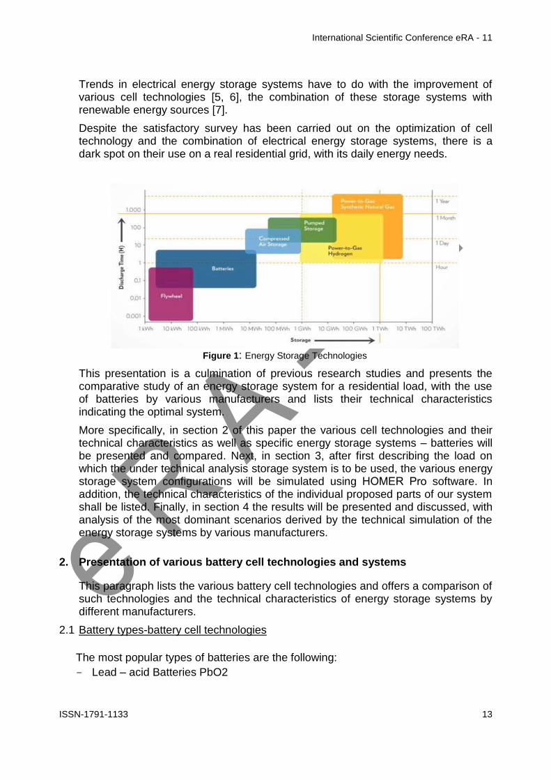
International Scientific Conference eRA - 11
ISSN-1791-1133 14
- Lithium-ion Batteries Li-ion
- Lithium Iron Phosphate Batteries LiFePO4
- Sodium Sulfur Batteries NaS
- Nickel Cadmium Batteries Ni-Cd
- Vanadium-Red Flow Batteries REDOX
22 Main technical characteristics of various cell technologies Lead ndash acid batteries Their energy efficiency ranges from 60- 95 and their self-discharge rate amounts to 2-5 per month Their cycle life ranges between 300 ndash 1500 complete chargedischarge cycles whilst their manufacturing cost is low
Lithium-ion batteries They have significant energy density of 300-400 KWhm3 with an energy efficiency of 90 and a self-discharge rate of 5 per month their cycle life can often reach 10000 complete cycles They have a higher cost compared to other types of batteries
Lithium Iron Phosphate batteries LiFePO4 They have a high number of chargedischarge cycles (6000 cycles) their energy density ranges between 130 ndash 180 KWhm3 with a self-discharge rate of 3 They have a low manufacturing cost
Sodium Sulfur (NaS) Batteries Their energy density amounts to 150-240 kWh m3 and their performance ranges from 75 to 90 They have a relatively high manufacturing cost
Nickel cadmium battery Their energy density amounts to 50-75 kWhm3 and they have a relatively long cycle life of approximately 2000 ndash 2500 chargedischarge cycles Their self-discharge rate ranges from 2-5 whilst they also have a relatively high manufacturing cost
Vanadium redox battery (REDOX) They have low energy density of 16-33kWhm3 and their energy performance ranges from 75 ndash 80 They have a long cycle life of over 12000 chargedischarge cycles whilst their manufacturing cost is low
23 Comparison of technical characteristics of specific batteries This paragraph provides a table featuring the energy storage systems by various manufacturers with their individual technical characteristics
Company Hoppecke
Fenecon
Toshiba
Panasonic
Tesla
Siemens
Samsung
Cell technology
Li-ion
LiFePO4
Li-ion Li-ion Li-ion
Li-ion
Li-ion
Battery capacity (Ah)
154Ah
205Ah
160Ah
167Ah 195Ah
250Ah
200Ah
Nominal Voltage (V)
48V 512V
552V
48V 48V 58V 54V
Storage Capacity (kWh)
74kWh
10kWh
88kWh
8kWh 10kWh
148kWh
108kWh
Chargedischarge cycles
2500
6000
10000
4500 2500
4000
6000
International Scientific Conference eRA - 11
ISSN-1791-1133 15
System Efficiency ()
96 97
90 95 gt92
gt90
96
Operating temperature range(˚C)
(-25)-60
˚C
0-45 ˚C
(-30)-60 ˚C
(-20)-50 ˚C
(-20)-43˚C
(-30)-50˚C
(-10)-40˚C
Battery dimensions (Width-΄Height-Depth) (mm)
612mm467mm242
mm
581mm1270mm60
8mm
359mm123m
m187mm
224mm1380mm966mm
860mm1300mm18
0mm
320mm760mm240mm
280mm1200mm1140mm
Table 1 Technical characteristics of BESS for residential grid
In the above table from manufacturersrsquo data sheets the technical characteristics of all energy storage systems are shown focusing on their performance percentage and their chargedischarge cycles Systems featuring many chargedischarge cycles and a high performance rate are deemed to be the most suitable from a technical point of view for use in various networks
3 Simulation of different hybrid residential energy storage systems
31 Climate and Load profiles
In order to simulate the operational characteristics of various battery types the requirements of a domestic grid in the region of Styra Evoia (38˚96rsquoΝ 24˚142rsquoΕ) with a surface of 108 m2 have been taken into account The load and climate data will be common for all different battery types to be used in order to be able to compare their operation performance under reliably
The temperature and solar radiation data used originate from the National Meteorological Service for the period July 1983 ndash June 2005 As shown in Fig2 the average daily consumption amounts to 1127 kWh deviation is at 10 and the month with the highest electricity requirements is July The peak load hours are 1100 ndash 1400 and 1700-2100
Figure 2 Profile of the residential load
International Scientific Conference eRA - 11
ISSN-1791-1133 16
32 Technical characteristics of proposed equipment
In fig2 the block diagram of a battery energy storage system is shown and in fig3
Figure 2Block diagram of BESS
Figure 3 HOMER block diagram of BESS
The technical characteristics of the proposed battery energy storage system are listed below
- PV generator Mitsubishi single-crystal silicon 250 Watt PV panels connected in strings of 2 with dimensions of 1612101946mm
- Inverter a 5kW Bosch BPT-S 5 Hybrid is used the performance of which reaches 975 with approximately 20 years of life
- MPPT charger (dcdc) A Steca PR 3030 charge controller is used
- Battery type The residential product of 7 different manufacturers (Siemens Toshiba Samsung Hoppecke Fenecon Tesla Panasonic) is chosen
33 Other assumptions The technical analysis simulation and comparison of the energy storage systems will be carried out over 25 years In addition the depth of discharge of each battery energy storage system will not exceed 80 of the nominal capacity of the system
34 Scenarios studied With regard to the residential load cited in a previous paragraph the comparison of technical specifications of the energy storage systems will be based on following three main parameters a) Efficiency b) Cycles to failure at a discharge depth of 80 and c) Mean depth of discharge
4 Results presentation amp Discussion
41 System Efficiency In order to derive results regarding the efficiency of the energy storage systems the HOMER Pro simulation was used and following numerous test and simulations the following results were derived
International Scientific Conference eRA - 11
ISSN-1791-1133 17
Company Stored
Energy (kWhyear)
Energy transmitted to
Grid (kWhyear)
Efficiency
1 Fenecon 22854 22333 9772
2 Hoppecke 23093 22334 9671
3 Samsung 23354 22568 9663
4 Panasonic 22854 21835 9554
5 Tesla 23313 21152 9073
6 Siemens 25174 2284 9072
7 Toshiba 24462 2216 9058
Table 2 Battery Energy Storage System Efficiency
The efficiency of an energy storage system is the ratio of power transmitted to the
grid to stored power 100PowerStored
GridtoPowerdTransmitteEfficiency
Figures 4-10 depict the quantities being compared whilst the efficiency of each BESS is derived from the Energy In and Energy Out values
Energy in refers to the stored power and energy out to the power that is transmitted to the grid The total losses of a storage system are Storage depletion plus systems losses These values are presented on an annual basis and through this procedure the most efficient battery energy storage system is shown
Figure 4 Fenecon BESS
Figure 5 Hoppecke BESS
Figure 6Panasonic Bess
Figure 7 Samsung Bess
Figure 8 Siemens Bess
Figure 9 Tesla Bess
International Scientific Conference eRA - 11
ISSN-1791-1133 18
Figure 10 Toshiba Bess
42 Cycles to failure at a discharge depth of 80
From the data cited on the manufacturersrsquo datasheets on energy storage systems we can derive the results shown in table 3 for the chargedischarge cycles of each system at a discharge depth of 80
Company Depth of
Discharge Cycles to Failure
1 Toshiba 80 10800
2 Samsung 80 7200
3 Fenecon 80 6800
4 Siemens 80 5400
5 Panasonic 80 5000
6 Tesla 80 2500
7 Hoppecke 80 2500
Table 3 Cycles to Failure
43 Mean State of Charge The last axis on which the comparison of the storage systems is based is the mean monthly state of charge which is expressed as a percentage and is a function of the gridrsquos monthly electricity requirements and the storage capacity of such grid
Company Mean Monthly
State of Charge ()
1 Toshiba 7125
2 Samsung 7125
3 Tesla 6958
4 Panasonic 6900
5 Fenecon 6833
6 Siemens 6816
7 Hoppecke 6000
Table 4 Mean Monthly SoC per BESS
The results in the previous table are a product of the simulations as depicted in figures 11-17 which show the mean monthly state of charge
International Scientific Conference eRA - 11
ISSN-1791-1133 19
Figure 11Hoppecke BESS
Figure 12Fenecon BESS
Figure 13Panasonic BESS
Figure 14Samsung BESS
Figure 15Siemens BESS
Figure16Tesla BESS
Figure17Toshiba BESS
5 Conclusions
In the following table 5 the aggregated results of the performed comparisons carried out for 7 different energy storage systems are presented
Company System
Efficiency ()
Cycles to failure (Depth of Discharge
80)
Mean Monthly State of Charge
()
Battery type I 9671 2500 6000
Battery type II
9772 6800 6833
Battery type III
9663 7200 7125
International Scientific Conference eRA - 11
ISSN-1791-1133 20
Battery type IV
9554 5000 6900
Battery type V
9073 5400 6816
Battery type VI
9072 2500 6958
Battery type VII
9058 10800 7125
Table 5 Results of the technical analysis
Based on the results of the simulation an engineer could state with certainty that the system which best meets the requirements of the domestic grid for which the study and simulation were carried out is the one by Battery type VII since over a period of 25 years it is the one with the longest life duration whilst is mean monthly state of charge remains at higher levels compared to the other energy storage systems
On the other hand if the requirement of our grid was for a battery energy storage system with high performance the battery type II would be the most effective choice so this systemrsquos performance should be 9772
Finally after the comparison of the technical characteristics for different battery types through HOMER Pro software the most critical technical characteristics of a BESS are
- Cycles to failure In a lifetime project of more than 15-20 years the most efficient system is the one that provides more cycles of chargedischarge
- State of charge By discharging an energy storage system between 50-70 can be achieved an increase in systemrsquos lifetime
- Efficiency The ability of a battery energy storage system to deliver grid as the largest possible quantity of the stored electric energy is the most critical criterion for the most efficient system
- Other quantities Quantities such as the nominal voltage nominal storage capacity batteryrsquos capacity depend on cell technology and the cell stacks that are assembled to create a battery storage system
References
[1] Gonzaacutelez FD Sumper A Bellmunt OG Robles RV A review of energy storage technologies for wind power applications Renewable and Sustainable Energy Reviews 2012162154-71
[2] Kaldellis JK Zafirakis D Kavadias K Techno-economic comparison of energy storage systems for island autonomous electrical networks Renewable and Sustainable Energy Reviews 200913378-92
[3] Sauer DU Storage Systems for Reliable Future Power Supply Networks In Urban Energy Transition Droege P editor Elsevier 2008
[4] Zafirakis D Overview of energy storage technologies for renewable energy systems In Stand-alone and hybrid wind energy systems technology energy storage and applications Kaldellis JK editor Woodhead Publishing 2010
International Scientific Conference eRA - 11
ISSN-1791-1133 21
[5] Zhang Q Multifunctional separatorinterlayer system fir high stable lithium sulfur batteries Progress amp prospects 2015 Elsevier BV
[6] X-B Cheng C Yan J-Q Huang P Li L Zhu L Zhao Y Zhang W Zhu S-T Yang Q Zhang The gap between long lifespan Li-S coin and pouch cells The importance of lithium metal anode protection 2016 Elsevier BV
[7] Marc Beaudin Hamidreza Zareipour Anthony Schellenberglabe William Rosehart Energy storage for mitigating the variability of renewable electricity sources An updated review 2010 Elsevier BV
[8] Table 3 Cycles to Failure httpwwwtoshibacomticpower-electronicsscib-rechargeable-battery
[9] Table 3 Cycles to failure httpsfenecondepagestromspeicher
[10] Table 3 Cycles to failure httpwwwhoppeckecomenproducttrak-power-lion
[11] Table 3 Cycles to failure httpwwwsiemenscominnovationenhomepictures-of-the-futureenergy-and-efficiencysmart-grids-and-energy-storage-bottled-sunlighthtml
[12] Table 3 Cycles to failure httpwwwsamsungsdicomessindexhtml
[13] Table 3 Cycles to failure httpwwwpanasoniccomauconsumerenergy-solutionsresidential-storage-battery-systemlj-sk84ahtml
[14] Table 3 Cycles to failure httpswwwteslacompowerwall
International Scientific Conference eRA - 11
ISSN-1791-1133 22
Fancy yarns for fashionable fabrics recent developments
Cristina Piroi
Faculty of Textiles - Leather and Industrial Management
Technical University Gheorghe Asachi Iasi Romania Tel +40 232 701143 E-mail cpiroitextuiasiro
Abstract
This paper presents the solutions currently offered by the textile machinery producers
for producing single spun fancy yarns as response to the customersrsquo demands for
spinning machines more flexible highly productive and easy to operate able to
manufacture a large variety of regular or fancy yarns specially designed for particular
applications and affordable
1 Introduction
Manufacture of yarns with a high degree of regularity is one of the most important aims for spinners However for some application a certain degree of irregularity is required to produce fabrics with a particular appearance such as uneven and rough surface that gives the feeling of moving or variations of colour intensity that make the fabrics more interesting for customers The yarns characterised by this kind of desirable lsquodefectsrsquo are known as effect yarns or fancy yarns they contain deliberately introduced irregularities arising from changes in yarn twist andor yarn count (thick or thin places) [1]These yarns are produced by using devices special developed for this purpose that creates discontinuities in yarn structure andor in their colour
During the last several years on the clothing market as well as in the furnishing and home textiles sectors the demands for refined fabrics with more distinguishing features increased continuously Consequently the demand for fancy yarns used for manufacturing new and modern fabrics has grown accordingly Whether used for outerwear home textiles upholstery fabrics or industrial textiles fancy yarns account for an increasing share from the total quantity of yarns produced worldwide
Presently fancy yarns are an essential feature of the modern fashion The denim production is a typical application for fancy yarns In the manufacturing of these fabrics yarns featuring a large numbers of effects are necessary so the ldquofancy denimrdquo effects to be clearly visible in the finished fabric These fancy yarns for denim are characterised by effects with natural appearance which are very similar to natural yarn defects [2]
The development of new types of fancy yarn for fashionable fabrics allows spinners or integrated textile groups to strengthen their relationships with the customers by offering them not only common yarn but also high-quality value-added products [3]
International Scientific Conference eRA - 11
ISSN-1791-1133 23
2 Types of fancy yarns
As a general definition fancy yarns are those yarns in which some deliberate decorative discontinuity or interruption are introduced of either colour or form or of both colour and form These discontinuities are incorporated with the intention of producing an enhanced aesthetic effect In recent years there has been an important increase of the interest in applications of single spun fancy yarns and fancy doubled yarns and these yarns have now a considerable commercial significance Most fancy yarns are produced by specialist fancy spinners using machines modified or developed for the purpose Others are produced from lsquofancy sliversrsquo which are used as minor components in yarns made by spinners using normal equipment [4]
Apart from the fancy doubled yarns which have most often a complex structure consisting of lsquocorersquo threads an lsquoeffect materialrsquo and in the more complex cases a lsquobinderrsquo which holds together the entire structure other types of fancy yarns may be obtained directly on the spinning machines by varying the spinning process conditions
The modern ring-spinning and rotor spinning machines can be equipped with certain devices able to produce single spun fancy yarns The desired effects in yarn are obtained by use of a microprocessor-controlled servomotor system which controls the spinning process This allows change of the rollers speed and consequently of the draft andor the twist enabling thus the creation of yarns with various effects Based on the types of effects introduced the single spun fancy yarns can be grouped into four categories slub yarn multi-count yarn multi-twist yarn and multi-effect yarn
Slub yarn
Slub yarn is the best-known and probably the most frequently used type of fancy yarn A slub yarn is one in which slubs are intentionally created to produce a desired effect Basically the slubs are thick places in the yarn They can be built in form of a gradual change in thickness with only a slight thickening of the yarn followed by its thinning to achieve the base yarn count Alternatively the slub may be three or four times the thickness of the base yarn and that thickness may be achieved for a very short length of yarn [4] Usually the slub yarns are characterised by rather short effects with the length varying between 3 and10 cm
On the ring spinning machine the yarns with slub effect are produced by varying the speed of the middle and back bottom rollers while the speed of the front roller as well as the spindles speed are kept constant This means that the twist per meter in the yarn remains the same (T1=T2) and the yarn are characterised by count
variations with varying twist factor ) (Fig1) [1]
On the rotor spinning machine the slub yarns are produced usually by incorporated electronically-controlled devices that briefly accelerate the feed roller The working principle of these devices is based on the variation of sliver amount supplied into the rotor while the rate of yarn delivered to the bobbin is kept constant However as a result of the doubling action inside the rotor it is not possible to produce slubs shorter than the circumference length of the rotor Any variation in the amount of
International Scientific Conference eRA - 11
ISSN-1791-1133 24
fibres supplied in rotor is spread over a minimum length which is equal to the rotor circumference As example for a rotor diameter of 36 mm the slub effects on rotor spinning machines are at least 113 cm long [1]
Multi-Count yarn
A multi-count yarn is a fancy yarn consisting of lengths of different yarn counts The multicount effect is achieved by controlled changes of yarn thickness on a certain
length while the twist factor is maintained constant ) To obtaining the mass variation along the yarn and create the fancy effects the main draft is periodically reduced through the temporary increases in speed of the back bottom roller and middle bottom roller The twist is adapted to each portion of yarn with different count so the yarn shows a succession of segments with various thickness but with the same twist factor (Fig2)
Figure 1 Slub yarn Figure 2 Multi-count yarn
A multi-count yarn is similar in many respects to slub yarn but due to the modified twist has a higher tenacity in the thin zones In contrast to slub yarn the effects have a longer wavelength giving a special look to the fabrics
Multi-Twist yarn
The fancy yarns with multi-twist effect are produced by applying different twist
factors ) and consequently different twist per meter (T1 T2) to the yarns with constant count (Fig3) These differences in twist creates variations in the yarnrsquos dye intake allowing to obtain fabrics with a special appearance Usually multi-twist yarns are produced with rather long effects of 10-50 cm
The multi-twist fancy yarn is obtained by means of the controlled and accurate acceleration of the front roller The twist variations in the yarn are incorporated by varying the delivery speed of the spinning machine whereas the total draft remains constant
Multi-effect yarn
Multi-effect yarn is a fancy yarn featuring a combination of slub effects multi-count effects and multi-twist effect (Fig4) The variations can be freely programmed in the
case of multi-effect yarn A change in mass can be combined with a twist factor which is not predefined This means that the twist and change in mass in the yarn can be freely selected
Figure 3 Multi-twist yarn Figure 4 Multi-effect yarn
International Scientific Conference eRA - 11
ISSN-1791-1133 25
Lately the fancy yarns obtained on ring-spinning machines and rotor spinning machines have become very popular they and are used most frequently in the denim production for upholstery fabrics and drapes as well as in production of single jersey and fine outerwear fabrics (Fig5)
Figure 5 Various types of fancy yarn fabrics (wwwrhytmfabricscom wwwetsycom)
3 Slub systems for fancy yarns
The Swiss company Amsler Tex provides solutions for production of fancy yarns on all kinds of spinning machines The company cooperates with all important manufacturers of spinning machinery (Marzoli Rieter SchlafhorstZinser Totota
International Scientific Conference eRA - 11
ISSN-1791-1133 26
etc) to develop complete systems for production of fancy yarns as alternative to ordinary yarn on the same machine [5]
Amsler systems are compatible with nearly any type of existing or new ring and open-end spinning frames The devices are installed either with a differential gear or with a direct drive system With the differential gear the creation of the slub is made with an individual slub drive The production of the base yarn is still driven by the basic drive of the spinning machine The high dynamic movement for the slub creation is superimposed through the differential gear This construction enables slub creation without thin places and prevents yarn breakage after a power failure
For the ring spinning frames Amsler provides three types of slub systems the basic slub system the multicountmultitwist system (MCMT) and extreme short slub system (XSS) (Table 1) Figure 6 shows the diagram of Amsler slub device on the ring spinning machine including multi-countmulti-twist function [5]
Amsler ring spinning systems
Minimal slub length
(milimeters)
Maximal number of slubs
(slubsmeter)
Minimul distance between yarn count
change
(meters)
Basic slub 30 10 -
MCMT (incl slub)
30 10 15
XSS 15 - 20 12 - 15 05
Table 1
Figure 6 Diagram of Amsler slub device on ring spinning machine [6]
For open-end frames Amsler Tex offers also three slub systems the standard system the high performance system and the high performance cooling system (Table 2) These systems may be upgraded with the optional multi-count multi-twist function [5]
International Scientific Conference eRA - 11
ISSN-1791-1133 27
Table 2
Figure 7 Working principle of Amsler open-end slub system [5]
Amsler open-end systems Maximum
number of slubs minute
Standard S
TD 150
High performance H
P 200
High performance cooling
HPC
300
All yarn effects produced with Amsler devices are digitally programmed using a dedicated design software Amsler E-Profi is a comprehensive software system for professional slub yarn development and production It has a modular structure and can also include a digital yarn scanner for quality control and slub yarn design [5]
The most comprehensive E-Profi package allows
Advanced creation of slub yarn programs (multicountmultitwist statistics XY yarn preview)
Slub view (analyzing digitized yarn)
Generation of slub yarn programs out of digitized yarn
3D fabric preview (based on weaving and knitting parameters)
Scanner software(laser or flatbed-scanner
During the spinning process the computer controlled drafting system uses the created slub yarn programs to modify the draft in order to obtain the designed fancy yarns
Figure 8 Creating effect yarn [5]
International Scientific Conference eRA - 11
ISSN-1791-1133 28
Figure 9 Designing fashion using E-Profi with fabric preview module [5]
4 Available solutions for producing fancy yarn
Marzoli Fancy Yarn Device
The first manufacturer who introduced a fully integrated device for fancy yarns on its spinning machines was Marzoli in 1999 There are four types of slub effects that can be obtained through continuous variation of the speed of the drafting rollers slub multi-count multi-twist and reverse slub The various combinations among these four slubbing effects can create a large diversity of yarn and fabric designs (Figure 10)
The slub effect is obtained through continuous variations of the main draft by increasing the speed of the back and middle rollers This causes reduction of the main draft and determine the increase of yarn thickness Otherwise to obtain the reverse slub effect the draft variation is negative leading to reductions of the yarn thickness
To design a slub Marzoli system requires setting its length in millimeters its thickness as a percentage of the base yarn (multiplier) and its pause (distance between one slub and the next) in millimeters [6]
Figure 10 Various types of slub yarns [6]
Usually the slubs length is set between 30 to 100 mm but in some cases slubs could be even shorter in order to produce an effect called malfile ie small and frequent slubs that create an effect similar to the natural irregularity of the yarn
The manufacturer claims that Marzoli Fancy Yarn Device is able of producing slubs shorter than 20 mm with up to 20 slubs per meter without compromising the yarn quality and strength by using last generation electronics high efficiency motors
International Scientific Conference eRA - 11
ISSN-1791-1133 29
mechanical transmissions light and solid as well as special acceleration ramps that lasts less than 01 seconds [10]
The multi-count effect is obtained through prolonged variations of the main draft The result is a yarn with different counts along its length Usually this effect is used together with the multi-twist effect in order to obtain interesting effects on fabric
The multi-twist effect entails twist variations that change the yarn diameter its compactness and consequently the behaviour in dyeing This creates interesting lighter and darker areas into the yarn and in the final product
The multi-count and multi-twist effects can be used together to create other interesting effects in fabric In this case the yarn does not have a constant count nor a constat twist For each count is applied a different twist based on selected
constant bdquo rdquo This effect combination is obtained through a variation of the main draft to modify the count and a variation of the front roller speed to modify the twist
Marzoli Fancy Yarn Device is capable of producing fancy yarns of variate forms and designs without requiring any modification to the spinning frame The variation in twist and draft are accomplished by modifying the speed of the independent motors that are already installed on the spinning frame
Rieter VARIOspin Fancy Yarn system
VARIOspin fancy yarn device is the result of cooperation between Rieter AG the supplier of systems for short-staple spinning and AmserTex provider of systems for producing fancy yarns The system is based on the drafting system drive FLEXIdraft which allows separate actuation of the drafting system drives and can be programmed by the user
The feed bottom roller (A) and the center bottom roller (B) are driven by an inverter-controlled motor while the delivery bottom roller (C) is driven separately by another inverter-controlled motor (Fig11) The bottom rollers of the drafting system are independently driven so it can change their rotation speed in accordance with a preset program required to produce a particular yarn effect [7]
Figure 11 FLEXIdraft drafting system drive for fancy yarn production [7]
The slub yarns are obtained by changes in mass effected via the control of the feed bottom roller and the middle bottom roller For an increase in mass they are accelerated thus reducing the total draft For a reduction in mass they are slowed down so total draft is increased To obtain the change in mass without the twist modification the yarn delivery speed and the spindles speed remain constant
International Scientific Conference eRA - 11
ISSN-1791-1133 30
When multi-count yarns and multi-effect yarns are spun changes in mass together with modification of twists per meter are performed all drafting bottom rollers changes their peripheral speed simultaneously in coordination with each other The yarn delivery speed is also changed
Rieters rotor spinning machines can also be equiped with the VARIOspin devices for fancy yarn Any desired effects can be created slub yarns multi-count yarns multi-twist yarns and combined multi-effect yarns The yarn count of the base yarn in fancy yarn spinning is Ne 3 to Ne 40 (Nm 5 to Nm 68) The change in mass of the effect is set in practice at -20 to +400 while twist modification varies between 50 and 150 [2]
More pronounced effects can be achieved by reducing production speed to some extent since a large increase in mass requires more time In principle the draw-off speed for slub sections is the same as for the base yarn However the number of possible effects per unit of time depends on the performance of the feed drive In some cases the delivery speed is reduced for short effects also featuring short spacing [2]
Behind every fancy yarn system there is a program with which the effects can be defined ie programmed The program for Rieter ring-spinning machines is VARIOspinData It enables effect patterns and their repeats to be programmed visualized optimized and managed on the computer (fig11) The formation of a moireacute structure in the fabric caused by a regular effect pattern can be prevented by modifying the program if such a structure is unwantedThe effect patterns created can be transferred to any Rieter ring-spinning machine with a VARIOspin device via a USB stick or optionally via the SPIDERweb data collection system [7]
Figure 11 Programming effects with VARIOspinData [7]
1 - Input of fancy yarn parameters 2 - Visualization of the fancy yarn 3 - Visualization of the yarn surface
International Scientific Conference eRA - 11
ISSN-1791-1133 31
TOYOTA Fancy Yarn Spinning Device
The ring-spinning machines RX300E from Toyota Industries can include optionally the Fancy Yarn Spinning Device that allows manufacture of many types of fancy yarns such as slub yarns multi-count yarns and multi-twist yarns
The operating principle of this device is based on e-Draft System the independently drive system for all three bottom rollers of the drafting systemThese rollers are driven by specialized servo motors which allow setting and changing the speed of each draft roller freely This makes possible slowing down the front roller andor speeding up the back roller in order to produce varied effects in yarn
Types of yarn that can be manufactured on Totota ring-spinning machines RX300E [8]
Positive slub yarn (increase up to 500 comparing the cross-section of base yarn) can be obtained with one of the following options
Front roller deceleration control (with change to twist) Back roller acceleration control (with no change to twist) Combined control of the front and back roller (degree of twist change
can be adjusted)
Negative slub yarn (decrease up to 30 comparing the cross-section of base yarn)
Back roller acceleration control
Multi-count yarn Fixed number of twisted threads (2-6) Fixed number of twists (1-70 twistinch) Any number of twists (1-70 twistinch)
Multi-twist yarn Number of twisted threads 15 - 10
Multi-count+Multi-slub
Slub on slub
Natural slub like
The special developed software Data Creator for Fancy Yarns makes it easy to record and manage the pattern simulations and settings data
Saurer Fancypilot
To meet the demands of a market for fancy yarns with continuous growth the Saurers strategy was initially focused on developing integrated user-friendly solutions for ring and rotor spinning machines Additional mechanical devices were retrofitted to the machine to produce fancy yarns but this approach led to reductions in productivity and also in increases of system complexity
Currently the ring spinning machines Zinser with electronic drafting control system ServoDraft are available for producing fancy yarns both from short-staple and long-staple fibres The draft and the twist can be varied in a controlled manner so slubs of different thickness and lenghts can be introduced in yarn The twist can also be varied for the production of multi-twist yarns and in contrast to previous retrofit solutions now can be spun even yarns with long-wave draft variations [9]
International Scientific Conference eRA - 11
ISSN-1791-1133 32
For rotor spinning machines was developed Fancynation a complete modular system hardware and software fully integrated available both for automatic rotor spinning machines Autocoro and semiautomatic BD machines On the Autocoro 9 this cost-effective option allows to produce up to 5 different fancy yarns simultaneously or fancy yarns and standard yarns in parallel on the same machine [11]
FancyPilot is the software used on the Zinser ring spinning machines and Schlafhorst rotor spinning machines to design fancy yarns The effects are designed managed and controlled on a PC with all design parameters lot and customer data being stored in a database that can be used also in production of standard yarns
5 Conclusion
Although fancy yarns account for only a small proportion of total yarn volume they are in considerable demand depending on fashion trends During the last years the demands for refined fabrics with more distinguishing features increased continuously These fabrics often created by fashion designers provide a higher profit margin when compared with traditional fabrics so more and more spinners are interested to include fancy yarns in their product range
The modern ring-spinning and rotor spinning machines can be equipped with slub devices able to produce single spun fancy yarns The desired effects in yarn are obtained by use of a microprocessor-controlled servomotor system which controls the spinning process There are four basic types of slub effects that can be obtained slub multi-count multi-twist and reverse slub The various combinations among these four slubbing effects can create a large diversity of yarn and fabric designs
The possibility of producing fancy yarns and regular yarns on the same spinning machines by employing new and more advanced integrated slub devices allows to the spinning mills diversifying the range of products without additional running costs as well as strengthen their relationships with the customers
References
[1] R Maier Through thick and thin ndash with Rieterrsquos VARIOspin Link-The customer magazine of Rieter Spun Yarn Systems Vol 22 No 562010 p8-9
[2] M Werner Rotor-spun yarns with fashionable effects for ldquofancy denimrdquo Link-The customer magazine of Rieter Spun Yarn Systems Vol 22 No 562010 p12-13
[3] Amsler-Tex Slub yarn devices for spinning machines httpwwwptjcompk200802-08PDF-February200849-20Spinning20-20Amslerpdf
[4] RH Gong RM Wright Fancy yarns Their manufacture and application Woodhead Publishing Ltd Cambridge England
[5] Technology for textile fashion Brochures of Amsler Tex company [6] Fancy Yarn-Technology for superior flexibility Brochures of Marzoli SpA company [7] R Maier VARIOspin ndash for individual effects in ring-spun and compact yarns Link-The customer
magazine of Rieter Spun Yarn Systems Vol 22 No 562010 p10-11 [8] Ring spinning frame RX300 Brochures of Toyota Company [9] Saurer Fancynation - httpsissuucomoerlikontextilegmbhdocsfancynation [10] httpwwwmarzolicomen [11] httpschlafhorstsaurercomenautocoro-9
International Scientific Conference eRA - 11
ISSN-1791-1133 33
Nonconventional technology for production of decorative cushions
IFilip1 CSava 2 MCiocoiu2 GPriniotakis3
1 SC TAPARO Tg Lapus Romania E-mail ioanfiliptaparoro
2 Textile - Leather amp Industrial Management Faculty ldquoGheorghe Asachirdquo Technical University Iasi Romania
E-mail csavatextuiasiro mciocoiu41yahoocom
3 Textile Department Piraeus University of Applied Sciences Greece gprinteipirgr
Abstract On the market there is a high demand for decorative cushions essential components of the sofas The market are offering lines for the production but at big price and consequently the TAPARO Company Romania propose achieving a production line of decorative cushions with the original conception but with reasonable price For this was used the recovered equipments from cotton spinning mills but and equipment own conception The decorative cushion is from the same material like the sofa and the cushion basket is made of nonwoven textile and filled with a mixture of polyester fiber and polyurethane sticks Maintaining of the cushion geometry for a long time depends on the size and weight of cushion and of the basket of cushion with multiple cells In the paper are presents the changes did on the spinning machines to be used with new function and also achived the machinery of own conception Also in the paper are showed the quality characteristics of the decorative cuchions Keywords fiber polyester polyurethanesticks mixture cushion
1 Introduction
Particularly because of high demand for decorative cushions essential components of the TAPARO Company Romania product the sofas led to the idea of achieving a production line of decorative pillows from original conception considering the high price of identical lines on the market[12] Necessity the production line of decorative cushions was imposed from increased the production of sofas and for another hand of the realization possibility of the line at reasonable price using some of the recovered equipment from cotton spinning technological lines but and equipment own conception Unlike conventional cushion the decorative cushion is from the same material like the cover of sofa and the cushion basket is made of nonwoven textiles and the filling is a mixture of polyester fiber and polyurethane waste Maintaining of the cushion geometry for a long time depends on the size and weight of cushion and of the basket of cushion with multiple cells The mixture of polyester fibers and polyurethane cut waste is an alternative to replace conventional materials in cushions namely -polyester fibre can be fibre at first usage or fibre recovered from nonwoven textiles after cutting panels used in making sofas chairs etc
International Scientific Conference eRA - 11
ISSN-1791-1133 34
-superior utilisation of polyethylene waste with density between 21 to 25 Kgm3 resulting in the process of obtaining components of the sofa - the presence of the polyurethane cut into sticks and individualization polyester fibres in a homogeneous mixture assure good volume and the form of decorative cushions By using polyurethane waste as a component of the mixture forming cushions is assured a significant contribution to maintaining a clean environment Basically best it behaves in a cushion the mixture from silicone polyester fibre 30-32 mm cutting length and density 6-7 dtex and the polyurethane sticks [3]
2 Nonconventional technological line for decorative cushions
Some of the machines from unconventional line were bought from spinning mills mills which were either upgraded or were closed for various reasons These machines have been modified according to the new mode of use and the other part of the equipment from line have been designed and manufactured in the Company TAPARO (figure 1)
Figure1 Schematic unconventional production line of decorative cushions
1 Silicone polyester fibre bales 2 Sack with polyurethane sticks 3 Hopper feeding Trutzschler with weighing 4Opener 5 Condensor Trutzschler 6 Collector conveyor with striking point 7 Transport
ventilator Trutzschler 8 Cleaner with two axial drums Trutzschler 9 Opener Rieter 10Presortat with pressure gauge 11Compressed air pipe 12 Opener Rieter ERM model B5 13 Table for filling cushions 14 Order pedal for filled the cushion 15 Cushions conveyor 16 Electronic balance
17 Sewing machine
3 Made changes on machineries from spinning
Because the line is a succession of machines some of which were used in spinning cotton in what follows will present these changes to equipment and machinery own conception
31Hopper feeding Trutzschler for polyester siliconate fibres
Feeding of fibrous material in the technological process of obtaining decorative cushions is carried with the hopper feeder Trutzschler type KNW [4] (noted 3 in fig 1) who underwent modifications shown in Figures 2 and 3 in comparation with the
International Scientific Conference eRA - 11
ISSN-1791-1133 35
original version The cylinder equalizer is replaced with the lattice equalizer 9 equipped with slats with conic section The space between the lattice equalizer and inclined lattice 10 is at least 4mm thus creating a potent effect of teasing by wresting
Figure 2 Hoppe feeder Trutzschler type KNW with weighing for polyester fiber
1-cylinder with discs 2-photodetector 3- bunker dispenser 4- the superior mobile flap 5 ndash the mobile flap
bunker 6-conveyor 7- main engine (particularly resistant construction to frequent starts) 8- engine driving of
the main engine 9- feeder lattice equalizer 10- spiked lattice
32 Original opener design
Because the the raveling of the fiber tuft in the hopper feeding is insufficient was placed after this a designed an original opener (noted 4 in fig 1) with the cylinder equipped with saw-tooth clothing Thus the raveling of silicon fiber tuft is realized in restraint state The preset quantity of fiber depending on the recipe of mixing falls from basket 1 on the feeder table 2 inclined at 45o Thus it form a fibrous layer pressed by the wood cylinder 3 The gauge between feeder cylinder 4 and feed lattice 2 adjust the material quantity from the dispenser and the thick fibrous layer formed on the feeder lattice The Cylinder 6 has 248 mm diameter is with saw-steel clothing Graff C-55-6
Figure 3 The original opener for the polyester fiber 1 - basket 2 - feeder table 3 - cylinder pressure 4 -cylinder feeder 5- cover feeder cylinder 6- devil
cylinder 7- cover devil cylinder 8 -discharge pipe of individualized fibers 9- grill 10 semi-stiff linear
To achieve an more advanced loosening was fixed to the side walls one semi-stiff lineal 10
International Scientific Conference eRA - 11
ISSN-1791-1133 36
33 Hopper feeder Trutzschler for polyurethane sticks
The supply of polyurethane sticks with the participation quota imposed by recipe is via a same hopper feeder Trutzschler KNW [4] (noted 3 in fig 1) at which were made two key changes - the equalizer role of inclined lattice is canceled - nail bars are replaced with metal scraper
Figure 5 Hopper feeders with inclined lattice with with metal scraper a-side view of hopper feeder1- inclined lattice 2 - plate scraper profile
As shown in fig 5 collecting conveyor table 1 via these scrapers 2 takes the relatively constant quantity of sticks polyurethane and will unloaded its in the feeder Trutzschler KNW
34 Conveyor collector with striking point (noted 6 in fig 1)
Figure 6 Conveyor collector with striking point (noted 6 in fig 1) 1-transport table 2-inclined conveyor 3- opener 4-permanent magnet 5-pipe I- LVS capacitor
I hoper feeder for polyester fibersII-hoper feeders for polyurethane sticks
The conveyor 1 with polyester fibres individualized discharged from the feeder I and with the polyurethane sticks downloaded from the feeder II brings its in the work area of the opener cylinder 3 and conveyor 2 adjusted accordingly with it and take the material ldquosandwichrdquo composed of polyester fibres and polyurethane sticks and pneumatically are conveyed under the permanent magnet 4 and conduit ventilator Trutzschler 425 TV 5
International Scientific Conference eRA - 11
ISSN-1791-1133 37
35 The homogenization of mixture from tow components
The quality of decorative cushions depend of the homogeneity of the mixture of the components fibres polyester and polyurethane sticks to prevent defects (improper filling of the cushions etc) The correct adjustment of feeders ensures the supply adequate quantities of the components but is insufficient for intimate blending To obtain a good mixture were used two machines with the cleaning role in cotton mill which in this technological line provide an intimate mixing of these two components or obtaining a intimate mixture of these two-component in line are used two machines with cleaning and teasing role in cotton mill but which in this case provide intimate mixing of the two components and they are shuffler axial Truschler AXI- FLO and opener Rieter ERM (denoted on fig 1)
351Shuffler axial Trutzschler AXI-FLO
To achieve an intimate mixture between siliconate polyester fibres and polyurethane sticks in the shuffler axial Trutzschler AXI-FLO [4] (noted 8 in fig1) was make the following adjustments -the fan provides the transportation of the mix from two-component with air speed from 12 -15 m s but is advisable using the lower limit of speed to maintain in instalation the mixture more time for enhancing the mixing effect - Bars of grids 5 and 6 were completely closed - Speed drum 3 is 422 rot min left sense of rotation - Rotations drum 4 is 400rot min left sense of rotation - Flap 9 open to positions 78 on the nameplate ensuring for the fibrous material a spiral route about 6-8 tours
Figure 7 Shuffler axial Trutzschler AXI-FLOW 1 supply line 2 screen (damper) 3 4 mixing drums 5 6 grills 7 piece adjustable 8 exhaust pipe
(tubing) 9 flap 10 baffle plate 11 the handle for adjusting the grill 12 waste box 13 observation windows 14 access doors
352Opener Rieter ERM
At the exit of this machine the fibrous mixture two-components is sent to storage to upper chambers 2 (Fig 7) because the simultaneous operation of the four Trutzschler FBK 12 feeders used for filling the cushions ( noted 9 in fig 1) impose keeping constant the amount of material and requires the introduction of some bunker with appropriate storage capacity and with possibility to start and stop the flow depending on mixture consumption (fig 7) For this scope is used the opener
International Scientific Conference eRA - 11
ISSN-1791-1133 38
Rieter B5 5 [5] with a vertical hopper 2 at whose outer wall lamellar 3 allows removing the dust and air At the bottom of the hopper there is a smooth cylinder 6 and a perforated drum 11 that allow the formation of a layer of the mixture over the pair of feeders cylinders 7
Figure 8 Opener Rieter ERM
1- fibers supply line 2- vertical hopper- 3 posterior lamellar wall 4 -pipe exhaust air and dust 5- waste outlet pipe 6- cylinder smooth 7- feed cylinder 8- grill 9- air outlet 10- cylinder with
rigid garnish 11- drum sieve12- pipe for fibrous material evacuation
36 Installation for dosing of the fibrous unconventional mixing
For transportation the unconventional mixture from opener Rieter to each the cushion basket is used a pneumatic installation and 4 feeders Truzschler FBK (noted 12 in fig1) Pneumatic installation ensure uniform filling of the upper bunker of each feeder Truzschler FBK and by through the lower bunker of it assures pneumatic dosing and filling the mixture in the cushion basket
Figure 9 Pneumatic supply system for mixture of polyester fiber -polyurethane sticks 1-Opener Rieter2 Transport ventilator TV 425 3- pipe end 4- pressure control device
5-distribution pipe 6- Trutzschler FBK feeders
To the TrutzschlerFBK feeder have made the following changes 1 The acting of borrowers cylinder 11 it do through a low power motor (035Kw) and a transmission chain 2 During filling hopper lower cylinder debtors11 is stationary their operation is controlled only by the operator The adjustment of amount of mixture is from 100g to 600g
International Scientific Conference eRA - 11
ISSN-1791-1133 39
3 The lower bunker accumulates a quantity of material discharged in 3 to 5 seconds 4 Cylinder feeder 6 receives a stop command to the achievement air pressure in the lower hopper 5 Was replace chute for directing the fibrous layer to the feeder cylinder with a funnel for introducing mixture into the basket cushion 6 Was replace the existing switch (250-350 Pa) with a pressure switch with electronic control for adjusting the air pressure increase beach in the bunker or the quantity of material stored (25 -75 mm Hg water respectively 250-750 Pa) 7 Feeder 6 cylinder receives a stop command to the achievement of predetermined air
37 Installation for filled of the cushion basket
The worker acts the pedal 14 (noted 14 in figure 1) and command the fan and the cylinder 11 (figure 9) and the material is discharged in the cushion basket and the foot must up from the pedal when the pillow is filled then and the cycle repeats Depending on the of number baskets of cushion and it final weight is adjusted f material by some pedal actions that the material from the lower bunker is transferred in cushion basket
4 Results and discussions
41 Checking the accuracy operating of the hoper feeders
To verify the accuracy of operation of the those feeders was realized determinations for the 3 variants of the mixture The taken tests after Rieter opener from 100g 200g and 300g for each variant mixing and realized weightings for each of the two components With the results was calculate the averages and the variation coefficients of thereof In the figure 10 is the histogram of the coefficients of variation for two feeders used for polyester fibre and for polyurethane sticks Is noted that in the case of mixture polyester fibre 100g polyurethane sticks 900g the results are out of recommendations but the average values of the dispensers are very close to those set for each respective dispenser
Figure 10 Histogram of the coefficients of variation of weightings
for each from 2 those feeders
The coefficients of variation are higher for polyester fibre when the quantity of dispenser is below 300g and in case the sticks of polyurethane because sticks table cannot be changed they vary plus or minus from the value set on the scale
International Scientific Conference eRA - 11
ISSN-1791-1133 40
dispenser Also must it is respected provided that the waste polyurethane have close densities between 21-25 [kg m3] [2]
4 2 Checking the function precision of load lines cushions
To verify the accuracy of weighing of the lower hopper of feeders Trutzschler FBK for 3 blends and with different amounts of blended material were carried out randomly set number of determinations For analyze the separation of the two components from the mixture was performed manually and was used the balance Startorius 2354 with an error 001g
With the variation coefficients for the three variants mixing was done a comparative graphical representation as in figure 11
Figure 11 Histogram of the coefficients of variation of cushion mass on blends
For a feeder FBK used in a line for supplying the cards the variation coefficient of linear density of layer fibrous is 115 [3 4] In the case of line production of cushions with non-conventional mixture and the fact that the feeder does not form a continuous fibrous layer he adjusted by feeding amount of the material of the pressure switch the operation is intermittent the coefficient of variation the weighing has values in the range 113 -3 08 and the analysis of the histogram of figure 11 so well below the 5 admitted into the upholstery [1]
5 Conclusions
Originality of the line pneumatic filling of the cushion basket consists in 1 Unlike feeder conventional at the line presented silicone polyester fibre material is subjected to a process of advanced individualization and then using a capacitor is discharged on the conveyor belt 2 For the of polyester fibres was realized a original hoper equipped with cylinder with metallic clothing the operation of individualization is realized in catching condition 3 The feeder Trutzschler doses the quantity of material composed of polyester fibre and polyurethane sticks 4 The main function of shuffler axial Trutzschler Axi FLO is to the mixing of the two components in the airflow 5 The aggregate Rieter has role of feeding mechanism by changing the flow of fibrous material 6 Researchers presented show that unconventional line for product decorative cushions give good results
International Scientific Conference eRA - 11
ISSN-1791-1133 41
References
[1] Scott Forrester ldquoUpholstery Basics Earthrdquo Lodge Publishing Torrington Wyoming 82240 ISBN 978-0-6151-8813-3
[2] Ioan Filip ldquoContributii teoretice şi experimentalela diversificarea producţiei de articole tehnice destinate industriei de tapiţerierdquo Doctoral thesis Iasi 2014
[3] SavaC IchimM bdquoFilatura de bumbacrdquo Iasi Ed Performantica ISBN 973-30-088-2 [4] www Trutzschler com [5] www Rietercom
International Scientific Conference eRA - 11
ISSN-1791-1133 42
The effect of cottonised flax and hemp as eco-friendly substitutes for cotton on the comfort properties of knitted fabrics
M Ichim1 D Făricircmă2 C Sava3 GPriniotakis4
1 Dpt of Engineering and Design of Textile Products ldquoGheorghe Asachirdquo Technical University of Iaşi Iaşi Romania
TelFax +40 232 230491 E-mail michimtextuiasiro
2 Dpt of Engineering of Knitting and Ready-Made Clothing ldquoGheorghe Asachirdquo Technical University of Iaşi Iaşi Romania
TelFax +40 232 230491 E-mail dfarimatextuiasiro
3 Dpt of Engineering and Design of Textile Products ldquoGheorghe Asachirdquo Technical University of Iaşi Iaşi Romania
TelFax +40 232 230491 E-mail csavatextuiasiro
4 Textile Department Piraeus University of Applied Sciences Greece
gprinteipirgr
Abstract
The paper presents the results of a research concerning the effect of partial cotton replacement by cottonised flax and hemp on the comfort properties of knitted fabrics Rotor spun yarns of 59 tex and 100 tex linear density from 30 cottonised flax70 cotton 30 cottonised hemp70 cotton and 100 cotton blends obtained on the cotton spinning system have been used to produce 1 x 1 rib knitted fabrics on a manual flat knitting machine The comfort properties of the knitted fabrics such as porosity air resistance water vapour resistance and thermal resistance have been evaluated Keywords cottonised flax yarn cottonised hemp yarn knitted fabrics comfort properties
1 Introduction
As natural fibres cotton flax and hemp could be considered environmentally
friendly because they are fully biodegradable and renewable raw materials However these criteria alone are not an accurate indicator of their full environmental impact The pollution associated with fibre cultivation and processing must also be taken into consideration in assessing the environmental friendliness of textile products In this respect cotton fibres and products are not considered environmentally-friendly because conventional cotton farming demands substantial amounts of pesticides fungicides herbicides and chemical fertilizers which pollute soil and groundwater Additionally cotton growing requires large amounts of water with negative impact on environment and water resources [1 2] In contrast to cotton flax and hemp are more environmentally friendly Due to its dense foliage higher pest and disease resistance hemp can be grown without the use of
International Scientific Conference eRA - 11
ISSN-1791-1133 43
herbicides pesticides or fungicides and with very little nutrients Even if flax cultivation requires a certain amount of pesticides herbicides and nutrients their levels are much lower than those required for cotton crops Hemp and flax are drought-tolerant requiring only regular rainfall Besides hemp can extract and accumulate heavy metals such as copper lead zinc and cadmium from contaminated soils resulting in soil remediation [3 4]
In contrast to the cotton fibres that are single cells the technical flax and hemp fibres are in the form of bundles of individual cells (elementary fibres) Because the dimensions of the elementary fibres are similar to those of cotton fibres their extraction (called cottonisation) and processing in blends with cotton on the cotton spinning equipment has gained increasing interest [5] When compared to the traditional flax and hemp spinning systems the cotton spinning system is less labour intensive more efficient and more economical
The aim of this research work was to study the effect of partial replacement of the polluting cotton with more eco-friendly fibres as flax and hemp on the comfort properties of the knitted fabrics that come into direct contact with the skin The wear comfort requirements that consumers impose to the apparel producers can be accomplished by the thermo physiological function of clothing The thermo physiological comfort relates to the way clothing dissipates metabolic heat and moisture and depends on many factors such as fibre nature and size yarn type (spun monofilament multifilament textured yarn) fibre and yarn characteristics knitting patterns garment sewing patterns the applied finishing treatments [6]
In this study rotor spun yarns of 59 tex and 100 tex linear density from 30 cottonised flax70 cotton 30 cottonised hemp70 cotton and 100 cotton blends obtained on the cotton spinning system have been used to produce rib knitted fabrics on a manual flat knitting machine The applications of the knitted fabrics are single layer apparel products The comfort characteristics of these apparel products are given solely by the comfort characteristics of the knitted fabrics such as water vapour resistance Rv [mmm2middothg] air resistance Rpa [m2hmmkg] thermal resistance Rt [m2middothoCKcal] and porosity Pz [] Based on the application of the knitted fabrics the comfort requirements that have to be accomplished are as follows low water vapours resistance low air resistance and low thermal resistance
2 Materials and methods
Rotor-spun yarns of 59 tex and 100 tex linear density from cottonised flaxcotton and cottonised hempcotton blends have been obtained on the cotton spinning system using a double carding technology [5] All-cotton yarns of identical linear density were also spun for comparison purpose using standard spinning mill procedures and practices Yarn properties were measured under a standard atmosphere of 20 plusmn 2degC and 65plusmn 2 RH The linear density of yarns has been measured according to SR EN ISO 2060 standard TINIUS OLSEN H5 K-T tensile tester was used to assess the tensile properties of yarns according to EN ISO 2062 standard Twist measurements were performed on a Mesdan twist tester according
International Scientific Conference eRA - 11
ISSN-1791-1133 44
to EN ISO 2061 standard using a clamping distance of 250 mm Yarn mass irregularity was tested on an Uster Tester-II apparatus at a speed of 25 mmin
The properties of rotor yarns are presented in Table 1 As can be seen in Table 1 when compared to 100 cotton yarns of similar linear density the cottonised flaxcotton and cottonised hempcotton blended yarns have lower tenacity lower breaking elongation higher twist and higher irregularity of linear density strength twist and mass The differences between the characteristics of blended yarns containing cottonised flax and hemp and the characteristics of 100 cotton yarns can be explained by the fact that the cottonised flax and hemp fibres are coarser and more variable in fineness than cotton and thus the number of fibres in the cross-section of blended yarns is lower than in the cross-section of all-cotton yarns [7]
Table 1 Yarn properties
Characteristic 30 cottonised flax70 cotton
30 cottonised hemp70 cotton
100 cotton
100 tex 59 tex 100 tex 59 tex 100 tex 59 tex
Linear density tex 102 565 971 575 99 595
CV of linear density 18 34 26 35 14 32
Tenacity cNtex 10 10 903 85 102 104
CV of breaking strength 93 86 157 124 6 8
Breaking elongation 8 56 61 55 8 63
Twist rpm 460 598 470 642 354 459
CV of twist 3 26 2 32 16 23
CVm 161 171 201 186 121 128
The yarns have been converted into 1 x 1 rib knitted fabrics on a manual flat knitting machine characterized by one negative feed system two needle beds and E 10 gauge The obtained variants of knitted fabrics and their course wale and stitch densities are shown in Table 2
Table 2 Knitted fabric variants and course wale and stitch density
Knitted fabric
variant
Fibrous composition Yarn linear
density [tex]
Course density
[courses 5 cm]
Wale density [wales 5 cm]
Stitch density [loops25cm2]
V1 30 cottonised flax 70 cotton 100 tex 48 28 1344
V2 30 cottonised flax 70 cotton 59 tex 43 26 1118
V3 30 cottonised hemp70 cotton 100 tex 45 26 1170
V4 30 cottonised hemp70 cotton 59 tex 45 28 1260
M1 100 cotton 100 tex 55 28 1540
M2 100 cotton 59 tex 48 34 1632
Comfort properties of the knitted fabrics have been tested in laboratory static conditions (63 RH 187degC)
International Scientific Conference eRA - 11
ISSN-1791-1133 45
The knitted fabrics are considered capillary-porous bodies and their porosity can be reported as pore percentage defined as the ratio of pore volume to knitted fabric volume For practical measurement of knitted fabric porosity the picnometric method has been used based on fabric real density and apparent density
The thermal insulation capacity has been expressed as thermal resistance Rt [m2middothmiddotoCKcal] [6]
In order to assess the water vapour transfer through the knitted sample the water vapour resistance Rv [mmm2middothg] has been determined according to STAS 9005-79 standard
The air permeability has been expressed by air resistance Rpa [m2hmmkg] of knitted sample The measurements have been done using a pressure difference of 10 mm of water column according to STAS 5902-70
Twenty individual values for each knitted sample have been averaged in order to obtain de mean value of porosity air resistance water vapour resistance and thermal resistance
3 Results and discussions
The mean values of porosity air resistance water vapour resistance and thermal resistance of the knitted fabrics are presented in Table 3
Table 3 Thermo physiological characteristics and porosity of knitted fabrics
Fabric variant
Pz [ ]
Rv [mmm2middothg]
Rpa [m2hmmKg]
Rt [m2middothmiddotoCKcal
V1 7087 0111 00033 00328
V2 7885 0091 00015 00566
V3 7173 0117 00042 00379
V4 7376 0091 00029 00473
M1 7011 0131 00073 00143
M2 6924 0123 00060 00269
The knitted fabric porosity is a synthetic structural parameter that includes the structural parameters of fibres yarns and knitted fabrics and also the finishing treatments When compared to other textile materials the knitted fabrics have higher porosity Taking into consideration the knitted fabric porosity Pz [] as the main factor that influences the values of the experimentally determined comfort characteristics (water vapour resistance Rv [mmm2middothg] air resistance Rpa [m2hmmkg] thermal resistance Rt [m2middothoCKcal]) their analysis will be done in accordance with the values of porosity Thus as can be seen in Table 3 the knitted fabric variants with content of cottonised flax or cottonised hemp show higher porosities than cotton knitted fabrics This can be explained by the higher bending rigidity and higher twist of blended yarns when compared with cotton yarns and by the lower stitch density of the fabric variants with content of cottonised flax or hemp (Table 2) Even if by cottonisation flax and hemp fibres become softer they are still stiffer than cotton fibres Images of knitted fabrics that exemplify the differences in porosities are presented in Figure 1
International Scientific Conference eRA - 11
ISSN-1791-1133 46
a
b
c
Figure 1 Images of knitted fabrics obtained from 59 tex yarns (4x magnification)
a) 100 cotton b) 30 cottonised flax70 cotton c) 30 cottonised hemp70 cotton
Taking into account the application of the obtained knitted fabrics the comfort requirements that have to be accomplished are as follows low water vapour resistance low air resistance and low thermal resistance
A fabric is comfortable as long as the water vapour released by the skin (perspiration) pass at a fast rate through its pores The results in Table 3 show that the knitted fabrics with content of cottonised flax or hemp offer less resistance to moisture transfer when compared to cotton fabrics This could be due to the fabricsrsquo high moisture absorbency and high porosity
The resistance of a fabric to the flow of air is an important factor in the performance of summer clothes that come into direct contact with the skin The lower the resistance to the air flow the greater the intensity of cooling effect is The results in Table 3 show that cottonised flax and hemp blended fabrics have less resistance to air flow as compared to 100 cotton fabrics and therefore permit more air to pass through This behaviour can be attributed to the higher porosity of these fabrics
The thermal comfort of the body requires equality between the heat produced by the metabolism and the heat lost from the body The resistance of a fabric to the transfer of heat has considerable influence on the comfort of the wearer because determines the rate at which the metabolic heat can be lost The thermal resistance of cottonised flax and hemp blended fabrics measured under dry static conditions is higher than the thermal resistance of 100 cotton fabrics because of the air entrapped in the knitted fabric structure due to the higher porosity However many researchers have found that the environmental air velocity and the water vapour transfer through fabric may cause thermal resistance loss [8 9] Therefore it may be assumed that under dynamic conditions the heat loss through the cottonised flax and hemp blended knitted fabrics is higher than the heat loss through the cotton fabrics due to the lower resistance to air flow and moisture transfer
It may be observed from Table 3 that for all variants of blends an increase in the yarn fineness has as result an increase in the knitted fabric porosity that lead to a reduction of air resistance and water vapour resistance Also an increase in the yarn fineness causes the thermal resistance measured under static dry conditions to increase
International Scientific Conference eRA - 11
ISSN-1791-1133 47
4 Conclusions
Flax and hemp are renewable biodegradable fibres that provide an eco-friendly alternative to conventional cotton which is environmentally destructive Unlike cotton which grows best in warm and moist climate flax and hemp crops grow well in a wide range of climatic conditions and have a considerable potential to develop a bio-based economy
The aim of this research work was to study the effect of partial replacement of cotton with cottonised flax and hemp on the comfort properties of the knitted fabrics that come into direct contact with the skin
Based on the results of this research the following conclusions can be drawn
Adding cottonised flax and hemp to cotton knitted fabrics the water vapour resistance and the air resistance decrease which improve moisture wicking and drying speed This means that moisture is channelled away from the skin surface and the skin is kept cool
Due to the higher porosity of the cottonised flax and hemp blended knitted fabrics their thermal resistance measured under static dry conditions increases when compared to cotton fabrics
The fabrics obtained from finer yarns show lower water vapours resistance and air resistance and higher thermal resistance
References
[1] Chen H-L Burns L D ldquoEnvironmental Analysis of Textile Productsrdquo Clothing amp Textiles Research Journal 24 3 248 2006
[2] Van der Werf H MG Turunen L ldquoThe environmental impacts of the production of hemp and flax textile yarnrdquo Industrial Crops and Products 27 1 2008
[3] Piotrowski S Carus M ldquoEcological benefits of hemp and flax cultivation and productsrdquo Available from httpeihaorgattach64311-05-13_Ecological_benefits_of_hemp_and_flaxpdf Accessed 2016-06-25
[4] Franck R R Bast and other plant fibres Woodhead Publishing Limited Cambridge England 2005
[5] Sava C Ichim M ldquoYarns and Woven Fabrics Made from Cotton and Cottonised Flax Blends for Upholstery Applicationsrdquo Fibres amp Textiles in Eastern Europe 23 5(113) 30-34 2 2015
[6] Farima D ldquoConfortul si functiile produselor textile si din pielerdquo Ed Performantica Iaşi 2008
[7] Sava C Ichim M ldquoHemp ndash an environmentally friendly alternative to cottonrdquo The 15th Romanian Textiles and Leather ConferencendashCORTEP 2014 Poiana Braşov 4 - 6 September pp 57-60 2014
[8] Shekar RI Kotresh TM Subbulakshmi MS Vijaylakshmi SN Prasad ASK ldquoThermal resistance properties of paratrooper clothingrdquo Journal of Industrial Textiles 39(2) 123-148 2009
[9] Ghaddar N Ghali K Jones B ldquoIntegrated human-clothing system model for estimating the effect of walking on clothing insulationrdquo International Journal of Thermal Sciences 42 (6) 605-619 2003
International Scientific Conference eRA - 11
ISSN-1791-1133 48
The influence of the waterproof membrane on the thermal comfort
properties of multi-layer clothing system E Codau
Technical University ldquoGh Asachirdquo Iasi Textile Leather and Industrial Management Faculty Str Prof Dr Doc Dimitrie Mangeron No 28 700050-Iasi Romania
eonofreitextuiasiro
Abstract
In this paper two multi-layer fabric systems intended for firefighters were tested in order to determine the basic parameters of the thermal comfort The thermal comfort was evaluated effectively by measuring the thermal properties of clothing on the sweating guarded hotplate (skin model) The first assembly is composed from the external layer middle layer (thermal insulation) and internal layer (moisture barrier - hydrophilic polyurethane (PU) membrane coated on knitted fabric) The second one contains external layer middle layer (thermal insulation) and an internal layer (liner) Both analysed assemblies contain the same external layer and middle layer
These layers were tested as monolayer and in multi-layer clothing systems The influence of the membrane on the thermal and water-vapour resistance of the multi-layer fabric system was discussed
When the combinations of different materials are used for a multi-layer fabric system the thermal comfort is dependent not only on the properties of each monolayer but also on the manner in which they act together The results showed that the monolayer acting as a moisture barrier has a considerable influence on the overall water-vapour transport abilities The position of the moisture barrier in the assembly is also important in the overall value of water-vapour resistance of the multi-layer system
Keywords moisture barrier hydrophilic polyurethane membrane multi-layer textile system protective clothing resistance of water-vapour Sweating Guarded Hotplate (skin model)
1 Introduction
Various protective clothing (ex for firefighters) and many outdoor sports clothes (ex for cycling running skiing climbing etc) should show excellent barrier properties and at the same time good hygienic characteristics and high comfort of use For these applications waterproof and yet water-vapour permeable (breathable) textiles are state of the art [1] For this purpose membranes with a high effective protection against water air-non-permeable and with high permeability for water-vapour can be used in monolayer or multi-layer clothing system
International Scientific Conference eRA - 11
ISSN-1791-1133 49
Depending on the application and required characteristics of the clothing system the membrane that is its component must also show a suitable set of properties Additional requirements include a low surface weight and thickness low rigidity resistance of the membrane to the conditions of use and washing In some cases (ex protective clothing for firefighters) resistance to heat at elevated temperatures non-flammability and resistance to specific organic solvents are also required [2]
Today a wide range of membranes is available on the market but there are two basic types micro-porous membranes (mostly of a hydrophobic character) and hydrophilic membranes with a compact structure [1 2 3]
The most frequently used polymeric membranes in textile systems include [2]
- hydrophobic microporous polytetrafluoroethylene (PTFE) membranes ex Gore-Tex from the American firm WL Gore amp Assocs Inc - hydrophobic microporous membranes mostly polyurethane ex Porelle membranes of the British firm Porvair - hydrophilic membranes mainly of polyester but also of polyurethane This group includes the familiar polyester materials made by Sympatex Composites Co under the trade name Sympatex as well as polyurethane products BION II from Toyo Cloth
Both principles microporous and hydrophilic can be combined resulting in Bi-component Micro-porous and Hydrophilic Laminates In this case a hydrophilic covering layer is applied to the microporous membrane as realized in Gore-Tex second generation [1]
The microporous membranesacutes pores (002 microm ndash 1 microm) are larger than water-vapour molecules (usually smaller than 00003 microm) which can diffuse through the membrane Capillary mechanism of water-vapour transmition through pores takes place in this case of microporous membrane One the other hand the diameter of water drops (200 microm ndash5000 microm) is higher compared to that of pores of membrane Strong interaction keeps water molecules in a drop preventing their spreading so they are too large to penetrate through the membrane pores (Fig 1 a) [1 3]
Hydrophilic membranes are nonporous and transmit water-vapour by a molecular mechanism The driving force for water-vapour transmission process is a difference in water-vapour pressure between two sides of the membrane which gives rise to a concentration gradient within the membrane [1 3] The water-vapour is first adsorbed on the surface of the membrane on the side of highest water-vapour concentration Water molecules occupy free volume among the molecular chains of polymer and move across the membrane without destroying polymer when penetrating through the membrane with nonporous structure In the case of polymers with active hydrophilic groups water molecules not only fill in the free volume among the polymer molecular chains but also interact with their active hydrophilic groups (Fig 1 b) Due to the moisture gradient they move across the membrane gradually joining the active groups Then they diffuse across by dissolving in the polymer membrane which is usually called as activated diffusion Upon arriving to the opposite surface of the polymer membrane which has a lower vapour pressure it is desorbed and enters the surrounding air space as vapour [3]
International Scientific Conference eRA - 11
ISSN-1791-1133 50
Figure 1 Principle of water-vapour transfer through microporous (a) and hydrophilic (b) membranes (httpwwwsympatexcomenmembrane213performance) [4]
In this paper a hydrophilic PU membrane is tested as a monolayer and in a multi-layer clothing system intended for fire-fighter personal protective equipment (PPE)
Thermal comfort is strongly affected by two intrinsic properties of protective clothing thermal resistance and water-vapour resistance Focus of this study is investigation of these properties of each individual layer and corresponding clothing assemblies using sweating guarded hotplate regarded as the best standardized test method to simulate the heat and mass transfer conditions on a clothed body [5]
The influence of the membrane on the thermal and water-vapour resistance of the multi-layer fabric system is analysed
2 Materials and test methods
21 Fabric materials For this investigation two multi-layer protective clothing structures as the combinations of three monolayers were chosen The first assembly (As1) is composed from the external layer (E) middle layer (M) which is a thermal insulation and internal layer (I_M) which is a moisture barrier respectively The second one (As2) contains external layer (E) middle layer (M) which is a thermal insulation and an internal layer (I_L) which is a liner Both assemblies contain the same external layer and middle layer The internal layer for the first assembly is hydrophilic polyurethane (PU) membrane coated on knitted fabric and for the second assembly a woven fabric In addition another assembly was tested for comparison (As1acute) which was conducted from AS1 but the position of the middle and internal layer was changed between them
International Scientific Conference eRA - 11
ISSN-1791-1133 51
The tested multi-layer assemblies are used as protective clothing for firefighters and are state of the art for firefighter PPE Thus they fit the requirements of EN 4692014 [6] and guarantee a high protection level against fire
22 General physical and thermal comfort properties
Thickness of the monolayers and the multi-layer systems was measured according to the standard ISO 50842013 [7] with the use of a digital thickness gauge from SDL Int Ltd
(England)
Values of materials surface weight were determined by the gravimetric method according to
standard ISO 38012011[8]
Density was calculated from the values of fabric thickness and surface weight
Measurements of thermal and water-vapour resistance of mono- and multi-layer fabrics were conducted on the sweating guarded hotplate in compliance with the standard ISO 110922014 [9] Specific environment testing conditions prescribed by this standard were met using a climatic chamber
The measuring unit of the sweating guarded hotplate possesses both temperature and water supply control According to the standard the procedure for determination of the thermal resistance of material implies the placement of the specimen on an electrically heated porous stainless steel plate with conditioned air conducted to flow across and parallel to its upper surface For the measurement of water-vapour resistance an electrically heated porous plate is covered by water-vapour permeable but liquid-water impermeable membrane Water is supplied by channels beneath the hotplate (measuring unit) can evaporate through the numerous pores of the plate just like sweat from the pores of the skin The hotplate is kept at a temperature of 35degC Thus heat and moisture transport are comparable to those of the human skin Tests for determination of thermal resistance were performed at the ambient conditions of 20plusmn01degC and 65plusmn3RH while the standard conditions for measurement of water-vapour resistance implied 35plusmn01degC and 40plusmn3RH
According to the ISO 110922014 the values of thermal resistance Rct (m2middotKmiddotW-1) and water-vapour resistance Ret (m2middotPamiddotW-1) were calculated using Equations (1) and (2) respectively
ct0
c
amct
)(R
ΔHH
ATTR (1)
et0
e
amet
)(R
ΔHH
AppR (2)
where Tm is the temperature of the measuring unit (degC) Ta the air temperature in the test enclosure (degC) A is the area of the measuring unit (m2) By analogy pm is the saturation water-vapour partial pressure (Pa) at the surface of the measuring unit at temperature Tm and pa is the saturation water-vapour pressure (Pa) of the air in the test enclosure at temperature Ta H is the heating power supplied to the
International Scientific Conference eRA - 11
ISSN-1791-1133 52
measuring unit (W) while ΔHc and ΔHe are the correction terms for heating power (W) for the measurement of thermal resistance Rct and water-vapour resistance Ret respectively Rct0 (m2middotKmiddotW-1) and Ret0 (m2middotPamiddotW-1) are corresponding apparatus constants determined as the ldquobare platerdquo values
In addition to the values of Rct and Ret the monolayers and fabrics assemblies are compared regarding the water-vapour permeability index (imt) as a measure of the material ability to transmit water-vapour from the body It was calculated according to the following equation [9]
et
ctmt
R
RSi (3)
where S is the ratio of Ret and Rct for air a constant equal to 60 PamiddotK-1 The values of the index imt can vary from 0 for an impermeable fabric up to 1 when all the moisture that the ambient environment can take up can pass through the fabric [8]
3 Results and discussion
The composition and the average values of general physical properties of each monolayer and the assemblies along with the corresponding standard deviations are displayed in Table 1
Sample code
Sample Composition
and structure
Surface weight
gmiddotm-2
Density
kgmiddotm-3
Thickness
mm
E External aramid woven fabric 242plusmn2 489plusmn5 050plusmn001
M Middle aramid nonwoven 98plusmn2 67plusmn2 146plusmn003
I_M
Internal
PU coated 100 aramid knitted fabric
195plusmn2 418plusmn6 047plusmn000
I_L aramid woven fabric 150plusmn1 403plusmn6 037plusmn000
As1
Assembly
E+M+I_M 540plusmn4 224plusmn5 240plusmn004
As1` E+I_M+M 540plusmn4 224plusmn5 240plusmn004
As2 E+M+I_L 494plusmn4 218plusmn3 226plusmn003
Table 1 General physical properties of the tested monolayers and assemblies
The thermal and water-vapour resistance average values and their corresponding standard deviations and calculated water-vapour permeability indices are shown in Table 2 It can be noted that the sum of Rct values of individual layers is close to the measured Rct of the assemblies composed of the corresponding layers (Table 2) In contrast with the thermal resistance the total water-vapour resistance of a combination of textiles is not always equal to the sum of the single resistances In
International Scientific Conference eRA - 11
ISSN-1791-1133 53
particular the inclusion of hydrophilic components imparts the complexity of the phenomenon as the water-vapour resistance of these materials depends of the relative humidity of the membrane
Among the monolayers I_M has the highest water-vapour resistance (Ret= 2233 Pamiddotm2middotW-1) It is known that the moisture barrier has powerful impact over the total heat loss of the clothing assembly [10] Considerably higher Ret values of the I_M reflected to high water-vapour resistance of the As1 It confirms the fact that the moisture loss by evaporation is impeded in poorly permeable systems The assembly As2 has no moisture barrier and consequently exhibits the lowest Ret
Sample code
Thermal resistance
(Rct) Ksdotm2sdotW
-1
Σ Rct of monolayers
Ksdotm2sdotW
-1
Water-vapour resistance (Ret)
Pamiddotm2middotW
-1
Σ Ret of monolayers
Ksdotm2sdotW
-1
Water-vapour
permeability index (imt)
E 0013plusmn0009 - 426plusmn027 - 0183
M 0069plusmn0003 - 491plusmn021 - 0843
I_M 0013plusmn0003 - 2233plusmn002 - 0035
I_L 0013plusmn0008 - 254plusmn014 - 0307
As1 0094plusmn0005 0095 2588plusmn004 315 0217
As1` 0096plusmn0006 0095 3545plusmn005 315 0162
As2 0098plusmn0003 0095 1063plusmn006 1171 0558
Table 2 Thermal properties of the tested monolayers and assemblies
The tested multi-layer assemblies As1 and As2 are used as protective clothing for firefighters and are state of the art for firefighter PPE Thus they fit the requirements of EN 4692014 [6] and guarantee a high protection level against fire Within this European Standard two performance levels are given for water-vapour resistance
Level 1- Ref gt 30 Pamiddotm2middotW-1 but not exceeding 45 Pamiddotm2middotW-1
Level 2 ndash Ref lt 30 Pamiddotm2middotW-1
Level 1 is not water-vapour permeable
Both As1 and As2 assemblies correspond the Level 2 and provide good degree of vapour transport
As1 has an acceptable degree of vapour transport but due to the higher water-vapour resistance the comfort properties are reduced and it can lead to a higher risk of steam burns As2 provides the best comfort but its big disadvantage is that it does not provide protection against environmental water
Tests were performed for moister barrier (monolayer) with the membrane placed near the plate (skin) - current position - and with the membrane placed to exterior
International Scientific Conference eRA - 11
ISSN-1791-1133 54
The water-vapour resistance is by 145 lower with the membrane placed near to the plate
Moreover the moisture barrier was placed in different positions in combination as a third layer after thermal liner (As1) and as a second layer between the outer shell and thermal liner (As1acute)
From Table 2 can be noted that the water-vapour resistance of the hydrophilic membrane is lower in combination than alone This result is consistent with other studies [1] If the membrane is quite near to the measuring unit there is comparatively high value of relative humidity and the water-vapour resistance of the hydrophilic component is lower If an additional textile layer is placed between the laminate and the measuring unit some of the water-vapour concentration gradient drops off over that layer and consequently the relative humidity of the membrane is lower than in the first case
The water-vapour resistance of the whole assembly is 27 lower in the combination (As1) that places the membrane close to the measuring unit than in the (As1`) with the membrane placed between other two layers
A remark must be done the tests were done only for water-vapour transfer and not liquid water At the beginning of the human activity the temperature increases and the wearer starts to sweat sensitively but the sweat is evaporating within channels of skin pores and no liquid sweat is produced In this stage the water-vapour resistance of the garments is the most important for comfort During an intense activity a further temperature increase leads to liquid sweat In this stage the buffering capacity of liquid sweat plays a crucial role and the hydrophilic membrane can become more efficiently and gain importance in providing comfort
Water-vapour permeability indices given in Table 2 vary from 0035 for highly impermeable moisture barrier I_M up to 0843 for the thermal insulation M High values of imt for the thermal insulation M are explained by the monolayer low density due to its air capsules The thermal barrier M is a light flexible and breathable product ISOrsquoAIRreg It is a fire and heat resistant nonwoven fabric manufactured with virgin Nomexreg fibres [11]
Among the clothing assemblies the As2 exhibits the highest efficiency of evaporative heat transport having more than two times higher water-vapour permeability index (0558) than the other assembly As1 (0217) According to literature a typical imt value for most permeable clothing ensembles in still air is a bit less than 05 [12]
Hence the assembly As2 has very good comfort properties but great disadvantage of this assembly is its low protection against environmental water As opposed to As2 the low imt value of the As1 that contain a moisture barrier indicates that the release of sweat from the surface of the skin to the atmosphere is reduced and can easily induce discomfort in the conditions of intensive perspiration
International Scientific Conference eRA - 11
ISSN-1791-1133 55
4 Conclusion
The multi-layer fabric systems intended for firefighters were tested in order to determine the basic parameters of the thermal comfort of the wearer The thermal comfort was evaluated effectively by measuring the thermal properties of clothing on the Sweating Guarded Hotplate (skin model) When the combinations of different materials are used for a multi-layer fabric system the thermal comfort is dependent not only on the properties of each monolayer but also on the manner in which they act together The results showed that the monolayer acting as a moisture barrier has a considerable influence on the overall water-vapour transport abilities The position of the moisture barrier in the assembly is also important in the overall value of water-vapour resistance of the multi-layer system
References
[1] VT Bartels ldquoPhysiological comfort of sportswearrdquo In Textiles in Sports Woodhead Publishing Limited ISBN 1-85573-922-4 Cambridge UK 2005
[2] S Brzeziński G Malinowska T Nowak H Schmidt D Marcinkowska A Kaleta ldquoStructure and Properties of Microporous Polyurethane Membranes Designed for Textile-Polymeric Composite Systemsrdquo FIBRES amp TEXTILES in Eastern Europe Vol 13 No 6 (54) pp 53-58 January December 2005
[3] A Gulbinienė V Jankauskaitė V SacevičienėKV Mickus ldquoInvestigation of Water Vapour Resorption Desorption of Textile Laminatesrdquo Materials Science (Medžiagotyra) Vol 13 No 3 pp 255-261 2007
[4] httpwwwsympatexcomenmembrane213performance
[5] R Rossi ldquoInteractions between protection and thermal comfortrdquo in Textiles for Protection Woodhead Publishing Limited ISBN 1-85573-921-6 Cambridge UK 2005
[6] EN 4692014 - Textiles Protective clothing for firefighters Performance requirements for protective clothing for firefighting
[7] ISO 50842013 Textiles -- Determination of thickness of textiles and textile products
[8] ISO 38012011 Textiles -- Woven fabrics -- Determination of mass per unit length and mass per unit area
[9] ISO 110922014 - Textiles -- Physiological effects -- Measurement of thermal and water-vapour resistance under steady-state conditions (sweating guarded-hotplate test)
[10] G Song S Paskaluk R Sati EM Crown JD Dale M Ackerman ldquoThermal protective performance of protective clothing used for low radiant heat protectionrdquo Textile Research Journal
Vol 81 pp 311‑323 2011
[11] httpvidal-protectioncom
[12] RF Goldman ldquoBiomedical Effects of Clothing on Thermal Comfort and Strainrdquo in Handbook on Clothing Biomedical Effects on Military Clothing and Equipment Systems Research Study Group 7 on Bio-medical Research Aspects of Military Protective Clothing 2007
International Scientific Conference eRA - 11
ISSN-1791-1133 56
The Quality of Woven Fabrics as a Hint About the Skirts Quality Designed for
Business Women
Rodica Harpa
ldquoGheorghe Asachirdquo Technical University of Iasi Faculty of Textiles-Leather and Industrial Management 29 D Mangeron Blvd 700050 Iasi Romania
rodica_harpayahoocom
Abstract
This article deals with subjective and objective evaluations of several wool type-woven fabrics with different fibres composition and properties selected by considering the quality profile expected for skirts for business women as a case study for a ready-to-wear pencil skirt collection Regarding the subjective evaluation the activity was conducted on computer-assisted workstations The handle sensations of a team of master students trained according to the AATCC Evaluation Procedure 5-2011 for the primary handle attributes were ldquotranslatedrdquo into experimental results through the fast processing of the STAT-HAND original software In order to make a connection between the subjective evaluation and the objective evaluation the following handle bipolar attributes connected with quality characteristics of the selected fabrics were considered the flexibility stiffness evaluation versus the fabric flexural rigidity measurement the thinness thickness evaluation versus the fabric thickness measurement and the lightness heaviness evaluation versus the fabric weight measurement The research was focused on emphasizing the needs of the customary textile materials selection for specific end-use in garment manufacturing It was also demonstrated that for the appropriate results in the product design should be best to approach both the sensory comfort estimated during the contact with fabric when handled (as a subjective evaluation) and the quality control strategy (as an objective evaluation) As it is a specific niche we expect that business women will select their skirts to match their demands considering fashion quality and last but not least sensorial comfort
1 Introduction
The skirt is considered a very important fashion item in a womans wardrobe and the choice of a particular model depends on many factors among which we can mention the age the activity fashion trends and the price Relevant to choosing and buying skirts is that regardless of the consumer niche targeted the customersrsquo conformation and personality are dominant [1 2] When aiming for the success of a collection on the consumer market the two elements are hard to quantify together [3]
International Scientific Conference eRA - 11
ISSN-1791-1133 57
Regarding the preferences of business women we could expect that this specific niche will select their skirts in order to mainly match their fashion-related demands the quality and last but not least the sensorial comfort demands generated by a simple visualization and handling when purchasing the product [45]
This paper approached both the subjective and objective evaluations of three wool type-woven fabrics with different fibre compositions and properties selected as suitable for the end use considering the quality profile expected for a ready-to-wear pencil skirt collectionrdquo designed for the specific customer niche - business women In order to make a connection between the subjective evaluation grades and the objective evaluation values in this paper we have studied some handle bipolar attributes connected with the quality characteristics of the selected fabrics
2 Experimental part
21 Materials In this paper the entire evaluation (subjective and objective) was carried out for three wool type-woven fabrics with different fibre compositions and properties selected for coating considering the quality profile expected for pencil skirts designed for business women Regarding the color palette of the selected fabrics all of them have been considered as suitable for skirts for daily office attire in any season
Table 1 shows the overall description of the selected fabrics in order to produce the ready-to-wear skirt collectionrdquo for business women
Table 1 Main characteristics of fabrics for the skirts projected for business women
Product
ldquoPencilrdquo Skirts
Fabrics characteristics
Codification F1 F2 F3
Pattern screenshots
International Scientific Conference eRA - 11
ISSN-1791-1133 58
Weaves plain twill 22 twill 21
Yarns characteristics (Warp amp Weft)
Nominal count size Nm 642 Nm 642 Nm 562
Raw material Wool 44PES 54 EL 2
Wool 45PES 55
Wool 44PES 54
EL 2
Density warp10cm 234 338 313
weft10cm 222 288 194
22 Methods The entire study consists of two successive stages in order to emphasize the sensorial comfort features of the selected fabrics according to the designed end use through both subjective and objective evaluation procedures
Subjective evaluation of fabrics selected as coating in skirts intended for business women
The subjective evaluation of fabrics using the sense of touch is a topic in apparels manufacture due to the specificities of the human perception when expressing the sensorial comfort [6 7] According to the AATCC Evaluation Procedure 5-2011 the fabric hand is described as the tactile sensations perceived when fabrics are touched squeezed rubbed or otherwise handled [8]
In Table 2 is shown a linking between specific actions for evaluation of some mechanical and surface properties of fabrics and the bipolar physical attributes in agreement with the main references the Kawabata criteria [9] and the AATCC Evaluation Procedure [8]
Table 2 Handling for the human perception of fabric properties related with sensorial comfort
Actions for evaluation of the mechanical and surface properties
Physical attributes
1 Handling for the evaluation of the tensile properties StretchableNon stretchable
2 Handling for the evaluation of the shear properties Soft Hard
3 Handling for the evaluation of the bending properties Flexible Stiff Crumple-
likeShape recovery
4 Handling for the evaluation of the compression properties Thin Thick
5 Handling for the evaluation of the surface properties Smooth Fuzzy Slippery
Coarse
6 Handling for the evaluation of the weight property Light Heavy
International Scientific Conference eRA - 11
ISSN-1791-1133 59
In order to deploy the subjective evaluation actions for the three woven fabrics hand assessment an evaluator panel with female students (as ldquopotential consumersrdquo) trained to assure a blind evaluation and to quantify their sensorial perceptions during fabrics handling as bipolar attributes according to the AATCC evaluation procedure also defined in the Romanian terminology [8 10] was created
During the blind evaluation all samples of the selected fabrics received grades reflecting the individual perceptions of the evaluators during fabric handling according to a rating scale that quantifies the intensity of each bipolar attribute from 1 to 10 (see Table 3)
Table 3 Evaluation sheet for bipolar attributes
Evaluator Fabric sample
Subjective rating scale
Attribute 1 2 3 4 5 6 7 8 9 10 Attribute
Stretchable Moderately Non stretchable
Soft Moderately Hard
Flexible Moderately Stiff
Thin Thinnest Moderately Thickest Thick
Smooth Moderately Fuzzy
Slippery Moderately Coarse
Light Moderately Heavy
The individual handle sensations of the panel during the blind evaluation were ldquointerpretedrdquo as experimental results by using the STAT-HAND original software
Objective evaluation of fabrics selected as coating in skirts intended for business women
In this second stage of the experimental part the objective evaluation was carried out on the three woven fabrics (shown in Table 1) according to the quality control methodology in the testing laboratory
Considering the results of the subjective evaluation the objective evaluation was performed in the laboratory in order to emphasize the three groups of bipolar attributes which are equivalent with comfort features flexural rigidity thickness and weight measurements
Comparison in terms of similaritydissimilarity between evaluation results of both subjective and objective evaluations
In order to make a connection between both the subjective and the objective evaluations a comparison was carried out between the handle bipolar attributes and the quality characteristics of the three selected fabrics
3 Results and Discussion
Regarding the subjective evaluation the activity was conducted on computer-assisted workstations The handle sensations of the panel of evaluators trained
International Scientific Conference eRA - 11
ISSN-1791-1133 60
according to the AATCC Evaluation Procedure 5-2011 for the primary handle attributes were ldquotranslatedrdquo into experimental results through the fast processing of the STAT-HAND original software [10]
Figure 1 shows the sensory profiles achieved for the three woven fabrics selected as suitable with skirts end use for the business women
Figure 1 Sensory profiles for woven fabrics F1 F2 and F3 after the subjective evaluation
The sensory profiles of fabrics (selected as coating for skirts) after the blind evaluation for the entire panel and based on the average values of the degrees awarded by all evaluators are quite different as are the fabrics
Regarding the assigned grades for the selected bipolar attributes through blind evaluation the results were the following
- FlexibleStiff all three fabrics fall into the high stiffness fabrics category the order of increasing rigidity values being F2 ltF1 ltF3
- ThinThick fabrics F1 and F4 were assessed as thin to moderately and F3 as a fabric thicker than the average the order of increasing thickness values is as follows F1 lt F3ltF2
- LightHeavy fabric F1 was evaluated as a very light fabric and fabrics F2 and F3 were appreciated as fabrics heavier than the average the order of increasing thickness values is as follows F1 lt F2ltF3
The main characteristics of fabrics for the skirts projected for business women are very different from one another through
patterns (plain twill 22 twill 21)
International Scientific Conference eRA - 11
ISSN-1791-1133 61
nominal count size of yarns (Nm 642 Nm 562)
raw material (Wool 44PES 54 EL 2 Wool 45PES 55)
woven yarns density (for both warp and weft)
All these features have created differences between individual assessments but it should be noted that in the end the blind subjective evaluation results confirm the homogeneity of the preparation of the assessorsrsquo panel
Therefore according to the blind assessment results regarding the three bipolar attributes groups and given both destination fabrics and fibrous composition with the fabricsrsquo pattern we can attribute the best sensory comfort for designed end-use to fabric F1 followed by fabric F2
The fabric with the best-evaluated comfort it seems to be F1 made of Wool 44PES 54 EL 2 with a plain pattern with the nominal count size Nm 642 for warp and weft and almost equilibrated yarns density on the warp direction with 234 yarns10cm and on the weft direction with 222 yarns10cm
The experimental part was completed by the comparison of the results obtained after the two stages of evaluation (subjective versus objective) according to the Table 4
Table 4 Comparison between subjective objective evaluation results for the fabrics characteristicsbipolar attributes
Fabric
Subjective evaluation Objective evaluation
Handle attributes
Grades (after blind evaluation)
Characteristics (linked to the handle attributes)
Values
F 1 Flexible Stiff - 8 Flexibility () Stiffness (mg bullcm) 63 57
Thin Thick 2 - Thickness (mm) 036
Light Heavy
3 - Mass per surface unit (gm2)
158
F 2 Flexible Stiff - 7
Flexibility () Stiffness (mg bullcm) 58 107
Thin Thick - 6 Thickness (mm) 049
Light Heavy
- 7 Mass per surface unit (gm2)
210
F 3 Flexible Stiff - 9 Flexibility () Stiffness (mg bullcm) 61 79
Thin Thick 4 - Thickness (mm) 048
Light Heavy - 6 Mass per surface unit (gm2) 220
Analyzing the data in this table we notice that all grades assigned by means of the blind evaluation carried out a ranking of fabrics in terms of comfort sensory are pretty close to that provided by the values obtained from the laboratory testing of the three characteristics linked to the selected handle attributes
4 Conclusion
The research in this manuscript was focused on emphasizing the needs of the customary textile materials selection for specific end-use in garment manufacturing
International Scientific Conference eRA - 11
ISSN-1791-1133 62
Considered a case study the ready-to-wear pencil skirt collection made of three different wool-type fabrics selected as suitable for business women the quality evaluation of the comfort features was completed in two stages deploying first a subjective evaluation and second an objective evaluation
In order to make a connection between the subjective evaluation and the objective evaluation the following handle bipolar attributes connected with quality characteristics of fabrics were considered the flexibility stiffness evaluation versus the fabric flexural rigidity measurement the thinness thickness evaluation versus the fabric thickness measurement and the lightness heaviness evaluation versus the fabric weight measurement
For items of clothing for women in business it is expected that besides the aesthetic criteria (insured in terms of fabrics by pattern and colour) there should be rigorous demands imposed regarding the quality of fabrics which must also include the subjectivity feature of the sensory comfort
With this study it was demonstrated once again that for the appropriate results in the product design it is necessary to approach both the sensory comfort estimated during contact when handling a fabric (as a subjective evaluation) and the quality control strategy (as an objective evaluation)
References
[1] Peirce F The handle of cloth as a measurable quality J Textile Inst 1930
[2] Takako I 2002 Objective Evaluation of the Quality of Ladies Garment Fabrics Textile Research Journal Accessed 01092008
[3] Harpa R Hanganu A 2015 Characteristics of Woven Fabrics for Comfortable Summer Dresses - Subjective and Objective Evaluation 15th Autex World Textile Conference 2015 June 10-12 Book of Abstracts
[4] Sztandera M 2012 Identification of the most significant comfort factors for textiles from processing mechanical hand feel fabric construction and perceived tactile comfort data Textile Research Journal 83 pp 34-43 Accessed 13032013
[5] Hollies NRS 1979 A Human Perception Analysis Approach to Clothing Comfort Textile Research Journal 49 pp 557-564 Accessed 17112011
[6] Ellis BC 1980 A Review of Techniques for the Assessment of Hand Textile Research Journal 50 pp 231-238 Accessed 13032013
[7] Kanai H et al 2011 Identification of principal factors of fabric aesthetics by the evaluation from experts on textiles and from untrained consumers Textile Research Journal 81(12) pp 1216-1225 Accessed 13032013
[8] American Association of Textile Chemists and Colourists 2011 AATCC Evaluation Procedure 5-2011 Fabric Hand Guidelines for the Subjective Evaluation of AATCC Technical Manual
[9] Kawabata S Niwa M Wang F Objective Hand Measurement of Nonwoven Fabrics Part I Development of the Equations Textile Research Journal 64 pp 597-610 1994 Accessed 2011
[10] Harpa R 2016 Fabric Hand Approach by Means of Software Package for Teaching Students Part II Software Applications 12th International Scientific Conference eLearning and Software for Education Bucharest April 21-22 2016 Bucharest Romania April 21 - 22 2016 Volume 3
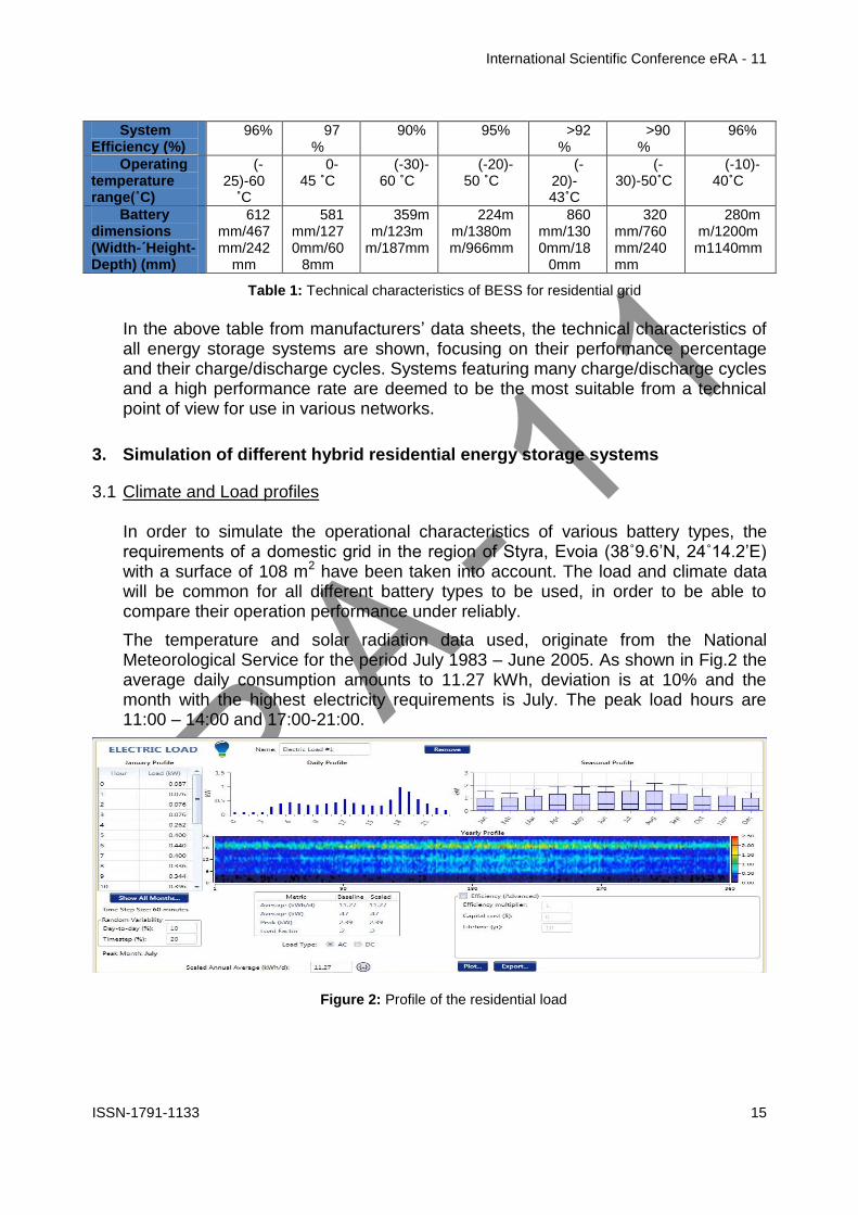
International Scientific Conference eRA - 11
ISSN-1791-1133 20
Battery type IV
9554 5000 6900
Battery type V
9073 5400 6816
Battery type VI
9072 2500 6958
Battery type VII
9058 10800 7125
Table 5 Results of the technical analysis
Based on the results of the simulation an engineer could state with certainty that the system which best meets the requirements of the domestic grid for which the study and simulation were carried out is the one by Battery type VII since over a period of 25 years it is the one with the longest life duration whilst is mean monthly state of charge remains at higher levels compared to the other energy storage systems
On the other hand if the requirement of our grid was for a battery energy storage system with high performance the battery type II would be the most effective choice so this systemrsquos performance should be 9772
Finally after the comparison of the technical characteristics for different battery types through HOMER Pro software the most critical technical characteristics of a BESS are
- Cycles to failure In a lifetime project of more than 15-20 years the most efficient system is the one that provides more cycles of chargedischarge
- State of charge By discharging an energy storage system between 50-70 can be achieved an increase in systemrsquos lifetime
- Efficiency The ability of a battery energy storage system to deliver grid as the largest possible quantity of the stored electric energy is the most critical criterion for the most efficient system
- Other quantities Quantities such as the nominal voltage nominal storage capacity batteryrsquos capacity depend on cell technology and the cell stacks that are assembled to create a battery storage system
References
[1] Gonzaacutelez FD Sumper A Bellmunt OG Robles RV A review of energy storage technologies for wind power applications Renewable and Sustainable Energy Reviews 2012162154-71
[2] Kaldellis JK Zafirakis D Kavadias K Techno-economic comparison of energy storage systems for island autonomous electrical networks Renewable and Sustainable Energy Reviews 200913378-92
[3] Sauer DU Storage Systems for Reliable Future Power Supply Networks In Urban Energy Transition Droege P editor Elsevier 2008
[4] Zafirakis D Overview of energy storage technologies for renewable energy systems In Stand-alone and hybrid wind energy systems technology energy storage and applications Kaldellis JK editor Woodhead Publishing 2010
International Scientific Conference eRA - 11
ISSN-1791-1133 21
[5] Zhang Q Multifunctional separatorinterlayer system fir high stable lithium sulfur batteries Progress amp prospects 2015 Elsevier BV
[6] X-B Cheng C Yan J-Q Huang P Li L Zhu L Zhao Y Zhang W Zhu S-T Yang Q Zhang The gap between long lifespan Li-S coin and pouch cells The importance of lithium metal anode protection 2016 Elsevier BV
[7] Marc Beaudin Hamidreza Zareipour Anthony Schellenberglabe William Rosehart Energy storage for mitigating the variability of renewable electricity sources An updated review 2010 Elsevier BV
[8] Table 3 Cycles to Failure httpwwwtoshibacomticpower-electronicsscib-rechargeable-battery
[9] Table 3 Cycles to failure httpsfenecondepagestromspeicher
[10] Table 3 Cycles to failure httpwwwhoppeckecomenproducttrak-power-lion
[11] Table 3 Cycles to failure httpwwwsiemenscominnovationenhomepictures-of-the-futureenergy-and-efficiencysmart-grids-and-energy-storage-bottled-sunlighthtml
[12] Table 3 Cycles to failure httpwwwsamsungsdicomessindexhtml
[13] Table 3 Cycles to failure httpwwwpanasoniccomauconsumerenergy-solutionsresidential-storage-battery-systemlj-sk84ahtml
[14] Table 3 Cycles to failure httpswwwteslacompowerwall
International Scientific Conference eRA - 11
ISSN-1791-1133 22
Fancy yarns for fashionable fabrics recent developments
Cristina Piroi
Faculty of Textiles - Leather and Industrial Management
Technical University Gheorghe Asachi Iasi Romania Tel +40 232 701143 E-mail cpiroitextuiasiro
Abstract
This paper presents the solutions currently offered by the textile machinery producers
for producing single spun fancy yarns as response to the customersrsquo demands for
spinning machines more flexible highly productive and easy to operate able to
manufacture a large variety of regular or fancy yarns specially designed for particular
applications and affordable
1 Introduction
Manufacture of yarns with a high degree of regularity is one of the most important aims for spinners However for some application a certain degree of irregularity is required to produce fabrics with a particular appearance such as uneven and rough surface that gives the feeling of moving or variations of colour intensity that make the fabrics more interesting for customers The yarns characterised by this kind of desirable lsquodefectsrsquo are known as effect yarns or fancy yarns they contain deliberately introduced irregularities arising from changes in yarn twist andor yarn count (thick or thin places) [1]These yarns are produced by using devices special developed for this purpose that creates discontinuities in yarn structure andor in their colour
During the last several years on the clothing market as well as in the furnishing and home textiles sectors the demands for refined fabrics with more distinguishing features increased continuously Consequently the demand for fancy yarns used for manufacturing new and modern fabrics has grown accordingly Whether used for outerwear home textiles upholstery fabrics or industrial textiles fancy yarns account for an increasing share from the total quantity of yarns produced worldwide
Presently fancy yarns are an essential feature of the modern fashion The denim production is a typical application for fancy yarns In the manufacturing of these fabrics yarns featuring a large numbers of effects are necessary so the ldquofancy denimrdquo effects to be clearly visible in the finished fabric These fancy yarns for denim are characterised by effects with natural appearance which are very similar to natural yarn defects [2]
The development of new types of fancy yarn for fashionable fabrics allows spinners or integrated textile groups to strengthen their relationships with the customers by offering them not only common yarn but also high-quality value-added products [3]
International Scientific Conference eRA - 11
ISSN-1791-1133 23
2 Types of fancy yarns
As a general definition fancy yarns are those yarns in which some deliberate decorative discontinuity or interruption are introduced of either colour or form or of both colour and form These discontinuities are incorporated with the intention of producing an enhanced aesthetic effect In recent years there has been an important increase of the interest in applications of single spun fancy yarns and fancy doubled yarns and these yarns have now a considerable commercial significance Most fancy yarns are produced by specialist fancy spinners using machines modified or developed for the purpose Others are produced from lsquofancy sliversrsquo which are used as minor components in yarns made by spinners using normal equipment [4]
Apart from the fancy doubled yarns which have most often a complex structure consisting of lsquocorersquo threads an lsquoeffect materialrsquo and in the more complex cases a lsquobinderrsquo which holds together the entire structure other types of fancy yarns may be obtained directly on the spinning machines by varying the spinning process conditions
The modern ring-spinning and rotor spinning machines can be equipped with certain devices able to produce single spun fancy yarns The desired effects in yarn are obtained by use of a microprocessor-controlled servomotor system which controls the spinning process This allows change of the rollers speed and consequently of the draft andor the twist enabling thus the creation of yarns with various effects Based on the types of effects introduced the single spun fancy yarns can be grouped into four categories slub yarn multi-count yarn multi-twist yarn and multi-effect yarn
Slub yarn
Slub yarn is the best-known and probably the most frequently used type of fancy yarn A slub yarn is one in which slubs are intentionally created to produce a desired effect Basically the slubs are thick places in the yarn They can be built in form of a gradual change in thickness with only a slight thickening of the yarn followed by its thinning to achieve the base yarn count Alternatively the slub may be three or four times the thickness of the base yarn and that thickness may be achieved for a very short length of yarn [4] Usually the slub yarns are characterised by rather short effects with the length varying between 3 and10 cm
On the ring spinning machine the yarns with slub effect are produced by varying the speed of the middle and back bottom rollers while the speed of the front roller as well as the spindles speed are kept constant This means that the twist per meter in the yarn remains the same (T1=T2) and the yarn are characterised by count
variations with varying twist factor ) (Fig1) [1]
On the rotor spinning machine the slub yarns are produced usually by incorporated electronically-controlled devices that briefly accelerate the feed roller The working principle of these devices is based on the variation of sliver amount supplied into the rotor while the rate of yarn delivered to the bobbin is kept constant However as a result of the doubling action inside the rotor it is not possible to produce slubs shorter than the circumference length of the rotor Any variation in the amount of
International Scientific Conference eRA - 11
ISSN-1791-1133 24
fibres supplied in rotor is spread over a minimum length which is equal to the rotor circumference As example for a rotor diameter of 36 mm the slub effects on rotor spinning machines are at least 113 cm long [1]
Multi-Count yarn
A multi-count yarn is a fancy yarn consisting of lengths of different yarn counts The multicount effect is achieved by controlled changes of yarn thickness on a certain
length while the twist factor is maintained constant ) To obtaining the mass variation along the yarn and create the fancy effects the main draft is periodically reduced through the temporary increases in speed of the back bottom roller and middle bottom roller The twist is adapted to each portion of yarn with different count so the yarn shows a succession of segments with various thickness but with the same twist factor (Fig2)
Figure 1 Slub yarn Figure 2 Multi-count yarn
A multi-count yarn is similar in many respects to slub yarn but due to the modified twist has a higher tenacity in the thin zones In contrast to slub yarn the effects have a longer wavelength giving a special look to the fabrics
Multi-Twist yarn
The fancy yarns with multi-twist effect are produced by applying different twist
factors ) and consequently different twist per meter (T1 T2) to the yarns with constant count (Fig3) These differences in twist creates variations in the yarnrsquos dye intake allowing to obtain fabrics with a special appearance Usually multi-twist yarns are produced with rather long effects of 10-50 cm
The multi-twist fancy yarn is obtained by means of the controlled and accurate acceleration of the front roller The twist variations in the yarn are incorporated by varying the delivery speed of the spinning machine whereas the total draft remains constant
Multi-effect yarn
Multi-effect yarn is a fancy yarn featuring a combination of slub effects multi-count effects and multi-twist effect (Fig4) The variations can be freely programmed in the
case of multi-effect yarn A change in mass can be combined with a twist factor which is not predefined This means that the twist and change in mass in the yarn can be freely selected
Figure 3 Multi-twist yarn Figure 4 Multi-effect yarn
International Scientific Conference eRA - 11
ISSN-1791-1133 25
Lately the fancy yarns obtained on ring-spinning machines and rotor spinning machines have become very popular they and are used most frequently in the denim production for upholstery fabrics and drapes as well as in production of single jersey and fine outerwear fabrics (Fig5)
Figure 5 Various types of fancy yarn fabrics (wwwrhytmfabricscom wwwetsycom)
3 Slub systems for fancy yarns
The Swiss company Amsler Tex provides solutions for production of fancy yarns on all kinds of spinning machines The company cooperates with all important manufacturers of spinning machinery (Marzoli Rieter SchlafhorstZinser Totota
International Scientific Conference eRA - 11
ISSN-1791-1133 26
etc) to develop complete systems for production of fancy yarns as alternative to ordinary yarn on the same machine [5]
Amsler systems are compatible with nearly any type of existing or new ring and open-end spinning frames The devices are installed either with a differential gear or with a direct drive system With the differential gear the creation of the slub is made with an individual slub drive The production of the base yarn is still driven by the basic drive of the spinning machine The high dynamic movement for the slub creation is superimposed through the differential gear This construction enables slub creation without thin places and prevents yarn breakage after a power failure
For the ring spinning frames Amsler provides three types of slub systems the basic slub system the multicountmultitwist system (MCMT) and extreme short slub system (XSS) (Table 1) Figure 6 shows the diagram of Amsler slub device on the ring spinning machine including multi-countmulti-twist function [5]
Amsler ring spinning systems
Minimal slub length
(milimeters)
Maximal number of slubs
(slubsmeter)
Minimul distance between yarn count
change
(meters)
Basic slub 30 10 -
MCMT (incl slub)
30 10 15
XSS 15 - 20 12 - 15 05
Table 1
Figure 6 Diagram of Amsler slub device on ring spinning machine [6]
For open-end frames Amsler Tex offers also three slub systems the standard system the high performance system and the high performance cooling system (Table 2) These systems may be upgraded with the optional multi-count multi-twist function [5]
International Scientific Conference eRA - 11
ISSN-1791-1133 27
Table 2
Figure 7 Working principle of Amsler open-end slub system [5]
Amsler open-end systems Maximum
number of slubs minute
Standard S
TD 150
High performance H
P 200
High performance cooling
HPC
300
All yarn effects produced with Amsler devices are digitally programmed using a dedicated design software Amsler E-Profi is a comprehensive software system for professional slub yarn development and production It has a modular structure and can also include a digital yarn scanner for quality control and slub yarn design [5]
The most comprehensive E-Profi package allows
Advanced creation of slub yarn programs (multicountmultitwist statistics XY yarn preview)
Slub view (analyzing digitized yarn)
Generation of slub yarn programs out of digitized yarn
3D fabric preview (based on weaving and knitting parameters)
Scanner software(laser or flatbed-scanner
During the spinning process the computer controlled drafting system uses the created slub yarn programs to modify the draft in order to obtain the designed fancy yarns
Figure 8 Creating effect yarn [5]
International Scientific Conference eRA - 11
ISSN-1791-1133 28
Figure 9 Designing fashion using E-Profi with fabric preview module [5]
4 Available solutions for producing fancy yarn
Marzoli Fancy Yarn Device
The first manufacturer who introduced a fully integrated device for fancy yarns on its spinning machines was Marzoli in 1999 There are four types of slub effects that can be obtained through continuous variation of the speed of the drafting rollers slub multi-count multi-twist and reverse slub The various combinations among these four slubbing effects can create a large diversity of yarn and fabric designs (Figure 10)
The slub effect is obtained through continuous variations of the main draft by increasing the speed of the back and middle rollers This causes reduction of the main draft and determine the increase of yarn thickness Otherwise to obtain the reverse slub effect the draft variation is negative leading to reductions of the yarn thickness
To design a slub Marzoli system requires setting its length in millimeters its thickness as a percentage of the base yarn (multiplier) and its pause (distance between one slub and the next) in millimeters [6]
Figure 10 Various types of slub yarns [6]
Usually the slubs length is set between 30 to 100 mm but in some cases slubs could be even shorter in order to produce an effect called malfile ie small and frequent slubs that create an effect similar to the natural irregularity of the yarn
The manufacturer claims that Marzoli Fancy Yarn Device is able of producing slubs shorter than 20 mm with up to 20 slubs per meter without compromising the yarn quality and strength by using last generation electronics high efficiency motors
International Scientific Conference eRA - 11
ISSN-1791-1133 29
mechanical transmissions light and solid as well as special acceleration ramps that lasts less than 01 seconds [10]
The multi-count effect is obtained through prolonged variations of the main draft The result is a yarn with different counts along its length Usually this effect is used together with the multi-twist effect in order to obtain interesting effects on fabric
The multi-twist effect entails twist variations that change the yarn diameter its compactness and consequently the behaviour in dyeing This creates interesting lighter and darker areas into the yarn and in the final product
The multi-count and multi-twist effects can be used together to create other interesting effects in fabric In this case the yarn does not have a constant count nor a constat twist For each count is applied a different twist based on selected
constant bdquo rdquo This effect combination is obtained through a variation of the main draft to modify the count and a variation of the front roller speed to modify the twist
Marzoli Fancy Yarn Device is capable of producing fancy yarns of variate forms and designs without requiring any modification to the spinning frame The variation in twist and draft are accomplished by modifying the speed of the independent motors that are already installed on the spinning frame
Rieter VARIOspin Fancy Yarn system
VARIOspin fancy yarn device is the result of cooperation between Rieter AG the supplier of systems for short-staple spinning and AmserTex provider of systems for producing fancy yarns The system is based on the drafting system drive FLEXIdraft which allows separate actuation of the drafting system drives and can be programmed by the user
The feed bottom roller (A) and the center bottom roller (B) are driven by an inverter-controlled motor while the delivery bottom roller (C) is driven separately by another inverter-controlled motor (Fig11) The bottom rollers of the drafting system are independently driven so it can change their rotation speed in accordance with a preset program required to produce a particular yarn effect [7]
Figure 11 FLEXIdraft drafting system drive for fancy yarn production [7]
The slub yarns are obtained by changes in mass effected via the control of the feed bottom roller and the middle bottom roller For an increase in mass they are accelerated thus reducing the total draft For a reduction in mass they are slowed down so total draft is increased To obtain the change in mass without the twist modification the yarn delivery speed and the spindles speed remain constant
International Scientific Conference eRA - 11
ISSN-1791-1133 30
When multi-count yarns and multi-effect yarns are spun changes in mass together with modification of twists per meter are performed all drafting bottom rollers changes their peripheral speed simultaneously in coordination with each other The yarn delivery speed is also changed
Rieters rotor spinning machines can also be equiped with the VARIOspin devices for fancy yarn Any desired effects can be created slub yarns multi-count yarns multi-twist yarns and combined multi-effect yarns The yarn count of the base yarn in fancy yarn spinning is Ne 3 to Ne 40 (Nm 5 to Nm 68) The change in mass of the effect is set in practice at -20 to +400 while twist modification varies between 50 and 150 [2]
More pronounced effects can be achieved by reducing production speed to some extent since a large increase in mass requires more time In principle the draw-off speed for slub sections is the same as for the base yarn However the number of possible effects per unit of time depends on the performance of the feed drive In some cases the delivery speed is reduced for short effects also featuring short spacing [2]
Behind every fancy yarn system there is a program with which the effects can be defined ie programmed The program for Rieter ring-spinning machines is VARIOspinData It enables effect patterns and their repeats to be programmed visualized optimized and managed on the computer (fig11) The formation of a moireacute structure in the fabric caused by a regular effect pattern can be prevented by modifying the program if such a structure is unwantedThe effect patterns created can be transferred to any Rieter ring-spinning machine with a VARIOspin device via a USB stick or optionally via the SPIDERweb data collection system [7]
Figure 11 Programming effects with VARIOspinData [7]
1 - Input of fancy yarn parameters 2 - Visualization of the fancy yarn 3 - Visualization of the yarn surface
International Scientific Conference eRA - 11
ISSN-1791-1133 31
TOYOTA Fancy Yarn Spinning Device
The ring-spinning machines RX300E from Toyota Industries can include optionally the Fancy Yarn Spinning Device that allows manufacture of many types of fancy yarns such as slub yarns multi-count yarns and multi-twist yarns
The operating principle of this device is based on e-Draft System the independently drive system for all three bottom rollers of the drafting systemThese rollers are driven by specialized servo motors which allow setting and changing the speed of each draft roller freely This makes possible slowing down the front roller andor speeding up the back roller in order to produce varied effects in yarn
Types of yarn that can be manufactured on Totota ring-spinning machines RX300E [8]
Positive slub yarn (increase up to 500 comparing the cross-section of base yarn) can be obtained with one of the following options
Front roller deceleration control (with change to twist) Back roller acceleration control (with no change to twist) Combined control of the front and back roller (degree of twist change
can be adjusted)
Negative slub yarn (decrease up to 30 comparing the cross-section of base yarn)
Back roller acceleration control
Multi-count yarn Fixed number of twisted threads (2-6) Fixed number of twists (1-70 twistinch) Any number of twists (1-70 twistinch)
Multi-twist yarn Number of twisted threads 15 - 10
Multi-count+Multi-slub
Slub on slub
Natural slub like
The special developed software Data Creator for Fancy Yarns makes it easy to record and manage the pattern simulations and settings data
Saurer Fancypilot
To meet the demands of a market for fancy yarns with continuous growth the Saurers strategy was initially focused on developing integrated user-friendly solutions for ring and rotor spinning machines Additional mechanical devices were retrofitted to the machine to produce fancy yarns but this approach led to reductions in productivity and also in increases of system complexity
Currently the ring spinning machines Zinser with electronic drafting control system ServoDraft are available for producing fancy yarns both from short-staple and long-staple fibres The draft and the twist can be varied in a controlled manner so slubs of different thickness and lenghts can be introduced in yarn The twist can also be varied for the production of multi-twist yarns and in contrast to previous retrofit solutions now can be spun even yarns with long-wave draft variations [9]
International Scientific Conference eRA - 11
ISSN-1791-1133 32
For rotor spinning machines was developed Fancynation a complete modular system hardware and software fully integrated available both for automatic rotor spinning machines Autocoro and semiautomatic BD machines On the Autocoro 9 this cost-effective option allows to produce up to 5 different fancy yarns simultaneously or fancy yarns and standard yarns in parallel on the same machine [11]
FancyPilot is the software used on the Zinser ring spinning machines and Schlafhorst rotor spinning machines to design fancy yarns The effects are designed managed and controlled on a PC with all design parameters lot and customer data being stored in a database that can be used also in production of standard yarns
5 Conclusion
Although fancy yarns account for only a small proportion of total yarn volume they are in considerable demand depending on fashion trends During the last years the demands for refined fabrics with more distinguishing features increased continuously These fabrics often created by fashion designers provide a higher profit margin when compared with traditional fabrics so more and more spinners are interested to include fancy yarns in their product range
The modern ring-spinning and rotor spinning machines can be equipped with slub devices able to produce single spun fancy yarns The desired effects in yarn are obtained by use of a microprocessor-controlled servomotor system which controls the spinning process There are four basic types of slub effects that can be obtained slub multi-count multi-twist and reverse slub The various combinations among these four slubbing effects can create a large diversity of yarn and fabric designs
The possibility of producing fancy yarns and regular yarns on the same spinning machines by employing new and more advanced integrated slub devices allows to the spinning mills diversifying the range of products without additional running costs as well as strengthen their relationships with the customers
References
[1] R Maier Through thick and thin ndash with Rieterrsquos VARIOspin Link-The customer magazine of Rieter Spun Yarn Systems Vol 22 No 562010 p8-9
[2] M Werner Rotor-spun yarns with fashionable effects for ldquofancy denimrdquo Link-The customer magazine of Rieter Spun Yarn Systems Vol 22 No 562010 p12-13
[3] Amsler-Tex Slub yarn devices for spinning machines httpwwwptjcompk200802-08PDF-February200849-20Spinning20-20Amslerpdf
[4] RH Gong RM Wright Fancy yarns Their manufacture and application Woodhead Publishing Ltd Cambridge England
[5] Technology for textile fashion Brochures of Amsler Tex company [6] Fancy Yarn-Technology for superior flexibility Brochures of Marzoli SpA company [7] R Maier VARIOspin ndash for individual effects in ring-spun and compact yarns Link-The customer
magazine of Rieter Spun Yarn Systems Vol 22 No 562010 p10-11 [8] Ring spinning frame RX300 Brochures of Toyota Company [9] Saurer Fancynation - httpsissuucomoerlikontextilegmbhdocsfancynation [10] httpwwwmarzolicomen [11] httpschlafhorstsaurercomenautocoro-9
International Scientific Conference eRA - 11
ISSN-1791-1133 33
Nonconventional technology for production of decorative cushions
IFilip1 CSava 2 MCiocoiu2 GPriniotakis3
1 SC TAPARO Tg Lapus Romania E-mail ioanfiliptaparoro
2 Textile - Leather amp Industrial Management Faculty ldquoGheorghe Asachirdquo Technical University Iasi Romania
E-mail csavatextuiasiro mciocoiu41yahoocom
3 Textile Department Piraeus University of Applied Sciences Greece gprinteipirgr
Abstract On the market there is a high demand for decorative cushions essential components of the sofas The market are offering lines for the production but at big price and consequently the TAPARO Company Romania propose achieving a production line of decorative cushions with the original conception but with reasonable price For this was used the recovered equipments from cotton spinning mills but and equipment own conception The decorative cushion is from the same material like the sofa and the cushion basket is made of nonwoven textile and filled with a mixture of polyester fiber and polyurethane sticks Maintaining of the cushion geometry for a long time depends on the size and weight of cushion and of the basket of cushion with multiple cells In the paper are presents the changes did on the spinning machines to be used with new function and also achived the machinery of own conception Also in the paper are showed the quality characteristics of the decorative cuchions Keywords fiber polyester polyurethanesticks mixture cushion
1 Introduction
Particularly because of high demand for decorative cushions essential components of the TAPARO Company Romania product the sofas led to the idea of achieving a production line of decorative pillows from original conception considering the high price of identical lines on the market[12] Necessity the production line of decorative cushions was imposed from increased the production of sofas and for another hand of the realization possibility of the line at reasonable price using some of the recovered equipment from cotton spinning technological lines but and equipment own conception Unlike conventional cushion the decorative cushion is from the same material like the cover of sofa and the cushion basket is made of nonwoven textiles and the filling is a mixture of polyester fiber and polyurethane waste Maintaining of the cushion geometry for a long time depends on the size and weight of cushion and of the basket of cushion with multiple cells The mixture of polyester fibers and polyurethane cut waste is an alternative to replace conventional materials in cushions namely -polyester fibre can be fibre at first usage or fibre recovered from nonwoven textiles after cutting panels used in making sofas chairs etc
International Scientific Conference eRA - 11
ISSN-1791-1133 34
-superior utilisation of polyethylene waste with density between 21 to 25 Kgm3 resulting in the process of obtaining components of the sofa - the presence of the polyurethane cut into sticks and individualization polyester fibres in a homogeneous mixture assure good volume and the form of decorative cushions By using polyurethane waste as a component of the mixture forming cushions is assured a significant contribution to maintaining a clean environment Basically best it behaves in a cushion the mixture from silicone polyester fibre 30-32 mm cutting length and density 6-7 dtex and the polyurethane sticks [3]
2 Nonconventional technological line for decorative cushions
Some of the machines from unconventional line were bought from spinning mills mills which were either upgraded or were closed for various reasons These machines have been modified according to the new mode of use and the other part of the equipment from line have been designed and manufactured in the Company TAPARO (figure 1)
Figure1 Schematic unconventional production line of decorative cushions
1 Silicone polyester fibre bales 2 Sack with polyurethane sticks 3 Hopper feeding Trutzschler with weighing 4Opener 5 Condensor Trutzschler 6 Collector conveyor with striking point 7 Transport
ventilator Trutzschler 8 Cleaner with two axial drums Trutzschler 9 Opener Rieter 10Presortat with pressure gauge 11Compressed air pipe 12 Opener Rieter ERM model B5 13 Table for filling cushions 14 Order pedal for filled the cushion 15 Cushions conveyor 16 Electronic balance
17 Sewing machine
3 Made changes on machineries from spinning
Because the line is a succession of machines some of which were used in spinning cotton in what follows will present these changes to equipment and machinery own conception
31Hopper feeding Trutzschler for polyester siliconate fibres
Feeding of fibrous material in the technological process of obtaining decorative cushions is carried with the hopper feeder Trutzschler type KNW [4] (noted 3 in fig 1) who underwent modifications shown in Figures 2 and 3 in comparation with the
International Scientific Conference eRA - 11
ISSN-1791-1133 35
original version The cylinder equalizer is replaced with the lattice equalizer 9 equipped with slats with conic section The space between the lattice equalizer and inclined lattice 10 is at least 4mm thus creating a potent effect of teasing by wresting
Figure 2 Hoppe feeder Trutzschler type KNW with weighing for polyester fiber
1-cylinder with discs 2-photodetector 3- bunker dispenser 4- the superior mobile flap 5 ndash the mobile flap
bunker 6-conveyor 7- main engine (particularly resistant construction to frequent starts) 8- engine driving of
the main engine 9- feeder lattice equalizer 10- spiked lattice
32 Original opener design
Because the the raveling of the fiber tuft in the hopper feeding is insufficient was placed after this a designed an original opener (noted 4 in fig 1) with the cylinder equipped with saw-tooth clothing Thus the raveling of silicon fiber tuft is realized in restraint state The preset quantity of fiber depending on the recipe of mixing falls from basket 1 on the feeder table 2 inclined at 45o Thus it form a fibrous layer pressed by the wood cylinder 3 The gauge between feeder cylinder 4 and feed lattice 2 adjust the material quantity from the dispenser and the thick fibrous layer formed on the feeder lattice The Cylinder 6 has 248 mm diameter is with saw-steel clothing Graff C-55-6
Figure 3 The original opener for the polyester fiber 1 - basket 2 - feeder table 3 - cylinder pressure 4 -cylinder feeder 5- cover feeder cylinder 6- devil
cylinder 7- cover devil cylinder 8 -discharge pipe of individualized fibers 9- grill 10 semi-stiff linear
To achieve an more advanced loosening was fixed to the side walls one semi-stiff lineal 10
International Scientific Conference eRA - 11
ISSN-1791-1133 36
33 Hopper feeder Trutzschler for polyurethane sticks
The supply of polyurethane sticks with the participation quota imposed by recipe is via a same hopper feeder Trutzschler KNW [4] (noted 3 in fig 1) at which were made two key changes - the equalizer role of inclined lattice is canceled - nail bars are replaced with metal scraper
Figure 5 Hopper feeders with inclined lattice with with metal scraper a-side view of hopper feeder1- inclined lattice 2 - plate scraper profile
As shown in fig 5 collecting conveyor table 1 via these scrapers 2 takes the relatively constant quantity of sticks polyurethane and will unloaded its in the feeder Trutzschler KNW
34 Conveyor collector with striking point (noted 6 in fig 1)
Figure 6 Conveyor collector with striking point (noted 6 in fig 1) 1-transport table 2-inclined conveyor 3- opener 4-permanent magnet 5-pipe I- LVS capacitor
I hoper feeder for polyester fibersII-hoper feeders for polyurethane sticks
The conveyor 1 with polyester fibres individualized discharged from the feeder I and with the polyurethane sticks downloaded from the feeder II brings its in the work area of the opener cylinder 3 and conveyor 2 adjusted accordingly with it and take the material ldquosandwichrdquo composed of polyester fibres and polyurethane sticks and pneumatically are conveyed under the permanent magnet 4 and conduit ventilator Trutzschler 425 TV 5
International Scientific Conference eRA - 11
ISSN-1791-1133 37
35 The homogenization of mixture from tow components
The quality of decorative cushions depend of the homogeneity of the mixture of the components fibres polyester and polyurethane sticks to prevent defects (improper filling of the cushions etc) The correct adjustment of feeders ensures the supply adequate quantities of the components but is insufficient for intimate blending To obtain a good mixture were used two machines with the cleaning role in cotton mill which in this technological line provide an intimate mixing of these two components or obtaining a intimate mixture of these two-component in line are used two machines with cleaning and teasing role in cotton mill but which in this case provide intimate mixing of the two components and they are shuffler axial Truschler AXI- FLO and opener Rieter ERM (denoted on fig 1)
351Shuffler axial Trutzschler AXI-FLO
To achieve an intimate mixture between siliconate polyester fibres and polyurethane sticks in the shuffler axial Trutzschler AXI-FLO [4] (noted 8 in fig1) was make the following adjustments -the fan provides the transportation of the mix from two-component with air speed from 12 -15 m s but is advisable using the lower limit of speed to maintain in instalation the mixture more time for enhancing the mixing effect - Bars of grids 5 and 6 were completely closed - Speed drum 3 is 422 rot min left sense of rotation - Rotations drum 4 is 400rot min left sense of rotation - Flap 9 open to positions 78 on the nameplate ensuring for the fibrous material a spiral route about 6-8 tours
Figure 7 Shuffler axial Trutzschler AXI-FLOW 1 supply line 2 screen (damper) 3 4 mixing drums 5 6 grills 7 piece adjustable 8 exhaust pipe
(tubing) 9 flap 10 baffle plate 11 the handle for adjusting the grill 12 waste box 13 observation windows 14 access doors
352Opener Rieter ERM
At the exit of this machine the fibrous mixture two-components is sent to storage to upper chambers 2 (Fig 7) because the simultaneous operation of the four Trutzschler FBK 12 feeders used for filling the cushions ( noted 9 in fig 1) impose keeping constant the amount of material and requires the introduction of some bunker with appropriate storage capacity and with possibility to start and stop the flow depending on mixture consumption (fig 7) For this scope is used the opener
International Scientific Conference eRA - 11
ISSN-1791-1133 38
Rieter B5 5 [5] with a vertical hopper 2 at whose outer wall lamellar 3 allows removing the dust and air At the bottom of the hopper there is a smooth cylinder 6 and a perforated drum 11 that allow the formation of a layer of the mixture over the pair of feeders cylinders 7
Figure 8 Opener Rieter ERM
1- fibers supply line 2- vertical hopper- 3 posterior lamellar wall 4 -pipe exhaust air and dust 5- waste outlet pipe 6- cylinder smooth 7- feed cylinder 8- grill 9- air outlet 10- cylinder with
rigid garnish 11- drum sieve12- pipe for fibrous material evacuation
36 Installation for dosing of the fibrous unconventional mixing
For transportation the unconventional mixture from opener Rieter to each the cushion basket is used a pneumatic installation and 4 feeders Truzschler FBK (noted 12 in fig1) Pneumatic installation ensure uniform filling of the upper bunker of each feeder Truzschler FBK and by through the lower bunker of it assures pneumatic dosing and filling the mixture in the cushion basket
Figure 9 Pneumatic supply system for mixture of polyester fiber -polyurethane sticks 1-Opener Rieter2 Transport ventilator TV 425 3- pipe end 4- pressure control device
5-distribution pipe 6- Trutzschler FBK feeders
To the TrutzschlerFBK feeder have made the following changes 1 The acting of borrowers cylinder 11 it do through a low power motor (035Kw) and a transmission chain 2 During filling hopper lower cylinder debtors11 is stationary their operation is controlled only by the operator The adjustment of amount of mixture is from 100g to 600g
International Scientific Conference eRA - 11
ISSN-1791-1133 39
3 The lower bunker accumulates a quantity of material discharged in 3 to 5 seconds 4 Cylinder feeder 6 receives a stop command to the achievement air pressure in the lower hopper 5 Was replace chute for directing the fibrous layer to the feeder cylinder with a funnel for introducing mixture into the basket cushion 6 Was replace the existing switch (250-350 Pa) with a pressure switch with electronic control for adjusting the air pressure increase beach in the bunker or the quantity of material stored (25 -75 mm Hg water respectively 250-750 Pa) 7 Feeder 6 cylinder receives a stop command to the achievement of predetermined air
37 Installation for filled of the cushion basket
The worker acts the pedal 14 (noted 14 in figure 1) and command the fan and the cylinder 11 (figure 9) and the material is discharged in the cushion basket and the foot must up from the pedal when the pillow is filled then and the cycle repeats Depending on the of number baskets of cushion and it final weight is adjusted f material by some pedal actions that the material from the lower bunker is transferred in cushion basket
4 Results and discussions
41 Checking the accuracy operating of the hoper feeders
To verify the accuracy of operation of the those feeders was realized determinations for the 3 variants of the mixture The taken tests after Rieter opener from 100g 200g and 300g for each variant mixing and realized weightings for each of the two components With the results was calculate the averages and the variation coefficients of thereof In the figure 10 is the histogram of the coefficients of variation for two feeders used for polyester fibre and for polyurethane sticks Is noted that in the case of mixture polyester fibre 100g polyurethane sticks 900g the results are out of recommendations but the average values of the dispensers are very close to those set for each respective dispenser
Figure 10 Histogram of the coefficients of variation of weightings
for each from 2 those feeders
The coefficients of variation are higher for polyester fibre when the quantity of dispenser is below 300g and in case the sticks of polyurethane because sticks table cannot be changed they vary plus or minus from the value set on the scale
International Scientific Conference eRA - 11
ISSN-1791-1133 40
dispenser Also must it is respected provided that the waste polyurethane have close densities between 21-25 [kg m3] [2]
4 2 Checking the function precision of load lines cushions
To verify the accuracy of weighing of the lower hopper of feeders Trutzschler FBK for 3 blends and with different amounts of blended material were carried out randomly set number of determinations For analyze the separation of the two components from the mixture was performed manually and was used the balance Startorius 2354 with an error 001g
With the variation coefficients for the three variants mixing was done a comparative graphical representation as in figure 11
Figure 11 Histogram of the coefficients of variation of cushion mass on blends
For a feeder FBK used in a line for supplying the cards the variation coefficient of linear density of layer fibrous is 115 [3 4] In the case of line production of cushions with non-conventional mixture and the fact that the feeder does not form a continuous fibrous layer he adjusted by feeding amount of the material of the pressure switch the operation is intermittent the coefficient of variation the weighing has values in the range 113 -3 08 and the analysis of the histogram of figure 11 so well below the 5 admitted into the upholstery [1]
5 Conclusions
Originality of the line pneumatic filling of the cushion basket consists in 1 Unlike feeder conventional at the line presented silicone polyester fibre material is subjected to a process of advanced individualization and then using a capacitor is discharged on the conveyor belt 2 For the of polyester fibres was realized a original hoper equipped with cylinder with metallic clothing the operation of individualization is realized in catching condition 3 The feeder Trutzschler doses the quantity of material composed of polyester fibre and polyurethane sticks 4 The main function of shuffler axial Trutzschler Axi FLO is to the mixing of the two components in the airflow 5 The aggregate Rieter has role of feeding mechanism by changing the flow of fibrous material 6 Researchers presented show that unconventional line for product decorative cushions give good results
International Scientific Conference eRA - 11
ISSN-1791-1133 41
References
[1] Scott Forrester ldquoUpholstery Basics Earthrdquo Lodge Publishing Torrington Wyoming 82240 ISBN 978-0-6151-8813-3
[2] Ioan Filip ldquoContributii teoretice şi experimentalela diversificarea producţiei de articole tehnice destinate industriei de tapiţerierdquo Doctoral thesis Iasi 2014
[3] SavaC IchimM bdquoFilatura de bumbacrdquo Iasi Ed Performantica ISBN 973-30-088-2 [4] www Trutzschler com [5] www Rietercom
International Scientific Conference eRA - 11
ISSN-1791-1133 42
The effect of cottonised flax and hemp as eco-friendly substitutes for cotton on the comfort properties of knitted fabrics
M Ichim1 D Făricircmă2 C Sava3 GPriniotakis4
1 Dpt of Engineering and Design of Textile Products ldquoGheorghe Asachirdquo Technical University of Iaşi Iaşi Romania
TelFax +40 232 230491 E-mail michimtextuiasiro
2 Dpt of Engineering of Knitting and Ready-Made Clothing ldquoGheorghe Asachirdquo Technical University of Iaşi Iaşi Romania
TelFax +40 232 230491 E-mail dfarimatextuiasiro
3 Dpt of Engineering and Design of Textile Products ldquoGheorghe Asachirdquo Technical University of Iaşi Iaşi Romania
TelFax +40 232 230491 E-mail csavatextuiasiro
4 Textile Department Piraeus University of Applied Sciences Greece
gprinteipirgr
Abstract
The paper presents the results of a research concerning the effect of partial cotton replacement by cottonised flax and hemp on the comfort properties of knitted fabrics Rotor spun yarns of 59 tex and 100 tex linear density from 30 cottonised flax70 cotton 30 cottonised hemp70 cotton and 100 cotton blends obtained on the cotton spinning system have been used to produce 1 x 1 rib knitted fabrics on a manual flat knitting machine The comfort properties of the knitted fabrics such as porosity air resistance water vapour resistance and thermal resistance have been evaluated Keywords cottonised flax yarn cottonised hemp yarn knitted fabrics comfort properties
1 Introduction
As natural fibres cotton flax and hemp could be considered environmentally
friendly because they are fully biodegradable and renewable raw materials However these criteria alone are not an accurate indicator of their full environmental impact The pollution associated with fibre cultivation and processing must also be taken into consideration in assessing the environmental friendliness of textile products In this respect cotton fibres and products are not considered environmentally-friendly because conventional cotton farming demands substantial amounts of pesticides fungicides herbicides and chemical fertilizers which pollute soil and groundwater Additionally cotton growing requires large amounts of water with negative impact on environment and water resources [1 2] In contrast to cotton flax and hemp are more environmentally friendly Due to its dense foliage higher pest and disease resistance hemp can be grown without the use of
International Scientific Conference eRA - 11
ISSN-1791-1133 43
herbicides pesticides or fungicides and with very little nutrients Even if flax cultivation requires a certain amount of pesticides herbicides and nutrients their levels are much lower than those required for cotton crops Hemp and flax are drought-tolerant requiring only regular rainfall Besides hemp can extract and accumulate heavy metals such as copper lead zinc and cadmium from contaminated soils resulting in soil remediation [3 4]
In contrast to the cotton fibres that are single cells the technical flax and hemp fibres are in the form of bundles of individual cells (elementary fibres) Because the dimensions of the elementary fibres are similar to those of cotton fibres their extraction (called cottonisation) and processing in blends with cotton on the cotton spinning equipment has gained increasing interest [5] When compared to the traditional flax and hemp spinning systems the cotton spinning system is less labour intensive more efficient and more economical
The aim of this research work was to study the effect of partial replacement of the polluting cotton with more eco-friendly fibres as flax and hemp on the comfort properties of the knitted fabrics that come into direct contact with the skin The wear comfort requirements that consumers impose to the apparel producers can be accomplished by the thermo physiological function of clothing The thermo physiological comfort relates to the way clothing dissipates metabolic heat and moisture and depends on many factors such as fibre nature and size yarn type (spun monofilament multifilament textured yarn) fibre and yarn characteristics knitting patterns garment sewing patterns the applied finishing treatments [6]
In this study rotor spun yarns of 59 tex and 100 tex linear density from 30 cottonised flax70 cotton 30 cottonised hemp70 cotton and 100 cotton blends obtained on the cotton spinning system have been used to produce rib knitted fabrics on a manual flat knitting machine The applications of the knitted fabrics are single layer apparel products The comfort characteristics of these apparel products are given solely by the comfort characteristics of the knitted fabrics such as water vapour resistance Rv [mmm2middothg] air resistance Rpa [m2hmmkg] thermal resistance Rt [m2middothoCKcal] and porosity Pz [] Based on the application of the knitted fabrics the comfort requirements that have to be accomplished are as follows low water vapours resistance low air resistance and low thermal resistance
2 Materials and methods
Rotor-spun yarns of 59 tex and 100 tex linear density from cottonised flaxcotton and cottonised hempcotton blends have been obtained on the cotton spinning system using a double carding technology [5] All-cotton yarns of identical linear density were also spun for comparison purpose using standard spinning mill procedures and practices Yarn properties were measured under a standard atmosphere of 20 plusmn 2degC and 65plusmn 2 RH The linear density of yarns has been measured according to SR EN ISO 2060 standard TINIUS OLSEN H5 K-T tensile tester was used to assess the tensile properties of yarns according to EN ISO 2062 standard Twist measurements were performed on a Mesdan twist tester according
International Scientific Conference eRA - 11
ISSN-1791-1133 44
to EN ISO 2061 standard using a clamping distance of 250 mm Yarn mass irregularity was tested on an Uster Tester-II apparatus at a speed of 25 mmin
The properties of rotor yarns are presented in Table 1 As can be seen in Table 1 when compared to 100 cotton yarns of similar linear density the cottonised flaxcotton and cottonised hempcotton blended yarns have lower tenacity lower breaking elongation higher twist and higher irregularity of linear density strength twist and mass The differences between the characteristics of blended yarns containing cottonised flax and hemp and the characteristics of 100 cotton yarns can be explained by the fact that the cottonised flax and hemp fibres are coarser and more variable in fineness than cotton and thus the number of fibres in the cross-section of blended yarns is lower than in the cross-section of all-cotton yarns [7]
Table 1 Yarn properties
Characteristic 30 cottonised flax70 cotton
30 cottonised hemp70 cotton
100 cotton
100 tex 59 tex 100 tex 59 tex 100 tex 59 tex
Linear density tex 102 565 971 575 99 595
CV of linear density 18 34 26 35 14 32
Tenacity cNtex 10 10 903 85 102 104
CV of breaking strength 93 86 157 124 6 8
Breaking elongation 8 56 61 55 8 63
Twist rpm 460 598 470 642 354 459
CV of twist 3 26 2 32 16 23
CVm 161 171 201 186 121 128
The yarns have been converted into 1 x 1 rib knitted fabrics on a manual flat knitting machine characterized by one negative feed system two needle beds and E 10 gauge The obtained variants of knitted fabrics and their course wale and stitch densities are shown in Table 2
Table 2 Knitted fabric variants and course wale and stitch density
Knitted fabric
variant
Fibrous composition Yarn linear
density [tex]
Course density
[courses 5 cm]
Wale density [wales 5 cm]
Stitch density [loops25cm2]
V1 30 cottonised flax 70 cotton 100 tex 48 28 1344
V2 30 cottonised flax 70 cotton 59 tex 43 26 1118
V3 30 cottonised hemp70 cotton 100 tex 45 26 1170
V4 30 cottonised hemp70 cotton 59 tex 45 28 1260
M1 100 cotton 100 tex 55 28 1540
M2 100 cotton 59 tex 48 34 1632
Comfort properties of the knitted fabrics have been tested in laboratory static conditions (63 RH 187degC)
International Scientific Conference eRA - 11
ISSN-1791-1133 45
The knitted fabrics are considered capillary-porous bodies and their porosity can be reported as pore percentage defined as the ratio of pore volume to knitted fabric volume For practical measurement of knitted fabric porosity the picnometric method has been used based on fabric real density and apparent density
The thermal insulation capacity has been expressed as thermal resistance Rt [m2middothmiddotoCKcal] [6]
In order to assess the water vapour transfer through the knitted sample the water vapour resistance Rv [mmm2middothg] has been determined according to STAS 9005-79 standard
The air permeability has been expressed by air resistance Rpa [m2hmmkg] of knitted sample The measurements have been done using a pressure difference of 10 mm of water column according to STAS 5902-70
Twenty individual values for each knitted sample have been averaged in order to obtain de mean value of porosity air resistance water vapour resistance and thermal resistance
3 Results and discussions
The mean values of porosity air resistance water vapour resistance and thermal resistance of the knitted fabrics are presented in Table 3
Table 3 Thermo physiological characteristics and porosity of knitted fabrics
Fabric variant
Pz [ ]
Rv [mmm2middothg]
Rpa [m2hmmKg]
Rt [m2middothmiddotoCKcal
V1 7087 0111 00033 00328
V2 7885 0091 00015 00566
V3 7173 0117 00042 00379
V4 7376 0091 00029 00473
M1 7011 0131 00073 00143
M2 6924 0123 00060 00269
The knitted fabric porosity is a synthetic structural parameter that includes the structural parameters of fibres yarns and knitted fabrics and also the finishing treatments When compared to other textile materials the knitted fabrics have higher porosity Taking into consideration the knitted fabric porosity Pz [] as the main factor that influences the values of the experimentally determined comfort characteristics (water vapour resistance Rv [mmm2middothg] air resistance Rpa [m2hmmkg] thermal resistance Rt [m2middothoCKcal]) their analysis will be done in accordance with the values of porosity Thus as can be seen in Table 3 the knitted fabric variants with content of cottonised flax or cottonised hemp show higher porosities than cotton knitted fabrics This can be explained by the higher bending rigidity and higher twist of blended yarns when compared with cotton yarns and by the lower stitch density of the fabric variants with content of cottonised flax or hemp (Table 2) Even if by cottonisation flax and hemp fibres become softer they are still stiffer than cotton fibres Images of knitted fabrics that exemplify the differences in porosities are presented in Figure 1
International Scientific Conference eRA - 11
ISSN-1791-1133 46
a
b
c
Figure 1 Images of knitted fabrics obtained from 59 tex yarns (4x magnification)
a) 100 cotton b) 30 cottonised flax70 cotton c) 30 cottonised hemp70 cotton
Taking into account the application of the obtained knitted fabrics the comfort requirements that have to be accomplished are as follows low water vapour resistance low air resistance and low thermal resistance
A fabric is comfortable as long as the water vapour released by the skin (perspiration) pass at a fast rate through its pores The results in Table 3 show that the knitted fabrics with content of cottonised flax or hemp offer less resistance to moisture transfer when compared to cotton fabrics This could be due to the fabricsrsquo high moisture absorbency and high porosity
The resistance of a fabric to the flow of air is an important factor in the performance of summer clothes that come into direct contact with the skin The lower the resistance to the air flow the greater the intensity of cooling effect is The results in Table 3 show that cottonised flax and hemp blended fabrics have less resistance to air flow as compared to 100 cotton fabrics and therefore permit more air to pass through This behaviour can be attributed to the higher porosity of these fabrics
The thermal comfort of the body requires equality between the heat produced by the metabolism and the heat lost from the body The resistance of a fabric to the transfer of heat has considerable influence on the comfort of the wearer because determines the rate at which the metabolic heat can be lost The thermal resistance of cottonised flax and hemp blended fabrics measured under dry static conditions is higher than the thermal resistance of 100 cotton fabrics because of the air entrapped in the knitted fabric structure due to the higher porosity However many researchers have found that the environmental air velocity and the water vapour transfer through fabric may cause thermal resistance loss [8 9] Therefore it may be assumed that under dynamic conditions the heat loss through the cottonised flax and hemp blended knitted fabrics is higher than the heat loss through the cotton fabrics due to the lower resistance to air flow and moisture transfer
It may be observed from Table 3 that for all variants of blends an increase in the yarn fineness has as result an increase in the knitted fabric porosity that lead to a reduction of air resistance and water vapour resistance Also an increase in the yarn fineness causes the thermal resistance measured under static dry conditions to increase
International Scientific Conference eRA - 11
ISSN-1791-1133 47
4 Conclusions
Flax and hemp are renewable biodegradable fibres that provide an eco-friendly alternative to conventional cotton which is environmentally destructive Unlike cotton which grows best in warm and moist climate flax and hemp crops grow well in a wide range of climatic conditions and have a considerable potential to develop a bio-based economy
The aim of this research work was to study the effect of partial replacement of cotton with cottonised flax and hemp on the comfort properties of the knitted fabrics that come into direct contact with the skin
Based on the results of this research the following conclusions can be drawn
Adding cottonised flax and hemp to cotton knitted fabrics the water vapour resistance and the air resistance decrease which improve moisture wicking and drying speed This means that moisture is channelled away from the skin surface and the skin is kept cool
Due to the higher porosity of the cottonised flax and hemp blended knitted fabrics their thermal resistance measured under static dry conditions increases when compared to cotton fabrics
The fabrics obtained from finer yarns show lower water vapours resistance and air resistance and higher thermal resistance
References
[1] Chen H-L Burns L D ldquoEnvironmental Analysis of Textile Productsrdquo Clothing amp Textiles Research Journal 24 3 248 2006
[2] Van der Werf H MG Turunen L ldquoThe environmental impacts of the production of hemp and flax textile yarnrdquo Industrial Crops and Products 27 1 2008
[3] Piotrowski S Carus M ldquoEcological benefits of hemp and flax cultivation and productsrdquo Available from httpeihaorgattach64311-05-13_Ecological_benefits_of_hemp_and_flaxpdf Accessed 2016-06-25
[4] Franck R R Bast and other plant fibres Woodhead Publishing Limited Cambridge England 2005
[5] Sava C Ichim M ldquoYarns and Woven Fabrics Made from Cotton and Cottonised Flax Blends for Upholstery Applicationsrdquo Fibres amp Textiles in Eastern Europe 23 5(113) 30-34 2 2015
[6] Farima D ldquoConfortul si functiile produselor textile si din pielerdquo Ed Performantica Iaşi 2008
[7] Sava C Ichim M ldquoHemp ndash an environmentally friendly alternative to cottonrdquo The 15th Romanian Textiles and Leather ConferencendashCORTEP 2014 Poiana Braşov 4 - 6 September pp 57-60 2014
[8] Shekar RI Kotresh TM Subbulakshmi MS Vijaylakshmi SN Prasad ASK ldquoThermal resistance properties of paratrooper clothingrdquo Journal of Industrial Textiles 39(2) 123-148 2009
[9] Ghaddar N Ghali K Jones B ldquoIntegrated human-clothing system model for estimating the effect of walking on clothing insulationrdquo International Journal of Thermal Sciences 42 (6) 605-619 2003
International Scientific Conference eRA - 11
ISSN-1791-1133 48
The influence of the waterproof membrane on the thermal comfort
properties of multi-layer clothing system E Codau
Technical University ldquoGh Asachirdquo Iasi Textile Leather and Industrial Management Faculty Str Prof Dr Doc Dimitrie Mangeron No 28 700050-Iasi Romania
eonofreitextuiasiro
Abstract
In this paper two multi-layer fabric systems intended for firefighters were tested in order to determine the basic parameters of the thermal comfort The thermal comfort was evaluated effectively by measuring the thermal properties of clothing on the sweating guarded hotplate (skin model) The first assembly is composed from the external layer middle layer (thermal insulation) and internal layer (moisture barrier - hydrophilic polyurethane (PU) membrane coated on knitted fabric) The second one contains external layer middle layer (thermal insulation) and an internal layer (liner) Both analysed assemblies contain the same external layer and middle layer
These layers were tested as monolayer and in multi-layer clothing systems The influence of the membrane on the thermal and water-vapour resistance of the multi-layer fabric system was discussed
When the combinations of different materials are used for a multi-layer fabric system the thermal comfort is dependent not only on the properties of each monolayer but also on the manner in which they act together The results showed that the monolayer acting as a moisture barrier has a considerable influence on the overall water-vapour transport abilities The position of the moisture barrier in the assembly is also important in the overall value of water-vapour resistance of the multi-layer system
Keywords moisture barrier hydrophilic polyurethane membrane multi-layer textile system protective clothing resistance of water-vapour Sweating Guarded Hotplate (skin model)
1 Introduction
Various protective clothing (ex for firefighters) and many outdoor sports clothes (ex for cycling running skiing climbing etc) should show excellent barrier properties and at the same time good hygienic characteristics and high comfort of use For these applications waterproof and yet water-vapour permeable (breathable) textiles are state of the art [1] For this purpose membranes with a high effective protection against water air-non-permeable and with high permeability for water-vapour can be used in monolayer or multi-layer clothing system
International Scientific Conference eRA - 11
ISSN-1791-1133 49
Depending on the application and required characteristics of the clothing system the membrane that is its component must also show a suitable set of properties Additional requirements include a low surface weight and thickness low rigidity resistance of the membrane to the conditions of use and washing In some cases (ex protective clothing for firefighters) resistance to heat at elevated temperatures non-flammability and resistance to specific organic solvents are also required [2]
Today a wide range of membranes is available on the market but there are two basic types micro-porous membranes (mostly of a hydrophobic character) and hydrophilic membranes with a compact structure [1 2 3]
The most frequently used polymeric membranes in textile systems include [2]
- hydrophobic microporous polytetrafluoroethylene (PTFE) membranes ex Gore-Tex from the American firm WL Gore amp Assocs Inc - hydrophobic microporous membranes mostly polyurethane ex Porelle membranes of the British firm Porvair - hydrophilic membranes mainly of polyester but also of polyurethane This group includes the familiar polyester materials made by Sympatex Composites Co under the trade name Sympatex as well as polyurethane products BION II from Toyo Cloth
Both principles microporous and hydrophilic can be combined resulting in Bi-component Micro-porous and Hydrophilic Laminates In this case a hydrophilic covering layer is applied to the microporous membrane as realized in Gore-Tex second generation [1]
The microporous membranesacutes pores (002 microm ndash 1 microm) are larger than water-vapour molecules (usually smaller than 00003 microm) which can diffuse through the membrane Capillary mechanism of water-vapour transmition through pores takes place in this case of microporous membrane One the other hand the diameter of water drops (200 microm ndash5000 microm) is higher compared to that of pores of membrane Strong interaction keeps water molecules in a drop preventing their spreading so they are too large to penetrate through the membrane pores (Fig 1 a) [1 3]
Hydrophilic membranes are nonporous and transmit water-vapour by a molecular mechanism The driving force for water-vapour transmission process is a difference in water-vapour pressure between two sides of the membrane which gives rise to a concentration gradient within the membrane [1 3] The water-vapour is first adsorbed on the surface of the membrane on the side of highest water-vapour concentration Water molecules occupy free volume among the molecular chains of polymer and move across the membrane without destroying polymer when penetrating through the membrane with nonporous structure In the case of polymers with active hydrophilic groups water molecules not only fill in the free volume among the polymer molecular chains but also interact with their active hydrophilic groups (Fig 1 b) Due to the moisture gradient they move across the membrane gradually joining the active groups Then they diffuse across by dissolving in the polymer membrane which is usually called as activated diffusion Upon arriving to the opposite surface of the polymer membrane which has a lower vapour pressure it is desorbed and enters the surrounding air space as vapour [3]
International Scientific Conference eRA - 11
ISSN-1791-1133 50
Figure 1 Principle of water-vapour transfer through microporous (a) and hydrophilic (b) membranes (httpwwwsympatexcomenmembrane213performance) [4]
In this paper a hydrophilic PU membrane is tested as a monolayer and in a multi-layer clothing system intended for fire-fighter personal protective equipment (PPE)
Thermal comfort is strongly affected by two intrinsic properties of protective clothing thermal resistance and water-vapour resistance Focus of this study is investigation of these properties of each individual layer and corresponding clothing assemblies using sweating guarded hotplate regarded as the best standardized test method to simulate the heat and mass transfer conditions on a clothed body [5]
The influence of the membrane on the thermal and water-vapour resistance of the multi-layer fabric system is analysed
2 Materials and test methods
21 Fabric materials For this investigation two multi-layer protective clothing structures as the combinations of three monolayers were chosen The first assembly (As1) is composed from the external layer (E) middle layer (M) which is a thermal insulation and internal layer (I_M) which is a moisture barrier respectively The second one (As2) contains external layer (E) middle layer (M) which is a thermal insulation and an internal layer (I_L) which is a liner Both assemblies contain the same external layer and middle layer The internal layer for the first assembly is hydrophilic polyurethane (PU) membrane coated on knitted fabric and for the second assembly a woven fabric In addition another assembly was tested for comparison (As1acute) which was conducted from AS1 but the position of the middle and internal layer was changed between them
International Scientific Conference eRA - 11
ISSN-1791-1133 51
The tested multi-layer assemblies are used as protective clothing for firefighters and are state of the art for firefighter PPE Thus they fit the requirements of EN 4692014 [6] and guarantee a high protection level against fire
22 General physical and thermal comfort properties
Thickness of the monolayers and the multi-layer systems was measured according to the standard ISO 50842013 [7] with the use of a digital thickness gauge from SDL Int Ltd
(England)
Values of materials surface weight were determined by the gravimetric method according to
standard ISO 38012011[8]
Density was calculated from the values of fabric thickness and surface weight
Measurements of thermal and water-vapour resistance of mono- and multi-layer fabrics were conducted on the sweating guarded hotplate in compliance with the standard ISO 110922014 [9] Specific environment testing conditions prescribed by this standard were met using a climatic chamber
The measuring unit of the sweating guarded hotplate possesses both temperature and water supply control According to the standard the procedure for determination of the thermal resistance of material implies the placement of the specimen on an electrically heated porous stainless steel plate with conditioned air conducted to flow across and parallel to its upper surface For the measurement of water-vapour resistance an electrically heated porous plate is covered by water-vapour permeable but liquid-water impermeable membrane Water is supplied by channels beneath the hotplate (measuring unit) can evaporate through the numerous pores of the plate just like sweat from the pores of the skin The hotplate is kept at a temperature of 35degC Thus heat and moisture transport are comparable to those of the human skin Tests for determination of thermal resistance were performed at the ambient conditions of 20plusmn01degC and 65plusmn3RH while the standard conditions for measurement of water-vapour resistance implied 35plusmn01degC and 40plusmn3RH
According to the ISO 110922014 the values of thermal resistance Rct (m2middotKmiddotW-1) and water-vapour resistance Ret (m2middotPamiddotW-1) were calculated using Equations (1) and (2) respectively
ct0
c
amct
)(R
ΔHH
ATTR (1)
et0
e
amet
)(R
ΔHH
AppR (2)
where Tm is the temperature of the measuring unit (degC) Ta the air temperature in the test enclosure (degC) A is the area of the measuring unit (m2) By analogy pm is the saturation water-vapour partial pressure (Pa) at the surface of the measuring unit at temperature Tm and pa is the saturation water-vapour pressure (Pa) of the air in the test enclosure at temperature Ta H is the heating power supplied to the
International Scientific Conference eRA - 11
ISSN-1791-1133 52
measuring unit (W) while ΔHc and ΔHe are the correction terms for heating power (W) for the measurement of thermal resistance Rct and water-vapour resistance Ret respectively Rct0 (m2middotKmiddotW-1) and Ret0 (m2middotPamiddotW-1) are corresponding apparatus constants determined as the ldquobare platerdquo values
In addition to the values of Rct and Ret the monolayers and fabrics assemblies are compared regarding the water-vapour permeability index (imt) as a measure of the material ability to transmit water-vapour from the body It was calculated according to the following equation [9]
et
ctmt
R
RSi (3)
where S is the ratio of Ret and Rct for air a constant equal to 60 PamiddotK-1 The values of the index imt can vary from 0 for an impermeable fabric up to 1 when all the moisture that the ambient environment can take up can pass through the fabric [8]
3 Results and discussion
The composition and the average values of general physical properties of each monolayer and the assemblies along with the corresponding standard deviations are displayed in Table 1
Sample code
Sample Composition
and structure
Surface weight
gmiddotm-2
Density
kgmiddotm-3
Thickness
mm
E External aramid woven fabric 242plusmn2 489plusmn5 050plusmn001
M Middle aramid nonwoven 98plusmn2 67plusmn2 146plusmn003
I_M
Internal
PU coated 100 aramid knitted fabric
195plusmn2 418plusmn6 047plusmn000
I_L aramid woven fabric 150plusmn1 403plusmn6 037plusmn000
As1
Assembly
E+M+I_M 540plusmn4 224plusmn5 240plusmn004
As1` E+I_M+M 540plusmn4 224plusmn5 240plusmn004
As2 E+M+I_L 494plusmn4 218plusmn3 226plusmn003
Table 1 General physical properties of the tested monolayers and assemblies
The thermal and water-vapour resistance average values and their corresponding standard deviations and calculated water-vapour permeability indices are shown in Table 2 It can be noted that the sum of Rct values of individual layers is close to the measured Rct of the assemblies composed of the corresponding layers (Table 2) In contrast with the thermal resistance the total water-vapour resistance of a combination of textiles is not always equal to the sum of the single resistances In
International Scientific Conference eRA - 11
ISSN-1791-1133 53
particular the inclusion of hydrophilic components imparts the complexity of the phenomenon as the water-vapour resistance of these materials depends of the relative humidity of the membrane
Among the monolayers I_M has the highest water-vapour resistance (Ret= 2233 Pamiddotm2middotW-1) It is known that the moisture barrier has powerful impact over the total heat loss of the clothing assembly [10] Considerably higher Ret values of the I_M reflected to high water-vapour resistance of the As1 It confirms the fact that the moisture loss by evaporation is impeded in poorly permeable systems The assembly As2 has no moisture barrier and consequently exhibits the lowest Ret
Sample code
Thermal resistance
(Rct) Ksdotm2sdotW
-1
Σ Rct of monolayers
Ksdotm2sdotW
-1
Water-vapour resistance (Ret)
Pamiddotm2middotW
-1
Σ Ret of monolayers
Ksdotm2sdotW
-1
Water-vapour
permeability index (imt)
E 0013plusmn0009 - 426plusmn027 - 0183
M 0069plusmn0003 - 491plusmn021 - 0843
I_M 0013plusmn0003 - 2233plusmn002 - 0035
I_L 0013plusmn0008 - 254plusmn014 - 0307
As1 0094plusmn0005 0095 2588plusmn004 315 0217
As1` 0096plusmn0006 0095 3545plusmn005 315 0162
As2 0098plusmn0003 0095 1063plusmn006 1171 0558
Table 2 Thermal properties of the tested monolayers and assemblies
The tested multi-layer assemblies As1 and As2 are used as protective clothing for firefighters and are state of the art for firefighter PPE Thus they fit the requirements of EN 4692014 [6] and guarantee a high protection level against fire Within this European Standard two performance levels are given for water-vapour resistance
Level 1- Ref gt 30 Pamiddotm2middotW-1 but not exceeding 45 Pamiddotm2middotW-1
Level 2 ndash Ref lt 30 Pamiddotm2middotW-1
Level 1 is not water-vapour permeable
Both As1 and As2 assemblies correspond the Level 2 and provide good degree of vapour transport
As1 has an acceptable degree of vapour transport but due to the higher water-vapour resistance the comfort properties are reduced and it can lead to a higher risk of steam burns As2 provides the best comfort but its big disadvantage is that it does not provide protection against environmental water
Tests were performed for moister barrier (monolayer) with the membrane placed near the plate (skin) - current position - and with the membrane placed to exterior
International Scientific Conference eRA - 11
ISSN-1791-1133 54
The water-vapour resistance is by 145 lower with the membrane placed near to the plate
Moreover the moisture barrier was placed in different positions in combination as a third layer after thermal liner (As1) and as a second layer between the outer shell and thermal liner (As1acute)
From Table 2 can be noted that the water-vapour resistance of the hydrophilic membrane is lower in combination than alone This result is consistent with other studies [1] If the membrane is quite near to the measuring unit there is comparatively high value of relative humidity and the water-vapour resistance of the hydrophilic component is lower If an additional textile layer is placed between the laminate and the measuring unit some of the water-vapour concentration gradient drops off over that layer and consequently the relative humidity of the membrane is lower than in the first case
The water-vapour resistance of the whole assembly is 27 lower in the combination (As1) that places the membrane close to the measuring unit than in the (As1`) with the membrane placed between other two layers
A remark must be done the tests were done only for water-vapour transfer and not liquid water At the beginning of the human activity the temperature increases and the wearer starts to sweat sensitively but the sweat is evaporating within channels of skin pores and no liquid sweat is produced In this stage the water-vapour resistance of the garments is the most important for comfort During an intense activity a further temperature increase leads to liquid sweat In this stage the buffering capacity of liquid sweat plays a crucial role and the hydrophilic membrane can become more efficiently and gain importance in providing comfort
Water-vapour permeability indices given in Table 2 vary from 0035 for highly impermeable moisture barrier I_M up to 0843 for the thermal insulation M High values of imt for the thermal insulation M are explained by the monolayer low density due to its air capsules The thermal barrier M is a light flexible and breathable product ISOrsquoAIRreg It is a fire and heat resistant nonwoven fabric manufactured with virgin Nomexreg fibres [11]
Among the clothing assemblies the As2 exhibits the highest efficiency of evaporative heat transport having more than two times higher water-vapour permeability index (0558) than the other assembly As1 (0217) According to literature a typical imt value for most permeable clothing ensembles in still air is a bit less than 05 [12]
Hence the assembly As2 has very good comfort properties but great disadvantage of this assembly is its low protection against environmental water As opposed to As2 the low imt value of the As1 that contain a moisture barrier indicates that the release of sweat from the surface of the skin to the atmosphere is reduced and can easily induce discomfort in the conditions of intensive perspiration
International Scientific Conference eRA - 11
ISSN-1791-1133 55
4 Conclusion
The multi-layer fabric systems intended for firefighters were tested in order to determine the basic parameters of the thermal comfort of the wearer The thermal comfort was evaluated effectively by measuring the thermal properties of clothing on the Sweating Guarded Hotplate (skin model) When the combinations of different materials are used for a multi-layer fabric system the thermal comfort is dependent not only on the properties of each monolayer but also on the manner in which they act together The results showed that the monolayer acting as a moisture barrier has a considerable influence on the overall water-vapour transport abilities The position of the moisture barrier in the assembly is also important in the overall value of water-vapour resistance of the multi-layer system
References
[1] VT Bartels ldquoPhysiological comfort of sportswearrdquo In Textiles in Sports Woodhead Publishing Limited ISBN 1-85573-922-4 Cambridge UK 2005
[2] S Brzeziński G Malinowska T Nowak H Schmidt D Marcinkowska A Kaleta ldquoStructure and Properties of Microporous Polyurethane Membranes Designed for Textile-Polymeric Composite Systemsrdquo FIBRES amp TEXTILES in Eastern Europe Vol 13 No 6 (54) pp 53-58 January December 2005
[3] A Gulbinienė V Jankauskaitė V SacevičienėKV Mickus ldquoInvestigation of Water Vapour Resorption Desorption of Textile Laminatesrdquo Materials Science (Medžiagotyra) Vol 13 No 3 pp 255-261 2007
[4] httpwwwsympatexcomenmembrane213performance
[5] R Rossi ldquoInteractions between protection and thermal comfortrdquo in Textiles for Protection Woodhead Publishing Limited ISBN 1-85573-921-6 Cambridge UK 2005
[6] EN 4692014 - Textiles Protective clothing for firefighters Performance requirements for protective clothing for firefighting
[7] ISO 50842013 Textiles -- Determination of thickness of textiles and textile products
[8] ISO 38012011 Textiles -- Woven fabrics -- Determination of mass per unit length and mass per unit area
[9] ISO 110922014 - Textiles -- Physiological effects -- Measurement of thermal and water-vapour resistance under steady-state conditions (sweating guarded-hotplate test)
[10] G Song S Paskaluk R Sati EM Crown JD Dale M Ackerman ldquoThermal protective performance of protective clothing used for low radiant heat protectionrdquo Textile Research Journal
Vol 81 pp 311‑323 2011
[11] httpvidal-protectioncom
[12] RF Goldman ldquoBiomedical Effects of Clothing on Thermal Comfort and Strainrdquo in Handbook on Clothing Biomedical Effects on Military Clothing and Equipment Systems Research Study Group 7 on Bio-medical Research Aspects of Military Protective Clothing 2007
International Scientific Conference eRA - 11
ISSN-1791-1133 56
The Quality of Woven Fabrics as a Hint About the Skirts Quality Designed for
Business Women
Rodica Harpa
ldquoGheorghe Asachirdquo Technical University of Iasi Faculty of Textiles-Leather and Industrial Management 29 D Mangeron Blvd 700050 Iasi Romania
rodica_harpayahoocom
Abstract
This article deals with subjective and objective evaluations of several wool type-woven fabrics with different fibres composition and properties selected by considering the quality profile expected for skirts for business women as a case study for a ready-to-wear pencil skirt collection Regarding the subjective evaluation the activity was conducted on computer-assisted workstations The handle sensations of a team of master students trained according to the AATCC Evaluation Procedure 5-2011 for the primary handle attributes were ldquotranslatedrdquo into experimental results through the fast processing of the STAT-HAND original software In order to make a connection between the subjective evaluation and the objective evaluation the following handle bipolar attributes connected with quality characteristics of the selected fabrics were considered the flexibility stiffness evaluation versus the fabric flexural rigidity measurement the thinness thickness evaluation versus the fabric thickness measurement and the lightness heaviness evaluation versus the fabric weight measurement The research was focused on emphasizing the needs of the customary textile materials selection for specific end-use in garment manufacturing It was also demonstrated that for the appropriate results in the product design should be best to approach both the sensory comfort estimated during the contact with fabric when handled (as a subjective evaluation) and the quality control strategy (as an objective evaluation) As it is a specific niche we expect that business women will select their skirts to match their demands considering fashion quality and last but not least sensorial comfort
1 Introduction
The skirt is considered a very important fashion item in a womans wardrobe and the choice of a particular model depends on many factors among which we can mention the age the activity fashion trends and the price Relevant to choosing and buying skirts is that regardless of the consumer niche targeted the customersrsquo conformation and personality are dominant [1 2] When aiming for the success of a collection on the consumer market the two elements are hard to quantify together [3]
International Scientific Conference eRA - 11
ISSN-1791-1133 57
Regarding the preferences of business women we could expect that this specific niche will select their skirts in order to mainly match their fashion-related demands the quality and last but not least the sensorial comfort demands generated by a simple visualization and handling when purchasing the product [45]
This paper approached both the subjective and objective evaluations of three wool type-woven fabrics with different fibre compositions and properties selected as suitable for the end use considering the quality profile expected for a ready-to-wear pencil skirt collectionrdquo designed for the specific customer niche - business women In order to make a connection between the subjective evaluation grades and the objective evaluation values in this paper we have studied some handle bipolar attributes connected with the quality characteristics of the selected fabrics
2 Experimental part
21 Materials In this paper the entire evaluation (subjective and objective) was carried out for three wool type-woven fabrics with different fibre compositions and properties selected for coating considering the quality profile expected for pencil skirts designed for business women Regarding the color palette of the selected fabrics all of them have been considered as suitable for skirts for daily office attire in any season
Table 1 shows the overall description of the selected fabrics in order to produce the ready-to-wear skirt collectionrdquo for business women
Table 1 Main characteristics of fabrics for the skirts projected for business women
Product
ldquoPencilrdquo Skirts
Fabrics characteristics
Codification F1 F2 F3
Pattern screenshots
International Scientific Conference eRA - 11
ISSN-1791-1133 58
Weaves plain twill 22 twill 21
Yarns characteristics (Warp amp Weft)
Nominal count size Nm 642 Nm 642 Nm 562
Raw material Wool 44PES 54 EL 2
Wool 45PES 55
Wool 44PES 54
EL 2
Density warp10cm 234 338 313
weft10cm 222 288 194
22 Methods The entire study consists of two successive stages in order to emphasize the sensorial comfort features of the selected fabrics according to the designed end use through both subjective and objective evaluation procedures
Subjective evaluation of fabrics selected as coating in skirts intended for business women
The subjective evaluation of fabrics using the sense of touch is a topic in apparels manufacture due to the specificities of the human perception when expressing the sensorial comfort [6 7] According to the AATCC Evaluation Procedure 5-2011 the fabric hand is described as the tactile sensations perceived when fabrics are touched squeezed rubbed or otherwise handled [8]
In Table 2 is shown a linking between specific actions for evaluation of some mechanical and surface properties of fabrics and the bipolar physical attributes in agreement with the main references the Kawabata criteria [9] and the AATCC Evaluation Procedure [8]
Table 2 Handling for the human perception of fabric properties related with sensorial comfort
Actions for evaluation of the mechanical and surface properties
Physical attributes
1 Handling for the evaluation of the tensile properties StretchableNon stretchable
2 Handling for the evaluation of the shear properties Soft Hard
3 Handling for the evaluation of the bending properties Flexible Stiff Crumple-
likeShape recovery
4 Handling for the evaluation of the compression properties Thin Thick
5 Handling for the evaluation of the surface properties Smooth Fuzzy Slippery
Coarse
6 Handling for the evaluation of the weight property Light Heavy
International Scientific Conference eRA - 11
ISSN-1791-1133 59
In order to deploy the subjective evaluation actions for the three woven fabrics hand assessment an evaluator panel with female students (as ldquopotential consumersrdquo) trained to assure a blind evaluation and to quantify their sensorial perceptions during fabrics handling as bipolar attributes according to the AATCC evaluation procedure also defined in the Romanian terminology [8 10] was created
During the blind evaluation all samples of the selected fabrics received grades reflecting the individual perceptions of the evaluators during fabric handling according to a rating scale that quantifies the intensity of each bipolar attribute from 1 to 10 (see Table 3)
Table 3 Evaluation sheet for bipolar attributes
Evaluator Fabric sample
Subjective rating scale
Attribute 1 2 3 4 5 6 7 8 9 10 Attribute
Stretchable Moderately Non stretchable
Soft Moderately Hard
Flexible Moderately Stiff
Thin Thinnest Moderately Thickest Thick
Smooth Moderately Fuzzy
Slippery Moderately Coarse
Light Moderately Heavy
The individual handle sensations of the panel during the blind evaluation were ldquointerpretedrdquo as experimental results by using the STAT-HAND original software
Objective evaluation of fabrics selected as coating in skirts intended for business women
In this second stage of the experimental part the objective evaluation was carried out on the three woven fabrics (shown in Table 1) according to the quality control methodology in the testing laboratory
Considering the results of the subjective evaluation the objective evaluation was performed in the laboratory in order to emphasize the three groups of bipolar attributes which are equivalent with comfort features flexural rigidity thickness and weight measurements
Comparison in terms of similaritydissimilarity between evaluation results of both subjective and objective evaluations
In order to make a connection between both the subjective and the objective evaluations a comparison was carried out between the handle bipolar attributes and the quality characteristics of the three selected fabrics
3 Results and Discussion
Regarding the subjective evaluation the activity was conducted on computer-assisted workstations The handle sensations of the panel of evaluators trained
International Scientific Conference eRA - 11
ISSN-1791-1133 60
according to the AATCC Evaluation Procedure 5-2011 for the primary handle attributes were ldquotranslatedrdquo into experimental results through the fast processing of the STAT-HAND original software [10]
Figure 1 shows the sensory profiles achieved for the three woven fabrics selected as suitable with skirts end use for the business women
Figure 1 Sensory profiles for woven fabrics F1 F2 and F3 after the subjective evaluation
The sensory profiles of fabrics (selected as coating for skirts) after the blind evaluation for the entire panel and based on the average values of the degrees awarded by all evaluators are quite different as are the fabrics
Regarding the assigned grades for the selected bipolar attributes through blind evaluation the results were the following
- FlexibleStiff all three fabrics fall into the high stiffness fabrics category the order of increasing rigidity values being F2 ltF1 ltF3
- ThinThick fabrics F1 and F4 were assessed as thin to moderately and F3 as a fabric thicker than the average the order of increasing thickness values is as follows F1 lt F3ltF2
- LightHeavy fabric F1 was evaluated as a very light fabric and fabrics F2 and F3 were appreciated as fabrics heavier than the average the order of increasing thickness values is as follows F1 lt F2ltF3
The main characteristics of fabrics for the skirts projected for business women are very different from one another through
patterns (plain twill 22 twill 21)
International Scientific Conference eRA - 11
ISSN-1791-1133 61
nominal count size of yarns (Nm 642 Nm 562)
raw material (Wool 44PES 54 EL 2 Wool 45PES 55)
woven yarns density (for both warp and weft)
All these features have created differences between individual assessments but it should be noted that in the end the blind subjective evaluation results confirm the homogeneity of the preparation of the assessorsrsquo panel
Therefore according to the blind assessment results regarding the three bipolar attributes groups and given both destination fabrics and fibrous composition with the fabricsrsquo pattern we can attribute the best sensory comfort for designed end-use to fabric F1 followed by fabric F2
The fabric with the best-evaluated comfort it seems to be F1 made of Wool 44PES 54 EL 2 with a plain pattern with the nominal count size Nm 642 for warp and weft and almost equilibrated yarns density on the warp direction with 234 yarns10cm and on the weft direction with 222 yarns10cm
The experimental part was completed by the comparison of the results obtained after the two stages of evaluation (subjective versus objective) according to the Table 4
Table 4 Comparison between subjective objective evaluation results for the fabrics characteristicsbipolar attributes
Fabric
Subjective evaluation Objective evaluation
Handle attributes
Grades (after blind evaluation)
Characteristics (linked to the handle attributes)
Values
F 1 Flexible Stiff - 8 Flexibility () Stiffness (mg bullcm) 63 57
Thin Thick 2 - Thickness (mm) 036
Light Heavy
3 - Mass per surface unit (gm2)
158
F 2 Flexible Stiff - 7
Flexibility () Stiffness (mg bullcm) 58 107
Thin Thick - 6 Thickness (mm) 049
Light Heavy
- 7 Mass per surface unit (gm2)
210
F 3 Flexible Stiff - 9 Flexibility () Stiffness (mg bullcm) 61 79
Thin Thick 4 - Thickness (mm) 048
Light Heavy - 6 Mass per surface unit (gm2) 220
Analyzing the data in this table we notice that all grades assigned by means of the blind evaluation carried out a ranking of fabrics in terms of comfort sensory are pretty close to that provided by the values obtained from the laboratory testing of the three characteristics linked to the selected handle attributes
4 Conclusion
The research in this manuscript was focused on emphasizing the needs of the customary textile materials selection for specific end-use in garment manufacturing
International Scientific Conference eRA - 11
ISSN-1791-1133 62
Considered a case study the ready-to-wear pencil skirt collection made of three different wool-type fabrics selected as suitable for business women the quality evaluation of the comfort features was completed in two stages deploying first a subjective evaluation and second an objective evaluation
In order to make a connection between the subjective evaluation and the objective evaluation the following handle bipolar attributes connected with quality characteristics of fabrics were considered the flexibility stiffness evaluation versus the fabric flexural rigidity measurement the thinness thickness evaluation versus the fabric thickness measurement and the lightness heaviness evaluation versus the fabric weight measurement
For items of clothing for women in business it is expected that besides the aesthetic criteria (insured in terms of fabrics by pattern and colour) there should be rigorous demands imposed regarding the quality of fabrics which must also include the subjectivity feature of the sensory comfort
With this study it was demonstrated once again that for the appropriate results in the product design it is necessary to approach both the sensory comfort estimated during contact when handling a fabric (as a subjective evaluation) and the quality control strategy (as an objective evaluation)
References
[1] Peirce F The handle of cloth as a measurable quality J Textile Inst 1930
[2] Takako I 2002 Objective Evaluation of the Quality of Ladies Garment Fabrics Textile Research Journal Accessed 01092008
[3] Harpa R Hanganu A 2015 Characteristics of Woven Fabrics for Comfortable Summer Dresses - Subjective and Objective Evaluation 15th Autex World Textile Conference 2015 June 10-12 Book of Abstracts
[4] Sztandera M 2012 Identification of the most significant comfort factors for textiles from processing mechanical hand feel fabric construction and perceived tactile comfort data Textile Research Journal 83 pp 34-43 Accessed 13032013
[5] Hollies NRS 1979 A Human Perception Analysis Approach to Clothing Comfort Textile Research Journal 49 pp 557-564 Accessed 17112011
[6] Ellis BC 1980 A Review of Techniques for the Assessment of Hand Textile Research Journal 50 pp 231-238 Accessed 13032013
[7] Kanai H et al 2011 Identification of principal factors of fabric aesthetics by the evaluation from experts on textiles and from untrained consumers Textile Research Journal 81(12) pp 1216-1225 Accessed 13032013
[8] American Association of Textile Chemists and Colourists 2011 AATCC Evaluation Procedure 5-2011 Fabric Hand Guidelines for the Subjective Evaluation of AATCC Technical Manual
[9] Kawabata S Niwa M Wang F Objective Hand Measurement of Nonwoven Fabrics Part I Development of the Equations Textile Research Journal 64 pp 597-610 1994 Accessed 2011
[10] Harpa R 2016 Fabric Hand Approach by Means of Software Package for Teaching Students Part II Software Applications 12th International Scientific Conference eLearning and Software for Education Bucharest April 21-22 2016 Bucharest Romania April 21 - 22 2016 Volume 3
International Scientific Conference eRA - 11
ISSN-1791-1133 22
Fancy yarns for fashionable fabrics recent developments
Cristina Piroi
Faculty of Textiles - Leather and Industrial Management
Technical University Gheorghe Asachi Iasi Romania Tel +40 232 701143 E-mail cpiroitextuiasiro
Abstract
This paper presents the solutions currently offered by the textile machinery producers
for producing single spun fancy yarns as response to the customersrsquo demands for
spinning machines more flexible highly productive and easy to operate able to
manufacture a large variety of regular or fancy yarns specially designed for particular
applications and affordable
1 Introduction
Manufacture of yarns with a high degree of regularity is one of the most important aims for spinners However for some application a certain degree of irregularity is required to produce fabrics with a particular appearance such as uneven and rough surface that gives the feeling of moving or variations of colour intensity that make the fabrics more interesting for customers The yarns characterised by this kind of desirable lsquodefectsrsquo are known as effect yarns or fancy yarns they contain deliberately introduced irregularities arising from changes in yarn twist andor yarn count (thick or thin places) [1]These yarns are produced by using devices special developed for this purpose that creates discontinuities in yarn structure andor in their colour
During the last several years on the clothing market as well as in the furnishing and home textiles sectors the demands for refined fabrics with more distinguishing features increased continuously Consequently the demand for fancy yarns used for manufacturing new and modern fabrics has grown accordingly Whether used for outerwear home textiles upholstery fabrics or industrial textiles fancy yarns account for an increasing share from the total quantity of yarns produced worldwide
Presently fancy yarns are an essential feature of the modern fashion The denim production is a typical application for fancy yarns In the manufacturing of these fabrics yarns featuring a large numbers of effects are necessary so the ldquofancy denimrdquo effects to be clearly visible in the finished fabric These fancy yarns for denim are characterised by effects with natural appearance which are very similar to natural yarn defects [2]
The development of new types of fancy yarn for fashionable fabrics allows spinners or integrated textile groups to strengthen their relationships with the customers by offering them not only common yarn but also high-quality value-added products [3]
International Scientific Conference eRA - 11
ISSN-1791-1133 23
2 Types of fancy yarns
As a general definition fancy yarns are those yarns in which some deliberate decorative discontinuity or interruption are introduced of either colour or form or of both colour and form These discontinuities are incorporated with the intention of producing an enhanced aesthetic effect In recent years there has been an important increase of the interest in applications of single spun fancy yarns and fancy doubled yarns and these yarns have now a considerable commercial significance Most fancy yarns are produced by specialist fancy spinners using machines modified or developed for the purpose Others are produced from lsquofancy sliversrsquo which are used as minor components in yarns made by spinners using normal equipment [4]
Apart from the fancy doubled yarns which have most often a complex structure consisting of lsquocorersquo threads an lsquoeffect materialrsquo and in the more complex cases a lsquobinderrsquo which holds together the entire structure other types of fancy yarns may be obtained directly on the spinning machines by varying the spinning process conditions
The modern ring-spinning and rotor spinning machines can be equipped with certain devices able to produce single spun fancy yarns The desired effects in yarn are obtained by use of a microprocessor-controlled servomotor system which controls the spinning process This allows change of the rollers speed and consequently of the draft andor the twist enabling thus the creation of yarns with various effects Based on the types of effects introduced the single spun fancy yarns can be grouped into four categories slub yarn multi-count yarn multi-twist yarn and multi-effect yarn
Slub yarn
Slub yarn is the best-known and probably the most frequently used type of fancy yarn A slub yarn is one in which slubs are intentionally created to produce a desired effect Basically the slubs are thick places in the yarn They can be built in form of a gradual change in thickness with only a slight thickening of the yarn followed by its thinning to achieve the base yarn count Alternatively the slub may be three or four times the thickness of the base yarn and that thickness may be achieved for a very short length of yarn [4] Usually the slub yarns are characterised by rather short effects with the length varying between 3 and10 cm
On the ring spinning machine the yarns with slub effect are produced by varying the speed of the middle and back bottom rollers while the speed of the front roller as well as the spindles speed are kept constant This means that the twist per meter in the yarn remains the same (T1=T2) and the yarn are characterised by count
variations with varying twist factor ) (Fig1) [1]
On the rotor spinning machine the slub yarns are produced usually by incorporated electronically-controlled devices that briefly accelerate the feed roller The working principle of these devices is based on the variation of sliver amount supplied into the rotor while the rate of yarn delivered to the bobbin is kept constant However as a result of the doubling action inside the rotor it is not possible to produce slubs shorter than the circumference length of the rotor Any variation in the amount of
International Scientific Conference eRA - 11
ISSN-1791-1133 24
fibres supplied in rotor is spread over a minimum length which is equal to the rotor circumference As example for a rotor diameter of 36 mm the slub effects on rotor spinning machines are at least 113 cm long [1]
Multi-Count yarn
A multi-count yarn is a fancy yarn consisting of lengths of different yarn counts The multicount effect is achieved by controlled changes of yarn thickness on a certain
length while the twist factor is maintained constant ) To obtaining the mass variation along the yarn and create the fancy effects the main draft is periodically reduced through the temporary increases in speed of the back bottom roller and middle bottom roller The twist is adapted to each portion of yarn with different count so the yarn shows a succession of segments with various thickness but with the same twist factor (Fig2)
Figure 1 Slub yarn Figure 2 Multi-count yarn
A multi-count yarn is similar in many respects to slub yarn but due to the modified twist has a higher tenacity in the thin zones In contrast to slub yarn the effects have a longer wavelength giving a special look to the fabrics
Multi-Twist yarn
The fancy yarns with multi-twist effect are produced by applying different twist
factors ) and consequently different twist per meter (T1 T2) to the yarns with constant count (Fig3) These differences in twist creates variations in the yarnrsquos dye intake allowing to obtain fabrics with a special appearance Usually multi-twist yarns are produced with rather long effects of 10-50 cm
The multi-twist fancy yarn is obtained by means of the controlled and accurate acceleration of the front roller The twist variations in the yarn are incorporated by varying the delivery speed of the spinning machine whereas the total draft remains constant
Multi-effect yarn
Multi-effect yarn is a fancy yarn featuring a combination of slub effects multi-count effects and multi-twist effect (Fig4) The variations can be freely programmed in the
case of multi-effect yarn A change in mass can be combined with a twist factor which is not predefined This means that the twist and change in mass in the yarn can be freely selected
Figure 3 Multi-twist yarn Figure 4 Multi-effect yarn
International Scientific Conference eRA - 11
ISSN-1791-1133 25
Lately the fancy yarns obtained on ring-spinning machines and rotor spinning machines have become very popular they and are used most frequently in the denim production for upholstery fabrics and drapes as well as in production of single jersey and fine outerwear fabrics (Fig5)
Figure 5 Various types of fancy yarn fabrics (wwwrhytmfabricscom wwwetsycom)
3 Slub systems for fancy yarns
The Swiss company Amsler Tex provides solutions for production of fancy yarns on all kinds of spinning machines The company cooperates with all important manufacturers of spinning machinery (Marzoli Rieter SchlafhorstZinser Totota
International Scientific Conference eRA - 11
ISSN-1791-1133 26
etc) to develop complete systems for production of fancy yarns as alternative to ordinary yarn on the same machine [5]
Amsler systems are compatible with nearly any type of existing or new ring and open-end spinning frames The devices are installed either with a differential gear or with a direct drive system With the differential gear the creation of the slub is made with an individual slub drive The production of the base yarn is still driven by the basic drive of the spinning machine The high dynamic movement for the slub creation is superimposed through the differential gear This construction enables slub creation without thin places and prevents yarn breakage after a power failure
For the ring spinning frames Amsler provides three types of slub systems the basic slub system the multicountmultitwist system (MCMT) and extreme short slub system (XSS) (Table 1) Figure 6 shows the diagram of Amsler slub device on the ring spinning machine including multi-countmulti-twist function [5]
Amsler ring spinning systems
Minimal slub length
(milimeters)
Maximal number of slubs
(slubsmeter)
Minimul distance between yarn count
change
(meters)
Basic slub 30 10 -
MCMT (incl slub)
30 10 15
XSS 15 - 20 12 - 15 05
Table 1
Figure 6 Diagram of Amsler slub device on ring spinning machine [6]
For open-end frames Amsler Tex offers also three slub systems the standard system the high performance system and the high performance cooling system (Table 2) These systems may be upgraded with the optional multi-count multi-twist function [5]
International Scientific Conference eRA - 11
ISSN-1791-1133 27
Table 2
Figure 7 Working principle of Amsler open-end slub system [5]
Amsler open-end systems Maximum
number of slubs minute
Standard S
TD 150
High performance H
P 200
High performance cooling
HPC
300
All yarn effects produced with Amsler devices are digitally programmed using a dedicated design software Amsler E-Profi is a comprehensive software system for professional slub yarn development and production It has a modular structure and can also include a digital yarn scanner for quality control and slub yarn design [5]
The most comprehensive E-Profi package allows
Advanced creation of slub yarn programs (multicountmultitwist statistics XY yarn preview)
Slub view (analyzing digitized yarn)
Generation of slub yarn programs out of digitized yarn
3D fabric preview (based on weaving and knitting parameters)
Scanner software(laser or flatbed-scanner
During the spinning process the computer controlled drafting system uses the created slub yarn programs to modify the draft in order to obtain the designed fancy yarns
Figure 8 Creating effect yarn [5]
International Scientific Conference eRA - 11
ISSN-1791-1133 28
Figure 9 Designing fashion using E-Profi with fabric preview module [5]
4 Available solutions for producing fancy yarn
Marzoli Fancy Yarn Device
The first manufacturer who introduced a fully integrated device for fancy yarns on its spinning machines was Marzoli in 1999 There are four types of slub effects that can be obtained through continuous variation of the speed of the drafting rollers slub multi-count multi-twist and reverse slub The various combinations among these four slubbing effects can create a large diversity of yarn and fabric designs (Figure 10)
The slub effect is obtained through continuous variations of the main draft by increasing the speed of the back and middle rollers This causes reduction of the main draft and determine the increase of yarn thickness Otherwise to obtain the reverse slub effect the draft variation is negative leading to reductions of the yarn thickness
To design a slub Marzoli system requires setting its length in millimeters its thickness as a percentage of the base yarn (multiplier) and its pause (distance between one slub and the next) in millimeters [6]
Figure 10 Various types of slub yarns [6]
Usually the slubs length is set between 30 to 100 mm but in some cases slubs could be even shorter in order to produce an effect called malfile ie small and frequent slubs that create an effect similar to the natural irregularity of the yarn
The manufacturer claims that Marzoli Fancy Yarn Device is able of producing slubs shorter than 20 mm with up to 20 slubs per meter without compromising the yarn quality and strength by using last generation electronics high efficiency motors
International Scientific Conference eRA - 11
ISSN-1791-1133 29
mechanical transmissions light and solid as well as special acceleration ramps that lasts less than 01 seconds [10]
The multi-count effect is obtained through prolonged variations of the main draft The result is a yarn with different counts along its length Usually this effect is used together with the multi-twist effect in order to obtain interesting effects on fabric
The multi-twist effect entails twist variations that change the yarn diameter its compactness and consequently the behaviour in dyeing This creates interesting lighter and darker areas into the yarn and in the final product
The multi-count and multi-twist effects can be used together to create other interesting effects in fabric In this case the yarn does not have a constant count nor a constat twist For each count is applied a different twist based on selected
constant bdquo rdquo This effect combination is obtained through a variation of the main draft to modify the count and a variation of the front roller speed to modify the twist
Marzoli Fancy Yarn Device is capable of producing fancy yarns of variate forms and designs without requiring any modification to the spinning frame The variation in twist and draft are accomplished by modifying the speed of the independent motors that are already installed on the spinning frame
Rieter VARIOspin Fancy Yarn system
VARIOspin fancy yarn device is the result of cooperation between Rieter AG the supplier of systems for short-staple spinning and AmserTex provider of systems for producing fancy yarns The system is based on the drafting system drive FLEXIdraft which allows separate actuation of the drafting system drives and can be programmed by the user
The feed bottom roller (A) and the center bottom roller (B) are driven by an inverter-controlled motor while the delivery bottom roller (C) is driven separately by another inverter-controlled motor (Fig11) The bottom rollers of the drafting system are independently driven so it can change their rotation speed in accordance with a preset program required to produce a particular yarn effect [7]
Figure 11 FLEXIdraft drafting system drive for fancy yarn production [7]
The slub yarns are obtained by changes in mass effected via the control of the feed bottom roller and the middle bottom roller For an increase in mass they are accelerated thus reducing the total draft For a reduction in mass they are slowed down so total draft is increased To obtain the change in mass without the twist modification the yarn delivery speed and the spindles speed remain constant
International Scientific Conference eRA - 11
ISSN-1791-1133 30
When multi-count yarns and multi-effect yarns are spun changes in mass together with modification of twists per meter are performed all drafting bottom rollers changes their peripheral speed simultaneously in coordination with each other The yarn delivery speed is also changed
Rieters rotor spinning machines can also be equiped with the VARIOspin devices for fancy yarn Any desired effects can be created slub yarns multi-count yarns multi-twist yarns and combined multi-effect yarns The yarn count of the base yarn in fancy yarn spinning is Ne 3 to Ne 40 (Nm 5 to Nm 68) The change in mass of the effect is set in practice at -20 to +400 while twist modification varies between 50 and 150 [2]
More pronounced effects can be achieved by reducing production speed to some extent since a large increase in mass requires more time In principle the draw-off speed for slub sections is the same as for the base yarn However the number of possible effects per unit of time depends on the performance of the feed drive In some cases the delivery speed is reduced for short effects also featuring short spacing [2]
Behind every fancy yarn system there is a program with which the effects can be defined ie programmed The program for Rieter ring-spinning machines is VARIOspinData It enables effect patterns and their repeats to be programmed visualized optimized and managed on the computer (fig11) The formation of a moireacute structure in the fabric caused by a regular effect pattern can be prevented by modifying the program if such a structure is unwantedThe effect patterns created can be transferred to any Rieter ring-spinning machine with a VARIOspin device via a USB stick or optionally via the SPIDERweb data collection system [7]
Figure 11 Programming effects with VARIOspinData [7]
1 - Input of fancy yarn parameters 2 - Visualization of the fancy yarn 3 - Visualization of the yarn surface
International Scientific Conference eRA - 11
ISSN-1791-1133 31
TOYOTA Fancy Yarn Spinning Device
The ring-spinning machines RX300E from Toyota Industries can include optionally the Fancy Yarn Spinning Device that allows manufacture of many types of fancy yarns such as slub yarns multi-count yarns and multi-twist yarns
The operating principle of this device is based on e-Draft System the independently drive system for all three bottom rollers of the drafting systemThese rollers are driven by specialized servo motors which allow setting and changing the speed of each draft roller freely This makes possible slowing down the front roller andor speeding up the back roller in order to produce varied effects in yarn
Types of yarn that can be manufactured on Totota ring-spinning machines RX300E [8]
Positive slub yarn (increase up to 500 comparing the cross-section of base yarn) can be obtained with one of the following options
Front roller deceleration control (with change to twist) Back roller acceleration control (with no change to twist) Combined control of the front and back roller (degree of twist change
can be adjusted)
Negative slub yarn (decrease up to 30 comparing the cross-section of base yarn)
Back roller acceleration control
Multi-count yarn Fixed number of twisted threads (2-6) Fixed number of twists (1-70 twistinch) Any number of twists (1-70 twistinch)
Multi-twist yarn Number of twisted threads 15 - 10
Multi-count+Multi-slub
Slub on slub
Natural slub like
The special developed software Data Creator for Fancy Yarns makes it easy to record and manage the pattern simulations and settings data
Saurer Fancypilot
To meet the demands of a market for fancy yarns with continuous growth the Saurers strategy was initially focused on developing integrated user-friendly solutions for ring and rotor spinning machines Additional mechanical devices were retrofitted to the machine to produce fancy yarns but this approach led to reductions in productivity and also in increases of system complexity
Currently the ring spinning machines Zinser with electronic drafting control system ServoDraft are available for producing fancy yarns both from short-staple and long-staple fibres The draft and the twist can be varied in a controlled manner so slubs of different thickness and lenghts can be introduced in yarn The twist can also be varied for the production of multi-twist yarns and in contrast to previous retrofit solutions now can be spun even yarns with long-wave draft variations [9]
International Scientific Conference eRA - 11
ISSN-1791-1133 32
For rotor spinning machines was developed Fancynation a complete modular system hardware and software fully integrated available both for automatic rotor spinning machines Autocoro and semiautomatic BD machines On the Autocoro 9 this cost-effective option allows to produce up to 5 different fancy yarns simultaneously or fancy yarns and standard yarns in parallel on the same machine [11]
FancyPilot is the software used on the Zinser ring spinning machines and Schlafhorst rotor spinning machines to design fancy yarns The effects are designed managed and controlled on a PC with all design parameters lot and customer data being stored in a database that can be used also in production of standard yarns
5 Conclusion
Although fancy yarns account for only a small proportion of total yarn volume they are in considerable demand depending on fashion trends During the last years the demands for refined fabrics with more distinguishing features increased continuously These fabrics often created by fashion designers provide a higher profit margin when compared with traditional fabrics so more and more spinners are interested to include fancy yarns in their product range
The modern ring-spinning and rotor spinning machines can be equipped with slub devices able to produce single spun fancy yarns The desired effects in yarn are obtained by use of a microprocessor-controlled servomotor system which controls the spinning process There are four basic types of slub effects that can be obtained slub multi-count multi-twist and reverse slub The various combinations among these four slubbing effects can create a large diversity of yarn and fabric designs
The possibility of producing fancy yarns and regular yarns on the same spinning machines by employing new and more advanced integrated slub devices allows to the spinning mills diversifying the range of products without additional running costs as well as strengthen their relationships with the customers
References
[1] R Maier Through thick and thin ndash with Rieterrsquos VARIOspin Link-The customer magazine of Rieter Spun Yarn Systems Vol 22 No 562010 p8-9
[2] M Werner Rotor-spun yarns with fashionable effects for ldquofancy denimrdquo Link-The customer magazine of Rieter Spun Yarn Systems Vol 22 No 562010 p12-13
[3] Amsler-Tex Slub yarn devices for spinning machines httpwwwptjcompk200802-08PDF-February200849-20Spinning20-20Amslerpdf
[4] RH Gong RM Wright Fancy yarns Their manufacture and application Woodhead Publishing Ltd Cambridge England
[5] Technology for textile fashion Brochures of Amsler Tex company [6] Fancy Yarn-Technology for superior flexibility Brochures of Marzoli SpA company [7] R Maier VARIOspin ndash for individual effects in ring-spun and compact yarns Link-The customer
magazine of Rieter Spun Yarn Systems Vol 22 No 562010 p10-11 [8] Ring spinning frame RX300 Brochures of Toyota Company [9] Saurer Fancynation - httpsissuucomoerlikontextilegmbhdocsfancynation [10] httpwwwmarzolicomen [11] httpschlafhorstsaurercomenautocoro-9
International Scientific Conference eRA - 11
ISSN-1791-1133 33
Nonconventional technology for production of decorative cushions
IFilip1 CSava 2 MCiocoiu2 GPriniotakis3
1 SC TAPARO Tg Lapus Romania E-mail ioanfiliptaparoro
2 Textile - Leather amp Industrial Management Faculty ldquoGheorghe Asachirdquo Technical University Iasi Romania
E-mail csavatextuiasiro mciocoiu41yahoocom
3 Textile Department Piraeus University of Applied Sciences Greece gprinteipirgr
Abstract On the market there is a high demand for decorative cushions essential components of the sofas The market are offering lines for the production but at big price and consequently the TAPARO Company Romania propose achieving a production line of decorative cushions with the original conception but with reasonable price For this was used the recovered equipments from cotton spinning mills but and equipment own conception The decorative cushion is from the same material like the sofa and the cushion basket is made of nonwoven textile and filled with a mixture of polyester fiber and polyurethane sticks Maintaining of the cushion geometry for a long time depends on the size and weight of cushion and of the basket of cushion with multiple cells In the paper are presents the changes did on the spinning machines to be used with new function and also achived the machinery of own conception Also in the paper are showed the quality characteristics of the decorative cuchions Keywords fiber polyester polyurethanesticks mixture cushion
1 Introduction
Particularly because of high demand for decorative cushions essential components of the TAPARO Company Romania product the sofas led to the idea of achieving a production line of decorative pillows from original conception considering the high price of identical lines on the market[12] Necessity the production line of decorative cushions was imposed from increased the production of sofas and for another hand of the realization possibility of the line at reasonable price using some of the recovered equipment from cotton spinning technological lines but and equipment own conception Unlike conventional cushion the decorative cushion is from the same material like the cover of sofa and the cushion basket is made of nonwoven textiles and the filling is a mixture of polyester fiber and polyurethane waste Maintaining of the cushion geometry for a long time depends on the size and weight of cushion and of the basket of cushion with multiple cells The mixture of polyester fibers and polyurethane cut waste is an alternative to replace conventional materials in cushions namely -polyester fibre can be fibre at first usage or fibre recovered from nonwoven textiles after cutting panels used in making sofas chairs etc
International Scientific Conference eRA - 11
ISSN-1791-1133 34
-superior utilisation of polyethylene waste with density between 21 to 25 Kgm3 resulting in the process of obtaining components of the sofa - the presence of the polyurethane cut into sticks and individualization polyester fibres in a homogeneous mixture assure good volume and the form of decorative cushions By using polyurethane waste as a component of the mixture forming cushions is assured a significant contribution to maintaining a clean environment Basically best it behaves in a cushion the mixture from silicone polyester fibre 30-32 mm cutting length and density 6-7 dtex and the polyurethane sticks [3]
2 Nonconventional technological line for decorative cushions
Some of the machines from unconventional line were bought from spinning mills mills which were either upgraded or were closed for various reasons These machines have been modified according to the new mode of use and the other part of the equipment from line have been designed and manufactured in the Company TAPARO (figure 1)
Figure1 Schematic unconventional production line of decorative cushions
1 Silicone polyester fibre bales 2 Sack with polyurethane sticks 3 Hopper feeding Trutzschler with weighing 4Opener 5 Condensor Trutzschler 6 Collector conveyor with striking point 7 Transport
ventilator Trutzschler 8 Cleaner with two axial drums Trutzschler 9 Opener Rieter 10Presortat with pressure gauge 11Compressed air pipe 12 Opener Rieter ERM model B5 13 Table for filling cushions 14 Order pedal for filled the cushion 15 Cushions conveyor 16 Electronic balance
17 Sewing machine
3 Made changes on machineries from spinning
Because the line is a succession of machines some of which were used in spinning cotton in what follows will present these changes to equipment and machinery own conception
31Hopper feeding Trutzschler for polyester siliconate fibres
Feeding of fibrous material in the technological process of obtaining decorative cushions is carried with the hopper feeder Trutzschler type KNW [4] (noted 3 in fig 1) who underwent modifications shown in Figures 2 and 3 in comparation with the
International Scientific Conference eRA - 11
ISSN-1791-1133 35
original version The cylinder equalizer is replaced with the lattice equalizer 9 equipped with slats with conic section The space between the lattice equalizer and inclined lattice 10 is at least 4mm thus creating a potent effect of teasing by wresting
Figure 2 Hoppe feeder Trutzschler type KNW with weighing for polyester fiber
1-cylinder with discs 2-photodetector 3- bunker dispenser 4- the superior mobile flap 5 ndash the mobile flap
bunker 6-conveyor 7- main engine (particularly resistant construction to frequent starts) 8- engine driving of
the main engine 9- feeder lattice equalizer 10- spiked lattice
32 Original opener design
Because the the raveling of the fiber tuft in the hopper feeding is insufficient was placed after this a designed an original opener (noted 4 in fig 1) with the cylinder equipped with saw-tooth clothing Thus the raveling of silicon fiber tuft is realized in restraint state The preset quantity of fiber depending on the recipe of mixing falls from basket 1 on the feeder table 2 inclined at 45o Thus it form a fibrous layer pressed by the wood cylinder 3 The gauge between feeder cylinder 4 and feed lattice 2 adjust the material quantity from the dispenser and the thick fibrous layer formed on the feeder lattice The Cylinder 6 has 248 mm diameter is with saw-steel clothing Graff C-55-6
Figure 3 The original opener for the polyester fiber 1 - basket 2 - feeder table 3 - cylinder pressure 4 -cylinder feeder 5- cover feeder cylinder 6- devil
cylinder 7- cover devil cylinder 8 -discharge pipe of individualized fibers 9- grill 10 semi-stiff linear
To achieve an more advanced loosening was fixed to the side walls one semi-stiff lineal 10
International Scientific Conference eRA - 11
ISSN-1791-1133 36
33 Hopper feeder Trutzschler for polyurethane sticks
The supply of polyurethane sticks with the participation quota imposed by recipe is via a same hopper feeder Trutzschler KNW [4] (noted 3 in fig 1) at which were made two key changes - the equalizer role of inclined lattice is canceled - nail bars are replaced with metal scraper
Figure 5 Hopper feeders with inclined lattice with with metal scraper a-side view of hopper feeder1- inclined lattice 2 - plate scraper profile
As shown in fig 5 collecting conveyor table 1 via these scrapers 2 takes the relatively constant quantity of sticks polyurethane and will unloaded its in the feeder Trutzschler KNW
34 Conveyor collector with striking point (noted 6 in fig 1)
Figure 6 Conveyor collector with striking point (noted 6 in fig 1) 1-transport table 2-inclined conveyor 3- opener 4-permanent magnet 5-pipe I- LVS capacitor
I hoper feeder for polyester fibersII-hoper feeders for polyurethane sticks
The conveyor 1 with polyester fibres individualized discharged from the feeder I and with the polyurethane sticks downloaded from the feeder II brings its in the work area of the opener cylinder 3 and conveyor 2 adjusted accordingly with it and take the material ldquosandwichrdquo composed of polyester fibres and polyurethane sticks and pneumatically are conveyed under the permanent magnet 4 and conduit ventilator Trutzschler 425 TV 5
International Scientific Conference eRA - 11
ISSN-1791-1133 37
35 The homogenization of mixture from tow components
The quality of decorative cushions depend of the homogeneity of the mixture of the components fibres polyester and polyurethane sticks to prevent defects (improper filling of the cushions etc) The correct adjustment of feeders ensures the supply adequate quantities of the components but is insufficient for intimate blending To obtain a good mixture were used two machines with the cleaning role in cotton mill which in this technological line provide an intimate mixing of these two components or obtaining a intimate mixture of these two-component in line are used two machines with cleaning and teasing role in cotton mill but which in this case provide intimate mixing of the two components and they are shuffler axial Truschler AXI- FLO and opener Rieter ERM (denoted on fig 1)
351Shuffler axial Trutzschler AXI-FLO
To achieve an intimate mixture between siliconate polyester fibres and polyurethane sticks in the shuffler axial Trutzschler AXI-FLO [4] (noted 8 in fig1) was make the following adjustments -the fan provides the transportation of the mix from two-component with air speed from 12 -15 m s but is advisable using the lower limit of speed to maintain in instalation the mixture more time for enhancing the mixing effect - Bars of grids 5 and 6 were completely closed - Speed drum 3 is 422 rot min left sense of rotation - Rotations drum 4 is 400rot min left sense of rotation - Flap 9 open to positions 78 on the nameplate ensuring for the fibrous material a spiral route about 6-8 tours
Figure 7 Shuffler axial Trutzschler AXI-FLOW 1 supply line 2 screen (damper) 3 4 mixing drums 5 6 grills 7 piece adjustable 8 exhaust pipe
(tubing) 9 flap 10 baffle plate 11 the handle for adjusting the grill 12 waste box 13 observation windows 14 access doors
352Opener Rieter ERM
At the exit of this machine the fibrous mixture two-components is sent to storage to upper chambers 2 (Fig 7) because the simultaneous operation of the four Trutzschler FBK 12 feeders used for filling the cushions ( noted 9 in fig 1) impose keeping constant the amount of material and requires the introduction of some bunker with appropriate storage capacity and with possibility to start and stop the flow depending on mixture consumption (fig 7) For this scope is used the opener
International Scientific Conference eRA - 11
ISSN-1791-1133 38
Rieter B5 5 [5] with a vertical hopper 2 at whose outer wall lamellar 3 allows removing the dust and air At the bottom of the hopper there is a smooth cylinder 6 and a perforated drum 11 that allow the formation of a layer of the mixture over the pair of feeders cylinders 7
Figure 8 Opener Rieter ERM
1- fibers supply line 2- vertical hopper- 3 posterior lamellar wall 4 -pipe exhaust air and dust 5- waste outlet pipe 6- cylinder smooth 7- feed cylinder 8- grill 9- air outlet 10- cylinder with
rigid garnish 11- drum sieve12- pipe for fibrous material evacuation
36 Installation for dosing of the fibrous unconventional mixing
For transportation the unconventional mixture from opener Rieter to each the cushion basket is used a pneumatic installation and 4 feeders Truzschler FBK (noted 12 in fig1) Pneumatic installation ensure uniform filling of the upper bunker of each feeder Truzschler FBK and by through the lower bunker of it assures pneumatic dosing and filling the mixture in the cushion basket
Figure 9 Pneumatic supply system for mixture of polyester fiber -polyurethane sticks 1-Opener Rieter2 Transport ventilator TV 425 3- pipe end 4- pressure control device
5-distribution pipe 6- Trutzschler FBK feeders
To the TrutzschlerFBK feeder have made the following changes 1 The acting of borrowers cylinder 11 it do through a low power motor (035Kw) and a transmission chain 2 During filling hopper lower cylinder debtors11 is stationary their operation is controlled only by the operator The adjustment of amount of mixture is from 100g to 600g
International Scientific Conference eRA - 11
ISSN-1791-1133 39
3 The lower bunker accumulates a quantity of material discharged in 3 to 5 seconds 4 Cylinder feeder 6 receives a stop command to the achievement air pressure in the lower hopper 5 Was replace chute for directing the fibrous layer to the feeder cylinder with a funnel for introducing mixture into the basket cushion 6 Was replace the existing switch (250-350 Pa) with a pressure switch with electronic control for adjusting the air pressure increase beach in the bunker or the quantity of material stored (25 -75 mm Hg water respectively 250-750 Pa) 7 Feeder 6 cylinder receives a stop command to the achievement of predetermined air
37 Installation for filled of the cushion basket
The worker acts the pedal 14 (noted 14 in figure 1) and command the fan and the cylinder 11 (figure 9) and the material is discharged in the cushion basket and the foot must up from the pedal when the pillow is filled then and the cycle repeats Depending on the of number baskets of cushion and it final weight is adjusted f material by some pedal actions that the material from the lower bunker is transferred in cushion basket
4 Results and discussions
41 Checking the accuracy operating of the hoper feeders
To verify the accuracy of operation of the those feeders was realized determinations for the 3 variants of the mixture The taken tests after Rieter opener from 100g 200g and 300g for each variant mixing and realized weightings for each of the two components With the results was calculate the averages and the variation coefficients of thereof In the figure 10 is the histogram of the coefficients of variation for two feeders used for polyester fibre and for polyurethane sticks Is noted that in the case of mixture polyester fibre 100g polyurethane sticks 900g the results are out of recommendations but the average values of the dispensers are very close to those set for each respective dispenser
Figure 10 Histogram of the coefficients of variation of weightings
for each from 2 those feeders
The coefficients of variation are higher for polyester fibre when the quantity of dispenser is below 300g and in case the sticks of polyurethane because sticks table cannot be changed they vary plus or minus from the value set on the scale
International Scientific Conference eRA - 11
ISSN-1791-1133 40
dispenser Also must it is respected provided that the waste polyurethane have close densities between 21-25 [kg m3] [2]
4 2 Checking the function precision of load lines cushions
To verify the accuracy of weighing of the lower hopper of feeders Trutzschler FBK for 3 blends and with different amounts of blended material were carried out randomly set number of determinations For analyze the separation of the two components from the mixture was performed manually and was used the balance Startorius 2354 with an error 001g
With the variation coefficients for the three variants mixing was done a comparative graphical representation as in figure 11
Figure 11 Histogram of the coefficients of variation of cushion mass on blends
For a feeder FBK used in a line for supplying the cards the variation coefficient of linear density of layer fibrous is 115 [3 4] In the case of line production of cushions with non-conventional mixture and the fact that the feeder does not form a continuous fibrous layer he adjusted by feeding amount of the material of the pressure switch the operation is intermittent the coefficient of variation the weighing has values in the range 113 -3 08 and the analysis of the histogram of figure 11 so well below the 5 admitted into the upholstery [1]
5 Conclusions
Originality of the line pneumatic filling of the cushion basket consists in 1 Unlike feeder conventional at the line presented silicone polyester fibre material is subjected to a process of advanced individualization and then using a capacitor is discharged on the conveyor belt 2 For the of polyester fibres was realized a original hoper equipped with cylinder with metallic clothing the operation of individualization is realized in catching condition 3 The feeder Trutzschler doses the quantity of material composed of polyester fibre and polyurethane sticks 4 The main function of shuffler axial Trutzschler Axi FLO is to the mixing of the two components in the airflow 5 The aggregate Rieter has role of feeding mechanism by changing the flow of fibrous material 6 Researchers presented show that unconventional line for product decorative cushions give good results
International Scientific Conference eRA - 11
ISSN-1791-1133 41
References
[1] Scott Forrester ldquoUpholstery Basics Earthrdquo Lodge Publishing Torrington Wyoming 82240 ISBN 978-0-6151-8813-3
[2] Ioan Filip ldquoContributii teoretice şi experimentalela diversificarea producţiei de articole tehnice destinate industriei de tapiţerierdquo Doctoral thesis Iasi 2014
[3] SavaC IchimM bdquoFilatura de bumbacrdquo Iasi Ed Performantica ISBN 973-30-088-2 [4] www Trutzschler com [5] www Rietercom
International Scientific Conference eRA - 11
ISSN-1791-1133 42
The effect of cottonised flax and hemp as eco-friendly substitutes for cotton on the comfort properties of knitted fabrics
M Ichim1 D Făricircmă2 C Sava3 GPriniotakis4
1 Dpt of Engineering and Design of Textile Products ldquoGheorghe Asachirdquo Technical University of Iaşi Iaşi Romania
TelFax +40 232 230491 E-mail michimtextuiasiro
2 Dpt of Engineering of Knitting and Ready-Made Clothing ldquoGheorghe Asachirdquo Technical University of Iaşi Iaşi Romania
TelFax +40 232 230491 E-mail dfarimatextuiasiro
3 Dpt of Engineering and Design of Textile Products ldquoGheorghe Asachirdquo Technical University of Iaşi Iaşi Romania
TelFax +40 232 230491 E-mail csavatextuiasiro
4 Textile Department Piraeus University of Applied Sciences Greece
gprinteipirgr
Abstract
The paper presents the results of a research concerning the effect of partial cotton replacement by cottonised flax and hemp on the comfort properties of knitted fabrics Rotor spun yarns of 59 tex and 100 tex linear density from 30 cottonised flax70 cotton 30 cottonised hemp70 cotton and 100 cotton blends obtained on the cotton spinning system have been used to produce 1 x 1 rib knitted fabrics on a manual flat knitting machine The comfort properties of the knitted fabrics such as porosity air resistance water vapour resistance and thermal resistance have been evaluated Keywords cottonised flax yarn cottonised hemp yarn knitted fabrics comfort properties
1 Introduction
As natural fibres cotton flax and hemp could be considered environmentally
friendly because they are fully biodegradable and renewable raw materials However these criteria alone are not an accurate indicator of their full environmental impact The pollution associated with fibre cultivation and processing must also be taken into consideration in assessing the environmental friendliness of textile products In this respect cotton fibres and products are not considered environmentally-friendly because conventional cotton farming demands substantial amounts of pesticides fungicides herbicides and chemical fertilizers which pollute soil and groundwater Additionally cotton growing requires large amounts of water with negative impact on environment and water resources [1 2] In contrast to cotton flax and hemp are more environmentally friendly Due to its dense foliage higher pest and disease resistance hemp can be grown without the use of
International Scientific Conference eRA - 11
ISSN-1791-1133 43
herbicides pesticides or fungicides and with very little nutrients Even if flax cultivation requires a certain amount of pesticides herbicides and nutrients their levels are much lower than those required for cotton crops Hemp and flax are drought-tolerant requiring only regular rainfall Besides hemp can extract and accumulate heavy metals such as copper lead zinc and cadmium from contaminated soils resulting in soil remediation [3 4]
In contrast to the cotton fibres that are single cells the technical flax and hemp fibres are in the form of bundles of individual cells (elementary fibres) Because the dimensions of the elementary fibres are similar to those of cotton fibres their extraction (called cottonisation) and processing in blends with cotton on the cotton spinning equipment has gained increasing interest [5] When compared to the traditional flax and hemp spinning systems the cotton spinning system is less labour intensive more efficient and more economical
The aim of this research work was to study the effect of partial replacement of the polluting cotton with more eco-friendly fibres as flax and hemp on the comfort properties of the knitted fabrics that come into direct contact with the skin The wear comfort requirements that consumers impose to the apparel producers can be accomplished by the thermo physiological function of clothing The thermo physiological comfort relates to the way clothing dissipates metabolic heat and moisture and depends on many factors such as fibre nature and size yarn type (spun monofilament multifilament textured yarn) fibre and yarn characteristics knitting patterns garment sewing patterns the applied finishing treatments [6]
In this study rotor spun yarns of 59 tex and 100 tex linear density from 30 cottonised flax70 cotton 30 cottonised hemp70 cotton and 100 cotton blends obtained on the cotton spinning system have been used to produce rib knitted fabrics on a manual flat knitting machine The applications of the knitted fabrics are single layer apparel products The comfort characteristics of these apparel products are given solely by the comfort characteristics of the knitted fabrics such as water vapour resistance Rv [mmm2middothg] air resistance Rpa [m2hmmkg] thermal resistance Rt [m2middothoCKcal] and porosity Pz [] Based on the application of the knitted fabrics the comfort requirements that have to be accomplished are as follows low water vapours resistance low air resistance and low thermal resistance
2 Materials and methods
Rotor-spun yarns of 59 tex and 100 tex linear density from cottonised flaxcotton and cottonised hempcotton blends have been obtained on the cotton spinning system using a double carding technology [5] All-cotton yarns of identical linear density were also spun for comparison purpose using standard spinning mill procedures and practices Yarn properties were measured under a standard atmosphere of 20 plusmn 2degC and 65plusmn 2 RH The linear density of yarns has been measured according to SR EN ISO 2060 standard TINIUS OLSEN H5 K-T tensile tester was used to assess the tensile properties of yarns according to EN ISO 2062 standard Twist measurements were performed on a Mesdan twist tester according
International Scientific Conference eRA - 11
ISSN-1791-1133 44
to EN ISO 2061 standard using a clamping distance of 250 mm Yarn mass irregularity was tested on an Uster Tester-II apparatus at a speed of 25 mmin
The properties of rotor yarns are presented in Table 1 As can be seen in Table 1 when compared to 100 cotton yarns of similar linear density the cottonised flaxcotton and cottonised hempcotton blended yarns have lower tenacity lower breaking elongation higher twist and higher irregularity of linear density strength twist and mass The differences between the characteristics of blended yarns containing cottonised flax and hemp and the characteristics of 100 cotton yarns can be explained by the fact that the cottonised flax and hemp fibres are coarser and more variable in fineness than cotton and thus the number of fibres in the cross-section of blended yarns is lower than in the cross-section of all-cotton yarns [7]
Table 1 Yarn properties
Characteristic 30 cottonised flax70 cotton
30 cottonised hemp70 cotton
100 cotton
100 tex 59 tex 100 tex 59 tex 100 tex 59 tex
Linear density tex 102 565 971 575 99 595
CV of linear density 18 34 26 35 14 32
Tenacity cNtex 10 10 903 85 102 104
CV of breaking strength 93 86 157 124 6 8
Breaking elongation 8 56 61 55 8 63
Twist rpm 460 598 470 642 354 459
CV of twist 3 26 2 32 16 23
CVm 161 171 201 186 121 128
The yarns have been converted into 1 x 1 rib knitted fabrics on a manual flat knitting machine characterized by one negative feed system two needle beds and E 10 gauge The obtained variants of knitted fabrics and their course wale and stitch densities are shown in Table 2
Table 2 Knitted fabric variants and course wale and stitch density
Knitted fabric
variant
Fibrous composition Yarn linear
density [tex]
Course density
[courses 5 cm]
Wale density [wales 5 cm]
Stitch density [loops25cm2]
V1 30 cottonised flax 70 cotton 100 tex 48 28 1344
V2 30 cottonised flax 70 cotton 59 tex 43 26 1118
V3 30 cottonised hemp70 cotton 100 tex 45 26 1170
V4 30 cottonised hemp70 cotton 59 tex 45 28 1260
M1 100 cotton 100 tex 55 28 1540
M2 100 cotton 59 tex 48 34 1632
Comfort properties of the knitted fabrics have been tested in laboratory static conditions (63 RH 187degC)
International Scientific Conference eRA - 11
ISSN-1791-1133 45
The knitted fabrics are considered capillary-porous bodies and their porosity can be reported as pore percentage defined as the ratio of pore volume to knitted fabric volume For practical measurement of knitted fabric porosity the picnometric method has been used based on fabric real density and apparent density
The thermal insulation capacity has been expressed as thermal resistance Rt [m2middothmiddotoCKcal] [6]
In order to assess the water vapour transfer through the knitted sample the water vapour resistance Rv [mmm2middothg] has been determined according to STAS 9005-79 standard
The air permeability has been expressed by air resistance Rpa [m2hmmkg] of knitted sample The measurements have been done using a pressure difference of 10 mm of water column according to STAS 5902-70
Twenty individual values for each knitted sample have been averaged in order to obtain de mean value of porosity air resistance water vapour resistance and thermal resistance
3 Results and discussions
The mean values of porosity air resistance water vapour resistance and thermal resistance of the knitted fabrics are presented in Table 3
Table 3 Thermo physiological characteristics and porosity of knitted fabrics
Fabric variant
Pz [ ]
Rv [mmm2middothg]
Rpa [m2hmmKg]
Rt [m2middothmiddotoCKcal
V1 7087 0111 00033 00328
V2 7885 0091 00015 00566
V3 7173 0117 00042 00379
V4 7376 0091 00029 00473
M1 7011 0131 00073 00143
M2 6924 0123 00060 00269
The knitted fabric porosity is a synthetic structural parameter that includes the structural parameters of fibres yarns and knitted fabrics and also the finishing treatments When compared to other textile materials the knitted fabrics have higher porosity Taking into consideration the knitted fabric porosity Pz [] as the main factor that influences the values of the experimentally determined comfort characteristics (water vapour resistance Rv [mmm2middothg] air resistance Rpa [m2hmmkg] thermal resistance Rt [m2middothoCKcal]) their analysis will be done in accordance with the values of porosity Thus as can be seen in Table 3 the knitted fabric variants with content of cottonised flax or cottonised hemp show higher porosities than cotton knitted fabrics This can be explained by the higher bending rigidity and higher twist of blended yarns when compared with cotton yarns and by the lower stitch density of the fabric variants with content of cottonised flax or hemp (Table 2) Even if by cottonisation flax and hemp fibres become softer they are still stiffer than cotton fibres Images of knitted fabrics that exemplify the differences in porosities are presented in Figure 1
International Scientific Conference eRA - 11
ISSN-1791-1133 46
a
b
c
Figure 1 Images of knitted fabrics obtained from 59 tex yarns (4x magnification)
a) 100 cotton b) 30 cottonised flax70 cotton c) 30 cottonised hemp70 cotton
Taking into account the application of the obtained knitted fabrics the comfort requirements that have to be accomplished are as follows low water vapour resistance low air resistance and low thermal resistance
A fabric is comfortable as long as the water vapour released by the skin (perspiration) pass at a fast rate through its pores The results in Table 3 show that the knitted fabrics with content of cottonised flax or hemp offer less resistance to moisture transfer when compared to cotton fabrics This could be due to the fabricsrsquo high moisture absorbency and high porosity
The resistance of a fabric to the flow of air is an important factor in the performance of summer clothes that come into direct contact with the skin The lower the resistance to the air flow the greater the intensity of cooling effect is The results in Table 3 show that cottonised flax and hemp blended fabrics have less resistance to air flow as compared to 100 cotton fabrics and therefore permit more air to pass through This behaviour can be attributed to the higher porosity of these fabrics
The thermal comfort of the body requires equality between the heat produced by the metabolism and the heat lost from the body The resistance of a fabric to the transfer of heat has considerable influence on the comfort of the wearer because determines the rate at which the metabolic heat can be lost The thermal resistance of cottonised flax and hemp blended fabrics measured under dry static conditions is higher than the thermal resistance of 100 cotton fabrics because of the air entrapped in the knitted fabric structure due to the higher porosity However many researchers have found that the environmental air velocity and the water vapour transfer through fabric may cause thermal resistance loss [8 9] Therefore it may be assumed that under dynamic conditions the heat loss through the cottonised flax and hemp blended knitted fabrics is higher than the heat loss through the cotton fabrics due to the lower resistance to air flow and moisture transfer
It may be observed from Table 3 that for all variants of blends an increase in the yarn fineness has as result an increase in the knitted fabric porosity that lead to a reduction of air resistance and water vapour resistance Also an increase in the yarn fineness causes the thermal resistance measured under static dry conditions to increase
International Scientific Conference eRA - 11
ISSN-1791-1133 47
4 Conclusions
Flax and hemp are renewable biodegradable fibres that provide an eco-friendly alternative to conventional cotton which is environmentally destructive Unlike cotton which grows best in warm and moist climate flax and hemp crops grow well in a wide range of climatic conditions and have a considerable potential to develop a bio-based economy
The aim of this research work was to study the effect of partial replacement of cotton with cottonised flax and hemp on the comfort properties of the knitted fabrics that come into direct contact with the skin
Based on the results of this research the following conclusions can be drawn
Adding cottonised flax and hemp to cotton knitted fabrics the water vapour resistance and the air resistance decrease which improve moisture wicking and drying speed This means that moisture is channelled away from the skin surface and the skin is kept cool
Due to the higher porosity of the cottonised flax and hemp blended knitted fabrics their thermal resistance measured under static dry conditions increases when compared to cotton fabrics
The fabrics obtained from finer yarns show lower water vapours resistance and air resistance and higher thermal resistance
References
[1] Chen H-L Burns L D ldquoEnvironmental Analysis of Textile Productsrdquo Clothing amp Textiles Research Journal 24 3 248 2006
[2] Van der Werf H MG Turunen L ldquoThe environmental impacts of the production of hemp and flax textile yarnrdquo Industrial Crops and Products 27 1 2008
[3] Piotrowski S Carus M ldquoEcological benefits of hemp and flax cultivation and productsrdquo Available from httpeihaorgattach64311-05-13_Ecological_benefits_of_hemp_and_flaxpdf Accessed 2016-06-25
[4] Franck R R Bast and other plant fibres Woodhead Publishing Limited Cambridge England 2005
[5] Sava C Ichim M ldquoYarns and Woven Fabrics Made from Cotton and Cottonised Flax Blends for Upholstery Applicationsrdquo Fibres amp Textiles in Eastern Europe 23 5(113) 30-34 2 2015
[6] Farima D ldquoConfortul si functiile produselor textile si din pielerdquo Ed Performantica Iaşi 2008
[7] Sava C Ichim M ldquoHemp ndash an environmentally friendly alternative to cottonrdquo The 15th Romanian Textiles and Leather ConferencendashCORTEP 2014 Poiana Braşov 4 - 6 September pp 57-60 2014
[8] Shekar RI Kotresh TM Subbulakshmi MS Vijaylakshmi SN Prasad ASK ldquoThermal resistance properties of paratrooper clothingrdquo Journal of Industrial Textiles 39(2) 123-148 2009
[9] Ghaddar N Ghali K Jones B ldquoIntegrated human-clothing system model for estimating the effect of walking on clothing insulationrdquo International Journal of Thermal Sciences 42 (6) 605-619 2003
International Scientific Conference eRA - 11
ISSN-1791-1133 48
The influence of the waterproof membrane on the thermal comfort
properties of multi-layer clothing system E Codau
Technical University ldquoGh Asachirdquo Iasi Textile Leather and Industrial Management Faculty Str Prof Dr Doc Dimitrie Mangeron No 28 700050-Iasi Romania
eonofreitextuiasiro
Abstract
In this paper two multi-layer fabric systems intended for firefighters were tested in order to determine the basic parameters of the thermal comfort The thermal comfort was evaluated effectively by measuring the thermal properties of clothing on the sweating guarded hotplate (skin model) The first assembly is composed from the external layer middle layer (thermal insulation) and internal layer (moisture barrier - hydrophilic polyurethane (PU) membrane coated on knitted fabric) The second one contains external layer middle layer (thermal insulation) and an internal layer (liner) Both analysed assemblies contain the same external layer and middle layer
These layers were tested as monolayer and in multi-layer clothing systems The influence of the membrane on the thermal and water-vapour resistance of the multi-layer fabric system was discussed
When the combinations of different materials are used for a multi-layer fabric system the thermal comfort is dependent not only on the properties of each monolayer but also on the manner in which they act together The results showed that the monolayer acting as a moisture barrier has a considerable influence on the overall water-vapour transport abilities The position of the moisture barrier in the assembly is also important in the overall value of water-vapour resistance of the multi-layer system
Keywords moisture barrier hydrophilic polyurethane membrane multi-layer textile system protective clothing resistance of water-vapour Sweating Guarded Hotplate (skin model)
1 Introduction
Various protective clothing (ex for firefighters) and many outdoor sports clothes (ex for cycling running skiing climbing etc) should show excellent barrier properties and at the same time good hygienic characteristics and high comfort of use For these applications waterproof and yet water-vapour permeable (breathable) textiles are state of the art [1] For this purpose membranes with a high effective protection against water air-non-permeable and with high permeability for water-vapour can be used in monolayer or multi-layer clothing system
International Scientific Conference eRA - 11
ISSN-1791-1133 49
Depending on the application and required characteristics of the clothing system the membrane that is its component must also show a suitable set of properties Additional requirements include a low surface weight and thickness low rigidity resistance of the membrane to the conditions of use and washing In some cases (ex protective clothing for firefighters) resistance to heat at elevated temperatures non-flammability and resistance to specific organic solvents are also required [2]
Today a wide range of membranes is available on the market but there are two basic types micro-porous membranes (mostly of a hydrophobic character) and hydrophilic membranes with a compact structure [1 2 3]
The most frequently used polymeric membranes in textile systems include [2]
- hydrophobic microporous polytetrafluoroethylene (PTFE) membranes ex Gore-Tex from the American firm WL Gore amp Assocs Inc - hydrophobic microporous membranes mostly polyurethane ex Porelle membranes of the British firm Porvair - hydrophilic membranes mainly of polyester but also of polyurethane This group includes the familiar polyester materials made by Sympatex Composites Co under the trade name Sympatex as well as polyurethane products BION II from Toyo Cloth
Both principles microporous and hydrophilic can be combined resulting in Bi-component Micro-porous and Hydrophilic Laminates In this case a hydrophilic covering layer is applied to the microporous membrane as realized in Gore-Tex second generation [1]
The microporous membranesacutes pores (002 microm ndash 1 microm) are larger than water-vapour molecules (usually smaller than 00003 microm) which can diffuse through the membrane Capillary mechanism of water-vapour transmition through pores takes place in this case of microporous membrane One the other hand the diameter of water drops (200 microm ndash5000 microm) is higher compared to that of pores of membrane Strong interaction keeps water molecules in a drop preventing their spreading so they are too large to penetrate through the membrane pores (Fig 1 a) [1 3]
Hydrophilic membranes are nonporous and transmit water-vapour by a molecular mechanism The driving force for water-vapour transmission process is a difference in water-vapour pressure between two sides of the membrane which gives rise to a concentration gradient within the membrane [1 3] The water-vapour is first adsorbed on the surface of the membrane on the side of highest water-vapour concentration Water molecules occupy free volume among the molecular chains of polymer and move across the membrane without destroying polymer when penetrating through the membrane with nonporous structure In the case of polymers with active hydrophilic groups water molecules not only fill in the free volume among the polymer molecular chains but also interact with their active hydrophilic groups (Fig 1 b) Due to the moisture gradient they move across the membrane gradually joining the active groups Then they diffuse across by dissolving in the polymer membrane which is usually called as activated diffusion Upon arriving to the opposite surface of the polymer membrane which has a lower vapour pressure it is desorbed and enters the surrounding air space as vapour [3]
International Scientific Conference eRA - 11
ISSN-1791-1133 50
Figure 1 Principle of water-vapour transfer through microporous (a) and hydrophilic (b) membranes (httpwwwsympatexcomenmembrane213performance) [4]
In this paper a hydrophilic PU membrane is tested as a monolayer and in a multi-layer clothing system intended for fire-fighter personal protective equipment (PPE)
Thermal comfort is strongly affected by two intrinsic properties of protective clothing thermal resistance and water-vapour resistance Focus of this study is investigation of these properties of each individual layer and corresponding clothing assemblies using sweating guarded hotplate regarded as the best standardized test method to simulate the heat and mass transfer conditions on a clothed body [5]
The influence of the membrane on the thermal and water-vapour resistance of the multi-layer fabric system is analysed
2 Materials and test methods
21 Fabric materials For this investigation two multi-layer protective clothing structures as the combinations of three monolayers were chosen The first assembly (As1) is composed from the external layer (E) middle layer (M) which is a thermal insulation and internal layer (I_M) which is a moisture barrier respectively The second one (As2) contains external layer (E) middle layer (M) which is a thermal insulation and an internal layer (I_L) which is a liner Both assemblies contain the same external layer and middle layer The internal layer for the first assembly is hydrophilic polyurethane (PU) membrane coated on knitted fabric and for the second assembly a woven fabric In addition another assembly was tested for comparison (As1acute) which was conducted from AS1 but the position of the middle and internal layer was changed between them
International Scientific Conference eRA - 11
ISSN-1791-1133 51
The tested multi-layer assemblies are used as protective clothing for firefighters and are state of the art for firefighter PPE Thus they fit the requirements of EN 4692014 [6] and guarantee a high protection level against fire
22 General physical and thermal comfort properties
Thickness of the monolayers and the multi-layer systems was measured according to the standard ISO 50842013 [7] with the use of a digital thickness gauge from SDL Int Ltd
(England)
Values of materials surface weight were determined by the gravimetric method according to
standard ISO 38012011[8]
Density was calculated from the values of fabric thickness and surface weight
Measurements of thermal and water-vapour resistance of mono- and multi-layer fabrics were conducted on the sweating guarded hotplate in compliance with the standard ISO 110922014 [9] Specific environment testing conditions prescribed by this standard were met using a climatic chamber
The measuring unit of the sweating guarded hotplate possesses both temperature and water supply control According to the standard the procedure for determination of the thermal resistance of material implies the placement of the specimen on an electrically heated porous stainless steel plate with conditioned air conducted to flow across and parallel to its upper surface For the measurement of water-vapour resistance an electrically heated porous plate is covered by water-vapour permeable but liquid-water impermeable membrane Water is supplied by channels beneath the hotplate (measuring unit) can evaporate through the numerous pores of the plate just like sweat from the pores of the skin The hotplate is kept at a temperature of 35degC Thus heat and moisture transport are comparable to those of the human skin Tests for determination of thermal resistance were performed at the ambient conditions of 20plusmn01degC and 65plusmn3RH while the standard conditions for measurement of water-vapour resistance implied 35plusmn01degC and 40plusmn3RH
According to the ISO 110922014 the values of thermal resistance Rct (m2middotKmiddotW-1) and water-vapour resistance Ret (m2middotPamiddotW-1) were calculated using Equations (1) and (2) respectively
ct0
c
amct
)(R
ΔHH
ATTR (1)
et0
e
amet
)(R
ΔHH
AppR (2)
where Tm is the temperature of the measuring unit (degC) Ta the air temperature in the test enclosure (degC) A is the area of the measuring unit (m2) By analogy pm is the saturation water-vapour partial pressure (Pa) at the surface of the measuring unit at temperature Tm and pa is the saturation water-vapour pressure (Pa) of the air in the test enclosure at temperature Ta H is the heating power supplied to the
International Scientific Conference eRA - 11
ISSN-1791-1133 52
measuring unit (W) while ΔHc and ΔHe are the correction terms for heating power (W) for the measurement of thermal resistance Rct and water-vapour resistance Ret respectively Rct0 (m2middotKmiddotW-1) and Ret0 (m2middotPamiddotW-1) are corresponding apparatus constants determined as the ldquobare platerdquo values
In addition to the values of Rct and Ret the monolayers and fabrics assemblies are compared regarding the water-vapour permeability index (imt) as a measure of the material ability to transmit water-vapour from the body It was calculated according to the following equation [9]
et
ctmt
R
RSi (3)
where S is the ratio of Ret and Rct for air a constant equal to 60 PamiddotK-1 The values of the index imt can vary from 0 for an impermeable fabric up to 1 when all the moisture that the ambient environment can take up can pass through the fabric [8]
3 Results and discussion
The composition and the average values of general physical properties of each monolayer and the assemblies along with the corresponding standard deviations are displayed in Table 1
Sample code
Sample Composition
and structure
Surface weight
gmiddotm-2
Density
kgmiddotm-3
Thickness
mm
E External aramid woven fabric 242plusmn2 489plusmn5 050plusmn001
M Middle aramid nonwoven 98plusmn2 67plusmn2 146plusmn003
I_M
Internal
PU coated 100 aramid knitted fabric
195plusmn2 418plusmn6 047plusmn000
I_L aramid woven fabric 150plusmn1 403plusmn6 037plusmn000
As1
Assembly
E+M+I_M 540plusmn4 224plusmn5 240plusmn004
As1` E+I_M+M 540plusmn4 224plusmn5 240plusmn004
As2 E+M+I_L 494plusmn4 218plusmn3 226plusmn003
Table 1 General physical properties of the tested monolayers and assemblies
The thermal and water-vapour resistance average values and their corresponding standard deviations and calculated water-vapour permeability indices are shown in Table 2 It can be noted that the sum of Rct values of individual layers is close to the measured Rct of the assemblies composed of the corresponding layers (Table 2) In contrast with the thermal resistance the total water-vapour resistance of a combination of textiles is not always equal to the sum of the single resistances In
International Scientific Conference eRA - 11
ISSN-1791-1133 53
particular the inclusion of hydrophilic components imparts the complexity of the phenomenon as the water-vapour resistance of these materials depends of the relative humidity of the membrane
Among the monolayers I_M has the highest water-vapour resistance (Ret= 2233 Pamiddotm2middotW-1) It is known that the moisture barrier has powerful impact over the total heat loss of the clothing assembly [10] Considerably higher Ret values of the I_M reflected to high water-vapour resistance of the As1 It confirms the fact that the moisture loss by evaporation is impeded in poorly permeable systems The assembly As2 has no moisture barrier and consequently exhibits the lowest Ret
Sample code
Thermal resistance
(Rct) Ksdotm2sdotW
-1
Σ Rct of monolayers
Ksdotm2sdotW
-1
Water-vapour resistance (Ret)
Pamiddotm2middotW
-1
Σ Ret of monolayers
Ksdotm2sdotW
-1
Water-vapour
permeability index (imt)
E 0013plusmn0009 - 426plusmn027 - 0183
M 0069plusmn0003 - 491plusmn021 - 0843
I_M 0013plusmn0003 - 2233plusmn002 - 0035
I_L 0013plusmn0008 - 254plusmn014 - 0307
As1 0094plusmn0005 0095 2588plusmn004 315 0217
As1` 0096plusmn0006 0095 3545plusmn005 315 0162
As2 0098plusmn0003 0095 1063plusmn006 1171 0558
Table 2 Thermal properties of the tested monolayers and assemblies
The tested multi-layer assemblies As1 and As2 are used as protective clothing for firefighters and are state of the art for firefighter PPE Thus they fit the requirements of EN 4692014 [6] and guarantee a high protection level against fire Within this European Standard two performance levels are given for water-vapour resistance
Level 1- Ref gt 30 Pamiddotm2middotW-1 but not exceeding 45 Pamiddotm2middotW-1
Level 2 ndash Ref lt 30 Pamiddotm2middotW-1
Level 1 is not water-vapour permeable
Both As1 and As2 assemblies correspond the Level 2 and provide good degree of vapour transport
As1 has an acceptable degree of vapour transport but due to the higher water-vapour resistance the comfort properties are reduced and it can lead to a higher risk of steam burns As2 provides the best comfort but its big disadvantage is that it does not provide protection against environmental water
Tests were performed for moister barrier (monolayer) with the membrane placed near the plate (skin) - current position - and with the membrane placed to exterior
International Scientific Conference eRA - 11
ISSN-1791-1133 54
The water-vapour resistance is by 145 lower with the membrane placed near to the plate
Moreover the moisture barrier was placed in different positions in combination as a third layer after thermal liner (As1) and as a second layer between the outer shell and thermal liner (As1acute)
From Table 2 can be noted that the water-vapour resistance of the hydrophilic membrane is lower in combination than alone This result is consistent with other studies [1] If the membrane is quite near to the measuring unit there is comparatively high value of relative humidity and the water-vapour resistance of the hydrophilic component is lower If an additional textile layer is placed between the laminate and the measuring unit some of the water-vapour concentration gradient drops off over that layer and consequently the relative humidity of the membrane is lower than in the first case
The water-vapour resistance of the whole assembly is 27 lower in the combination (As1) that places the membrane close to the measuring unit than in the (As1`) with the membrane placed between other two layers
A remark must be done the tests were done only for water-vapour transfer and not liquid water At the beginning of the human activity the temperature increases and the wearer starts to sweat sensitively but the sweat is evaporating within channels of skin pores and no liquid sweat is produced In this stage the water-vapour resistance of the garments is the most important for comfort During an intense activity a further temperature increase leads to liquid sweat In this stage the buffering capacity of liquid sweat plays a crucial role and the hydrophilic membrane can become more efficiently and gain importance in providing comfort
Water-vapour permeability indices given in Table 2 vary from 0035 for highly impermeable moisture barrier I_M up to 0843 for the thermal insulation M High values of imt for the thermal insulation M are explained by the monolayer low density due to its air capsules The thermal barrier M is a light flexible and breathable product ISOrsquoAIRreg It is a fire and heat resistant nonwoven fabric manufactured with virgin Nomexreg fibres [11]
Among the clothing assemblies the As2 exhibits the highest efficiency of evaporative heat transport having more than two times higher water-vapour permeability index (0558) than the other assembly As1 (0217) According to literature a typical imt value for most permeable clothing ensembles in still air is a bit less than 05 [12]
Hence the assembly As2 has very good comfort properties but great disadvantage of this assembly is its low protection against environmental water As opposed to As2 the low imt value of the As1 that contain a moisture barrier indicates that the release of sweat from the surface of the skin to the atmosphere is reduced and can easily induce discomfort in the conditions of intensive perspiration
International Scientific Conference eRA - 11
ISSN-1791-1133 55
4 Conclusion
The multi-layer fabric systems intended for firefighters were tested in order to determine the basic parameters of the thermal comfort of the wearer The thermal comfort was evaluated effectively by measuring the thermal properties of clothing on the Sweating Guarded Hotplate (skin model) When the combinations of different materials are used for a multi-layer fabric system the thermal comfort is dependent not only on the properties of each monolayer but also on the manner in which they act together The results showed that the monolayer acting as a moisture barrier has a considerable influence on the overall water-vapour transport abilities The position of the moisture barrier in the assembly is also important in the overall value of water-vapour resistance of the multi-layer system
References
[1] VT Bartels ldquoPhysiological comfort of sportswearrdquo In Textiles in Sports Woodhead Publishing Limited ISBN 1-85573-922-4 Cambridge UK 2005
[2] S Brzeziński G Malinowska T Nowak H Schmidt D Marcinkowska A Kaleta ldquoStructure and Properties of Microporous Polyurethane Membranes Designed for Textile-Polymeric Composite Systemsrdquo FIBRES amp TEXTILES in Eastern Europe Vol 13 No 6 (54) pp 53-58 January December 2005
[3] A Gulbinienė V Jankauskaitė V SacevičienėKV Mickus ldquoInvestigation of Water Vapour Resorption Desorption of Textile Laminatesrdquo Materials Science (Medžiagotyra) Vol 13 No 3 pp 255-261 2007
[4] httpwwwsympatexcomenmembrane213performance
[5] R Rossi ldquoInteractions between protection and thermal comfortrdquo in Textiles for Protection Woodhead Publishing Limited ISBN 1-85573-921-6 Cambridge UK 2005
[6] EN 4692014 - Textiles Protective clothing for firefighters Performance requirements for protective clothing for firefighting
[7] ISO 50842013 Textiles -- Determination of thickness of textiles and textile products
[8] ISO 38012011 Textiles -- Woven fabrics -- Determination of mass per unit length and mass per unit area
[9] ISO 110922014 - Textiles -- Physiological effects -- Measurement of thermal and water-vapour resistance under steady-state conditions (sweating guarded-hotplate test)
[10] G Song S Paskaluk R Sati EM Crown JD Dale M Ackerman ldquoThermal protective performance of protective clothing used for low radiant heat protectionrdquo Textile Research Journal
Vol 81 pp 311‑323 2011
[11] httpvidal-protectioncom
[12] RF Goldman ldquoBiomedical Effects of Clothing on Thermal Comfort and Strainrdquo in Handbook on Clothing Biomedical Effects on Military Clothing and Equipment Systems Research Study Group 7 on Bio-medical Research Aspects of Military Protective Clothing 2007
International Scientific Conference eRA - 11
ISSN-1791-1133 56
The Quality of Woven Fabrics as a Hint About the Skirts Quality Designed for
Business Women
Rodica Harpa
ldquoGheorghe Asachirdquo Technical University of Iasi Faculty of Textiles-Leather and Industrial Management 29 D Mangeron Blvd 700050 Iasi Romania
rodica_harpayahoocom
Abstract
This article deals with subjective and objective evaluations of several wool type-woven fabrics with different fibres composition and properties selected by considering the quality profile expected for skirts for business women as a case study for a ready-to-wear pencil skirt collection Regarding the subjective evaluation the activity was conducted on computer-assisted workstations The handle sensations of a team of master students trained according to the AATCC Evaluation Procedure 5-2011 for the primary handle attributes were ldquotranslatedrdquo into experimental results through the fast processing of the STAT-HAND original software In order to make a connection between the subjective evaluation and the objective evaluation the following handle bipolar attributes connected with quality characteristics of the selected fabrics were considered the flexibility stiffness evaluation versus the fabric flexural rigidity measurement the thinness thickness evaluation versus the fabric thickness measurement and the lightness heaviness evaluation versus the fabric weight measurement The research was focused on emphasizing the needs of the customary textile materials selection for specific end-use in garment manufacturing It was also demonstrated that for the appropriate results in the product design should be best to approach both the sensory comfort estimated during the contact with fabric when handled (as a subjective evaluation) and the quality control strategy (as an objective evaluation) As it is a specific niche we expect that business women will select their skirts to match their demands considering fashion quality and last but not least sensorial comfort
1 Introduction
The skirt is considered a very important fashion item in a womans wardrobe and the choice of a particular model depends on many factors among which we can mention the age the activity fashion trends and the price Relevant to choosing and buying skirts is that regardless of the consumer niche targeted the customersrsquo conformation and personality are dominant [1 2] When aiming for the success of a collection on the consumer market the two elements are hard to quantify together [3]
International Scientific Conference eRA - 11
ISSN-1791-1133 57
Regarding the preferences of business women we could expect that this specific niche will select their skirts in order to mainly match their fashion-related demands the quality and last but not least the sensorial comfort demands generated by a simple visualization and handling when purchasing the product [45]
This paper approached both the subjective and objective evaluations of three wool type-woven fabrics with different fibre compositions and properties selected as suitable for the end use considering the quality profile expected for a ready-to-wear pencil skirt collectionrdquo designed for the specific customer niche - business women In order to make a connection between the subjective evaluation grades and the objective evaluation values in this paper we have studied some handle bipolar attributes connected with the quality characteristics of the selected fabrics
2 Experimental part
21 Materials In this paper the entire evaluation (subjective and objective) was carried out for three wool type-woven fabrics with different fibre compositions and properties selected for coating considering the quality profile expected for pencil skirts designed for business women Regarding the color palette of the selected fabrics all of them have been considered as suitable for skirts for daily office attire in any season
Table 1 shows the overall description of the selected fabrics in order to produce the ready-to-wear skirt collectionrdquo for business women
Table 1 Main characteristics of fabrics for the skirts projected for business women
Product
ldquoPencilrdquo Skirts
Fabrics characteristics
Codification F1 F2 F3
Pattern screenshots
International Scientific Conference eRA - 11
ISSN-1791-1133 58
Weaves plain twill 22 twill 21
Yarns characteristics (Warp amp Weft)
Nominal count size Nm 642 Nm 642 Nm 562
Raw material Wool 44PES 54 EL 2
Wool 45PES 55
Wool 44PES 54
EL 2
Density warp10cm 234 338 313
weft10cm 222 288 194
22 Methods The entire study consists of two successive stages in order to emphasize the sensorial comfort features of the selected fabrics according to the designed end use through both subjective and objective evaluation procedures
Subjective evaluation of fabrics selected as coating in skirts intended for business women
The subjective evaluation of fabrics using the sense of touch is a topic in apparels manufacture due to the specificities of the human perception when expressing the sensorial comfort [6 7] According to the AATCC Evaluation Procedure 5-2011 the fabric hand is described as the tactile sensations perceived when fabrics are touched squeezed rubbed or otherwise handled [8]
In Table 2 is shown a linking between specific actions for evaluation of some mechanical and surface properties of fabrics and the bipolar physical attributes in agreement with the main references the Kawabata criteria [9] and the AATCC Evaluation Procedure [8]
Table 2 Handling for the human perception of fabric properties related with sensorial comfort
Actions for evaluation of the mechanical and surface properties
Physical attributes
1 Handling for the evaluation of the tensile properties StretchableNon stretchable
2 Handling for the evaluation of the shear properties Soft Hard
3 Handling for the evaluation of the bending properties Flexible Stiff Crumple-
likeShape recovery
4 Handling for the evaluation of the compression properties Thin Thick
5 Handling for the evaluation of the surface properties Smooth Fuzzy Slippery
Coarse
6 Handling for the evaluation of the weight property Light Heavy
International Scientific Conference eRA - 11
ISSN-1791-1133 59
In order to deploy the subjective evaluation actions for the three woven fabrics hand assessment an evaluator panel with female students (as ldquopotential consumersrdquo) trained to assure a blind evaluation and to quantify their sensorial perceptions during fabrics handling as bipolar attributes according to the AATCC evaluation procedure also defined in the Romanian terminology [8 10] was created
During the blind evaluation all samples of the selected fabrics received grades reflecting the individual perceptions of the evaluators during fabric handling according to a rating scale that quantifies the intensity of each bipolar attribute from 1 to 10 (see Table 3)
Table 3 Evaluation sheet for bipolar attributes
Evaluator Fabric sample
Subjective rating scale
Attribute 1 2 3 4 5 6 7 8 9 10 Attribute
Stretchable Moderately Non stretchable
Soft Moderately Hard
Flexible Moderately Stiff
Thin Thinnest Moderately Thickest Thick
Smooth Moderately Fuzzy
Slippery Moderately Coarse
Light Moderately Heavy
The individual handle sensations of the panel during the blind evaluation were ldquointerpretedrdquo as experimental results by using the STAT-HAND original software
Objective evaluation of fabrics selected as coating in skirts intended for business women
In this second stage of the experimental part the objective evaluation was carried out on the three woven fabrics (shown in Table 1) according to the quality control methodology in the testing laboratory
Considering the results of the subjective evaluation the objective evaluation was performed in the laboratory in order to emphasize the three groups of bipolar attributes which are equivalent with comfort features flexural rigidity thickness and weight measurements
Comparison in terms of similaritydissimilarity between evaluation results of both subjective and objective evaluations
In order to make a connection between both the subjective and the objective evaluations a comparison was carried out between the handle bipolar attributes and the quality characteristics of the three selected fabrics
3 Results and Discussion
Regarding the subjective evaluation the activity was conducted on computer-assisted workstations The handle sensations of the panel of evaluators trained
International Scientific Conference eRA - 11
ISSN-1791-1133 60
according to the AATCC Evaluation Procedure 5-2011 for the primary handle attributes were ldquotranslatedrdquo into experimental results through the fast processing of the STAT-HAND original software [10]
Figure 1 shows the sensory profiles achieved for the three woven fabrics selected as suitable with skirts end use for the business women
Figure 1 Sensory profiles for woven fabrics F1 F2 and F3 after the subjective evaluation
The sensory profiles of fabrics (selected as coating for skirts) after the blind evaluation for the entire panel and based on the average values of the degrees awarded by all evaluators are quite different as are the fabrics
Regarding the assigned grades for the selected bipolar attributes through blind evaluation the results were the following
- FlexibleStiff all three fabrics fall into the high stiffness fabrics category the order of increasing rigidity values being F2 ltF1 ltF3
- ThinThick fabrics F1 and F4 were assessed as thin to moderately and F3 as a fabric thicker than the average the order of increasing thickness values is as follows F1 lt F3ltF2
- LightHeavy fabric F1 was evaluated as a very light fabric and fabrics F2 and F3 were appreciated as fabrics heavier than the average the order of increasing thickness values is as follows F1 lt F2ltF3
The main characteristics of fabrics for the skirts projected for business women are very different from one another through
patterns (plain twill 22 twill 21)
International Scientific Conference eRA - 11
ISSN-1791-1133 61
nominal count size of yarns (Nm 642 Nm 562)
raw material (Wool 44PES 54 EL 2 Wool 45PES 55)
woven yarns density (for both warp and weft)
All these features have created differences between individual assessments but it should be noted that in the end the blind subjective evaluation results confirm the homogeneity of the preparation of the assessorsrsquo panel
Therefore according to the blind assessment results regarding the three bipolar attributes groups and given both destination fabrics and fibrous composition with the fabricsrsquo pattern we can attribute the best sensory comfort for designed end-use to fabric F1 followed by fabric F2
The fabric with the best-evaluated comfort it seems to be F1 made of Wool 44PES 54 EL 2 with a plain pattern with the nominal count size Nm 642 for warp and weft and almost equilibrated yarns density on the warp direction with 234 yarns10cm and on the weft direction with 222 yarns10cm
The experimental part was completed by the comparison of the results obtained after the two stages of evaluation (subjective versus objective) according to the Table 4
Table 4 Comparison between subjective objective evaluation results for the fabrics characteristicsbipolar attributes
Fabric
Subjective evaluation Objective evaluation
Handle attributes
Grades (after blind evaluation)
Characteristics (linked to the handle attributes)
Values
F 1 Flexible Stiff - 8 Flexibility () Stiffness (mg bullcm) 63 57
Thin Thick 2 - Thickness (mm) 036
Light Heavy
3 - Mass per surface unit (gm2)
158
F 2 Flexible Stiff - 7
Flexibility () Stiffness (mg bullcm) 58 107
Thin Thick - 6 Thickness (mm) 049
Light Heavy
- 7 Mass per surface unit (gm2)
210
F 3 Flexible Stiff - 9 Flexibility () Stiffness (mg bullcm) 61 79
Thin Thick 4 - Thickness (mm) 048
Light Heavy - 6 Mass per surface unit (gm2) 220
Analyzing the data in this table we notice that all grades assigned by means of the blind evaluation carried out a ranking of fabrics in terms of comfort sensory are pretty close to that provided by the values obtained from the laboratory testing of the three characteristics linked to the selected handle attributes
4 Conclusion
The research in this manuscript was focused on emphasizing the needs of the customary textile materials selection for specific end-use in garment manufacturing
International Scientific Conference eRA - 11
ISSN-1791-1133 62
Considered a case study the ready-to-wear pencil skirt collection made of three different wool-type fabrics selected as suitable for business women the quality evaluation of the comfort features was completed in two stages deploying first a subjective evaluation and second an objective evaluation
In order to make a connection between the subjective evaluation and the objective evaluation the following handle bipolar attributes connected with quality characteristics of fabrics were considered the flexibility stiffness evaluation versus the fabric flexural rigidity measurement the thinness thickness evaluation versus the fabric thickness measurement and the lightness heaviness evaluation versus the fabric weight measurement
For items of clothing for women in business it is expected that besides the aesthetic criteria (insured in terms of fabrics by pattern and colour) there should be rigorous demands imposed regarding the quality of fabrics which must also include the subjectivity feature of the sensory comfort
With this study it was demonstrated once again that for the appropriate results in the product design it is necessary to approach both the sensory comfort estimated during contact when handling a fabric (as a subjective evaluation) and the quality control strategy (as an objective evaluation)
References
[1] Peirce F The handle of cloth as a measurable quality J Textile Inst 1930
[2] Takako I 2002 Objective Evaluation of the Quality of Ladies Garment Fabrics Textile Research Journal Accessed 01092008
[3] Harpa R Hanganu A 2015 Characteristics of Woven Fabrics for Comfortable Summer Dresses - Subjective and Objective Evaluation 15th Autex World Textile Conference 2015 June 10-12 Book of Abstracts
[4] Sztandera M 2012 Identification of the most significant comfort factors for textiles from processing mechanical hand feel fabric construction and perceived tactile comfort data Textile Research Journal 83 pp 34-43 Accessed 13032013
[5] Hollies NRS 1979 A Human Perception Analysis Approach to Clothing Comfort Textile Research Journal 49 pp 557-564 Accessed 17112011
[6] Ellis BC 1980 A Review of Techniques for the Assessment of Hand Textile Research Journal 50 pp 231-238 Accessed 13032013
[7] Kanai H et al 2011 Identification of principal factors of fabric aesthetics by the evaluation from experts on textiles and from untrained consumers Textile Research Journal 81(12) pp 1216-1225 Accessed 13032013
[8] American Association of Textile Chemists and Colourists 2011 AATCC Evaluation Procedure 5-2011 Fabric Hand Guidelines for the Subjective Evaluation of AATCC Technical Manual
[9] Kawabata S Niwa M Wang F Objective Hand Measurement of Nonwoven Fabrics Part I Development of the Equations Textile Research Journal 64 pp 597-610 1994 Accessed 2011
[10] Harpa R 2016 Fabric Hand Approach by Means of Software Package for Teaching Students Part II Software Applications 12th International Scientific Conference eLearning and Software for Education Bucharest April 21-22 2016 Bucharest Romania April 21 - 22 2016 Volume 3

International Scientific Conference eRA - 11
ISSN-1791-1133 52
measuring unit (W) while ΔHc and ΔHe are the correction terms for heating power (W) for the measurement of thermal resistance Rct and water-vapour resistance Ret respectively Rct0 (m2middotKmiddotW-1) and Ret0 (m2middotPamiddotW-1) are corresponding apparatus constants determined as the ldquobare platerdquo values
In addition to the values of Rct and Ret the monolayers and fabrics assemblies are compared regarding the water-vapour permeability index (imt) as a measure of the material ability to transmit water-vapour from the body It was calculated according to the following equation [9]
et
ctmt
R
RSi (3)
where S is the ratio of Ret and Rct for air a constant equal to 60 PamiddotK-1 The values of the index imt can vary from 0 for an impermeable fabric up to 1 when all the moisture that the ambient environment can take up can pass through the fabric [8]
3 Results and discussion
The composition and the average values of general physical properties of each monolayer and the assemblies along with the corresponding standard deviations are displayed in Table 1
Sample code
Sample Composition
and structure
Surface weight
gmiddotm-2
Density
kgmiddotm-3
Thickness
mm
E External aramid woven fabric 242plusmn2 489plusmn5 050plusmn001
M Middle aramid nonwoven 98plusmn2 67plusmn2 146plusmn003
I_M
Internal
PU coated 100 aramid knitted fabric
195plusmn2 418plusmn6 047plusmn000
I_L aramid woven fabric 150plusmn1 403plusmn6 037plusmn000
As1
Assembly
E+M+I_M 540plusmn4 224plusmn5 240plusmn004
As1` E+I_M+M 540plusmn4 224plusmn5 240plusmn004
As2 E+M+I_L 494plusmn4 218plusmn3 226plusmn003
Table 1 General physical properties of the tested monolayers and assemblies
The thermal and water-vapour resistance average values and their corresponding standard deviations and calculated water-vapour permeability indices are shown in Table 2 It can be noted that the sum of Rct values of individual layers is close to the measured Rct of the assemblies composed of the corresponding layers (Table 2) In contrast with the thermal resistance the total water-vapour resistance of a combination of textiles is not always equal to the sum of the single resistances In
International Scientific Conference eRA - 11
ISSN-1791-1133 53
particular the inclusion of hydrophilic components imparts the complexity of the phenomenon as the water-vapour resistance of these materials depends of the relative humidity of the membrane
Among the monolayers I_M has the highest water-vapour resistance (Ret= 2233 Pamiddotm2middotW-1) It is known that the moisture barrier has powerful impact over the total heat loss of the clothing assembly [10] Considerably higher Ret values of the I_M reflected to high water-vapour resistance of the As1 It confirms the fact that the moisture loss by evaporation is impeded in poorly permeable systems The assembly As2 has no moisture barrier and consequently exhibits the lowest Ret
Sample code
Thermal resistance
(Rct) Ksdotm2sdotW
-1
Σ Rct of monolayers
Ksdotm2sdotW
-1
Water-vapour resistance (Ret)
Pamiddotm2middotW
-1
Σ Ret of monolayers
Ksdotm2sdotW
-1
Water-vapour
permeability index (imt)
E 0013plusmn0009 - 426plusmn027 - 0183
M 0069plusmn0003 - 491plusmn021 - 0843
I_M 0013plusmn0003 - 2233plusmn002 - 0035
I_L 0013plusmn0008 - 254plusmn014 - 0307
As1 0094plusmn0005 0095 2588plusmn004 315 0217
As1` 0096plusmn0006 0095 3545plusmn005 315 0162
As2 0098plusmn0003 0095 1063plusmn006 1171 0558
Table 2 Thermal properties of the tested monolayers and assemblies
The tested multi-layer assemblies As1 and As2 are used as protective clothing for firefighters and are state of the art for firefighter PPE Thus they fit the requirements of EN 4692014 [6] and guarantee a high protection level against fire Within this European Standard two performance levels are given for water-vapour resistance
Level 1- Ref gt 30 Pamiddotm2middotW-1 but not exceeding 45 Pamiddotm2middotW-1
Level 2 ndash Ref lt 30 Pamiddotm2middotW-1
Level 1 is not water-vapour permeable
Both As1 and As2 assemblies correspond the Level 2 and provide good degree of vapour transport
As1 has an acceptable degree of vapour transport but due to the higher water-vapour resistance the comfort properties are reduced and it can lead to a higher risk of steam burns As2 provides the best comfort but its big disadvantage is that it does not provide protection against environmental water
Tests were performed for moister barrier (monolayer) with the membrane placed near the plate (skin) - current position - and with the membrane placed to exterior
International Scientific Conference eRA - 11
ISSN-1791-1133 54
The water-vapour resistance is by 145 lower with the membrane placed near to the plate
Moreover the moisture barrier was placed in different positions in combination as a third layer after thermal liner (As1) and as a second layer between the outer shell and thermal liner (As1acute)
From Table 2 can be noted that the water-vapour resistance of the hydrophilic membrane is lower in combination than alone This result is consistent with other studies [1] If the membrane is quite near to the measuring unit there is comparatively high value of relative humidity and the water-vapour resistance of the hydrophilic component is lower If an additional textile layer is placed between the laminate and the measuring unit some of the water-vapour concentration gradient drops off over that layer and consequently the relative humidity of the membrane is lower than in the first case
The water-vapour resistance of the whole assembly is 27 lower in the combination (As1) that places the membrane close to the measuring unit than in the (As1`) with the membrane placed between other two layers
A remark must be done the tests were done only for water-vapour transfer and not liquid water At the beginning of the human activity the temperature increases and the wearer starts to sweat sensitively but the sweat is evaporating within channels of skin pores and no liquid sweat is produced In this stage the water-vapour resistance of the garments is the most important for comfort During an intense activity a further temperature increase leads to liquid sweat In this stage the buffering capacity of liquid sweat plays a crucial role and the hydrophilic membrane can become more efficiently and gain importance in providing comfort
Water-vapour permeability indices given in Table 2 vary from 0035 for highly impermeable moisture barrier I_M up to 0843 for the thermal insulation M High values of imt for the thermal insulation M are explained by the monolayer low density due to its air capsules The thermal barrier M is a light flexible and breathable product ISOrsquoAIRreg It is a fire and heat resistant nonwoven fabric manufactured with virgin Nomexreg fibres [11]
Among the clothing assemblies the As2 exhibits the highest efficiency of evaporative heat transport having more than two times higher water-vapour permeability index (0558) than the other assembly As1 (0217) According to literature a typical imt value for most permeable clothing ensembles in still air is a bit less than 05 [12]
Hence the assembly As2 has very good comfort properties but great disadvantage of this assembly is its low protection against environmental water As opposed to As2 the low imt value of the As1 that contain a moisture barrier indicates that the release of sweat from the surface of the skin to the atmosphere is reduced and can easily induce discomfort in the conditions of intensive perspiration
International Scientific Conference eRA - 11
ISSN-1791-1133 55
4 Conclusion
The multi-layer fabric systems intended for firefighters were tested in order to determine the basic parameters of the thermal comfort of the wearer The thermal comfort was evaluated effectively by measuring the thermal properties of clothing on the Sweating Guarded Hotplate (skin model) When the combinations of different materials are used for a multi-layer fabric system the thermal comfort is dependent not only on the properties of each monolayer but also on the manner in which they act together The results showed that the monolayer acting as a moisture barrier has a considerable influence on the overall water-vapour transport abilities The position of the moisture barrier in the assembly is also important in the overall value of water-vapour resistance of the multi-layer system
References
[1] VT Bartels ldquoPhysiological comfort of sportswearrdquo In Textiles in Sports Woodhead Publishing Limited ISBN 1-85573-922-4 Cambridge UK 2005
[2] S Brzeziński G Malinowska T Nowak H Schmidt D Marcinkowska A Kaleta ldquoStructure and Properties of Microporous Polyurethane Membranes Designed for Textile-Polymeric Composite Systemsrdquo FIBRES amp TEXTILES in Eastern Europe Vol 13 No 6 (54) pp 53-58 January December 2005
[3] A Gulbinienė V Jankauskaitė V SacevičienėKV Mickus ldquoInvestigation of Water Vapour Resorption Desorption of Textile Laminatesrdquo Materials Science (Medžiagotyra) Vol 13 No 3 pp 255-261 2007
[4] httpwwwsympatexcomenmembrane213performance
[5] R Rossi ldquoInteractions between protection and thermal comfortrdquo in Textiles for Protection Woodhead Publishing Limited ISBN 1-85573-921-6 Cambridge UK 2005
[6] EN 4692014 - Textiles Protective clothing for firefighters Performance requirements for protective clothing for firefighting
[7] ISO 50842013 Textiles -- Determination of thickness of textiles and textile products
[8] ISO 38012011 Textiles -- Woven fabrics -- Determination of mass per unit length and mass per unit area
[9] ISO 110922014 - Textiles -- Physiological effects -- Measurement of thermal and water-vapour resistance under steady-state conditions (sweating guarded-hotplate test)
[10] G Song S Paskaluk R Sati EM Crown JD Dale M Ackerman ldquoThermal protective performance of protective clothing used for low radiant heat protectionrdquo Textile Research Journal
Vol 81 pp 311‑323 2011
[11] httpvidal-protectioncom
[12] RF Goldman ldquoBiomedical Effects of Clothing on Thermal Comfort and Strainrdquo in Handbook on Clothing Biomedical Effects on Military Clothing and Equipment Systems Research Study Group 7 on Bio-medical Research Aspects of Military Protective Clothing 2007
International Scientific Conference eRA - 11
ISSN-1791-1133 56
The Quality of Woven Fabrics as a Hint About the Skirts Quality Designed for
Business Women
Rodica Harpa
ldquoGheorghe Asachirdquo Technical University of Iasi Faculty of Textiles-Leather and Industrial Management 29 D Mangeron Blvd 700050 Iasi Romania
rodica_harpayahoocom
Abstract
This article deals with subjective and objective evaluations of several wool type-woven fabrics with different fibres composition and properties selected by considering the quality profile expected for skirts for business women as a case study for a ready-to-wear pencil skirt collection Regarding the subjective evaluation the activity was conducted on computer-assisted workstations The handle sensations of a team of master students trained according to the AATCC Evaluation Procedure 5-2011 for the primary handle attributes were ldquotranslatedrdquo into experimental results through the fast processing of the STAT-HAND original software In order to make a connection between the subjective evaluation and the objective evaluation the following handle bipolar attributes connected with quality characteristics of the selected fabrics were considered the flexibility stiffness evaluation versus the fabric flexural rigidity measurement the thinness thickness evaluation versus the fabric thickness measurement and the lightness heaviness evaluation versus the fabric weight measurement The research was focused on emphasizing the needs of the customary textile materials selection for specific end-use in garment manufacturing It was also demonstrated that for the appropriate results in the product design should be best to approach both the sensory comfort estimated during the contact with fabric when handled (as a subjective evaluation) and the quality control strategy (as an objective evaluation) As it is a specific niche we expect that business women will select their skirts to match their demands considering fashion quality and last but not least sensorial comfort
1 Introduction
The skirt is considered a very important fashion item in a womans wardrobe and the choice of a particular model depends on many factors among which we can mention the age the activity fashion trends and the price Relevant to choosing and buying skirts is that regardless of the consumer niche targeted the customersrsquo conformation and personality are dominant [1 2] When aiming for the success of a collection on the consumer market the two elements are hard to quantify together [3]
International Scientific Conference eRA - 11
ISSN-1791-1133 57
Regarding the preferences of business women we could expect that this specific niche will select their skirts in order to mainly match their fashion-related demands the quality and last but not least the sensorial comfort demands generated by a simple visualization and handling when purchasing the product [45]
This paper approached both the subjective and objective evaluations of three wool type-woven fabrics with different fibre compositions and properties selected as suitable for the end use considering the quality profile expected for a ready-to-wear pencil skirt collectionrdquo designed for the specific customer niche - business women In order to make a connection between the subjective evaluation grades and the objective evaluation values in this paper we have studied some handle bipolar attributes connected with the quality characteristics of the selected fabrics
2 Experimental part
21 Materials In this paper the entire evaluation (subjective and objective) was carried out for three wool type-woven fabrics with different fibre compositions and properties selected for coating considering the quality profile expected for pencil skirts designed for business women Regarding the color palette of the selected fabrics all of them have been considered as suitable for skirts for daily office attire in any season
Table 1 shows the overall description of the selected fabrics in order to produce the ready-to-wear skirt collectionrdquo for business women
Table 1 Main characteristics of fabrics for the skirts projected for business women
Product
ldquoPencilrdquo Skirts
Fabrics characteristics
Codification F1 F2 F3
Pattern screenshots
International Scientific Conference eRA - 11
ISSN-1791-1133 58
Weaves plain twill 22 twill 21
Yarns characteristics (Warp amp Weft)
Nominal count size Nm 642 Nm 642 Nm 562
Raw material Wool 44PES 54 EL 2
Wool 45PES 55
Wool 44PES 54
EL 2
Density warp10cm 234 338 313
weft10cm 222 288 194
22 Methods The entire study consists of two successive stages in order to emphasize the sensorial comfort features of the selected fabrics according to the designed end use through both subjective and objective evaluation procedures
Subjective evaluation of fabrics selected as coating in skirts intended for business women
The subjective evaluation of fabrics using the sense of touch is a topic in apparels manufacture due to the specificities of the human perception when expressing the sensorial comfort [6 7] According to the AATCC Evaluation Procedure 5-2011 the fabric hand is described as the tactile sensations perceived when fabrics are touched squeezed rubbed or otherwise handled [8]
In Table 2 is shown a linking between specific actions for evaluation of some mechanical and surface properties of fabrics and the bipolar physical attributes in agreement with the main references the Kawabata criteria [9] and the AATCC Evaluation Procedure [8]
Table 2 Handling for the human perception of fabric properties related with sensorial comfort
Actions for evaluation of the mechanical and surface properties
Physical attributes
1 Handling for the evaluation of the tensile properties StretchableNon stretchable
2 Handling for the evaluation of the shear properties Soft Hard
3 Handling for the evaluation of the bending properties Flexible Stiff Crumple-
likeShape recovery
4 Handling for the evaluation of the compression properties Thin Thick
5 Handling for the evaluation of the surface properties Smooth Fuzzy Slippery
Coarse
6 Handling for the evaluation of the weight property Light Heavy
International Scientific Conference eRA - 11
ISSN-1791-1133 59
In order to deploy the subjective evaluation actions for the three woven fabrics hand assessment an evaluator panel with female students (as ldquopotential consumersrdquo) trained to assure a blind evaluation and to quantify their sensorial perceptions during fabrics handling as bipolar attributes according to the AATCC evaluation procedure also defined in the Romanian terminology [8 10] was created
During the blind evaluation all samples of the selected fabrics received grades reflecting the individual perceptions of the evaluators during fabric handling according to a rating scale that quantifies the intensity of each bipolar attribute from 1 to 10 (see Table 3)
Table 3 Evaluation sheet for bipolar attributes
Evaluator Fabric sample
Subjective rating scale
Attribute 1 2 3 4 5 6 7 8 9 10 Attribute
Stretchable Moderately Non stretchable
Soft Moderately Hard
Flexible Moderately Stiff
Thin Thinnest Moderately Thickest Thick
Smooth Moderately Fuzzy
Slippery Moderately Coarse
Light Moderately Heavy
The individual handle sensations of the panel during the blind evaluation were ldquointerpretedrdquo as experimental results by using the STAT-HAND original software
Objective evaluation of fabrics selected as coating in skirts intended for business women
In this second stage of the experimental part the objective evaluation was carried out on the three woven fabrics (shown in Table 1) according to the quality control methodology in the testing laboratory
Considering the results of the subjective evaluation the objective evaluation was performed in the laboratory in order to emphasize the three groups of bipolar attributes which are equivalent with comfort features flexural rigidity thickness and weight measurements
Comparison in terms of similaritydissimilarity between evaluation results of both subjective and objective evaluations
In order to make a connection between both the subjective and the objective evaluations a comparison was carried out between the handle bipolar attributes and the quality characteristics of the three selected fabrics
3 Results and Discussion
Regarding the subjective evaluation the activity was conducted on computer-assisted workstations The handle sensations of the panel of evaluators trained
International Scientific Conference eRA - 11
ISSN-1791-1133 60
according to the AATCC Evaluation Procedure 5-2011 for the primary handle attributes were ldquotranslatedrdquo into experimental results through the fast processing of the STAT-HAND original software [10]
Figure 1 shows the sensory profiles achieved for the three woven fabrics selected as suitable with skirts end use for the business women
Figure 1 Sensory profiles for woven fabrics F1 F2 and F3 after the subjective evaluation
The sensory profiles of fabrics (selected as coating for skirts) after the blind evaluation for the entire panel and based on the average values of the degrees awarded by all evaluators are quite different as are the fabrics
Regarding the assigned grades for the selected bipolar attributes through blind evaluation the results were the following
- FlexibleStiff all three fabrics fall into the high stiffness fabrics category the order of increasing rigidity values being F2 ltF1 ltF3
- ThinThick fabrics F1 and F4 were assessed as thin to moderately and F3 as a fabric thicker than the average the order of increasing thickness values is as follows F1 lt F3ltF2
- LightHeavy fabric F1 was evaluated as a very light fabric and fabrics F2 and F3 were appreciated as fabrics heavier than the average the order of increasing thickness values is as follows F1 lt F2ltF3
The main characteristics of fabrics for the skirts projected for business women are very different from one another through
patterns (plain twill 22 twill 21)
International Scientific Conference eRA - 11
ISSN-1791-1133 61
nominal count size of yarns (Nm 642 Nm 562)
raw material (Wool 44PES 54 EL 2 Wool 45PES 55)
woven yarns density (for both warp and weft)
All these features have created differences between individual assessments but it should be noted that in the end the blind subjective evaluation results confirm the homogeneity of the preparation of the assessorsrsquo panel
Therefore according to the blind assessment results regarding the three bipolar attributes groups and given both destination fabrics and fibrous composition with the fabricsrsquo pattern we can attribute the best sensory comfort for designed end-use to fabric F1 followed by fabric F2
The fabric with the best-evaluated comfort it seems to be F1 made of Wool 44PES 54 EL 2 with a plain pattern with the nominal count size Nm 642 for warp and weft and almost equilibrated yarns density on the warp direction with 234 yarns10cm and on the weft direction with 222 yarns10cm
The experimental part was completed by the comparison of the results obtained after the two stages of evaluation (subjective versus objective) according to the Table 4
Table 4 Comparison between subjective objective evaluation results for the fabrics characteristicsbipolar attributes
Fabric
Subjective evaluation Objective evaluation
Handle attributes
Grades (after blind evaluation)
Characteristics (linked to the handle attributes)
Values
F 1 Flexible Stiff - 8 Flexibility () Stiffness (mg bullcm) 63 57
Thin Thick 2 - Thickness (mm) 036
Light Heavy
3 - Mass per surface unit (gm2)
158
F 2 Flexible Stiff - 7
Flexibility () Stiffness (mg bullcm) 58 107
Thin Thick - 6 Thickness (mm) 049
Light Heavy
- 7 Mass per surface unit (gm2)
210
F 3 Flexible Stiff - 9 Flexibility () Stiffness (mg bullcm) 61 79
Thin Thick 4 - Thickness (mm) 048
Light Heavy - 6 Mass per surface unit (gm2) 220
Analyzing the data in this table we notice that all grades assigned by means of the blind evaluation carried out a ranking of fabrics in terms of comfort sensory are pretty close to that provided by the values obtained from the laboratory testing of the three characteristics linked to the selected handle attributes
4 Conclusion
The research in this manuscript was focused on emphasizing the needs of the customary textile materials selection for specific end-use in garment manufacturing
International Scientific Conference eRA - 11
ISSN-1791-1133 62
Considered a case study the ready-to-wear pencil skirt collection made of three different wool-type fabrics selected as suitable for business women the quality evaluation of the comfort features was completed in two stages deploying first a subjective evaluation and second an objective evaluation
In order to make a connection between the subjective evaluation and the objective evaluation the following handle bipolar attributes connected with quality characteristics of fabrics were considered the flexibility stiffness evaluation versus the fabric flexural rigidity measurement the thinness thickness evaluation versus the fabric thickness measurement and the lightness heaviness evaluation versus the fabric weight measurement
For items of clothing for women in business it is expected that besides the aesthetic criteria (insured in terms of fabrics by pattern and colour) there should be rigorous demands imposed regarding the quality of fabrics which must also include the subjectivity feature of the sensory comfort
With this study it was demonstrated once again that for the appropriate results in the product design it is necessary to approach both the sensory comfort estimated during contact when handling a fabric (as a subjective evaluation) and the quality control strategy (as an objective evaluation)
References
[1] Peirce F The handle of cloth as a measurable quality J Textile Inst 1930
[2] Takako I 2002 Objective Evaluation of the Quality of Ladies Garment Fabrics Textile Research Journal Accessed 01092008
[3] Harpa R Hanganu A 2015 Characteristics of Woven Fabrics for Comfortable Summer Dresses - Subjective and Objective Evaluation 15th Autex World Textile Conference 2015 June 10-12 Book of Abstracts
[4] Sztandera M 2012 Identification of the most significant comfort factors for textiles from processing mechanical hand feel fabric construction and perceived tactile comfort data Textile Research Journal 83 pp 34-43 Accessed 13032013
[5] Hollies NRS 1979 A Human Perception Analysis Approach to Clothing Comfort Textile Research Journal 49 pp 557-564 Accessed 17112011
[6] Ellis BC 1980 A Review of Techniques for the Assessment of Hand Textile Research Journal 50 pp 231-238 Accessed 13032013
[7] Kanai H et al 2011 Identification of principal factors of fabric aesthetics by the evaluation from experts on textiles and from untrained consumers Textile Research Journal 81(12) pp 1216-1225 Accessed 13032013
[8] American Association of Textile Chemists and Colourists 2011 AATCC Evaluation Procedure 5-2011 Fabric Hand Guidelines for the Subjective Evaluation of AATCC Technical Manual
[9] Kawabata S Niwa M Wang F Objective Hand Measurement of Nonwoven Fabrics Part I Development of the Equations Textile Research Journal 64 pp 597-610 1994 Accessed 2011
[10] Harpa R 2016 Fabric Hand Approach by Means of Software Package for Teaching Students Part II Software Applications 12th International Scientific Conference eLearning and Software for Education Bucharest April 21-22 2016 Bucharest Romania April 21 - 22 2016 Volume 3
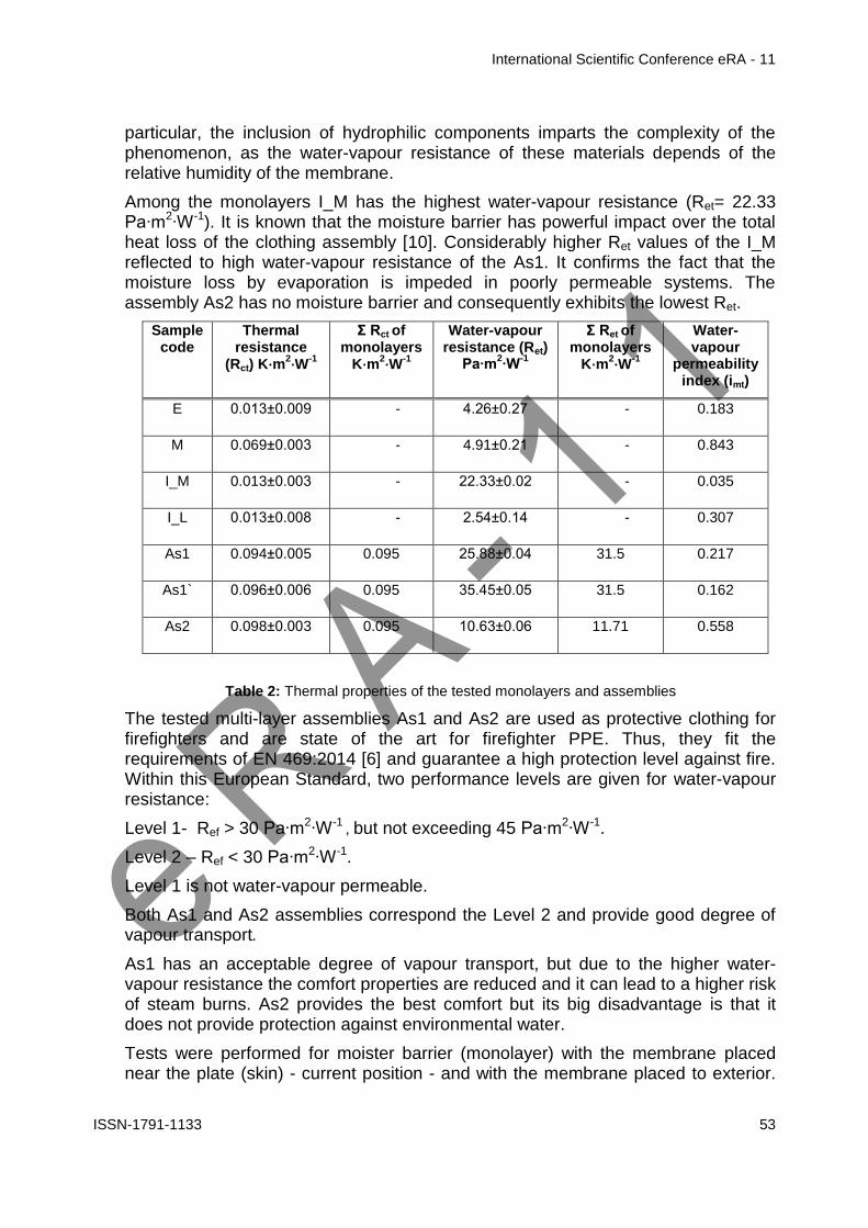
International Scientific Conference eRA - 11
ISSN-1791-1133 62
Considered a case study the ready-to-wear pencil skirt collection made of three different wool-type fabrics selected as suitable for business women the quality evaluation of the comfort features was completed in two stages deploying first a subjective evaluation and second an objective evaluation
In order to make a connection between the subjective evaluation and the objective evaluation the following handle bipolar attributes connected with quality characteristics of fabrics were considered the flexibility stiffness evaluation versus the fabric flexural rigidity measurement the thinness thickness evaluation versus the fabric thickness measurement and the lightness heaviness evaluation versus the fabric weight measurement
For items of clothing for women in business it is expected that besides the aesthetic criteria (insured in terms of fabrics by pattern and colour) there should be rigorous demands imposed regarding the quality of fabrics which must also include the subjectivity feature of the sensory comfort
With this study it was demonstrated once again that for the appropriate results in the product design it is necessary to approach both the sensory comfort estimated during contact when handling a fabric (as a subjective evaluation) and the quality control strategy (as an objective evaluation)
References
[1] Peirce F The handle of cloth as a measurable quality J Textile Inst 1930
[2] Takako I 2002 Objective Evaluation of the Quality of Ladies Garment Fabrics Textile Research Journal Accessed 01092008
[3] Harpa R Hanganu A 2015 Characteristics of Woven Fabrics for Comfortable Summer Dresses - Subjective and Objective Evaluation 15th Autex World Textile Conference 2015 June 10-12 Book of Abstracts
[4] Sztandera M 2012 Identification of the most significant comfort factors for textiles from processing mechanical hand feel fabric construction and perceived tactile comfort data Textile Research Journal 83 pp 34-43 Accessed 13032013
[5] Hollies NRS 1979 A Human Perception Analysis Approach to Clothing Comfort Textile Research Journal 49 pp 557-564 Accessed 17112011
[6] Ellis BC 1980 A Review of Techniques for the Assessment of Hand Textile Research Journal 50 pp 231-238 Accessed 13032013
[7] Kanai H et al 2011 Identification of principal factors of fabric aesthetics by the evaluation from experts on textiles and from untrained consumers Textile Research Journal 81(12) pp 1216-1225 Accessed 13032013
[8] American Association of Textile Chemists and Colourists 2011 AATCC Evaluation Procedure 5-2011 Fabric Hand Guidelines for the Subjective Evaluation of AATCC Technical Manual
[9] Kawabata S Niwa M Wang F Objective Hand Measurement of Nonwoven Fabrics Part I Development of the Equations Textile Research Journal 64 pp 597-610 1994 Accessed 2011
[10] Harpa R 2016 Fabric Hand Approach by Means of Software Package for Teaching Students Part II Software Applications 12th International Scientific Conference eLearning and Software for Education Bucharest April 21-22 2016 Bucharest Romania April 21 - 22 2016 Volume 3