combined natural convection, conduction and °cenidet-dgit
TRANSCRIPT

Combined natural convection, conduction and
radiation heat transfer in a cavity with solar
control coating deposited to a vertical
semitransparent wall
G. Alvarez," C.A. Estrada''
°CENIDET-DGIT-SEP, A.P. 5-164, Cuernavaca, Morelos CP62050, Mexico
>>Laboratorio de Energia Solar-IIM-Unam, A.P. 34, Temixco CP62581, Temixco, Morelos, Mexico
Abstract
This study presents a transient two-dimensional computational model of acombined natural convection, conduction, and radiation in a cavity with anaspect ratio of one containing air as a non participant fluid. The cavity has twoopaque adiabatic horizontal walls, one opaque isothermal vertical wall Theopposite vertical wall is a semitransparent wall that consists of a 6 mm glasssheet with a solar control coating of SnS-Cu*S facing the inside of the cavitypermitting solar radiation exchanges between the cavity and its surroundings'The momentum and energy equations in transient state were solved by finitedifferences using the ADI technique. Coupled to this equations are the transientconduction equation and the radiative energy flux boundary conditions Theresults in this paper are limited to the range of 10*<Gr<10' with an isothermalvertical cold wall of 21°C, outside air temperatures (T.) of 35°C and incidentsolar radiation of AM2 (750 W/m') normal to the semitransparent wall ANusselt number correlation as a function of the Rayleigh number is presented.
1 Introduction
During the last two decades new technologies have been proposed anddeveloped to control the thermal gains through the large window panes of talltower type buildings and hence, to reduce their energy consumption Thetechnology of the solar control coatings is still in progress and is part of thisnew technology. The solar control coatings are used in locations with warmclimates to control in a spectrally selective mode the entrance of sunlight to therooms and thus to reduce the thermal gains inside the building. An importantoptical characteristic of this kind of material is its high absorptance in the solarspectrum which increases the temperature of the solar control coating and glass
Transactions on Engineering Sciences vol 12, © 1996 WIT Press, www.witpress.com, ISSN 1743-3533
176 Advanced Computational Methods in Heat Transfer
This increment of the film and glass temperatures may cause additional thermalgains inside the room instead of reduce them.
Several models has been developed to get a better understanding of thethermal performance in a room, among them, combined natural convectionconduction and radiation in a cavity with opaque walls and non participantmedia appears with Larson in 1972 [4]. Webb and Viskanta [7] presentedexperimental and numerical steady state results of natural convective flowmovement in a cavity with a semitransparent vertical wall and a participantmedia, they considered incident solar radiation. Behnia et al. [2] presented thesame case as before but with a non participant media and no incident radiation.None of those studies have considered the transient process of the heat transferin a cavity with a solar control coating on a semitransparent wall.
As a first approach, to understand the thermal performance of a room witha glass window with solar control coating, a theoretical study of a cavity with asemitransparent wall is presented. This study considers direct insulation,conduction of energy through the semitransparent wall, radiative exchangebetween the walls and a radiatively non participant fluid.
2 Physical Model
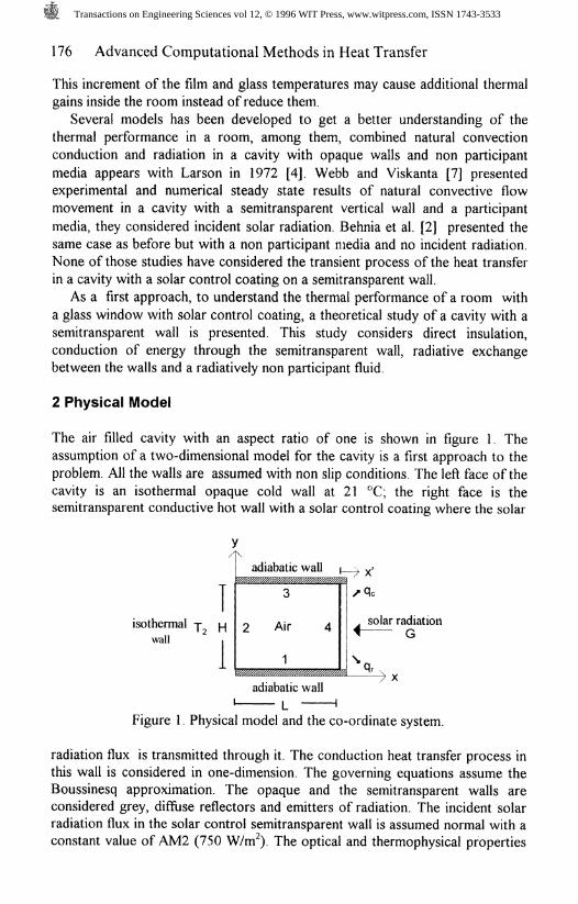
The air filled cavity with an aspect ratio of one is shown in figure 1. Theassumption of a two-dimensional model for the cavity is a first approach to theproblem. All the walls are assumed with non slip conditions. The left face of thecavity is an isothermal opaque cold wall at 21 °C; the right face is thesemitransparent conductive hot wall with a solar control coating where the solar
isothermal j j_|wall
\
2
%2g
adiabatic wall | '
3
Air 4
1%%%%@%%%%%%%%%%%%y
^ sole
2 \
solar radiationG
7 Xadiabatic wall
Figure 1. Physical model and the co-ordinate system.
radiation flux is transmitted through it. The conduction heat transfer process inthis wall is considered in one-dimension. The governing equations assume theBoussinesq approximation. The opaque and the semitransparent walls areconsidered grey, diffuse reflectors and emitters of radiation. The incident solarradiation flux in the solar control semitransparent wall is assumed normal with aconstant value of AM2 (750 W/nf). The optical and thermophysical properties
Transactions on Engineering Sciences vol 12, © 1996 WIT Press, www.witpress.com, ISSN 1743-3533
Advanced Computational Methods in Heat Transfer 177
are considered constant. Although, the solar control coating transmittance andreflectance do depend on the wavelength, in the visible region increases up to40% but in the near infrared region remains constant and its value is less than20%, the optical properties considered here are the integrated spectrum valuesThe air inside the cavity is assumed to be radiatively non-participant for a lowcontent of water vapour. The thickness of the glass is 6 mm with a solar controlcoating of SnS-Cu.S of negligible thickness (<6 urn). The properties are givenin Table 1. The initial temperature is 21°C (294 K).
Table 1. Optical and thermophysical properties of glass and SnS-Cu*S solar
Glass (6 mm)a, =0.14%e 0.78Pa -0.08E%= 0.85
kg = 1.12 W/m K
Glass (3 mm)a* =0.06Tg - 0.86Pe - 0.08
denSg-2500 kg/iif
film (SnS-CuxS)A*soi = 064T*soi = 0.15R*,o, = 0.16
8f = 0.40Cpf=0.750kJ/kgK
Airka = 26.3x10⁻³ VV/mKv= 15.89x10⁻⁶ mVsCpa=1.012kJ/kgKDensa=1.204kg/nr'
3 Mathematical Model
The governing equations are those of the conservation of mass, momentum andenergy equations for a cavity with radiative exchange at the boundaries andconduction in the solar control semitransparent wall. The stream function-vorticity formulation is used. The equations are expressed in a dimensionlessform as:
F^r ^di
-+ V— =5Y Gr^L9X1;
J^aeAT ax
v
i r
Co
(2)
(3)
(4)
JThe dimensionless variables were chosen according to reference [5] as
t=tu,/L, G=T/TH, where
ax* a^
^ + u— + v— =at ax ay
the velocities are related to the streamfunction by
ax
The initial conditions in the cavity are those of a specified uniformtemperature and a stagnant gas. The hydrodynamic boundary conditions are interms or the streamrunction as:
V(0,Y,T) = (j/(l,Y,T) = V(X,0,i) = M/(X,1,T) = 0 (5)The boundary conditions on vorticity are not known explicitly but they are
determined by the Taylor series expansion of the stream function in the vicinity
Transactions on Engineering Sciences vol 12, © 1996 WIT Press, www.witpress.com, ISSN 1743-3533
178 Advanced Computational Methods in Heat Transfer
of the wall. The temperature boundary conditions on the top, bottom andsemitransparent wall are given by the following energy balances:
Energy balance on the bottom insulated wall 1: q% = q% +q^ =0,or
The boundary condition for the isothermal wall 2
T_ T A _ _ 2_- 1 2 / 02 ~ ~^~ I
'HThe boundary condition for the insulated wall 3,
w Q,,= (8)
The temperature boundary condition of the vertical semitransparent wall 4must have careful consideration. The conduction equation for this wall iscoupled to the fluid energy equation by its interior boundary condition. Thus theconduction equation in dimensionless form of wall 4 is
*>.- N. pH), ,dF]
5t N^PrVGrlciX'' dX'J
with F'(X') = N G'exp[-s L'(l-X')], where Sg is the glass extinction
T 3j I s~~\coefficient, N = — - — and G'= - - with the following boundary
k» GT,
conditions:1) energy balance between the inside air and the solar control coatingq absorbed = q k ~ q ka + . ™ dimensionless form
p£\ -. r .-y| a,T.N,G-- -U.,-N,.Q,=0 (10)
2) energy balance between the glass and ambient air
0 (11)
with N, =
ax'L'h
* kgThe local Nusselt number in dimensionless form is given by
Nu = .8,-8, 5X
The dimensionless temperature of the vertical wall opposite to the verticalsemitransparent wall is specified as 6(0,Y)=0.84 which corresponds to 21°C(294 K) for a TH of 1TC (350 K). The terms Q,, Q^, Q^ yQ, are the
dimensionless radiative fluxes inside the walls of the cavity given by theradiative transfer equations. For a grey diffusive walls with an arbitrarytemperature distribution, the radiation configuration factors between any pair of
Transactions on Engineering Sciences vol 12, © 1996 WIT Press, www.witpress.com, ISSN 1743-3533
Advanced Computational Methods in Heat Transfer 179
elements of the boundary must be determined. The radiative heat flux alone thewall us given by q, = J,(x,)-q.(x,) f^
with J,(x,) = 8,oT/+p,q,(x.) and q,(x,) = £ Jj,(r,)dF_, (14)J=> Aj
where q,(x,) is the incoming radiative heat flux of the wall i and J is theradiosity. The configuration factors Fy are already given in reference [51Solving the radiosity equations, dimensional values are used in the calculationof the radiative fluxes on the boundaries and the result is non-dimensionalized.
4 Method of Solution
Equations (l)-(4), conduction equation (9) along with the radiative fluxequations (13)-(14) and their initial and boundary conditions (5)-(l 1) define theproblem completely. The derivatives of the partial differential equations (1)and (3) were approximated by forward time and central space differences, theADI (Alternatmg-Direction-Implicit) finite differences method was used Thestreamline equation (2) was solved by the method of Paceman and RachfordI he conduction differential equation was solved numerically by using aexplicit finite differences formulation. The net radiative heat fluxes werecalculated from the radiative net heat flux equation (13); the radiosity equationswere solved by the method of successive approximation. The integrals wereevaluated by the Simpson's rule.
The solution procedure goes in the following order. Knowing the initial andboundary values, the radiative net heat flux is computed. As solar energyradiation strikes the glass and film, the energy conduction equation (9) for theglass and their boundary conditions (10) and (11) are solved to update thetemperature distribution in the glass. The normal temperature gradients areca culated from equations (6) and (8). The partial differential equation (3) issolved to obtain the inside air temperature patterns, then the vorticity-transportequation (1) and the stream function equation (2). After that, the velocity fieldis calculated from equations (4). The procedure is repeated until steady state isreached.
5 Results
Several numerical experiments were tested to determine the time step gridsize and convergence criteria. For Or of 10* and 10*, a mesh of 31x31 nodalpoints and a time increment of 0.001 were adequate in terms of accuracy andcomputed economy. For Gr=10« a mesh of 51x51 and a time increment of0.0005 were satisfactory but the computer time increases appreciably Also tovalidate the model, a comparison with the classical problem of naturalconvection m a cavity with isothermal vertical walls was carried out Thecomparison was satisfactory [1]. The parameter values used were for a squarecavity containing air with an ambient exterior temperature of 35°C, an external
Transactions on Engineering Sciences vol 12, © 1996 WIT Press, www.witpress.com, ISSN 1743-3533
180 Advanced Computational Methods in Heat Transfer
convective heat transfer of 6.2 W/m^ °C. All the surface walls were assumed tohave an emittance of 0.9 except for the semitransparent wall, which has aninside film emittance of 0.4 and an exterior glass emittance of 0.85.
To examine the effects of the use of the solar control coating on thesemitransparent wall, two cases were considered, case A; a cavity with asemitransparent wall of glass and film and case B; the same as case A exceptthat the semitransparent wall is a clear glass. The semitransparent wall is locatedon the right side of the cavity.
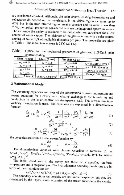
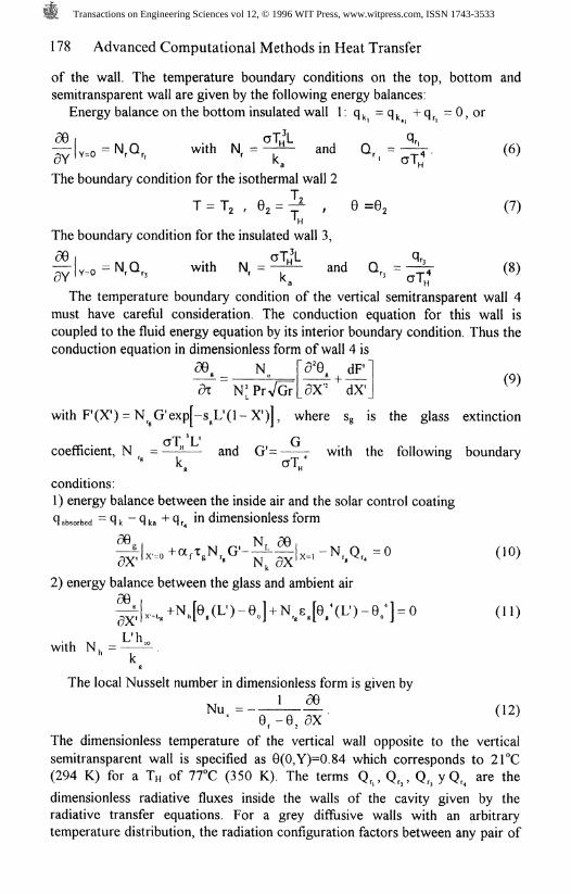
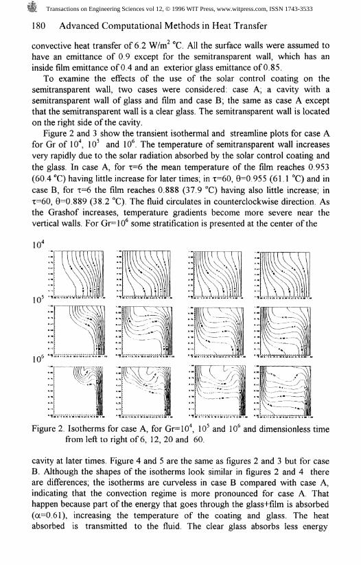
Figure 2 and 3 show the transient isothermal and streamline plots for case Afor Gr of 10*, 10^ and 10*. The temperature of semitransparent wall increasesvery rapidly due to the solar radiation absorbed by the solar control coating andthe glass. In case A, for 1=6 the mean temperature of the film reaches 0.953(60.4 °C) having little increase for later times; in T=60, 0=0.955 (61.1 T) and incase B, for 1=6 the film reaches 0.888 (37.9 °C) having also little increase; inx=60, 0=0.889 (38.2 °C). The fluid circulates in counterclockwise direction. Asthe Grashof increases, temperature gradients become more severe near thevertical walls. For Gr=10* some stratification is presented at the center of the
Figure 2. Isotherms for case A, for Gr=10\ 10* and \(f and dimensionless timefrom left to right of 6, 12, 20 and 60.
cavity at later times. Figure 4 and 5 are the same as figures 2 and 3 but for caseB. Although the shapes of the isotherms look similar in figures 2 and 4 thereare differences; the isotherms are curveless in case B compared with case A,indicating that the convection regime is more pronounced for case A. Thathappen because part of the energy that goes through the glass+film is absorbed(a=0.61), increasing the temperature of the coating and glass. The heatabsorbed is transmitted to the fluid. The clear glass absorbs less energy
Transactions on Engineering Sciences vol 12, © 1996 WIT Press, www.witpress.com, ISSN 1743-3533

Advanced Computational Methods in Heat Transfer 181
10*
10*
Figure 3. Streamlines for case A, for Gr=10\ 10* and 10* and dimensionlesstime from left to right of 6, 12, 20 and 60.
(a-0.14). The thermal boundary layer thickness of cases A and B for Gr=10*and 10* in the lower side of the cavity is thinner for the case A than for the caseB, but the isotherms in the upper side are curveless in case B compared with A,indicating that the diffusion is slower towards the core of the cavity.
10'
10"
Figure 4. Isotherms for case B, for Gr=10*, 10* and 10* and dimensionless timefrom left to right of 6, 12, 20 and 60.
Transactions on Engineering Sciences vol 12, © 1996 WIT Press, www.witpress.com, ISSN 1743-3533

182 Advanced Computational Methods in Heat Transfer
Figure 5. Streamlines for case B, for Gr=lO\ 10^ and 10* and dimensionlesstime from left to right of 6, 12, 20 and 60.
Looking at figures 3 and 5, one vortex is presented in most of the casesexcept for Gr= 10* for times of 20 and 60 where two vortex are appreciated.Initially the vortex is located towards the upper right side of the cavity then itmoves to the center of the cavity. For Gr=10^ the central streamline is elongatedand distorted in an elliptic shape. The effect of convection is more pronouncedin this case than in Gr=10*. The streamline gradients are stronger in case A thanin case B indicating the influence of the radiative heat flux which makes thefluid moves slower. For Gr=10*, the streamline patterns for cases A and B, thevortices move closer to the walls and are convected downstream. The boundarylayers adjacent to the vertical walls become thin and fast. In figure 3, for Gr=10*and 1=6 the flow spreads out from a thin layer in the vertical wall and turns overthe corner, as the flow turns over, it starts to separate from the wall and thenreattached to it, this effect is not shown for case B for x=6 but for the nexttimes the effect is more pronounced for the two cases. This oscillation has beenalready reported in natural convection cavities [3,6] and not in combined naturalconvection and radiation.
A correlation for the average Nusselt number were derived using least squarelinear regression for 1x10* < Gr < 5 x 10* and Pr=0.73. The correlation is:
Nue = 0.0643 (Pr Gr) " for Pr=0.73 and 1x10* < Gr < 5 x 10*
Using arguments of energy balance in the cavity, it was found that, thepercentage difference was less than 4% (3.75%), showing a possible totalnumerical error less than this number
Transactions on Engineering Sciences vol 12, © 1996 WIT Press, www.witpress.com, ISSN 1743-3533
Advanced Computational Methods in Heat Transfer 183
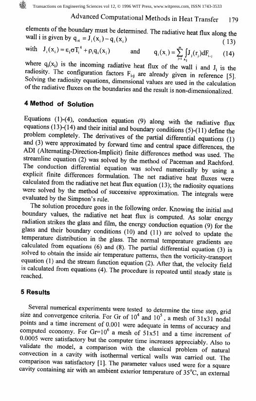
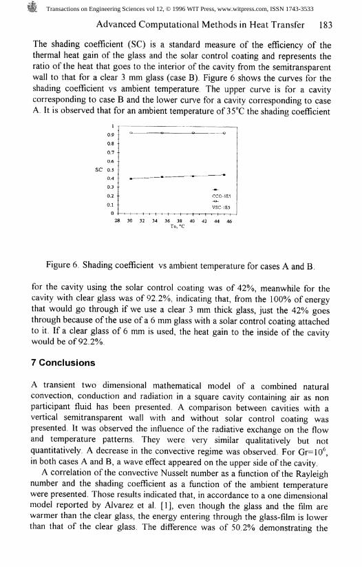
The shading coefficient (SC) is a standard measure of the efficiency of thethermal heat gain of the glass and the solar control coating and represents theratio of the heat that goes to the interior of the cavity from the semitransparentwall to that for a clear 3 mm glass (case B) Figure 6 shows the curves for theshading coefficient vs ambient temperature. The upper curve is for a cavitycorresponding to case B and the lower curve for a cavity corresponding to caseA. It is observed that for an ambient temperature of 35°C the shading coefficient
0.90.80.7 •0.6
SC 0.50.40.3 -0.2 -0.10 -1*
CCO-1E5VSC-1E5
* 30 32 34 36 38 40 42 44 46
Figure 6. Shading coefficient vs ambient temperature for cases A and B.
for the cavity using the solar control coating was of 42%, meanwhile for thecavity with clear glass was of 92.2%, indicating that, from the 100% of energythat would go through if we use a clear 3 mm thick glass, just the 42% goesthrough because of the use of a 6 mm glass with a solar control coating attachedto it. If a clear glass of 6 mm is used, the heat gain to the inside of the cavitywould be of 92.2%.
7 Conclusions
A transient two dimensional mathematical model of a combined naturalconvection, conduction and radiation in a square cavity containing air as nonparticipant fluid has been presented. A comparison between cavities with avertical semitransparent wall with and without solar control coating waspresented. It was observed the influence of the radiative exchange on the flowand temperature patterns. They were very similar qualitatively but notquantitatively. A decrease in the convective regime was observed. For Gr=10^,in both cases A and B, a wave effect appeared on the upper side of the cavity.
A correlation of the convective Nusselt number as a function of the Rayleighnumber and the shading coefficient as a function of the ambient temperaturewere presented. Those results indicated that, in accordance to a one dimensionalmodel reported by Alvarez et al. [1], even though the glass and the film arewarmer than the clear glass, the energy entering through the glass-film is lowerthan that of the clear glass. The difference was of 50.2% demonstrating the
Transactions on Engineering Sciences vol 12, © 1996 WIT Press, www.witpress.com, ISSN 1743-3533

184 Advanced Computational Methods in Heat Transfer
clear advantage, from the thermal point of view, of the use of the solar controlcoating on glass windows.
Nomenclature
LatinsA*GOrh«kNO.NkNuPrR*soiTtX,YGreeksa
Solar absorptancc, % CpIncident Solar radiation, W/m^ gGrashof number, gpATL%* HHeat transfer coefficient, W/rn K Jjthermal conductivity, W/m K L, L'Dimensionless param. otg/ a NHDimensionless param. kw/k, NLNusselt number, hL/k, qPrandtl number, u/a R*,<>iIntegrated Reflectance, % s,Temperature, K T *,«!time, s II, VDimensionless coord, directions
Air diffiisivity, mVs a,Thermal expansion coefficient, 1/K 8Kinematic viscosity, mVs PJDimensionless temperature, T/Tn vyVorticity tgDimensionless time, tu /L a
Index
f,4g
incident energy on wall i afilm Hglass I
Specific heatGravity, m/sHeight of cavity, mRadiosity of wall i,Wide of the cavity, Thickness of glass, mDimensionless param. hL'/kgDimensionless parameter, LVLHeat, W/m*Integrated Reflectance, %Extinction coefficient of glass, 1/mIntegrated transmittance, %Dimensionless velocity,u/u<,
Glass absorptanceEmittanceReflectance of wall iStreamlinesGlass transmissivityStefan Boltzm. const., W/m*
airhighest temperatureinside
net radiation on wall iconductionoutside
References
1. Alvarez, G. Transferencia de Calor en una Cavidad con InteractionTermica a Traves de una Cara Semitransparente con Controlador Optico,Doctor in Engineering Thesis, National University of Mexico, 1994.
2. Behnia, M., J A Rizes & G de Vahl Davis. Combined Radiation andNatural Convection in a Cavity with a Semitransparent Wall and Containinga Non-participant Fluid, Int. J. for Numerical methods in Fluids, 1990, 10,305-325.
3. Ivey, G.N. Experiments on Transient Natural Convection in a cavity, J. ofFluid Mech. 1984, 144, 389-401.
4. Larson, D.W. Analytical Study of Heat Transfer in an Enclosure, Ph.D.Thesis, Purdue University, 1972.
5. Larson, D.W & R. Viskanta. Transient Combined Laminar Free Convectionand Radiation in a Rectangular Enclosure, J. Fluid Mechanics, 1976, 78,65-85.
6. Ravi, MR, RAW Henkes & J. Hoogendoon. On the High RayleighNumber Structure of Steady Laminar Natural Convection Flow in SquareEnclosure, J. FluidMech., 1994, 262, 325-351.
7. Webb, B.W. & R Viskanta. Radiation Induced Buoyancy Driven Flow inRectangular Enclosures: Experiment and analysis, J. of Heat Transfer,1987, 109,427-433.
Transactions on Engineering Sciences vol 12, © 1996 WIT Press, www.witpress.com, ISSN 1743-3533