hounÖ introduction combislim service and installation manual cpe 5 introduction dear customer,...
TRANSCRIPT

HOUNÖ Service and Installation Manual CombiSlim II CPE
ENG Version 1.1 x 10-2014

2 COMbISlIM SERVICE aNd INStallatION MaNUal CPE
INtROdUCtION
5
lOCatING tHE SERIal NUMbER Of tHE OVEN
6
INStallatION aNd CONNECtION
7Unpacking the oven 7
Installing the Oven 8Oven Dimensions 8
CONNECtING
9Connecting to Water Supply 9
Connecting to the Drain 10
ElECtRICal CONNECtIONS
12CombiSlim 23.06 Electical Connections 12
CombiSlim 1.06 Electical Connections 13CombiSlim 1.10 Electical Connections 13
Extraction hood for all CombiSlim models 13
WIRING dIaGRaM
14
ExHaUSt
17
CHECkING bEfORE USE
18Basic Operations 19
SEttINGS MENU
20
CHaNGING SEttINGS ON tHE USER MENU
21Setting the Oven Light 21
Setting the Screen Saver 21Setting the Language 21
Setting the Setup Clock 22Viewing the Software Version 22
tablE Of CONtENtS

COMbISlIM SERVICE aNd INStallatION MaNUal CPE 3
CHaNGING SEttINGS ON tHE SUPERUSER dISPlay
23
Setting Alarm Sounds 23Changing Settings 25
Adjustments 27Calibrating the Oven Door Sensor 29
Logs and Statistics 30
SEttINGS ON tHE tECHNICIaN MENU
31Using the Test Functions 31
Making Temperature Adjustments 35Changing Oven Settings 36
Making Corrections to Bake Time 37Specifying Middle East Specific Settings 37
Enabling Demo mode 38
tROUblESHOOtING
39General Error Codes 39
SafEty
47
SERVICE aNd REPaIR
48
WaRRaNty
49Excluded from Warranty 49
tablE Of CONtENtS

4 COMbISlIM SERVICE aNd INStallatION MaNUal CPE

INtROdUCtION
COMbISlIM SERVICE aNd INStallatION MaNUal CPE 5
INtROdUCtIONDear customer,
Thank you for choosing a CombiSlim oven from HOUNÖ.
This manual contains the information you need to service and maintain your oven. We recommend that you read the manual and familiarize yourself with the service settings and functions of the oven. This will ensure optimal cooking results and safety. lease make the manual available to all who service and maintain the oven and retain it for future reference. The latest version of the manual can be downloaded from www.houno.com.
Note that this document is subject to change without notice.

lOCatING tHE SERIal NUMbER Of tHE OVEN
6 COMbISlIM SERVICE aNd INStallatION MaNUal CPE
lOCatING tHE SERIal NUMbER Of tHE OVENWhen you order parts or request service for your CombiSlim oven, you need the oven’s Serial Number,
You can find the Serial Number and Type information on the right-hand corner post of the oven as shown in the illustration.

INStallatION aNd CONNECtION
COMbISlIM SERVICE aNd INStallatION MaNUal CPE 7
INStallatION aNd CONNECtION
Unpacking the oven
The oven is best handled while still in its wrapping. Wherever possible, use a lifting trolley.
Remove the original packaging from the oven. Do not remove the foil that covers the surfaces until the oven has been installed, as once the foil has been removed the surfaces are vulnerable to sharp objects such as tools.
The packaging should be destroyed in accordance with national rules and regulations governing waste disposal. Information on the compo-sition of the packaging material can be obtained from the HOUNÖ Customer Centre.

INStallatION aNd CONNECtION
8 COMbISlIM SERVICE aNd INStallatION MaNUal CPE
Installing the Oven
Strong sources of heat such as hotplates, tilting frying pans, deep fat fryers, etc. should not be placed near the oven, minimum distance to such appliances should be 1,000 mm, otherwise the warranty may cease to apply. This is to ensure the necessary flow of cooling air to the oven.
At least 50 mm/ 2 inches clearance from the rear wall is required at the back of the oven.
Oven dimensions
Oven Type Weight, kg
Height with stand x width x depth* -millimeters
23.06 57 kg 1565 x 513 x 631 mm
1.06 67 kg 1565 x 513 x 811 mm
1.10 81 kg 1765 x 513 x 811 mm
*Heights may vary depending on stand configuration

CONNECtING
COMbISlIM SERVICE aNd INStallatION MaNUal CPE 9
CONNECtING
Connecting to Water Supply
CombiSlim ovens have one water connection.
To facilitate cleaning and service, the oven should be connected with an approved flexible ¾’’ hose and the permanent installations should be fitted with a stop tap.
Flush the tubes thoroughly before you connect the oven to the water supply.
Plumbing Specifications
• Hardness of the water: max. 3 dH
• Water pressure: min 2.5 bar (36 PSI) dynamic pressure when using CombiWash max. 6 bar (87 PSI)
• Water flow: min 12 l/m
• Water temperature: max 20°C (68°F)
• Chloride concentration mas. 100 mg/liter
• Sulphate: max. 150 mg/liter
If the water feeder is connected to the water supply with a flexible connection hose, the hose should comply with local rules and regulations.

CONNECtING
10 COMbISlIM SERVICE aNd INStallatION MaNUal CPE
The water supply connection must be carried out by an authorized plumber in compliance with local rules and regulations.
The warranty does not cover clogged up water filers or dirt in the solenoid valves.
To ensure that the water quality conforms to the above requirements, we recommend that you install a water filter in front of the water connection.
We recommend that you install a 0.25 mm particle filter.
Connecting to the drain
From the factory, the CombiSlim oven comes equipped with a drains system that removes surplus water from the oven chamber. Surplus water may be condensed water from the products, water from the cool down process when the oven chamber is cooled down with cold water, or water from cleaning of the oven chamber.
A licensed plumber must perform the connection to the drain.
We recommend that there is a water outlet in the floor of the room where the oven is located.
The drain must never end directly under the oven.

CONNECtING
COMbISlIM SERVICE aNd INStallatION MaNUal CPE 11
Drain specifications
• The drain must be made of stainless steel or an equally temperature-resistant material.
• The drain must have a diameter of at least 40 mm/ 2 inches.
• The drain must have a fall of at least 3° or 5%.

ElECtRICal CONNECtIONS
12 COMbISlIM SERVICE aNd INStallatION MaNUal CPE
ElECtRICal CONNECtIONS
A licensed electrician must perform the installation in compliance with local rules and regulations.
• The wiring diagram is located in the electrical compartment under the top cover.
• The terminals for the electrical connection is located behind the real cover plate.
To ensure that the oven can be disconnected during installation and repair, an approved plug outlet or safety cut-out must be located close to the oven. The safety cut-out must be able to automatically cut off all poles with a total distance of break of at least 3 mm. Each of the two units in a stacked arrangement (CombiPlus) must have its own plug outlet or safety cut-out.
Improper electrical installation will invalidate your warranty.
CombiSlim 23.06 Electical Connections
Config-uration Power kW Phase kW Hz Amp Fuse Heating
elementsPhase 1
Phase 2
Phase 3 Neutral mm2 El diagram
nr.
1.
208/230/240 1NAC 2,7/3,3/3,6 50/60 15 16 30700041 15 -- -- 15 2.5 31000049
208/230/240 2AC 2,7/3,3/3,6 50/60 15 16 30700041 15 15 -- -- 2.5 31000049
208/230/240 3AC 5,4/6,6/7,2 50/60 30 35 30700041 15 15 30 -- 4 31000049
400/415 2NAC 6,6/7,2 50/60 15 16 30700041 15 15 -- 15 2.5 31000049
2. 400/415 2AC 5,4/5,8 50/60 15 16 30700042 15 15 -- -- 2.5 31000080
3. 440/480 2AC 5,4/6,5 50/60 15 16 30700043 15 15 -- -- 2.5 31000080
ElECtRICal CONNECtIONS
COMbISlIM SERVICE aNd INStallatION MaNUal CPE 13
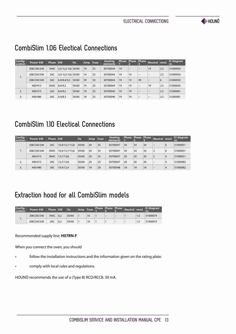
CombiSlim 1.06 Electical Connections
Config-uration Power kW Phase kW Hz Amp Fuse Heating
elementsPhase 1
Phase 2
Phase 3 Neutral mm2 El diagram
nr.
1.
208/230/240 1NAC 3,5/ 4,2/ 4,6 50/60 19 25 30700044 19 -- -- 19 2.5 31000050
208/230/240 2AC 3,5/ 4,2/ 4,6 50/60 19 25 30700044 19 19 -- -- 2.5 31000050
208/230/240 3AC 6,9/8,4/9,2 50/60 39 50 30700044 19 19 39 -- 6 31000050
400/415 2NAC 8,4/9,2 50/60 19 25 30700044 19 19 -- 19 2.5 31000050
2. 400/415 2AC 8,4/9,2 50/60 19 25 30700045 19 19 -- -- 2.5 31000081
3. 440/480 2AC 6,9/8,3 50/60 18 25 30700046 19 19 -- -- 2.5 31000081
CombiSlim 1.10 Electical Connections
Config-uration Power kW Phase kW Hz Amp Fuse Heating
elementsPhase 1
Phase 2
Phase 3 Neutral mm2 El diagram
nr.
1.
208/230/240 3AC 10,4/12,7/13,8 50/60 34 35 30700047 34 34 34 -- 6 31000051
208/230/240 3NAC 10,4/12,7/13,8 50/60 34 35 30700047 34 34 34 2 6 31000051
400/415 3NAC 12,7/13,8 50/60 20 25 30700047 20 20 20 2 4 31000051
2. 400/415 3AC 12,7/13,8 50/60 20 25 30700047 20 20 20 -- 4 31000082
3. 440/480 3AC 10,4/12,4 50/60 18 20 30700048 18 18 18 -- 4 31000082
Extraction hood for all CombiSlim models
Config-uration Power kW Phase kW Hz Amp Fuse Phase
1Phase 2
Phase 3 Neutral mm2 El diagram
nr.
1.208/230/240 1NAC 0,2 50/60 1 10 1 -- -- 1 1,5 31000074
208/230/240 2AC 0,2 50/60 1 10 1 1 -- -- 1,5 31000074
Recommended supply line: H07RN-F
When you connect the oven, you should
• followtheinstallationinstructionsandtheinformationgivenontheratingplate.
• complywithlocalrulesandregulations.
HOUNÖ recommends the use of a (Type B) RCD/RCCB. 30 mA.

WIRING dIaGRaM
14 COMbISlIM SERVICE aNd INStallatION MaNUal CPE
WIRING dIaGRaMThis is how the CombiSlim ovens should be connected according to voltage:
CS 2306 208-415V 1-3NAC
CS 106 208-415V 1-3NAC
NL2 L3L1
208/230/240V 1NAC208/230/240V 2AC
3,5/4,2/4,6 kW
L1 N
NL2 L3L1
208/230/240V 3AC6,9/8,4/9,2 kW
L2 L3L1 N
NL2 L3L1
400/415V 2NAC8,4/9,2 kW
L2L1 N
CHECK IF INPUT ONTRANSFORMER ARE SET
FOR CORRECT INPUTVOLTAGE.
T1
208-
240
VAC
0 11,5
24 0 24
0
208200
230
240
Connection mustfollow input voltage
208V = 208230V = 230240V = 240400V = 230415V = 240
37000050.00CSII 106 208-415V 1-3NAC HE1
NL2 L3L1
208/230/240V 1NAC208/230/240V 2AC
2,7/3,3/3,6 kW
L1 N
NL2 L3L1
208/230/240V 3AC5,4/6,6/7,2 kW
L2 L3L1 N
NL2 L3L1
400/415V 2NAC6,6/7,2 kW
L2L1 N
CHECK IF INPUT ONTRANSFORMER ARE SET
FOR CORRECT INPUTVOLTAGE.
T1
208-
240
VA
C
0 11,5
24 0 24
0
208200
230
240
Connection mustfollow input voltage
208V = 208230V = 230240V = 240400V = 230415V = 240
37000049.00CSII 2306 208-415V 1-3NAC HE1
WIRING dIaGRaM
COMbISlIM SERVICE aNd INStallatION MaNUal CPE 15
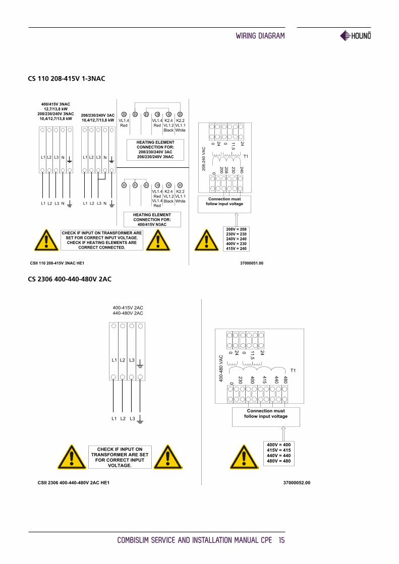
CS 110 208-415V 1-3NAC
T1
208-
240
VA
C
0 11,5
24 0 24
0
208200
230
240
Connection mustfollow input voltage
208V = 208230V = 230240V = 240400V = 230415V = 240
37000051.00CSII 110 208-415V 3NAC HE1
NL2 L3L1
400/415V 3NAC12,7/13,8 kW
208/230/240V 3NAC10,4/12,7/13,8 kW
L1 N
NL2 L3L1
208/230/240V 3AC10,4/12,7/13,8 kW
L2 L3L1 NL2 L3
HEATING ELEMENTCONNECTION FOR:
400/415V N3AC
HEATING ELEMENTCONNECTION FOR:208/230/240V 3AC
208/230/240V 3NAC
CHECK IF INPUT ON TRANSFORMER ARESET FOR CORRECT INPUT VOLTAGE.CHECK IF HEATING ELEMENTS ARE
CORRECT CONNECTED.
VL1.4Red
VL1.4Red
K2.2VL1.1White
K2.4VL1.2Black
VL1.4Red
K2.2VL1.1White
K2.4VL1.2BlackVL1.4
Red
CS 2306 400-440-480V 2AC
CHECK IF INPUT ONTRANSFORMER ARE SET
FOR CORRECT INPUTVOLTAGE.
Connection mustfollow input voltage
400V = 400415V = 415440V = 440480V = 480
37000052.00CSII 2306 400-440-480V 2AC HE1
L2 L3L1
L2 L3L1
400-415V 2AC440-480V 2AC
400-
480
VAC
0 11,5
24 0 24
0
230
400
T1
415
440
480
WIRING dIaGRaM
16 COMbISlIM SERVICE aNd INStallatION MaNUal CPE
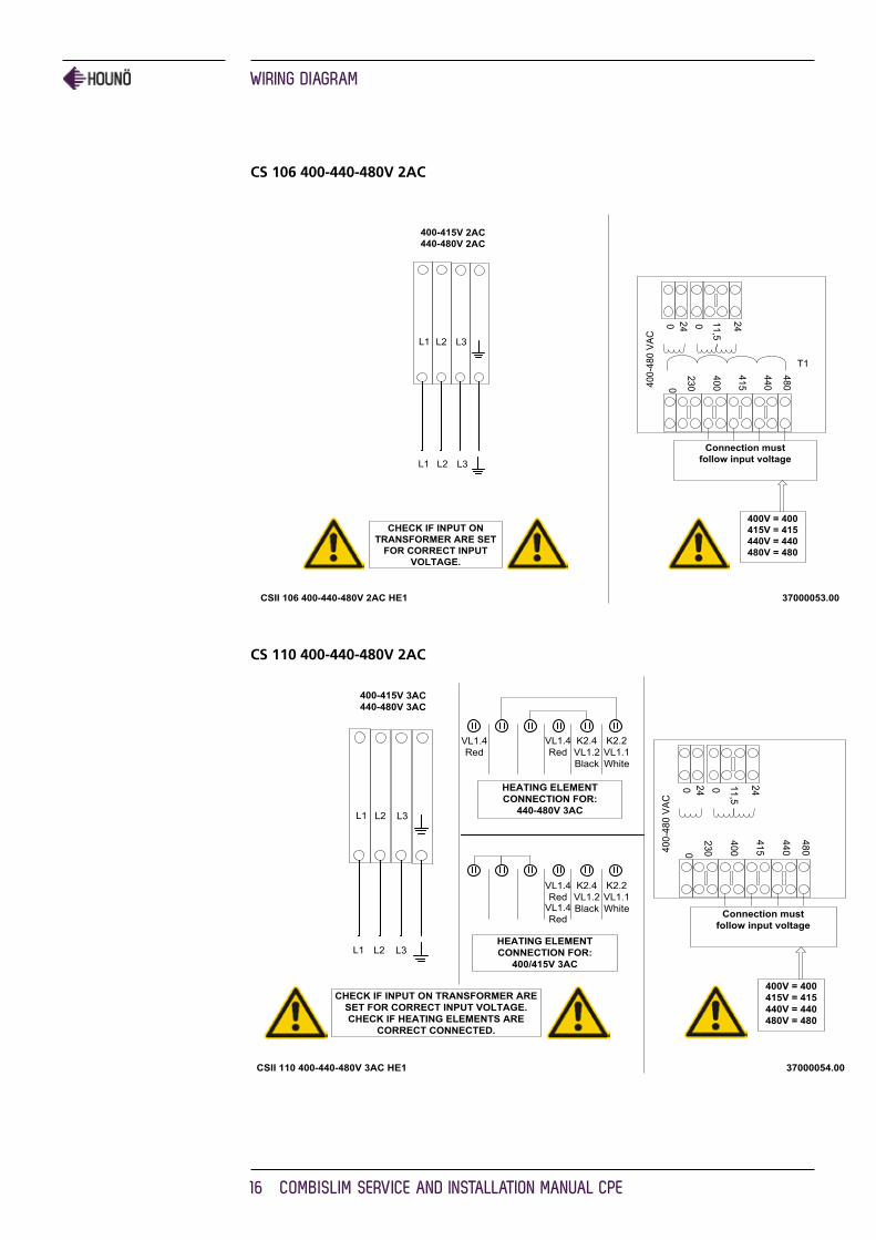
CS 106 400-440-480V 2AC
CHECK IF INPUT ONTRANSFORMER ARE SET
FOR CORRECT INPUTVOLTAGE.
Connection mustfollow input voltage
400V = 400415V = 415440V = 440480V = 480
37000053.00CSII 106 400-440-480V 2AC HE1
L2 L3L1
L2 L3L1
400-415V 2AC440-480V 2AC
400-
480
VAC
0 11,5
24 0 24
0
230
400
T1
415
440
480
CS 110 400-440-480V 2AC
37000054.00CSII 110 400-440-480V 3AC HE1
HEATING ELEMENTCONNECTION FOR:
440-480V 3AC
CHECK IF INPUT ON TRANSFORMER ARESET FOR CORRECT INPUT VOLTAGE.CHECK IF HEATING ELEMENTS ARE
CORRECT CONNECTED.
Connection mustfollow input voltage
400V = 400415V = 415440V = 440480V = 480
400-
480
VAC
0 11,5
24 0 24
0
230
400
415
440
480
L2 L3L1
L2 L3L1
400-415V 3AC440-480V 3AC
HEATING ELEMENTCONNECTION FOR:
400/415V 3AC
VL1.4Red
K2.2VL1.1White
K2.4VL1.2Black
VL1.4Red
K2.2VL1.1White
K2.4VL1.2BlackVL1.4
Red
VL1.4Red

ExHaUSt
COMbISlIM SERVICE aNd INStallatION MaNUal CPE 17
ExHaUStThe HOUNÖ ovens are equipped with an open/direct exhaust system that removes surplus humidity from the oven chamber. The exhaust system has an electrically operated damper.
The exhaust tube can be connected to a ventilating system. In that case, a special extraction funnel is fitted to avoid suction directly from the oven chamber. This extraction funnel can be ordered from HOUNÖ.
The scope of supply also includes a specially designed extraction hood, see illus. below.
If an extraction hood is installed in the ceiling above the oven, it should project 50 cm over the front of the oven. The suction effect should be 400 – 800 m3/h.
The installation of the ventilation must be carried out in compliance with national rules and regulations.

CHECkING bEfORE USE
18 COMbISlIM SERVICE aNd INStallatION MaNUal CPE
CHECkING bEfORE USEThe oven should be checked before you start using it.
On the outside
• Checkthattheovenhasnotbeendamagedintransit(dents,scratches,etc.)
• Check/adjusttheheightandcheckthattheovenisplacedlevel(horizontally)
• Check/adjustovendoor
Connections
• Checkforcorrectwaterconnection
• Turnonwatersupply
• Checkforleaks
• Turnoffwatersupply
• Checkandcleandirtfilter
• Turnonwatersupplyagain
• Checkhandshower
• Checkforcorrectelectricalconnection
• Checkconnectiontodriptray
• Checkforcorrectmountingofdriptray
• Checkforcorrectfallofhosefromdriptray,andcheckforleaks
• Checkforcorrectexhaustanddrainconnection
• Cleantheoven
• Applysteeloil
Oven chamber
• Checkthatfilterhousingismountedcorrectly
• Checkinteriorlight
• Cleantheoven
Operation panel
• Checkandadjust,ifnecessary,eachofthepresetvalues
• Heatuptheovenat250°Cforapprox.5min.
The installation checklist and the instruction checklist (appendices 1 and 2) should be filled in and returned to HOUNÖ 30 days after the installation, at the latest.

CHECkING bEfORE USE
COMbISlIM SERVICE aNd INStallatION MaNUal CPE 19
USING tHE SMaRttOUCH® dISPlayThe SmartTouch display provides a friendly and easy way for you to operate and interact with the CombiSlim oven. You simply use the pads of your fingertips to perform the opera-tions.
basic Operations
• To select an item, touch the button.
• To scroll through a list, drag your finger up or down.
• To return to the previous display push the arrow button in the upper left corner.
• To change cooking function while the oven is operating, push the down arrow button in the upper right corner.
• To save current settings and move on to the next step, push the right arrow button in the upper right corner.

SEttINGS MENU
20 COMbISlIM SERVICE aNd INStallatION MaNUal CPE
SEttINGS MENUBefore you can start the maintenance process or change settings, you have to open the Settings Menu.
• On the Main Menu, touch the gear wheel icon to enter the Settings Menu.
Role Access rights
User Access to the User menu
SuperUser Access to the User and SuperUser menus
Technician Access to User, SuperUser, and Technician menus
The settings you have access to depend on the role you have been assigned.
SuperUser Code
If start-up permission is set to User, you have to enter the SuperUser code to gain access to the SuperUser menu.
1. On the Main Menu, touch the key icon .
2. On the Choose menu, touch the key icon , and then enter the code. The code is 876412.
Technician Code
If start-up permission is set to User or SuperUser, you have to enter the Technician code to gain access to the Technician menu.
1. On the Main Menu, touch the key icon .
2. On the Choose menu, touch the key icon , and then enter the code. The code is 576021.
Note The computer has been thoroughly tested by the manufacturer prior to delivery, and the settings have been carefully reviewed. You should therefore only allow qualified personnel to make changes to the settings. Contact your supplier for more information.

CHaNGING SEttINGS ON tHE USER MENU
COMbISlIM SERVICE aNd INStallatION MaNUal CPE 21
CHaNGING SEttINGS ON tHE USER MENUYou change the basic settings from the User Menu.
• On the Settings Menu, touch the User button.
Setting the Oven light
1. To set oven light, touch Oven light.
2. Drag your finger up or down to select Continuous or 5 min., and then touch OK.
Setting the Screen Saver
1. To set the screen saver, touch Screen saver.
2. Drag your finger up or down to select the desired setting. Select how much time elapses before the screen saver becomes active. Select Off if you do not want the screen saver on.
3. Touch OK.
Setting the language
1. To set the language, touch Language.
2. Drag your finger up or down to select the desired language, and then touch OK.

CHaNGING SEttINGS ON tHE USER MENU
22 COMbISlIM SERVICE aNd INStallatION MaNUal CPE
Setting the Setup Clock
1. To set the clock, touch Setup clock.
2. In the hour and min. lists drag your finger up or down to select the desired time.
3. In the day, month and year lists drag your finger up or down to select the desired date.
4. Touch OK.
Viewing the Software Version
The current software version is displayed on the Software version button.
• To view which software version is installed touch Software version.

CHaNGING SEttINGS ON tHE SUPERUSER dISPlay
COMbISlIM SERVICE aNd INStallatION MaNUal CPE 23
CHaNGING SEttINGS ON tHE SUPERUSER dISPlayYou can access the following areas on the super user display.
• Sounds
• Settings
• Adjustments
• Calibrate
• Logs and statistics
• USB system report
• Install new software
• Restart oven
Setting alarm Sounds
You can have the CombiSlim oven play a sound (alarm) when certain events occur. You have a number of options when you assign a sound to an event. It is possible to adjust, among other things, the volume and the time elapsed between each reminder.
1. On the SuperUser display, touch Sounds.
2. To change a sound, touch the event that you want to assign a sound for. The following events are available:
• Finished
• Recipe notification
• Racktimer finish
• Door open
• Probe missing
• Insert product
• Error
• Timer start

CHaNGING SEttINGS ON tHE SUPERUSER dISPlay
24 COMbISlIM SERVICE aNd INStallatION MaNUal CPE
3. Set the desired sound properties. For each event, you can specify the following properties.
Property What it does
Sound Set Used to select the desired sound set for the alarm. The default sound set is Android.
Sound File Used to select the specific sound from the set. You can then test the sound by touching the Test Sound button.
Repeat Used to specify for how many times the alarm should be repeated.
Start repeat delay Used to specify the interval between the first and the second sounding of the alarm.
End repeat delay Used to specify the interval between the second to last and the final sounding of the alarm.
End repeat delay after
Used to specify the interval between the sounding of the alarm after the first sounding of the alarm.
Start volume Used to specify the volume at the first sounding of the alarm.
End volume Used to specify the volume after the final sounding of the alarm.
End volume after Used to specify how many times the sound should be repeated until it reaches the volume specified in End volume.
Start playback rate Used to specify the playback frequency of the first sounding of the alarm. The interval ranges from 0.5 to 2.0 with intervals of 0.1.
End playback rate Used to specify the playback frequency at the final sounding of the alarm.
End playback rate after
Used to specify the playback frequency of the alarm while it is being repeated.
Test sound Used to test the sound specified in Sound File.
4. Follow the steps above for all events to which you want to assign a sound.

CHaNGING SEttINGS ON tHE SUPERUSER dISPlay
COMbISlIM SERVICE aNd INStallatION MaNUal CPE 25
Changing Settings
The following describes the settings you can change via the SuperUser Menu.
HACCP Logging
You can specify whether you want the oven to automatically store and save HACCP (Hazard Analysis and Critical Control Points) data about the preparation process. If you enable this option, you can access information about production time and duration as well as production temperature and core temperature. The default setting is No.
1. On the SuperUser display, touch Settings, and then touch HACCP logging.
2. Drag your finger up or down to select Yes or No, and then touch OK.
Menu Start
You use Menu Start to specify which display is the first display the user sees. The default setting is No, which means that the first display is the Menu display. If the setting is Yes, the first display is Recipes.
However, some users only have access to a limited number of functions and it can therefore be useful to specify that a different display is shown.
1. On the SuperUser display, touch Settings, and then touch Menu Start.
2. Select No for Menu as the first display, and Yes for Recipes as the first display.
Start Up Permission
You use Start up permission to specify whether the oven starts up in User or SuperUser mode. The default setting is SuperUser.
1. On the SuperUser display, touch Settings, and then touch Start up permission.
2. Drag your finger up or down to select User or SuperUser, and then touch OK.

CHaNGING SEttINGS ON tHE SUPERUSER dISPlay
26 COMbISlIM SERVICE aNd INStallatION MaNUal CPE
Core Temperature
You use the Core temp. setting to specify whether the oven comes with a core temper-ature probe. The default setting is Yes.
1. On the SuperUser display, touch Settings, and then touch Core temp.
2. Drag your finger up or down to select Yes or No, and then touch OK.
Time Format
You use the Time format setting to specify whether you want the oven to use a 24-hour time format or a 12-hour time format. The default setting is 24.
1. On the SuperUser display, touch Settings, and then touch Time format.
2. Drag your finger up or down to select 24 or 12, and then touch OK.
Date Format
You use the Date format setting to specify how you want the date displayed. The default setting is DD-MM-YYYY.
1. On the SuperUser display, touch Settings, and then touch Date format.
2. Drag your finger up or down to select DD-MM-YYYY or MM-DD-YYYY, and then touch OK.

CHaNGING SEttINGS ON tHE SUPERUSER dISPlay
COMbISlIM SERVICE aNd INStallatION MaNUal CPE 27
Temperature Unit
You use the Temp. unit setting to specify which temperature unit you want to use. The default setting is Celsius.
1. On the SuperUser display, touch Settings, and then touch Temp. unit.
2. Drag your finger up or down to select Celsius or Fahrenheit, and then touch OK.
adjustments
Cook and Hold Offset
You use the Cook and hold offset setting to specify the difference between the core temperature and the oven chamber temperature when Cook & Hold cooking mode is used. The default setting is 5.
1. On the SuperUser display, touch Adjustments, and then touch Cook and hold offset.
2. Drag your finger up or down to select 3, 5 or 10 and then touch OK.
DeltaT Offset
You use the DeltaT offset setting to specify the difference between the core temperature and the oven chamber temperature when DeltaT cooking mode is used. The default setting is 20.
1. On the SuperUser display, touch Adjustments, and then touch DeltaT offset.
2. Drag your finger up or down to select a setting between 10 and 70 and then touch OK.
CHaNGING SEttINGS ON tHE SUPERUSER dISPlay
28 COMbISlIM SERVICE aNd INStallatION MaNUal CPE
Reheat Pulse Interval
You use the Reheat pulse interval setting to specify the interval in seconds between injec-tions of water during the regeneration process. The injection itself lasts 1/10 of a second. The default setting is 8 seconds.
1. On the SuperUser display, touch Adjustments, and then touch Reheat pulse interval.
2. Drag your finger up or down to select from 4s to 24s in intervals of 2 and then touch OK.
Proving Pulse Interval
You use the Proving pulse interval setting to specify the interval in seconds between injec-tions of water during the proving process. The injection itself lasts 1/10 of a second. The default setting is 20 seconds.
1. On the SuperUser display, touch Adjustments, and then touch Proving pulse interval.
2. Drag your finger up or down to select from 12s to 44s in intervals of 4, and then touch OK.
Proving Pulse Length
You use the Proving pulse interval setting to specify for how long each injection of water lasts during the proving process. The default setting is 1 second.
1. On the SuperUser display, touch Adjustments, and then touch Proving pulse length.
2. Drag your finger up or down to select the preferred length: 0.6, 1.0 or 2.0 seconds, and then touch OK.

CHaNGING SEttINGS ON tHE SUPERUSER dISPlay
COMbISlIM SERVICE aNd INStallatION MaNUal CPE 29
Calibrating the Oven door Sensor
You use the Calibrate setting to calibrate the oven door sensor. The oven door sensor has been calibrated prior to delivery, but we recommend that you calibrate the oven after the oven has been installed in its proper location and when the CPU has been replaced.
If you have a Pass-Through oven with both a front and a back door, you have to calibrate both sensors.
The measurement is an internal value that expresses the distance between the magnet and the sensor.
Starting the Oven Door Calibration Process
1. On the SuperUser display, touch Calibrate front door.
2. On the Calibrate front door display, you can see the status of the door.
3. Close the door so that the door status is Closed, and then touch Press when door closed.
4. Open the door so that the door is in the first step open position and then touch Press when door open.
5. Look at the Threshold and Actual values.
• The Threshold value displays the value that marks the shift between status door open and the status door closed.
• The Actual value displays the actual input from the sensor. The actual value must be greater than 10 when the door is closed.
6. Verify that a green checkmark is displayed next to Press when door closed and Press when door open. If the values are not acceptable, the display shows Door sensor error. See Troubleshooting on page 22 for more information.
7. Touch Done to end the calibration process. If the door has not been calibrated, a warning is displayed asking if you want to exit anyway.

CHaNGING SEttINGS ON tHE SUPERUSER dISPlay
30 COMbISlIM SERVICE aNd INStallatION MaNUal CPE
logs and Statistics
You can use the logs and statistics to see which processes failed and when they failed.
Fault Log
The Fault log displays the latest thirty errors in a list with the most recent error on top.
1. On the SuperUser display, touch Logs and statistics, and then touch Fault log. The fault log is displayed.
Fault Statistics
The Fault statistics list displays a list of all error codes, the number of times each error code has been displayed, and the date the error code was last displayed.
1. On the SuperUser display, touch Logs and statistics, and then touch Fault statistics. The fault statistics list is displayed.
2. To clear the fault statistics list and the fault log list, touch Reset, and then touch Yes.
Service Counters
The Service Counters list displays how often a component has been activated and for how long.
1. On the SuperUser display, touch Logs and statistics, and then touch Service counters. The service counter list is displayed.
2. To clear the service counter list, touch Reset, and then touch Yes.
Install new software
You use the Install new software to upload the latest software version.
1. On the SuperUser display, touch Install new software, and then touch OK. The OvenApp is displayed.
2. Touch Install to install the latest software.

SEttINGS ON tHE tECHNICIaN MENU
COMbISlIM SERVICE aNd INStallatION MaNUal CPE 31
SEttINGS ON tHE tECHNICIaN MENUYou can access the following areas on the Technician Menu.
• Test Functions
• Oven setup
• Adjustments
• Settings
• Delime
• Bake time correction
• Middle East
• Demo mode
Using the test functions
The test functions are useful for fault finding. You can test the following functions.
• Oven
• Fan
• Wash
• Miscellaneous
• Main alarm

SEttINGS ON tHE tECHNICIaN MENU
32 COMbISlIM SERVICE aNd INStallatION MaNUal CPE
Testing the Oven
1. On the Technician display, touch Test functions, and then touch Oven.
2. Touch each button in turn to test the functions. The button turns green if the component is active.
3. At the bottom of the display the status of a number of input functions is displayed.
Value Description
Door 1 Displays whether the door is open or closed.
Oven temperature Displays the current temperature in the oven chamber.
Drain temperature Displays the current temperature in the drain.
Exhaust Displays whether the exhaust is open or closed.
Testing the Fan
1. On the Technician display, touch Test functions, and then touch Fan.
2. Touch each button in turn to test the fan. The status of each function is shown at the bottom of the display. The button turns green if the component is active.
Value Description
Output for frequency inverter 0-10V
Controls fan speed.
SEttINGS ON tHE tECHNICIaN MENU
COMbISlIM SERVICE aNd INStallatION MaNUal CPE 33
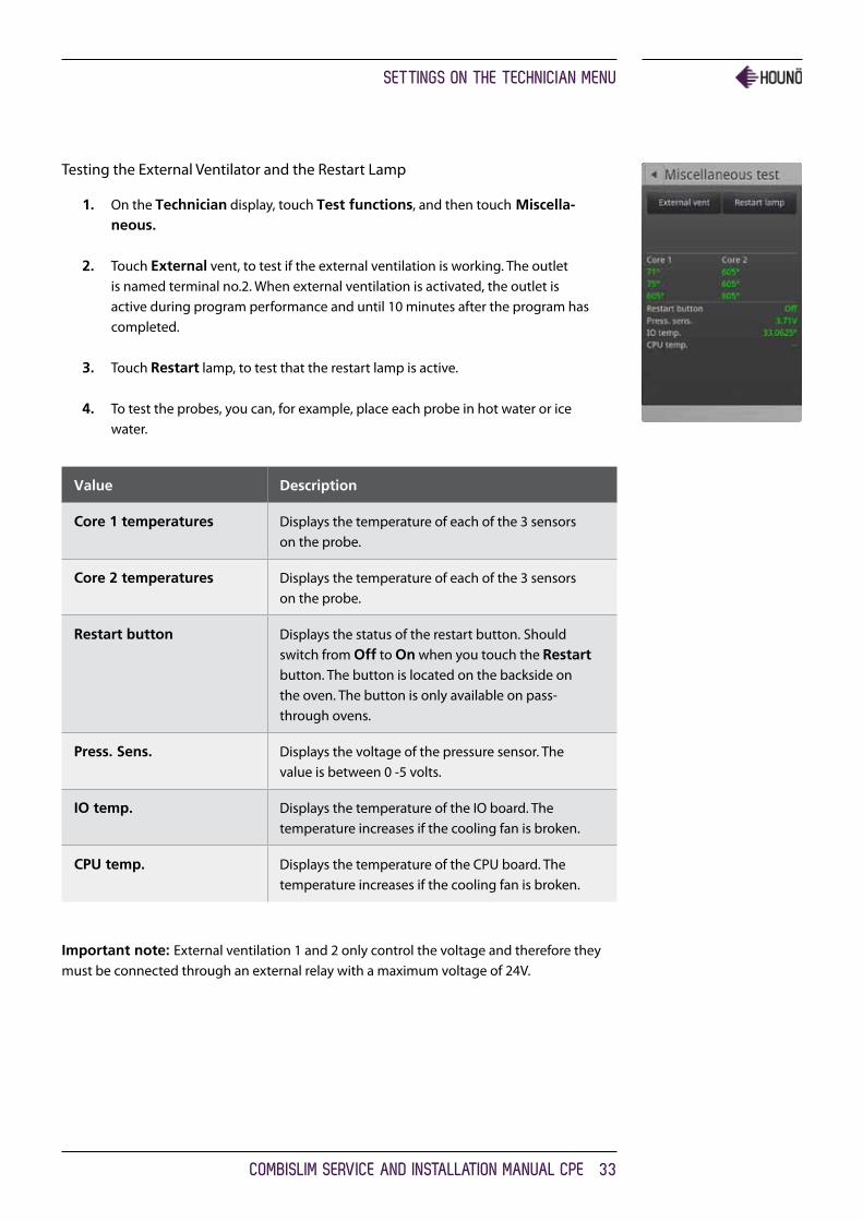
Testing the External Ventilator and the Restart Lamp
1. On the Technician display, touch Test functions, and then touch Miscella-neous.
2. Touch External vent, to test if the external ventilation is working. The outlet is named terminal no.2. When external ventilation is activated, the outlet is active during program performance and until 10 minutes after the program has completed.
3. Touch Restart lamp, to test that the restart lamp is active.
4. To test the probes, you can, for example, place each probe in hot water or ice water.
Value Description
Core 1 temperatures Displays the temperature of each of the 3 sensors on the probe.
Core 2 temperatures Displays the temperature of each of the 3 sensors on the probe.
Restart button Displays the status of the restart button. Should switch from Off to On when you touch the Restart button. The button is located on the backside on the oven. The button is only available on pass-through ovens.
Press. Sens. Displays the voltage of the pressure sensor. The value is between 0 -5 volts.
IO temp. Displays the temperature of the IO board. The temperature increases if the cooling fan is broken.
CPU temp. Displays the temperature of the CPU board. The temperature increases if the cooling fan is broken.
Important note: External ventilation 1 and 2 only control the voltage and therefore they must be connected through an external relay with a maximum voltage of 24V.

SEttINGS ON tHE tECHNICIaN MENU
34 COMbISlIM SERVICE aNd INStallatION MaNUal CPE
Testing the Alarm
This function tests the thermo-switch circuit.
5. On the Technician display, touch Test functions, and then touch Main alarm.
6. Touch Main contactor. If all status values are displayed in green and the status is On, it indicates that the alarm is working properly. If a value is displayed in red and the status is Off, a fault has occurred.
Value Description
24V Displays whether the alarm is on or off.
Fan Displays whether the alarm is on or off.
Oven Displays whether the alarm is on or off.
Generator Displays whether the alarm is on or off.
S S Relay Displays whether the alarm is on or off.

SEttINGS ON tHE tECHNICIaN MENU
COMbISlIM SERVICE aNd INStallatION MaNUal CPE 35
Making temperature adjustments
Use this function to adjust the oven or the core temperature offsets. This is useful when the temperature should correspond with the temperature of a 3rd party probe. The default setting is 0.
Adjust the Oven Temperature
1. On the Technician display, touch Adjustments.
2. Touch Oven temp offset.
3. Slide your finger up or down to select the preferred offset. You can adjust the temperature offset up or down by 10°C (50°F) in 1°C increments.
Adjust the Core Temperature
1. On the Technician display, touch Adjustments.
2. Touch Core temp offset.
3. Slide your finger up or down to select the preferred offset. You can adjust the temperature by 1-degree increments

SEttINGS ON tHE tECHNICIaN MENU
36 COMbISlIM SERVICE aNd INStallatION MaNUal CPE
Changing Oven Settings
1. On the Technician display, touch Settings. You can now change the following settings.
Setting Description
Custom mode Settings only applicable to a specific customer.
Soap level monitoring Yes/No setting.
Select Yes to display a message when the rinse or soap containers must be changed. Can only be used with standard 5 liter containers.
Drain cooling Yes/No setting.
Select Yes to automatically cool down the drain when the temperature exceeds 75°C/167°F. Cooling stops at 70°C/158°F. Note that local rules and regulations may vary.
Fan speed alarm Yes/No setting. Select Yes if you want the oven to sound an alarm when the fan speed is too slow.
Restart key Display/Both/None setting. This setting only applies to pass-through ovens.
Select Display if you only want to enable the restart button on the front display.
Select Both if you want to enable the restart button on the front display as well as the physical restart button on the rear side of the oven.
Select None, if both buttons should be disabled.
Restart time Specifies the restart time.
Restart after power failure
Yes/No restart setting.
Select Yes if you want the oven to restart after power failure. The oven restarts at the function it was in at the time of the power failure.

SEttINGS ON tHE tECHNICIaN MENU
COMbISlIM SERVICE aNd INStallatION MaNUal CPE 37
Making Corrections to bake time
Use this function to enable or disable automatic recalculation of the bake time in case of mistakes such during the baking process.
Enabling or Disabling Automatic Bake Time Corrections
1. On the Technician display, touch Bake time correction.
2. Touch BTC enabled, drag your finger up or down to enable or disable bake time corrections, and then touch OK.
Specifying Bake Time Correction Tolerance
1. On the Technician display, touch Bake time correction.
2. Touch BTC tolerance, drag your finger up or down to select the preferred value and then touch OK.
Specifying Bake Time Correction Threshold
1. On the Technician display, touch Bake time correction.
2. Touch BTC threshold, drag your finger up or down to select the preferred value and then touch OK.
Specifying Middle East Specific Settings
Enabling this setting disables all recipes containing pork.
1. On the Technician display, touch Middle East.
2. Touch Yes, and then touch OK.

SEttINGS ON tHE tECHNICIaN MENU
38 COMbISlIM SERVICE aNd INStallatION MaNUal CPE
Enabling demo mode
When you want to use the oven for demonstration purposes, you should enable demo mode. When demo mode is enabled, the heating elements and the steam generator will not be switched on when the oven is running.
1. On the Technician display, touch Demo Mode.
2. Touch Yes, and then touch OK.

tROUblESHOOtING
COMbISlIM SERVICE aNd INStallatION MaNUal CPE 39
tROUblESHOOtINGIf the oven displays an error code, try the solutions below before contacting HOUNÖ technical service.
After each step is carried out, be sure to test if the oven is working again.
General Error Codes
Error Code 4
The overheating switch of the oven chamber is off because the oven chamber temper-ature has risen above 350°C/662°F. Press the Q1 button at the rear of the oven to reset the switch.
Steps Check list Solution
1 Go to the test menu (main alarm) to see if the overheating thermo switch has tripped. Reset the switch.
2 Test whether the fan is running and whether the solid state relay is working properly.
3 Check the cable and the cable plugs.
4 - Change the overheating sensor.
5 - Change the computer.

tROUblESHOOtING
40 COMbISlIM SERVICE aNd INStallatION MaNUal CPE
Error Code 5
The fan motor is too hot (above 120°C/248°F). Let the motor cool off for about 20-30 minutes and then try turning it on again.
Steps Check list Solution
1 Go to the test menu (main alarm) to see which information is displayed.
2 Check the cable and the cable plugs.
3 Check the door sensor since 5VDC may affect the overheating circuit.
4 Check the fan motor windings. Change the fan motor.
5 - Change the computer.
Error Code 6
The drain temperature has been above 75°C/167°F for more than 5 minutes. It is normally kept below 60°C/140°F.
Steps Check list Solution
1 Check that the water is turned on.
2 Check that the water supply connected to the oven is cold and not hot.
3 Check whether the temperature sensor is broken. (Measure the real temperature and compare it to the temperature measured by the test function.)
If broken, change the sensor.
4 Clean the jet and the solenoid valve at the drain, and then check the temper-ature again.
Change the computer.

tROUblESHOOtING
COMbISlIM SERVICE aNd INStallatION MaNUal CPE 41
Error Code 7
The temperature sensor in the oven chamber is broken. The oven cannot be used until the error has been corrected.
Steps Check list Solution
1 Go to the test menu (oven) to see which temperature is displayed.
2 Check the cable and the cable plugs and change the plug if necessary.
3 Test the sensor using an ohmmeter, and check whether the value matches the value in the table and the current temperature.
If no, change the sensor.
4 - Change the computer.
Error Code 8
The probe is broken or is not connected properly. The program cannot be used until the error has been corrected.
Steps Check list Solution
1 Go to the test menu (miscellaneous) to see which information is displayed.
2 Check the cable and the cable plugs and change the plug if necessary.
3 Test the sensor using an ohmmeter, and check whether the value matches the value in the table and the current temperature.
If no, change the sensor.
4 - Change the computer.

tROUblESHOOtING
42 COMbISlIM SERVICE aNd INStallatION MaNUal CPE
Error Code 10
The temperature sensor in the drain is broken. The oven can still be used, but the error has to be corrected as soon as possible.
Steps Check list Solution
1 Go to the test menu (oven) to see which temperature is displayed.
2 Check the cable and the cable plugs and change the plug if necessary.
3 Test the sensor using an ohmmeter, and check whether the value matches the value in the table and the current temperature.
If no, change the sensor.
4 - Change the computer.
Error Code 16
The IO board temperature has risen above 60°C/140°F.
Steps Check list Solution
1 Go to the test menu to see which infor-mation the computer displays.
2 Check whether the ambient temperature is too high.
Move the oven if necessary, and clean the intake filter.
3 Check whether the test function temper-ature matches the current temperature.
Move the oven or the heat source.
5 - Change the computer.

tROUblESHOOtING
COMbISlIM SERVICE aNd INStallatION MaNUal CPE 43
Error Code 19
An internal error occurred. The oven server process is not responding. Oven server process failed.
Steps Check list Solution
1 - Restart the oven.
2 - Change the computer.
Error Code 20
An internal error occurred. A communication failure occurred between the computer and the IO board. The IO board software is not responding. Wrong software version on the IO board.
Steps Check list Solution
1 Check the wire connection between the IO board and the CPU board.
Change the IO board or the CPU board if necessary.
Error Code 21
Invalid program. The program you have chosen is not supported by the oven.
Steps Check list Solution
1 Go to the USB key function. Download the program combination that matches this oven type.

tROUblESHOOtING
44 COMbISlIM SERVICE aNd INStallatION MaNUal CPE
Error Code 22
Program interrupted. There was a power outage while the program was running. The power outage lasted for so long that the program cannot be restarted.
Steps Check list Solution
1 - The oven can be set up to restart after a power outage. Contact service personnel.
Error Code 28
An invalid combination of the mains alarm has been detected. The mains alarm is not displayed correctly.
Steps Check list Solution
1 Go to the test menu to see which infor-mation the computer displays.
2 Check the cable and the cable plugs. Change the plug if necessary, and then test if the alarm is working.
3 - Change the sensor.
Error Code 29
The door sensor is not working properly. Note the oven does not stop working when the door is opened. The oven can be used.
Steps Check list Solution
1 Go to the test menu to see which infor-mation the computer displays.
2 Check the cable and the cable plugs, and the test if the sensor is working.
3 Check the magnet on the drip slide. Change the drip slide.
4 - If the magnet works, change the door sensor, and remember to calibrate the door afterwards.

tROUblESHOOtING
COMbISlIM SERVICE aNd INStallatION MaNUal CPE 45
Error Code 34
The water pressure is too low.
Steps Check list Solution
1 Check that the water is turned on. Clean the solenoid valve filter.
2 Check that the water pressure is at least 2.5 bars.
Change the sensor.
Error Code 37
While running the CombiWash program, the oven could not cool down to set point.
Steps Check list Solution
1 Check that the jet in the oven chamber is working.
Run CombiWash step 0 before using the oven.
Error Code 38
CombiWash was interrupted while there was still detergent in the oven chamber.
Steps Check list Solution
1 - Run CombiWash step 0 before using the oven.
Error Code 39
There is insufficient memory to run the selected operation.
Steps Check list Solution
1 - If possible, delete some HACCP files.

tROUblESHOOtING
46 COMbISlIM SERVICE aNd INStallatION MaNUal CPE
Error Code 40
The IO board temperature has been too high.
Steps Check list Solution
1 - Clean the filter at the bottom of the panel. Note that this is a warning. If the temperature continues to rise, the oven will stop and display error code 16.
Error Code 45
There is no 24VAC. Main contactor output is not working.
Steps Check list Solution
1 Check fuse F1.

SafEty
COMbISlIM SERVICE aNd INStallatION MaNUal CPE 47
SafEtyPlease read the safety instructions carefully.
• Ensure that installation is carried out by qualified installation and service personnel only.
• Read, understand, and follow the instructions for use.
• Place trays filled with hot liquid at the bottom runners of the oven chamber and practice extreme caution when removing the tray from the oven chamber.
• Do not store petrol or other flammable vapors or liquids in the vicinity of this appliance.
• Do not touch hot surfaces. The temperature of some surfaces may exceed 60°C/140°F or more.
• Do not attempt to operate or open the oven during the automatic cleansing process.
• Use the parking brakes on the trolley wheels to prevent trolleys from rolling on uneven floors.
• Contact qualified service personnel before you make changes to the set-up of the oven. Incorrect changes may have serious effects on its reliability in service.
SERVICE aNd REPaIR
48 COMbISlIM SERVICE aNd INStallatION MaNUal CPE
SERVICE aNd REPaIR • All maintenance and repair must be carried out by qualified installation and service
personnel only. Installation or service by other than qualified personnel may result in damage to the oven and/or injury to the operator.
• When cleaning the oven, only use cleaning detergent that matches the specifica-tions from the factory. Do not use corrosive cleaners not intended for oven cleaning on you CombiSlim oven.

WaRRaNty
COMbISlIM SERVICE aNd INStallatION MaNUal CPE 49
WaRRaNty If you have registered your CombiSlim oven on our website, it is covered by a 48-month factory warranty. The warranty covers the oven cabinet and spare parts. There is a special 10-year warranty on the exterior door glass. The warranty takes effect from the date of production.
To view the full terms of the warranty and to register, go to http://www.houno.com/warranty/.
Excluded from Warranty
Excluded from the warranty are certain damages including but not limited to the following:
• Glass parts such as interior door glass, lamp glass or halogen lamps
• Sealings
• Damage or malfunction resulting from installation that is not in accordance with HOUNÖ instructions and specifications for the product.
• Damage resulting from accidents, including damage caused by water, transport, misapplication or negligence.
• Malfunction and interruptions of operation that are the result of the oven not being operate in accordance with HOUNÖ instructions and specifications on how to use the product.
HOUNÖ cannot be made liable for indirect loss, including loss of profits.

GEt IN tOUCH.As your combi oven specialist,
we always do our utmost
to help our customers.
Worldwide.
HOUNÖ a/SalSVEj 1dk-8940 RaNdERS SVdENMaRk
t: +45 8711 4711E: [email protected]
www.houno.com
PaRt Of