comision nacional de actividades espaciales facultad de...
TRANSCRIPT

Comision Nacional de Actividades Espaciales(CONAE)
Facultad de Matematica Agronomia y Fisica(Fa.M.A.F)
Spacecraft Systems Design
Master in Space Applications for Emergency Early Warning andResponse
Author: Gonzalo Sebastian PeraltaProfessor: Dr. Marcelo Scavuzzo
Cordoba, Argentinafinal report: August 2010

2

Contents
Abstract i
1 Introduction 11.1 Background . . . . . . . . . . . . . . . . . . . . . . . . . . . . . . 11.2 Payloands and Missions . . . . . . . . . . . . . . . . . . . . . . . 11.3 Spacecraft Systems . . . . . . . . . . . . . . . . . . . . . . . . . . 21.4 Document Scope . . . . . . . . . . . . . . . . . . . . . . . . . . . 21.5 Project work objectives . . . . . . . . . . . . . . . . . . . . . . . 3
1.5.1 General objective . . . . . . . . . . . . . . . . . . . . . . . 3
2 Ground System 52.1 Components . . . . . . . . . . . . . . . . . . . . . . . . . . . . . . 5
2.1.1 Facilities . . . . . . . . . . . . . . . . . . . . . . . . . . . . 52.1.2 Control Centers . . . . . . . . . . . . . . . . . . . . . . . . 5
2.2 Hardware . . . . . . . . . . . . . . . . . . . . . . . . . . . . . . . 72.2.1 Antenna System . . . . . . . . . . . . . . . . . . . . . . . 82.2.2 Receive RF equipment . . . . . . . . . . . . . . . . . . . . 82.2.3 Transmit RF equipment . . . . . . . . . . . . . . . . . . . 82.2.4 RF communications link . . . . . . . . . . . . . . . . . . . 92.2.5 Mission Data Recovery Equipment . . . . . . . . . . . . . 92.2.6 Data User Interface . . . . . . . . . . . . . . . . . . . . . 92.2.7 Station Contol Center . . . . . . . . . . . . . . . . . . . . 9
2.3 Software . . . . . . . . . . . . . . . . . . . . . . . . . . . . . . . . 92.3.1 Pre-pass . . . . . . . . . . . . . . . . . . . . . . . . . . . . 92.3.2 Real-time . . . . . . . . . . . . . . . . . . . . . . . . . . . 102.3.3 Post-pass . . . . . . . . . . . . . . . . . . . . . . . . . . . 102.3.4 On-board Software . . . . . . . . . . . . . . . . . . . . . . 10
2.4 Monitor and Control . . . . . . . . . . . . . . . . . . . . . . . . . 102.5 Design . . . . . . . . . . . . . . . . . . . . . . . . . . . . . . . . . 11
2.5.1 Ground Station Locations . . . . . . . . . . . . . . . . . . 112.5.2 Requirements for Data Handling . . . . . . . . . . . . . . 122.5.3 Communication Links . . . . . . . . . . . . . . . . . . . . 132.5.4 Link Data . . . . . . . . . . . . . . . . . . . . . . . . . . . 13
2.6 AFSCN: An Example of not dedicated system design . . . . . . . 142.6.1 AFSCN clients . . . . . . . . . . . . . . . . . . . . . . . . 14
2.7 CONAE: An Example of dedicated system design . . . . . . . . . 152.7.1 CGS Design Concept . . . . . . . . . . . . . . . . . . . . . 15
3

4 CONTENTS
3 Spacecraft Computer Systems Design 173.1 Requirements Definition . . . . . . . . . . . . . . . . . . . . . . . 173.2 Architecture . . . . . . . . . . . . . . . . . . . . . . . . . . . . . . 19
3.2.1 Data Architecture . . . . . . . . . . . . . . . . . . . . . . 193.3 Trade-off in Computer System Requirements . . . . . . . . . . . 20
3.3.1 Programming Language . . . . . . . . . . . . . . . . . . . 223.3.2 Tolerating Faults . . . . . . . . . . . . . . . . . . . . . . . 23
3.4 Software for Processing Tasks . . . . . . . . . . . . . . . . . . . . 233.5 Software Size and Throughput . . . . . . . . . . . . . . . . . . . 243.6 Computer Selection . . . . . . . . . . . . . . . . . . . . . . . . . . 243.7 Integration and Test . . . . . . . . . . . . . . . . . . . . . . . . . 253.8 Life-Cycle Support and Standads . . . . . . . . . . . . . . . . . . 25
4 Documentation and Interfaces 274.1 Documentation . . . . . . . . . . . . . . . . . . . . . . . . . . . . 27
4.1.1 ESA software engieeniering . . . . . . . . . . . . . . . . . 284.2 Interfaces . . . . . . . . . . . . . . . . . . . . . . . . . . . . . . . 30
5 Conclusion 33
A Appendix 35A.1 TacSat-2 . . . . . . . . . . . . . . . . . . . . . . . . . . . . . . . . 35

Abstract
In the development of a space system it is necessary a correct design to achievean overall optimum in which the mission objectives are realized efficiently ap-plying system engineering. In a space system, there must be in addition to thefly system, a supporting ground control system (ground segment) that enablescommands to be sent up to the vehicle (fly segment) and that allows to returnto the ground status and payload information. It is important, also, to takeinto account the interaction between the differents elements that are part of thewhole space system, these interactions are made by the interfaces which havethe task of assurance the correct communication between space system com-ponents. How to the engineering should be applied on the design of a spacesystem, (including the fly segment, the ground segment and the interfaces) isthe main goal covered in this paper.
i

ii ABSTRACT

Chapter 1
Introduction
1.1 Background
Man has only had the ability to operate spacecraft successfully since 1957, whenthe Russian Sputnik I, was launched into orbit. In more than five decades,unmanned explorer spacecraft have flown past all the major bodies of the solarsystem except for Pluto. Vehicles have landed on the Moon, Venus and Mars,and the Galileo spacecraft probe ’landed’ on the gaseous ’surface’ of Jupiter in1995. Current space activity seems to be ongoing to the International SpaceStation [23](ISS, construction of the station began in 1998 and is scheduledfor completion by late 2011), and this represents a major step for both thetechnology and the politics of the space industry. The United States, Europe.Russia and Japan are involved in this ambitious, long-term program[13] and isby far the largest artificial satellite that has ever orbited Earth. [?] Technologicaladvances in space in many areas have been achieved. Particularly notable thedevelopments in energy-conversion technologies, fuel cells and batteries. But themost important developments in this period have been in electronic computerand software, helping to the growing in space technologies.
1.2 Payloands and Missions
Payloads and missions for spacecraft are many and varied (Figure 1.1 shows thedifferent types of payload/mission existing), such as satellites for communica-tions, weather and navigation purposes. Others monitor Earth for its resources(Landsat, SAC-C, SAC-D), the health of its crops and pollution (MODIS). De-termination of the extent and nature of global warming is only possible usingthe global perspective provided by satellites (may be TERRA and AQUA areconcrete examples), and the monitoring of ozone holes over both poles is ofgreat importance to mankind. Other satellites serve the scientific communityadding to Man’s knowledge of the Earth’s environment, the solar system andthe universe. Each of these peaceful applications is paralleled by inevitable mil-itary ones. By means of global observations, acquired knowledge of militaryactivities on the surface of the planet and the deployment of aircraft. Commu-nication satellites serve the military user, as do weather satellites. The GlobalPositioning System (GPS) navigational satellite constellation is able to provide
1

2 CHAPTER 1. INTRODUCTION
Figure 1.1: payload/mission types [13]
an infantry man, sailor or fighter pilot with his location to an accuracy of abouta meter [13].
1.3 Spacecraft Systems
When considering spacecraft, it is convenient to subdivide them into functionalelements or subsystems. But also we have to take into account that theremust be a supporting ground control system that enables commands to be sentup to the vehicle and status and payload information to be returned to theground (Figure 1.2 shows the total system schema [13]). Each of the elementsof the overall system must interact with the other elements (interfaces), and itis the job of the system designer to achieve an overall optimum in which themission objectives are realized efficiently. Then the system will comprise all theelements within both the space and the ground segment of a spacecraft project,including the interfaces[19]. One facet of these subsystems is that the design ofany one has impacts and resource implications on the others. The varied missionrequirements, coupled with the need to minimize mass and hence power, has thusled to a wide variety of individual design solutions being realized. However, thespacecraft industry is now evolving towards greater standardization. [13][26].
1.4 Document Scope
The framework of this document is the subject “Seminario” in the context ofthe “Maestrıa en Aplicaciones Espaciales de Alerta y Respuesta Temprana aEmergencias, Comision Nacional de Actividades Espaciales (CONAE)”. Howthe space system engineering should be applied to the development of a spacesystem, including the fly segment, the ground segment and the interfaces, givingto the reader some examples for a better understanding is the main topic coveredin the present work.

1.5. PROJECT WORK OBJECTIVES 3
Figure 1.2: The total system schema: space and ground segment
1.5 Project work objectives
1.5.1 General objective
To make a revision of several papers related to the design of space systems,including both, the fly segment and the ground segment.

4 CHAPTER 1. INTRODUCTION
Chapter 2
Ground System
Ground Systems acquire mission data from a spacecraft and its instrumentsand transfer it to the data users. They also supplies telemetry and trackinginformation that users may need. Most space missions allow the user’s evolvingrequirements to influence changes in the ground system’s data relay and con-trol functions. Ground systems consist of ground stations and control centersworking together to support the spacecraft and the data user. In this chapter,I will present the key concepts that are necessary to take into consideration atdesign time of a Ground System. I will introduce the components of a GroundSystem and its relationships. Finally I will introduce two examples of GroundSystems existing today.
2.1 Components
The ground system consists of mission elements and facility elements (Figure2.1). Mission elements control the space segment or handle mission data. Fa-cility elements are ancillary to mission elements. Both contain mixes of varioushardware, firmware, and software. The ground system staff uses and coordinatesthe operation of the physical components. Mission operations, coordinates ac-tivities for the ground system and command and control of the spacecraft. Theground station (where the ground system is) is the Earth-based point of com-munication with the space segment (spacecraft) for control and, typically, userdata. Next section presents the basic ground station components [14].
2.1.1 Facilities
Plan facilities include buildings and grounds, utilities, services for the staff,and security. Normally it would use commercial utilities with locally generatedbackup for emergencies. For security and survivability, utilities may be whollyself-contained. Because plants are expensive, it must decide whether to buildunique dedicated systems or to use existing alternative systems [19].
2.1.2 Control Centers
Three types of control centers are generally found within ground systems. TheSpacecraft Operation Control Center (SOCC) monitors and command the space-
5

6 CHAPTER 2. GROUND SYSTEM
Figure 2.1: Mission and Facility Elements for a Ground System.
craft bus and common systems. Also analyzes spacecraft telemetry and missiondata from instruments which can affect the spacecraft’s attitude and dynamics.It coordinates and controls POCC access. For simple spacecraft, the SOCCalso serves as the POCC. On the other hand, we may need several SOCCs ifthe space segment is complex.
The Payload Operations Control Center (POCC) analyzes telemetry andmission data from on-board payload instruments and issues commands to theseinstruments. Its commands depend on approval by the mission control center,with coordination from the SOCC. Interactive computer equipment also runsthe POCC. We may use multiple POCCs when several on-board instrumentsneed full-independent supervision or when we need a backup for redundancy.
The Mission Control Center (MCC) plans and operates the entire spacemission, including the configuration and scheduling of resources for both spaceand ground system. It computes and issues information needed by groundsystem elements and data users, such as data on the spacecraft’s orbit, groundstation pass times, and antenna pointing angles. In simpler systems, we maymerge the MCC with the SOCC.
Figure 2.2 shows how the segments interact generally, the ground systemcommands and controls the spacecraft based on requests from the data userto the control centers. Except for communications satellites, user do not sendcommands independently to the spacecraft. The ground system tries to providehighly available, high-fidelity access to the spacecraft while remaining transpar-ent to both data users and ground controllers. In practice though, we musttrade off transparency and cost.
From here to the rest of this chapter are summarized the main functionsperformed at ground station in support of an operational spacecraft. Thesefunctions, usually involving the followings tasks:
• Tracking to determine the position of the satellite in orbit;

2.2. HARDWARE 7
Figure 2.2: Relations between Data Users, Ground System, and Space Segment
• Telemetry operations to acquire and record satellite data and status.
• Commanding operations to interrogate and control the functions of thesatellite.
• Controlling operations to determinate orbital parameters, to schedule allsatellite passes and to monitor and load the on-board computer.
• Data processing operations to present all the engineering and scientificdata in the correct format.
• Voice and data link to other worldwide ground stations and processingcenters.
2.2 Hardware
The main hardware components of a ground station are: an antenna, a receive-transmit system, data recorder(s), computer(s) and their peripherals and controlconsoles. This is a basic list that does not significantly change with the type ofspacecraft being controlled, and applies equally to Space Science, Earth Obser-vation/Remote Sensing and to Telecommunications. Although the antenna isthe main item of hardware at a ground station, the other items are an impor-tant part of its facilities. To support spacecraft and their payload, the groundsystem must command and controls them, monitor their health, track them todetermine orbital position, and determine spacecraft attitude from sensor infor-mation, although some of these functions are currently carried out on-board thespacecraft. The ground system controls the spacecraft and its instruments orpayloads by transmitting command data to carry out these functions. It acquiresmission data from a spacecraft and its instruments and transfers it to the datausers. The ground system also supplies any telemetry and tracking informationthat they may need. Figure 2.3 shows the basic ground station components, it

8 CHAPTER 2. GROUND SYSTEM
Figure 2.3: Figure extracted from [14]: The basic ground station components.
has only the minimum components needed to control a spacecraft and to relaymission data to users [14] [19].
2.2.1 Antenna System
It includes the antenna and mount, its associated electromechanical actuators,the consoles and servo circuitry that control the antenna and the feeds andtransmission lines that carry RF signals to and from the RF equipment. Thesupport functions of an Antenna may include tracking, telemetry, command,space-ground voice and television capabilities. The antenna has several fre-quencies possible to operate: S-band system, the K-band system, the L-bandsystem and the X-band system. The antenna must also provide the look an-gles required by the mission. For low-Earth orbit missions, these can coveressentially all the visible hemisphere. It must also provide the required steeringmodes, such as programmed computer steering and autotracking. Autotrackingrefers to the use of the received spacecraft signal itself to steer the antenna. Inthis case, the antenna system usually provides continuous pointing coordinatesto the tracking component at the ground station.
2.2.2 Receive RF equipment
It is generally in suites of racks, located to minimize transmission-line losses tothe antenna. This equipment accepts the down-link carrier frequency from theantenna system, down-converts it to intermediate frequencies and demodulatesit to baseband signals for the equipment devoted to Mission Data Recoveryand TT&C (Telemetry Tracking Command).
2.2.3 Transmit RF equipment
Also in racks near the antenna system, accepts tracking and command signalsfrom the ground system’s TT&C component and modulates and generatesthem onto the RF up-link. In the case of communication satellites, it alsomodulates user data onto an up-link carrier.

2.3. SOFTWARE 9
2.2.4 RF communications link
It is in charge of spacecraft/payload control, sending commands, determinationof orbital parameters, monitoring and processing of telemetry, determination ofspacecraft attitude, transmission of spacecraft and payload data and missionoperations support. Generally, the ground system commands and controls thespacecraft based on requests from the data user to the control centers. Exceptfor communications satellites, users do not usually send commands indepen-dently to the spacecraft.
2.2.5 Mission Data Recovery Equipment
It conditions the mission data before relaying it to data users and ground systemcomponents. It typically has its own location in the system. but it may beintermingled with the receive RF suite for simple data streams.
2.2.6 Data User Interface
It connects the Mission Data Recovery equipment and the Data User. TheTT&C equipment conditions and disributes received telemetry and trackingsignals. It also electrically formats, authenticates and times transmitted com-mand and tracking signals. It usually processes these tracking signals and dataon the antennapointing angle to inform users about range, range-rate and space-craft position. TT&C functions are usully highly automated because of needfor speed, timeliness and accuracy.
2.2.7 Station Contol Center
It controls the configurations and the interconnects between the ground sta-tion components. It keeps the ground station configured to support missionoperations.
2.3 Software
There are four major areas of software that either run at or are controlled froma ground station. These are the pre-pass, real-time, post-pass and on-boardsoftware. Except for the most basic spacecraft systems, some aspects of each ofthese will be required in the ground station. In addition, there are a numberof very important configuration control procedures that need to be adopted tosafeguard the integrity of the software part of the ground system.
2.3.1 Pre-pass
It is the software required to run in advance of the pass of an active spacecraftover ground station. There are four types of software required:
• Orbit Determination and Prediction: consist on determining andpredicting the orbit of satellite.

10 CHAPTER 2. GROUND SYSTEM
• Observation Planning and Scheduling: the observatin planning andscheduling software will include all requests from the spacecraft user. Itchecks that observation modes, attitude control or spacecraft constraintsare not violated. It will then schedule all observations into an optimizedorder.
• Command List Generation: A pass schedule is constructed as far of thepass as possible. It contains a set of Orbit determination and predictioninstructions or commands that define the actions to be taken during thepass, the tracking data, the new satellite plan and any other data to beloaded into the computer memory.
• Simulation: This is used post-launch to aid problem-solving in the eventof partial spacecraft or subsystem failure. For exactly the same reasons, itis prudent to provide well in advance of launch a simulator for the completeend-to-end ground system. This includes the capability to simulate boththe spacecraft housekeeping data as well as the instrument data. It is alsouseful for training operation staff and checking the satisfactory handlingof corrupted data.
2.3.2 Real-time
Real-time software operates during the whole of the period when the spacecraftis visible from the associated ground station. It includes computer control of theantenna tracking, command up-link and verification, data reception and statuschecking of all critical system parameters.
2.3.3 Post-pass
It includes extraction of housekeeping and science/technology data for qualitycontrol and health assessment, data processing, orbit determination and dataanalysis.
2.3.4 On-board Software
This software resides in the spacecraft’s on-board computer; there are two ba-sic types. Read-Only Memory (ROM) contains the basic instructions and safe-guard modes during operations, and is built into the spacecraft computer beforelaunch; once launched, it cannot be changed (The initial process could be storedhere). Random Access Memory (RAM) software contains more subtle instruc-tions for the spacecraft, giving it a greater deal of sophistication and flexibility.It can be programmed before launch, but has the added advantage that it canbe modified or built up after launch by up-linking from the ground station.
2.4 Monitor and Control
Controlling the design, development, integration, testing and modification of alarge software system is a complicated task in any business. Software should bedeveloped according to a standard software life cycle (i.e. requirements, design,development, test, integration and documentation) [?]. Throughout the design,

2.5. DESIGN 11
build, integration and test period it is necessary to keep a strict control onchanges to the design of software.[16]
2.5 Design
Because more complex ground systems are less transparent, they must be de-signed as simply as possible, consistent with mission requirements. In the designof a space mission, it should be traded off space segment and ground systemcomplexity through several iterations, until we produce best performance atlowest cost.[25]
This process is iterative because the steps are interrelated and we must strikea balance in complexity between the spacecraft and the ground system. In thisway each iteration must address:
• Ground station locations.
• Requirements for data handling.
• Link data rates.
• Appropriate communications between ground system elements and datausers for a dedicated system.
2.5.1 Ground Station Locations
Figure 2.4 shows the physical layout of a simple ground system with its datausers collocated, eliminating the need for long-distance communications linkbetween them. Such a system can provide low-coverage support. One of its ad-vantages is that it can be dedicates to a particular mission, thereby eliminatingschedule conflicts. Also it is compact and self contained, allowing all communi-cations between elements to be local and dedicates thus simplifying the system’soperation and administration. As disadvantages the single ground station pro-vides very low coverage for low-Earth orbit spacecraft because a pass lasts onlyfew minutes, and for the other than near-equatorial orbits, does not occur often.The maximum viewing angle of a low-Earth orbit spacecraft from any point onthe Earth is 20% or less of the orbital path, and for inclinations above 25 or30 deg, only 25% to 30% of the orbits are visible. An exception is polar orbitsas seen from polar grounds stations where each orbit is visible. Another limitis the system cannot support more than one spacecraft link at a time becauseof the single antenna and ground station and the simple system can serve onlyon-site users. The system’s most important disadvantage, however, is its lackof redundancy. If any element were to fail we would lose data, or possibly evena spacecraft. Thus, redundant equipment, spares, and maintenance, as well asgeographical location, are particularly important. For this reason, the militarywould generally not want a simple or basic system [19].
On the other hand to support realistic space mission, a ground system mustprovide high coverage simultaneously for several spacecraft in various orbits,with high levels of availability, security and survivability (militar missions). Anexample of such kind of system is shown in the Figure 2.5 It includes standardstations and less capable auxiliary stations, these fill gaps in coverage, using

12 CHAPTER 2. GROUND SYSTEM
Figure 2.4: A Typical Installation for Basic Ground System.
equipment similar of regular stations and providing radar tracking, telemetry,data reception, and backup command.
Here it can be employed multiple control centers in separate locations, somePOCCs are near the SOCC, whereas some are remote. The SOCC is designedas prime, colocate it with a prime MCC, and back up both prime centers withremote centers. Multiple contol centers are redundant, suvivable, and flexible,allowing responsibility for prime control to pass back and forth between thecenters during various phases of the mission. Geographical dispersion and mul-tiplicity of elements complicate a ground system’s design. Each location mustusually have its own synchronized timing system, and it is needed several phys-ical plants with different administrative structures, complicated maintenanceand logistics networks, and reliable communications links.
2.5.2 Requirements for Data Handling
Data user demands usually make ground systems more complex. The user inter-face must have versatile switching and interconnection options and connect tolong-distance communications links. We may need to add data-handling equip-ment to distribute received data to different users. Data handling includes allprocessing of mission data between the ground station’s data recovery equipmentand the data user’s communications interface. For example, TCP (TransmissionControl Protocol) provides a degree of assured data delivery, but adds overheadto the data transfer. UDP (User Datagram Protocol) uses less overhead butprovides no assurance of delivery of any packet of data. Another example ofdesign considerations is the data security. Classified or secure data from space-craft is often encrypted on board before transmitting it to the ground whereit is decrypted. Some data may be re-encrypted before transmission to someusers, in order to prevent unauthorized commanding by others, command datais often encrypted as well. We may apply encoding (a technique which decreaseserrors in digital data) or not. We may apply data compression, that means to

2.5. DESIGN 13
Figure 2.5: Realistic Space Mission Ground System.
increase in the information capacity. We may apply time tagging, that meansadding timing information to data streams. And so on we can to considerate alot of things about Data Handling that will do or not more complex our DataHandling schema.
2.5.3 Communication Links
Ground systems need long-distance communications links of sufficient band-width between their distributed elements and between them and the data users.These links mix landlines (electrical, terrestrial microwave, and optical) andsatellite connections. Unless the links are part of the ground system itself, theyare usually subscribed to. We have to evaluate communications options whiledetermining where to locate the ground system’s components. For example, wemay want to place the SOCC or the MCC near a metropolitan area to takeadvantage of its telephone system, but we would want to place ground stationsin less populated areas to lessen radio-frequency interference. Yet installing newand dedicated communication facilities in a remote area may be quite costly.Now it is common to use satellites to provide communications between remoteground system elements and data users, because of their high capacity andperformance.
2.5.4 Link Data
The stations may need several antennas to support more than one RF linkor spacecraft at a time. The antennas may have multiple feeds to support

14 CHAPTER 2. GROUND SYSTEM
simultaneous links at different RF frequencies, or polarization diversity to sup-port simultaneous multiple links at the same frequency. Multiple RF links inturn require more RF and data recovery equipment, with enhanced performanceneeded to allow higher data rates and more sophisticated modulation techniques.Improved TT&C equipment increase rates for telemetry and command, moreprecise tracking, and increade coverage for several spacecraft at one time.
2.6 AFSCN: An Example of not dedicated sys-tem design
Instead of building a dedicated system, we can use existing ground support net-works to supply part or all of the elements needed. A number of commercial andmilitary ground systems can handle more than one mission and are available tosupport user missions. In this service-provided arrangement, the host systemsprovides most of the elements of the ground system. These existing configura-tions cannot satisfy all possible missions, so host systems are usually tailoredto particular kinds. Where necessary, a user mission may have to provide somespecial equipment, but they can reduce the amount by designing missions tomatch the host’s configuration wherever possible. In fact, users must usuallymeet severe constraints to make their missions compatible with the host systemand other user missions. As an example of a service-provided ground systemI present the Air Force Satellite Control Network (AFSCN) a ground systemoperated by the United State Air Force [17]. The AFSCN is a common user,satellite control network that supports the Department of Defense (DoD), theIntelligence Community (IC), National Aeronautics and Space Administration(NASA) and National Oceanic and Atmospheric Administration (NOAA) pro-grams. The AFSCN is a common user, unclassified network where all users sharethe network within a disciplined network schedule. The AFSCN is composedof three segments: range, communications and network management. It has8 ground stations, called Automated Remote Tracking Stations (RTS), locatedthroughout the world. Six of these are dual stations, able to support 2 spacecraftsimultaneously. These stations communicate with 2 central facilities or nodes,called the Consolidate Space Test Center (CSTC) in Sunnyvale, California, andthe Consolidated Space Operations Center (CSOC) at Falcon Air Force Base,Colorado, through an array of ground links and communications satellites, in-cluding DSCS, GE, and Intelsat. Each user mission’s SOCC, POCC, and MCCare generally combined into a single MCC, at one of the central nodes, withfacilities including computers and software for both operations and planning.Figure 2.6 shows the AFSCN resources long for the world.
2.6.1 AFSCN clients
The current users of AFSCN are the Department of Defense (DoD), the In-telligence Community (IC), National Aeronautics and Space Administration(NASA) and National Oceanic and Atmospheric Administration (NOAA) pro-grams. The AFSCN is capable of providing worldwide support to OperationalResponsive Space (ORS) missions. The AFSCN has already supported, for ex-

2.7. CONAE: AN EXAMPLE OF DEDICATED SYSTEM DESIGN 15
Figure 2.6: AFSCN Resources
ample, the ORS TacSat-2 1 experiment and is currently planning to supportfuture missions to include TacSat-1A, TacSat-3, TacSat-4 and others as appro-priate.
2.7 CONAE: An Example of dedicated systemdesign
In this section, I present a summary of the architectural design concept of:CONAE Ground Segment (CGS) [24]. CONAE Ground Stations Service (CGSS),in charge of the execution of the plan and all Monitor and Control (M&C) ac-tivities of the Ground Station Operations Center (GSOC). Three antennas aremanaged by the CGS; one X-Band down link, S-Band up-down link of 13 meters;one X-Band down link of 7,3 meters; and one S-Band up-down link of 4 meters.The CGS particulary the CGSS, downloads data from several satellites (AQUA,Landsat 5 and 7, Terra, EROS, etc.) and operates as the main station for theSAC-C Argentine mission, both for TT&C and science data downloading.
2.7.1 CGS Design Concept
Figure 2.7 shows the top level design concept of the CGS. In the figure, the whiteboxes represent CONAE’s components. The Grey boxes represent all foreigncomponents. The purpose of this functional diagram is to present the mainfunctional components of CGS and those of CONAE’s foreign partners. Thecomponent located over the white background are located on CONAE facilities.The box representing the flight segment is depicted in both colors due to thetypical cooperative ownership of this segment.
1TacSat-2 is a small satellite for developing low-cost, customized and rapidly deployablespace capabilities for war-fighters. See Apendix A

16 CHAPTER 2. GROUND SYSTEM
Figure 2.7: Figure extracted from [24]: CONAE Ground Station
The CONAE Ground Station Service (CGSS)
It groups all CONAE ground stations both for TT&C (S-Band) and for sciencedata downloading (X-Band). Basically it consists of all CONAE’ antennas, theRF equipment, Data Acquisition equipment, and the M&C system.
The CONAE User Ground Segment Service (CUGSS)
They are the services for both Argentine and foreign users interested in prod-ucts generated by CONAE, independently of being they products from its owninstruments or not.
The CONAE Telemetry (TM) and Telecommand (TC) ProcessingNode Extendions (CTCPNE)
It allows CONAE to receive TM and to send TC in a foreign location from andto CONAE’s missions.
The CONAE Data Acquisition Extensions (CDAE)
It allows a foreign partner to acquire some of CONAE’s instruments data at aforeign location using the FGSS (Foreign Ground Segment System).
The CONAE User Ground Segment Extensions (CUGSE)
It allows a foreign partner to generate some of CONAE’s instruments.
The CODS
It incudes orbit determinations, orbit propagation, two line elements generationand distribution, ground station contacts generation, computation, etc.

Chapter 3
Spacecraft ComputerSystems Design
As I have shown before, mission-supporting computer systems include the com-puters onboard the spacecraft, as well as those on the ground. Figure 3.1 showsthe fly segment and the ground segment with some subsystems. The subsystemspresent in the fly segment (space) include the spacecraft computer control Sys-tem, the payload sensor computer, and the fly segment data architecture whichis a bus data in this case. Regarding to the subsystems present in the groundsegment, an interactive user interface, and some mission elements (2.1) can beseen also in the figure 3.1. Previous chapters were addressed by ground segmentdesign and configurations. This chapter will address the design on board tothe spacecraft. On board the spacecraft, computers have become an integralpart of the overall system. The process of develop a computer system onboardspacecraft is, as in ground system design, an iterative process and it is based onthe mission requirements. It is pursuited the availability, capability, flexibility,and reliability of the system by minimizing cost and risk. The objective is tomeet the system and mission requirements, whether the resulting system is onthe ground, in space, or distributed between the two. As mission objectivesexpand, we must combine complex hardware and software to meet them. Anincrease in system complexity leads to an exponential increase in the associatedtesting. To keep the computer systems simple at the lowest level is as impor-tan as building up the capabilities to meet the top-level mission requirements.Computer systems consist of hardware, software, and their interface definitionsand documentation. Hardware and software components are in a hierarchy,building to the final configuration item. Documentation also has a hierarchy,but it starts with top-level requirements and are increased while it is improvethe implementation detail. (Figure 3.2).
3.1 Requirements Definition
As with all subsystems, poor computer system requirements definition resultsin an inferior product; erroneous requirements are very expensive to correct.Defining system requirements is difficult, subjective, and time consuming [1][18]. Figure 3.3 is an example of a simple state diagram for a computer system.
17

18 CHAPTER 3. SPACECRAFT COMPUTER SYSTEMS DESIGN
Figure 3.1: Mission Computer System
Figure 3.2: Hierarchy of Elements In a Computer System.

3.2. ARCHITECTURE 19
Figure 3.3: Typical State Transition Diagram for an Onboard Computer System
For a specific mission and mission requirements we might have several substatesin place of one state. Or we might not have a state shown in the figure, if itis not applicable to our mission[20]. User requirements are all the requirementsfrom the user point of view, while the software requirements are requirementsmore detailed and they used to be specified in a more technical way. The ESAspecifies standars and suggestions for both, the user requirement specificationand software requirement specification practices in [10] and [8].
3.2 Architecture
The architecture shows us the system’s parts and how they interact througha block diagram. Architecture studies for computer systems must address thetop-level block diagram, the data architecture, the hardware architecture, andthe software architecture. Data architecture addresses the physical structure ofthe data network or bus, as well as the protocol1 or logical interaction across thebus. The hardware architecture defines the instruction set architecture (ISA)and the functional elements that are available in hardware. Finally, the softwarearchitecture defines how the processing instructions are executed. Softwareprocessing can be processed as a single thread, executing from top to bottom,repetitively, or as scheduled modules, where processing order is based on majorand minor frames. Alternatively, software processing can be event driven, whereinterrupt service routines preempt normal execution in a deterministic way whenhardware interrupts occur[12].
3.2.1 Data Architecture
There are several kind of data architecture. Figure 3.4 shows a centralized ar-chitecture often called star. This data architecture has Pros and Cons. Thiskind of architecture works best with a few, well-defined systems which all mod-ules interface directly, and only, with the central computer. And it is highly
1A protocol is a set of rules for sending data between computers, or between computersand peripherals. It is the communication language between two computers.

20 CHAPTER 3. SPACECRAFT COMPUTER SYSTEMS DESIGN
Figure 3.4: Star architecture
reliable architecture, where failures along one interface will not affect the othersinterfaces. As Cons, adding a new node requires both hardware and softwarechanges in the central node. And wiring become large because each node hasduplicate transmission wires if data are sent to multiple receivers.
Figure 3.5 presents a distributed ring architecture. This establishes a way toarbitrate information flow control as the data are passed in a circular pattern.Packet of data containing the same information can be passed from single point(server) one time, and received by multiple clients nearly simultaneously. AsPro, the wiring are smaller and can be distributed throughout the spacecraftstructure, and has limited impact to central processor when it is added newnodes. As Con it is less reliable since each node is in line and thus required toachieve transmission to the next node.
Figure 3.6 presents a bus architecture (Federated). A federated bus ar-chitecture uses a common data bus with all processors sharing the bus. Thisencourages the use of standard protocols and communication schemes for allnodes. Some bus systems rely on traffic arbitration mediated by the protocolitself. (TCP/IP protocol) As Pros, the data transmissions are deterministicwhich reduces test and trouble shooting time while increasing reliability. Butall components must be developed with a specific interface, physically as wellas electrically.
Figure 3.7 shows a bus architecture distributed, it uses multiple processorsto execute all software on an needed basis. This is highly reliable system becausemultiple processing units can be used to execute software as needed. But morecomplex testing is required because the system can reconfigure itself as softwaremodules are allocated to processing resources[20].
3.3 Trade-off in Computer System Requirements
Once we have identified the top-level requirements, the state diagram with statetransitions, and a basic system architecture we must evaluate the impact of mis-sion requirements on computer system requirements. This assessment beginsthe refinement process for establishing detailed computer system requirements.

3.3. TRADE-OFF IN COMPUTER SYSTEM REQUIREMENTS 21
Figure 3.5: Ring Architecture (Distributed)
Figure 3.6: Bus Architecture (Federated)
Figure 3.7: Bus Architecture (Distributed)

22 CHAPTER 3. SPACECRAFT COMPUTER SYSTEMS DESIGN
Several mission parameters drive the hardware selection. For example, the orbitwe select will define the radiation environment. When we increase the requiredlevel of fidelity or include a requirement for autonomous operations, we oftenrequire a more capable computer system. More complex requirements lead tomore complex software implementation, which requires a more robust designand more test to accomplish a desired level of preflight validation. Wrong re-quirements definition may cause cost and schedule risk for both hardware andsoftware, as modifications and last minute changes may be required. When themission is not as critical or multiple copies of a satellite will perform the sametask, we can select computer hardware for the mission based on less stringentenvironmental testing. Also we can use commercial rather than space-qualifiedparts. Additionally, as the possibility for achieving unknown states goes down,we may reduce the software complexity and the level of preflight testing. Aswe increase the expected mission life or mission criticality, we should use morerobust hardware. We also increase the risk that software will operate in a man-ner that was not predetermined, and thus we should do more thorough preflighttesting and system validation. High-data rate payloads such as imaging devicesor communication subsystems impose the need for higher bandwidth data bussesand often increase the CPU performance requirements.
Certain elements of the system are clearly hardware: space-qualified com-puters and processors, the data bus, etc. Software process algorithms, whichmay change throughout the spacecraft’s lifetime. Software executes out of ran-dom access memory (RAM). However the firmware 2 is often the answer forcritical processes such as initialization or contingency operations. Firmware of-ten executes out of read only memory (ROM) where we can write once. TheISA, Instruction Set Architecture, is the machine code format used by a specificprocessor, such as the 80x86 family of processors. The ISA defines the softwaredeveloper’s interface to the processor at lowest level. To evaluate hardwarearchitectures, we examine instruction sets, recognizing advantages and disad-vantages of both: general-purpose and custom ISA. The former supports allkinds of processing but with only moderate performance. The latter supportsspecific algorithms or classes of functions very well but often supports varyingapplications poorly[20].
3.3.1 Programming Language
In evaluating candidate software languages, we can choose assembly languageor a higher-level language. Assembly language contains the basic symbols andexpressions used to program a specific computer, the programmer must thor-oughly know the computer being programmed. Higher-level languages, suchas C, C++, or Ada, also have symbols and expressions, but they provide moresophisticated operations from a higher level of abstraction. Assembly is more ef-ficient and compact than software written in a higher-level language, but it oftenis harder to generate than software generated in a higher-level language, becauseit takes longer time to generate. With higher-level languages the maintenance,testing and life-cycle costs is easier than with assembly language. However,cross-compilers are often not available for custom machines, leaving assembly
2Firmware is the software which resides permanently in nonvolatile memory. We cannotmodify it after launch.

3.4. SOFTWARE FOR PROCESSING TASKS 23
Figure 3.8: Pros and Cons of Approaches for Providing Software Methods forTolerating Faults
language as the only method of programming. A cross-compiler is one whichresides on a standard host (such as SUN, DEC, SGI) and crates executablescode for the target process (68040, 603e and 1750A)[20].
3.3.2 Tolerating Faults
Computer systems occasionally fail during operation. Since it is known, theefforts can attempt to mitigate the risk. The most common techniques are re-dundancy and distributed processing [21]. We use redundancy for flight criticalcomponents to assure that required data are always available to the system.We can implement redundancy in several ways: duplicate equipment, back-upcapability using a different but comparable approach, perform the same taskson the spacecraft and on the ground, use a bus network which allows for datato be sent to various applications or users, independently of the equipment, tovarious potential users. Distributed processing allows us to allocate softwarefunctions to any one of a number of processors depending on either missionphase, hardware availability, or subsystem failure. Figure 3.8 shows the prosand cons of Approaches for providing software methods for tolerating Faults[20].There are many methods for tolerating faults and no one is necessarily betterthan the next. However, when we evaluate our specific requirements against thepros and cons listed here, one solution may be more appropriate for our mission[20][15].
3.4 Software for Processing Tasks
We define processing tasks by classifying what the spacecraft must do. Softwarefor onboard processing can be separated into four principal classes:
• Control system software: such attitude or orbit determination and control.It is mathematically intensive, that means requiring high accuracy andstrict timelines.
• System management software: includes fault detections, and correction,long duration event schedulers, and payload system management.

24 CHAPTER 3. SPACECRAFT COMPUTER SYSTEMS DESIGN
• Mission-data software: manipulates and compacts large quantities of datawhen they are collected.
• Operating system software: it is in charge of managing computer resourcesand controls their allocation to spacecraft and mission tasks.
After examining what the computer system must do, we can assess the natureof its processors and decide whether to use off-the-shelf processors or developnew ones.
3.5 Software Size and Throughput
Before to choose the processor, it is important to estimate the size and through-put of on-board software, to determine how much computing power is necessaryto perform the mission. We measure software size by words of memory, and pro-cessing time by throughput, expressed in thousands of instructions per second(KIPS) or in millions of instructions per second (MIPS). Processor through-put is a function of the instruction set and the clock speed. With only oneinstruction, a computer’s throughput is proportional to clock speed. If it hastwo instructions, one (A) requiring two clock cycles and the other (B) requiringseven cycles, the computer’s throughput also depends on the instruction mix.The instruction mix is the proportion in which the software uses the instruc-tions. For example, if the software is 60% type A instructions and 40% type B,the throughput available with a 10 MHz clock is like the equation 3.1. If themix is reversed, the throughput available is 2.0 MIPs equation 3.2.
10
0.6 ∗ 2 + 0.4 ∗ 7= 2.5MIPS (3.1)
10
0.6 ∗ 7 + 0.4 ∗ 2= 2.0MIPS (3.2)
When we evaluate hardware architectures to determine their ability to meetour processing needs a benchmark program can be used, which contains a spec-ified instruction mix so that various computers can be compared to a standardmeasure of performance. Typical benchmarks used for evaluating computer re-sources in space applications are shown in 3.9. We use these benchmarks toevaluate the applicability of a specific computer to meet a specific software ormission objective. When a benchmark is selected, it is important to use a CPUwith similar instruction mix to the one which is expected in the operationalflight software. A good rule is to set the amount of computer memory andthroughput at the System Requirements Review at four times the estimate ofwhat is needed for software size and throughput. It is because, early require-ments are uncertain, and they may need changes in software. Also it is neededspare memory and throughput at launch of after launch, to correct anomaliesor to increase performance after system calibration.
3.6 Computer Selection
Once the initial software size estimation process has been completed, hardwareresources required have to be identified. It must be found, a computer system

3.7. INTEGRATION AND TEST 25
Figure 3.9: Benchmark programs used to Evaluate Computer Performance
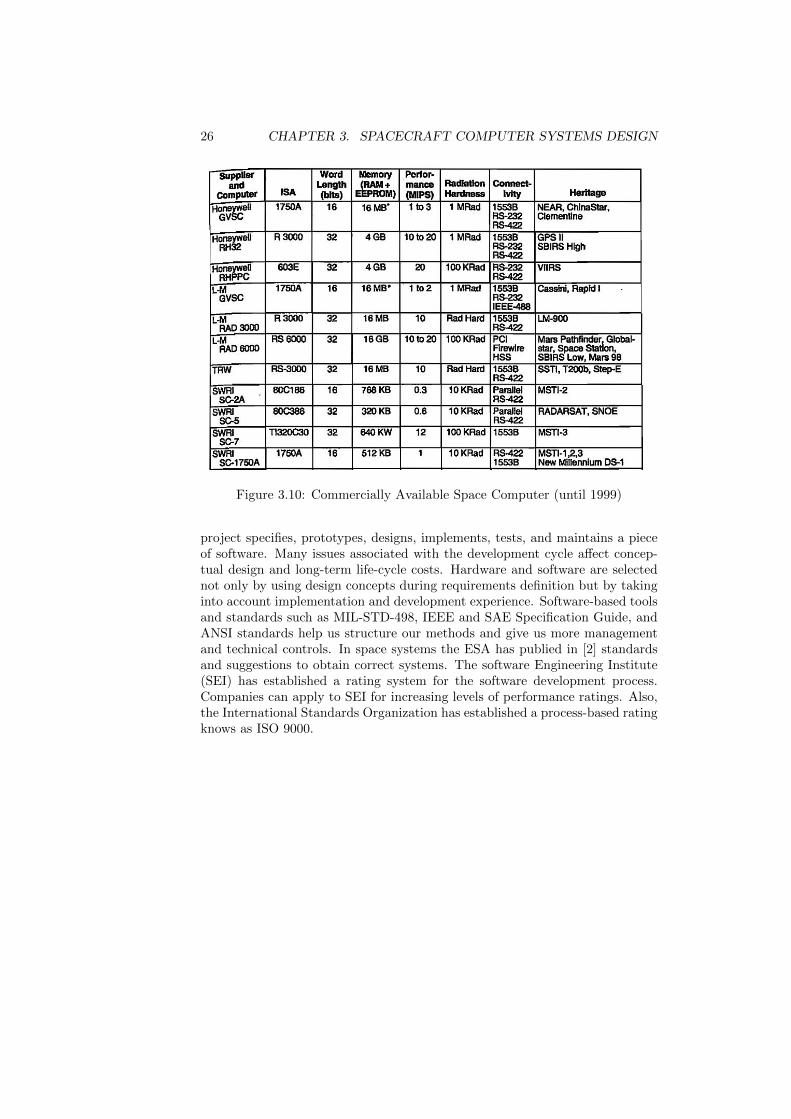
which meets all the basic needs, as well as the spare allocation, and the requiredsupport environment. Each computer considered must have suitable system soft-ware (operating system or kernel and built-in functions such as mathematics).Some examples of Space computer are shown in Figure 3.10. Space Comput-ers can be purchased or developed. In order to avoid paying the nonrecurringdevelopment costs, and incurring schedule risks space computers are generallypurchased. Large aerospace corporations have all the resources required to de-sign and test a computer for spacial application. Educational institutions, onthe other hand, may make the same choice, not to save money, but because theprocess meets an educational objective and because reliability requirements arenot stringent. The processor selected must meet the resource estimation thathas been calculated based on the software functions required to meet missionobjectives. If possible each candidate computer, or its engineering developmentunit equivalent, should be bench-marked against the relevant applications.
3.7 Integration and Test
Testing is an important and fundamental part in the system developing. Testingincludes all activities that increase confidence in the system’s performance. Itensures that we have met requirements and that anything happening beyondthese requirements does no harm to the system, preserving specified functions.Testing must be rigorous at all stages from the unit level to the system level.Even once operational, the system needs general testing to ensure it continuesto perform as required. This testing is often referred to as on-orbit check-outand calibration.
3.8 Life-Cycle Support and Standads
As in any other engineering discipline, software engineering also has some struc-tured models for software development. A life cycle is the sequence in which a
26 CHAPTER 3. SPACECRAFT COMPUTER SYSTEMS DESIGN
Figure 3.10: Commercially Available Space Computer (until 1999)
project specifies, prototypes, designs, implements, tests, and maintains a pieceof software. Many issues associated with the development cycle affect concep-tual design and long-term life-cycle costs. Hardware and software are selectednot only by using design concepts during requirements definition but by takinginto account implementation and development experience. Software-based toolsand standards such as MIL-STD-498, IEEE and SAE Specification Guide, andANSI standards help us structure our methods and give us more managementand technical controls. In space systems the ESA has publied in [2] standardsand suggestions to obtain correct systems. The software Engineering Institute(SEI) has established a rating system for the software development process.Companies can apply to SEI for increasing levels of performance ratings. Also,the International Standards Organization has established a process-based ratingknows as ISO 9000.

Chapter 4
Documentation andInterfaces
Documentation and Interfaces are part of all space system design, both groundsegment and fly segment have Interfaces and Documentation that support thenormal operation of the system. I chose to talk about them in a separatedchapter to give them the necessary importance and to address this topics in amore general way.
4.1 Documentation
This two section Documentation and Interfaces not only are present in the flysegment or in the spacecraft building, but also are present in the ground segmentdesign. I choose to fix these here because
The other main branch that conform a System, in addition to the softwareand hardware, is the documentation (figure 3.2). Computer systems consist ofhardware, software, their documentation and Interface definitions and documen-tation. Requirements Specification, Design Documents, Detailed Design Docu-ments, Interfaces Control Documents, are examples of documentation requiredin the development of a correct system by the space engineering. Moreover, allstep in the life cycle[27] of a system have to be accompanied by the correspond-ing documentation. Particularly the European Spatial Agency (ESA) proposesstandards that define softwares practises that must be applied in all the Agencyprojects. For example, the ESA PSS-05-0 [2] document describes the softwareengineering standards to be applied for all deliverable software implemented forthe European Space Agency, either in house or by industry. As it, there areseveral documentation guides provided by ESA to guide the develop of a sys-tem. In the figure 4.1 is shown the ESA documentation Tree. This tree showsthe complete name of the documents availables and publied by ESA.
Each document is given an identifier that follows the protocol: ESA PSS-05[-level 2 number][-level 3 number] PSS stands for Procedures, Specificationsand Standards’. The first field, defines the subject area as 05’, softwareengineering’. The number of numeric fields in the identifier defines the level(e.g. ESA PSS-05-05-02 is a level 3 document).
27

28 CHAPTER 4. DOCUMENTATION AND INTERFACES
Figure 4.1: The ESA PSS-05-0 Document Tree
Level 1 contains one and only one document, ESA PSS-05-0, which is a manda-tory standard for all ESA projects.
Level 2 documents offer guidance in carrying out the standard practices de-scribed in ESA PSS-05-0. They repeat mandatory practices stated in ESAPSS-05-0 (with cross-references) and do not define any new mandatory prac-tices.
Level 3 documents exist to:
• contain optional material;
• partition material in a higher level document into more manageable quan-tities.
4.1.1 ESA software engieeniering
ESA PSS-05-0 divides the software engineering activity into two parts: theproducts themselves and the procedures used to make them.
The system process of production is partitioned into six phases:
• User Requirements Definition;

4.1. DOCUMENTATION 29
• Software Requirements Definition;
• Architectural Design;
• Detailed Design and Production;
• Transfer;
• Operations and Maintenance.
The UR phase can be called the problem definition phase’ of the life cycle. Thephase refines an idea about a task to be performed using computing equipment,into a definition of what is expected from the computer system. [10]
The first phase of the software development life cycle is the Software Require-ments Definition Phase’ (SR phase). Activities and products are examined inthe review’ (SR/R) at the end of the phase. SR. The SR phase can be called theproblem analysis phase’ of the life cycle. The user requirements are analysedand software requirements are produced that must be as complete, consistentand correct as possible.[8]
The second phase of the life cycle is the ’Architectural Design Phase’ (ADphase). Activities and products are examined in the ’AD review’ (AD/R) atthe end of the phase. The AD phase can be called the ’solution phase’ of the lifecycle because it defines the software in terms of the major software componentsand interfaces. The ’Architectural Design’ must cover all the requirements inthe SRD. [5]
The third phase of the life cycle is the Detailed Design and Production Phase’(DD phase). Activities and products are examined in the review’ (DD/R) atDD the end of the phase. The DD phase can be called the implementationphase’ of the life cycle because the developers code, document and test thesoftware after detailing the design specified in the ADD.[6]
The fourth and last phase of the software development life cycle is the Transfer(TR) phase. The Transfer Phase can be called the handover phaseof the lifecycle because the developers release the software to the users. The software isinstalled on the target computer system and acceptance tests are run to validateit. Activities and products are reviewed by the Software Review Board (SRB)at the end of the phase.[9]

30 CHAPTER 4. DOCUMENTATION AND INTERFACES
The software enters practical use in the next and last phase of the softwarelife cycle, the ’Operations and Maintenance’ (OM) phase. The OM Phase isthe ’operational’ phase of the life cycle in which users operate the softwareand utilise the end products and services it provides. The developers providemaintenance and user support until the software is finally accepted, after whicha maintenance organisation becomes responsible for it.[7]
The ESA PSS-05-0 requires that software be verified during every phase of itsdevelopment life cycle and validated when it is transferred. These activities arecalled ’Software Verification and Validation’ (SVV). Each project must defineits Software Verification and Validation activities in a Software Verification andValidation Plan (SVVP).[4]
ESA PSS-05-0 requires that all software projects assure that products and pro-cedures conform to standards and plans. This is called Software Quality Assur-ance’ (SQA). Projects must define their software quality assurance activities ina Software Quality Assurance Plan (SQAP).[3]
4.2 Interfaces
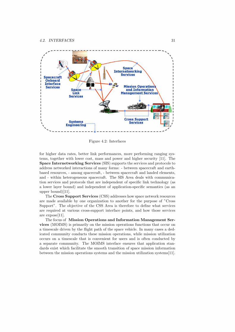
It is important, to take into account the interaction between differents elementsthat are part of the whole space system. Systems are divided into subsystemsand these are divided into units. How units talk toghether (protocols), whatservices they offer to the other ones, and the specification and documentationof both aspects is known as interface. Furthermore,these interactions have thetask of assurance the correct communication between space system components.There are many interfaces sourrounding the whole system. As it is shown in thefigure 4.2 ,interfaces play an important role not only communicating ground seg-ment with fly segment but inside them interfacing correctly each commponent.Formaly, the meaning of ”interfacing” should be understood as the specifica-tion of protocols and standards to obtain the correct component interaction.Regarding the figure 4.2 a short description of each one of them in providednext:
The Spacecraft Onboard Interface Services Area (SOIS) supports stan-dard development activities to improve the spacecraft flight segment data sys-tems design and development process by defining generic services that will sim-plify the way flight software interacts with flight hardware and permitting in-teroperability and reusability both for the benefit of Agencies and Industrialcontractors. Generally these kind of interfaces refer to data buses, and the wayin which they are built (see chapter 3, section 3.2 Architecture) [11] A spacelink interconnects a spacecraft with its ground support system or with anotherspacecraft. Agencies new generations of space missions require telecommandand telemetry capabilities beyond current technologies. These new needs are
4.2. INTERFACES 31
Figure 4.2: Interfaces
for higher data rates, better link performances, more performing ranging sys-tems, together with lower cost, mass and power and higher security [11]. TheSpace Internetworking Services (SIS) supports the services and protocols toaddress networked interactions of many forms: - between spacecraft and earth-based resources, - among spacecraft, - between spacecraft and landed elements,and - within heterogeneous spacecraft. The SIS Area deals with communica-tion services and protocols that are independent of specific link technology (asa lower layer bound) and independent of application-specific semantics (as anupper bound)[11].
The Cross Support Services (CSS) addresses how space network resourcesare made available by one organization to another for the purpose of ”CrossSupport”. The objective of the CSS Area is therefore to define what servicesare required at various cross-support interface points, and how those servicesare expose[11].
The focus of Mission Operations and Information Management Ser-vices (MOIMS) is primarily on the mission operations functions that occur ona timescale driven by the flight path of the space vehicle. In many cases a ded-icated community conducts these mission operations, while mission utilizationoccurs on a timescale that is convenient for users and is often conducted bya separate community. The MOIMS interface ensures that application stan-dards exist which facilitate the smooth transition of space mission informationbetween the mission operations systems and the mission utilization systems[11].

32 CHAPTER 4. DOCUMENTATION AND INTERFACES

Chapter 5
Conclusion
Throughout this work I have summarized several options to take care aboutthe design any space system. There is a very wide variety of things to takeinto account when designing a space system and software engieeniering mustto be applied. The design must include two important aspects: the groundsegment and fly segment. To meet the objectives of the mission, it is necessaryto have a correct design of both segments, with their components: hardware,software and documentation and interfaces. A poor design strategy involving asystem is more prone to bugs and instability. Two examples of architectures forthe ground segment have been seen as well as the main components of them.Concluding that the task of developing a sustainable space system throughoutthe mission depends almost exclusively on a correct design. As we can think,the concepts used in the design of an space system are the same ones used inthe development of common system software which are addressed in numerousbooks on software engineering. It is important to highlight that to start thewhole space system from scratch is not always the best alternative.
There is a trade-off between cost and benefit which is important to take careof. In fact, it has been shown that it will be better (from the standpoint ofcost-performance) to use market services/components in some particular cases:AFSCN bring to clients (NASA, NOAA, etc) infrastructure dedicated which hasbeen already developed used by the clients to reduce cost and labor. Regardingcomponents, another example is the one shown in previuos chapters, whichexplain, that except in academic environments or highly specialized companies,is convenient to use commercially available components (processors, buses, etc.)insted of building the components from scratch.
An aspect that called my attention and contratry to what intuition maymake me belive is that aspects of components like processor power onboardthe satellite is far below the ones existing in current personal computers andlaptops. A possible reason may be atributed to the gap between the start andthe end times of a mission. The processor choice is done by the start time of amission, then at end time of the mission (may be five years ahead) this choicebecames obsolete comparing the current technologies. Another reason could beattributed to the adverse conditions that processors have to face in the spaceenvironment, it could make priorise stability to velocity and calculation power.
It is important to remark the importance that documentation and interfaceshave in the whole system. Without a correct interfaces definition the intercon-
33

34 CHAPTER 5. CONCLUSION
nection between subsystems is hard and in some cases impossible to perform.A poor documentation not only makes hard the maintenance of the system butthat, it difficult also the system construction. Let think that in a space sys-tem development there are a lot of workers involved and documentation makesnot only the understanding of the whole system easy, but the understanding ofsubsystems and components easy.
In a nutshell, it is completely clear that the success or failure of the mis-sion will go together with proper design of spacial systems or an incorrect orinappropriate design of them.

Appendix A
Appendix
A.1 TacSat-2
TacSat-2 is a small satellite for developing low-cost, customized and rapidly de-ployable space capabilities for war-fighters. Work on TacSat-2 is being done atthe Air Force Research Laboratory with help from the Naval Research Labora-tory. This TacSat demo was scheduled for 2007 as the first proof of concept forjoint war-fighters space (JWS). Plans are to provide the Joint Force Comman-der with an operational capability by 2010 [22]. One objective of the TacSat-2experiment is to develop an understanding of the requirements for and limi-tations of rapid deployment. This includes launch vehicle integration, launch,and on-orbit checkout of the satellite. A second objective is to understand therequirements and limitations for the rapid development of new spacecraft andpayloads[22]. The payloads that primarily address operationally relevant tacti-cal capabilities include the Target Indicator Experiment (TIE) supplied by navalresearch laboratory (NRL) and the imaging system supplied by Nova Biomimet-ics and SAIC. The TIE payload is an improved version of the primary payloadcarried by TacSat-1. The TIE payload performs real-time signal geolocationand SEI of radio frequency (RF) signals using space and air-based collectionplatforms. It is also capable of collecting the Automated Identification System(AIS) signal now required on large ships for port safety and homeland defense.The TIE payload is also reprogrammable on-orbit for acquiring new targets.The TacSat-2 imaging system has panchromatic, red, green, and blue sensorswith a ground sample distance (GSD) of approximately 1 meter. Figure A.1shows the TacSat 2 pre-flight testing.
35

36 APPENDIX A. APPENDIX
Figure A.1: The TacSat 2 JWS D1 spacecraft undergoes pre-flight testing.

Bibliography
[1] Agarwal, R., Sakthivel, S., and Tanniru, M. Knowledge-based ap-proach to structural integrity verification in requirements analysis and log-ical system specification. Knowledge-Based Systems 6, 3 (1993), 165 – 173.17
[2] BSSC-ESA. Esa software engineering standards issue 2 - technical name:Esa pss-05-0 issue 2. Tech. rep., 8-10, rue Mario-Nikis, 75738 PARISCEDEX, France, 1994. 26, 27
[3] BSSC-ESA. Guide to software quality assurance - technical name: Esapss-05-11. Tech. rep., 8-10, rue Mario-Nikis, 75738 PARIS CEDEX, France,1995. 30
[4] BSSC-ESA. Guide to software verification and validation - technical name:Esa pss-05-10. Tech. rep., 8-10, rue Mario-Nikis, 75738 PARIS CEDEX,France, 1995. 30
[5] BSSC-ESA. Guide to the software architectural design phase - technicalname: Esa pss-05-04. Tech. rep., 8-10, rue Mario-Nikis, 75738 PARISCEDEX, France, 1995. 29
[6] BSSC-ESA. Guide to the software detailed design and production phase- technical name: Esa pss-05-05. Tech. rep., 8-10, rue Mario-Nikis, 75738PARIS CEDEX, France, 1995. 29
[7] BSSC-ESA. Guide to the software operations and maintenance phase -technical name: Esa pss-05-07. Tech. rep., 8-10, rue Mario-Nikis, 75738PARIS CEDEX, France, 1995. 30
[8] BSSC-ESA. Guide to the software requirements definition phase - techni-cal name: Esa pss-05-03. Tech. rep., 8-10, rue Mario-Nikis, 75738 PARISCEDEX, France, 1995. 19, 29
[9] BSSC-ESA. Guide to the software transfer phase - technical name: Esapss-05-06. Tech. rep., 8-10, rue Mario-Nikis, 75738 PARIS CEDEX, France,1995. 29
[10] BSSC-ESA. Guide to the user requirements definition phase - techni-cal name: Esa pss-05-2. Tech. rep., 8-10, rue Mario-Nikis, 75738 PARISCEDEX, France, 1995. 19, 29
[11] CCSDS. http://public.ccsds.org/default.aspx. The Consultative Commit-tee for Space Data Systems. 30, 31
37

38 BIBLIOGRAPHY
[12] Fortescue, P., Stark, J., and Swinerd, G. Spacecraft system engi-neering, third edition ed. Jhon Wiley and Sons Ltd., 2003, ch. SpacecraftStructures. 19
[13] Fortescue, P., Stark, J., and Swinerd, G. Spacecraft Systems Engi-neering, third edition ed. Jhon Wiley and Sons Ltd., 2003, ch. Introduction.1, 2
[14] Fortescue, P., Stark, J., and Swinerd, G. Spacecraft Systems En-gineering, third edition ed. Jhon Wiley and Sons Ltd., 2003, ch. GroundStations. 5, 8
[15] Fortescue, P., Stark, J., and Swinerd, G. Spacecraft Systems Engi-neering, third edition ed. Jhon Wiley and Sons Ltd., 2003, ch. The Space-craft Environment and its effects on Design. 23
[16] Gilb, T., and Finzi, S. Principles of Software Engineering Management.Addison-Wesley, 1988. 11
[17] Hodges, L., and Woll, R. Air force satellite control network (afscn)support for operational responsive space (ors). 6th Responsive Space Con-ference RS6-2008-1006 (2008). 14
[18] Ko, Y., Park, S., Seo, J., and Choi, S. Using classification techniquesfor informal requirements in the requirements analysis-supporting system.Information and Software Technology 49, 11-12 (2007), 1128 – 1140. 17
[19] Larson, W., and Wertz, J. Space Mission Analysis and Design. Mi-crocosm Press, 1999, ch. Ground System Design and Sizing. 2, 5, 8, 11
[20] Larson, W. J., and R, W. J. Space Mission Analysis and Design.Microcosm Press, 1999, ch. Spacecraft Computer Systems. 19, 20, 22, 23
[21] Munson, J. C. Software faults, software failures and software reliabil-ity modeling. Information and Software Technology 38, 11 (1996), 687 –699. Software Maintenance Selected papers from the Centre for SoftwareReliability Annual Conference. 23
[22] NASA. http://www.nasa.gov/mission pages/tacsat-2/main/. 35
[23] Oei, I., and Mirra, C. Europe’s human research experiments integrationon the international space station. Acta Astronautica (2008). 1
[24] Oglietti, M. Domain independent planning for space: Building a bridgefrom both shores. International Workshop on Planning and Scheduling forSpace (2002). 15, 16
[25] Pfleeger, S. L., and Atlee, J. M. Software Engineering: Theory andPractice. Prentice Hall, 2010. 11
[26] Prcigout, J.-P., and Favaro, J. The european space software devel-opment environment. Annual Review in Automatic Programming 16, Part2 (1992), 95 – 102. Experience with the management of software projects1992. 2

BIBLIOGRAPHY 39
[27] Tausworthe, R. C. Concepts and tools for the software life cycle. Com-puter Physics Communications 38, 2 (1985), 135 – 148. 27