commander 1900 series agents manual circular … pdfs/im_c1900-agn_7.pdfcircular chart recorders...
TRANSCRIPT

COMMANDER 1900 SeriesCircular Chart Recorders
Agents Manual
All Versions
COMMANDER 1900
100.3 198.5dEGF
OP54.5 200.5
!50.8

0255
ABB AUTOMATION
The Company
ABB Automation is an established world force in the design and manufacture ofinstrumentation for industrial process control, flow measurement, gas and liquid analysis andenvironmental applications.
As a part of ABB, a world leader in process automation technology, we offer customersapplication expertise, service and support worldwide.
We are committed to teamwork, high quality manufacturing, advanced technology andunrivalled service and support.
The quality, accuracy and performance of the Company’s products result from over 100 yearsexperience, combined with a continuous program of innovative design and development toincorporate the latest technology.
The NAMAS Calibration Laboratory No. 0255 is just one of the ten flow calibration plantsoperated by the Company, and is indicative of ABB Automation’s dedication to qualityand accuracy.
Use of Instructions
Warning.An instruction that draws attention to the risk of injury ordeath.
Caution.An instruction that draws attention to the risk of damage tothe product, process or surroundings.
Note.Clarification of an instruction or additional information.
Information.Further reference for more detailed information ortechnical details.
Although Warning hazards are related to personal injury, and Caution hazards are associated with equipment or property damage,it must be understood that operation of damaged equipment could, under certain operational conditions, result in degradedprocess system performance leading to personal injury or death. Therefore, comply fully with all Warning and Caution notices.
Information in this manual is intended only to assist our customers in the efficient operation of our equipment. Use of this manualfor any other purpose is specifically prohibited and its contents are not to be reproduced in full or part without prior approval ofMarketing Communications Department, ABB Automation.
Health and SafetyTo ensure that our products are safe and without risk to health, the following points must be noted:
1. The relevant sections of these instructions must be read carefully before proceeding.
2. Warning labels on containers and packages must be observed.
3. Installation, operation, maintenance and servicing must only be carried out by suitably trained personnel and in accordance with theinformation given.
4. Normal safety precautions must be taken to avoid the possibility of an accident occurring when operating in conditions of high pressureand/or temperature.
5. Chemicals must be stored away from heat, protected from temperature extremes and powders kept dry. Normal safe handling proceduresmust be used.
6. When disposing of chemicals ensure that no two chemicals are mixed.
Safety advice concerning the use of the equipment described in this manual or any relevant hazard data sheets (where applicable) may beobtained from the Company address on the back cover, together with servicing and spares information.
BS EN ISO 9001
St Neots, U.K. – Cert. No. Q5907Stonehouse, U.K. – Cert. No. FM 21106
EN 29001 (ISO 9001)
Lenno, Italy – Cert. No. 9/90A
Stonehouse, U.K.
REGISTERE
D
1
Section Page
1 INTRODUCTION .......................................................... 1
2 PREPARATION ............................................................ 22.1 Agents Upgrade Kit Identification ...................... 2
3 FITTING ADDITIONAL PEN(S) .................................... 53.1 Fitting a Standard Input/Output Module ............. 53.2 Fitting a Motor and Pen Assembly ..................... 73.3 Fitting a Display Board ...................................... 83.4 Changing the Software Configuration ................ 9
4 RECORDER TO CONTROLLER UPGRADE ............ 104.1 Fitting a Controller Faceplate .......................... 104.2 Fitting a Software Key ..................................... 114.3 Changing the Software Configuration .............. 12
5 FITTING A TRUE TIME EVENT MARKER ................ 135.1 Fitting a Motor and
True Time Event Marker .................................. 135.2 Changing the Software Configuration .............. 14
6 FITTING ADDITIONAL MODULES ............................ 156.1 Fitting an Input and Relay Module ................... 15
7 ADDING ADVANCED SOFTWARE OPTIONS .......... 177.1 Software Key Identification .............................. 177.2 Fitting a Software Key ..................................... 18
8 COMMISSIONING LEVEL ......................................... 198.1 Set Up Instrument Type Page
(All Models Except C1950 SeriesPasteurizer Versions) ...................................... 20
8.2 Set Up Instrument Type Page(C1950 Series Pasteurizer Versions Only) ...... 22
8.3 Company Standard Page ................................ 238.4 Input Assignment Page .................................... 248.5 Pen Assignment Page ..................................... 258.6 Input Calibration Page ..................................... 268.7 Output Calibration Page .................................. 288.8 Pen Calibration Page ....................................... 298.9 Display Set Up Page ....................................... 308.10 Relay Test Page ............................................... 308.11 Digital Input Test Page ..................................... 318.12 Output Test Page ............................................. 318.13 Diagnostics Page ............................................. 32
9 INSTRUMENT REPAIR .............................................. 339.1 Non-volatile Memory ICs ................................. 339.2 Microprocessor Board Replacement ............... 33
CONTENTS 1 INTRODUCTION
SPECIFICATION
PROGRAMMING
OPERATION
INSTALLATION
Part No.
IM/C1900–CON
CONTROLLER
PACK
MODBUS (RTU)
Serial Adaptors
Serial Connections
Programming Page
Modbus Functions
Part No.IM/C1900–MOD
Part No.IM/C1900–ADV
ADVANCED SOFTWAREOPTIONS
Totalizer Option
Timer Option
Ramp/Soak Option
Maths Option
Modbus Registers
AGENTS MANUALKit Identification
Instrument UpgradesPen Upgrades
Part No.IM/C1900–AGN
Fitting Modules
Commisioning Level
Fitting Event Marker
SPECIFICATION
PROGRAMMING
OPERATION
INSTALLATION
Part No.
IM/C1900–REC
RECORDER
PACK
A – Standard Manual Packs
B – Supplementary Manuals
Fig. 1.1 COMMANDER 1900 Documentation
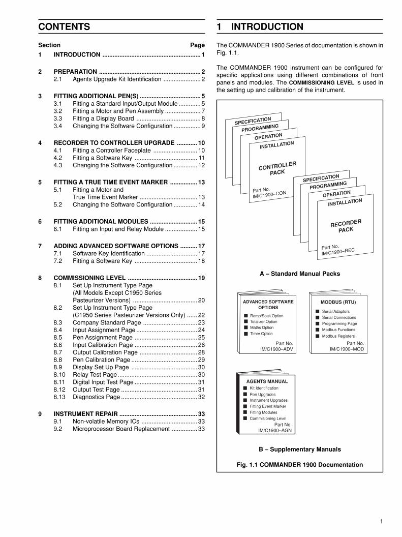
The COMMANDER 1900 Series of documentation is shown inFig. 1.1.
The COMMANDER 1900 instrument can be configured forspecific applications using different combinations of frontpanels and modules. The COMMISSIONING LEVEL is used inthe setting up and calibration of the instrument.
2
2 PREPARATION
HAS BEEN IN
STALLED IN THIS IN
STRUMENT
WHEN CONTACTING A
BB KENT–TAYLOR
REFER TO BOTH IN
STRUMENT SERIAL N
o.
AND THIS UPGRADE K
IT No.
UPGRADE KIT
Terminal Board (C1900/0305)
Pen Motor (C1900/0070)Pen 2 or 3
I/O Module(C1900/0255)
Membrane Overlay(including Membrane switch)
(C1900/0236)
Display Board(C1900/0275)
Small Parts PackScrew x2 (B8573)Screw x2 (B5974)Washer x2 (B6421)Cable tie x2 (B5634)Ribbon Cable (PXR105/0176)
Label(C1900/0204)
Pen Motor (C1900/0071)Pen 4
Kit 2 Kit 2A
ER/C Type Chart – Pen Arm (C1900/0076)
PX105 and PXR105 Type Chart – Pen Arm(C1900/0075)
HAS BEEN IN
STALLED IN THIS IN
STRUMENT
WHEN CONTACTING A
BB KENT–TAYLOR
REFER TO BOTH IN
STRUMENT SERIAL N
o.
AND THIS UPGRADE K
IT No.
UPGRADE KIT
Terminal Board(C1900/0305)
Pen Motor (C1900/0070)Pen 2 or 3
ER/C Type Chart – Pen Arm (C1900/0076)
I/O Module(C1900/0255)
Small Parts PackScrew x2 (B5974)Washer x2 (B6421)Cable tie x2 (B5634)
Label(C1900/0204)
Pen Motor (C1900/0071)Pen 4
Kit 1 Kit 1A
PX105 and PXR105 Type Chart – Pen Arm(C1900/0075)
rebmuNtiK esopruPrebmuNtraP
trahCepyTC/RErebmuNtraP
trahCepyT501RXPdna501XP
1tiK edargpunepeerhtroowT 0270/0091C 6270/0091C
A1tiK edargpunephtruoF 1270/0091C 7270/0091C
2tiK )yalrevOredroceR(edargpuneP 2270/0091C 8270/0091C
A2tiK )yalrevOredroceR(edargpunephtruoF 3270/0091C 9270/0091C
3tiK edargpurellortnoCotredroceR 4270/0091C 4270/0091C
4tiK )yalrevOrellortnoC(edargpunepowtotenO 5270/0091C 0370/0091C
5tiK rekramtneveemiteurT 8070/0091C 1370/0091C
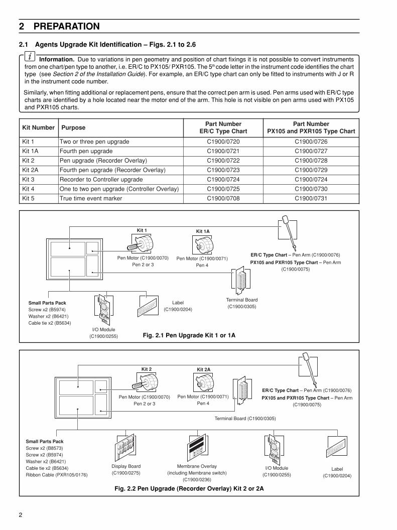
2.1 Agents Upgrade Kit Identification – Figs. 2.1 to 2.6
Information. Due to variations in pen geometry and position of chart fixings it is not possible to convert instrumentsfrom one chart/pen type to another, i.e. ER/C to PX105/ PXR105. The 5th code letter in the instrument code identifies the charttype (see Section 2 of the Installation Guide). For example, an ER/C type chart can only be fitted to instruments with J or Rin the instrument code number.
Similarly, when fitting additional or replacement pens, ensure that the correct pen arm is used. Pen arms used with ER/C typecharts are identified by a hole located near the motor end of the arm. This hole is not visible on pen arms used with PX105and PXR105 charts.
Fig. 2.1 Pen Upgrade Kit 1 or 1A
Fig. 2.2 Pen Upgrade (Recorder Overlay) Kit 2 or 2A
3
2 PREPARATION…
HAS BEEN IN
STALLED IN THIS IN
STRUMENT
WHEN CONTACTING A
BB KENT–TAYLOR
REFER TO BOTH IN
STRUMENT SERIAL N
o.
AND THIS UPGRADE K
IT No.
UPGRADE KIT
Pen Motor (C1900/0071) Pen 4
Small Parts PackScrew x2 (B5974)Washer x2 (B6421)Cable tie x2 (B5634)Pen capsule (violet) C1900/0123
Label(C1900/0204)
ER/C Type Chart – Pen Arm (C1900/0078)
PX105 and PXR105 Type Chart – Pen Arm(C1900/0077)
HAS BEEN IN
STALLED IN THIS IN
STRUMENT
WHEN CONTACTING A
BB KENT–TAYLOR
REFER TO BOTH IN
STRUMENT SERIAL N
o.
AND THIS UPGRADE K
IT No.
UPGRADE KIT
Membrane Overlay(including Membrane Switch)
(C1900/0235)
Label(C1900/0204)
Software Key(C1900/0330)
HAS BEEN IN
STALLED IN THIS IN
STRUMENT
WHEN CONTACTING A
BB KENT–TAYLOR
REFER TO BOTH IN
STRUMENT SERIAL N
o.
AND THIS UPGRADE K
IT No.
UPGRADE KIT
8.8.
8.8.
8.8. 8.8.
8.8.
8.8.
Terminal Board (C1900/0305)
Pen Motor (C1900/0070) Pen 2 or 3
I/O Module(C1900/0255)
Membrane Overlay(including Membrane Switch)
(C1900/0235)
Display Board(C1900/0275)
Small Parts PackScrew x2 (B8573)Screw x2 (B5974)Washer x2 (B6421)Cable tie x2 (B5634)Ribbon Cable (PXR105/0176)
Label(C1900/0204)
ER/C Type Chart – Pen Arm (C1900/0076)
PX105 and PXR105 Type Chart – Pen Arm(C1900/0075)
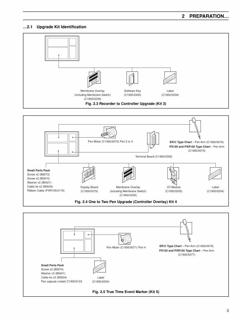
…2.1 Upgrade Kit Identification
Fig. 2.3 Recorder to Controller Upgrade (Kit 3)
Fig. 2.4 One to Two Pen Upgrade (Controller Overlay) Kit 4
Fig. 2.5 True Time Event Marker (Kit 5)

4
…2 PREPARATION
Used to program all Channels
CH1
CH2
CH3
CH4
AL1 AL2 AL3 AL4
303
404
Record Blank
CH1
CH2
CH3
CH4
AL1 AL2 AL3 AL4
303
404
CH1
CH2
CH3
CH4
AL1 AL2 AL3 AL4
303
404CH1
CH2
CH3
CH4
AL1 AL2 AL3 AL4
303
404
CH1
CH2
CH3
CH4
AL1 AL2 AL3 AL4
303
404CH1
CH2
CH3
CH4
AL1 AL2 AL3 AL4
303
404
1911J
1912J
1913J
1914J
Kit 1
Kit 2
Kit 1A
Al RMT AT MAN
100.3
100.5Al RMT AT MAN
200.3
200.5
Al RMT AT MAN
100.3
100.5Al RMT AT MAN
200.3
200.5CH1
CH2
CH3
CH4
AL1 AL2 AL3 AL4
303
404
Al RMT AT MAN
100.3
100.5Al RMT AT MAN
200.3
200.5CH1
CH2
CH3
CH4
AL1 AL2 AL3 AL4
303
404
CH1
CH2
CH3
CH4
AL1 AL2 AL3 AL4
303
404Al RMT AT MAN
200.3
200.5
CH1
CH2
CH3
CH4
AL1 AL2 AL3 AL4
303
404Al RMT AT MAN
200.3
200.5
CH1
CH2
CH3
CH4
AL1 AL2 AL3 AL4
303
404Al RMT AT MAN
200.3
200.5CH1
CH2
CH3
CH4
AL1 AL2 AL3 AL4
303
404
1911R
1912R 1922R
1913R 1923R
1914R 1924R
Control
Al RMT AT MAN
200.3
200.5
Kit 2
Kit 1
Kit 2A Kit 1A
Kit 2
Kit 4
Kit 3
Record
Record
Record
Record
Record
Record
Record
Record
Record
Record
Blank
Blank Blank
Blank Blank
Blank
Blank
Blank
Blank
Blank
BlankControl
Control
Control
ControlControl
Control Control
Control Control
…2.1 Upgrade Kit IdentificationIdentify the upgrade kit required and the relevent faceplate positions as detailed in Fig 2.6
Fig. 2.6 Upgrade Kit Identification and Faceplate Combinations

5
3 FITTING ADDITIONAL PEN(S)
AdditionalFunctions
AdditionalFunctions
Channel 1(Red Pen)
Channel 2(Green Pen)
Channel 3(Blue Pen)
Module Positions 1 2 3 4 5 6
Channel 4(Black Pen, Violet Event Penor Additional Functions)
To fit additional pen(s) perform all the following procedures:a) Fit module in required position – see Section 3.1.b) Fit the required motor and pen assembly – see Section 3.2.c) Fit the required display board – see Section 3.3.d) Access the COMMISSIONING LEVEL to change the instrument type and re-configure instrument – see Section 3.4.
3.1 Fitting a Standard Input/Output Module – Fig. 3.1 and 3.2
Warning. Before making any connections, ensure that the power supply, any high voltage-operated control circuitsand high common mode voltages are switched off.
a) Disconnect all power supplies from the instrument.
b) Identify the module position – see Fig. 3.1.
Note. Module positions 2 and 3 can also be used for additional Input andOutput modules (module types 1 and 2) for use with math functions.
Information. The module type is marked on the component side of thep.c.b.
Fig. 3.1 Module Positions and Functions

6
…3 FITTING ADDITIONAL PEN(S)
Plug in Module
Identify the terminalboard and moduleusing position labels
Ensure terminal board islocated correctly in clip
Locate terminal board intothe main processor boardsupports
1
2
3
4
…3.1 Fitting a Standard Input/Output Modulec) If necessary, remove and discard knockout(s) from instrument case.
d) Carefully clean out hole(s) and ensure all debris is removed from inside the instrument.
e) Route the leads and cables into the case.
f) Identify the module position.
g) Fit the required module as detailed in Fig. 3.2.
On completion proceed to Section 3.2.
Note. Connections to the terminal block can bemade before or after fitting to the main p.c.b.
Caution. The terminal board is vulnerable toelectrostatic damage. Handle the board by its edgesonly and use an anti-static bench when fitting orremoving.
Fig. 3.2 Fitting a Standard Input/Output Module

7
3 FITTING ADDITIONAL PEN(S)…
Identify motor position(s) on the motor plate Locate the motor(s) inthe motor plate andsecure using two screwsand washers
Connect the motor(s) to the main processorboard, ensuring the green wire in the connectoris located on Pin 1 of the main processor board
Secure the motor wires using twocable ties. Refer to Step for cabletie positions
Fit pen(s), ensuring thepen arm is positionedabove its l ifter bar
Carefully remove thecable ties from the motorplate and motor wires
Motor 2 Connector
Motor 3 Connector
Motor 4 Connector
Adjust the pen pressure by removing the penarm from its yoke and bending the pen arm.Replace pen and re-check pressure.
1
2
3
1
2
3
Set pen pressure to 1 gramm
Pos
ition
1
Pos
ition
2
Pos
ition
3
Pos
ition
4
Pos
ition
5
Pos
ition
6
UPGRADE KIT
HAS BEEN INSTALLED IN THIS INSTRUMENTWHEN CONTACTING KENT-TAYLOR
REFER TO BOTH INSTRUMENT SERIAL NOAND THIS UPGRADE KIT NO
Fit upgrade label insidethe door gasket area
1
1
1
2
3
4
Bend from here
1
2
3
4
5
6
7
8
9
2
3.2 Fitting a Motor and Pen Assembly – Fig. 3.3a) Fit the required motor and pen assembly as detailed in Fig. 3.3.
On completion proceed to Section 3.3.
Fig. 3.3 Fitting a Motor and Pen Assembly

8
…3 FITTING ADDITIONAL PEN(S)
Secure the display board to the doorusing two self-tapping screws
Peel off blanking plate andremove any residue adhesiveusing petroleum ether
Link the display board to theadjacent display board using aribbon cable (PXR105/0170)
Connect the flexi-circuitcarefully to the displayboard
Replace the display cover byreversing steps , and
UPGRADE KIT
HAS BEEN INSTALLED IN THIS INSTRUMENTWHEN CONTACTING KENT-TAYLOR
REFER TO BOTH INSTRUMENT SERIAL NOAND THIS UPGRADE KIT NO
Fit upgrade label insidethe door gasket area
Open door
Loosen screw
Remove screw andslide the display coveraway from the door
Fit the self-adhesivespacer
Route the flexi-circuit of the new membraneswitch through the cutout in the door andfix the membrane overlay onto the door
MANAT
RMTAL
1 2 3
4
5
6
7 8
9
10
11
3 4 5
Note 2
Note 1
3.3 Fitting a Display Board – Fig. 3.4a) Fit the required display board as detailed in Fig. 3.4.
On completion proceed to Section 3.4.
Note 1.When fitting a display board in the left-most position(indicated), the door stay bracket must be removed toaccess the top right-hand display board securingscrew.
Note 2.Although the adhesive on the membrane overlay mustbe allowed to cure for a minimum of 2 hours, it isrecommended that the overlay is left for 24 hours (thefull cure time of the adhesive) before the switches areused.
Fig. 3.4 Fitting a Display Board
9
3 FITTING ADDITIONAL PEN(S)…
Pos
ition
1
Pos
ition
2
Pos
ition
3
Pos
ition
4
Pos
ition
5
Pos
ition
6
1
4
2
3
LK3
Disable Security
1
4
2
3
LK3
Enable Security
Position the security linkin the disable position
Select the ADVANCED CONFIGURATION LEVELAL RMT AT MAN
AL RMT AT MAN
OPrtOr
LEVEL
CONFIG
AdUNCd
AL RMT AT MAN
tYPE
INSt
Hold down the switch and switchsimultaneously to access the COMMISSIONING LEVEL
First frame ofCOMMISSIONING LEVEL
1
2
3
Fig. 3.5 Access to Commissioning Level
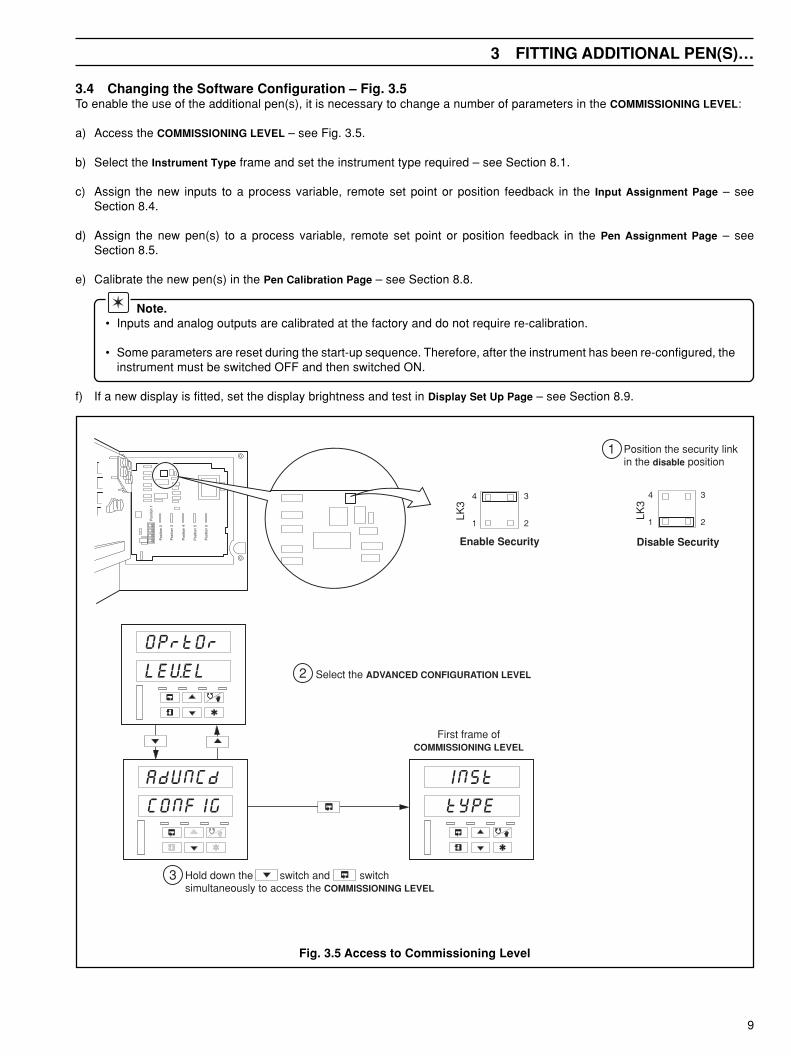
3.4 Changing the Software Configuration – Fig. 3.5To enable the use of the additional pen(s), it is necessary to change a number of parameters in the COMMISSIONING LEVEL:
a) Access the COMMISSIONING LEVEL – see Fig. 3.5.
b) Select the Instrument Type frame and set the instrument type required – see Section 8.1.
c) Assign the new inputs to a process variable, remote set point or position feedback in the Input Assignment Page – seeSection 8.4.
d) Assign the new pen(s) to a process variable, remote set point or position feedback in the Pen Assignment Page – seeSection 8.5.
e) Calibrate the new pen(s) in the Pen Calibration Page – see Section 8.8.
Note.• Inputs and analog outputs are calibrated at the factory and do not require re-calibration.
• Some parameters are reset during the start-up sequence. Therefore, after the instrument has been re-configured, theinstrument must be switched OFF and then switched ON.
f) If a new display is fitted, set the display brightness and test in Display Set Up Page – see Section 8.9.
10
4 RECORDER TO CONTROLLER UPGRADE
Refit the displayboard to the door
Route the flexi-circuit of the new membraneswitch through the cutout in the door andfix the membrane overlay onto the door
Re-connect ribbon cable(s)linking the display board toadjacent boards
Connect the flexi-circuit carefully tothe display board
Replace the display cover byreversing steps , and
MANAT
RMTAL
Peel off blanking plate andremove any residue adhesiveusing petroleum ether
Open door
Loosen screw
Remove screw andslide the display coveraway from the door
Fit the self-adhesivespacer
Loosen the two self-tapping screws securingthe display board to thedoor and remove thedisplay board.
Remove any cable(s)connecting the displayboard to adjacent boards.
1 2 3
4
5
6
7
8
9
10
12
11
3 4 5
Note 1
Note 2
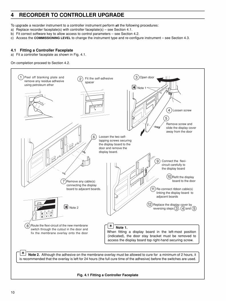
To upgrade a recorder instrument to a controller instrument perform all the following procedures:a) Replace recorder faceplate(s) with controller faceplate(s) – see Section 4.1.b) Fit correct software key to allow access to control parameters – see Section 4.2.c) Access the COMMISSIONING LEVEL to change the instrument type and re-configure instrument – see Section 4.3.
4.1 Fitting a Controller Faceplatea) Fit a controller faceplate as shown in Fig. 4.1.
On completion proceed to Section 4.2.
Note 1.When fitting a display board in the left-most position(indicated), the door stay bracket must be removed toaccess the display board top right-hand securing screw.
Note 2. Although the adhesive on the membrane overlay must be allowed to cure for a minimum of 2 hours, itis recommended that the overlay is left for 24 hours (the full cure time of the adhesive) before the switches are used.
Fig. 4.1 Fitting a Controller Faceplate

11
4 RECORDER TO CONTROLLER UPGRADE…
Identify the software keysockets on main processorboard
UPGRADE KIT
HAS BEEN INSTALLED IN THIS INSTRUMENTWHEN CONTACTING KENT-TAYLOR
REFER TO BOTH INSTRUMENT SERIAL NOAND THIS UPGRADE KIT NO
Fit upgrade label inside the door gasket area
1
2
3
Fit required softwarekey ensuring pins arealigned correctly
4.2 Fitting a Software Keya) Fit the required software key as shown in Fig. 4.2.
b) Switch on and configure the instrument using the Advanced Software Options manual.
On completion proceed to Section 4.3.
Caution. The software key is vulnerable toelectrostatic damage. Handle the board by its edgesonly.
Fig. 4.2 Fitting a Software Key
12
…4 RECORDER TO CONTROLLER UPGRADE
AL RMT AT MAN
AL RMT AT MAN
OPrtOr
LEVEL
CONFIG
AdUNCd
AL RMT AT MAN
tYPE
INSt
AL RMT AT MAN
OPtIOn
PAGE
AL RMT AT MAN
VErSON
CONtrL
11
2
3
5
69
10
6
7
8
9
10
11
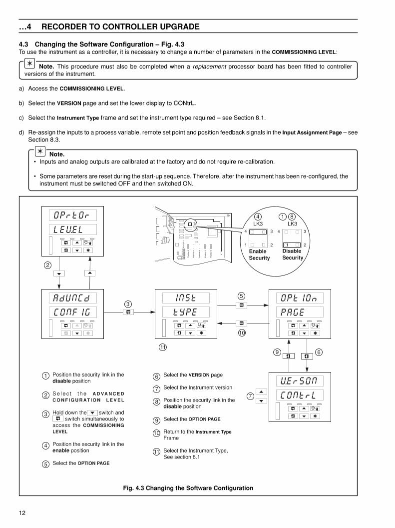
Select the VERSION page
Select the Instrument version
Position the security link in thedisable position
Select the OPTION PAGE
Return to the Instrument TypeFrame
Select the Instrument Type,See section 8.1
Position the security link in thedisable position
S e l e c t t h e A D VA N C E DC O N F I G U R AT I O N L E V E L
Hold down the switch and switch simultaneously toaccess the COMMISSIONINGLEVEL
Position the security link in theenable position
Select the OPTION PAGE
1
2
3
4
5
7
Pos
ition
1
Pos
ition
2
Pos
ition
3
Pos
ition
4
Pos
ition
5
Pos
ition
6 EnableSecurity
1
4
2
3
LK3
DisableSecurity
1
4
2
3
LK314 8
4.3 Changing the Software Configuration – Fig. 4.3To use the instrument as a controller, it is necessary to change a number of parameters in the COMMISSIONING LEVEL:
Note. This procedure must also be completed when a replacement processor board has been fitted to controllerversions of the instrument.
a) Access the COMMISSIONING LEVEL.
b) Select the VERSION page and set the lower display to CONtrL.
c) Select the Instrument Type frame and set the instrument type required – see Section 8.1.
d) Re-assign the inputs to a process variable, remote set point and position feedback signals in the Input Assignment Page – seeSection 8.3.
Note.• Inputs and analog outputs are calibrated at the factory and do not require re-calibration.
• Some parameters are reset during the start-up sequence. Therefore, after the instrument has been re-configured, theinstrument must be switched OFF and then switched ON.
Fig. 4.3 Changing the Software Configuration
13
5 FITTING A TRUE TIME EVENT MARKER
Identify motor position 4 on the motor plateLocate the motor in themotor plate and secureusing two screws andwashers
Connect the motor to the main processorboard ensuring the green wire in theconnector is located on Pin 1 of the mainprocessor board
Secure the motor wires using twocable ties. Refer to Step for cabletie positions
Fit true time event markerpen, ensuring the pen arm ispositioned above its lifter bar
Pos
ition
1
Pos
ition
2
Pos
ition
3
Pos
ition
4
Pos
ition
5
Pos
ition
6
Carefully remove cableties from the motor plateand motor wires
UPGRADE KIT
HAS BEEN INSTALLED IN THIS INSTRUMENTWHEN CONTACTING KENT-TAYLOR
REFER TO BOTH INSTRUMENT SERIAL NOAND THIS UPGRADE KIT NO
Adjust pen pressure by removing the penarm from its yoke and bending the pen arm.Replace pen and re-check pressure.
1
2
3
1
2
3
Set pen pressure to 1 gramm
Motor 4 Connector
1
4
Fit upgrade label insidethe door gasket area
Bend from here
1
2
3
4
5
6
7
8
9
2
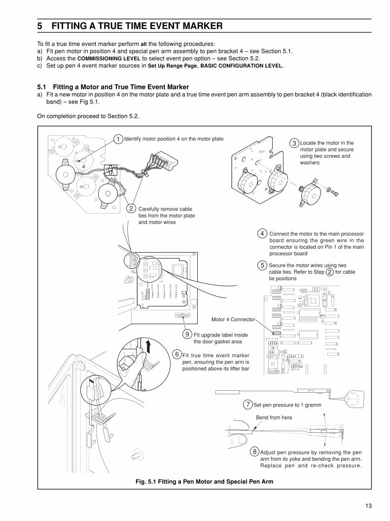
To fit a true time event marker perform all the following procedures:a) Fit pen motor in position 4 and special pen arm assembly to pen bracket 4 – see Section 5.1.b) Access the COMMISSIONING LEVEL to select event pen option – see Section 5.2.c) Set up pen 4 event marker sources in Set Up Range Page, BASIC CONFIGURATION LEVEL.
5.1 Fitting a Motor and True Time Event Markera) Fit a new motor in position 4 on the motor plate and a true time event pen arm assembly to pen bracket 4 (black identification
band) – see Fig 5.1.
On completion proceed to Section 5.2.
Fig. 5.1 Fitting a Pen Motor and Special Pen Arm

14
…5 FITTING A TRUE TIME EVENT MARKER
Pos
ition
1
Pos
ition
2
Pos
ition
3
Pos
ition
4
Pos
ition
5
Pos
ition
6
1
4
2
3
LK3
Disable Security
1
4
2
3
LK3
Enable Security
Position the security linkin the disable position
Select the ADVANCED CONFIGURATION LEVELAL RMT AT MAN
AL RMT AT MAN
OPrtOr
LEVEL
CONFIG
AdUNCd
AL RMT AT MAN
tYPE
INSt
Hold down the switch and switchsimultaneously to access the COMMISSIONING LEVEL
First frame ofCOMMISSIONING LEVEL
1
2
3
5.2 Changing the Software Configuration – Fig. 5.2a) Switch on the instrument.
b) Access the COMMISSIONING LEVEL – see Fig. 5.2.
c) Set the Event Option Enable frame to Yes – see Section 8.1.
d) Set up pen 4 event marker sources in the Set Up Pen Range Page, BASIC CONFIGURATION LEVEL.
Fig. 5.2 Access to Commissioning Level

15
6 FITTING ADDITIONAL MODULES
AdditionalFunctions
AdditionalFunctions
Channel 1(Red Pen)
Channel 2(Green Pen)
Channel 3(Blue Pen)
Module Positions 1 2 3 4 5 6
Channel 4(Black Pen, Violet Event Penor Additional Functions)
epyTeludoM rebmuNtraPeludoM
tuptuO/tupnIdradnatS 5520/0091C
yaleRtupnIgolanA 6520/0091C
yaleRruoF 5820/0091C
tuptuO/tupnIlatigiD 5230/0091C
)subdoM(snoitacinummoClaireS584SR 5920/0091C
Information.• There are five module types – standard input/output, analog input relay, four relay, digital input/output and RS 485 serial
communications.
6.1 Fitting an Input and Relay Module
Warning. Before making any connections, ensure that the power supply, any high voltage-operated control circuitsand high common mode voltages are switched off.
a) Disconnect all power supplies from the instrument.
b) Identify the module position – see Fig. 6.1.
Table 6.1 Module Identification
Note. Module positions 2 and 3 can also be used for additional Input/Outputmodules (module types 1 and 2) for use with math functions.
Fig. 6.1 Module Positions and Functions

16
…6 FITTING ADDITIONAL MODULES
Plug in Module
Identify the terminalboard and moduleusing position labels
Ensure terminal board islocated correctly in clip
Locate terminal board intothe main processor boardsupports
1
2
3
4
…6.1 Fitting an Input and Relay Modulec) If necessary, remove and discard knockout(s) from instrument case.
d) Carefully clean out hole(s) and ensure all debris is removed from inside the instrument.
e) Route the leads and cables into the case.
f) Identify the module position.
g) Fit the required module as shown in Fig. 6.2.
Note. Connections to the terminal board can bemade before or after fitting to the main p.c.b.
Caution. The terminal board is vunerable toelectrostatic damage. Handle the board by its edges onlyand use an anti-static bench when fitting or removing.
Fig. 6.2 Fitting a Module
17
7 ADDING ADVANCED SOFTWARE OPTIONS
No PasswordRequired
AL RMT AT MAN
100
SECOdE
AL RMT AT MAN
ISS _
2001 EPROM Version
EPROM Issue Number
AL RMT AT MAN
tYPE _
OPtIONSoftware Key Identification – seeTable 7.1 for description.
rebmuNtraP
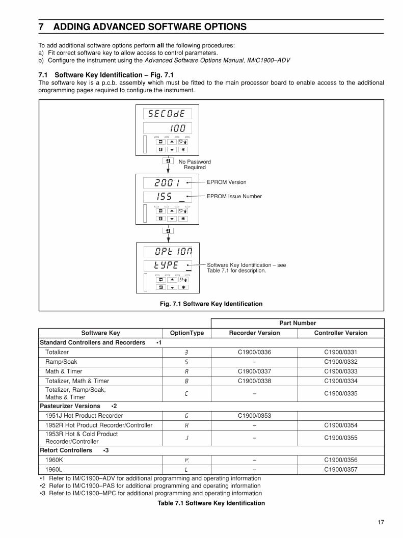
yeKerawtfoS epyTnoitpO noisreVredroceR noisreVrellortnoC
1•sredroceRdnasrellortnoCdradnatS
rezilatoT 3 6330/0091C 1330/0091C
kaoS/pmaR 5 – 2330/0091C
remiT&htaM A 7330/0091C 3330/0091C
remiT&htaM,rezilatoT B 8330/0091C 4330/0091C,kaoS/pmaR,rezilatoT
remiT&shtaM C – 5330/0091C
2•snoisreVreziruetsaP
redroceRtcudorPtoHJ1591 G 3530/0091C
rellortnoC/redroceRtcudorPtoHR2591 H – 4530/0091CtcudorPdloC&toHR3591
rellortnoC/redroceR J – 5530/0091C
3•srellortnoCtroteR
K0691 K – 6530/0091C
L0691 L – 7530/0091CnoitamrofnignitarepodnagnimmargorplanoitiddarofVDA–0091C/MIotrefeR1•noitamrofnignitarepodnagnimmargorplanoitiddarofSAP–0091C/MIotrefeR2•noitamrofnignitarepodnagnimmargorplanoitiddarofCPM–0091C/MIotrefeR3•
To add additional software options perform all the following procedures:a) Fit correct software key to allow access to control parameters.b) Configure the instrument using the Advanced Software Options Manual, IM/C1900–ADV
7.1 Software Key Identification – Fig. 7.1The software key is a p.c.b. assembly which must be fitted to the main processor board to enable access to the additionalprogramming pages required to configure the instrument.
Fig. 7.1 Software Key Identification
Table 7.1 Software Key Identification

18
…7 ADDING ADVANCED SOFTWARE OPTIONS
Identify the software keysockets on main processorboard
UPGRADE KIT
HAS BEEN INSTALLED IN THIS INSTRUMENTWHEN CONTACTING KENT-TAYLOR
REFER TO BOTH INSTRUMENT SERIAL NOAND THIS UPGRADE KIT NO
Fit upgrade label inside the door gasket area
1
2
3
Fit required softwarekey ensuring pins arealigned correctly
7.2 Fitting a Software Key – Fig. 7.2
Warning. Ensure all power supply, any high voltage-operated control circuits and high common voltages areswitched off.
a) Fit the required software key – see Fig. 7.2.
b) Switch on and configure the instrument using Advanced Software Options manual.
Caution. The software key is vulnerable toelectrostatic damage. Handle the board by its edgesonly.
Fig. 7.2 Fitting a Software Key

19
8 COMMISSIONING LEVEL
CPYStd
PAGE
Inpu
t Cal
ibra
tion
Sel
ect I
nput
INPUt
CAL
Sel
ect O
utpu
t
Cal
ibra
te 2
0 m
A
Inpu
t Ass
ignm
ent
Inp
ut
Cal
ibra
tio
nS
ectio
n 8.
6, P
age
26O
utp
ut
Cal
ibra
tio
nS
ectio
n 8.
7, P
age
28C
om
pan
y S
tan
dar
dS
ectio
n 8.
3, P
age
23In
pu
t Ass
igm
ent
Sec
tion
8.4,
Pag
e 24
Pen
Ass
ign
men
tS
ectio
n 8.
5, P
age
25
Cal
ibra
te 1
00m
VC
alib
rate
4 m
A
Out
put C
alib
ratio
nC
ompa
ny S
tand
ard
Set
Co.
Sta
ndar
d
Mai
ns F
ilter
Sec
urity
Typ
e
CPYStd
_ _ _
FILtEr
Hrt
SECUrE
tYPE_
SELECt
______
100MV
CAL–_
CAL
______
OUtPUt
CAL
SELECt
____
CAL
20MA
CAL
4MA
INPUt
ASSIGN
PU.–1
IP–1
Pro
cess
Var
iabl
e 1
PU.–2
IP–2
Pro
cess
Var
iabl
e 2
PU.–3
IP–3
Pro
cess
Var
iabl
e 3
PU.–4
IP–4
Pro
cess
Var
iabl
e 4
PEN
ASSIGN
PEN–1
______
Pen
1 T
ype
INSt
tYPE
Inst
rum
ent
Typ
e P
age
Sec
tion
8.1,
Pag
e 20
& S
ectio
n 8.
2, P
age
22
Inst
rum
ent T
ype
Pg.
Eve
nt O
ptio
n
Dis
play
Opt
ion
tYPE
_______
EV–OPt
___
dIS.OPt
___
Inst
rum
ent T
ype
Cal
ibra
tion
Pas
s
IP–_
____
CJ
Tem
pera
ture
CJtEMP
__._
ASSIGN
UPDAtE
Upd
ate
I/P A
ssig
n.
UPdAtE
____
Upd
ate
Inst
. Typ
e
PEN–2
______
PEN–3
______
PEN–4
______
Pen
2 T
ype
Pen
3 T
ype
Pen
4 T
ype
1–SrCE
____
Pen
1 S
ourc
e
2–SrCE
____
Pen
2 S
ourc
e
3–SrCE
____
Pen
3 S
ourc
e
4–SrCE
____
Pen
4 S
ourc
e
Set
CJ
Tem
pera
ture
SEt CJ
__._
Cal
CJ
Ena
ble
CAL CJ
___
Re-
calib
rate
Ena
ble
rE–CAL
___
Cal
ibra
tion
Pas
s
IP–_
____
Re-
calib
rate
Ena
ble
rE–CAL
___
Cal
ibra
te 1
V
CAL
______
1V C
al E
nabl
e
1VOLt
CAL–_
Pen
Cal
ibra
tio
nS
ectio
n 8.
8, P
age
29
Pen
Cal
ibra
tion
PEN
CAL
PEN–1
HI __
Pen
1 H
igh
Cal
PEN–1
LO __
Pen
1 L
ow C
al
PEN –2
HI __
PEN–2
LO __
PEN–3
HI __
PEN–3
LO __
PEN–4
HI __
PEN–4
LO __
Pen
2 H
igh
Cal
Pen
2 L
ow C
al
Pen
3 H
igh
Cal
Pen
3 L
ow C
al
Pen
4 H
igh
Cal
Pen
4 L
ow C
al
Dis
play
Brig
htne
ss
Dis
pla
y S
et U
pS
ectio
n 8.
9, P
age
30
Dis
play
Set
Up
dISPLY
tESt
brIGht
1___
Rel
ay S
tate
Rel
ay T
est
Sec
tion
8.10
, Pag
e 30
OUtPUt
___
Sel
ect M
odul
e
SELECt
______
Rel
ay T
est
rELAY
tESt
Ope
n I/P
Tes
t
Dig
ital
Inp
ut
Test
Sec
tion
8.11
, Pag
e 31
Inpu
t Tes
t
dIGIP
tESt
OPEN
______
Sel
ect M
odul
e
SELECt
______
Clo
sed
I/P T
est
CLOSE
______
Ou
tpu
t Te
stS
ectio
n 8.
12, P
age
31
Out
put T
est E
nabl
e
tESt
OP ___
OUtPUt
tESt
rSP–1
NONE
Rem
ote
Set
Poi
nt 1
PFb–1
NONE
Pos
ition
FB
1
rSP–2
NONE
Rem
ote
Set
Poi
nt 2
PFb–2
NONE
Pos
ition
FB
2
OPrtOr
LEVEL
bASIC
CONFIG
AdVNCd
CONFIG
CO_SSN
LEVEL
Bas
ic C
onfig
Adv
ance
d C
onfig
Com
mis
ioni
ng L
evel
Ope
rato
r Le
vel
CONtrL
CONFIG
Con
trol
Con
fig
Ava
ilabl
e on
ly o
nC
ontr
olle
r V
ersi
on
Dis
play
Tes
t
8.8.8.8.8.8.
8.8.8.88.8
Dis
play
Brig
htne
ss
Dis
play
Brig
htne
ss
brIGht
2___
brIGht
3___
Inst
rum
ent T
imin
g
Dia
gn
ost
ics
Pag
eS
ectio
n 8.
13, P
age
32
E–tIME
_
Err
or C
ode
ErrOr
______
Dia
gnos
tics
Pag
e
dIAGS
PAGE
Cry
stal
Typ
e
CrYStL
__MEG
LINCHK
______
Line
arity
Che
ck
Sin
gle
or D
ual R
TD
rt––dE
___
Or
All
mod
els
exce
pt C
1950
Pas
teur
izer
Ver
sion
s
C19
50 P
aste
uriz
erV
ersi
ons
Onl
y
Out
put T
est
Pen
Ass
ignm
ent
Cal
100
mV
Ena
ble
Fig. 8.1 Commissioning Level

20
…8 COMMISSIONING LEVEL
INSttYPE
tYPE ____._
EV–OPt
NO YES
8.1 Set Up Instrument Type Page (All Models Except C1950 Series Pasteurizer Versions)
Information.• Select instrument type – controller/recorder, chart type, number of pens and instrument version.• Enable or disable event pen option.• Enable or disable 3rd faceplate (recorder versions 1913 and 1914, controller version 1914 only).
Note.• If fitting a replacement processor board to a controller version, the instrument version must be set before the instrument
type – refer to Section 4.3• For access to the COMMISSIONING LEVEL refer to steps 1 to 3 of Fig. 4.3.
Page Header – Instrument Type
To advance to the Company Standard Page press the switch.
Instrument TypeSelect the instrument type required.
19 x x .xcontroller/recorder chart type:
J ER/C type chart – recorderR ER/C type chart – controllerK PX105 and PXR105 type chart – recorder SeeS PX105 and PXR105 type chart – controllerC Special chart – recorderD Special chart – controller
number of standard pens (1 to 4)
version: 0 non-upgradable version1 recorder version1 or 2 controller version (number of control channels)
Note. Due to variations in pen geometry and position of chart fixings of the instruments,the 5th code letter in the instrument code number (see Section 2 of the Installation Guide) and thechart type selected in this frame must be compatible. For example, an ER/C type chart can onlybe fitted to instruments with J or R in the instrument code number.
Event Option EnableEnable or disable true time event option:
YES – enableNO – disable
Pen 4 can only be used as a true time event marker if the Event Option is enabled and is fitted witha special event arm. The true time event marker operates on the same time line as pen 1.
Note. The true time event option is not available on 4 pen instruments or non-upgradableinstruments.
Continued on next page.
21
8 COMMISSIONING LEVEL…
dIS.OPt
ACtIVE
UPdAtE
NO YES
dONE
UPdAtE
INSt
tYPE
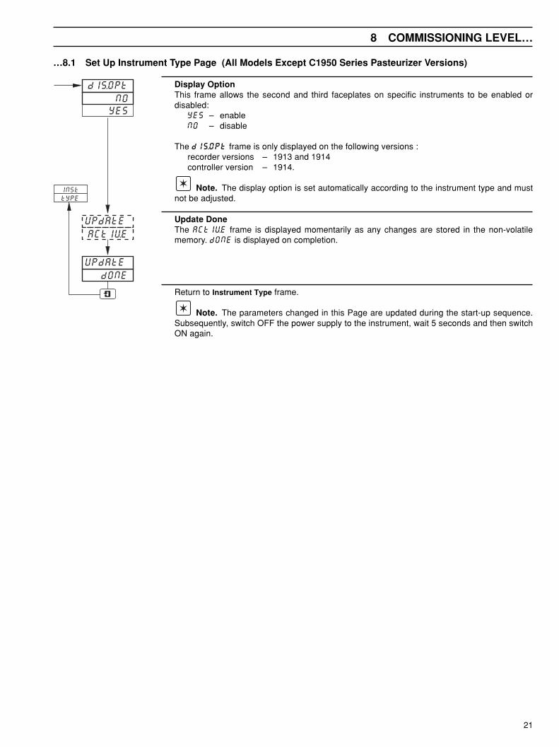
…8.1 Set Up Instrument Type Page (All Models Except C1950 Series Pasteurizer Versions)
Display OptionThis frame allows the second and third faceplates on specific instruments to be enabled ordisabled:
YES – enableNO – disable
The dIS.OPt frame is only displayed on the following versions :recorder versions – 1913 and 1914controller version – 1914.
Note. The display option is set automatically according to the instrument type and mustnot be adjusted.
Update DoneThe ACtIVE frame is displayed momentarily as any changes are stored in the non-volatilememory. dONE is displayed on completion.
Return to Instrument Type frame.
Note. The parameters changed in this Page are updated during the start-up sequence.Subsequently, switch OFF the power supply to the instrument, wait 5 seconds and then switchON again.
22
…8 COMMISIONING LEVEL
INSttYPE
tYPE 1953.r
rt––dE
SINGLE dUAL
ACtIVE
UPdAtE
dONE
UPdAtE
INSt
tYPE
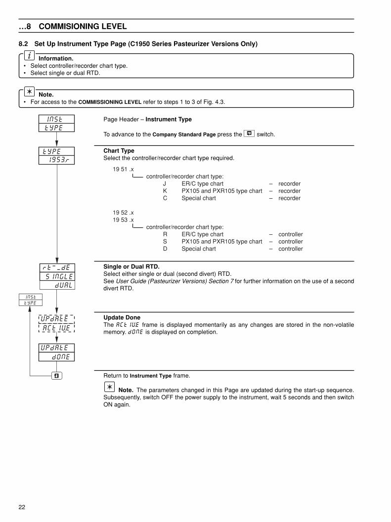
8.2 Set Up Instrument Type Page (C1950 Series Pasteurizer Versions Only)
Information.• Select controller/recorder chart type.• Select single or dual RTD.
Note.• For access to the COMMISSIONING LEVEL refer to steps 1 to 3 of Fig. 4.3.
Page Header – Instrument Type
To advance to the Company Standard Page press the switch.
Chart TypeSelect the controller/recorder chart type required.
19 51 .xcontroller/recorder chart type:
J ER/C type chart – recorderK PX105 and PXR105 type chart – recorderC Special chart – recorder
19 52 .x19 53 .x
controller/recorder chart type:R ER/C type chart – controllerS PX105 and PXR105 type chart – controllerD Special chart – controller
Single or Dual RTD.Select either single or dual (second divert) RTD.See User Guide (Pasteurizer Versions) Section 7 for further information on the use of a seconddivert RTD.
Update DoneThe ACtIVE frame is displayed momentarily as any changes are stored in the non-volatilememory. dONE is displayed on completion.
Return to Instrument Type frame.
Note. The parameters changed in this Page are updated during the start-up sequence.Subsequently, switch OFF the power supply to the instrument, wait 5 seconds and then switchON again.
23
8 COMMISSIONING LEVEL…
CPYStdPAGE
CPYStd
YES
FILtEr
SECUrE
60 Hrt
tYPE A
dONE
NO
50 Hrt
CPYStdACtIVE
NO
tYPE b
CrYStL
8MEG 12MEG
CPYStd
CPYStd
PAGE
S o f t w a r eve r s i o n 2 1 0 1i s s u e 1 o rl a t e r i n u s e
CPYStd
PAGE
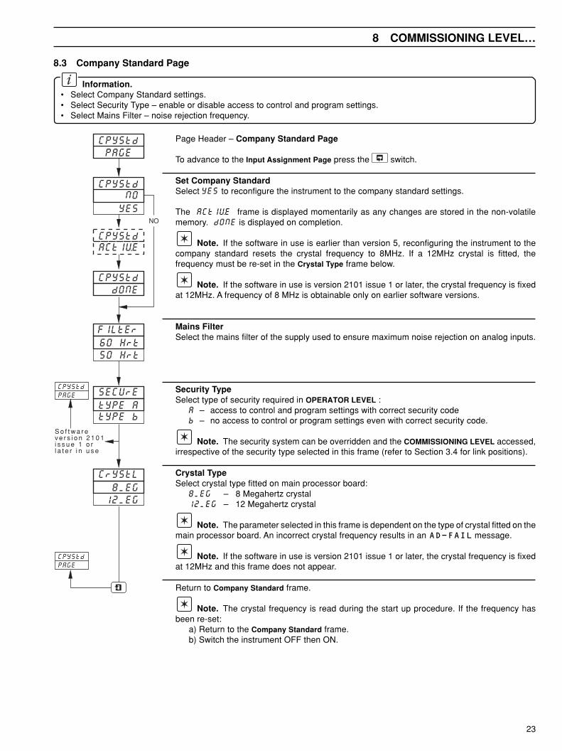
8.3 Company Standard Page
Information.• Select Company Standard settings.• Select Security Type – enable or disable access to control and program settings.• Select Mains Filter – noise rejection frequency.
Page Header – Company Standard Page
To advance to the Input Assignment Page press the switch.
Set Company StandardSelect YES to reconfigure the instrument to the company standard settings.
The ACtIVE frame is displayed momentarily as any changes are stored in the non-volatilememory. dONE is displayed on completion.
Note. If the software in use is earlier than version 5, reconfiguring the instrument to thecompany standard resets the crystal frequency to 8MHz. If a 12MHz crystal is fitted, thefrequency must be re-set in the Crystal Type frame below.
Note. If the software in use is version 2101 issue 1 or later, the crystal frequency is fixedat 12MHz. A frequency of 8 MHz is obtainable only on earlier software versions.
Mains FilterSelect the mains filter of the supply used to ensure maximum noise rejection on analog inputs.
Security TypeSelect type of security required in OPERATOR LEVEL :
A – access to control and program settings with correct security codeb – no access to control or program settings even with correct security code.
Note. The security system can be overridden and the COMMISSIONING LEVEL accessed,irrespective of the security type selected in this frame (refer to Section 3.4 for link positions).
Crystal TypeSelect crystal type fitted on main processor board:
8MEG – 8 Megahertz crystal12MEG – 12 Megahertz crystal
Note. The parameter selected in this frame is dependent on the type of crystal fitted on themain processor board. An incorrect crystal frequency results in an AD-FAIL message.
Note. If the software in use is version 2101 issue 1 or later, the crystal frequency is fixedat 12MHz and this frame does not appear.
Return to Company Standard frame.
Note. The crystal frequency is read during the start up procedure. If the frequency hasbeen re-set:
a) Return to the Company Standard frame.b) Switch the instrument OFF then ON.
24
…8 COMMISSIONING LEVEL
Single PenInstrument
INPUt
ASSIGN
INPUtASSIGN
PV–1 IP–1
PV–2
IP–1 IP–2 IP–3 IP–4 IP–5 IP–6
bLK–1 bLK–2 bLK–3 bLK–4
PV–3
PV–4
rSP–1
PFb-1
rSP–2
PFb–2
2 PenInst.
3 PenInst.
2, 3 and 4 PenInstrument
3 and 4 Pen Instrument
4 Pen Instrument
UPdAtE dONE
UPdAtEACtIVE
SingleControllerInstrument
2 ControllerInstrument
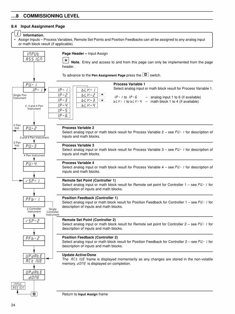
8.4 Input Assignment Page
Information.• Assign Inputs – Process Variables, Remote Set Points and Position Feedbacks can all be assigned to any analog input
or math block result (if applicable).
Page Header – Input Assign
Note. Entry and access to and from this page can only be implemented from the pageheader.
To advance to the Pen Assignment Page press the switch.
Process Variable 1Select analog input or math block result for Process Variable 1.
IP-1 to IP-6 – analog input 1 to 6 (if available)bLK-1 to bLK-4 – math block 1 to 4 (if available)
Process Variable 2Select analog input or math block result for Process Variable 2 – see PV-1 for description ofinputs and math blocks.
Process Variable 3Select analog input or math block result for Process Variable 3 – see PV-1 for description ofinputs and math blocks.
Process Variable 4Select analog input or math block result for Process Variable 4 – see PV-1 for description ofinputs and math blocks.
Remote Set Point (Controller 1)Select analog input or math block result for Remote set point for Controller 1 – see PV-1 fordescription of inputs and math blocks.
Position Feedback (Controller 1)Select analog input or math block result for Position Feedback for Controller 1 – see PV-1 fordescription of inputs and math blocks.
Remote Set Point (Controller 2)Select analog input or math block result for Remote set point for Controller 2 – see PV-1 fordescription of inputs and math blocks.
Position Feedback (Controller 2)Select analog input or math block result for Position Feedback for Controller 2 – see PV-1 fordescription of inputs and math blocks.
Update Active/DoneThe ACtIVE frame is displayed momentarily as any changes are stored in the non-volatilememory. dONE is displayed on completion.
Return to Input Assign frame
25
8 COMMISSIONING LEVEL…
PENASSIGN
PEN-1
trENd
EVENt
1-SrcE OP-2 OP-1 PV-4 PV-3PFB-2
SP-2 PV-2PFB-1
SP-1 PV-1
PEN-2
trENd
EVENt
2-SrcE ____
PEN
ASSIGN
PEN-3
trENd
EVENt
3-SrcE ____
PEN-4
trENd
EVENt
4-SrcE ____
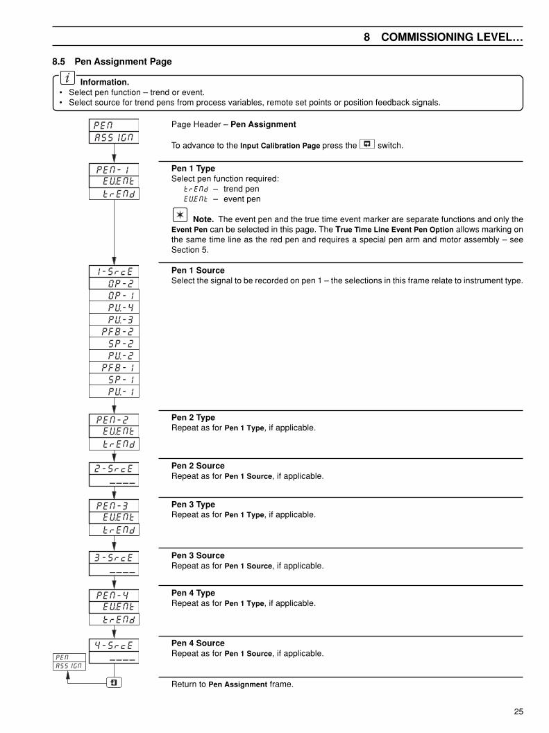
Page Header – Pen Assignment
To advance to the Input Calibration Page press the switch.
Pen 1 TypeSelect pen function required:
trENd – trend penEVENt – event pen
Note. The event pen and the true time event marker are separate functions and only theEvent Pen can be selected in this page. The True Time Line Event Pen Option allows marking onthe same time line as the red pen and requires a special pen arm and motor assembly – seeSection 5.
Pen 1 SourceSelect the signal to be recorded on pen 1 – the selections in this frame relate to instrument type.
Pen 2 TypeRepeat as for Pen 1 Type, if applicable.
Pen 2 SourceRepeat as for Pen 1 Source, if applicable.
Pen 3 TypeRepeat as for Pen 1 Type, if applicable.
Pen 3 SourceRepeat as for Pen 1 Source, if applicable.
Pen 4 TypeRepeat as for Pen 1 Type, if applicable.
Pen 4 SourceRepeat as for Pen 1 Source, if applicable.
Return to Pen Assignment frame.
8.5 Pen Assignment Page
Information.• Select pen function – trend or event.• Select source for trend pens from process variables, remote set points or position feedback signals.

26
…8 COMMISSIONING LEVEL
INPUt CAL
SELECt ____
100MV
CAL –NCAL –Y
______CAL
___._IP-x
FAIL
CAL
NO
rE-CAL YES
dONE
CAL
NO
FAILPASS
YES
8.6 Input Calibration Page
Information.• Low range calibration (100mV).• High range calibration (1V).• Cold junction compensation calibration.
The following equipment is required to carry out input calibration:DC Voltage Calibrator – accuracy of 1V and 100mV range (± 0.05% of setting).
Thermometer – accuracy of ± 0.1°C.
Note.• Do not perform the input calibration procedures if the d.c. voltage calibrator or thermometer have not been calibrated.• Take note of the link positions before carrying out the 100mV, 1V and Cold Junction calibration procedures.
Page Header – Input Calibration
To advance to the Output Calibration Page press the switch.
Select InputSelect input required.
Calibrate 100mV EnableIf 100mV calibration is required, set the input links to mV – see Section 4 of Installation Guide.
Connect a d.c. voltage calibrator to the selected input and apply 100mV.
Select CAL-Y to enable 100mV calibration.
If 100mV calibration is not required select CAL–N.
Calibrate 100mVIf calibrate 100mV is enabled, (–) is displayed in the lower display during calibration. dONE isdisplayed on completion.
Calibration PassIf calibration is successful, the selected input displayed on the upper display and the input valuedisplayed on the lower display.
Calibration FailCalibration failure may be due to the following:
incorrect input link settingincorrect input signal appliedfaulty non-volatile memory.
Re-calibration EnableEnable or disable 100mV re-calibration:
YES – repeat 100mV calibrationNO – advance to the next frame.
Continued on next page.

27
8 COMMISSIONING LEVEL…
CAL CJ NO
SEt CJ __._
CJtEMP
YES
__._
SELECt ____ NO
YES
1VOLtCAL –NCAL –Y
______CAL
___._IP-x
FAILCAL
NO
rE-CAL YES
dONECAL
NO
FAILPASS
YES
…8.6 Input Calibration Page
Calibrate 1V EnableIf 1V calibration is required, set the input links to V – see Section 4 of Installation Guide.
Connect a d.c. voltage calibrator to the selected input and apply 1V.
Select CAL-Y to enable 1V calibration.
If 1V calibration is not required select CAL–N.
Calibrate 1VIf calibrate 1V is enabled, (–) is displayed in lower display during calibration. dONE is displayedon completion.
Calibration PassIf calibration is successful, the selected input is displayed on the upper display and input value isdisplayed on the lower display.
Calibration FailCalibration failure may be due to the following:
incorrect input link settingincorrect input signal appliedfaulty non-volatile memory.
Re-calibration EnableEnable or disable 1V re-calibration:
YES – repeat 1V calibrationNO – advance to the next frame.
Calibrate Cold JunctionAn automatic cold junction (ACJC) transistor (TR10) is fitted on the main p.c.b. adjacent tomodule position 1.
If cold junction calibration is required, set the input links to mV – see Section 4 of InstallationGuide.
Select YES to enable cold junction calibration.
If cold junction calibration is not required select NO.
Set Cold Junction TemperatureMeasure the temperature adjacent to the automatic cold junction transistor (TR10). Set themeasured temperature in °C.
If the input links are set incorrectly Check Links flashes until the links are reset.
Cold Junction TemperatureCheck cold junction temperature is the same as the value set in the SEt CJ frame above.
Note. If the cold junction temperature is different from the value set in the SEt CJ frameabove, reset the cold junction temperature.
Return to Select Input frame.
Note. Reset the links to their original positions before proceeding to the next Page.

28
…8 COMMISSIONING LEVEL
OUtPUt CAL
SELECt ____
CAL
20MA
CAL
4MA
SELECt ____
8.7 Output Calibration Page
Information.• 20mA Calibration.• 4mA Calibration.
The following equipment is required to carry out input calibration:Digital Voltmeter – accuracy 0.02% of reading.
100Ω Resistance Standard – accuracy ±0.01%
Note. Do not perform the output calibration procedures if the digital voltmeter has not been calibrated.
Caution. The main input and current output calibration data (unique to each instrument) is contained in the non-volatile memory ICs 24 and 25. Do not interchange these ICs between instruments.
Page Header – Output Calibration
To advance to the Pen Calibration Page press the switch.
Select OutputSelect output required.
Connect the 100Ω resistance standard across the output that requires calibration and connectthe digital voltmeter across the resistor.
Calibrate 20mAUse the and switches to set the output reading on the digital voltmeter to 2.0V.
Calibrate 4mAUse the and switches to set the output reading on the digital voltmeter to 0.4V.
Return to Select Output frame.
29
8 COMMISSIONING LEVEL…
PENCAL
PEN 1
ACtIVE
LINCHK
dONE
LINCHK
PEN 1
PEN x
PEN x
PEN
CAL
LO ___
LO ___
HI __
HI __
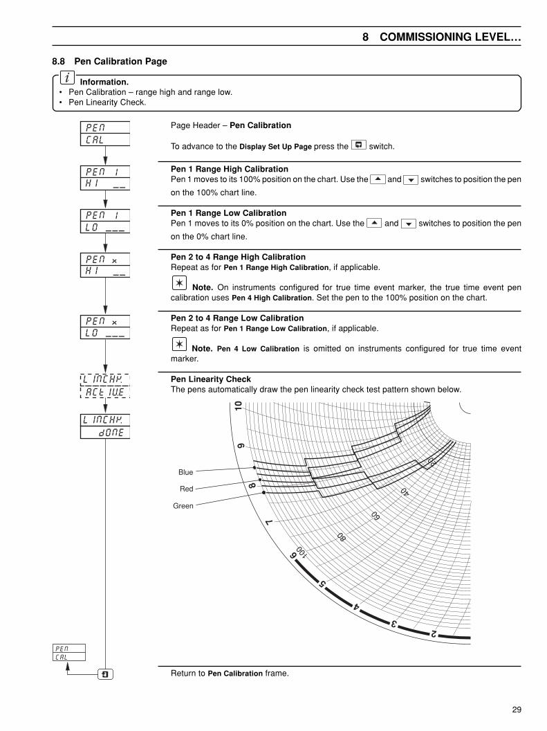
8.8 Pen Calibration Page
Information.• Pen Calibration – range high and range low.• Pen Linearity Check.
Page Header – Pen Calibration
To advance to the Display Set Up Page press the switch.
Pen 1 Range High CalibrationPen 1 moves to its 100% position on the chart. Use the and switches to position the pen
on the 100% chart line.
Pen 1 Range Low CalibrationPen 1 moves to its 0% position on the chart. Use the and switches to position the pen
on the 0% chart line.
Pen 2 to 4 Range High CalibrationRepeat as for Pen 1 Range High Calibration, if applicable.
Note. On instruments configured for true time event marker, the true time event pencalibration uses Pen 4 High Calibration. Set the pen to the 100% position on the chart.
Pen 2 to 4 Range Low CalibrationRepeat as for Pen 1 Range Low Calibration, if applicable.
Note. Pen 4 Low Calibration is omitted on instruments configured for true time eventmarker.
Pen Linearity CheckThe pens automatically draw the pen linearity check test pattern shown below.
Red
Green
Blue
4
32
6
7
89
10
100
80
60
40
20
5
Return to Pen Calibration frame.

30
…8 COMMISSIONING LEVEL
dISPLY tESt
brIGHt
8.8.8.8.8.8.
8.8.8.8.8.8.
brIGHt
brIGHt
dISPLY
tESt
__1
__2
__3
rELAY tESt
SELECtPOSN 1
POSN 6 NONE
NONE
OUtPUt
ON OFF
8.9 Display Set Up Page
Information.• Display Brightness – illuminates all display segments, bar graph segments (if applicable) and l.e.d.s.• Display Brightness.
Page Header – Display Test
To advance to the Relay Test Page press the switch.
Display 1 BrightnessSet brightness required for display 1 (4 to 15). The higher the value the brighter the display.
Display 2 BrightnessSet brightness required for display 2 (if fitted).
Display 3 BrightnessSet brightness required for display 3 (if fitted).
Display TestThe display test alternate between ‘8.8.8.8.8.8.’ on the upper display, ‘8.8.8.8.8.8.’ on the lowerdisplay, the l.e.d. indication and bar graph displays of each faceplate fitted.
Ensure all segments in the upper and lower displays, all l.e.d. indications and bar graph displaysare illuminated.
Return to Display Test frame.
8.10 Relay Test Page
Information.• Relay Test.
Page Header – Relay Test
To advance to the Digital Input Test Page press the switch.
Select Module PositionThe selections in this frame relate to modules fitted. Select module position required,
Select Output StateSelect the relay output state for the module selected in the previous frame:
Note. All relays on the selected module are turned ON or OFF together.
Return to Select Module Position frame.
31
8 COMMISSIONING LEVEL…
dIG IP tESt
OPEN PASS
SELECt
POSN 1POSN 2POSN 3POSN 4 NONE
FAIL
CLOSE PASS
FAIL
NONE
OUtPUt tESt
OP ON tESt
OP OFF
OPtESt
ACtIVE
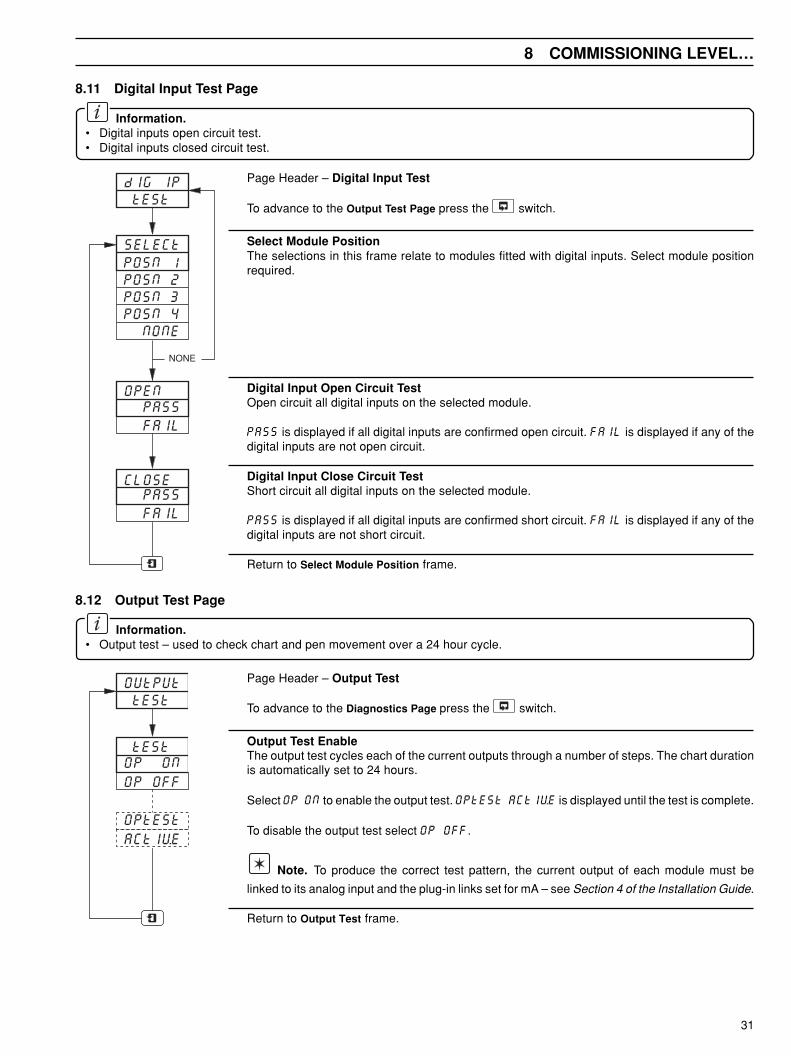
8.11 Digital Input Test Page
Information.• Digital inputs open circuit test.• Digital inputs closed circuit test.
Page Header – Digital Input Test
To advance to the Output Test Page press the switch.
Select Module PositionThe selections in this frame relate to modules fitted with digital inputs. Select module positionrequired.
Digital Input Open Circuit TestOpen circuit all digital inputs on the selected module.
PASS is displayed if all digital inputs are confirmed open circuit. FAIL is displayed if any of thedigital inputs are not open circuit.
Digital Input Close Circuit TestShort circuit all digital inputs on the selected module.
PASS is displayed if all digital inputs are confirmed short circuit. FAIL is displayed if any of thedigital inputs are not short circuit.
Return to Select Module Position frame.
8.12 Output Test Page
Information.• Output test – used to check chart and pen movement over a 24 hour cycle.
Page Header – Output Test
To advance to the Diagnostics Page press the switch.
Output Test EnableThe output test cycles each of the current outputs through a number of steps. The chart durationis automatically set to 24 hours.
Select OP ON to enable the output test. OPtESt ACtIVE is displayed until the test is complete.
To disable the output test select OP OFF.
Note. To produce the correct test pattern, the current output of each module must be
linked to its analog input and the plug-in links set for mA – see Section 4 of the Installation Guide.
Return to Output Test frame.

32
…8 COMMISSIONING LEVEL
Green
Red
Output Test Pattern
dIAGS PAGE
ErrOr 0
E-tIME __
…8.12 Output Test PageThe output test can be used to check the chart and pen movement and detect any linearity or hysteresis errors in pen positioning.
8.13 Diagnostics Page
Information.• Instrument timing.
Page Header – Diagnostics Page
To advance to the COMMISSIONING LEVEL frame press the switch.
Error CodeThis frame is for factory use only.
Instrument TimingThe display indicates the number of 8ms interrups used to process the enabled functions.
The total executive cycle time is 240ms.
Example – a display of 20 indicates 160ms of the executive cycle time have been used to processthe enabled functions.
Return to Diagnostics Page frame.

33
9 INSTRUMENT REPAIR
9.1 Non-volatile Memory ICs
Caution. The main input and current output calibration data (unique to each instrument) is contained in the non-volatile memory ICs 24 and 25. Do not substitute between instruments or each other. If for any reason these ICs are replacedthen both the main input and the current output will require recalibration – see sections 8.5 and 8.6.
9.2 Microprocessor Board Replacement
Caution. Replacement microprocessor boards are despatched from the manufacturing unit with Company Standardsettings. Before replacing a microprocessor board, make a note of all non-standard or instrument-specific configuration data.When mechanical installation is complete and the instrument has powered up successfully, carry out the configurationprocedure as detailed in Sections 8.1 to 8.12.

IM/C
1900
–AG
NIs
sue
7
The Company’s policy is one of continuous productimprovement and the right is reserved to modify the informationcontained herein without notice.
© ABB 2001 Printed in UK (04.01)
ABB Automation LtdHoward Road, St. NeotsCambridgeshire, PE19 8EUUKTel: +44 (0)1480-475-321Fax: +44 (0)1480-217-948
ABB Automation Inc.125 E. County Line RoadWarminster, PA 18974USATel: +1 215-674-6000Fax: +1 215-674-7183
ABB has Sales & Customer Support expertisein over 100 countries worldwide
www.abb.com