commercial comfort system (ccs) product bulletincgproducts.johnsoncontrols.com/met_pdf/12011347.pdf4...
TRANSCRIPT

Refer to the QuickLIT Web site for the most up-to-date version of this document.
Commercial Comfort System (CCS)Product Bulletin
Code No. LIT-12011347Issued June 16, 2015
The Commercial Comfort System (CCS) improves occupant comfort by providing reliable zoning control of standard Johnson Controls® Rooftop Units (RTUs), including split system and heat pump equipment. CCS applications include single zone, Change-Over Bypass (COBP), and Variable Air Volume (VAV) zoning systems. The innovative control algorithms provide superior temperature control of Heating, Ventilating, and Air Conditioning (HVAC) equipment.
Advanced operating modes, such as load shed, power exhaust, Demand Controlled Ventilation (DCV), and occupancy sensing, ensure the Commercial Comfort System is the most advanced Building Automation System (BAS) for the light commercial market.
The CCS features advanced Direct Digital Control (DDC) controllers bundled with Johnson Controls Single Packaged Units (SPUs), actuators, sensors, and damper assemblies. Optional accessories include Input/Output Module (IOM) controllers and thermostat controllers. All devices are self-configuring and monitored by the System Manager and Zone Coordinator supervisory controllers. These supervisory controllers feature an intuitive color touchscreen for interfacing with the entire building providing the ability to schedule, trend, and adjust parameters.
Figure 1: CCS Zoning Application
Table 1: Features and Benefits
Features Benefits
Innovative Touchscreen User Interface (UI) Provides a simple centralized interface without the need for additional hardware.
Factory Mounted and Wired Equipment Assemblies
Save installation time and cost with pre-assembled and pre-configured controller and actuator systems.
Adjustable Logic Parameters Optimize HVAC zone control of a system.
Advanced DDC Zone Controllers withAuto-Tuning Capability
Provide reliable zone control with minimal commissioning time.
Factory Loaded and Self-Configuring Components
Eliminate software commissioning tools, which reduces installation time and cost.
IOM Controller Offering Increases Input and Output (I/O) field points and provides interlocking capabilities for expanded operation.
Advanced Operating Modes Provide for greater capabilities, such as load shed for energy savings, Demand Controlled Ventilation (DCV) for CO2 level monitoring, and standby mode for occupancy sensing.
Commercial Comfort System (CCS) Product Bulletin 1

CCS NetworkThe CCS control network contains a supervisory controller, Universal SPU, VAV boxes, zone damper assemblies, zone sensors, and bypass damper assemblies. Figure 2 shows an example of the CCS network.
Supervisory ControllersThe supervisory controllers consist of a System Manager (SM) and/or Zone Coordinator (ZC). The supervisory controllers feature an intuitive color touchscreen for interfacing with the entire building providing the ability to schedule, trend, and adjust parameters. The supervisory controllers have predefined point lists for the appropriate mechanical equipment configuration used within the facility. The ZC also contains zone voting logic that reads individual
zone requirements and places the rooftop unit into the required heating or cooling mode. You can access the supervisory controller with a remote user interface via a standard Web browser on any computer connected to the building network.
Figure 2: CCS Network
Smart EquipmentControl (SEC) Unit
Setup for CV Operationon CVSZ RTU
Control Board (UCB)
Smart EquipmentControl (SEC) UnitControl Board (UCB)Setup for VAV Operationon VAV RTU
Zone Coordinatorwith Display
(Changeover Bypass)
System Manager
VAV Box Controller
Input/Output Module (IOM)
Zone Bus(MS/TP)
Sensor-Actuator(SA) Bus
System Bus (MS/TP)
Bypass Controller
Zone Sensors
TCP/IP Ethernet
LC-SMU-0
Thursday, May 8, 2008 5:23:44 PM
Outdoor Air Temperature: 63.1 Deg F
Software Revision: 1.0.2445
LC-ZCU-10
Thursday, May 8, 2008 5:23:44 PM
Software Revision: 1.0.2445
Zoning System Status:
Outdoor Air Temperature:
Off
68.3 Deg F
Smart Equipment Control (SEC)Setup for CV Operation on Changeover BypassRooftop Controller Unit
(CV RTU)
Zone Coordinatorwithout Display (VAV)
Zone Controllers
VAV BoxControllers
VAV BoxControllers
Zone Sensors
Zone Sensors
Zone Sensor
Zone Controller with Supplemental Heat
Zone Sensor
TEC260x-4 Thermostat Controller
Commercial Comfort System (CCS) Product Bulletin2

System Manager
The System Manager (SM) brings an entirely new generation of Building Automation System (BAS) technology to light commercial systems. The SM is a building level controller that manages facilities using Internet and Information Technology (IT). The SM supports a comprehensive set of supervisory features and functions for small commercial facilities. A single SM within a building provides monitoring and control, alarm, trending, management, scheduling, and simple data storage.
The SM has an embedded color touchscreen user interface and also supports connected Web browsers for remote monitoring. The SM provides e-mail alarm messages through the onboard Ethernet connection or optional modem.
As a key component of the Johnson Controls® Commercial Comfort System (CCS), the SM supports up to 38 devices on the System Manager bus, including 10 Zone Coordinators, 24 SPU controllers and/or TEC260x-4 Series Thermostat Controllers, and 4 IOMs.
Features
• color touchscreen user interface
• remote browser-based user interface
• supervision of Johnson Controls equipment controller networks
• multiple connection options for data access via a standard Ethernet Transmission Control Protocol/Internet Protocol (TCP/IP) or serial interface with optional modem
• ability to integrate TECs and IOMs allows for advanced operating modes and functions, such as standby for energy savings, and IOM point interlocking
The SM software is specifically designed to meet the needs of building owners and managers to efficiently monitor and control all the mechanical and electrical systems in a typical building, such as:
• Johnson Controls Series 5, Series 10, Series 20, Series 40, and Series 100 (50 to 60 ton only) single packaged units
• zoning systems using the Zone Coordinator (ZC)
• other mechanical and electrical equipment using the Input/Output Module (IOM)
• third-party single packaged units using the Universal Single Packaged (SPU) controller
The SM monitors equipment by collecting data from the field control devices, then coordinating the required commands and sending them to the equipment at the required priority.
Figure 3: CCS System Manager
Commercial Comfort System (CCS) Product Bulletin 3

Zone Coordinator
The ZC is a system level controller that manages HVAC zoning systems in smaller facilities using Internet and Information Technology (IT). The ZC uses a Master-Slave/Token-Passing (MS/TP) communication bus, called the Zone Bus, to communicate with Johnson Controls terminal devices. These devices include CCS zone and bypass damper assemblies; CCS VAV terminal units; and Johnson Controls Series 5, Series 10, Series 20, Series 40, and Series 100 (50 to 60 ton only) single packaged units. The ZC self configures based on the controllers connected to the Zone Bus.
The ZC supports a comprehensive set of supervisory features and functions for small commercial facilities with no field programming required. A single ZC within a building provides monitoring and control, alarm, trending, management, scheduling, and simple data storage for a simple zoning system. In facilities with multiple zoning systems, multiple zone coordinators can be networked with a System Manager (SM) to provide coordinated BAS functions.
The ZC has an optional color touchscreen user interface and also supports connected Web browsers for remote monitoring. It provides provisions for e-mail alarm messaging through the onboard Ethernet connection or optional modem.
As a key component of the Johnson Controls® Commercial Comfort System (CCS), the ZC supports up to 26 devices on a Zone Coordinator bus for a Change-Over Bypass (COBP) system, or up to 33 devices on a Zone Coordinator bus for a Variable Air Volume (VAV) system.
Features
• optional color touchscreen user interface for stand-alone zoning systems
• remote browser-based user interface
• supervision and control of Johnson Controls single packaged units and CCS terminal devices
• multiple connection options for data access via a standard Ethernet TCP/IP or serial interface with optional modem
The ZC is specifically designed to meet the needs of building owners and managers to efficiently monitor and control all the mechanical and electrical systems in a typical building such as:
• Johnson Controls Series 5, Series 10, Series 20, Series 40, and Series 100 (50 to 60 ton only) single packaged units
• CCS zone and bypass damper controllers
• CCS Variable Air Volume (VAV) controllers
The ZC monitors zone heating and cooling demand by collecting data from the zone terminal devices. The ZC then determines the mode of operation for the single packaged unit and commands it appropriately.
Johnson Controls Rooftop UnitsThe factory-mounted Smart Equipment rooftop controller features control of heating, cooling, and economizer functions.
Variable Air Volume (VAV) AssembliesThe VAV assembly is a zone control and pressure control device which includes a VAV zone box. The VAV zone box can be configured in several assembled options directly at the factory. The VAV zone box sizes range from 6 to 16 in. (15 to 41 cm) and feature both fan powered parallel or series fans with electric staged or hot water heating.
The VAV zone box damper modulates in response to both user and control-defined setpoints regarding space temperature and flow variations.
Features
• factory-mounted and wired control components reduce installation time
• fast response actuator drives the damper from full open to full close (90°) in 60 seconds to reduce the commissioning time
• continuous loop tuning provided by Pattern Recognition Adaptive Control (PRAC) technology
Figure 4: CCS Zone Coordinator
Commercial Comfort System (CCS) Product Bulletin4

Zone/Bypass Damper AssembliesThe zone and bypass dampers are zone control and pressure control devices that include the damper and control components in a factory assembled configuration. The assembly includes the round or rectangular damper, configured Direct Digital Control (DDC) controller, electric actuator, and pressure sensor (in the bypass damper only), National Electrical Manufacturers' Association (NEMA) Type 1 enclosure, and optional power transformer. The controllers are application specific, factory programmed digital controllers that communicate via the BACnet® MS/TP protocol. Both the zone and bypass controllers operate as part of a larger zoning system and provide zone and pressure control for the appropriate mechanical equipment.
The zone damper modulates in response to temperature variations relative to a user defined space temperature setpoint. The bypass damper modulates to maintain supply duct static pressure setpoint.
Features
• factory mounted and wired control components reduce installation time
• fast response actuator drives the damper from full open to full close (90°) in 60 seconds to reduce commissioning time
• continuous loop tuning provided by Pattern Recognition Adaptive Control (PRAC) technologies
• available in both round and rectangular configurations
• supplemental heat for both staged and modulated damper assemblies
Round Damper AssembliesThe round damper assemblies feature superior design, solid molded damper shafts, and control enclosures. The round damper assembly features both staged and modulated supplement heat options.
Superior Design
The round zone damper is a 22-gauge round unit. An automated manufacturing process produces damper blades to exact specifications. The dampers are designed for low noise operation with minimal friction loss and a tight closure seal. Air valve leakage is less than 1% of rated capacity at 3 in. wg inlet pressure.
Solid Molded Damper Shaft
The solid damper shaft is molded using a high-impact, high-strength composite material. It is designed to eliminate condensation on the extended portion that penetrates the unit casing. The shaft allows a more secure attachment to the damper actuator, since the set screws adhere to this material better than they do metal. The high impact material gives the shaft superior impact strain resistance compared to cast metal shafts. The damper blade is mounted on the damper shaft and connected by means of an integral molded sleeve. The shaft rotates in low friction, self-lubricating bearings.
Control Enclosure
The zone and bypass damper assembly include a NEMA Type 1 galvanized steel (22 gauge) enclosure for factory mounting of the direct digital controller, damper actuator, differential pressure sensor (in bypass damper only), and an optional multi-tap primary/24 VAC secondary transformer.
Rectangular Damper Assemblies
Superior Design
The rectangular damper offers sturdy, steel construction with interlocking frame design. The unit frame is constructed of 5 x 1 in. (127 x 25 mm) 16-gauge galvanized steel hat channel reinforced with corner braces for structural strength equal to 13 gauge (2.28 mm). For dampers under 13 in. (330 mm), low profile 3-1/2 x 3/8 in. (89 x 10 mm) 16-gauge galvanized steel channels are located on the top and bottom frame. The damper locks together without bolts, screws, or rivets that could shake loose. The frame corners are internally braced to reduce racking.
Damper Blades
Blades are 6 in. (152 mm) wide, 16 gauge (1.6 mm) galvanized steel approximately 6 in. (152 mm) on center with parallel action.
Damper Shaft
The 1/2-inch (13 mm) plated steel hex axles positively lock to blades without screws or welds. Non-stick, non-corrosive bearings assure long life and ease of operation. Axles and bearings combine with a shake proof linkage for low maintenance operation.
Commercial Comfort System (CCS) Product Bulletin 5

6
Figure 5 shows the round damper assembly dimensions. Figure 6 shows the rectangular damper assembly dimensions. Additional rectangular damper sizes are available through special order.
Table 2: Round Damper Assembly Construction Components
Damper Part Construction Component
Frame 22 gauge galvanized steel valve body with embossed beads. Withstands 125 per hour salt spray test per ASTM B-117.
Blade Full circular closed cell gasket secured between two pieces of 22 gauge sheet metal.
Damper Shaft Molded solid damper shaft constructed of high-impact, high-strength composite material.
Bearing Low friction self-lubricating bearings
Seal Full circular closed cell gasket
Temp Limits 32 to 122°F (0 to 50°C)
Table 3: Round Damper Assemblies Selection Chart
Damper Size(Area - Sq Ft)
6 inch (0.188)
8 inch(0.338)
10 inch(0.532)
12 inch(0.769)
14 inch(1.05)
16 inch(1.375)
Air Velocity Through Damper (FPM)
Zone Damper Airflow - CFM
750 FPM - Zone 141 254 399 577 788 1,031
1,000 FPM - Zone 188 338 532 769 1,050 1,375
1,250 FPM - Zone 235 423 665 961 1,313 1,718
1,500 FPM - Bypass only 282 507 798 1,154 1,575 2,062
1,750 FPM - Bypass only 329 592 931 1,346 1,838 2,405
2,000 FPM - Bypass only 376 676 1,064 1,538 2,100 2,749
2,250 FPM - Bypass only 423 761 1,197 1,730 2,363 3,094
Airflow
Top View
Standard ControlMounting Plate
Airflow
Side View Inlet End ViewSize 10 Shown
6.00
Control Enclosure Standard
Unit Size 06 08 10 12 14 16 Dimension - D 5.88” 7.88” 9.88” 11.88” 13.88” 15.88”
Figure 5: Round Damper Assembly Dimensions
Commercial Comfort System (CCS) Product Bulletin

Table 4: Rectangular Damper Assembly Construction Components
Damper Part Construction Component
Frame 5 x 1 x 16 inch gauge galvanized steel hat channel reinforced with corner braces for structural strength equal to 13 gauge.
Blade 6 inches wide, 16 gauge galvanized steel approximately 6 inches on center, parallel action
Damper Shaft 1/2 inch plated steel hex axles
Bearing Corrosion resistant, molded synthetic sleeve type
Temp Limits 32 to 122°F (0 to 50°C)
8"x12"8"x14"8"x16"10"x16"10"x20"14"x18"
Zone Damper Size AxB
14"x12"16"x16"20"x20"30"x30"
Bypass Damper Size AxB
Figure 6: Rectangular Damper Assembly Dimensions
Commercial Comfort System (CCS) Product Bulletin7
Zone Damper AssembliesFigure 7 shows a CCS Zone Damper Assembly.
The advanced DDC controller modulates the zone damper. The controller reads zone temperature sensor information and modulates the zone damper to adequately heat or cool the area. Damper parameters can be modified from default settings through the SM or ZC. Information at the controller level can be viewed through the touchscreen user interface at the supervisory controller or remotely via a computer with an Internet browser.
Bypass Damper AssemblyFigure 8 shows a bypass damper assembly.
The bypass damper regulates static pressure through the system. As building load is satisfied, and the zone dampers in the system begin to modulate closed, static pressure increases in the duct work. As system static pressure rises above the setpoint, the DDC controller modulates the bypass damper open, allowing excess airflow from the supply side to the return side of the single packaged unit. This scenario eliminates excessive system static pressure, prevents the generation of noise at the diffusers, and prevents the loss of temperature control in the zones.
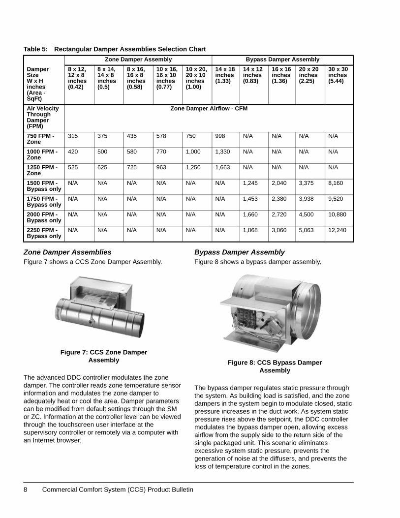
Table 5: Rectangular Damper Assemblies Selection Chart
Zone Damper Assembly Bypass Damper Assembly
Damper Size W x H inches(Area - SqFt)
8 x 12, 12 x 8 inches(0.42)
8 x 14, 14 x 8 inches(0.5)
8 x 16, 16 x 8 inches(0.58)
10 x 16,16 x 10 inches(0.77)
10 x 20, 20 x 10 inches(1.00)
14 x 18 inches(1.33)
14 x 12 inches (0.83)
16 x 16 inches(1.36)
20 x 20 inches(2.25)
30 x 30 inches(5.44)
Air Velocity Through Damper (FPM)
Zone Damper Airflow - CFM
750 FPM - Zone
315 375 435 578 750 998 N/A N/A N/A N/A
1000 FPM - Zone
420 500 580 770 1,000 1,330 N/A N/A N/A N/A
1250 FPM - Zone
525 625 725 963 1,250 1,663 N/A N/A N/A N/A
1500 FPM - Bypass only
N/A N/A N/A N/A N/A N/A 1,245 2,040 3,375 8,160
1750 FPM - Bypass only
N/A N/A N/A N/A N/A N/A 1,453 2,380 3,938 9,520
2000 FPM - Bypass only
N/A N/A N/A N/A N/A N/A 1,660 2,720 4,500 10,880
2250 FPM - Bypass only
N/A N/A N/A N/A N/A N/A 1,868 3,060 5,063 12,240
Figure 7: CCS Zone Damper Assembly Figure 8: CCS Bypass Damper
Assembly
Commercial Comfort System (CCS) Product Bulletin8

VAV Box ControllerThe CCS Variable Air Volume (VAV) Zone Pressure Independent Damper Controllers are components of the Commercial Comfort System (CCS) equipment family. The VAV Zone Controllers run a pre-engineered Heating, Ventilating, and Air Conditioning (HVAC) zoning application and provide the inputs and outputs required for this application. These controllers ship factory-configured as part of a VAV zone pressure independent damper assembly.
The VAV Controller contains multiple features to ensure occupant comfort. Occupancy sensing capability enables the VAV controller to switch from occupied mode to standby mode based upon the presence of local activity. Standby mode maximizes energy savings by using setpoints that are higher and lower than occupied mode setpoints. With the addition of a Smart Equipment Unit Control Board (UCB), the VAV Controllers also offer dehumidification capability that monitors humidity levels within the zone and CO2 Demand Controlled Ventilation (DCV) mode which regulates CO2 levels within a zone. For further information on these types of operations, refer to the Commercial Comfort System (CCS) Operation Overview Technical Bulletin (LIT-12011617).
Rooftop Unit Controller (RTU)The single packaged unit (SPU) controller includes provisions for field mounting, and control of up to 3 stages for heating and up to 4 stages of cooling, and advanced control algorithms to simplify commissioning and provide highly accurate control.
Universal SPU Controller
The Universal SPU controller is an application specific digital controller that communicates via BACnet MS/TP protocol to a CCS System Manager. The controller features pre-configured applications for constant volume single zone and constant volume change-over bypass single packaged units manufactured by other HVAC suppliers. The Universal SPU controller can control up to 2 stages of heating and 2 stages of cooling.
Features
• integrates third-party manufactured SPU within a new CCS network
• configuration for constant volume single-zone or change-over bypass operation
• up to 3 stages of heating and 4 stages of cooling are available (two stages of heating and cooling are available for the Universal SPU), as well as a supply fan command enable manufacturers using standard thermostat controller connections
• automatic discovery feature allows for easy controller integration by CCS System Manager
• continuous loop tuning provided by patented Pattern Recognition Adaptive Control (PRAC) technologies
Optional Field-Installed ControllersThe CCS product offering now supports field-installed Zone Equipment Controller (ZEC) for VAV, Zone, and Bypass applications.
The Zone and Bypass Damper Controllers include advanced operating modes and multiple features that ensure occupant comfort. A carbon dioxide (CO2) demand controlled ventilation (DCV) mode, in the Zone Damper, regulates CO2 levels within a zone by allowing fresh air into the zone during occupied times. Occupancy sensing capability enables the controller to switch from occupied mode to standby mode based upon the presence of local activity. Standby mode maximizes energy savings by using setpoints that are higher and lower than occupied mode setpoints. See the Ordering Information section for specific controller options.
Input/Output Module (IOM)
The IOM is a simple point multiplexor that provides monitoring of up to 2 analog inputs, 2 binary inputs, and scheduling of up to 4 binary outputs.
The IOM uses the SM to monitor and control auxiliary points in a facility. Monitor input points using the SM and schedule binary output points with the SM scheduling feature.
Figure 9: Input/Output Module
Commercial Comfort System (CCS) Product Bulletin 9

Features
• ability to integrate facility loads, such as lighting or exhaust fans, into building occupancy schedules
• circuitry and connectors for the 2 analog inputs (AIs), 2 binary inputs (BIs), and 4 binary outputs (BOs)
• point interlocking capability for advanced control of multiple conditions, such as temperature, humidity, CO2, fan status, occupancy status, and control mode.
Table 6: IOM Controller Point Types
Terminal Block
Terminal Labels
Function/Electrical Ratings/Requirements
Inputs BI1BI Com
Provides binary input connection for status (dry contact)
BI2BI Com
Provides binary input connection for status (dry contact)
AI1/AI21
AI ComProvides analog input connection for temperature sensor with 1,000 ohm Ni element
AI1/AI21
AI ComProvides analog input connection for the following sensor types:0–100% Relative Humidity (RH) (0–10 VDC)0–2,000 ppm Carbon Dioxide (CO2) (0–10 VDC)0–250 FC Light Sensor (0–10 VDC)0–1,000 ppm Refrigerant (0–5 VDC)±0.1 W.C. Building Pressure (0–5 VDC)±0.25 W.C. Building Pressure (0–5 VDC)0–0.25 W. C. Building Pressure (0–5 VDC)
Relay Outputs
NO n Normally Open (N.O.) contact, connects OCOM to OUT NO when activated.30 VAC maximum voltage2 A maximum current
OCOMn Relay signal common; isolated from other terminal commons, including relay output terminal commons.
NCn Normally Closed (N.C) contact, connects OCOM to OUT NC when activated.30 VAC maximum voltage2 A maximum current
System Bus
+-COM
Provides System Bus communication network.
24~ Power Hot AC Supply Input(20–30 VAC, Nominal 24 VAC)
COM 24~ Power common; isolated from all other terminal commons.
1. Analog Inputs on IOM Controllers manufactured prior to CCS Release 1.2 are labeled AI3 and AI4. These inputs correspond to AI1 and AI2, despite the label.
Commercial Comfort System (CCS) Product Bulletin10

TE-6300 Series, HE-6800 Series, and NS Series Sensors
The Commercial Comfort System is compatible with multiple sensor models. See Table 9 and Table 11 for more information on these product lines.
The TE-6300 Temperature Sensor line provides economical solutions for a wide variety of temperature sensing needs, including wall-mount, outdoor-air, duct, strap-mount, well-insertion, duct-averaging, and Variable Air Volume (VAV) flange-mount duct-probe applications. For technical specifications and detailed product application information, refer to the TE-6800 Series Temperature Sensors Product Bulletin (LIT-12011542).
The HE-6800 Series Humidity Transmitters with Temperature Sensor provide both humidity and temperature sensing in room wall-mount applications. The transmitter offers local warmer/cooler temperature setpoint adjustment and temporary occupancy override. The humidity sensor provides Relative Humidity (RH) accuracy of ±2% or ±3% RH and measures RH over the entire range of 0 to 100%. For technical specifications and detailed product application information, refer to the HE-6800 Series Humidity Transmitters with Temperature Sensor Product Bulletin (LIT-12011625).
The NS Series Network Sensors monitor room temperature; however, options are available to also monitor zone humidity, carbon dioxide (CO2), and other variables. For technical specifications and detailed product application information, refer to the NS Series Network Sensors Product Bulletin (LIT-12011574).
TEC260x-4 Series Thermostat Controllers
The TEC260x-4 Series Thermostat Controllers are BACnet® Master-Slave/Token-Passing (MS/TP) networked devices that function with the CCS System Manager to provide control of rooftop units, heat pumps, and single- and multi-stage heating/cooling equipment.
The technologically advanced TEC260x-4 Series Thermostat Controllers feature a Building Automation System (BAS) BACnet MS/TP communication capability that enables remote monitoring and programming for efficient space temperature control.
The TEC260x-4 Series Thermostat Controllers feature an intuitive user interface with backlit display that makes setup and operation quick and easy. The thermostats also employ a unique, Proportional-Integral (PI) time-proportioning algorithm that virtually eliminates temperature offset associated with traditional, differential-based thermostats.
Features • password protection option
• backlit Liquid Crystal Display (LCD)
• five easy-to-use interface keys
• over 20 configurable parameters
• optional discharge air sensor
• support of up to 24 TEC Series controllers on one System Manager Communications bus
Figure 10: TE-6800 Series Sensors
Figure 11: TEC260x-4 SeriesThermostat Controller
Commercial Comfort System (CCS) Product Bulletin 11

Ordering Information Table 7: CCS Supervisory Controllers
Code Number Applications
LC-SMU200-0 System Manager with color touchscreen user interface and Ethernet port for Web browser access.
LC-SMU210-0 System Manager with color touchscreen user interface and Ethernet port for Web browser access, and optional internal modem.
LC-ZCU100-0 COBP Zone Coordinator without color touchscreen user interface and Ethernet port for Web browser access.
LC-ZCU110-0 COBP Zone Coordinator without color touchscreen user interface and Ethernet port for Web browser access, and optional internal modem.
LC-ZCU200-0 COBP Zone Coordinator with color touchscreen user interface and Ethernet port for Web browser access.
LC-ZCU210-0 COBP Zone Coordinator with color touchscreen user interface and Ethernet port for Web browser access, and optional internal modem.
LC-ZCU300-0 VAV Zone Coordinator without color touchscreen user interface and Ethernet port for Web browser access.
LC-ZCU310-0 VAV Zone Coordinator without color touchscreen user interface and Ethernet port for Web browser access, and optional internal modem.
LC-ZCU400-0 VAV Zone Coordinator with color touchscreen user interface and Ethernet port for Web browser access.
LC-ZCU410-0 VAV Zone Coordinator with color touchscreen user interface and Ethernet port for Web browser access, and optional internal modem.
Table 8: CCS Controllers (Part 1 of 2)
Code Number Applications
LC-BYP100-0 Bypass Equipment Controller (for repair of factory-assembled boxes only)
LC-ZEC100-0 Zone Equipment Controller (for repair of factory-assembled boxes only)
LC-ZEC110-0 Zone Equipment Controller with Staged Supplement Heat (for repair of factory-assembled boxes only)
LC-ZEC120-0 Zone Equipment Controller with Modulated Supplemental Heat (for repair of factory-assembled boxes only)
LC-PEC1001-0 SZ Universal SPU
LC-PEC1002-0 COBP Universal SPU
SE-SPU1011-1 Single-Stage Unit Control Board with Field Bus Expansion Module, 9 AIs, 13 BIs, 5 BOs
SE-SPU1012-1 Dual-Stage Unit Control Board with Field Bus Expansion Module, 12 AIs, 16 BIs, 8 BOs, and 1 AO
SE-FDD1001-1 Fault Detection Diagnostics Board, 8 AIs, 2 BIs, 2 AOs (Future)
SE-ECO1001-1 Economizer, 8 AIs, 2 BIs, 2 AOs, 3 BOs
SE-SPU1004-1 Four-Stage Expansion Control Board, 7 AIs, 12 BIs, 6 BOs, 5 AIs
LC-IOM100-0 IOM with 2 Analog Inputs (AI), 2 Binary Inputs (BI), and 4 Binary Outputs (BO)
LC-ZEC300-0 Field-Installed, Zone Damper Controller
LC-BYP200-0 Field-Installed, Bypass Damper Controller
LC-ZEC400-01 Field-Installed, VAV Box Controller, Cooling Only
LC-ZEC400-02 Field-Installed, VAV Box Controller, No Fan, 1 Stage Box Heating
LC-ZEC400-03 Field-Installed, VAV Box Controller, No Fan, 2 Stage Box Heating
LC-ZEC400-04 Field-Installed, VAV Box Controller, No Fan, 2 Stage Box Heating, 1 Stage Supplemental Heating
LC-ZEC400-05 Field-Installed, VAV Box Controller, No Fan, 1 Stage Supplemental heating
LC-ZEC400-06 Field-Installed, VAV Box Controller, No Fan, Incremental Box Heating
LC-ZEC400-07 Field-Installed, VAV Box Controller, No Fan, Incremental Box Heating, Incremental Supplemental Heating
LC-ZEC400-08 Field-Installed, VAV Box Controller, No Fan, Incremental Supplemental Heating
Commercial Comfort System (CCS) Product Bulletin12

LC-ZEC400-09 Field-Installed, VAV Box Controller, Series Fan
LC-ZEC400-10 Field-Installed, VAV Box Controller, Series Fan, 1 Stage Box Heating
LC-ZEC400-11 Field-Installed, VAV Box Controller, Series Fan, 2 Stage Box Heating
LC-ZEC400-12 Field-Installed, VAV Box Controller, Series Fan, 2 Stage Box Heating, 1 Stage Supplemental Heating
LC-ZEC400-13 Field-Installed, VAV Box Controller, Series Fan, 1 Stage Supplemental Heating
LC-ZEC400-14 Field-Installed, VAV Box Controller, Series Fan, Incremental Box Heating
LC-ZEC400-15 Field-Installed, VAV Box Controller, Series Fan, Incremental Box Heating, Incremental Supplemental Heating
LC-ZEC400-16 Field-Installed, VAV Box Controller, Series Fan, Incremental Supplemental Heating
LC-ZEC400-17 Field-Installed, VAV Box Controller, Parallel Fan
LC-ZEC400-18 Field-Installed, VAV Box Controller, Parallel Fan, 1 Stage Box Heating
LC-ZEC400-19 Field-Installed, VAV Box Controller, Parallel Fan, 2 Stage Box Heating
LC-ZEC400-20 Field-Installed, VAV Box Controller, Parallel Fan, 2 Stage Box Heating, 1 Stage Supplemental Heating
LC-ZEC400-21 Field-Installed, VAV Box Controller, Parallel Fan, 1 Stage Supplemental Heating
LC-ZEC400-22 Field-Installed, VAV Box Controller, Parallel Fan, Incremental Box Heating
LC-ZEC400-23 Field-Installed, VAV Box Controller, Parallel Fan, Incremental Box Heating, Incremental Supplemental Heating
LC-ZEC400-24 Field-Installed, VAV Box Controller, Parallel Fan, Incremental Supplemental Heating
LC-ZEC400-25 Field-Installed, VAV Box Controller, No Fan, 1 Stage Box Heating, 1 Stage Supplemental Heating
LC-ZEC400-26 Field-Installed, VAV Box Controller, Series Fan, 1 Stage Box Heating, 1 Stage Supplemental Heating
LC-ZEC400-27 Field-Installed, VAV Box Controller, Parallel Fan, 1 Stage Box Heating, 1 Stage Supplemental Heating
Table 9: CCS Accessories (Part 1 of 2)
Code Number Description
Y65T42-0 Transformer, 120/208/240 VAC primary to 24 VAC secondary, 40 VA hub mount, Class 2
Y65T54-0 Transformer UL Class 2, 40 VA, 120/208/240 24 VAC
Y65F13-0 Transformer UL Class 2, 40 VA, 277/480 24 VAC
TE-68NT-0N00S1 Wall Temperature Sensor, 1k ohm, Nickel with Temporary Occupancy Push Button
TE-68NT-1N00S1 Wall Temperature Sensor, 1k ohm, Nickel with Warmer/Cooler Adjustment and Temporary Occupancy Push Button
TE-631GM-11 1k ohm Ni 4 in. Duct Mount Temperature Sensor
TE-6311M-11 1k ohm Ni 8 in. Duct Mount Temperature Sensor
TE-6313P-11 1k ohm Ni Outdoor Mount Temperature Sensor (SPU only)
TE-631GV-2 TE-6300 Temperature Sensor for VAV Discharge Air Temperature
FTG18A-600R2 Duct Static Pressure Probe Kit: 4 in. flanged sensing tube, two barbed fittings, two No. 10 screws, and O gasket (bypass damper assemblies only)
P32AC-2C Pressure switch, differential, Single-Pole, Double-Throw (SPDT), 0.05–5 in. W.C. (SPU only).
CSD-CF0A0-1 Split Core Current Switch, LED, Adjustable (SPU only)
CD-W00-00-1 Wall Mount CO2 Sensor (SPU only) (0–2,000 ppm range)
HE-6703-0N0G0 Outdoor Humidity Sensor (3%)
HE-67N3-0N00P Duct Humidity Sensor with Ni Temperature Sensor (3%)
Table 8: CCS Controllers (Part 2 of 2)
Code Number Applications
Commercial Comfort System (CCS) Product Bulletin 13

Repair InformationIf a Commercial Comfort System damper assembly or component fails to operate within its specifications, replace the unit. For a replacement assembly or component, contact the nearest Johnson Controls® representative.
HE-67N3-0N0GS Surface Mount Duct Humidity/Temperature Sensor (3%)
HE-68N3-0N00WS Wall Mount Humidity Transmitter with Temperature Sensor (3%)
CD-P00-00-0 Duct mount CO2 transmitter 0–10 VDC, 0–2,000 ppm CO2
ACC-BRKT-100 Mounting bracket for duct mount humidity sensor
M9104-AGA-3S VAV Pressure Independent Damper Assembly Actuator
263G-005-JC6 Static pressure transducer 0.5–4.5 VDC, 0–5.0 in. W.C. (Bypass Controller)
263G-005-JC7 Static pressure transducer 0.5–4.5 VDC, 0–1.5 in. W.C. (VAV Controller)
DPT2640-005D 264 Series Low Differential Pressure Transducer to measure differential air pressure. Accuracy +/- 5% with a 0 to 5 VDC range. Units available in voltage or currents.
OLS-2100-13 Occupancy sensing light switch for control of indoor incandescent and fluorescent lights, 120 VAC (60 Hz)
RIBU1C Enclosed relay for OLS-2100-1 sensor, normally open contact, 10 A, Single-Pole Double-Throw (SPDT), 10–30 VAC/DC, 120 VAC
SE-KIT10001-0 SMART Equipment Terminal Blocks Kit (Two 3-position, One 4-position)
1. Available for single-zone and change-over bypass applications only.2. The duct static pressure probe is field-installed and required for use with the bypass controller. Refer to the CCS Zone and
Bypass Damper Controllers Installation Instructions (LIT-12011545) for location guidelines.3. When the OLS-2100-1 sensor is used in conjunction with the RIBU1C relay, the controller can use an occupancy sensing
strategy for temperature control.
Table 10: TEC260x-4 Series Thermostat Controllers
Code Number Applications
TEC2601-4 Fan Coil Units, Unit Heaters, and Single-Stage Packaged Heating/Cooling Equipment
TEC2602-4 One or Two Heat Pump Stages with Optional Auxiliary Heat Stage
TEC2603-4 Multi-Stage Packaged Heating/Cooling Equipment
Table 11: Network Sensors
Code Number Description
NS-ATP7002-01 BACnet® network temperature sensor designed to function directly with Johnson Controls® BACnet Master-Slave/Token-Passing (MS/TP) digital controllers, in a 3 inch x 3 inch (80 mm x 80 mm) enclosure with warmer/cooler adjustment, occupancy override button, and terminal block wiring connections
NS-BTP7002-01 BACnet network temperature sensor designed to function directly with Johnson Controls BACnet Master-Slave/Token-Passing (MS/TP) digital controllers, in a 3 inch x 4.5 inch (80 mm x 120 mm) enclosure with warmer/cooler adjustment, occupancy override button, and terminal block wiring connections
NS-ATV7003-0 BACnet network balancing sensor designed to function directly with Johnson Controls BACnet MS/TP digital controllers, in a 3 in. x 3 in. (80 mm x 80 mm) enclosure with modular jack connection.
NS-BCN7004-0 BACnet network CO2 sensor designed to function directly with Johnson Controls BACnet MS/TP digital controllers, in a 3 in. x 4.5 in. (80 mm x 120 mm) enclosure with terminal block and modular jack wiring connections.
1. For VAV zone applications only.
Table 9: CCS Accessories (Part 2 of 2)
Code Number Description
Commercial Comfort System (CCS) Product Bulletin14

Technical Specifications
CCS System Manager
Product Code Number LC-SMU200-0: System Manager with color touchscreen user interface and Ethernet port for Web browser access.LC-SMU210-0: System Manager with color touchscreen user interface, Ethernet port for Web browser access, and optional internal modem.
Power Supply Requirement Dedicated nominal 24 VAC, Class 2 power supply (North America) at 50/60 Hz (20 VAC minimum)
Power Consumption 20–30 VAC at 10 VA
Ambient Conditions Ambient Operating Conditions: 32 to 122°F (0 to 50°C); 5 to 95% RH condensingAmbient Storage Conditions: -40 to 185°F (-40 to 85°C); 10 to 90% RH
Processor 192 MHz Renesas® SH4 7760 RISC processor
Memory 128 MB Flash nonvolatile memory for operating system, configuration data, and operations data storage and backup
Housing Plastic housing material: ABS + polycarbonate UL94-5VBProtection: IP20 (IEC 60529)
Mounting With screws on a flat surface or a four square box enclosure
Dimensions(Height x Width x Depth)
9-13/16 x 7-1/2 x 2-7/16 in. (250 x 190 x 60 mm)
Shipping Weight 1.97 lb (0.89 kg)
Compliance United StatesUL Listed, File E107041, CCN PAZX, UL 916FCC Compliant to CFR47, Part 15, Subpart B, Class A
CanadaUL Listed, File E107041, CCN PAZX7, CAN/CSA C22.2 No. 205, Signal EquipmentIndustry Canada Compliant, ICES-003
CCS Zone Coordinator (Part 1 of 2)
Product Code Number LC-ZCU100-0: Zone Coordinator without color touchscreen user interface and Ethernet port for Web browser access.LC-ZCU110-0: Zone Coordinator without color touchscreen user interface and Ethernet port for Web browser access, and optional internal modem.LC-ZCU200-0: Zone Coordinator with color touchscreen user interface and Ethernet port for Web browser access.LC-ZCU210-0: Zone Coordinator with color touchscreen user interface and Ethernet port for Web browser access, and optional internal modem.LC-ZCU300-0: VAV Zone Coordinator without color touchscreen user interface and Ethernet port for Web browser access. LC-ZCU310-0: VAV Zone Coordinator without color touchscreen user interface and Ethernet port for Web browser access, and optional internal modem. LC-ZCU400-0: VAV Zone Coordinator with color touchscreen user interface and Ethernet port for Web browser access. LC-ZCU410-0: VAV Zone Coordinator with color touchscreen user interface and Ethernet port for Web browser access, and optional internal modem.
Power Supply Requirement Dedicated nominal 24 VAC, Class 2 power supply (North America) at 50/60 Hz (20 VAC minimum)
Power Consumption 20–30 VAC at 10 VA
Ambient Conditions Ambient Operating Conditions: 32 to 122°F (0 to 50°C); 5 to 95% RH condensingAmbient Storage Conditions: -40 to 185°F (-40 to 85°C); 10 to 90% RH
Processor 192 MHz Renesas SH4 7760 RISC processor
Commercial Comfort System (CCS) Product Bulletin 15

Memory 128 MB flash nonvolatile memory for operating system, configuration data, and operations data storage and backup
Housing Plastic housing material: ABS + polycarbonate UL94-5VBProtection: IP20 (IEC 60529)
Mounting With screws on a flat surface or a four square box enclosure
Dimensions(Height x Width x Depth)
9-13/16 x 7-1/2 x 2-7/16 in. (250 x 190 x 60 mm)
Shipping Weight 1.97 lb (0.89 kg)
Compliance United StatesUL Listed, File E107041, CCN PAZX, UL 916FCC Compliant to CFR47, Part 15, Subpart B, Class A
CanadaUL Listed, File E107041, CCN PAZX7, CAN/CSA C22.2 No. 205, Signal EquipmentIndustry Canada Compliant, ICES-003
Unit Control Board with BACnet Communication (Part 1 of 2)
Product Code Number SE-SPU1011-1 – Single-Stage Unit Control Board with Field Bus Expansion ModuleSE-SPU1012-1 – Dual-Stage Unit Control Board with Field Bus Expansion Module
Power Supply Requirement 24 VAC (nominal, 20 VAC minimum/30 VAC maximum), 50/60 Hz, Power Supply Class 2 (North America), Safety
Power Consumption 15 VA maximumNote: VA ratings do not include any power supplied to the peripheral devices connected to binary outputs (BOs)
Ambient Conditions Operating: -40 to 158°F (-40 to 70°C); 10 to 90% RH noncondensingUI Operating: -4 to 158°F (-20 to 70°C); 10 to 90% RH noncondensingStorage: -40 to 194°F (-40 to 85°C); 5 to 95% RH noncondensing
Processor RX631 Renesas® microcontroller
Memory 2 MB internal program flash, 32 KB internal E2Data flash, 4 MB external serial flash memory
Input and Output Capabilities SE-SPU1011-1:9 AIs: 7: 10k RTD, 1: 0 to 10 VDC, 1: 24 VAC Voltage Monitor13 BIs: 24 VAC input with contact cleaning circuits5 BOs: 4: relay outputs, 1: Transistor outputSE-SPU1012-1:12 AIs: 9: 10k RTD, 2: 0 to 10 VDC, 1: 24 VAC Voltage Monitor1 AOs: 2 to 10 VDC, 10 mA maximum16 BIs: 24 VAC input with contact cleaning circuits8 BOs: 7: relay outputs, 1: transistor output
Housing Unpackaged printed circuit board (PCB) with silkscreen labels
CCS Zone Coordinator (Part 2 of 2)
Commercial Comfort System (CCS) Product Bulletin16

Mounting Mounted with Nylon Standoffs
Dimensions(Height x Width x Depth)
1.44 x 6.5 x 5.27 in. (36 x 165 x 133 mm)
Shipping Weight SE-SPU1011-1 – 3.6 lb (1.63 kg)SE-SPU1012-1 – 3.7 lb (1.68 kg)
Compliance United States: UL Recognized, File E107041, UL 916, Energy Management Equipment, UL1995, Heating and Cooling Equipment; FCC Compliant to CFR47, Part 15, Subpart B, Class B
Canada: UL Recognized, File E107041, CSA 22.2 No. 236, Signal Equipment Industry Canada, ICES-003 – Recognized
Four-Stage Expansion Controller
Product Code Number SE-SPU1004-1 – Four-stage Expansion Control Board
Power Supply Requirement 24 VAC (nominal, 20 VAC minimum/30 VAC maximum), 50/60 Hz, Power Supply Class 2 (North America), Safety
Power Consumption 15 VA maximumNote: VA ratings do not include any power supplied to the peripheral devices connected to binary outputs (BOs)
Ambient Conditions Operating: -40 to 158°F (-40 to 70°C); 10 to 90% RH noncondensingStorage: -40 to 194°F (-40 to 85°C); 5 to 95% RH noncondensing
Processor RX630 Renesas® microcontroller
Memory 2 MB internal program flash, 32 KB internal E2Data flash, 4 MB external serial flash memory
Input and Output Capabilities 7 AIs: 6: 10k RTD, 1: 24 VAC Voltage Monitor12 BIs: 24 VAC input with contact cleaning circuits6 BIs: 6: relay outputs5 AOs: 2 to 10 VDC Analog Output 10 mA maximum
Housing Unpackaged printed circuit board (PCB) with silkscreen labels
Mounting Mounted with Nylon Standoffs
Dimensions(Height x Width x Depth)
1.44 x 6.5 x 5.27 in. (36 x 165 x 133 mm)
Shipping Weight 2.2 lb (1.0 kg)
Compliance United States:UL Recognized, File E107041, UL 916, Energy Management Equipment, UL1995, Heating and Cooling Equipment; FCC Compliant to CFR47, Part 15, Subpart B, Class B
Canada: UL Recognized, File E107041, CSA 22.2 No. 236, Signal Equipment Industry Canada, ICES-003 – Recognized
Unit Control Board with BACnet Communication (Part 2 of 2)
Commercial Comfort System (CCS) Product Bulletin 17

CCS Factory-Assembled Zone Dampers with CCS Zone Controllers
Product Code Number LC-ZEC100-0: Zone ControllerLC-ZEC110-0: Zone Controller with Staged Supplemental Heat LC-ZEC120-0: Zone Controller with Modulated Supplemental Heat
Power Supply Requirement 20–30 VAC at 50 to 60 Hz, Class 2 power supply or Safety Extra-Low Voltage (SELV) at 50/60 Hz (20 VAC minimum)
Power Consumption 3 VA (not including external load)
Ambient Conditions Ambient Operating Conditions: 32 to 122°F (0 to 50°C); 10 to 90% RH condensingAmbient Storage Conditions: -40 to 185°F (-40 to 85°C); 10 to 90% RH
Processor 20 MHz Renesas H8S2398 processor
Memory 1 MB Flash Nonvolatile Memory for Operating System, Configuration Data, and Operations Data Storage and Backup512k Synchronous Random Access Memory (SRAM) for Operations Data Dynamic Memory
Housing Plastic housing material: ABS + polycarbonate UL94-5VBProtection: IP20 (IEC 60529)
Mounting On a flat surface with screws
Dimensions(Height x Width x Depth)
5-1/2 x 5-1/2 x 1 in. (140 x 140 x 25 mm)
Shipping Weight 0.3 lb (0.14 kg)
Compliance United StatesUL Listed, File E107041, CCN PAZX, UL 916FCC Compliant to CFR47, Part 15, Subpart B, Class A
CanadaUL Listed, File E107041, CCN PAZX7, CAN/CSA C22.2 No. 205, Signal EquipmentIndustry Canada Compliant, ICES-003
CCS Factory-Assembled Bypass Damper with CCS Bypass Controller
Product Code Number LC-BYP100-0
Power Supply Requirement
20–30 VAC at 50/60 Hz, Class 2 power supply or Safety Extra Low Voltage (SELV) at 50/60 Hz (20 VAC minimum)
Power Consumption 2 VA (not including external load)
Ambient Conditions Ambient Operating Conditions: 32 to 122°F (0 to 50°C); 10 to 90% RH condensingAmbient Storage Conditions: -40 to 185°F (-40 to 85°C); 10 to 90% RH
Processor 20 MHz Renesas H8S2398 processor
Memory 1 MB Flash Nonvolatile Memory for Operating System, Configuration Data, and Operations Data Storage and Backup512k Synchronous Random Access Memory (SRAM) for Operations Data Dynamic Memory
Housing Plastic housing material: ABS + polycarbonate UL94-5VBProtection: IP20 (IEC 60529)
Mounting On a flat surface with screws
Dimensions(Height x Width x Depth)
5-1/2 x 5-1/2 x 1 in. (140 x 140 x 25 mm)
Shipping Weight 0.30 lb (0.14 kg)
Compliance United StatesUL Listed, File E107041, CCN PAZX, UL 916FCC Compliant to CFR47, Part 15, Subpart B, Class A
CanadaUL Listed, File E107041, CCN PAZX7, CAN/CSA C22.2 No. 205, Signal EquipmentIndustry Canada Compliant, ICES-003
Commercial Comfort System (CCS) Product Bulletin18

CCS Factory-Assembled VAV Box with CCS VAV Controllers
Product Code Number LC-ZEC200-xxxxNote: Refer to the CCS Variable Air Volume (VAV) Zone Pressure Independent Damper
Controller Catalog Page (LIT-1900750) for product code numbers, application numbers, and ordering information.
Power Supply Requirement
20–30 VAC at 50 to 60 Hz, Class 2 power supply or Safety Extra-Low Voltage (SELV) at 50/60 Hz (20 VAC minimum)
Power Consumption 3 VA (not including external loads)
Ambient Conditions Ambient Operating Conditions: 32 to 122F (0 to 50C); 10 to 90% RH noncondensingAmbient Storage Conditions: -40 to 185F (-40 to 85C); 10 to 90% RH
Processor 20 MHz Renesas H8S2398 processor
Memory 1 MB Flash Nonvolatile Memory for Operating System, Configuration Data, and Operations Data Storage and Backup512k Synchronous Random Access Memory (SRAM) for Operations Data Dynamic Memory
Mounting On a flat surface with screws
Dimensions(Height x Width x Depth)
5-1/2 x 5-1/2 x 1 in. (140 x 140 x 25 mm)
Shipping Weight 0.30 lb (0.14 kg)
Compliance United StatesUL Listed, File E107041, CCN PAZX, UL 916FCC Compliant to CFR47, Part 15, Subpart B, Class A
CanadaUL Listed, File E107041, CCN PAZX7, CAN/CSA C22.2 No. 205, Signal EquipmentIndustry Canada Compliant, ICES-003
CCS IOM Controller (Part 1 of 2)
Product Code Number LC-IOM100-0
Supply Voltage 20–30 VAC at 50 to 60 Hz, Class 2 power supply or Safety Extra-Low Voltage (SELV) at 50/60 Hz (20 VAC minimum)
Power Consumption 3 VA (not including external load)
Ambient Conditions Operating: 32 to 122°F (0 to 50°C); 10 to 90% RH noncondensingStorage: -40 to 185°F (-40 to 85°C); 10 to 90% RH
Terminations Screw terminals, 3-position screw terminal pluggable blocks
Controller Addressing DIP switch set (4–7)
Communication Bus BACnet® MS/TP; 3-wire System bus
Analog Input/Analog Output Resolution and Accuracy
Analog Input: 16-bit resolutionAnalog Output: 16-bit resolution and ±200 mV in 0–10 VDC applications
Processor 20 MHz Renesas H8S2398 processor
Memory 1 MB flash nonvolatile memory for operating system, configuration data, and operations data storage and backup512k Synchronous Random Access Memory (SRAM) for operations data dynamic memory
Housing Plastic housing material: ABS + polycarbonate UL94-5VBProtection: IP20 (IEC 60529)
Commercial Comfort System (CCS) Product Bulletin 19

Mounting On a flat surface with screws and three mounting clips or a single 35 mm DIN rail
Dimensions(Height x Width x Depth)
5-1/2 x 5-1/2 x 1 in. (140 x 140 x 25 mm)
Shipping Weight 0.68 lb (0.31 kg)
Compliance United StatesUL Listed, File E107041, CCN PAZX, UL 916FCC Compliant to CFR47, Part 15, Subpart B, Class A
CanadaUL Listed, File E107041, CCN PAZX7, CAN/CSA C22.2 No. 205, Signal EquipmentIndustry Canada Compliant, ICES-003
CCS ZEC300 Zone and BYP200 Bypass Controllers
Product Code Number LC-ZEC300-0: Field-Installed, Zone Damper ControllerLC-BYP200-0: Field-Installed Bypass Damper Controller
Power Supply Requirement 24 VAC (nominal, 20 VAC minimum/30 VAC maximum), 50 to 60 Hz, Class 2 power supply (North America) or Safety Extra-Low Voltage (SELV) (Europe)
Power Consumption 10 VA (not including external load)Note: VA ratings do not include any power supplied to the peripheral devices connected to Binary Outputs (BOs) or Configurable Outputs (COs), which can consume up to 12 VA for each BO or CO, for a possible total consumption of an additional 60 VA (maximum).
Ambient Conditions Ambient Operating Conditions: 0 to 50°C (32 to 122°F)Ambient Storage Conditions: -40 to 70°C (-40 to 158°F)
Processor RX630 32-bit Renesas® microcontroller
Memory 1 MB flash memory and 512 KB Random Access Memory (RAM)
Input and Output Capabilities 1 - Universal Input: Defined as 0-10 VDC, 4-20 mA, 0-600k Ohm, or Binary Dry Contact3 - Binary Outputs: Defined as 24 VAC Triac (internal power source)2 - Configurable Outputs: Defined as 0-10 VDC or 24 VAC Triac BO
Analog Input/Analog Output Accuracy
Analog Input: 15-bit resolution on UIsAnalog Output: 0-10 VDC ± 200 mV
Mounting Mounts to damper shaft using single set screw and to duct with single mounting screw
Actuator Rating 4 N•m (35 lb•in) minimum shaft length = 44 (1-3/4 in)
Dimensions(Height x Width x Depth)
165 x 125 x 73 mm (6.5 x 4.92 x 2.9 in.)
Differential Pressure Transducer(BYP200 only)
Range: 1.5 in. to 1.5 in. W.C.Performance Characteristics: Accuracy ±1.3% Full Span Maximum (± .039 in. W.C.)Typical accuracy at zero (null) pressure is ±-.02% full scale
Shipping Weight 0.65 kg (1.45 lb)
Compliance United States: UL Listed, File E107041, CCN PAZX, UL 916, Energy Management EquipmentFCC Compliant to CFR47, Part 15, Subpart B, Class A.
CanadaUL Listed, File E107041, CCN PAZX7, CAN/CSA C22.2 No. 205, Signal EquipmentIndustry Canada Compliant, ICES-003
Australia and New Zealand: C-Tick Compliant (N1813), Australia/NZ Emissions Compliant.
Europe: CE Mark - Johnson Controls, Inc. declares that this product is in compliance with the essential requirements and other relevant provisions of the EMC Directive 2004/108/EC.
CCS IOM Controller (Part 2 of 2)
Commercial Comfort System (CCS) Product Bulletin20

CCS ZEC400 VAV Controller
Product Code Number LC-ZEC400-xxNote: Refer to the CCS Variable Air Volume (VAV) Zone Pressure Independent Damper
Controller Catalog Page (LIT-1900750) for product code numbers, application numbers, and ordering information.
Power Supply Requirement 20–30 VAC at 50 to 60 Hz, Class 2 power supply or Safety Extra-Low Voltage (SELV) at 50/60 Hz (20 VAC minimum)
Power Consumption 3 VA (not including external load)
Ambient Conditions Ambient Operating Conditions: 0 to 50°C (32 to 122°F); 10 to 90% RH condensingAmbient Storage Conditions: -40 to 85°C (-40 to 185°F); 10 to 90% RH
Processor 20 MHz Renesas® H8S2398 processor
Memory 1 MB flash nonvolatile memory for operating system, configuration data, and operations data storage and backup512k Synchronous Random Access Memory (SRAM) for operations data dynamic memory
Mounting On a flat surface with screws
Dimensions(Height x Width x Depth)
140 x 140 x 25 mm (5-1/2 x 5-1/2 x 1 in.)
Shipping Weight 0.30 lb (0.14 kg)
Compliance United StatesUL Listed, File E107041, CCN PAZX, UL 916FCC Compliant to CFR47, Part 15, Subpart B, Class A
CanadaUL Listed, File E107041, CCN PAZX7, CAN/CSA C22.2 No. 205, Signal EquipmentIndustry Canada Compliant, ICES-003
CCS VAV Pressure Independent Damper Controller
Product Code Number LC-ZEC400-xx
Power Supply Requirement 20–30 VAC at 50 to 60 Hz, Class 2 power supply or Safety Extra-Low Voltage (SELV) at 50/60 Hz (20 VAC minimum)
Power Consumption 3 VA (not including external load)
Ambient Conditions Ambient Operating Conditions: 0 to 50°C (32 to 122°F); 10 to 90% RH condensingAmbient Storage Conditions: -40 to 85°C (-40 to 185°F); 10 to 90% RH
Processor 20 MHz Renesas® H8S2398 processor
Memory 1 MB flash nonvolatile memory for operating system, configuration data, and operations data storage and backup512k Synchronous Random Access Memory (SRAM) for operations data dynamic memory
Mounting On a flat surface with screws
Dimensions(Height x Width x Depth)
140 x 140 x 25 mm (5-1/2 x 5-1/2 x 1 in.)
Shipping Weight 0.30 lb (0.14 kg)
Compliance United StatesUL Listed, File E107041, CCN PAZX, UL 916FCC Compliant to CFR47, Part 15, Subpart B, Class A
CanadaUL Listed, File E107041, CCN PAZX7, CAN/CSA C22.2 No. 205, Signal EquipmentIndustry Canada Compliant, ICES-003
Commercial Comfort System (CCS) Product Bulletin 21

TEC260x-4 Series BACnet® MS/TP Networked Thermostat Controller
Product Code Number TEC2601-4: Thermostat Controller for Fan Coil Units, Unit Heaters, and Single-Stage Packaged Heating/Cooling Equipment Applications.TEC2602-4: Thermostat Controller for One or Two Heat Pump Stages with Optional Auxiliary Heat Stage Applications.TEC2603-4: Thermostat Controller for Multi-Stage Packaged Heating/Cooling Equipment Applications.
Power Requirements 19–30 VAC, 50/60 Hz, 2 VA (Terminals RC and C) at 24 VAC Nominal, Class 2 or Safety Extra-Low Voltage (SELV)
Relay/Triac Contact Rating 19–30 VAC, 1.0 A Maximum, 15 mA Minimum, 3.0 A In-Rush, Class 2 or SELV
Digital Inputs Voltage-Free Contacts across Terminal C to Terminals DI1 and DI2
Wire Size 18 AWG (1.0 mm Diameter) Maximum, 22 AWG (0.6 mm Diameter) Recommended
MS/TP Network Guidelines 32 Devices Maximum; 4,000 ft (1,219 m) Maximum Cable Length
Thermostat Measurement Range -40.0°F/-40.0°C to 122.0°F/50.0°C
Sensor Type Local 10k ohm Negative Temperature Coefficient (NTC) Thermistor
Resolution ±0.2F°/±0.1C°
Control Accuracy ±0.9F°/±0.5C° at 70.0°F/21.0°C Typical Calibrated
Temperature Range
Backlit Display -40.0°F/-40.0°C to 122.0°F/50.0°C
Heating 40.0°F/4.5°C to 90.0°F/32.0°C in 0.5° Increments
Cooling 54.0°F/12.0°C to 100.0°F/38.0°C in 0.5° Increments
Minimum Deadband 2F°/1C° between Heating and Cooling
Ambient Conditions
Operating 32 to 122°F (0 to 50°C); 95% RH Maximum, Noncondensing
Storage -22 to 122°F (-30 to 50°C); 95% RH Maximum, Noncondensing
Compliance United States UL Listed, File E27734, CCN XAPX, Under UL 873, Temperature Indicating and Regulating Equipment
FCC Compliant to CFR 47, Part 15, Subpart B, Class A
Canada UL Listed, File E27734, CCN XAPX7, Under CAN/CSA C22.2 No. 24, Temperature Indicating and Regulating Equipment
Industry Canada, ICES-003
Europe CE Mark – Johnson Controls, Inc., declares that this product is in compliance with the essential requirements and other relevant provisions of the EMC Directive 2004/108/EC.
Australia and New Zealand
C-Tick Mark, Australia/NZ Emissions Compliant
BACnet International BACnet Testing Laboratories™ (BTL) 135-2001 Listed BACnet Application Specific Controller (B-ASC)
Shipping Weight 0.75 lb (0.34 kg)
Commercial Comfort System (CCS) Product Bulletin22

Bypass and VAV DP Transducer
Product Code Number 263G-005-JC6 (Bypass Controller), 263G-005-JC7 (VAV Controller)
Power Requirement 5.0 VDC
Pressure Range 0–5.0 in. W.C. (Bypass Controller), 0–1.5 in. W.C. (VAV Controller)
Overpressure limit 15.0 in. W.C.
Output Voltage 0.5–4.5 VDC into Load Impedance of 25,000 ohm
Accuracy Linearity: ±1.0% Full Span MaximumHysteresis: ±0.05% Full Span Maximum
Dimensions (Height x Width x Depth)
1 x 2-3/4 x 2-1/2 in. (25.4 x 68.8 x 63.5 mm)
Damper Actuator
Product Code Number M9104-AGA-3S
Power Requirement 24 VAC +25%/-20% at 50 to 60 Hz, 2.1 VA Supply, Class 2
Control Type Floating control without timeout
Input Signal 24 VAC +25%/-20% at 50 to 60 Hz, 2.1 VA Supply, Class 2
Running Torque 35 lbin
Dimensions (Height x Width x Depth)
5.2 x 2.8 x 2.3 in. (132 x 71 x 58 mm)
Differential Pressure Transducer
Product Code Number DPT2640-005D
Ambient Conditions Operating: 0 to +175°F (-40 to +79°C)Storage: -65 to +250°F (-54 to +121°C)
Maximum Line Pressure 10 psi
Overpressure Up to 10 psi (range dependent)
Accuracy RSS at constant temperature: ±1.0% FS
Electrical Connection Screw Terminal Strip
Commercial Comfort System (CCS) Product Bulletin 23

Published in U.S.A. www.johnsoncontrols.com
Commercial Comfort System (CCS) Product Bulletin24
Metasys® and Johnson Controls® are registered trademarks of Johnson Controls, Inc.All other marks herein are the marks of their respective owners. © 2015 Johnson Controls, Inc.
Building Efficiency507 E. Michigan Street, Milwaukee, WI 53202