vfd68 variable frequency drives technical...
TRANSCRIPT

Refer to the QuickLIT website for the most up-to-date version of this document.
VFD68 Variable Frequency DrivesTechnical BulletinVFD68Bxx, VFD68Cxx, VFD68Dxx Part No. 24-7664-3051, Rev. C
Issued October 2017
Introduction . . . . . . . . . . . . . . . . . . . . . . . . . . . . . . . . . . . . . . . . . . . . . . . . . . . . . . . . . . 5
North American Emissions Compliance . . . . . . . . . . . . . . . . . . . . . . . . . . . . . . . . . . . 5
United States . . . . . . . . . . . . . . . . . . . . . . . . . . . . . . . . . . . . . . . . . . . . . . . . . . . . . . . . . . . . 5
Canada . . . . . . . . . . . . . . . . . . . . . . . . . . . . . . . . . . . . . . . . . . . . . . . . . . . . . . . . . . . . . . . . . 5
Agency Standards Compliance . . . . . . . . . . . . . . . . . . . . . . . . . . . . . . . . . . . . . . . . . . . . . 5
Agency Standards Compliance for VFD68Bxx and VFD68Cxx Drives . . . . . . . . . . . . . . . . . 5
Agency Standards Compliance for VFD68Dxx Drives. . . . . . . . . . . . . . . . . . . . . . . . . . . . . . 6
Installation . . . . . . . . . . . . . . . . . . . . . . . . . . . . . . . . . . . . . . . . . . . . . . . . . . . . . . . . . . . 6
Checking the Rating Plate. . . . . . . . . . . . . . . . . . . . . . . . . . . . . . . . . . . . . . . . . . . . . . . . . . 6
Selecting a Motor . . . . . . . . . . . . . . . . . . . . . . . . . . . . . . . . . . . . . . . . . . . . . . . . . . . . . . . . 7
Selecting a VFD68 Drive for Controlling Multiple Motors . . . . . . . . . . . . . . . . . . . . . . . . 7
Selecting a VFD68 Drive for Use with Single-Phase Supplied Power. . . . . . . . . . . . . . . 7
Location Considerations . . . . . . . . . . . . . . . . . . . . . . . . . . . . . . . . . . . . . . . . . . . . . . . . . 8
Dimensions for VFD68Bxx and VFD68Cxx Drives . . . . . . . . . . . . . . . . . . . . . . . . . . . . . . . 11
Dimensions for VFD68Dxx Drives . . . . . . . . . . . . . . . . . . . . . . . . . . . . . . . . . . . . . . . . . . . 12
Mounting . . . . . . . . . . . . . . . . . . . . . . . . . . . . . . . . . . . . . . . . . . . . . . . . . . . . . . . . . . . 13
Mounting the VFD68Bxx and VFD68Cxx Drives . . . . . . . . . . . . . . . . . . . . . . . . . . . . . . . 13
Mounting the VFD68Dxx Drives . . . . . . . . . . . . . . . . . . . . . . . . . . . . . . . . . . . . . . . . . . . . 15
Wiring . . . . . . . . . . . . . . . . . . . . . . . . . . . . . . . . . . . . . . . . . . . . . . . . . . . . . . . . . . . . . . 16
Precautions . . . . . . . . . . . . . . . . . . . . . . . . . . . . . . . . . . . . . . . . . . . . . . . . . . . . . . . . . . . . 18
Terminal Screw Torque Specifications . . . . . . . . . . . . . . . . . . . . . . . . . . . . . . . . . . . . . . 19
Branch Circuit Protection . . . . . . . . . . . . . . . . . . . . . . . . . . . . . . . . . . . . . . . . . . . . . . . . . 19
Short Circuit Ratings . . . . . . . . . . . . . . . . . . . . . . . . . . . . . . . . . . . . . . . . . . . . . . . . . . . . . . 20
High-Voltage Wire Size and Maximum Wire Length . . . . . . . . . . . . . . . . . . . . . . . . . . . . 20
Selecting the Correct VFD68 Drive for Your Fan Motor. . . . . . . . . . . . . . . . . . . . . . . . . . . . 20
VFD68 Variable Frequency Drives Technical Bulletin
1

Calculating the Maximum Wire Length . . . . . . . . . . . . . . . . . . . . . . . . . . . . . . . . . . . . . . . . 22
High-Voltage Wiring Connections . . . . . . . . . . . . . . . . . . . . . . . . . . . . . . . . . . . . . . . . . . 24
Making High-Voltage Wiring Connections on VFD68Bxx and VFD68Cxx Drives . . . . . . . . 24
Making High-Voltage Wiring Connections on VFD68Dxx Drives. . . . . . . . . . . . . . . . . . . . . 26
Low-Voltage Wiring Connections. . . . . . . . . . . . . . . . . . . . . . . . . . . . . . . . . . . . . . . . . . . 28
Making Low-Voltage Wiring Connections on VFD68Bxx and VFD68Cxx Drives . . . . . . . . 28
Making Low-Voltage Wiring Connections on VFD68Dxx Drives . . . . . . . . . . . . . . . . . . . . . 31
Input Wiring Connections. . . . . . . . . . . . . . . . . . . . . . . . . . . . . . . . . . . . . . . . . . . . . . . . . . . 32
Setup and Adjustment . . . . . . . . . . . . . . . . . . . . . . . . . . . . . . . . . . . . . . . . . . . . . . . . 38
Correspondences Between Digital and Actual Characters . . . . . . . . . . . . . . . . . . . . . . 38
VFD68Bxx and VFD68Cxx Operation Panel . . . . . . . . . . . . . . . . . . . . . . . . . . . . . . . . . . 39
Operation Modes . . . . . . . . . . . . . . . . . . . . . . . . . . . . . . . . . . . . . . . . . . . . . . . . . . . . . . . . . 39
RUN, MON, PRM LEDs . . . . . . . . . . . . . . . . . . . . . . . . . . . . . . . . . . . . . . . . . . . . . . . . . . . . 39
VFD68Dxx Drives Operation Panel. . . . . . . . . . . . . . . . . . . . . . . . . . . . . . . . . . . . . . . . . . 41
Mode of Operation Icons . . . . . . . . . . . . . . . . . . . . . . . . . . . . . . . . . . . . . . . . . . . . . . . . . . . 41
Display Code . . . . . . . . . . . . . . . . . . . . . . . . . . . . . . . . . . . . . . . . . . . . . . . . . . . . . . . . . . . . 41
VFD68Bxx and VFD68Cxx Drive Basic and Advanced Parameters . . . . . . . . . . . . . . . 43
VFD68Dxx Drive Parameters. . . . . . . . . . . . . . . . . . . . . . . . . . . . . . . . . . . . . . . . . . . . . . . 46
Frequency and Motor Speed. . . . . . . . . . . . . . . . . . . . . . . . . . . . . . . . . . . . . . . . . . . . . . . 48
Parameter Setting Calculations for Motor Speed vs. Pressure. . . . . . . . . . . . . . . . . . . 49
Calculating C x Parameters for VFD68Bxx and VFD68Cxx Models . . . . . . . . . . . . . . . . . 49
Calculating Parameters 902 to 905 for VFD68Dxx Models . . . . . . . . . . . . . . . . . . . . . . . . 51
PWM Frequency, Audible Motor Noise, and EMI . . . . . . . . . . . . . . . . . . . . . . . . . . . . . . 52
Adjusting the Default Parameters . . . . . . . . . . . . . . . . . . . . . . . . . . . . . . . . . . . . . . . . . . 52
VFD68Bxx and VFD68Cxx Drives . . . . . . . . . . . . . . . . . . . . . . . . . . . . . . . . . . . . . . . . . . . . 52
VFD68Dxx Drives . . . . . . . . . . . . . . . . . . . . . . . . . . . . . . . . . . . . . . . . . . . . . . . . . . . . . . . . 54
Configuring Manual Motor Speed Control in PU Mode . . . . . . . . . . . . . . . . . . . . . . . . . 56
VFD68Bxx and VFD68Cxx Drives . . . . . . . . . . . . . . . . . . . . . . . . . . . . . . . . . . . . . . . . . . . . 56
VFD68Dxx Drives . . . . . . . . . . . . . . . . . . . . . . . . . . . . . . . . . . . . . . . . . . . . . . . . . . . . . . . . 57
Configuring EXT Mode Using Analog Inputs . . . . . . . . . . . . . . . . . . . . . . . . . . . . . . . . . 57
VFD68 Variable Frequency Drives Technical Bulletin
2

VFD68Bxx and VFD68Cxx Drives . . . . . . . . . . . . . . . . . . . . . . . . . . . . . . . . . . . . . . . . . . . . 57
VFD68Dxx Drives . . . . . . . . . . . . . . . . . . . . . . . . . . . . . . . . . . . . . . . . . . . . . . . . . . . . . . . . 57
Troubleshooting . . . . . . . . . . . . . . . . . . . . . . . . . . . . . . . . . . . . . . . . . . . . . . . . . . . . . 58
Causes and Corrective Actions For Each Error Message . . . . . . . . . . . . . . . . . . . . . . . . . . 61
Warning . . . . . . . . . . . . . . . . . . . . . . . . . . . . . . . . . . . . . . . . . . . . . . . . . . . . . . . . . . . . . . . . 62
Alarm . . . . . . . . . . . . . . . . . . . . . . . . . . . . . . . . . . . . . . . . . . . . . . . . . . . . . . . . . . . . . . . . . . 64
Fault . . . . . . . . . . . . . . . . . . . . . . . . . . . . . . . . . . . . . . . . . . . . . . . . . . . . . . . . . . . . . . . . . . . 64
Resetting the VFD68 Drive . . . . . . . . . . . . . . . . . . . . . . . . . . . . . . . . . . . . . . . . . . . . . . . . 69
Reset Option 1 . . . . . . . . . . . . . . . . . . . . . . . . . . . . . . . . . . . . . . . . . . . . . . . . . . . . . . . . . . . 69
Reset Option 2 . . . . . . . . . . . . . . . . . . . . . . . . . . . . . . . . . . . . . . . . . . . . . . . . . . . . . . . . . . . 69
Manually Stopping the Motor . . . . . . . . . . . . . . . . . . . . . . . . . . . . . . . . . . . . . . . . . . . . . . 69
Restarting the Motor After It Has Stopped . . . . . . . . . . . . . . . . . . . . . . . . . . . . . . . . . . . 70
VFD68Bxx and VFD68Cxx Drives . . . . . . . . . . . . . . . . . . . . . . . . . . . . . . . . . . . . . . . . . . . . 70
VFD68Dxx Drives . . . . . . . . . . . . . . . . . . . . . . . . . . . . . . . . . . . . . . . . . . . . . . . . . . . . . . . . 70
Advanced Troubleshooting . . . . . . . . . . . . . . . . . . . . . . . . . . . . . . . . . . . . . . . . . . . . . . . 71
Technical Specifications . . . . . . . . . . . . . . . . . . . . . . . . . . . . . . . . . . . . . . . . . . . . . . 76
VFD68Bxx or VFD68Cxx Variable Frequency Drive (230 or 460 VAC) . . . . . . . . . . . . . 76
VFD68Dxx Variable Frequency Drive (575 VAC) . . . . . . . . . . . . . . . . . . . . . . . . . . . . . . . 76
Appendix 1: Check Fault History . . . . . . . . . . . . . . . . . . . . . . . . . . . . . . . . . . . . . . . . 78
Appendix 2: Additional VFD68 Drive Application Examples. . . . . . . . . . . . . . . . . . 80
VFD68Bxx and VFD68Cxx Drives . . . . . . . . . . . . . . . . . . . . . . . . . . . . . . . . . . . . . . . . . . 80
VFD68Dxx Drives . . . . . . . . . . . . . . . . . . . . . . . . . . . . . . . . . . . . . . . . . . . . . . . . . . . . . . . 85
Appendix 3: Password Functions (P.296, P.297) . . . . . . . . . . . . . . . . . . . . . . . . . . . 88
Parameter Reading and Writing Restriction Level . . . . . . . . . . . . . . . . . . . . . . . . . . . . . 88
Password Lock and Unlock . . . . . . . . . . . . . . . . . . . . . . . . . . . . . . . . . . . . . . . . . . . . . . . 89
Lock . . . . . . . . . . . . . . . . . . . . . . . . . . . . . . . . . . . . . . . . . . . . . . . . . . . . . . . . . . . . . . . . . . . 89
Unlock . . . . . . . . . . . . . . . . . . . . . . . . . . . . . . . . . . . . . . . . . . . . . . . . . . . . . . . . . . . . . . . . . 89
Appendix 4: VFD68Bxx and VFD68Cxx ModBus RTU RS485 Communications Bus Speci-fications . . . . . . . . . . . . . . . . . . . . . . . . . . . . . . . . . . . . . . . . . . . . . . . . . . . . . . . . . . . . 90
Communication Specification . . . . . . . . . . . . . . . . . . . . . . . . . . . . . . . . . . . . . . . . . . . . . 92
VFD68 Variable Frequency Drives Technical Bulletin
3

Outline. . . . . . . . . . . . . . . . . . . . . . . . . . . . . . . . . . . . . . . . . . . . . . . . . . . . . . . . . . . . . . . . . 92
Message Format. . . . . . . . . . . . . . . . . . . . . . . . . . . . . . . . . . . . . . . . . . . . . . . . . . . . . . . . . 93
Query . . . . . . . . . . . . . . . . . . . . . . . . . . . . . . . . . . . . . . . . . . . . . . . . . . . . . . . . . . . . . . . . . . 93
Normal Response . . . . . . . . . . . . . . . . . . . . . . . . . . . . . . . . . . . . . . . . . . . . . . . . . . . . . . . . 93
Error Response . . . . . . . . . . . . . . . . . . . . . . . . . . . . . . . . . . . . . . . . . . . . . . . . . . . . . . . . . . 93
Broadcast. . . . . . . . . . . . . . . . . . . . . . . . . . . . . . . . . . . . . . . . . . . . . . . . . . . . . . . . . . . . . . . 93
Message Frame (Protocol) . . . . . . . . . . . . . . . . . . . . . . . . . . . . . . . . . . . . . . . . . . . . . . . . 94
Communication Method . . . . . . . . . . . . . . . . . . . . . . . . . . . . . . . . . . . . . . . . . . . . . . . . . . . . 94
Protocol Details . . . . . . . . . . . . . . . . . . . . . . . . . . . . . . . . . . . . . . . . . . . . . . . . . . . . . . . . . . 94
Message Format Types . . . . . . . . . . . . . . . . . . . . . . . . . . . . . . . . . . . . . . . . . . . . . . . . . . . 96
Read Holding Register Data (H03 or 03) . . . . . . . . . . . . . . . . . . . . . . . . . . . . . . . . . . . . . . . 96
Write Holding Register Data (H06 or 06) . . . . . . . . . . . . . . . . . . . . . . . . . . . . . . . . . . . . . . . 98
Function Diagnosis (H08 or 08) . . . . . . . . . . . . . . . . . . . . . . . . . . . . . . . . . . . . . . . . . . . . . . 99
Write Multiple Holding Register Data (H10 or 16) . . . . . . . . . . . . . . . . . . . . . . . . . . . . . . . 100
Read Holding Register Access Log (H46 or 70) . . . . . . . . . . . . . . . . . . . . . . . . . . . . . . . . 101
Error Response . . . . . . . . . . . . . . . . . . . . . . . . . . . . . . . . . . . . . . . . . . . . . . . . . . . . . . . . . 102
Message Data Mistake Detection . . . . . . . . . . . . . . . . . . . . . . . . . . . . . . . . . . . . . . . . . . . 102
Modbus Registers . . . . . . . . . . . . . . . . . . . . . . . . . . . . . . . . . . . . . . . . . . . . . . . . . . . . . . 103
P.343 Communication Error Count . . . . . . . . . . . . . . . . . . . . . . . . . . . . . . . . . . . . . . . . 106
Output Terminal LF: Alarm Output (Communication Error Warnings). . . . . . . . . . . . 106
Appendix 5: EMC Line Filter Selection Chart . . . . . . . . . . . . . . . . . . . . . . . . . . . . 107
VFD68 Variable Frequency Drives Technical Bulletin
4

VFD68 Variable Frequency Drives
IntroductionThe VFD68 Variable Frequency Drives are designed to provide three-phase motor speed control in a variety of HVACR applications. The VFD68 drives are factory-configured for condenser fan speed control on HVACR condensing units. You can quickly and easily reconfigure the VFD68 drives to control variable speed pumps in cooling and heating applications, or to drive variable speed supply fans in VAV applications.
Note: The VFD68 drive cannot drive motors in conveyor systems or robotic applications.
Do not attempt to install, operate, maintain, or inspect the VFD68 drive until you have read through this document carefully and can use the equipment correctly. Do not use this product until you fully understand the equipment, safety information, and instructions.
North American Emissions ComplianceUnited States
Canada
Agency Standards Compliance
Agency Standards Compliance for VFD68Bxx and VFD68Cxx Drives
• North America: cULus Listed; UL 508C, USA File: NMMS.E244421; Canada File: NMMS7.E244421
• Europe: CE Mark – Conforms to the provisions of the Low Voltage Directive and the EMC Directive when an EMC-compliant line filter is attached to the power supply.1
• Australia: Regulatory Compliance Mark (RCM)
IMPORTANT: Use this VFD68 Variable Frequency Drive only as an operating control. Where failure or malfunction of the VFD68 Drive could lead to personal injury or property damage to the controlled equipment or other property, additional precautions must be designed into the control system. Incorporate and maintain other devices, such as supervisory or alarm systems or safety or limit controls, intended to warn of or protect against failure or malfunction of the VFD68 Drive.
IMPORTANT : Utiliser ce VFD68 Variable Frequency Drive uniquement en tant que dispositif de régulation. Lorsqu'une défaillance ou un dysfonctionnement du VFD68 Drive risque de provoquer des blessures ou d'endommager l'équipement contrôlé ou un autre équipement, la conception du système de contrôle doit intégrer des dispositifs de protection supplémentaires. Veiller dans ce cas à intégrer de façon permanente d'autres dispositifs, tels que des systèmes de supervision ou d'alarme, ou des dispositifs de sécurité ou de limitation, ayant une fonction d'avertissement ou de protection en cas de défaillance ou de dysfonctionnement du VFD68 Drive.
This equipment has been tested and found to comply with the limits for a Class A digital device pursuant to Part 15 of the FCC Rules. These limits are designed to provide reasonable protection against harmful interference when this equipment is operated in a commercial environment. This equipment generates, uses, and can radiate radio frequency energy and, if not installed and used in accordance with the instruction manual, may cause harmful interference to radio communications. Operation of this equipment in a residential area may cause harmful interference, in which case users will be required to correct the interference at their own expense.
This Class (A) digital apparatus meets all the requirements of the Canadian Interference-Causing Equipment Regulations.
Cet appareil numérique de la Classe (A) respecte toutes les exigences du Règlement sur le matériel brouilleur du Canada.
1. For more information, see Appendix 5: EMC Line Filter Selection Chart on page 107.
VFD68 Variable Frequency Drives
5

Agency Standards Compliance for VFD68Dxx Drives
• North America: cULus Listed; UL 508C, USA File: NMMS.E244421; Canada File: NMMS7.E244421
Installation
Checking the Rating PlateBefore you install the VFD, check the rating plate on the side to verify that the voltage, kW (horsepower), and output current ratings are correct for your application. See Figure 1, Table 1, and Selecting the Correct VFD68 Drive for Your Fan Motor on page 20.
For example, a VFD68BGG would be rated for 200–240 VAC and 2 horsepower.
Table 1: VFD68 Drive Model InformationVoltage kW (Horsepower) Dimensions, H x W x D, mm (in.)
B 200–240 VAC, 50/60 Hz 0.1 (1/8) 128 x 68 x 81 (5 x 2-11/16 x 3-3/16)
C 400–480 VAC, 50/60 Hz 0.2 (1/4) 128 x 68 x 113 (5 x 2-11/16 x 4-7/16)
D 575 VAC, 60 Hz 0.4 (1/2) 128 x 68 x 133 (5x 2-11/16 x 5-1/4)
F 0.75 (1) 128 x 108 x 130 (5 x 4-1/4 x 5-1/8)
G 1.5 (2) 128 x 108 x 136 (5 x 4-1/4 x 5-5/16)
H 2.2 (3) 128 x 108 x 156 (5 x 4-1/4 x 6-1/8)
J 3.7 (5) 128 x 108 x 166 (5 x 4-1/4 x 6-1/2)
K 5.5 (7-1/2) 128 x 170 x 142 (5 x 6-11/16 x 5-5/8)
L 7.5 (10) 150 x 220 x 155 (5-15/16 x 8-11/16 x 6-1/8)
M 11 (15) 150 x 140 x 136 (5-15/16 x 5-1/2 x 5-5/16)
N 15 (20) 150 x 220 x 148 (5-15/16 x 8-11/16 x 5-13/16)
P 260 x 220 x 190 (10-1/4 x 8-11/16 x 7-1/2)
IMPORTANT: Frequently starting and stopping the VFD shortens the lifespan of the VFD68 drive. In applications where the drive will start or stop frequently, select a VFD which has an output current rating that is 1.5 to 2 times greater than the FLA current rating of the three-phase motor.
Figure 1: Rating Plate
Rating plate
VFD modelInput rating
Output rating
Serial number
DATE:XXXX-XX
Production year and month
Johnson Controls
VFD68 -2C
Voltage Kilowatts(Horsepower)
Dimensions H x W x D FI
G:V
FD68
_rtn
g_pl
t
SERIAL :
OUTPUT : XXXX
INPUT : XXXX
MODEL
VFD68 Variable Frequency Drives
6

Selecting a Motor
Motors used with the VFD68 drive must:
• be AC induction three-phase motors that are UL Recognized and CSA Certified, or equivalent
• be rated for: 230 VAC at 50/60 Hz; 460 VAC at 50/60 Hz; or 575 VAC at 60 Hz
• have an Inverter Rating (460 VAC motors)
• have Insulation Class F or better
The VFD68 drive is intended for use with variable speed motors that are rated for 40:1 operation.
Selecting a VFD68 Drive for Controlling Multiple Motors
A VFD68 drive can control multiple motors; however, the sum of the Full Load Amperes (FLA) ratings for the motors must not exceed the maximum output amperage rating of the VFD68 drive, including any de-rating due to altitude. See Table 3 on page 9 for de-rating information.
Selecting a VFD68 Drive for Use with Single-Phase Supplied PowerWhen using a single-phase power supply, the VFD68 drive requires more single-phase power to create three-phase power for the motor. Therefore, you must select a VFD68 drive with a higher maximum output current rating as follows:
• R = Current (Ampere) rating of the controlled single-phase motor (or sum of ratings, if using multiple motors)
• 2*R = minimum required output current for VFD68 drive
Select a VFD68 drive such that Maximum Output Current (Ampere) > 2*R (see Table 2).
IMPORTANT: When selecting the motor, do not exceed the maximum ampere rating of the VFD68 drive.
IMPORTANT: Do not control both single-phase and three-phase motors with the same VFD68 drive.
Table 2: Maximum Current Output by VFD68 Drive ModelVFD68Bxx Models
Maximum Output Current
(Amperes)
VFD68Cxx Models
Maximum Output Current
(Amperes)
VFD68Dxx Models
Maximum Output Current
(Amperes)
VFD68BBB 0.8 VFD68CDF 1.2 VFD68DFM 1.7
VFD68BCB 1.4 VFD68CFF 2.2 VFD68DGM 2.7
VFD68BDC 2.5 VFD68CGG 3.6 VFD68DHM 4.0
VFD68BFD 4.2 VFD68CHH 5.0 VFD68DJN 6.1
VFD68BGG 7.0 VFD68CJJ 8.0 VFD68DKN 9.0
VFD68BHG 10.0 VFD68CKL 12.0 VFD68DLN 12.0
VFD68BJK 16.5 VFD68CLL 16.0
VFD68BKL 23.8 VFD68CMP 23.0
VFD68BLL 31.8 VFD68CNP 29.5
VFD68BMP 45.0
VFD68BNP 58.0
VFD68 Variable Frequency Drives
7

Location Considerations
Observe the following location guidelines:
• Ensure that the mounting surface can support the VFD, mounting hardware, and any user-supplied panel or enclosure.
• Mount the VFD on flat, even surfaces.
• Allow sufficient space for wires and connections.
• Do not mount the VFD on surfaces that are prone to vibration or in locations where radio frequency or electromagnetic emissions may cause interference.
• Do not install the VFD in an airtight enclosure.
• Do not install heat-generating devices that may cause the temperature to exceed the ambient operating limit in the same enclosure as the modules.
The VFD68 drive has been approved for use in an enclosure. Approval tests were conducted under the conditions in Table 3.
When mounting the VFD68 drive in an enclosure, ensure that the specified space around the drive is
maintained, and that the ambient conditions are within the specified limits.
!WARNING: Risk of Fire or Electric Shock.Install the device in an environment relatively free of contaminants such as dust, condensation, or chemical agents. A dirty or damp environment may cause an electric arc across contaminated terminals.
AVERTISSEMENT : Risque de décharge électrique ou incendie.Installer l'appareil dans un environnement présentant une quantité réduite de contaminants tels que de la poussière, de la condensation ou des agents chimiques. Un environnement pollué ou humide risque d'entraîner la formation d'un arc électrique entre des bornes contaminées.
!CAUTION: Risk of Property Damage.The VFD68 Drive can generate and dissipate significant heat. Mount the VFD68 Drive on a metal, concrete, or cinder block mounting surface. Mounting the VFD68 Drive on surfaces made of wood or other heat-sensitive material may result in damage to the mounting surface.
MISE EN GARDE : Risque de dégâts matériels.Le VFD68 Drive peut générer et émettre une chaleur importante. Installer le VFD68 Drive sur une surface de montage en métal, en béton ou en parpaings. L'installation du VFD68 Drive sur une surface en bois ou composée de matériaux sensibles à la chaleur risque d'endommager la surface de montage.
IMPORTANT: The VFD68 Drive is intended to be mounted in an enclosure that only allows access by trained and authorized personnel, and that prevents the ingress of contamination. It is designed for use in an environment classified as pollution degree 2 in accordance with IEC 60664-1. This means that only dry, non-conducting contamination is acceptable.
VFD68 Variable Frequency Drives
8

Table 3: Environmental ConsiderationsSurrounding Air Temperature1
1. Surrounding air temperature is a temperature measured at a measurement position in an enclosure. Ambient air temperature is a temperature outside an enclosure. The VFD68 is designed to operate above 50°C by following the maximum output current derating limits show in Table 4 and Table 5 and Figure 2.
-40 to 50°C (-40 to 122°F)as measured 5 cm from the VFD
Ambient Humidity 90% RH or less (Non-condensing)
Storage Temperature -40 to 65°C (-40 to 149°F)
Atmosphere Indoors (no corrosive and flammable gases, oil mist, dust and dirt.)
Altitude Limit2: Below 1,000 m (3,280 ft) above sea level
2. Altitude limit given is for standard operation of the VFD. For operation at higher altitudes, derate by 3% for each 500 m (1,640.4 ft), up to a maximum of 2,500 m (8,202 ft) (91% derating).
Vibration Limit: 5.9 m/s2 (19.4 ft/s2) or less at 10–55 Hz (directions of x, y, z axes)
Table 4: Maximum Current Output Derating above 50°C by VFD68Bxx Drive ModelVFD68Bxx Models Rated Capacity
kW (HP) Maximum Output Current at 50°C
(Amperes)
Maximum Output Current at 60°C
(Amperes)
Maximum Output Current at 70°C
(Amperes)
VFD68BBB 0.1 (1/8) 0.8 0.6 0.5
VFD68BCB 0.2 (1/4) 1.4 1.1 0.9
VFD68BDC 0.4 (1/2) 2.5 2.1 1.7
VFD68BFD 0.75 (1) 4.2 3.5 2.9
VFD68BGG 1.5 (2) 7.0 5.9 4.9
VFD68BHG 2.2 (3) 10.0 8.5 7.0
VFD68BJK 3.7 (5) 16.5 14.0 11.5
VFD68BKL 5.5 (7-1/2) 23.8 20.2 16.6
VFD68BLL 7.5 (10) 31.8 27.0 22.2
VFD68BMP 11 (15) 45.0 38.2 31.5
VFD68BNP 15 (20) 58.0 49.3 40.6
VFD68
x = Measurement Position
5 cm(2 in.)
5 cm(2 in.)
5 cm(2 in.)
x
x
x
FIG
:tem
p_lo
c_di
ag
VFD68 Variable Frequency Drives
9

Table 5: Maximum Current Output Derating above 50°C by VFD68Cxx Drive ModelVFD68Bxx Models Rated Capacity
kW (HP) Maximum Output Current at 50°C
(Amperes)
Maximum Output Current at 60°C
(Amperes)
Maximum Output Current at 70°C
(Amperes)
VFD68CDF 0.4 (1/2) 1.2 1.0 0.8
VFD68CFF 0.75 (1) 2.2 1.8 1.5
VFD68CGG 1.5 (2) 3.6 3.0 2.5
VFD68CHH 2.2 (3) 5.0 4.2 3.5
VFD68CJJ 3.7 (5) 8.0 6.8 5.6
VFD68CKL 5.5 (7-1/2) 12.0 10.2 8.4
VFD68CLL 7.5 (10) 16.0 13.6 11.2
VFD68CMP 11 (15) 23.0 19.6 16.1
VFD68CNP 15 (20) 29.5 25.0 20.6
Table 6: Maximum Current Output Derating above 50°C by VFD68Dxx Drive ModelVFD68Dxx Models Rated Capacity
kW (HP) Maximum Output Current at 50°C
(Amperes)
Maximum Output Current at 60°C
(Amperes)
Maximum Output Current at 70°C
(Amperes)
VFD68DFM 0.75 (1) 1.7 1.4 1.1
VFD68DGM 1.5 (2) 2.7 2.3 1.8
VFD68DHM 2.2 (3) 4.0 3.4 2.8
VFD68DJN 3.7 (5) 6.1 5.1 4.2
VFD68DKN 5.5 (7.5) 9.0 7.6 6.3
VFD68DLN 7.5 (10) 12.0 10.2 8.4
Figure 2: VFD68Bxx, VFD68Cxx, and VFD68Dxx Maximum Current Output Derating above 50°C
VFD68 Variable Frequency Drives
10

Dimensions for VFD68Bxx and VFD68Cxx Drives
Table 7: Three-Phase 230 VAC Models, mm (in.)VFD Model H H1 W W1 D
VFD68BBB 128 (5.04) 118 (4.65) 68 (2.68) 56 (2.20) 80.5 (3.17)
VFD68BCB
VFD68BDC 112.5 (4.43)
VFD68BFD 132.5 (5.22)
VFD68BGG 108 (4.25) 96 (3.78) 135.5 (5.34)
VFD68BHG
VFD68BJK 170 (6.69) 158 (6.22) 142.5 (5.61)
VFD68BKL 150 (5.91) 138 (5.43) 220 (8.66) 208 (8.19) 155 (6.10)
VFD68BLL
VFD68BMP 260 (10.23) 244 (9.61) 220 (8.66) 195 (7.68) 190 (7.48)
VFD68BNP
Table 8: Three-Phase 460 VAC Models, mm (in.)VFD Model H H1 W W1 D
VFD68CDF 128 (5.04) 118 (4.65) 108 (4.25) 96 (3.78) 129.5 (5.10)
VFD68CFF
VFD68CGG 135.5 (5.34)
VFD68CHH 155.5 (6.12)
VFD68CJJ 165.5 (6.52)
VFD68CKL 150 (5.91 138 (5.43) 220 (8.66) 208 (8.19) 155 (6.10)
VFD68CLL
VFD68CMP 260 (10.23) 244 (9.61) 220 (8.66) 195 (7.68) 190 (7.48)
VFD68CNP
Figure 3: Dimensions for VFD68 Drives, 230–460 VAC Models
VFD68 Variable Frequency Drives
11

Dimensions for VFD68Dxx Drives
Table 9: Dimensions for VFD68Dxx Drives, mm (in.)VFD Model H H1 W W1 D
VFD68DFM 150 (5-15/16) 138 (5-7/16) 140 (5-1/2) 128 (5-1/16) 136 (5-3/8)
VFD68DGM
VFD68DHM
VFD68DJN 228 (8-11/16) 208 (8-3/16) 148 (5-13/16)
VFD68DKN
VFD68DLN
Figure 4: Dimensions for VFD68Dxx Drives, mm (in.)
VFD68 Variable Frequency Drives
12
Mounting
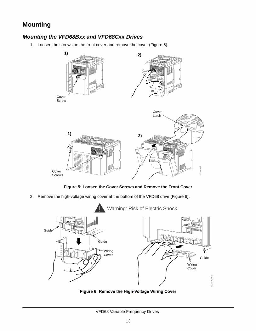
Mounting the VFD68Bxx and VFD68Cxx Drives1. Loosen the screws on the front cover and remove the cover (Figure 5).
2. Remove the high-voltage wiring cover at the bottom of the VFD68 drive (Figure 6).
Figure 5: Loosen the Cover Screws and Remove the Front Cover
CoverScrews
CoverScrew
1)
1) 2)
2)
Cover Latch
FIG
:cvr
_rm
vl
Figure 6: Remove the High-Voltage Wiring Cover
Guide
Guide
WiringCover
Guide
Guide
WiringCover
! Warning: Risk of Electric ShockF
IG:R
MV
_CV
R
VFD68 Variable Frequency Drives
13

Mount the VFD vertically (Figure 7) in an acceptable NEMA-rated enclosure on a non-flammable surface. When you drill mounting holes and mount the VFD, ensure that you do not allow metal chips or other material to enter the VFD housing.
See Figure 8 and Table 10 for mounting space requirements.
Table 10: Required ClearanceDimension 3.7 kW (5 HP) or Less 5.5–7.5 kW (7-1/2–10 HP)
A 100 mm (4 in.) or more 100 mm (4 in.) or more
B 10 mm (7/16 in.) or more 50 mm (2 in.) or more
C
Figure 7: Mount the VFD68 Drive
2 to 10 HP, 230 VAC1/2 to 10 HP, 460 VAC
1/8 to 1 HP, 230 VAC
Front cover
Wiring cover
Front cover
Wiring cover
FIG
:VFD
68_i
nstll
Figure 8: Required Clearance for Mounting Inside an Enclosure
5.5 to 7.5 kW (7-1/2 to 10 HP)
FIG
:clr
nc_r
qrdSide
VFD
3.7 kW (5 HP) or Less
C
A
A
Front
VFD VFDB BB
A A
A A
SideFront
VFD VFD VFD
A A A
A A A
B B B C
VFD68 Variable Frequency Drives
14

Mounting the VFD68Dxx Drives1. To remove the front cover, push down on the hooks at Position A and Position B and pull the front cover
away from the VFD68 drive, using the hooks at Position C as supporting points (Figure 9).
2. Remove the high-voltage wiring cover at the bottom of the VFD68 drive by pulling in the direction of Arrow A (Figure 10).
Mount the VFD vertically in an acceptable NEMA-rated enclosure on a non-flammable surface. When you drill the mounting holes and mount the VFD, ensure that you do not allow metal chips or other material to enter the VFD housing.
Figure 9: Release the Hooks and Remove the Front Cover
Figure 10: Remove the High-Voltage Wiring Cover
Wiring Hole
VFD68 Variable Frequency Drives
15

See Figure 11 and Table 11 for mounting space requirements.
Wiring
Table 11: Required ClearanceDimension 3.7 kW (5 HP) or Less 5.5 to 7.5 kW(7-1/2 to 10 HP)
A 100 mm (4 in.) or more 100 mm (4 in.) or more
B 10 mm (7/16 in.) or more 50 mm (2 in.) or more
C
!WARNING: Risk of Electric Shock.Disconnect the power supply before making electrical connections. Contact with components carrying hazardous voltage can cause electric shock and may result in severe personal injury or death.
AVERTISSEMENT: Risque de décharge électrique.Débrancher l'alimentation avant de réaliser tout branchement électrique. Tout contact avec des composants porteurs de tensions dangereuses risque d'entraîner une décharge électrique et de provoquer des blessures graves, voire mortelles.
!WARNING: Risk of Electric Shock.Do not touch any exposed metal parts with anything other than properly insulated tools or insulated probes of the digital voltage meter. Failure to use properly insulated tools and probes may result in severe personal injury or death.
AVERTISSEMENT: Risque de décharge électrique.Ne jamais toucher une partie métallique exposée avec tout élément autre que des outils correctement isolés ou les sondes isolées du voltmètre numérique. L'utilisation d'outils et de sondes incorrectement isolés risque de provoquer des blessures graves, voire mortelles.
Figure 11: Required Clearance for Mounting Inside an Enclosure
5.5 to 7.5 kW (7-1/2 to 10 HP)
FIG
:clr
nc_r
qrdSide
VFD
3.7 kW (5 HP) or Less
C
A
A
Front
VFD VFDB BB
A A
A A
SideFront
VFD VFD VFD
A A A
A A A
B B B C
VFD68 Variable Frequency Drives
16
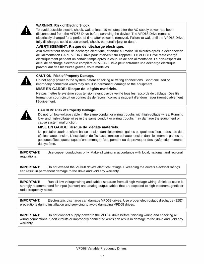
!WARNING: Risk of Electric Shock.To avoid possible electric shock, wait at least 10 minutes after the AC supply power has been disconnected from the VFD68 Drive before servicing the device. The VFD68 Drive remains electrically charged for a period of time after power is removed. Failure to wait until the VFD68 Drive fully discharges could cause electric shock, personal injury, or death.
AVERTISSEMENT: Risque de décharge électrique.Afin d'éviter tout risque de décharge électrique, attendre au moins 10 minutes après la déconnexion de l'alimentation CA du VFD68 Drive pour intervenir sur l'appareil. Le VFD68 Drive reste chargé électriquement pendant un certain temps après la coupure de son alimentation. Le non-respect du délai de décharge électrique complète du VFD68 Drive peut entraîner une décharge électrique provoquant des blessures graves, voire mortelles.
!CAUTION: Risk of Property Damage.Do not apply power to the system before checking all wiring connections. Short circuited or improperly connected wires may result in permanent damage to the equipment.
MISE EN GARDE: Risque de dégâts matériels.Ne pas mettre le système sous tension avant d'avoir vérifié tous les raccords de câblage. Des fils formant un court-circuit ou connectés de façon incorrecte risquent d'endommager irrémédiablement l'équipement.
!CAUTION: Risk of Property Damage.Do not run low-voltage cable in the same conduit or wiring troughs with high-voltage wires. Running low- and high-voltage wires in the same conduit or wiring troughs may damage the equipment or cause system malfunction.
MISE EN GARDE: Risque de dégâts matériels.Ne pas faire courir un câble basse tension dans les mêmes gaines ou goulottes électriques que des câbles haute tension. L'installation de fils basse tension et haute tension dans les mêmes gaines ou goulottes électriques risque d'endommager l'équipement ou de provoquer des dysfonctionnements du système.
IMPORTANT: Use copper conductors only. Make all wiring in accordance with local, national, and regional regulations.
IMPORTANT: Do not exceed the VFD68 drive's electrical ratings. Exceeding the drive's electrical ratings can result in permanent damage to the drive and void any warranty.
IMPORTANT: Run all low-voltage wiring and cables separate from all high-voltage wiring. Shielded cable is strongly recommended for input (sensor) and analog output cables that are exposed to high electromagnetic or radio frequency noise.
IMPORTANT: Electrostatic discharge can damage VFD68 drives. Use proper electrostatic discharge (ESD) precautions during installation and servicing to avoid damaging VFD68 drives.
IMPORTANT: Do not connect supply power to the VFD68 drive before finishing wiring and checking all wiring connections. Short circuits or improperly connected wires can result in damage to the drive and void any warranty.
VFD68 Variable Frequency Drives
17

PrecautionsBefore you apply power to the VFD68 drive and controlled motor, always recheck the following items:
• Connect the VFD only to three-phase induction motors. Connecting the VFD to other electrical equipment may cause damage.
• Applying power to the output terminals (U, V, W) of the VFD will damage the VFD. Never connect supply power to the drive’s output terminals.
• If you wire multiple motors to the VFD output, run separate wires to each motor. Do not use daisy-chain wiring.
• Do not install a power factor correction capacitor, surge suppressor, or capacitor type filter on the VFD output side. These devices can cause the VFD to trip, or they can damage the capacitor and surge suppressor.
• A high voltage charge remains in the VFD electronic components for a short time after the power is switched off.
Wait at least 10 minutes after the power supply has been switched off to allow the electric charge and heat to dissipate. Using a voltmeter, make sure that the voltage across the main circuit terminals P/+ and N/- of the VFD is no more than 30 VDC.
• A short circuit or earth (ground) fault on the VFD output side can damage the VFD.
- Check the insulation resistance of the circuit before you operate the VFD; repeated short circuits may damage the VFD. These short circuits may be caused by peripheral circuit inadequacy, an earth (ground) fault due to wiring inadequacy, or reduced motor insulation resistance.
- Check the ground (to-earth) insulation and phase-to-phase insulation of the VFD output side before applying power.
Carefully check the motor insulation resistance, especially when the VFD is used with an old motor or a motor located in unfavorable conditions.
• Do not exceed the permissible voltage to the VFD I/O signal circuits.
Application of a voltage higher than the permissible voltage to the VFD I/O signal circuits, or applying voltage of opposite polarity, may damage the I/O devices.
• Do not short circuit the +VDC excitation voltage outputs (terminals 10 and PC) to common (terminals: 5 and SD). Shorting the excitation voltage outputs to common may damage the VFD.
• Prevent VFD-generated EMI from causing functional problems.
- Do not run the low-voltage signal cables and the high-voltage power cables in parallel with each other, and do not bundle them together.
- Run low-voltage signal cables as far away as possible from high-voltage power cables.
- Use shielded cables for the low-voltage signal cables. Connect the sensor cable shield at only one point and that one point is the same terminal as the sensor's common wire.
- Install a ferrite core on the signal cable (for example, ZCAT3035-1330 TDK).
VFD68 Variable Frequency Drives
18

Terminal Screw Torque SpecificationsTighten the terminal screw to the specified torque. Overtightening the terminal screws may damage the terminal blocks and screw threads. Loose terminal screw connections can result in a short circuit or malfunction.
Branch Circuit ProtectionIntegral solid-state short circuit protection does not provide branch circuit protection. The installer must provide branch circuit protection in accordance with the National Electrical Code for the U.S. or the Canadian Electrical Code for Canada and any additional codes.
As specified, UL Class T fuses (or any faster acting fuse with the appropriate rating) or Listed UL 489 Molded Case Circuit Breaker (MCCB) must be employed in accordance with Table 15 and Table 16.
Table 12: Torque Specifications for VFD66Bxx DrivesRated Capacity, kW (HP) Terminal Screw Size1
1. The terminal screw size indicates the terminal size for R/L1, S/L2, T/L3, U, V, W, PR, P/+, N/-, P1, and earthing (grounding). The terminal screw size for earthing (grounding) appears in parenthesis if it is a different size.
Tightening Torque, N•m (lb•in.)
0.1–0.75 (1/8–1) M3.5 1.2 (10.6)
1.5–3.7 (2–5) M4 1.5 (13.3)
5.5–11 (7.5–15) M5 2.5 (22.2)
15 (20) M6 (M5) 4.4 (39)
Table 13: Torque Specifications for VFD68Cxx DrivesRated Capacity, kW (HP) Terminal Screw Size1
1. The terminal screw size indicates the terminal size for R/L1, S/L2, T/L3, U, V, W, PR, P/+, N/-, P1, and earthing (grounding). The terminal screw size for earthing (grounding) appears in parenthesis if it is a different size.
Tightening Torque, N•m (lb•in.)
0.4–11 (1/2–15) M4 1.5 (13.3)
15 (20) M5 2.5 (22)
Table 14: Torque Specifications for VFD68Dxx DrivesRated Capacity, kW (HP) Terminal Screw Size1
1. The terminal screw size indicates the terminal size for R/L1, S/L2, T/L3, U, V, W, PR, P/+, N/-, P1 and a screw for earthing (grounding).
Tightening Torque, N•m
0.75–7.5 (1–10) M4 1
Table 15: VFD68Bxx Drives Electrical Ratings230 VAC kW (HP)
0.1 (1/8)
0.2 (1/4)
0.4 (1/2)
0.75 (1)
1.5 (2)
2.2 (3)
3.7 (5)
5.5 (7.5)
7.5 (10)
11 (15)
15 (20)
Rated fuse voltage (V) 240 V or more
Fuse maximum allowable rating (A) (without power factor improving reactor)1
1. Maximum allowable rating by US National Electrical Code. Exact size must be chosen for each installation.
15 15 15 20 30 40 60 70 80 150 175
Molded case circuit breaker (MCCB) Maximum allowable rating (A)1
15 15 15 15 20 25 40 60 80 110 150
VFD68 Variable Frequency Drives
19

Short Circuit Ratings
The VFD68 drives meet the requirements for their respective rating categories (Table 18).
High-Voltage Wire Size and Maximum Wire Length
Use UL Listed copper stranded wire with insulation rated at 75°C (167°F) for wiring the high-voltage supply to the drive (R/L1, S/L2, T/L3) and wiring the high-voltage drive output (U, V, W) to the motor.
Selecting the Correct VFD68 Drive for Your Fan Motor
1. Determine the maximum current consumption from the motor ratings label.
2. Select the appropriate table for your motor’s current type.
• For 230 VAC motors, see Table 19.
• For 460 VAC motors, see Table 20.
• For 575 VAC motors, see Table 21.
Table 16: VFD68Cxx Electrical Ratings460 VAC kW (HP)
0.4 (1/2)
0.75 (1)
1.5 (2)
2.2 (3)
3.7 (5)
5.5 (7.5)
7.5 (10)
11 (15)
15 (20)
Rated fuse voltage (V) 480 V or more
Fuse maximum allowable rating (A) (without power factor improving reactor)1
6 10 15 20 30 40 70 80 90
Molded case circuit breaker (MCCB) Maximum allowable rating (A)1
15 15 15 15 20 30 40 50 70
1. Maximum allowable rating by US National Electrical Code. Exact size must be chosen for each installation.
Table 17: VFD68Dxx Drives Electrical Ratings575 VAC kW (HP)
0.75 (1) 1.5 (2) 2.2 (3) 3.7 (5) 5.5 (7.5) 7.5 (10)
Rated fuse voltage (V) 575 V or more
Fuse maximum allowable rating (A) (without power factor improving reactor)1
6 A 10 A 15 A 20 A 30 A 40 A
Molded case circuit breaker (MCCB) maximum allowable rating (A)1
5 A 10 A 15 A 20 A 30 A 30 A
1. Maximum allowable rating by US National Electrical Code. Exact size must be chosen for each installation.
Table 18: VFD68 Drives Short Circuit RatingsRating Category Suitable for use in a circuit capable of delivering not more than
VFD68Bxx Drives (230 VAC Class) 100 kA rms symmetrical amperes, 264 V maximum
VFD68Cxx Drives (460 VAC Class) 100 kA rms symmetrical amperes, 528 V maximum
VFD68Dxx Drives (575 VAC Class) 100 kA rms symmetrical amperes, 600 V maximum
IMPORTANT: Use copper conductors only. Make all wiring in accordance with local, national, and regional regulations.
VFD68 Variable Frequency Drives
20

3. In the table that you just selected, find the maximum output current that just exceeds the motor’s maximum current consumption and use the VFD68 Part Number associated with this maximum output current as the recommended Drive for the motor.
4. Use the same table to determine the recommended cable wiring size for the output current rating.
Table 19: 230 VAC, VFD68Bxx Drives, Maximum Output Amperes and Wiring SizesPart Number
Rated Capacity, kW (HP)
Maximum Output Current
(Amperes)
Cable Wire Size
AWG1
1. The recommended cable wire size is that of the cable (THHW cable) with a continuous maximum permissible temperature of 75°C (167°F). Assumes that the surrounding air temperature is 40°C (104°F) or less. (Selection example for use mainly in the United States.)
PVC wires, (mm2)2
2. The recommended cable wire size is that of the cable (PVC cable) with a continuous maximum permissible temperature of 70°C (158°F). Assumes that the surrounding air temperature is 40°C (104°F) or less. (Selection example for use mainly in Europe.)
R/L1, S/L2, T/L3
U, V, W R/L1, S/L2, T/L3
U, V, W Earthing (Ground) cable
VFD68BBB 0.1 (1/8) 0.8 14 14 2.5 2.5 2.5
VFD68BCB 0.2 (1/4) 1.4 14 14 2.5 2.5 2.5
VFD68BDC 0.4 (1/2) 2.5 14 14 2.5 2.5 2.5
VFD68BFD 0.75 (1) 4.2 14 14 2.5 2.5 2.5
VFD68BGG 1.5 (2) 7.0 14 14 2.5 2.5 2.5
VFD68BHG 2.2 (3) 10.0 14 14 2.5 2.5 2.5
VFD68BJK 3.7 (5) 16.5 12 12 4 4 4
VFD68BKL 5.5 (7-1/2) 23.8 10 10 6 6 6
VFD68BLL 7.5 (10) 31.8 6 8 16 10 6
VFD68BMP 11 (15) 45.0 6 6 16 16 16
VFD68BNP 15 (20) 58.0 4 4 25 25 16
Table 20: 460 VAC, VFD68Cxx Drives, Maximum Output Amperes and Wiring Sizes Part Number
Rated Capacity, kW (HP)
Maximum Output Current
(Amperes)
Cable Wire Size
AWG1
1. The recommended cable wire size is that of the cable (THHW cable) with a continuous maximum permissible temperature of 75°C (167°F). Assumes that the surrounding air temperature is 40°C (104°F) or less. (Selection example for use mainly in the United States.)
PVC wires, (mm2)2
2. The recommended cable wire size is that of the cable (PVC cable) with a continuous maximum permissible temperature of 70°C (158°F). Assumes that the surrounding air temperature is 40°C (104°F) or less. (Selection example for use mainly in Europe.)
R/L1, S/L2, T/L3
U, V, W R/L1, S/L2, T/L3
U, V, W Earthing (Ground) cable
VFD68CDF 0.4 (1/2) 1.2 14 14 2.5 2.5 2.5
VFD68CFF 0.75 (1) 2.2 14 14 2.5 2.5 2.5
VFD68CGG 1.5 (2) 3.6 14 14 2.5 2.5 2.5
VFD68CHH 2.2 (3) 5.0 14 14 2.5 2.5 2.5
VFD68CJJ 3.7 (5) 8.0 14 14 2.5 2.5 2.5
VFD68CKL 5.5 (7.5) 12.0 12 14 4 2.5 4
VFD68CLL 7.5 (10) 16.0 12 12 4 4 4
VFD68CMP 11 (15) 23.0 10 10 6 6 10
VFD68CNP 15 (20) 29.5 8 8 10 10 10
VFD68 Variable Frequency Drives
21

Calculating the Maximum Wire Length
Use the following steps to determine the maximum wire length.
1. Use the recommended wire size in accordance with local, national, and regional regulations to determine the electrical resistance of the wire (R) according to Table 22.
2. Find the rated voltage (V) and maximum output current (I) from the rating plate on the selected VFD68 drive.
Table 21: 575 VAC, VFD68Dxx Drives, Maximum Output Amperes and Wiring Sizes
Part Number
Rated Capacity, kW (HP)
Maximum Output Current (Amperes)
Cable Wire Size
AWG1 PVC wires, (mm2)2
R/L1, S/L2, T/L3
U, V, W R/L1, S/L2, T/L3
U, V, W Earthing (Ground) Cable
VFD68DFM 0.75 (1) 1.7 14 14 2 2 3.5
VFD68DGM 1.5 (2) 2.7 14 14 2 2 3.5
VFD68DHM 2.2 (3) 4.0 14 14 2 2 3.5
VFD68DJN 3.7 (5) 6.1 14 14 2 2 3.5
VFD68DKN 5.5 (7-1/2) 9.0 14 14 2 2 5.5
VFD68DLN 7.5 (10) 12.0 12 14 3.5 2 5.5
1. The recommended cable wire size is that of the cable (THHW cable) with a continuous maximum permissible temperature of 75°C (167°F). Assumes that the surrounding air temperature is 40°C (104°F) or less. (Selection example for use mainly in the United States.)
2. The recommended cable wire size is that of the cable (PVC cable) with a continuous maximum permissible temperature of 70°C (158°F). Assumes that the surrounding air temperature is 40°C (104°F) or less. (Selection example for use mainly in Europe.)
Table 22: Electrical Resistance by Wire SizeRecommended
Wire Size1
1. The mm wire sizes that are given as equivalences to the AWG wire sizes are not commercially available.
Electrical Resistance of Wire (milliohms/meter)
Recommended Wire Size1
Electrical Resistance of Wire (milliohms/meter)
25 mm2 0.727 5.3 mm2 (10 AWG) 3.28
21.2 mm2 (4 AWG) 0.815 4 mm2 4.61
16 mm 1.15 3.3 mm2 (12 AWG) 5.21
13.3 mm2 (6 AWG) 1.30 2.5 mm2 7.41
10 mm2 1.83 2 mm2 (14 AWG) 8.28
8.3 mm2 (8 AWG) 2.06 1.5 mm2 12.1
6 mm2 3.08
VFD68 Variable Frequency Drives
22
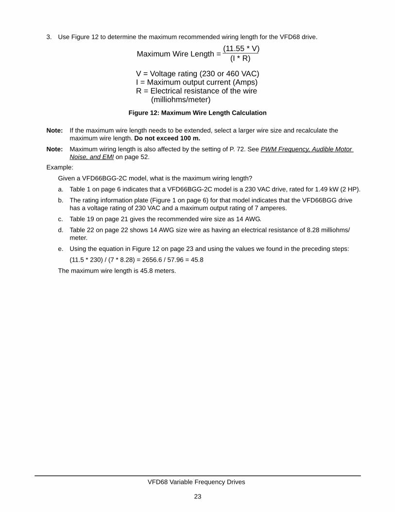
3. Use Figure 12 to determine the maximum recommended wiring length for the VFD68 drive.
Note: If the maximum wire length needs to be extended, select a larger wire size and recalculate the maximum wire length. Do not exceed 100 m.
Note: Maximum wiring length is also affected by the setting of P. 72. See PWM Frequency, Audible Motor Noise, and EMI on page 52.
Example:
Given a VFD66BGG-2C model, what is the maximum wiring length?
a. Table 1 on page 6 indicates that a VFD66BGG-2C model is a 230 VAC drive, rated for 1.49 kW (2 HP).
b. The rating information plate (Figure 1 on page 6) for that model indicates that the VFD66BGG drive has a voltage rating of 230 VAC and a maximum output rating of 7 amperes.
c. Table 19 on page 21 gives the recommended wire size as 14 AWG.
d. Table 22 on page 22 shows 14 AWG size wire as having an electrical resistance of 8.28 milliohms/meter.
e. Using the equation in Figure 12 on page 23 and using the values we found in the preceding steps:
(11.5 * 230) / (7 * 8.28) = 2656.6 / 57.96 = 45.8
The maximum wire length is 45.8 meters.
Figure 12: Maximum Wire Length Calculation
V = Voltage rating (230 or 460 VAC)I = Maximum output current (Amps)R = Electrical resistance of the wire (milliohms/meter)
Maximum Wire Length = (11.55 * V)
(I * R)
VFD68 Variable Frequency Drives
23

High-Voltage Wiring Connections
Making High-Voltage Wiring Connections on VFD68Bxx and VFD68Cxx Drives
1. Loosen the screws on the front cover and remove the cover to access the low-voltage wiring (Figure 13).
2. Remove the high-voltage wiring cover at the bottom of the VFD68 drive (Figure 14).
Figure 13: Loosen the Cover Screws and Remove the Front Cover
CoverScrews
CoverScrew
1)
1) 2)
2)
Cover Latch
FIG
:cvr
_rm
vl
Figure 14: Remove the High-Voltage Wiring Cover
Guide
Guide
WiringCover
Guide
Guide
WiringCover
! Warning: Risk of Electric ShockF
IG:R
MV
_CV
R
VFD68 Variable Frequency Drives
24

3. For supplied three-phase power, connect the high-voltage power supply to terminals R/L1, S/L2, and T/L3 on the drive (Figure 15).
For supplied single-phase power, connect the high-voltage power supply to terminals L1 and L3 (Figure 15).
4. Connect the motor wiring to high-voltage output terminals U, V, and W on the drive (Figure 15).
5. Connect earth ground wiring to the earth ground terminals on the VFD68 drive and on the motor.
6. Replace the high-voltage wiring cover.
Note: When replacing the high-voltage cover, carefully space and position the leads through the vents or wire slots.
IMPORTANT: Use UL Listed copper, stranded wire with insulation rated at 75°C (167°F) for wiring in Step 3 and Step 4. See High-Voltage Wire Size and Maximum Wire Length on page 20.
Figure 15: High-Voltage Terminal Block Wiring
VFD68 Variable Frequency Drives
25

Making High-Voltage Wiring Connections on VFD68Dxx Drives
1. Push down on the hooks at Position A and Position B and pull it away from the VFD68 drive, using the hooks at Position C as supporting points (Figure 16).
2. Remove the high-voltage wiring cover at the bottom of the VFD68 drive by pulling in the direction of Arrow A (Figure 14).
Figure 16: Release the Hooks and Remove the Front Cover
Figure 17: Remove the High-Voltage Wiring Cover
Wiring Hole
VFD68 Variable Frequency Drives
26

3. Connect a 575 VAC three-phase power supply to Terminals R/L1, S/L2, and T/L3 (Figure 18).
For supplied three-phase power, connect the high-voltage power supply to terminals R/L1, S/L2, and T/L3 on the drive (Figure 18).
For supplied single-phase power, connect the high-voltage power supply to terminals L1 and L3 (Figure 18).
4. Connect the motor wiring to high-voltage output terminals U, V, and W on the drive (Figure 18).
5. Connect earth ground wiring to the earth ground terminals on the VFD68 drive and on the motor.
6. Replace the high-voltage wiring cover.
Note: When replacing the high-voltage cover, carefully space and position the leads through the vents or wire slots.
IMPORTANT: Use UL Listed copper, stranded wire with insulation rated at 75°C (167°F) for wiring in Step 3 and Step 4. See High-Voltage Wire Size and Maximum Wire Length on page 20.
Figure 18: High-Voltage Terminal Block Wiring
Jumper
IM
N/- P/+
R/L1 S/L2 W
VFD68 Variable Frequency Drives
27

Low-Voltage Wiring Connections
Making Low-Voltage Wiring Connections on VFD68Bxx and VFD68Cxx Drives
Low-voltage wiring terminals are located underneath the front cover. See Figure 19 and Table 23.
IMPORTANT: If using two input devices, both devices must be identical. Do not use input devices with different ranges and operating characteristics.
Table 23: VFD68Bxx and VFD68Cxx Drives Low-Voltage Connections Information1 (Part 1 of 2)Terminal Label
Signal Type Description
10 +5VDC Provides + 5 VDC supply for P499R transducers (15 mA maximum)
2 Analog Input Analog Input 1 (AI1) accepts 0–5 V or 0–10 V DC analog input signals
5 Analog Common Common for analog inputs
4 Analog Input Analog Input 2 (AI2) accepts 0–5 V, 0–10 V, or 4–20 mA analog input signals
AM Analog Output Provides a 0–10 VDC analog output signal corresponding to output frequency
RUN Open Collector Transistor Output
VFD Running - Switched low (transistor conducts) when the VFD output frequency is higher than the start frequency (the motor is running). Switched high (transistor is off) when the motor is off.
SE Open Collector Common
Common for RUN terminal
SO Open Collector Transistor Output
Safety Stop Output
S1 Safety Stop Input Terminals S1 and S2 must connect to terminal SC or the VFD shuts off.
S2 Safety Stop Input Terminals S1 and S2 must connect to terminal SC or the VFD shuts off.
Figure 19: VFD68Bxx and VFD68Cxx Drives Low-Voltage Connections
10 AM2 5 4
SO S1 S2
RM
FIG
:vfd
68_l
w_v
ltg_c
nnct
ns
(+5
V)
(AI1
)
(AC
OM
)
(AI2
)
(Saf
ety
Sto
p In
put)
(Saf
ety
Sto
p In
put)
(Com
mon
)
(+24
VD
C)
(Co
mm
on)
(For
war
d)
( R
eve
rse
)
Contact Inputs
(Sa
fety
Sto
p C
om
mon
)
Current: I
Volts: V
SW8
AI2 Mode Switch
VFD68 Variable Frequency Drives
28

To connect the input signal devices:
1. Loosen the screws on the front cover and remove the cover to access the low-voltage wiring (Figure 13 on page 24).
2. Locate the low-voltage wiring terminals (Figure 20).
SC Safety Stop Common
Common for S0, S1, and S2 terminals
SD Common Common for + 24 VDC Supply and contact inputs (using Sink logic - default setting)
RL Contact Input Run Low Speed
RM Contact Input Run Medium Speed
RH Contact Input Run High Speed
SD Common Common for + 24 VDC Supply and contact inputs (when using Sink logic - default setting)
PC +24 VDC Provides + 24 VDC excitation voltage, 100 mA maximum, Use for P499A or P499V transducers.
STF Contact Input Forward rotation. Connect STF to SD terminal (common) to enable VFD to rotate forward.
STR Contact Input Reverse rotation (used to reverse motor rotation)
A Relay Output (N.O.) During normal operation, relay contacts A and C are open. (maximum alarm load: 230 VAC, 0.3 A or 30 VDC, 0.3 A)
B Relay Output (N.C.) During normal operation, relay contacts B and C are connected. (maximum alarm load: 230 VAC, 0.3 A or 30 VDC, 0.3 A)
C Relay Output (C) Relay output common
1. Gray cells indicate a terminal that is typically not used in condenser fan speed control applications.
Terminal RL (Run Low Speed) corresponds to P. 6; Terminal RM (Run Medium Speed) corresponds to P. 5; Terminal RH (Run High Speed) corresponds to P. 4. When one of these terminals is connected to SD (common) the VFD runs at the speed shown in the corresponding parameter.
Terminal STR (reverse rotation) is disabled by P. 78 setting = 1. This terminal is not useful for condenser fan speed control applications.
Terminals A, B, and C are connected to relay contacts that activate when a fault has occurred and the VFD output has stopped.
Table 23: VFD68Bxx and VFD68Cxx Drives Low-Voltage Connections Information1 (Part 2 of 2)Terminal Label
Signal Type Description
Figure 20: Locating the Low-Voltage Wiring Terminals
PCSDRHRMRL
AM
CBA
10 2 5 4
RUN SE S1 S2 SCSO SD
FIG
:cnt
rl_c
rct_
trm
nl_l
yt
SIN
K
SO
UR
CE
VFD68 Variable Frequency Drives
29

3. Push down on the orange tab to open the terminal (Figure 21).
4. Insert the wire and release the orange tab to secure the wire.
5. Wire the input devices to the analog input terminals (see Low-Voltage Wiring Connections on page 28) and make any necessary parameter adjustments.
6. Replace the front cover.
IMPORTANT: Do not pull the wires out of the terminal block without pushing the orange tab all the way down. Pulling wires out of the low-voltage terminal block without opening the terminal may damage the terminal block or circuit board.
Figure 21: Wiring Analog Input Devices to the VFD68 Control
Open/close tab Flatheadscrewdriver
VFD68 Variable Frequency Drives
30

Making Low-Voltage Wiring Connections on VFD68Dxx Drives
Low-voltage wiring terminals are located underneath the front cover. See Figure 22, Table 24, and Table 25. After you finish making the low-voltage wiring connections, replace the front cover (Figure 16 on page 26).
Table 24: VFD68Dxx Drives Low-Voltage Connection Information for the Primary Board (Part 1 of 2)Terminal
Label1Signal Type Description
RH Contact Input Run High Speed
RM Contact Input Run Medium Speed
RL Contact Input Run Low Speed
MRS Contact Input Current Input Selection - Connect terminal MRS to terminal SD to enable the 4–20 mA input, Analog Input 2 (AI2).
RES Contact Input Reset - Turn on the RES signal (100 ms or longer) to turn off the VFD output and reset the thermal relay and regenerative brake circuits
SD Common Common for contact inputs (using Sink logic - default setting) and 24 VDC supply
AM Analog Output 0–10 VDC analog output corresponding to output frequency
PC +24V +24 VDC Supply
SE Open Collector Common
Common for RUN terminal
RUN Open Collector Transistor Output
VFD Running - Switched low (transistor conducts) when the VFD output frequency is higher than the start frequency (the motor is running). Switched high (transistor is off) when the motor is off.
FU Open Collector Transistor Output
Frequency detection output - switched low (transistor conducts) when VFD output frequency has reached or exceeded the detection frequency. Switched high (transistor is off) when VFD output frequency is below detection frequency.
A Relay Output (N.O.) During normal operation, relay contacts A and C are connected. (maximum alarm load: 230 VAC, 0.3 A or 30 VDC, 0.3 A).
Figure 22: VFD68Dxx Drives Connection Information
VFD68 Variable Frequency Drives
31

Input Wiring Connections
Making Input Wiring Connections on VFD68Bxx and VFD68Cxx Drives
Wire the input device to the analog input terminals (Table 26) and make any necessary parameter adjustments. See Setup and Adjustment on page 38 and Parameter Setting Calculations for Motor Speed vs. Pressure on page 49 for more information.
B Relay Output (N.C.) During normal operation, relay contacts B and C are connected (maximum alarm load: 230 VAC, 0.3 A or 30 VDC, 0.3 A).
C Relay Output (C) Relay output common
10 +5 V +5 VDC Supply for P499R transducers (15 mA maximum)
2 Analog Input Analog Input 1 (AI1) accepts 0–5 V or 0–10 V DC analog input signals
5 Analog Common Common for analog inputs
4 Analog Input Analog Input 2 (AI2) accepts 4–20 mA analog input signals
SD Common Common for contact inputs (when using Sink logic - default setting).
STF Contact Input Forward rotation. Must connect STF to SD terminal (common) using factory supplied jumper to allow VFD to rotate in a forward direction.
STR Contact Input Reverse rotation (not used)
SD Common Common for contact inputs (when using Sink logic - default setting).
1. Gray cells indicate a terminal that is typically not used in condenser fan speed control applications.
Table 25: VFD68Dxx Drives Low-Voltage Connection Information for the High Input Signal Select Board
Terminal Label
Signal Type Description
5V +5V +5 VDC Supply for P499R transducers (15 mA maximum)
IN1 Analog Input Analog Input 1 for 0.5 to 4.5 V Ratiometric High Signal Select
GND Analog Common Common for analog inputs
5V +5V +5 VDC Supply for P499R transducers (15 mA maximum)
IN2 Analog Input Analog Input 2 for 0.5 to 4.5 V Ratiometric High Signal Select
GND Analog Common Common for analog inputs
Table 26: Wiring P499 Transducers as Input DevicesSignal P499R Ratiometric Transducers Analog Input Terminal
AI1 White wire of first transducer Terminal 2
AI2 White wire of second transducer Terminal 4
+5 V Red wire Terminal 10
ACOM Black wire Terminal 5
Table 24: VFD68Dxx Drives Low-Voltage Connection Information for the Primary Board (Part 2 of 2)Terminal
Label1Signal Type Description
VFD68 Variable Frequency Drives
32

0.5–4.5 VDC Ratiometric P499 Transducer
The default parameter values (Table 34 on page 43) on the VFD68 drive are configured to operate a condenser fan motor on an R410 condensing unit, using a P499RCP-107 or P499RAP-107 ratiometric transducer (or transducers). Wire one transducer for single circuit condensing systems. Wire two transducers for dual circuit condensing systems (Figure 23).
The VFD68 has the ability to control motor speed using the higher input signal value of two voltage inputs when you configure AI1 and AI2 as the same model transducer. For the high-input signal select application with two transducers (Figure 23 on page 33 or Figure 24 on page 34), use the parameter values in Table 28
and see Adjusting the Default Parameters on page 52.
For high-pressure refrigerants other than R410a, you must calculate and change the C x parameters. For medium and low pressure refrigerants, you must determine the proper P499R transducer and then calculate and change the C x parameters.
For more information, see Setup and Adjustment on page 38 and Parameter Setting Calculations for Motor Speed vs. Pressure on page 49.
Table 27: Settings for Single or Dual 0.5–4.5 VDC Ratiometric TransducersSetting Single Transducer Dual Transducer, High-Signal Select
P. 73 1
1. For information on parameters, see Table 34 on page 43.
1 (0–5 V) 1 (0–5 V)
P.266 1 1 (voltage input) 1 (voltage input)
P.267 1 1 (0–5 V) 1 (0–5 V)
Analog Input Terminal AI1 or AI2 AI1 and AI2
AI2 Mode Switch2
2. See Figure 19 on page 28.
V V
IMPORTANT: If using two input devices, both devices must be identical. Do not use input devices with different ranges and operating characteristics.
Figure 23: Wiring 0.5–4.5 VDC Ratiometric Input Signal Transducers
VFD68 Variable Frequency Drives
33

0–10 VDC P499 Transducer
For applications using a 0–10 VDC P499V transducer, you must:
• adjust the parameter values that are listed in Table 28
• ensure that the AI2 mode switch (Figure 19 on page 28) is set correctly
• calculate and change C x parameters based on the desired operating pressure range for the condensing fans on your application
The VFD68 has the ability to control motor speed using the higher input signal value of two voltage inputs when you configure AI1 and AI2 as the same model transducer. For the high-input signal select application with two transducers (Figure 23 or Figure 24), use the parameter values in Table 28 and see Figure 29 on page 40, VFD68Bxx and VFD68Cxx Drive Basic and Advanced Parameters on page 43, and Adjusting the
Default Parameters on page 52.
Table 28: Settings for Single or Dual 0–10 VDC TransducersSetting Single Transducer Dual Transducer, High-Signal Select
P. 73 1
1. For information on parameters, see Table 34 on page 43.
0 (0–10 V) 0 (0–10 V)
P.266 1 1 (voltage input) 1 (voltage input)
P.267 1 2 (0–10 V) 2 (0–10 V)
Analog Input Terminal AI1 or AI2 AI1 and AI2
AI2 Mode Switch2
2. See Figure 19 on page 28.
V V
IMPORTANT: If using two input devices, both devices must be identical. Do not use input devices with different ranges and operating characteristics.
Figure 24: Wiring 0–10 VDC Input Signal Transducers
VFD68 Variable Frequency Drives
34

4–20 mA P499 Transducer
For applications using a 4–20 mA P499A transducer (Figure 25), you must:
• set P.266 and P.267 to 0
• set the AI2 mode switch position to I (see VFD68Bxx and VFD68Cxx Drives on page 56)
• calculate and change the C x parameters based on the desired operating pressure range for the condensing fans on your application
Table 29: Settings for Single 4–20 mA TransducerSetting Single Transducer, 4–20 mA
P. 73 1
1. For information on parameters, see Table 34 on page 43.
N/A
P.266 1 0 (current input)
P.267 1 0 (4–20 mA)
Analog Input Terminal AI2
AI2 Mode Switch2
2. See Figure 19 on page 28.
I
Figure 25: Wiring a 4–20 mA Input Signal Transducer
VFD68 Variable Frequency Drives
35

Making Input Wiring Connections on VFD68Dxx Drives
Wire the input device to the analog input terminals (Table 26) and make any necessary parameter adjustments. See Setup and Adjustment on page 38 and Parameter Setting Calculations for Motor Speed vs. Pressure on page 49 for more information.
0.5–4.5 VDC Ratiometric P499 Transducer
The default parameter settings (Table 30) on the VFD68 drive are configured to operate a condenser fan motor on an R410 condensing unit, using a P499RCP-107 or P499RAP-107 ratiometric transducer (Figure 26).
For high-pressure refrigerants other than R410a, you must calculate and change the P.90x parameters. For medium and low pressure refrigerants, you must determine the proper P499R transducer and then calculate and change the P.90x parameters.
For more information, see Setup and Adjustment on page 38, VFD68Dxx Drive Parameters on page 46, and Figure 55 on page 90.
Table 30: Settings for a 0.5–4.5 VDC TransducerSetting 0–5 V
Analog Input Terminals IN1 and IN2
Figure 26: Wiring 0.5–4.5 VDC Ratiometric Input Signal Transducers
VFD68 Variable Frequency Drives
36

0–10 VDC or 4–20 mA P499 Transducer
For applications using a 0–10 VDC or 4–20 mA P499 transducer, you must:
• change parameter values in Table 31
• calculate and change P.902 and P.903 (for 0–10 V operation) or P.904 and P.905 (for 4–20 mA operation), based on the desired operating pressure range and motor speed for the condensing fans on your application. See VFD68Dxx Drives Operation Panel on page 41 and VFD68Dxx Drive Parameters on page 46 for more information.
Table 31: Settings for Single InputSetting 4–20 mA 0–10 V
P. 73 1
1. For information on parameters, see Table 35 on page 46.
Note: To enable AI2 (4–20 mA) and disable AI1, connect terminal MRS to terminal SD.
N/A 1 (0–10 V)
Analog Input Terminal AI2 AI1
Figure 27: Wiring a 4–20 mA Input Signal Transducer
Figure 28: Wiring a 0–10 V Input Signal Transducer
VFD68 Variable Frequency Drives
37

Setup and Adjustment
Correspondences Between Digital and Actual Characters
The actual alphanumeric characters correspond to the following digital characters displayed on the operation panel:
IMPORTANT: If the LED display shows an error code, press and see Troubleshooting on page 58 for a list of fault or alarm indications, probable causes, and corrective actions.
STOPRESETSTOP
RESET
Actual Digital
0
1
2
3
4
5
6
7
8
9
Actual Digital
A
B
C
E
F
G
H
I
J
L
D
Actual Digital
M
N
O
o
P
T
U
V
r
-
S
VFD68 Variable Frequency Drives
38

VFD68Bxx and VFD68Cxx Operation Panel
Operation Modes
The VFD68 drive’s mode of operation is indicated by the mode of operation LEDs (labeled PU, EXT, and NET) on the drive’s operation panel (Figure 29).
PU Mode: The Parameter Units (PU) mode is manual control mode. In PU mode, the drive and motor are completely controlled using the buttons and the setting dial on the drive’s user interface. No external analog signals or network signals control the drive operation. The PU mode is typically used to set up, test, and troubleshoot the drive and motor operation using controlled input signal values.
EXT Mode: In the External (EXT) mode, the drive and motor respond to a signal or signals from one or two (external) analog input signal devices, such as pressure transducers or analog controllers. This is the typical mode of operation for the drive when it controls a condenser fan or other three-phase HVACR motor application.
PU/EXT Mode: In PU/EXT mode, the drive responds to the connected external signal devices and the drive setup values can be edited. The PU/EXT mode is typically used to set up your drive for initial operation, or to adjust setup parameters on an operating application.
NET Mode: In Network (NET) mode, the drive connects to and communicates over a network bus with other network devices and receives operating (Read/Write) commands from a master device on the network. The Network mode is not currently supported on VFD68 drives.
The VFD68 drives are RS485, RTU-compliant ModBus® slave devices. For more information, see Appendix 4: VFD68Bxx and VFD68Cxx ModBus RTU RS485 Communications Bus Specifications on page 90.
MON Mode: Shows motor speed represented as frequency (Hz) or RPM.
RUN, MON, PRM LEDs
The RUN, MON, and PRM LEDs provide drive status and indicate the type of information being displayed on the operation panel monitor.
RUN LED: The LED state (on steady, flashing, or flickering) provides information regarding the drive and motor run status. See Figure 29 for more information.
MON LED: Indicates that the monitor is displaying the drive’s run status. Press (SET) to scroll through run frequency, output amperes, and output voltage.
PRM LED: Indicates that the monitor is set to display parameters and parameter values and allows you to view and edit parameter values.
VFD68 Variable Frequency Drives
39
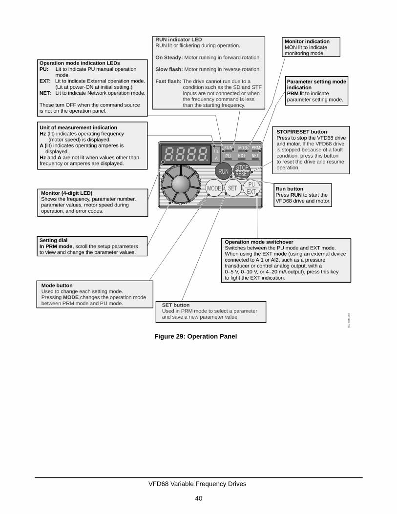
Figure 29: Operation Panel
RUN MON
NET
Operation mode indication LEDsPU:
EXT:
NET:
Lit to indicate PU manual operation mode.
Lit to indicate External operation mode. (Lit at power-ON at initial setting.)
Lit to indicate Network operation mode.
These turn OFF when the command source is not on the operation panel.
Unit of measurement indicationHz
A (
Hz A
(lit) indicates operating frequency (motor speed) is displayed.
lit) indicates operating amperes is displayed.
and are not lit when values other than frequency or amperes are displayed.
Monitor (4-digit LED)Shows the frequency, parameter number, parameter values, motor speed during operation, and error codes.
Setting dialIn PRM mode, scroll the setup parameters to view and change the parameter values.
Mode buttonUsed to change each setting mode.Pressing changes the operation modebetween PRM mode and PU mode.
MODE
SET buttonUsed in PRM mode to select a parameterand save a new parameter value.
Parameter setting mode indicationPRM lit to indicate parameter setting mode.
Monitor indicationMON lit to indicate monitoring mode.
STOP/RESET buttonPress to stop and motor.
the VFD68 drive If the VFD68 drive
is stopped because of a faultcondition, press this buttonto reset the drive and resume operation.
Operation mode switchoverSwitches between the PU mode and EXT mode. When using the EXT mode (using an external device connected to AI1 or AI2, such as a pressure transducer or control analog output, with a 0–5 V, 0 10 V, or 4 20 mA output), press this key to light the EXT indication.
– –
Run buttonRUNPress to start the
VFD68 drive and motor.
RUN indicator LED
On Steady:
Slow flash:
Fast flash:
RUN lit or flickering during operation.
Motor running in forward rotation.
Motor running in reverse rotation.
The drive cannot run due to a condition such as the SD and STF inputs are not connected or when the frequency command is less than the starting frequency.
FIG
:opr
tn_p
nl
VFD68 Variable Frequency Drives
40

VFD68Dxx Drives Operation Panel
Mode of Operation Icons
The VFD68 drive’s mode of operation is indicated by the mode of operation icons (labeled PU and EXT) on the drive’s operation panel (Figure 30).
PU Mode: The Parameter Units (PU) mode is manual control mode. In PU mode, the drive and motor are completely controlled using the buttons and the setting dial on the drive’s user interface. No external analog signals or network signals control the drive operation. The PU mode is typically used to set up, test, and troubleshoot the drive and motor operation using controlled input signal values.
EXT Mode: In the External (EXT) mode, the drive and motor respond to a signal or signals from one or two (external) analog input signal devices, such as pressure transducers or analog controllers. This is the typical mode of operation for the drive when it controls a condenser fan or other three-phase HVACR motor application.
PU/EXT Mode: In PU/EXT mode, the drive responds to the connected external signal devices and the drive setup values can be edited. The PU/EXT mode is typically used to set up your drive for initial operation, or to adjust setup parameters on an operating application.
MON Mode: Shows motor speed represented as frequency (Hz) or RPM.
Display Code
Parameter Setting Mode: When the display shows Pr.., the VFD68 drive displays parameter codes and parameter setting values.
• Press or to scroll through the parameter codes and to edit parameter setting values.
• Press to enter the 3-digit parameter code for viewing and editing.
Table 32: Operation Panel Keys (Part 1 of 2)Key Description
Used to give a start rotation command.
• Used to stop operation.• Used to reset the VFD68 Drive when the output stops due to activation of the protection function.
Used to select the operation mode or setting mode.
SET
Figure 30: Operation Panel
Unit indicationOperation statusindication
Reverse keySetting key
Mode key
RUN key STOP/RESET key Forward key STOP/RESET key UP/DOWN key
COVER OPENED:
REVSET
RESETRUN
RUN
STOPRESET
MODE
VFD68 Variable Frequency Drives
41

Used to determine the frequency and parameter settings.
• Used to increase or decrease the running frequency consecutively. Hold down the key to change the frequency.
• Used to change the parameter setting consecutively, when in the setting mode. Press the key to change the parameter setting.
Used to give a forward rotation command.
Used to give a reverse rotation command.
• Used to stop operation.• Used to reset the VFD68 Drive when the output stops due to activation of the protection function.
Table 33: Unit Indications and Operating Status IndicationsIndication Description
Hz Lit to indicate frequency
A Lit to indicate the current (Amperes)
RUN Lit to indicate drive operationSteady light = forward rotationFlickering light = reverse rotation
MON Lit to indicate monitor display mode
PU Lit to indicate the PU operation mode
EXT Lit to indicate the external operation mode
Table 32: Operation Panel Keys (Part 2 of 2)Key Description
SET
FWD
REV
STOPRESET
VFD68 Variable Frequency Drives
42

VFD68Bxx and VFD68Cxx Drive Basic and Advanced ParametersYou can use the default parameter setting with the P499RxP-107C transducer and R410a refrigerant within a range of operation that depends on the specific model of P499 transducer selected. All other applications require some parameter changes and may require different transducers.
The parameters shown highlighted in gray in Table 34 are the advanced parameters. To view and change these parameters, change P.160 from 9999 to 0.
Table 34: Basic and Advanced Parameter Descriptions for VFD68Bxx and VFD68Cxx Drives (Part 1 of 4)
ParameterIndication on Monitor
Description Range VFD68xxx-2 Defaults
P. 0 Torque Boost: Defines the voltage (% total V) applied to the motor when the drive starts the motor at 0 Hz.
0–30% 6%/4%/3%
P. 1 Maximum Frequency: Defines the maximum speed of the motor in your application. See Figure 31.
0–120 Hz 60 Hz
P. 2 Minimum Frequency: Defines the minimum speed of the motor in your application. See Figure 31.
0–120 Hz 12.5 Hz
P. 3 Base Frequency: Set parameter to the rated frequency [Hz] on motor rating plate.
0–400 Hz 60 Hz
P. 4 High Speed: The speed, or frequency, that the VFD68 output drives the attached motor when terminal RH is connected to terminal SD (common).
0–400 Hz 40 Hz
P. 5 Middle Speed: The speed, or frequency, that the VFD68 output drives the attached motor when terminal RM is connected to terminal SD (common).
0–400 Hz 20 Hz
P. 6 Low Speed: The speed, or frequency, that the VFD68 output drives the attached motor when terminal RL is connected to terminal SD (common).
0–400 Hz 10 Hz
P. 7 Acceleration Time: Defines the time required to accelerate from stop (0 Hz) to full rated RPM (60 Hz).
0–3600 seconds 15 seconds
P. 8 Deceleration Time: Defines the time required to decelerate from full rated RPM (60 Hz) to stop (0 Hz).
0–3600 seconds 15 seconds
P. 9 Motor Rated Current: Set parameter to the rated FLA (full load amperes) on motor rating plate.
0–500 A Rated VFD68 Output
P. 19 Base Frequency Voltage: Defines drive's maximum output voltage relative to the drive's supply voltage. (9999: drive's maximum output voltage is the same as the drive's power supply voltage.)
0–1000V, 9999 9999
P. 20 Acceleration/Deceleration Reference Frequency: Defines the high end frequency for P. 7 and P. 8.
0–400 Hz 60 Hz
P. 22 Stall Prevention Output Current Level: Defines the current level (as a percent of motor FLA) at which the drive begins to adjust the output frequency (Hz) to reduce the output current.
0–200% 150%
P. 31 Frequency Jump 1A: Frequency Jump parameters (P. 31 and P. 32) are used to set the low speed behavior of the drive. This parameter typically remains at 0 Hz.
0–400 Hz, 9999 0 Hz
P. 32 Frequency Jump 1B: maximum frequency to skip over to avoid very low fan airflow and unnecessary motor overheating (9999: frequency jump not enabled.)Ensure that P. 31 is set equal to C. 2 and C. 5
0–400 Hz, 9999 12.5 Hz
P. 33 Frequency Jump 2A: To avoid resonance noise caused by natural frequency of mechanical system, enter frequency just below noisy frequency 2.
0 to 400 Hz, 9999 9999
VFD68 Variable Frequency Drives
43

P. 34 Frequency Jump 2B: To avoid resonance noise caused by natural frequency of mechanical system, enter frequency just above noisy frequency 2.
0 to 400 Hz, 9999 9999
P. 35 Frequency Jump 3A: To avoid resonance noise caused by natural frequency of mechanical system, enter frequency just below noisy frequency 3.
0 to 400 Hz, 9999 9999
P. 36 Frequency Jump 3B: To avoid resonance noise caused by natural frequency of mechanical system, enter frequency just above noisy frequency 3.
0 to 400 Hz, 9999 9999
P. 37 Speed Display: Set the drive to display motor in RPMs (instead of Hz) by entering the maximum rated motor speed from the motor nameplate. When set to 0, the drive displays speed in Hz.
0, 0.01–9998 0
P. 40 Run Key Rotation Direction: Determines motor rotation direction when you press the RUN key. 0 = forward rotation; 1 = reverse rotation
0,1 0
P. 57 Restart Coasting Time: Determines the waiting time for a restart after a power failure.
0.1–5 5 seconds
P. 58 Restart Cushion Time: Determines the duration of linear voltage ramp-up during a restart after a power failure.
0–40 25 seconds
P. 60 Energy Saving Control Selection: Select 9 for energy-saving operation that is optimized for fan and pump applications.
9 9
P. 65 Retry Selection: Select 4 to allow the VFD to restart after most conditions causing a trip (but not after thermal overload) while the VFD operates/runs
4 4
P. 67 Number of Retries at Fault Occurrence: The number of consecutive retries that will occur after a fault occurs. If this number is exceeded and the drive fails to start, then a Fault Signal (ALM) will occur.
0–10 3
P. 68 Retry Wait Time: Defines the time delay (in seconds), after a fault shutdown, before the drive attempts to restart the motor.
0.1–600 seconds 10 seconds
P. 71 Applied Motor: 0: Standard motor; 13: Constant torque motor 0, 13 0
P. 72 PWM Frequency Selection: Allows you to reduce audible noise by changing the PWM frequency (Hz).
0 to 151 1
P. 73 Analog Input 1 Type: Defines the input signal voltage range and motor rotation direction. (0: 0–10 VDC, 1: 0–5 VDC, 10: 0–10 VDC, and 11: 0–5 VDC).
0, 1, 10, 11 1
P. 77 Parameter Write Select: Enables or disables writing (changing) certain parameters and defines when parameters may be written (0: write when VFD stopped, 1: write disabled, 2: write enabled anytime).
0, 1, 2 2
P. 78 Reverse Rotation Prevention Select: 0= Both forward [STF] and reverse [STR] allowed; 1=Reverse rotation [STR] disabled; 2=Forward rotation [STF] disabled
0, 1, 2 1
P.160 Extended Function Display Selection: Defines whether to display only simple parameters or all parameters (9999: display only simple parameters; 0: display all parameters).
9999, 0 9999
Table 34: Basic and Advanced Parameter Descriptions for VFD68Bxx and VFD68Cxx Drives (Part 2 of 4)
ParameterIndication on Monitor
Description Range VFD68xxx-2 Defaults
VFD68 Variable Frequency Drives
44

P.161 Frequency Setting/Key Lock Operation Select: 10 = change speed on dial, then press SET to change VFD speed; 11 = change speed on dial to instantly change VFD speed
10, 11 11
P.162 Auto Restart After Instantaneous Power Failure: 1 = Enable without frequency search, 0 = Enable with frequency search
0, 1 1
P.167 Output Over Current Detection: 0 = no motor stoppage when over current occurs, 1= motor stops when over current occurs
0, 1 0
P.241 Analog Input Display Unit Switchover: 0 = display in 0.1% increments, 1 = display in 0.01V/0.01mA increments
0, 1 1
P.250 Stop Selection: 9999 = decelerate to stop, 1 = coast to stop
9999, 1 9999
P.255 Life Alarm Status Display: Displays remaining-life status of the control circuit capacitor, main circuit capacitor, cooling fan, and inrush current limit circuit (0: new; 15: end of life)
Read Only
P.256 Inrush Current Limit Circuit Life Display: Displays the deterioration level of inrush current limit circuit. (100[%]: new, 0[%]: end of life)
Read Only
P.257 Control Circuit Capacitor Life Display: Displays deterioration level of control circuit capacitor (100[%]: new, 0[%]: end of life).
Read Only
P.266 Set to 1 to enable voltage high signal select using both analog inputs (and set switch to V). Set to 0 to enable analog input 2 (Terminal 4) as a current input (and set AI2 mode switch to I).
0, 1 1
P.267 Analog Input 2 (AI2) Mode: Defines the input signal type to be connected to terminal 4. (Select 0 for 4–20 mA and position AI2 mode switch to I, or select 1 for 0–5 V or 2 for 0–10 V and position AI2 mode switch to V.)
0, 1, 2 1
P.295 Magnitude of Frequency Change: 0.1 = Frequency changes by 0.1 increments by rotation the selection dial.
0.1 0.1
P.296 Password Lock Level: Defines the read/write access level when password lock is enabled. (9999: No password lock; 1–6 or 101–106 = Set read/write restriction level when a password is implemented). Refer to Appendix 3: Password Functions (P.296, P.297) on page 88.
1–6, 101–106, 9999 9999
P.297 Password Lock and Error Count: If P.296 is 1–6 or 101–106, then password can be implemented from 1000 to 9998. After password is implemented, this parameter counts up to 5 password unlock failures. If P.296 is 9999, then P.297 is 9999, no password lock, read only.
1000–9998, (0–5, 9999)
9999
P.299 Rotation Direction Detection: 0 = disabled; 1 = enabled Example: If P. 78=1 and the controlled motor starts, but the VFD detects reverse rotation, the VFD decellerates the motor to a stop and then runs the motor in a forward direction.
0,1 1
P.549 Communication Bus Protocol Selection: 0= drive protocol, 1 = ModBus RTU
0,1 1
P.882 Regenerative Avoidance Operation Selection: 1 = Regenerative avoidance is always valid. If the VFD drive detects overvoltage, the VFD drive increases the frequency to avoid an overvoltage fault.
1 1
C 2 Analog Input 1 - Minimum speed defined as frequency. 0–400 Hz 12.5 Hz
Table 34: Basic and Advanced Parameter Descriptions for VFD68Bxx and VFD68Cxx Drives (Part 3 of 4)
ParameterIndication on Monitor
Description Range VFD68xxx-2 Defaults
VFD68 Variable Frequency Drives
45

VFD68Dxx Drive ParametersYou can use the default parameter setting with the P499RxP-107C transducer and R410a refrigerant within a range of operation that depends on the specific model of P499 transducer selected. All other applications require some parameter changes and may require different transducers.
C 3 Analog Input 1 - Input voltage to start minimum speed ramp 0–300% 1.90 V (38%)
C 4 Analog Input 1 - Input voltage for setpoint (where motor reaches maximum frequency or speed)
0–300% 2.74 V (54.8%)
C 5 Analog Input 2 - Minimum speed (frequency) 0–400 Hz 12.5 Hz
C 6 Analog Input 2 - Input voltage or current to start minimum speed ramp
0–300% 1.90 V or 7.6 mA (38%)
C 7 Analog Input 2 - Input voltage or current for setpoint (where motor reaches maximum frequency or speed)
0–300% 2.74 V or 11 mA (54.8%)
1. A setting value of 0 indicates 0.7 kHz. A setting value of 1 indicates 1 kHz. A setting value of 15 indicates 15 kHz.
Table 35: Parameter Descriptions for VFD68Dxx Drives (Part 1 of 3)ParameterIndication on Monitor
Description Settings Default Setting
P. 0 Torque Boost: Defines the voltage (% total V) applied to the motor when the drive starts the motor at 0 Hz.
0–30% 4% or 3%
P. 1 Maximum Frequency: Defines the maximum speed of the motor in your application. See Figure 31.
0–120 Hz 60 Hz
P. 2 Minimum Frequency: Defines the minimum speed of the motor in your application.1 See Figure 31.
0–120 Hz 12.5 Hz
P. 3 Base Frequency: Set parameter to the rated frequency [Hz] on motor rating plate.
0–400 Hz 60 Hz
P. 7 Acceleration Time: Defines the time required to accelerate from stop (0 Hz) to full rated RPM (60 Hz).
0–3600 seconds 15 seconds
P. 8 Deceleration Time: Defines the time required to decelerate from full rated RPM (60 Hz) to stop (0 Hz).
0–3600 seconds 15 seconds
P. 9 Motor Rated Current: Set parameter to the rated FLA on motor rating plate.
0–500 A Rated VFD68 Output
P. 19 VFD Output Voltage: Defines the maximum output voltage relative to the drive's supply voltage.2
• 9999: the maximum output voltage is the same as the drive's power supply voltage
0–1000V, 9999 9999
P. 22 Stall Prevention Output Current Level: Defines the current level (as a % of motor FLA) at which the drive begins to adjust the output frequency (Hz) to reduce the output current.
0–200% 150%
P. 31 Frequency Jump 1A: Frequency Jump parameters (P. 31 and P. 32) are used to set the low speed behavior of the drive. This parameter typically remains at 0 Hz
0–400 Hz, 9999 0 Hz
Table 34: Basic and Advanced Parameter Descriptions for VFD68Bxx and VFD68Cxx Drives (Part 4 of 4)
ParameterIndication on Monitor
Description Range VFD68xxx-2 Defaults
VFD68 Variable Frequency Drives
46

P. 32 Frequency Jump 1B: Maximum frequency to skip over to avoid very low fan airflow and unnecessary motor overheating. (9999: frequency jump not enabled)1
Note: Ensure that this is set equal to P.902 (screen a) and P.904 (screen a).
0–400 Hz, 9999 12.5 Hz
P. 33 Frequency Jump 2A: To avoid resonance noise caused by natural frequency of mechanical system, enter frequency just below noisy frequency 2.
0 to 400 Hz, 9999 9999
P. 34 Frequency Jump 2B: To avoid resonance noise caused by natural frequency of mechanical system, enter frequency just above noisy frequency 2.
0 to 400 Hz, 9999 9999
P. 35 Frequency Jump 3A: To avoid resonance noise caused by natural frequency of mechanical system, enter frequency just below noisy frequency 3.
0 to 400 Hz, 9999 9999
P. 36 Frequency Jump 3B: To avoid resonance noise caused by natural frequency of mechanical system, enter frequency just above noisy frequency 3.
0 to 400 Hz, 9999 9999
P. 37 Speed Display: Set the drive to display motor in RPMs (instead of Hz) by entering the maximum rated motor speed from the motor nameplate. When set to 0, the drive displays speed in Hz.
0, 0.01–9998 0
P. 68 Retry Wait Time: Defines the time delay (in seconds) before the drive attempts to restart the motor after a fault shutdown.
0.1–600 seconds 10 seconds
P. 72 PWM Frequency Selection: Allows you to reduce audible noise by changing the PWM frequency (Hz).
0–153 1
P. 73 Analog Input 1 Type: Defines the input signal voltage range and motor rotation direction. • 0: 0–5 VDC • 1: 0–10 VDC
0, 1 0
P. 77 Parameter Write Select: Enables or disables writing (changing) certain parameters and defines when parameters may be written. • 0: write when VFD stopped • 1: write disabled• 2: write enabled anytime
0, 1, 2 2
P.183 Enable Analog Input 2 (AI2) when terminal MRS is connected to terminal SD
0–8, 16, 18 4
P.902(screen a)
Analog Input 1: Minimum speed defined as frequency. 0–60 Hz 12.5 Hz
P.902b(screen b)
Analog Input 1: % of input voltage to start minimum speed ramp
0–100% 38% (1.90 V)
P.903(screen a)
Analog Input 1: Maximum speed defined as frequency. 1–400 Hz 60 Hz
P.903(screen b)
Analog Input 1: % of input voltage for setpoint (where motor reaches maximum frequency or speed).
1–100% 54.8% (2.74 V)
P.904(screen a)
Analog Input 2: Minimum speed defined as frequency. 0–60 Hz 12.5 Hz
P.904(screen b)
Analog Input 2: % of input current to start minimum speed ramp.
0–100% 38% (7.6 mA)
Table 35: Parameter Descriptions for VFD68Dxx Drives (Part 2 of 3)ParameterIndication on Monitor
Description Settings Default Setting
VFD68 Variable Frequency Drives
47

Frequency and Motor SpeedFrequency (Hz) is an expression of motor speed (RPM) on the VFD. Figure 31 and Figure 32 show how the drive's operating frequency is related to the speed (RPM) of the motor.
The VFD68Bxx and VFD68Cxx drive models can be configured to display operating frequency (Hz) or motor speed (RPM). To display motor speed (RPM) instead of operating frequency (Hz):
1. Set P.160 to 0.
2. Set P. 37 to the rated motor RPM value.
3. Set P.160 to 9999 (on the VFD68Bxx and VFD68Cxx models only).
See Adjusting the Default Parameters on page 52.
P.905 (screen a)
Analog Input 2: Maximum speed defined as frequency. 1–400 Hz 60 Hz
P.905(screen b)
Analog Input 2: % of input current for setpoint (where motor reaches maximum frequency or speed).
1–100% 54.8% (11 mA)
1. If P. 32 = 9999, then the speed of the motor controlled by the VFD68 will not drop below P. 2 (minimum motor speed), regardless of the mode selected.
2. If the VFD68 supply voltage is greater than the motor rating voltage (such as when using a 208 VAC motor with a 230 VAC supply), enter the motor rating voltage for P. 19. This allows the motor to run cooler.
3. A setting value of 0 indicates 0.7 kHz. A setting value of 1 indicates 1 kHz. A setting value of 15 indicates 15 kHz.
Table 35: Parameter Descriptions for VFD68Dxx Drives (Part 3 of 3)ParameterIndication on Monitor
Description Settings Default Setting
Figure 31: Frequency and Motor Speed (60 Hz)
VFD68 Variable Frequency Drives
48

Parameter Setting Calculations for Motor Speed vs. Pressure
Calculating C x Parameters for VFD68Bxx and VFD68Cxx Models
Figure 32: Frequency and Motor Speed (50 Hz)
Figure 33: Applications Using 0.5–4.5 V Ratiometric Transducers
VFD68 Variable Frequency Drives
49

Figure 34: Applications Using 0–10 V Transducers
Figure 35: Applications Using 4–20 mA Transducers
VFD68 Variable Frequency Drives
50

Calculating Parameters 902 to 905 for VFD68Dxx Models
Figure 36: Applications Using 0.5–4.5 V Ratiometric Transducers
Figure 37: Applications Using 0–10 V Transducers
VFD68 Variable Frequency Drives
51

PWM Frequency, Audible Motor Noise, and EMIUsing the default setting (P. 72 = 1, frequency = 1 kHz), electromagnetic interference (EMI) radiation and leakage current from the wiring between the VFD68 drive and the motor is low; however, there is a high level of audible motor noise. As the setting for P. 72 increases (up to P. 72 = 15, frequency = 15 kHz), audible motor noise decreases, while EMI radiation and leakage current increases.
If the audible noise from the VFD is too great with P.72 set to 1, increase the setting to 4 and listen to the audible noise. To minimize the EMI radiation, use the smallest number possible for P. 72.
Adjusting the Default Parameters
VFD68Bxx and VFD68Cxx Drives
Enter the Parameter Adjustment Mode
1. Remove the jumper that connects terminal SD to terminal STF.
!CAUTION: Risk of Property Damage.Do not apply power to the system before checking all wiring connections. Short circuited or improperly connected wires may result in permanent damage to the equipment.
MISE EN GARDE: Risque de dégâts matériels.Ne pas mettre le système sous tension avant d'avoir vérifié tous les raccords de câblage. Des fils formant un court-circuit ou connectés de façon incorrecte risquent d'endommager irrémédiablement l'équipement.
IMPORTANT: Remove the jumper to stop the motor before you change the parameter values.
Figure 38: Applications Using 4–20 mA Transducers
VFD68 Variable Frequency Drives
52

2. Turn the power on. The monitor display appears. (The VFD68 drive is in EXT Mode.)
3. Press to exit EXT mode and go to PU mode (manual override operation mode). The PU LED
illuminates.
4. Press to select PRM mode (parameter setting mode). The PRM LED illuminates.
Note: See Table 34 on page 43 for information on the parameters.
Select and Change Most Parameters
5. Turn to select a parameter number on the display. Example: P. 32
6. Press to show the parameter value. (The default value for P. 32 is 12.5.)
7. Turn to change the parameter value. (Set P. 32 to 9999 if the motor is to run at minimum speed during
low pressure events.)
8. Press twice to store the new value.
9. Press again to show the next parameter.
To select and change the value of another parameter, repeat Step 5 through Step 9.
To adjust the C-Prefix parameters, go to Step 10. If finished, go to Step 16.
PUEXT
MODE
SET
SET
SET
VFD68 Variable Frequency Drives
53

Select and Change C-Prefix Parameters
10. Turn until C... appears.
11. Press . C--- appears.
12. Turn slightly until the C-prefix parameter that you want to change appears. See Table 34.
13. Press , then turn slightly to read the present set value.
14. Turn again to change the parameter value.
15. Press twice to store the new value. C--- appears on the LED display.
To select and change the value of another C-prefix parameter, repeat Step 12 through Step 15.
Exit the Parameter Adjustment Mode
16. Press twice to exit parameter setting mode (PRM mode) and enter manual operation mode
(PU mode). The PU LED illuminates.
17. Press twice to exit PU mode and enter EXT RUN mode for normal operation. The EXT LED
illuminates.
18. Use the jumper wire to connect terminal SD to terminal STF to run the motor using the analog input.
VFD68Dxx Drives
Enter the Parameter Adjustment Mode
1. Remove the jumper that connects terminal SD to terminal STF.
2. Turn the power on. The monitor display appears.
3. Open the operation panel cover to reveal more keys.
4. Press until OP.nd EXT appears on the display, then press until PU PU appears.
Select and Change Most Parameters
5. Press until Pr.. PU appears.
6. To change Parameter 32, press multiple times until P.032 appears.
!CAUTION: Risk of Property Damage.Do not apply power to the system before checking all wiring connections. Short circuited or improperly connected wires may result in permanent damage to the equipment.
MISE EN GARDE: Risque de dégâts matériels.Ne pas mettre le système sous tension avant d'avoir vérifié tous les raccords de câblage. Des fils formant un court-circuit ou connectés de façon incorrecte risquent d'endommager irrémédiablement l'équipement.
IMPORTANT: Remove the jumper to stop the motor before you change the parameter values.
SET
SET
SET
MODE
PUEXT
MODE
MODE
VFD68 Variable Frequency Drives
54

7. Press to show 12.5 (default value of P. 32).
8. Press and hold until 9999 appears (9999 indicates that the motor is set to run at minimum speed and
not turn off during a low pressure condition).
9. Press and hold for two seconds to set the new value.
10. Press again to advance to the next parameter.
11. To change additional parameters, press or .
Select and Change P.90x Parameters
12. To change parameter 902 (screen a) or 902 (screen b), press until Pr.. PU appears on the display.
13. Press . P.000 appears. (The underline indicates a blinking character.)
14. Press once to show P.900.
15. Press twice until P.900 appears.
16. Press twice to display P.902.
17. Press to show P.90xa. (The default value of P.902a is 12.5 Hz.) Press or to change the
value.
18. Press and hold for two seconds to set the P.90xa value and show the actual input % for P.90xb.
19. Press once to view the default setting (38% for P.902b). Press or to change the value.
20. Press and hold for two seconds to set the new value.
21. Press again to advance to the next parameter.
22. Press or to display the next P.90x parameter that needs to be changed. Repeat Steps 17–21.
Exit the Parameter Adjustment Mode
23. When done, cycle power or press until PU PU appears on the display, then press until OP.nd EXT
appears on the display.
24. Press until 0.00 MON EXT appears on the display.
25. Use the jumper wire to connect terminal SD to terminal STF to run the motor using analog inputs.
SET
SET
SET
MODE
SET
SET
SET
SET
SET
SET
MODE
MODE
VFD68 Variable Frequency Drives
55

Configuring Manual Motor Speed Control in PU Mode
VFD68Bxx and VFD68Cxx Drives
Verify that the VFD68 is in PU mode with no jumper between SD and STF (Figure 39 on page 56).
1. If the PU LED is not illuminated, press until the PU LED comes on.
2. Press to start the VFD68 output to the motor.
3. Turn to change motor speeds. Run the motor at high speed, maximum frequency.
4. Verify that the motor FLA is correct using one of the following methods:
• Use a clamp-on amp meter
• Press repeatedly until MON LED is on; press until the LED display shows A for amperes
instead of Hz for frequency.
5. Press to stop the output to the motor.
Figure 39: VFD68 Setup and Low-Voltage Connections
10 AM2 5 4
SO S1 S2
RM
Current: I
Volts: V
FIG
:vfd
68_l
w_v
ltg_w
rng
SIN
K
SO
UR
CE
(+5V
)
(AI1
)
(AC
OM
)
(AI2
)
(+24
V)
(CO
M)
PUEXT
RUN
MODE SET
STOPRESETSTOP
RESET
VFD68 Variable Frequency Drives
56

VFD68Dxx Drives
Verify that the VFD68 drive is in PU Manual Override Mode (with no jumper between SD and STF).
1. If the PU icon is not on, press until OP.nd appears on the display, then press until PU PU appears
on the display.
2. Press or to start the VFD68 output to the motor. The RUN icon appears on the display.
3. Press until the motor runs at maximum speed (50 or 60 Hz).
4. Verify that the motor FLA is correct using one of the following methods:
• Use a clamp-on amp meter
• Press until the A icon (Amperes) illuminates and replaces the Hz icon (frequency).
5. Press to stop the output to the motor.
Configuring EXT Mode Using Analog Inputs
VFD68Bxx and VFD68Cxx Drives
Verify that the VFD68 is in PU mode with no jumper between SD and STF (Figure 39 on page 56).
1. Verify that the jumper above terminal SC (Figure 39) is set to SINK.
2. Verify that the AI2 mode switch to the left of terminal A (Figure 39) is set to V for applications with 0–5 V or 0–10 V voltage input or set to I for applications with 4–20 mA current input.
3. Exit the PU (manual operation) mode by pressing until the EXT LED is highlighted, then use a jumper
to connect SD to STF.
The VFD68 is now commissioned, is in the external operation mode, and is ready to run the motor using the analog inputs.
VFD68Dxx Drives
After the motor FLA and speed have proven to be acceptable, follow the procedure in Restarting the Motor After It Has Stopped on page 70.
The VFD68 drive is now commissioned, is in the external operation mode, and is ready to run the motor using the analog input.
MODE
RUN FWD
SET
STOPRESETSTOP
RESET
PUEXT
VFD68 Variable Frequency Drives
57

TroubleshootingWhen an improper operating condition occurs in the VFD, the operation panel display changes to one of the status indications shown in Table 37. If the fault does not correspond to any of the faults in Table 37 on page 59 (or if you have any other problem), contact PENN by Johnson Controls Application Engineering at 1-414-524-5535 or 1-800-275-5676.
Table 36 defines the indication categories. Table 37 provides descriptions of the individual indicator messages.
When a fault occurs, take the appropriate corrective action, then reset the VFD and resume operation. See Resetting the VFD68 Drive on page 69. Failure to take corrective action and reset the VFD may lead to a repeat of the fault condition and damage the VFD. For further information on troubleshooting, see Advanced Troubleshooting on page 71.
Table 36: Indication Categories on the Operation Panel DisplayIndication Category
Description
Error message A message regarding operational or setting errors displays. The VFD continues operating.
Warning The VFD continues operating. Failure to take appropriate measures will lead to a fault.
Alarm The VFD continues operating. You can also output an alarm signal by adjusting a parameter setting.
Fault When a fault occurs, the VFD output reduces to 0 Hz, the motor stops, and the VFD outputs a fault signal.
VFD68 Variable Frequency Drives
58

Table 37: Indicator Messages (Part 1 of 2)Operation Panel Indication Name
Error message E--- Faults history
HOLD Operation panel lock
Er1 to 4 Parameter write error
LOCD Password locked
Err. VFD reset
Warning OL Stall protection (overcurrent)
oL Stall protection (overvoltage)
RB Regenerative brake pre-alarm (not used)
TH Electronic thermal relay function pre-alarm
PS PU stop
MT Maintenance signal output (not used)
UV Undervoltage
SA Safety stop
Alarm FN Fan alarm
VFD68 Variable Frequency Drives
59

Fault E.OC1 Overcurrent trip during acceleration
E.OC2 Overcurrent trip during constant speed
E.OC3 Overcurrent trip during deceleration or stop
E.OV1 Regenerative overvoltage during acceleration
E.OV2 Regenerative overvoltage trip during constant speed
E.OV3 Regenerative overvoltage trip during deceleration or stop
E.THT Inverter overload trip (electronic thermal O/L relay function)
E.THM Motor overload trip (electronic thermal O/L relay function)
E.FIN Heatsink overheat
E.ILF Input phase loss (not used)
E.OLT Stall prevention stop
E. BE Brake transistor alarm detection
E.GF Output side earth (ground) fault overcurrent at start (not used)
E.LF Output phase loss
E.OHT External thermal relay operation (not used)
E.PTC PTC thermistor operation (not used)
E.PE Parameter storage device fault (not used)
E.PUE PU disconnection (not used)
E.RET Retry count excess
E.5 CPU fault
E.CPU
E.CDO Output current detection value exceeded (not used)
E.IOH Inrush current limit circuit fault
E.AIE Analog input fault
E.SAF Safety circuit fault
Table 37: Indicator Messages (Part 2 of 2)Operation Panel Indication Name
VFD68 Variable Frequency Drives
60

Causes and Corrective Actions For Each Error Message
When a message regarding operational troubles is displayed, output is not shut off.
Table 38: Operation Panel LockOperation Panel Indication
HOLD
DescriptionOperation lock mode is set. Operation other than is invalid.
Check Point --------------
Corrective Action Press for 2s to release lock.
Table 39: Password LockedOperation Panel Indication
LOCD
Description Password function is active. Display and setting of parameter is restricted.
Check point --------------
Corrective action
Enter the password in P.297 to unlock the password function before operating.
Table 40: Write Disable ErrorOperation Panel Indication
Er1
Description • You attempted to make parameter setting when P. 77 has been set to disable parameter write.• Frequency jump setting range overlapped.• The PU and VFD cannot make normal communication.
Check point • Check the setting of P. 77.• Check the settings of P. 31 to P. 36.• Check the connection of the PU and VFD.
Table 41: Write Error During OperationOperation Panel Indication
Er2
Description When parameter write was performed during operation with P. 77 set to other than 2 (writing is enabled independently of operation status in any operation mode) and the SD terminal is connected to either the STF or STR terminal.
Check Point • Check the P. 77 setting. • Check that the VFD is not operating.
Corrective Action
• Set the value of P. 77 to 2.• After stopping operation, set the parameter.
Table 42: Calibration ErrorOperation Panel Indication
Er3
Description Analog input bias and gain calibration settings are too close.
Check Point Check the settings of C 3, C 4, C 6, and C 7.
VFD68 Variable Frequency Drives
61

Warning
When a warning occurs, the output is not shut off.
Table 43: Mode Designation ErrorOperation Panel Indication
Er4
Description • Appears if a parameter setting is attempted in the External or NET operation mode with P. 77 set to other than 2.
• Appears if a parameter setting is attempted when the command source is not at the operation panel.
Check Point • Check that operation mode is PU operation mode.• Check the P. 77 setting.
Corrective Action
• After setting the operation mode to the PU operation mode, set the parameter. • After setting P. 77 to 2, set the parameter.
Table 44: VFD ResetOperation Panel Indication
Err.
Description • Executing reset using RES signal, or reset command from communication or PU• Displays at powering OFF.
Corrective Action
• Turn OFF the reset command.
Table 45: Stall Prevention (Overcurrent)Operation Panel Indication
OL
Description During acceleration
When the output current of the VFD exceeds the stall prevention operation level (P. 22), this function stops the increase in frequency until the overload current decreases to prevent the VFD from resulting in overcurrent trip. When the overload current has reduced below stall prevention operation level, this function increases the frequency again.
During constant-speed operation
When the output current of the VFD exceeds the stall prevention operation level (P. 22), this function reduces frequency until the overload current decreases to prevent the VFD from resulting in overcurrent trip. When the overload current has reduced below stall prevention operation level, this function increases the frequency up to the set value.
During deceleration
When the output current of the VFD exceeds the stall prevention operation level (P. 22), this function stops the decrease in frequency until the overload current decreases to prevent the VFD from resulting in overcurrent trip. When the overload current has decreased below stall prevention operation level, this function decreases the frequency again.
Check Point • Check that the Pr. 0 setting is not too large.• Check that the Pr. 7 and Pr. 8 settings are not too small.• Check that the load is not too heavy.• Check for any failures in peripheral devices.• Check that the value of P. 22 is appropriate.
Corrective Action
• Increase or decrease the Pr. 0 setting by 1% and check the motor status.• Set a larger value in Pr. 7 and Pr. 8.• Reduce the load weight.• Set stall prevention operation current in P. 22 (The default value is 150%.) The acceleration/
deceleration time may change. Increase the stall prevention operation level with P. 22.
VFD68 Variable Frequency Drives
62

Table 46: Stall Prevention (Overvoltage)Operation Panel Indication
oL
Description During deceleration, if the regenerative energy of the motor becomes excessive to exceed the regenerative energy consumption capability, this function stops the decrease in frequency to prevent overvoltage trip. As soon as the regenerative energy has reduced, deceleration resumes.
Check Point Check for sudden speed reduction.
Corrective Action
The deceleration time may change. Increase the deceleration time using Pr. 8.
Table 47: PU StopOperation Panel Indication
PS
DescriptionStop with of the PU is set in P. 75.
Check PointCheck for a stop made by pressing of the operation panel.
Corrective Action Turn the start signal OFF and release with .
Table 48: Electronic Thermal Relay Function Pre-AlarmOperation Panel Indication
TH
Description Appears if the cumulative value of the P. 9 reaches or exceeds 85% of the preset level. If it reaches 100% of the P. 9 setting, a motor overload trip (E. THM) occurs.
Check Point • Check for large load or sudden acceleration.• Is the P. 9 setting is appropriate?
Corrective Action
• Reduce the load and frequency of operation.• Set an appropriate value in P. 9.
Table 49: UndervoltageOperation Panel Indication
UV
Description If the power supply voltage of the VFD decreases, the control circuit will not perform normal functions. In addition, the motor torque will be insufficient and/or heat generation may increase. To prevent this, if the power supply voltage decreases below about 115 VAC (about 230 VAC for 400 V class, about 58 VAC for 100 V class), this function stops the VFD output and displays .An alarm is reset when the voltage returns to normal.
Check Point Check that the power supply voltage is normal.
Corrective Action
Check the power supply system equipment, such as a power supply.
VFD68 Variable Frequency Drives
63

Alarm
When an alarm occurs, the output is not shut off. You can also output an alarm signal by making parameter setting..
Fault
When a fault occurs, the VFD trips and a fault signal is output.
Note: If faults other than these appear, contact PENN by Johnson Controls Application Engineering at 1-414-524-5535 or 1-800-275-5676.
Table 50: Safety StopOperation Panel Indication
SA
Description Appears when the safety stop function is activated (during output shutoff).
Check Point Verify that the jumper wires connect terminals S1, S2, and SC together.
Corrective Action
• When not using the safety stop function, short across terminals S1 and SC and across S2 and SC with shorting wire for the VFD to run.
• If is indicated when the jumper wires between terminals S1, S2, and SC are connected, then an internal failure might be the cause. Contact PENN by Johnson Controls Application Engineering at 1-414-524-5535 or 1-800-275-5676.
Table 51: Fan AlarmOperation Panel Indication
FN
Description For the VFD that contains a cooling fan, appears on the operation panel when the cooling fan stops due to an alarm.
Check Point Check the cooling fan for an alarm.
Corrective Action
Check for fan alarm. Contact PENN by Johnson Controls Application Engineering at 1-414-524-5535 or 1-800-275-5676.
Table 52: Overcurrent Trip During AccelerationOperation Panel Indication
E.OC1
Description When the VFD output current reaches or exceeds approximately 200% of the rated current during acceleration, the protective circuit is activated and the VFD trips.
Check Point • Check for sudden acceleration.• Check for output short-circuit/ground fault.• Check that the P. 3 setting is not 60Hz when the motor rated frequency is 50Hz.
Corrective Action
• Increase the acceleration time.• When E.OC1 is always lit at starting, disconnect the motor once and start the VFD.
If E.OC1 is still lit, contact PENN by Johnson Controls Application Engineering at 1-414-524-5535 or 1-800-275-5676.
• Check the wiring to make sure that output short circuit/ground fault does not occur.• Set 50Hz in P. 3.
VFD68 Variable Frequency Drives
64

Table 53: Overcurrent Trip During Constant SpeedOperation Panel Indication
E.OC2
Description When the VFD output current reaches or exceeds approximately 200% of the rated current during constant speed operation, the protective circuit is activated and the VFD trips.
Check Point • Check for sudden load change.• Check for output short-circuit/ground fault.• Check if the stall prevention operation level is set too high.
Corrective Action
• Keep load stable.• Check the wiring to make sure that output short circuit/ground fault does not occur.• Lower the setting of stall prevention operation level.
Table 54: Overcurrent Trip During Deceleration or StopOperation Panel Indication
E.OC3
Description When the VFD output current reaches or exceeds approximately 200% of the rated VFD current during deceleration (other than acceleration or constant speed), the protective circuit is activated and the VFD trips.
Check Point • Check for sudden speed reduction.• Check for output short-circuit/ground fault.• Check for too fast operation of the motor's mechanical brake.• Check if the stall prevention operation level is set too high.
Corrective Action
• Increase the deceleration time.• Check the wiring to make sure that output short circuit/ground fault does not occur.• Check the mechanical brake operation.• Lower the setting of stall prevention operation level.
Table 55: Regenerative Overvoltage Trip During AccelerationOperation Panel Indication
E.OV1
Description If regenerative energy causes the VFD's internal main circuit DC voltage to reach or exceed the specified value, the protective circuit is activated and the VFD trips. The circuit may also be activated by a surge voltage produced in the power supply system.
Check Point Check that the setting of P. 22 is not too small.
Corrective Action
Set P. 22 correctly.
Table 56: Regenerative Overvoltage Trip During Constant SpeedOperation Panel Indication
E.OV2
Description If regenerative energy causes the VFD's internal main circuit DC voltage to reach or exceed the specified value, the protective circuit is activated to stop the VFD output. The circuit may also be activated by a surge voltage produced in the power supply system.
Check Point Check that the setting of P. 22 is not too small.
Corrective Action
Set P. 22 correctly.
VFD68 Variable Frequency Drives
65
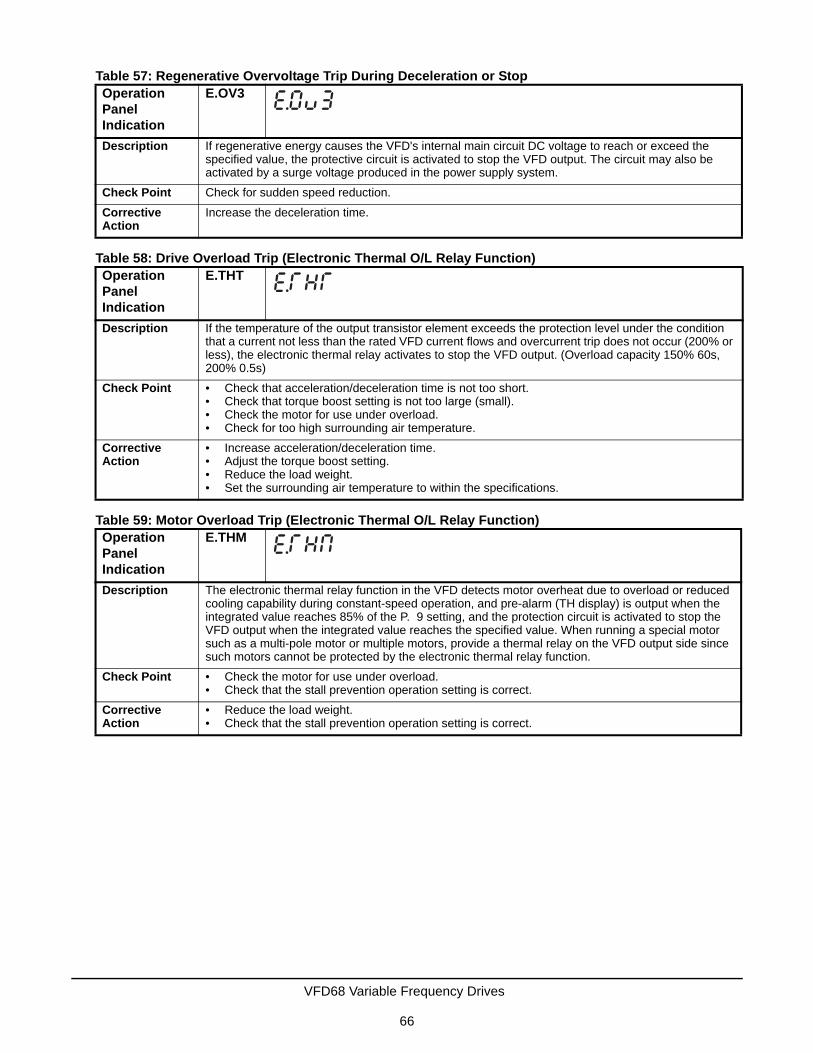
Table 57: Regenerative Overvoltage Trip During Deceleration or StopOperation Panel Indication
E.OV3
Description If regenerative energy causes the VFD's internal main circuit DC voltage to reach or exceed the specified value, the protective circuit is activated to stop the VFD output. The circuit may also be activated by a surge voltage produced in the power supply system.
Check Point Check for sudden speed reduction.
Corrective Action
Increase the deceleration time.
Table 58: Drive Overload Trip (Electronic Thermal O/L Relay Function)Operation Panel Indication
E.THT
Description If the temperature of the output transistor element exceeds the protection level under the condition that a current not less than the rated VFD current flows and overcurrent trip does not occur (200% or less), the electronic thermal relay activates to stop the VFD output. (Overload capacity 150% 60s, 200% 0.5s)
Check Point • Check that acceleration/deceleration time is not too short.• Check that torque boost setting is not too large (small).• Check the motor for use under overload.• Check for too high surrounding air temperature.
Corrective Action
• Increase acceleration/deceleration time.• Adjust the torque boost setting.• Reduce the load weight.• Set the surrounding air temperature to within the specifications.
Table 59: Motor Overload Trip (Electronic Thermal O/L Relay Function)Operation Panel Indication
E.THM
Description The electronic thermal relay function in the VFD detects motor overheat due to overload or reduced cooling capability during constant-speed operation, and pre-alarm (TH display) is output when the integrated value reaches 85% of the P. 9 setting, and the protection circuit is activated to stop the VFD output when the integrated value reaches the specified value. When running a special motor such as a multi-pole motor or multiple motors, provide a thermal relay on the VFD output side since such motors cannot be protected by the electronic thermal relay function.
Check Point • Check the motor for use under overload.• Check that the stall prevention operation setting is correct.
Corrective Action
• Reduce the load weight.• Check that the stall prevention operation setting is correct.
VFD68 Variable Frequency Drives
66

Table 60: Heatsink OverheatOperation Panel Indication
E.FIN
Description If the heatsink overheats, the temperature sensor is actuated and the VFD trips.The FIN signal can be output when the temperature becomes approximately 85% of the heatsink overheat protection operation temperature.
Check Point • Check for too high surrounding air temperature.• Check for heatsink clogging.
• Check that the cooling fan is not stopped (Check that is not displayed on the operation panel).
Corrective Action
• Set the surrounding air temperature to within the specifications.• Clean the heatsink.• Replace the cooling fan.
Table 61: Stall Prevention StopOperation Panel Indication
E.OLT
Description If the output frequency has fallen to 1Hz by stall prevention operation and remains for 3 seconds, a fault (E.OLT) appears and the VFD trips. OL appears while stall prevention is being activated.E.OLT may not occur if stall prevention (OL) is activated during output phase loss.
Check Point Check the motor for use under overload.
Corrective Action
Reduce the load weight. (Check the P. 22 setting.)
Table 62: Brake Transistor Alarm DetectionOperation Panel Indication
E.BE
Description When a brake transistor alarm has occurred due to the large regenerative energy from the motor, the brake transistor alarm is detected and the VFD trips.In this case, the VFD must be powered OFF immediately.
Check Point Reduce the load inertia.
Corrective Action
Replace the VFD.
Table 63: Output Phase LossOperation Panel Indication
E.LF
Description If one of the three phases (U, V, W) on the VFD's output side (load side) is lost during VFD operation (except during DC injection brake operation and when output frequency is under 1Hz), VFD stops the output. Whether the protective function is used or not is set with P.251.
Check Point Check the wiring. (Check that the motor is normal.)Check that the capacity of the motor used is not smaller than that of the VFD.
Corrective Action
Wire the cables properly.Check the P.251 setting.
VFD68 Variable Frequency Drives
67

Table 64: Retry Count ExcessOperation Panel Indication
E.RET
Description If operation cannot be resumed properly within the number of retries set, this function trips the VFD.This function is available only when P. 67 is set to a value other than 0. When P. 67 is set to 0, this protective function does not function. P. 67 is factory-set to 3.
Check Point Find the cause of fault occurrence.
Corrective Action
Eliminate the cause of the error preceding this error indication.
Table 65: CPU FaultOperation Panel Indication
E.5
E.CPU
Description Stops the VFD output if the communication fault of the built-in CPU occurs.
Check Point Check for devices producing excess electrical noises around the VFD.
Corrective Action
Take measures against noises if there are devices producing excess electrical noises around the VFD.Contact PENN by Johnson Controls Application Engineering at 1-414-524-5535 or 1-800-275-5676.
Table 66: Inrush Current Limit Circuit FaultOperation Panel Indication
E.IOH
Description This function is activated when the resistor of the inrush current limit circuit overheats.
Check Point Check that frequent power ON/OFF is not repeated.
Corrective Action
Configure a circuit where frequent power ON/OFF is not repeated.If the problem still persists after taking the above measure, please contact your sales representative.
Table 67: Analog Input FaultOperation Panel Indication
E.AIE
Description Appears if voltage (current) is input to terminal 4 when the setting in P.267 and the setting of the voltage/current input switch are different.
Check Point Check the setting of P.267 and the voltage/current input switch.
Corrective Action
Either give a frequency command by current input or set P.267, and voltage/current input switch to voltage input.
Table 68: Safety Circuit FaultOperation Panel Indication
E.SAF
Description Appears when safety circuit is malfunctioning.Appears when one of the lines between S1 and SC, or between S2 and SC is opened.
Check Point Verify that the jumper wire connects together terminals S1, S2, and SC.
Corrective Action
Connect terminals S1, S2, and SC.
VFD68 Variable Frequency Drives
68

Resetting the VFD68 Drive
If the motor stops due to a fault, you can reset the VFD by using either of the following two methods.
Reset Option 1
1. Remove the jumper that connects terminal SD to terminal STF before clearing the reset.
2. Using the operation panel, press to reset the VFD.
3. Go to Restarting the Motor After It Has Stopped.
Reset Option 2
1. Remove the jumper that connects terminal SD to terminal STF before clearing the reset.
2. Disconnect power from the drive. After the indicator of the operation panel turns OFF, reinstall the jumper that connects terminal SD to terminal STF.
3. Reconnect power to the drive.
Manually Stopping the Motor
You can stop the motor while the VFD68 drive is in any mode (PU, EXT, or NET) by pressing . When you
press , the drive monitor displays PS (PU Stop Warning) and then performs a controlled shutdown of the
motor.
!WARNING: Risk of Personal Injury.Before you reset the VFD68 drive, verify that all persons are clear of the controlled equipment. Resetting the VFD68 drive may immediately start the controlled equipment, and failure to verify that all persons are clear of the controlled equipment before resetting the VFD68 drive may result in severe personal injury or death.
AVERTISSEMENT: Risque de blessure.Avant de réinitialiser le VFD68 drive, assurez-vous qu'aucune personne n'est à proximité de l'équipement. La réinitialisation du VFD68 drive peut faire redémarrer l'équipement contrôlé immédiatement et le non-respect de cette précaution pourrait entraîner des blessures graves, voire mortelles.
IMPORTANT: To prevent the motor from starting immediately after a fault reset, remove the jumper that connects terminal SD to terminal STF before clearing the reset.
STOPRESETSTOP
RESET
STOPRESETSTOP
RESET
STOPRESETSTOP
RESET
VFD68 Variable Frequency Drives
69

Restarting the Motor After It Has Stopped
VFD68Bxx and VFD68Cxx Drives
To restart the motor after a controlled stop, disconnect the supply power from the drive for at least 30 seconds and then reconnect the supply power to the drive.
If it is not easy to disconnect the supply power from the drive, follow these steps:
1. Disconnect the jumper between the SD and STF terminals on the low-voltage terminal blocks.
2. Press . The PU LED lights.
3. Press two more times. The EXT LED lights.
4. Reconnect the jumper between the SD and STF terminals.
VFD68Dxx Drives
To restart the motor after a controlled stop, disconnect the supply power from the drive for at least 30 seconds and then reconnect the supply power to the drive.
If it is not easy to disconnect the supply power from the drive, follow these steps:
1. Disconnect the jumper between the SD and STF terminals on the low-voltage terminal blocks.
2. Verify that the SINK/SOURCE jumper to the left of the low-voltage terminal blocks (Figure 22) is set to SINK.
3. Press until PU PU appears on the display.
4. Press until OP.nd EXT appears on the display.
5. Press until 0.00 MON EXT appears on the display.
6. Reconnect the jumper between the SD and STF terminals.
The VFD68 is now commissioned, is in the external operation mode, and is ready to run the motor using the analog inputs.
7. Press to return to monitor mode. 0.00 MON PU appears on the screen.
PUEXT
PUEXT
MODE
MODE
MODE
VFD68 Variable Frequency Drives
70

Advanced TroubleshootingUse the following tables to resolve problems with the VFD68 drive.
Table 69: Symptoms and ResolutionsSymptom Resolution Table
Motor Does Not Start Table 70 on page 72
Motor or Machine Makes Generates Acoustic Noise Table 71 on page 73
VFD Generates Abnormal Acoustic Noise Table 72 on page 73
Motor Generates Heat Abnormally Table 73 on page 73
Motor Rotates in the Opposite Direction Table 74 on page 73
Speed Greatly Differs from the Setting Table 75 on page 74
Acceleration/Deceleration Is Not Smooth Table 76 on page 74
Speed Varies During Operation Table 77 on page 74
Operation Mode Cannot Be Changed Table 78 on page 74
Operation Panel Display Does Not Operate Table 79 on page 74
Motor Current is Too Large Table 80 on page 75
Unable to Write Parameter Setting Table 81 on page 75
VFD68 Variable Frequency Drives
71

Table 70: Motor Does Not StartCheck
Points
Possible Cause Action
Main Circuit
Appropriate power supply voltage is not applied.(Operation panel display is not provided.)
Power ON moulded case circuit breaker (MCCB), an earth leakage circuit breaker (ELB), or a magnetic contactor (MC).
Check for the proper input voltage, input phase loss, and wiring.
Motor is not connected properly. Check the wiring between the VFD and the motor.
The jumper from terminal P/+ to terminal P1 (on VFD68Bxx and VFD68Cxx models) or from terminal P to terminal P1 (on VFD68Dxx models) has been removed.
Connect a jumper from terminal P/+ or terminal P to terminal P1.
Input Signal
Analog input signal is not enough to start the motor.
Check for proper voltage on analog inputs.Verify that the PU and EXT LEDs are illuminated.
Terminal STR is connected to terminal SD. Disable the STR feature by setting P. 78 = 1. Connect terminal SD to terminal STF to run the motor in the forward direction.
Frequency command is zero.(RUN LED on the operation panel is flickering.)
Check the frequency command source and enter a frequency command.
SINK-SOURCE jumper is set incorrectly.(RUN LED on the operation panel is flickering.)
Check that the control logic switchover jumper connector is installed in the SINK position:• VFD68Bxx and VFD68Cxx: Figure 20 on page 29• VFD68Dxx: Figure 22 on page 31If it is not installed correctly, input signal is not recognized.
Jumper wires between S1 and SC, S2 and SC are disconnected (VFD68Bxx and VFD68Cxx models only).
Verify that jumper wires connect together terminals S1, S2, and SC.
Voltage/current input switch is not correctly set for analog input signal (0 to 5 V or 0 to 10 V, 4 to 20 mA) (VFD68Bxx and VFD68Cxx models only).(RUN LED on the operation panel is flickering.)
Set P. 73, P.266, P.267, and a voltage/current input switch correctly, then input an analog signal in accordance with the setting.
Param.
Setting
Motor Speed vs. Pressure (C 2 to C 7) settings are improper.
Check the Motor Speed vs. Pressure (C 2 to C 7) calculations and settings.
Load Load is too heavy. Reduce the load.
Shaft is locked. Inspect the machine (motor).
Others Operation panel display shows an error (E.OC1). When any fault occurs, take an appropriate corrective action, then reset the VFD, and resume the operation.
VFD68 Variable Frequency Drives
72

Table 71: Motor or Machine Generates Abnormal Acoustic Noise Check
Points
Possible Cause Action
Param. Setting
Resonance occurs (mechanical system resonance frequency)
• For Frequency Jump 2, set P. 33 and P. 34.• For Frequency Jump 3, set P. 35 and P. 36When it is desired to avoid resonance attributable to the natural frequency of a mechanical system, these parameters allow resonant frequencies to be jumped.
Resonance occurs (carrier frequency) Change P. 72 setting.Changing the PWM carrier frequency can reduce the audible noise created when the motor is running at speeds slower than the maximum rated speed (see PWM Frequency, Audible Motor Noise, and EMI on page 52).
Others Mechanical looseness Adjust machine/equipment so that there is no mechanical looseness.
Motor Operating with output phase loss Check the motor wiring. Contact the motor manufacturer.
Table 72: VFD Generates Abnormal Acoustic NoiseCheck
Points
Possible Cause Action
Fan The fan cover was not correctly installed when a cooling fan was replaced.
Install the fan cover correctly.
Table 73: Motor Generates Heat AbnormallyCheck
Points
Possible Cause Action
Param. Setting
The fan motor is running too slowly to create airflow.
Verify that P. 31 is set to 0 and P. 32 is set to 12.5 Hz. If 12.5 Hz is too slow, increase frequency for• P.32, C 2, C 5 (VFD68Bxx and VFD68Cxx
models)• P.32, P.902a, P.904a (VFD68Dxx models).
Motor The fan motor is not working (dust is accumulating.)
Clean the motor fan.Improve the environment.
Phase to phase insulation of the motor is insufficient.
Check the insulation of the motor.
Main Circuit
The VFD output voltage (U, V, W) are unbalanced.
Check the output voltage of the VFD.Check the insulation of the motor.
Table 74: Motor Rotates in the Opposite DirectionCheck
Points
Possible Cause Action
Main Circuit
Phase sequence of output terminals U, V and W is incorrect.
Connect phase sequence of the output cables (terminals U, V, W) to the motor correctly
VFD68 Variable Frequency Drives
73

Table 75: Speed Greatly Differs From the SettingCheck
Points
Possible Cause Action
Input Signal
Analog input device is not creating the proper analog signal.
Measure the input signal level.
The analog input signal lines are affected by external EMI.
Use shielded wire for the low-voltage analog inputs and route the wiring away from high-voltage wiring. Connect shields to VFD terminal 5. If EMI still affects the control or the VFD, then install a ferrite core (such as TDK P/N: ZCAT3035-1330) on the analog input wiring.
Param. Setting
Torque Boost or Maximum Speed settings are improper.
Check the settings of P. 1 and P. 2.
Motor Speed versus Pressure Ramp settings are improper.
VFD68Bxx and VFD68 Cxx: Check the C 2 to C 7 settings.VFD68Dxx: Check the P.905 to P.905 settings.
P. 32 setting is incorrect. Determine the best minimum motor speed needed before the motor shuts off and use that value for P. 32.
Table 76: Acceleration/Deceleration is not SmoothCheck
Points
Possible Cause Action
Param. Setting
Acceleration/deceleration time is too short or too long.
Change P. 7 and P. 8 values.
Table 77: Speed Varies During OperationCheck
points
Possible Cause Action
Input signal
The analog input signal lines are affected by EMI.
Use shielded wires for the low-voltage analog input signal lines. Route the wiring away from high-voltage wiring. Connect shields to VFD terminal 5. If EMI still affects the control or the VFD, then install a ferrite core (such as TDK P/N: ZCAT3035-1330) on the analog input wiring.
Param. Setting
The power supply voltage fluctuates too much. Change the P. 19 setting to the voltage rating on the controlled motor.
Table 78: Operation Mode Cannot Be ChangedCheck
Points
Possible Cause Action
Input Signal
Start signal is enabled (terminal STF is connected to terminal SD).
Check that a jumper is not connecting the STF and SD terminals. If the jumper is connected, the operation mode cannot be changed.
Table 79: Operation Panel Display MalfunctionsCheck
Points
Possible Cause Action
Display The operation panel display malfunctions. Contact PENN by Johnson Controls Application Engineering at 1-414-524-5535 or 1-800-275-5676.
VFD68 Variable Frequency Drives
74

Table 80: Motor Current is Too LargeCheck
Points
Possible Cause Action
Load The fan motor stalls and error code OL appears on the display.
Ensure that combination of motors connected in parallel does not exceed the VFD68 drive’s output current rating.
Table 81: Unable to Write Parameter SettingCheck
Points
Possible Cause Action
Input Signal
P. 77 should be set to 2. Verify that P.77 is set to 2.
Param. Setting
P.296 and P.297 may be set for Password Lock. Check with your local equipment supervisor to verify the Password Lock restriction level.
VFD68 Variable Frequency Drives
75

Technical SpecificationsVFD68Bxx or VFD68Cxx Variable Frequency Drive (230 or 460 VAC)
Input Power Voltage/Frequency
230 VAC, 50 HZ (208/230 VAC, 60 Hz);400 VAC, 50 Hz (460 VAC, 60 Hz);Continuous Duty
Output Voltage/Frequency 230 VAC, 50 HZ (208/230 VAC, 60 Hz);400 VAC, 50 Hz (460 VAC, 60 Hz);Continuous Duty
Input Devices Johnson Controls/PENN® P499 Electronic Pressure Transducers
PWM Carrier Frequency Adjustable 0.7 to 15 kHz
Motor Requirements Three-phase NEMA Design B motors required; Inverter-rated motors recommended
Overload Capacity 150% of ampere rating for 1 minute
Start/Stop Use STF input to start or stop the motor
Ambient Conditions Storage: -40 to 65ºC (-40 to 149ºF), 0 to 95% RH noncondensing
Operating: -40 to 50ºC (-40 to 122ºF), 0 to 95% RH noncondensing
Altitude: 1,000 m (3,300 ft) Maximum without derating
Enclosures UL Type 1 (NEMA) Fan Cooled (230 VAC 1 hp and lower models do not have a fan)
Maximum High Voltage Wire Length
Up to 100 m (328 ft) between the VFD68 drive and the motor (using the appropriate wire gauge)
Compliance North America: cULus Listed, UL 508C, CSA-C22.2 No. 14, File E244421;Industry Canada (IC) Compliant to Canadian ICES-003, Class B limitsEurope: CE Mark - Johnson Controls, Inc. declares that this product is in compliance with the essential requirements and other relevant provisions of the Low Voltage Directive and the EMC Directive when an EMC-compliant line filter is attached to the power supply.1 Australia: Regulatory Compliance Mark (RCM)
1. For more information, see Appendix 5: EMC Line Filter Selection Chart on page 107.
Dimensions (H x W x D) Minimum: 128 x 68 x 81 mm (5 x 2-11/16 x 3-3/16 in.) Maximum: 150 x 140 x 136 mm (5-15/16 x 5-1/2 x 5-5/16 in.)
Shipping Weight 230 VAC ±10% Production Models:VFD68BBB, VFD68BCB: 0.5 kg (1.1 lb)VFD68BDC: 0.8 kg (1.8 lb)VFD68BFD: 1.0 kg (2.2 lb)VFD68BGG, VFD68BHG: 1.4 kg (3.1 lb)VFD68BJK: 1.8 kg (4.0 lb)VFD68BKL, VFD68BLL: 3.6 kg (8.0 lb)VFD68BMP, VFD68BNP: 6.5 kg (14.3 lb)
460 VAC ±10% Production Models:VFD68CDF, VFD68CFF: 1.3 kg (2.9 lb)VFD68CGG: 1.4 kg (3.1 lb)VFD68CHH, VFD68CJJ: 1.5 kg (3.3 lb)VFD68CKL, VFD68CLL: 3.3 kg (7.3 lb)VFD68CMP, VFD68CNP: 6.5 kg (14.3 lb)
VFD68Dxx Variable Frequency Drive (575 VAC) (Part 1 of 2)Input Power Voltage/Frequency
575 VAC, 50 Hz;Continuous Duty
Output Voltage/Frequency 575 VAC, 50 Hz;Continuous Duty
Input Devices Johnson Controls/PENN® P499 Electronic Pressure Transducers
VFD68 Variable Frequency Drives
76

PWM Carrier Frequency Adjustable 0.7 to 15 kHz
Motor Requirements Three-phase NEMA Design B motors required; Inverter-rated motors recommended
Overload Capacity 150% of ampere rating for 1 minute
Start/Stop Use STF input to start or stop the motor
Ambient Conditions Storage: -40 to 65ºC (-40 to 149ºF), 0 to 95% RH Non-condensing
Operating: -40 to 50ºC (-40 to 122ºF), 0 to 95% RH Non-condensing
Altitude: 1,000 m (3,300 ft) Maximum without derating
Enclosures UL Type 1 (NEMA) Fan Cooled
Maximum High-Voltage Wire Length
Up to 100 m (328 ft) between the VFD68 drive and the motor (using the appropriate wire gauge)
Compliance North America: cULus Listed, UL 508C, CSA-C22.2 No. 14, File E244421;
Dimensions (H x W x D) Minimum: 150 x 140 x 136 mm (5-15/16 x 5-1/2 x 5-5/16 in.)Maximum: 150 x 220 x 148 mm (5-15/16 x 8-11/16 x 5-13/16 in.)
Shipping Weight 575 VAC +5/-10% Production Models:VFD68DFM: 1.8 kg (3.96 lb)VFD68DGM, VFD68DHM: 2.0 kg (4.41 lb)VFD68DJN, VFD68DKN, VFD68DLN: 3.8 kg (8.38 lb)
VFD68Dxx Variable Frequency Drive (575 VAC) (Part 2 of 2)
VFD68 Variable Frequency Drives
77
Appendix 1: Check Fault HistoryThe last eight Fault, Error, or Warning indicator messages are stored in the VFD. To view these messages, use the following procedure and see Figure 40 on page 79:
1. Power the VFD and set it to the MON mode (MON LED is on).
2. Press the MODE button twice to enter Fault History mode (E---).
3. Rotate the setting dial slightly.
• If an Indicator Fault, Error, or Warning has occurred, the display blinks while showing an indicator message.
• If no Fault, Error, or Warning has occurred, the display shows E 0.
4. Press the setting dial to view the actual indicator message number (message number 1 is the most recent).
5. Rotate the setting dial to view all eight indicator messages.
To exit the Fault History Mode, press the MODE button until the MON LED is on.
VFD68 Variable Frequency Drives
78

Figure 40: Check Fault History
VFD68 Variable Frequency Drives
79

Appendix 2: Additional VFD68 Drive Application Examples
VFD68Bxx and VFD68Cxx Drives
PL = 262 PSI; PH = 420 PSI; C 3, C 4, C 6, and C 7 use default settings.
Figure 41: Connecting Two Ratiometric Transducers
Figure 42: Motor Speed versus Pressure Ramp for 0–750 PSI Transducer
VFD68 Variable Frequency Drives
80

Figure 43: Motor Speed versus Pressure Ramp for 0–50 PSI Transducer Used in a Reverse Acting Mode (RA Mode)
VFD68 Variable Frequency Drives
81

PL = 170 PSI; PH = 260 PSI; Calculate new values for C 3 and C 4. When connecting a second P499V transducer, then also change Parameter C 6 to 3.4V and change C 7 to 5.2V.
Figure 44: Connecting Two 0–10V Output Transducers
Figure 45: Motor Speed versus Pressure Ramp for 0–500 PSI Transducer
VFD68 Variable Frequency Drives
82

PL = 135 PSI; PH = 219 PSI; Calculate new values for C 6 and C 7.
Figure 46: Connecting One 4–20 mA Output Transducer
Figure 47: Motor Speed versus Pressure Ramp for 0–500 PSI 4–20 mA Transducer
VFD68 Variable Frequency Drives
83
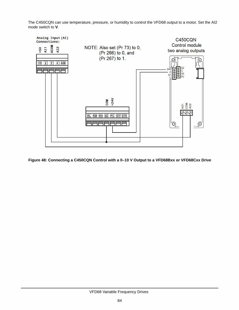
The C450CQN can use temperature, pressure, or humidity to control the VFD68 output to a motor. Set the AI2 mode switch to V.
Figure 48: Connecting a C450CQN Control with a 0–10 V Output to a VFD68Bxx or VFD68Cxx Drive
VFD68 Variable Frequency Drives
84
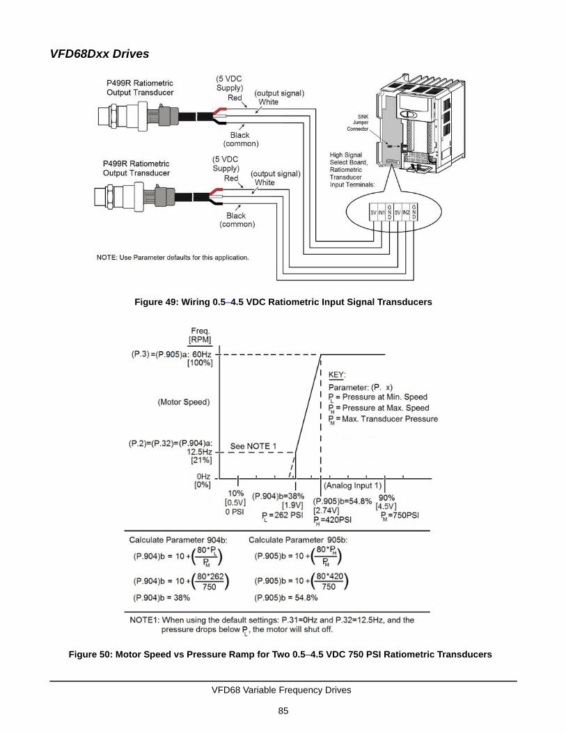
VFD68Dxx Drives
Figure 49: Wiring 0.5–4.5 VDC Ratiometric Input Signal Transducers
Figure 50: Motor Speed vs Pressure Ramp for Two 0.5–4.5 VDC 750 PSI Ratiometric Transducers
VFD68 Variable Frequency Drives
85

Figure 51: Wiring 0–10 V Input Signal Transducer
Figure 52: Motor Speed vs Pressure Ramp for 0–10 VDC 500 PSI Transducer
VFD68 Variable Frequency Drives
86

Figure 53: Wiring 4–20 mA Input Signal Transducer
Figure 54: Motor Speed vs Pressure Ramp for 4–20 mA 500 PSI Transducer
VFD68 Variable Frequency Drives
87

Appendix 3: Password Functions (P.296, P.297)Registering a four-digit password can restrict parameter reading and writing. You can set these parameters when P.160 = 0.
Note: When P.296 is set to something other than 9999, then P.297 is always available to enter a password, regardless of the setting for P.160.
Parameter Reading and Writing Restriction LevelP.296 controls the level of reading and writing restriction.
Table 82: Implement Password ProtectionParameter Name Default Range Description
P.296 Password Lock Level 9999 1 to 6, 101 to 106 Select the restriction level of parameter reading and writing when a password is required.
9999 No password lock
P.297 Password Unlock/Lock
9999 1000 to 9998 Register a four-digit password
(0) (reading only)Valid when P.296 = 1 to 6
(0 to 5) Displays password unlock error count (reading only)Valid when P.296 = 101 to 106
(9999) No password lock (reading only)
Table 83: Parameter Reading and Writing Restriction (P.296)P.296 Setting PU Operation Mode Command1
1. Parameter access from a unit where the parameter is written in the PU Manual Operation mode is restricted.
NET Mode Operation Command2
2. Parameter access in NET Operation mode with RS-485 communication is restricted.
Read3
3. If the parameter reading is restricted by P.160, P.296 is unavailable for reading, even when enabled.
Write4
4. If the parameter writing is restricted by P.77, P.296 is unavailable for writing, even when enabled.
Read3 Write4
9999 Enabled Enabled Enabled Enabled
1, 101 Enabled Restricted Enabled Restricted
2, 102 Enabled Restricted Enabled Enabled
3, 103 Enabled Enabled Enabled Restricted
4, 104 Restricted Restricted Restricted Restricted
5, 105 Restricted Restricted Enabled Enabled
6, 106 Enabled Enabled Restricted Restricted
VFD68 Variable Frequency Drives
88

Password Lock and Unlock
Lock
1. Set the parameter restriction level as shown in Table 84.
2. Enter a four-digit number (1000 to 9998) as a password.
• When a password is registered, parameter reading and writing is restricted with the restriction level set in P.297 until unlocking.
• After registering a password, a read value of P.297 is always 0 to 5.
• When a password-restricted parameter is read or written, LOCd appears on the display.
• Even if a password is registered, parameters that the VFD itself writes, such as VFD Parts Life, are overwritten occasionally.
Unlock
You can unlock the password one of two ways:
• enter a password in P.297
• perform a parameter all clear (see Perform a Parameter All Clear on page 89.)
Enter a Password in P.297
Entering a correct password in P.297 unlocks the VFD and sets P. 297 back to 9999 (no password lock). You must enter a setting from 1000 to 9998 again for this parameter to register a new 4-digit password. Entering an incorrect password:
• (when P.296 = 1 to 6) creates a password unlock error, but does not lock the VFD. If the correct password is eventually entered, the VFD68 will unlock.
• (when P.296 = 101 to 106) creates a password unlock error.
Note: If the password unlock error has occurred five times, the VFD password function locks, and you must perform a Parameter All Clear to unlock the restriction (see Perform a Parameter All Clear on page 89). Entering the correct password after the fifth incorrect entry has no effect.
Perform a Parameter All Clear
• If you forgot the password, perform a parameter all clear to unlock the parameter restriction.
Note: When you perform a parameter all clear, all parameters are restored to the default values.
• Parameter all clear cannot be performed while the VFD has an active voltage output.
Table 84: Set Password Restriction Level (P.296)P.296 Setting Restriction of Password Unlock
ErrorP.297 Display
1 to 6 No restriction Always 0
101 to 106 Restricted at fifth error1
1. If the password unlock error has occurred five times, see Perform a Parameter All Clear to unlock the restriction. Entering the correct password after the fifth incorrect entry has no effect.
Displays error count (0 to 5)
VFD68 Variable Frequency Drives
89

Appendix 4: VFD68Bxx and VFD68Cxx ModBus RTU RS485 Communications Bus Specifications
You must create a custom RS485 communication cable to connect the VFD68Bxx or VFD68Cxx to the head end of a ModBus RTU network.
IMPORTANT: Do not connect pin 2 or pin 8 to a communication cable. Pin 2 and pin 8 of the RJ45 receptacle are connected to a power supply in the VFD68 drive. Connecting one or both of these pins to a communication cable may damage the VFD68 drive.
Table 85: VFD68Bxx and VFD68Cxx RJ45 Pin Identifications for Communications BusPin Number Name Description
1 SG Earth (ground) (connected to terminal 5)
2 — Power supply
3 RDA VFD receive (+)
4 SDB VFD send (-)
5 SDA VFD receive (+)
6 RDB VFD send (-)
7 SG Earth (ground) (connected to terminal 5)
8 — Power supply
Figure 55: VFD68Bxx and VFD68Cxx Identification of RJ45 Receptacle
VFD68 Variable Frequency Drives
90
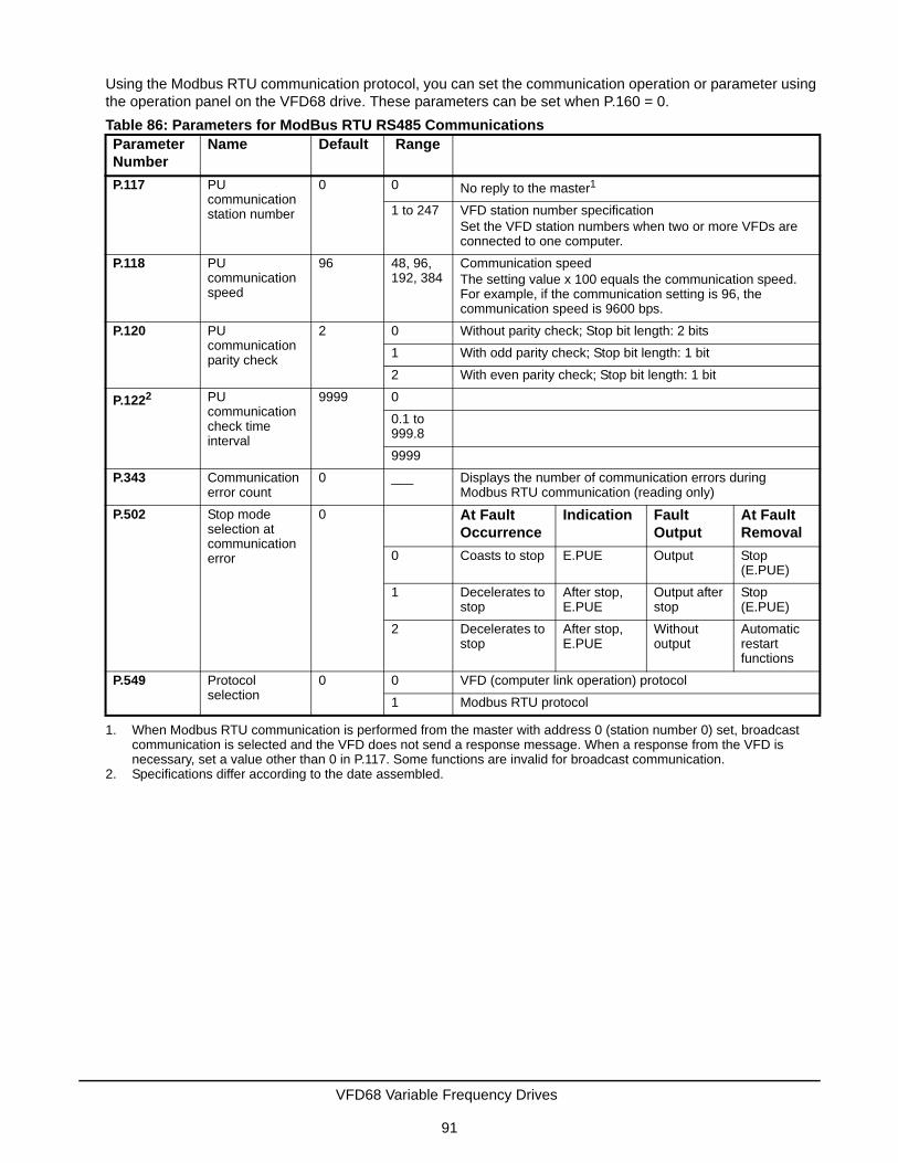
Using the Modbus RTU communication protocol, you can set the communication operation or parameter using the operation panel on the VFD68 drive. These parameters can be set when P.160 = 0.
Table 86: Parameters for ModBus RTU RS485 CommunicationsParameter Number
Name Default Range
P.117 PU communication station number
0 0 No reply to the master1
1. When Modbus RTU communication is performed from the master with address 0 (station number 0) set, broadcast communication is selected and the VFD does not send a response message. When a response from the VFD is necessary, set a value other than 0 in P.117. Some functions are invalid for broadcast communication.
1 to 247 VFD station number specificationSet the VFD station numbers when two or more VFDs are connected to one computer.
P.118 PU communication speed
96 48, 96, 192, 384
Communication speedThe setting value x 100 equals the communication speed. For example, if the communication setting is 96, the communication speed is 9600 bps.
P.120 PU communication parity check
2 0 Without parity check; Stop bit length: 2 bits
1 With odd parity check; Stop bit length: 1 bit
2 With even parity check; Stop bit length: 1 bit
P.1222
2. Specifications differ according to the date assembled.
PU communication check time interval
9999 0
0.1 to 999.8
9999
P.343 Communication error count
0 ___ Displays the number of communication errors during Modbus RTU communication (reading only)
P.502 Stop mode selection at communication error
0 At Fault Occurrence
Indication Fault Output
At Fault Removal
0 Coasts to stop E.PUE Output Stop (E.PUE)
1 Decelerates to stop
After stop, E.PUE
Output after stop
Stop (E.PUE)
2 Decelerates to stop
After stop, E.PUE
Without output
Automatic restart functions
P.549 Protocol selection
0 0 VFD (computer link operation) protocol
1 Modbus RTU protocol
VFD68 Variable Frequency Drives
91

Communication Specification
OutlineThe Modbus protocol performs serial communication between the master and slave (VFD) using the dedicated message frame. The dedicated message frame has functions that can read and write data. Using these functions, you can:
• read and write the parameter values from the VFD
• write the input commend of the VFD
• check the operating status
The master communicates with the slave (VFD) by accessing the assigned holding register address.
Note: There are two different serial transmission modes: ASCII (American Standard Code for Information Interchange) and RTU (Remote Terminal Unit) mode. This product supports only the RTU mode, in which 1-byte (8-bit) data is transmitted as it is. Only the communication protocol is defined by the Modbus protocol - the physical layer is not stipulated.
Table 87: Communication SpecificationItem Description Related
Parameter
Communication Protocol Modbus RTU protocol P.549
Conforming Standard EIA-485 (RS-485) —
Number of Connectable Devices 1:N (maximum 32 units), setting is 0 to 247 stations P.117
Communication Speed Select 4800, 9600, 19200, or 38400 bps P.118
Control Procedure Asynchronous —
Communication Method Half-duplex —
Communication Character System Binary (always 8 bits) —
Start Bit 1 bit —
Stop Bit Length • No parity, stop bit length: 2 bits• Odd Parity; stop bit length: 1 bit• Even parity; stop bit length: 1 bit
P.120
Parity Check
Error Check CRC code check —
Terminator Not used —
Waiting Time Setting Not used —
VFD68 Variable Frequency Drives
92

Message Format
Query
The master sends a message to the slave (VFD) at the specified address.
Normal Response
After receiving the query from the master, the slave executes the requested function and returns the corresponding normal response to the master.
Error Response
If an invalid function code, address, or data is received, the slave returns it to the master. When a response description is returned, the error code indicating that the request from the master cannot be executed is added. No response is returned for the hardware-detected error, frame error, and CRC check error.
Broadcast
By specifying address 0, the master can send a message to all slaves. All slaves that received the message from the master execute the requested function. In this communication, the slaves do not return a response to the master.
Note: The VFD performs the function independently of the VFD station number setting (P.117) during broadcast communication.
Table 88: Data Check TimeItem Check Time
Various Monitors, Operation Command, Frequency Setting (RAM) < 20 ms
Parameter Read and Write, Frequency Setting (EEPROM) < 50 ms
Parameter Clear or All Clear < 5 s
Reset Command No answer
Broadcast Communication
Master (programmable controller)
Slave (VFD)
Query Message
No Response
Query Communication
Master (programmable controller)
Slave (VFD)
Query Message
Response MessageData Absence Time(3.5 bytes or more)
VFD Response Time(Data Check Time)
Figure 56: Message Format
VFD68 Variable Frequency Drives
93

Message Frame (Protocol)
Communication Method
The master sends a query message (question), and the slave returns a response message (response). When communication is normal, Device Address and Function Code are copied. When communication is abnormal (function code or data code is illegal), bit 7 (=80H) of Function Code is turned on, and the error code is set to Data Bytes.
The message frame consists of the four message fields as shown in Figure 57. By adding the no-data time (T1: Start, End) of 3.5 characters to the beginning and end of the message data, the slave recognizes it as one message.
Protocol Details
Table 89: Summary of Message FieldsStart 1 2 3 4 End
Address Function Data CRC Check
T1 8 bit 8 bit n x 8 bit L 8 bit H 8 bit T1
Table 90: Description of Message Fields (Part 1 of 2)Message Field
Description
Address The address code is 1 byte long (8 bits) and any address from 0 to 247 can be set. Set 0 to send a broadcast message (all-address instruction) or any of 1 to 247 to send a message to each slave.When the slave responds, it returns the address set from the master.The value of P.117 is the slave address.
Device Address
Function Code
Eight-BitData Bytes
Error Check
Device Address
Function Code
Eight-BitData Bytes
Error Check
Query Messagefrom Master
Response Messagefrom Slave
Figure 57: Communication Message Structure
VFD68 Variable Frequency Drives
94

Function The function code is 1 byte (8 bits) and any address from 0 to 247 can be set. The master sets the function that it wants to request to the slave, and the slave performs the requested operation.See the sub-table for the supported function codes.
Code Function Name Outline Broadcast Communication
H03 Read Holding Register Reads the holding register data
Not Allowed
H06 Present Single Register Writes data to the holding register
Allowed
H08 Diagnostics Function diagnosis (communication check only)
Not Allowed
H10 Present Multiple Register Writes data to multiple consecutive holding registers
Allowed
H46 Read Holding Register Access Log Reads the number of registers that succeeded in communication last time
Not Allowed
• If the set function code is other than the ones listed in this sub-table, the slave returns an error response.
• When the slave returns a normal response, it returns the function code set by the master.• When the slave returns an error response, it returns H80 + function code.
Data The format changes depending on the function code. Data includes the byte count, number of bytes, description of the access to the holding register, and similar information.
CRC Check The message frame is checked for error by creating a CRC number. This two-byte long CRC data is added to the end of the message. When CRC is added to the message, the low-order byte is added first and is followed by the high-order byte.The CRC value is calculated by the master and is added to the master message. The slave recalculates the CRC after the message is received and compares it with the value received in the message. If these values do not match, then the slave flags this message as containing an error and discards the message.
Table 90: Description of Message Fields (Part 2 of 2)Message Field
Description
VFD68 Variable Frequency Drives
95

Message Format Types
Read Holding Register Data (H03 or 03)
Can read the description of the following items:
1. system environment variables
2. real-time monitor
3. fault history
4. VFD parameters assigned to the holding register area
Table 91: Query MessageSlave Address
Function Starting Address Number of Points CRC Check
(8 bit) H03 (8 bit) H (8 bit) L (8 bit) H (8 bit) L (8 bit) L (8 bit) H (8 bit)
Table 92: Normal Response MessageSlave Address
Function Byte Count
Data CRC Check
(8 bit) H03 (8 bit) (8 bit) H (8 bit) L (8 bit) ... (n x 16 bit)
L (8 bit) H (8 bit)
Table 93: Query Message DescriptionMessage Description
Slave Address Address to which the message is sent. Broadcast communication cannot be made (0 is invalid).
Function Set H03
Starting Address Set the address at which holding register data read is startedStarting address = starting register address (decimal)-40001For example, setting the starting address 0001 reads the data of the holding register 40002.
Number of Points Number of holding registers from which the data is read (125 maximum).
Table 94: Normal Response Message DescriptionMessage Description
Byte Count The setting range is H02 to H14 (2 to 20). The byte count is set at twice the number of points.
Data: Read Data The number of data to be read equals the number of points. Data are read in order of high byte and low byte, and set in order of starting address data, starting address+1 data, starting address +2 data, and so forth.
VFD68 Variable Frequency Drives
96

Example
The following tables contain a query message directed to the VFD68 slave address 17 (H11). This message requests a read of register addresses (parameter values) 41004 (P.4) to 41006 (P.6). These tables also show the VFD68 slave response message containing the 2 byte Parameter Values P. 4, P. 5, and P. 6 (Table 95 and Table 96).
Register Starting Address: H03 HEB = 1003 decimal. A base number of 40001 decimal must be added to this Register Starting Address to achieve the Register number of: 41004 decimal for Parameter 4 (see Table 120).
Read value
Register 41004 (P.004); H1770 (60.00 Hz)
Register 41005 (P.005); H0BB8 (30.00 Hz)
Register 41006 (P.006); H03E8 (10.00 Hz)
Table 95: Query MessageSlave Address
Function Starting Address Number of Points CRC Check
H11 (8 bit) H03 (8 bit) H03 (8 bit) HEB (8 bit) H00 (8 bit) H03 (8 bit) H77 (8 bit) H2B (8 bit)
Table 96: Normal Response (Response Message)Slave Address
Function Byte Count
Data CRC Check
H11 (8 bit)
H03 (8 bit)
H06 (8 bit)
H17 (8 bit)
H70 (8 bit)
H0B (8 bit)
HB8 (8 bit)
H03 (8 bit)
HE8 (8 bit)
H2C (8 bit) HE6 (8 bit)
VFD68 Variable Frequency Drives
97

Write Holding Register Data (H06 or 06)
The following tables contain a query message directed to the VFD68 slave instructing a write to a register address (parameter value) using the 2 byte preset data, followed by the VFD68 response message (Table 97 through Table 100).
Example
The following tables contain a query message directed to the VFD68 slave address 5 (H05) instructing a 2 byte preset data write a value of 60HZ (H1770) to the running frequency RAM register address (system environment variable) of 40014, followed by the VFD68 response message (Table 101, Table 102).
Note: For broadcast communication, no response is returned in reply to a query; therefore, the next query must be made when the VFD processing time has elapsed after the previous query.
Table 97: Query MessageSlave Address Function Register Address Preset Data CRC Check
(8 bit) H06 (8 bit) H (8 bit) L (8 bit) H (8 bit) L (8 bit) L (8 bit) H (8 bit)
Table 98: Normal Response (Response Message)Slave Address Function Register Address Preset Data CRC Check
(8 bit) H06 (8 bit) H (8 bit) L (8 bit) H (8 bit) L (8 bit) L (8 bit) H (8 bit)
Table 99: Query Message SettingMessage Setting Description
Slave Address Address to which the message will be sent. Setting address to 0 enables broadcast communication.
Function Set H06
Register Address Address of holding register to which data will be writtenRegister address = holding register address (decimal)-40001For example, setting the register address 0001 reads the data of the holding register 40002.
Preset Data Data that will be written to the holding register. The written data is always 2 bytes.
Table 100: Description of Normal Response1
1. Slave address, function, register address, preset data, and CRC check of the normal response are identical to those of the query message. No response is made for broadcast communication.
Message Setting Description
Slave Address Address to which the message is sent. Setting address to 0 enables broadcast communication.
Function Set H06
Register Address Address of holding register to which data is writtenRegister address = holding register address (decimal)-40001For example, setting the register address 0001 reads the data of the holding register 40002.
Preset Data Data that is written to the holding register. The written data is always 2 bytes.
Table 101: Query MessageSlave Address Function Register Address Preset Data CRC Check
H05 (8 bit) H06 (8 bit) H00 (8 bit) H0D (8 bit) H17 (8 bit) H70 (8 bit) H17 (8 bit) H99 (8 bit)
Table 102: Normal Response (Response Message)1
1. Slave address, function, register address, preset data, and CRC check of the normal response are identical to those of the query message. No response is made for broadcast communication.
Slave Address Function Register Address Preset Data CRC Check
H05 (8 bit) H06 (8 bit) H00 (8 bit) H0D (8 bit) H17 (8 bit) H70 (8 bit) H17 (8 bit) H99 (8 bit)
VFD68 Variable Frequency Drives
98

Function Diagnosis (H08 or 08)
A communication check can be made because the query message that was sent is returned unchanged as a response message (function of subfunction code H00).
For broadcast communication, no response is returned in reply to a query; therefore, the next query must be made when the VFD processing time has elapsed after the previous query.
Table 103: Query MessageSlave Address
Function Subfunction Date CRC Check
(8 bit) H08 (8 bit) H00 (8 bit) H00 (8 bit) H (8 bit) L (8 bit) L (8 bit) H (8 bit)
Table 104: Normal Response (Response Message)Slave Address
Function Subfunction Date CRC Check
(8 bit) H08 (8 bit) H00 (8 bit) H00 (8 bit) H (8 bit) L (8 bit) L (8 bit) H (8 bit)
Table 105: Query Message SettingMessage Setting Description
Slave Address Address to which the message is sent. Broadcast communication cannot be made: 0 is an invalid setting.
Function Set H08
Subfunction Set H000
Data Any data can be set if it is 2 bytes long. The setting range is H0000 to HFFFF.
Table 106: Normal Response Message to Query1
1. Slave address, function, subfunction, and CRC check of the normal response are identical to those of the query message.
Message Setting Description
Slave Address Address to which the message is sent. Broadcast communication cannot be made: 0 is an invalid setting.
Function Set H08
Subfunction Set H000
Data Any data can be set if it is 2 bytes long. The setting range is H0000 to HFFFF.
VFD68 Variable Frequency Drives
99

Write Multiple Holding Register Data (H10 or 16)
You can write data to multiple holding registers.
Example
Use the following query message to write 0.5 seconds (H05) to 41007 (P.007) at the slave address 25 (H19) and 1 second (H0A) at 41008 (P.008)
Table 107: Query MessageSlave Address
Function Starting Address
Number of registers
Byte Count
Data CRC Check
(8 bit) H10 (8 bit) H (8 bit)
L (8 bit)
H (8 bit)
L (8 bit)
(8 bit) H (8 bit)
L (8 bit)
...(nx2x8 bit)
L (8 bit)
H (8 bit)
Table 108: Normal Response (Response Message)Slave Address
Function Starting Address Number of registers CRC Check
(8 bit) H10 (8 bit) H (8 bit) L (8 bit) H (8 bit) L (8 bit) L (8 bit) H (8 bit)
Table 109: Query Message Setting1
1. Slave Address, Function, Starting Address, Number of Points, and CRC Check are the same for a normal response as for a query message.
Message Setting Description
Slave Address Address to which the message is sent. 0 enables broadcast communication
Function Set H10
Starting Address Address where holding register data write is started. Starting address = starting register address (decimal)-40001For example, setting the starting address 0001 reads the data of the holding address 40002.
Number of Points Number of holding registers where data is written. The number of registers where data can be written is a maximum of 125.
Byte Count Setting range is H02 to HFA (0 to 250).Set a value twice greater than the value for the number of points.
Data Set the data specified by the number of points. The written data are set in order of high byte and low byte, and arranged in order of the starting address data, starting address +1 data, starting address +2 data, and so forth.
Table 110: Query MessageSlave Address
Function Starting Address
Number of Points
Byte Count
Data CRC Check
H19 (8 bit) H10 (8 bit) H03 (8 bit)
HEE (8 bit)
H00 (8 bit)
H02 (8 bit)
H04 (8 bit)
H00 (8 bit)
H05 (8 bit)
H00(8 bit)
H86 (8 bit)
H3D (8 bit)
Table 111: Normal Response (Response Message)Slave Address
Function Starting Address Number of Points CRC Check
H19(8 bit) H10 (8 bit) H03 (8 bit) HEE (8 bit) H00 (8 bit) H02 (8 bit) H22 (8 bit) H61 (8 bit)
VFD68 Variable Frequency Drives
100

Read Holding Register Access Log (H46 or 70)
A response can be made to a query made by the function code H03 or H10. The starting address of the holding registers that succeed in access during previous communication are returned. Also, the number of successful registers are returned. In response to the query for other than the above function code, 0 is returned for the address and number of registers.
Example
Use the following query message to read the successful register starting address and successful count from the slave address 25 (H19).
Success of two registers at starting address 41007 (P.007) is returned.
Table 112: Query MessageSlave Address Function CRC Check
(8 bit) H46 (8 bit) L (8 bit) H (8 bit)
Table 113: Normal Response (Response Message)Slave Address
Function Starting Address Number of Points CRC Check
(8 bit) H46 (8 bit) H (8 bit) L (8 bit) H (8 bit) L (8 bit) L (8 bit) H (8 bit)
Table 114: Query Message SettingMessage Setting Description
Slave Address Address to which the message is sent. Broadcast communication cannot be made: 0 is an invalid setting.
Function Set H46
Table 115: Normal Response Message to QueryMessage Setting Description
Starting Address The starting address of the holding registers that succeeded is returned. Starting address = starting register address (decimal) - 40001For example, when the starting address 0001 is returned, the address of the holding register that succeeded in access if 40002.
Number of Points The number of holding registers that succeeded in access is returned
Table 116: Query MessageSlave Address Function CRC Check
H19 (8 bit) H46 (8 bit) L (8 bit) H (8 bit)
Table 117: Normal Response (Response Message)Slave Address
Function Starting Address Number of Points CRC Check
H19 (8 bit) H10 (8 bit) H03 (8 bit) HEE (8 bit) H00 (8 bit) H02 (8 bit) H22 (8 bit) H61 (8 bit)
VFD68 Variable Frequency Drives
101

Error Response
An error response is returned if the query message received from the master has an illegal function, address, or data. No response is returned for a parity, CRC, overrun, framing, or busy error.
Note: No response message is sent in the case of broadcast communication.
Note: An error occurs if all accessed holding registers do not exist.
Note: Data read from a nonexistent holding register is 0, and data written there is invalid.
Message Data Mistake Detection
To detect the mistakes of message data from the master, error items are checked for the errors in Table 121. If an error is detected, a trip does not occur.
Table 118: Error Response (Response Message)Slave Address Function Exception Code CRC Check
(8 bit) H80 + function (8 bit) (8 bit) L (8 bit) H (8 bit)
Table 119: Error Response (Response Message)Message Setting Description
Slave Address Address received from the master.
Function Master-requested function code + H80
Exception Code See Table 120.
Table 120: Error Code ListCode Error Item Error Description
01 Illegal Function The set function code in the query message from the master cannot be processed by the slave.
02 Illegal Data Address1
1. An error does not occur in the following cases:a. Function code H03 (Read holding register data) - when the number of points is 1 or more and there is one or more holding registers from which the data may be read.b. Function code H10 (write multiple holding register data) - when the number of points is 1 or more and there is one or more holding registers to which the data may be written.
When the function code H03 or H10 is used to access multiple holding registers, an error does not occur if a nonexistent holding register, read-disabled register, or write-disabled register is accessed.
The set register address in the query message from the master cannot be processed by the slave.
03 Illegal Data Value The set data in the query message from the master cannot be processed by the slave.
Table 121: Message Data Mistake DetectionError Item Error Description VFD Operation
Parity Error The data received by the VFD differs from the specified parity (P.120 setting).
1. P.343 increases by 1 at the error occurrence.
2. The terminal LF is output at an error occurrence.
Framing Error The data received by the VFD differs from the specified slop bit length (P.120).
Overrun Error The following data was sent from the master before the VFD completes receiving data.
Message Frame Error The message frame data length is checked, and the received data length of less than 4 bytes is regarded as an error.
CRC Check Error A mismatch found by CRC Check between the message frame data and calculation result is regarded as an error.
VFD68 Variable Frequency Drives
102

Modbus RegistersTable 122: System Environment VariableRegister Definition Read/Write Remarks
40002 VFD Reset Write Any value can be written.
40003 Parameter Clear Write Set H965A as a written value.
40004 All Parameters Clear Write Set H965A as a written value.
40006 Parameter Clear1
1. The communication parameter values are not cleared.
Write Set H965A as a written value.
40007 All Parameters Clear1 Write Set H965A as a written value.
40009 VFD Status/Control Input Instruction2
2. For write, set data as the control input instruction. For read, data is read as a VFD operating status.
Read/Write See below.2
40010 Operation Mode/VFD Setting3
3. For write, set data as the operation mode setting. For read, data is read as the operation mode status.
Read/Write See below.3
40014 Running Frequency (RAM Value) Read/Write According to the P. 37 settings, the frequency and selectable speed are in 1 rotation/minute increments.40015 Running Frequency (EEPROM Value) Write
Table 123: VFD StatusBit Definition
Control Input Instruction VFD Status
0 Stop command RUN (VFD operational)1
1. The signal within parenthesis is the initial setting. Definitions change according to the settings for P.180 to P182.
1 forward rotation command Forward rotation
2 reverse rotation command During reverse rotation
3 RH (high-speed operation command)2
2. The signal within the parenthesis is the initial setting. Definitions change according to the settings for P.190 and P.192.
SU (up-to-frequency)
4 RM (middle-speed operation command)2 OL (overload)
5 RL (low-speed operation command)2 0
6 0 FU (frequency detection)
7 RT (second function selection) ABC (fault)1
8 AU (terminal 4 input selection) 0
9 0 0
10 MRS (output stop) 0
11 0 0
12 0 0
13 0 0
14 0 0
15 0 Fault occurrence
VFD68 Variable Frequency Drives
103

Table 124: Real-Time MonitorRegister Description Unit
40201 Output Frequency/Speed 0.01 Hz1
1. When P. 37 = 0.01 to 9998, this displays as an integer number.
40202 Output Current 0.01 A
40203 Output Voltage 0.1 V
40205 Output Frequency/Speed Setting 0.01 Hz/11
40208 Converter Output Voltage 0.1 V
40209 Regenerative Brake Duty 0.1%
40210 Electronic Thermal Relay Function Load Factor 0.1%
40211 Output Current Peak Value 0.01 A
40212 Converter Output Voltage Peak Value 0.1 V
40214 Output Power 0.01 kW
40215 Input Terminal Status2
2. See Table 125.
–
40216 Output Terminal Status2 –
40220 Cumulative Energization Time 1 h
40223 Actual Operation Time 1 h
40224 Motor Load Factor 0.1%
40225 Cumulative Power 1 kWh
40252 PID Setpoint 0.1%
40253 PID Measured Value 0.1%
40254 PID Deviation 0.1%
40261 Motor Thermal Load Factor 0.1%
40262 VFD Thermal Load Factor 0.1%
40263 Cumulative Power 2 0.01 kWh
40264 PTC Thermistor Resistance 0.01 k
Table 125: Input and Output Terminal Status Monitorb15 to b7 b6 b5 b4 b3 b2 b1 b0
Input Terminal Monitor Details – RH RM RL – – STR STF
Output Terminal Monitor Details – – ABC – – – – RUN
Table 126: Parameter (Part 1 of 2)Parameter Register Parameter Name Read/Write Remarks
P. 0 to P.999
41000 to 41999
See the VFD68Bxx and VFD68Cxx Drive Basic and Advanced Parameters on page 43 and VFD68Dxx Drive Parameters on page 46 for the parameter names.
Read/Write The parameter number +41000 is the register number.
C 2 (P.902) 41902 Terminal 2 Frequency Setting Bias Frequency
Read/Write
VFD68 Variable Frequency Drives
104

C 3 (P.902) 42092 Terminal 2 Frequency Setting Bias (Analog Value)
Read/Write The analog value (%) set to C 3 (P.902) is read.
43092 Terminal 2 Frequency Setting Bias (Terminal Analog Value)
Read The analog value (%) of the voltage (current) applied to terminal 2 is read.
P.125 (P.903)
41903 Terminal 2 Frequency Setting Gain Frequency
Read/Write
C 4 (P.903) 42903 Terminal 2 Frequency Setting Gain (Analog Value)
Read/Write The analog value (%) set to C 4 (P.903) is read.
43903 Terminal 2 Frequency Setting Gain (Terminal Analog Value)
Read The analog value (%) of the voltage (current) applied to terminal 2 is read.
C 5 (P.904) 41904 Terminal 4 Frequency Setting Bias Frequency
Read/Write
C 6 (P.904) 42904 Terminal 4 Frequency Setting Bias (Analog Value)
Read/Write The analog value (%) set to C 6 (P.904) is read.
43904 Terminal 4 Frequency Setting Bias (Terminal Analog Value)
Read The analog value (%) of the voltage (current) applied to terminal 4 is read.
P.126 (P.905)
41905 Terminal 4 Frequency Setting Gain Frequency
Read/Write
C 7 (P.905) 42905 Terminal 4 Frequency Setting Gain (Analog Value)
Read/Write The analog value (%) set to C 7 (P.905) is read.
43905 Terminal 4 Frequency Setting Gain (Terminal Analog Value)
Read The analog value (%) of the voltage (current) applied to terminal 4 is read.
Table 127: Faults HistoryRegister Definition Read/Write Remarks
40501 Fault History 1 Read/Write Data is 2-bytes long, so is stored as H00OO.Refer to the lowest 1-byte for the error code.Perform write using the register 40501 batch-clears the faults history.Set any value as data.
40502 Fault History 2 Read
40503 Fault History 3 Read
40504 Fault History 4 Read
40505 Fault History 5 Read
40506 Fault History 6 Read
40507 Fault History 7 Read
40508 Fault History 8 Read
Table 128: Faults Code ListData Definition Data Definition Data Definition
H00 No fault present H31 E.THM HB0 E.PE
H40 E.FIN HB1 E.PUE
H10 E.OC1 H52 E.ILF HB2 E.RET
H11 E.OC2 H60 E.OLT HC0 E.CPU
H12 E.OC3 H70 E.BE HC4 E.CDO
H20 E.OV1 H80 E.GF HC5 E.IOH
H21 E.OV2 H81 E.LF HC7 E.AIE
Table 126: Parameter (Part 2 of 2)Parameter Register Parameter Name Read/Write Remarks
VFD68 Variable Frequency Drives
105

P.343 Communication Error CountYou can check the cumulative number of communication errors.
Note: The number of communication errors is temporarily stored in RAM. It is not stored in EEPROM, so performing a power supply reset or a VFD reset clears the value to 0.
Output Terminal LF: Alarm Output (Communication Error Warnings)During a communication error, the alarm signal (LF signal) is output by the open collector output. Assign the used terminal using P.190, P.192, or P.197 (output terminal function selection).
Note: The LF signal can be assigned to the output terminal using P.190, P.192, or P.197. Changing the terminal assignment may affect the other functions. Make the setting after confirming the function of each terminal.
H22 E.OV3 H90 E.OHT HC9 E.SAF
H30 E.THT H91 E.PTC HF5 E.5
Table 129: P.343 Communication Error CountParameter Setting Range Minimum Setting
RangeInitial Value
P.343 (Reading Only) 1 0
Table 128: Faults Code ListData Definition Data Definition Data Definition
OFF
2
Normal Data
ON
Alarm Data
OFF
Reply Data Reply Data
1
Normal Data
ONOFF
Alarm DataAlarm Data
0
MasterSlave
CommunicationError Count
(P.343)
LF Signal
Communication error count increases in synchronization
with the leading edge of the LF signal.
Turns OFF when normal data is received.
Alarm data: data that resultsin a communication error
Not Increased
Figure 58: Alarm Output (Communication Error Warnings)
VFD68 Variable Frequency Drives
106

Appendix 5: EMC Line Filter Selection Chart Table 130: VFD68Bxx Models, 200–240 VVFD68 Model Rasmi EMC Filter
NumberkW (H.P.) Typical
Full Load Input Current, Amperes
Continuous Output Current, Amperes
Dimensions, H x W x D, mm (in.)
VFD68BDC-2C FE7200.7 0.4 (1/2) 3.8 2.5 128 x 68 x 113 (5 x 2-11/16 x 4-7/16)
VFD68BFD-2C FE7200.7 1 (0.75) 6.6 4.2 128 x 68 x 133 (5x 2-11/16 x 5-1/4)
VFD68BGG-2C FE7200.7 1.5 (2) 10.5 7.0 128 x 108 x 136 (5 x 4-1/4 x 5-5/16)
VFD68BHG-2C FE7203.7 2.2 (3) 12.1 10.0 128 x 108 x 156 (5 x 4-1/4 x 6-1/8)
VFD68BJK-2C FE7203.7 3.7 (5) 22.2 16.5 128 x 170 x 142 (5 x 6-11/16 x 5-5/8)
VFD68BKL-2C FE7207.5 5.5 (7-1/2) 29.8 23.8 150 x 220 x 155 (5-15/16 x 8-11/16 x 6-1/8)
VFD68BLL-2C FE7207.5 7.5 (10) 37.5 31.8 150 x 220 x 155 (5-15/16 x 8-11/16 x 6-1/8)
VFD68BMP-2C FE72015 11 (15) 53.3 45.0 260 x 220 x 190 (10-1/4 x 8-11/16 x 7-1/2)
VFD68BNP-2C FE72015 15 (20) 75.0 58.0 260 x 220 x 190 (10-1/4 x 8-11/16 x 7-1/2)
Table 131: VFD68Cxx Models, 380–480 VVFD68 Model Rasmi EMC Filter
NumberkW (H.P.) Typical
Full Load Input Current, Amperes
Continuous Output Current, Amperes
Dimensions, H x W x D, mm (in.)
VFD68CDF-2C FFR-CSH-036-8A-RF1 0.4 (1/2) 1.8 1.2 128 x 108 x 130 (5 x 4-1/4 x 5-1/8)
VFD68CFF-2C FFR-CSH-036-8A-RF1 0.75 (1) 3.5 2.2 128 x 108 x 130 (5 x 4-1/4 x 5-1/8)
VFD68CGG-2C FFR-CSH-036-8A-RF1 1.5 (2) 5.9 3.6 128 x 108 x 136 (5 x 4-1/4 x 5-5/16)
VFD68CHH-2C FRR-MSH-80-16A-RF1 2.2 (3) 8.4 5.0 128 x 108 x 156 (5 x 4-1/4 x 6-1/8)
VFD68CJJ-2C FRR-MSH-80-16A-RF1 3.7 (5) 13.9 8.0 128 x 108 x 166 (5 x 4-1/4 x 6-1/2)
VFD68CKL-2C FRR-MSH-170-30A-RF1 5.5 (7-1/2) 16.7 12.0 150 x 220 x 155 (5-15/16 x 8-11/16 x 6-1/8)
VFD68CLL-2C FRR-MSH-170-30A-RF1 7.5 (10) 23.8 16.0 150 x 220 x 155 (5-15/16 x 8-11/16 x 6-1/8)
VFD68CMP-2C FRR-MSH-300-50A-RF1 11 (15) 29.9 23.0 260 x 220 x 190 (10-1/4 x 8-11/16 x 7-1/2)
VFD68CNP-2C FRR-MSH-300-50A-RF1 15 (20) 40.0 29.5 260 x 220 x 190 (10-1/4 x 8-11/16 x 7-1/2)
VFD68 Variable Frequency Drives
107

Published in U.S.A. www.johnsoncontrols.com
VFD68 Variable Frequency Drives
108
Johnson Controls® and PENN® are registered trademarks of Johnson Controls, Inc. in theUnited States of America and/or other countries. All other trademarks used herein are the property
of their respective owners. © Copyright 2017 by Johnson Controls. All rights reserved.
Building Technologies & Solutions 507 E. Michigan Street, Milwaukee, WI 53202