variable frequency drives
DESCRIPTION
VFDs, Basic operation, modes of operation and parameterizationTRANSCRIPT

Variable Frequency DrivesSaqib SaeedGraduate Trainee Engineer(E&I) - Electrical
Contents
• Introduction• Block Diagram• Building blocks• Modes of operation• VFD Parameters• Some Potential Problems• Harmonics and THD• Recent Improvements in the FFCL system
Variable Frequency Drives
– Standard motors are constant speed and when they are energized they run at a 100% speed no matter the load.
– What if the speed of the driven machine (Fan, Pump) is to be changed?
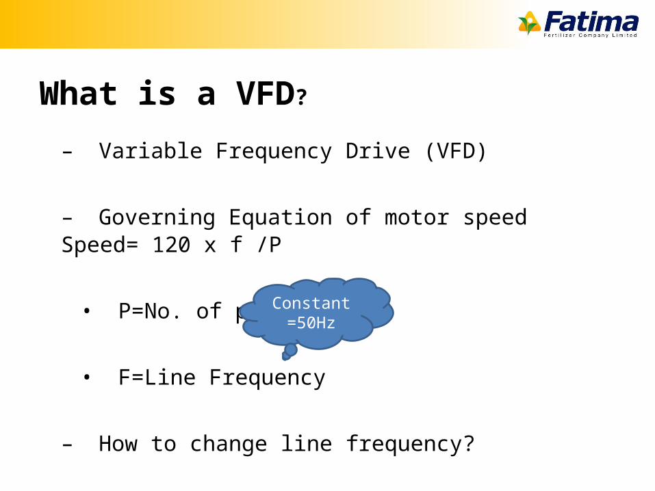
What is a VFD?
– Variable Frequency Drive (VFD)
– Governing Equation of motor speedSpeed= 120 x f /P
• P=No. of poles
• F=Line Frequency
– How to change line frequency?
Constant =50Hz
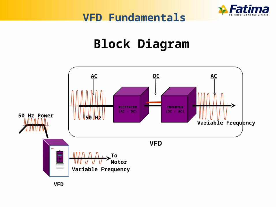
Block Diagram
VFD Fundamentals
50 Hz Power
Electrical Energy
ABB
Variable Frequency
To Motor
VFD
RECTIFIER(AC - DC)
INVERTER(DC - AC)
AC DC AC
VFD
Variable Frequency50 Hz
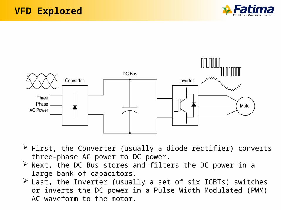
VFD Explored
First, the Converter (usually a diode rectifier) converts three-phase AC power to DC power.
Next, the DC Bus stores and filters the DC power in a large bank of capacitors. Last, the Inverter (usually a set of six IGBTs) switches or inverts the DC power in a
Pulse Width Modulated (PWM) AC waveform to the motor.
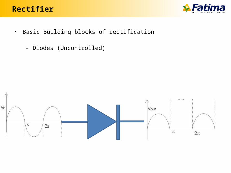
Rectifier
• Basic Building blocks of rectification
– Diodes (Uncontrolled)
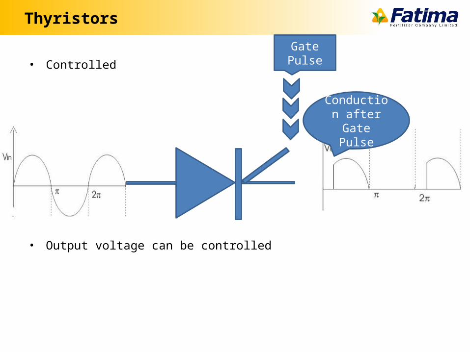
Thyristors
• Controlled
• Output voltage can be controlled
Gate Pulse
Conduction after Gate
Pulse
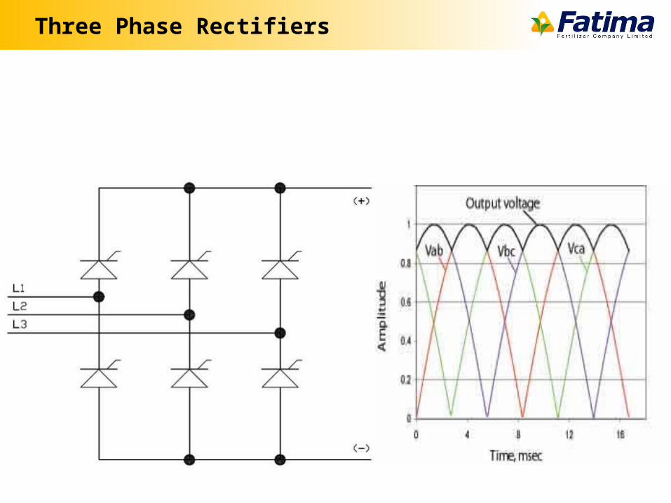
Three Phase Rectifiers
Output Voltage
• Output Voltage (dc) = x – Vm=Peak Value of voltage– A= Firing Angle
• Firing at zero gives maximum output dc voltage
IS it a perfect Direct Current?
• Conversion of AC into DC a perfect process?– Ripples
• How to eliminate the ripples?– Filters
DC bus in VFD
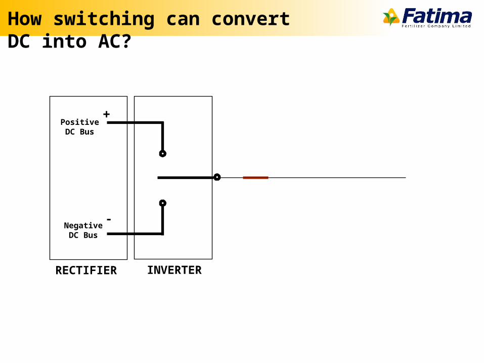
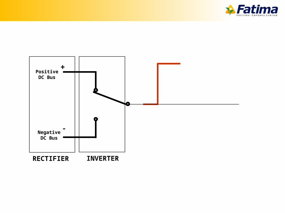
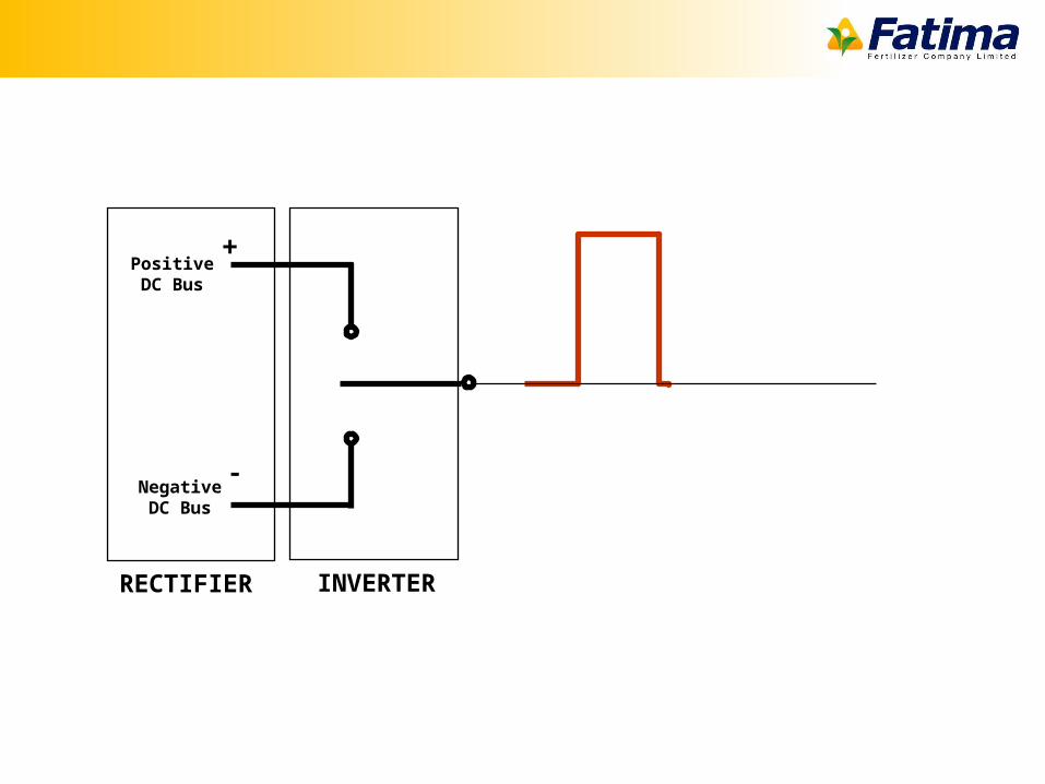
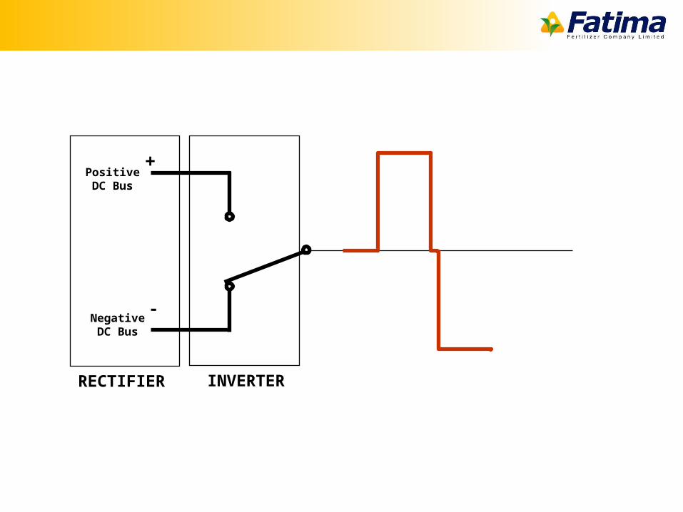
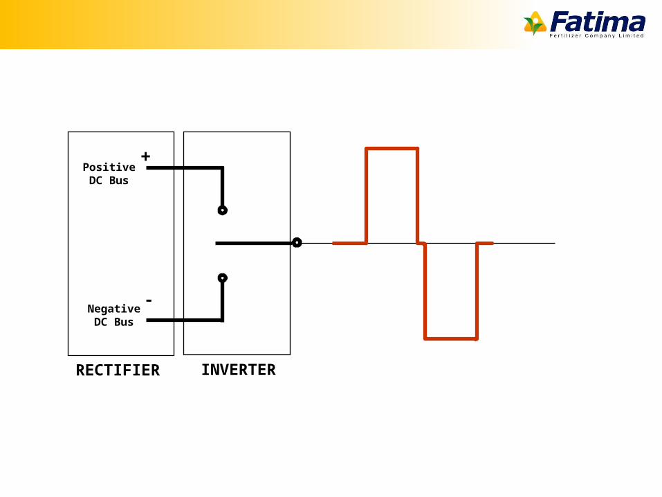
Inverter Action
• Switching DC voltage ON and OFF will make it AC
• Filtered output from DC bus is sent to inverter in VFD
RECTIFIER
PositiveDC Bus
NegativeDC Bus
+
-
INVERTER
How switching can convert DC into AC?
RECTIFIER
PositiveDC Bus
NegativeDC Bus
+
-
INVERTER
RECTIFIER
PositiveDC Bus
NegativeDC Bus
+
-
INVERTER
RECTIFIER
PositiveDC Bus
NegativeDC Bus
+
-
INVERTER
RECTIFIER
PositiveDC Bus
NegativeDC Bus
+
-
INVERTER
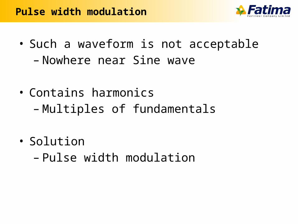
Pulse width modulation
• Such a waveform is not acceptable– Nowhere near Sine wave
• Contains harmonics– Multiples of fundamentals
• Solution– Pulse width modulation
RECTIFIER
PositiveDC Bus
NegativeDC Bus
+
-
INVERTER
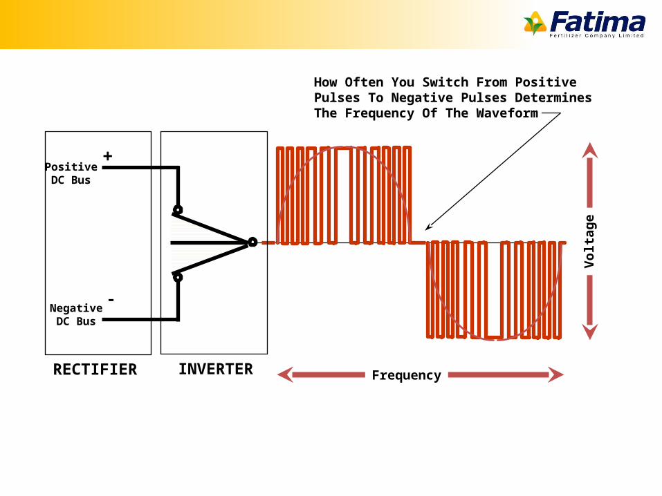
How Often You Switch From PositivePulses To Negative Pulses DeterminesThe Frequency Of The Waveform
Frequency
Vo
lta
ge
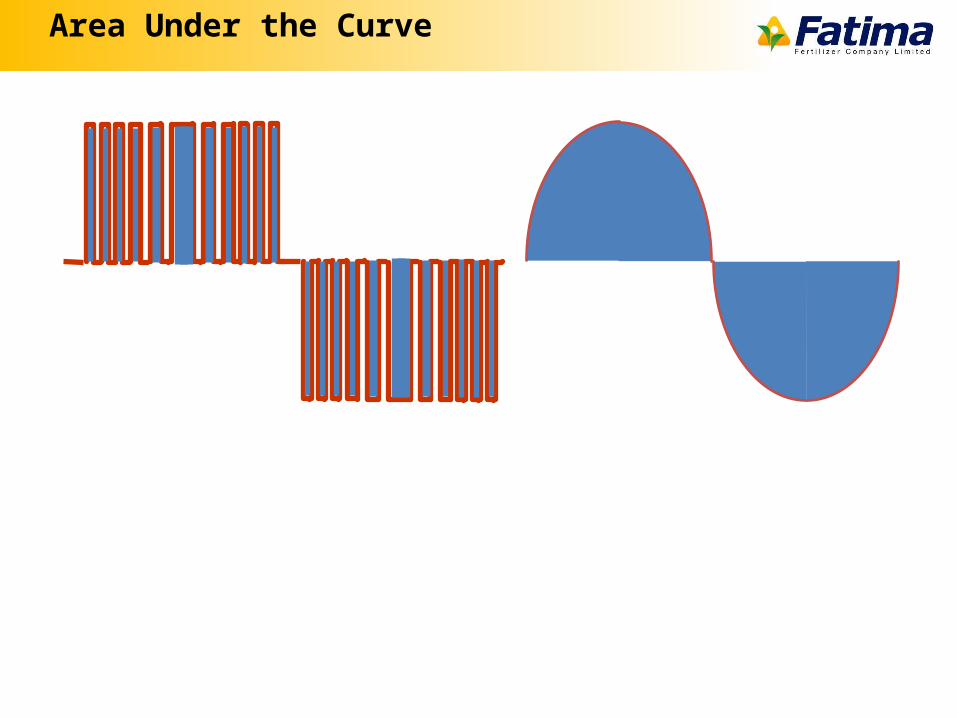
Area Under the Curve
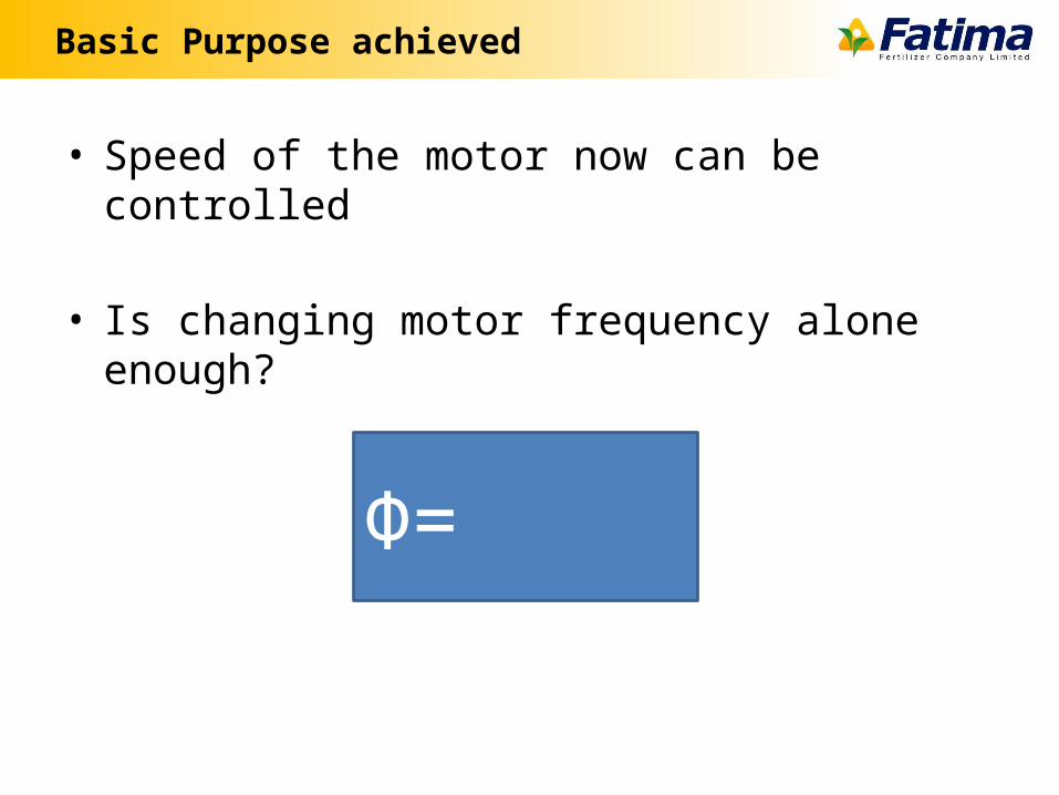
Basic Purpose achieved
• Speed of the motor now can be controlled
• Is changing motor frequency alone enough?
Φ=
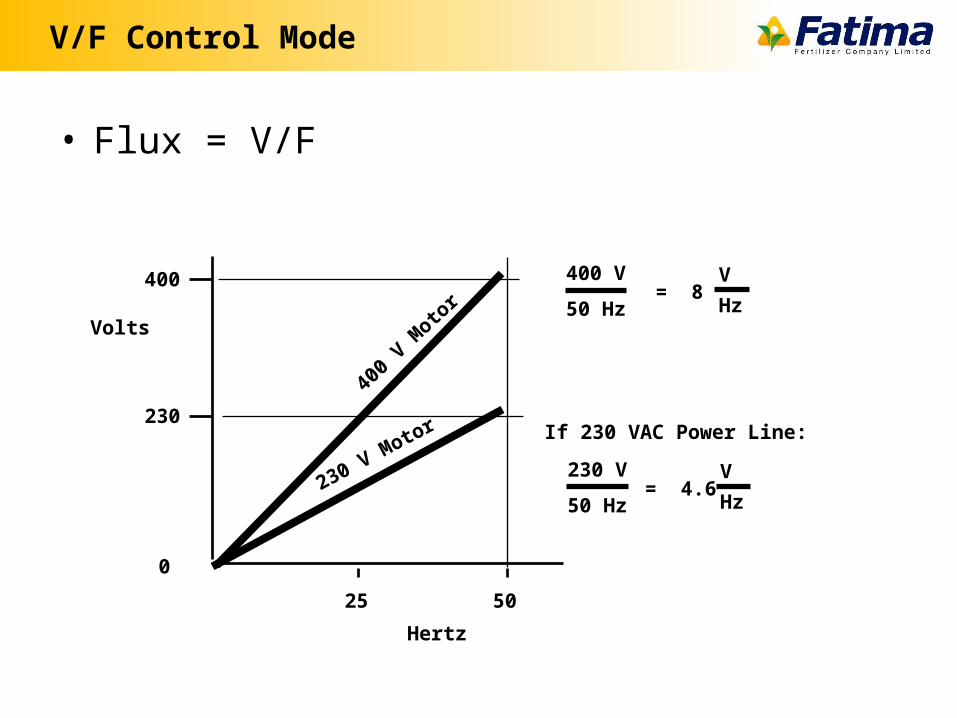
V/F Control Mode
• Flux = V/F
0
230
400
Volts
Hertz
25 50
400 V
50 Hz= 8
V
Hz
230 V
50 Hz= 4.6
V
Hz
If 230 VAC Power Line:
230 V Motor
400
V Moto
r
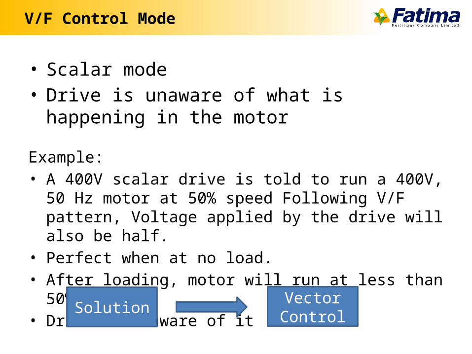
V/F Control Mode
• Scalar mode• Drive is unaware of what is happening in the motor
Example:• A 400V scalar drive is told to run a 400V, 50 Hz motor at 50%
speed Following V/F pattern, Voltage applied by the drive will also be half.
• Perfect when at no load.• After loading, motor will run at less than 50% speed• Drive is unaware of it
SolutionVector Control
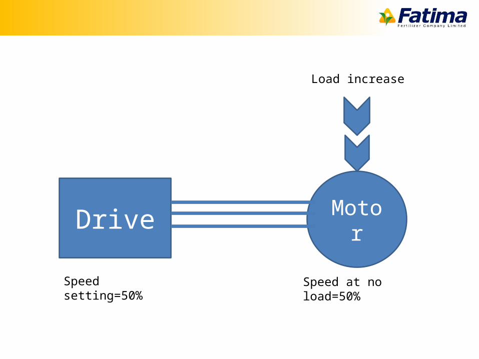
MotorDrive
Speed setting=50% Speed at no load=50%
Load increase
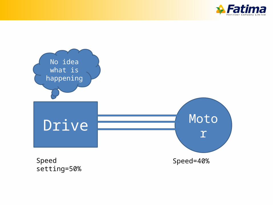
MotorDrive
Speed setting=50% Speed=40%
No idea what is happening
Vector Control Mode
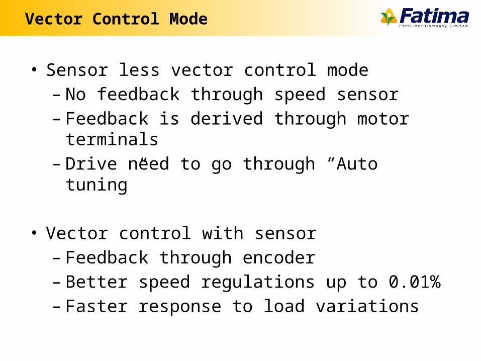
• Sensor less vector control mode– No feedback through speed sensor– Feedback is derived through motor terminals– Drive need to go through “Auto tuning”
• Vector control with sensor– Feedback through encoder– Better speed regulations up to 0.01%– Faster response to load variations
VFD input Parameters
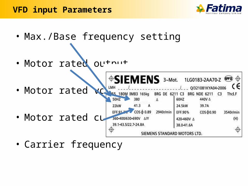
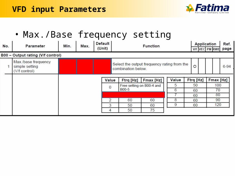
• Max./Base frequency setting
• Motor rated output
• Motor rated voltage
• Motor rated current
• Carrier frequency
VFD input Parameters
• Frequency Reference setting methods
• Stop Command method
• Start frequency
• Stop frequency (DC Braking starts)
• Torque Boost
• Frequency Skip
VFD input Parameters
• Max./Base frequency setting
VFD input Parameters
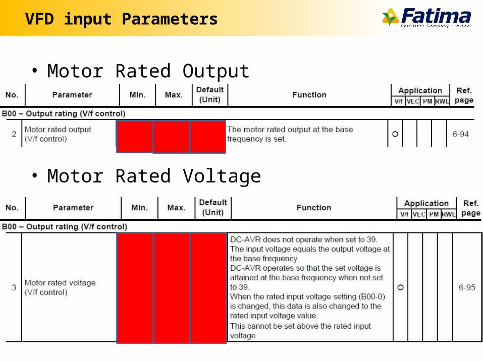
• Motor Rated Output
• Motor Rated Voltage
VFD input Parameters
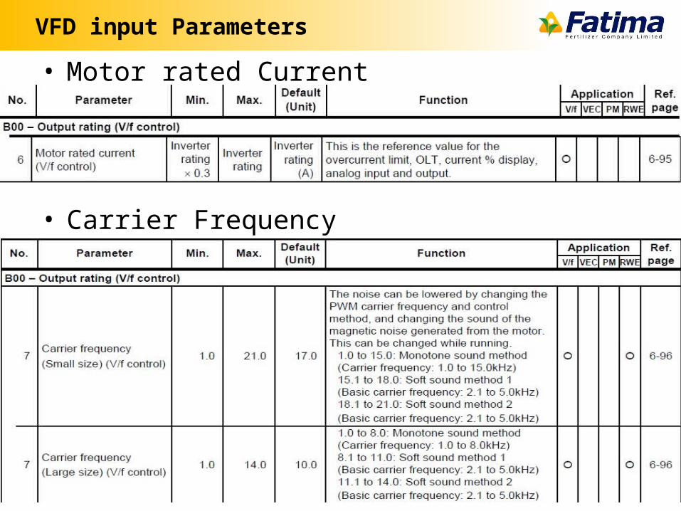
• Motor rated Current
• Carrier Frequency
Frequency Reference Setting Methods
• Potentiometer
• 0-10V input voltage
• 4-20(mA)
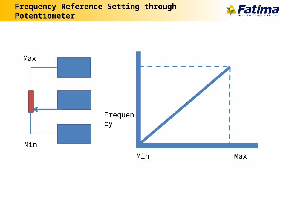
Frequency Reference Setting through Potentiometer
Min
Max
Min Max
Frequency
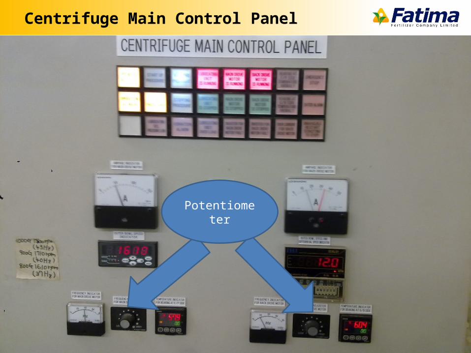
Centrifuge Main Control Panel
Potentiometer
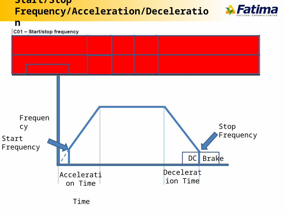
Start/Stop Frequency/Acceleration/Deceleration
Frequency
Start Frequency
Acceleration Time
DC Brake
Stop Frequency
Deceleration Time
Time
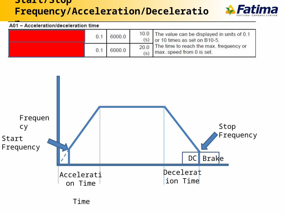
Start/Stop Frequency/Acceleration/Deceleration
Frequency
Start Frequency
Acceleration Time
DC Brake
Stop Frequency
Deceleration Time
Time
Stop Command methods
• Coast to stop
• Ramp to stop
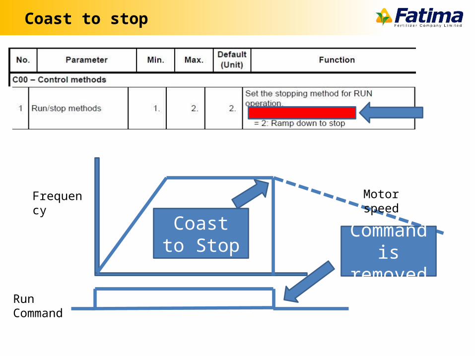
Coast to stop
Coast to Stop
Frequency
Run Command
Motor speed
Command is removed
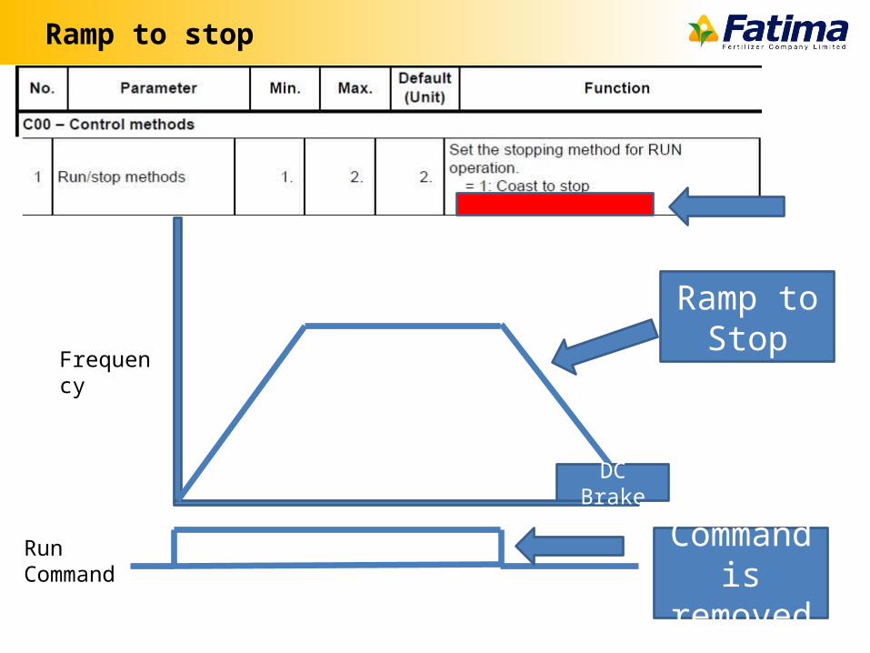
Ramp to stop
Frequency
Run Command Command is removed
DC Brake
Ramp to Stop
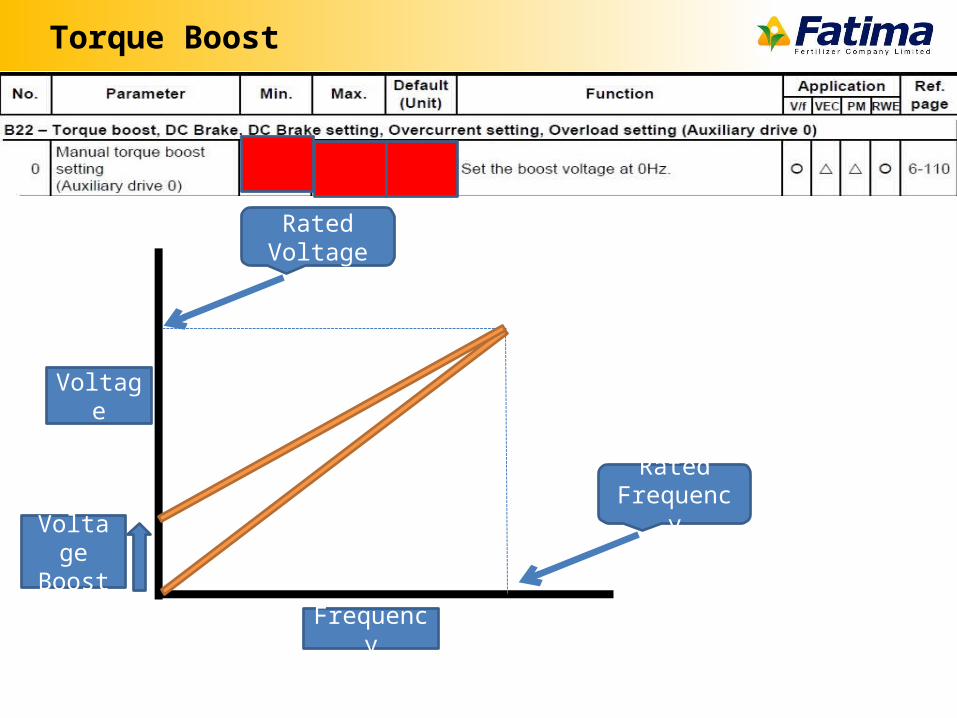
Torque Boost
Voltage
Frequency
Rated Frequency
Rated Voltage
Voltage Boost
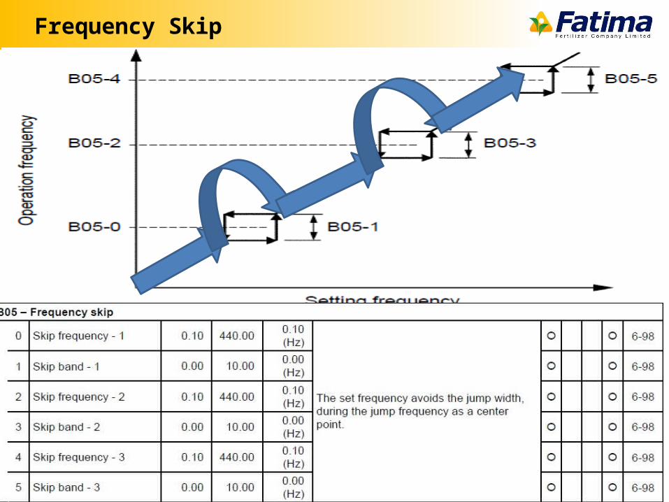
Frequency Skip
Auto Tuning
• Drive familiarizing itself with motor
VFD here I am IM
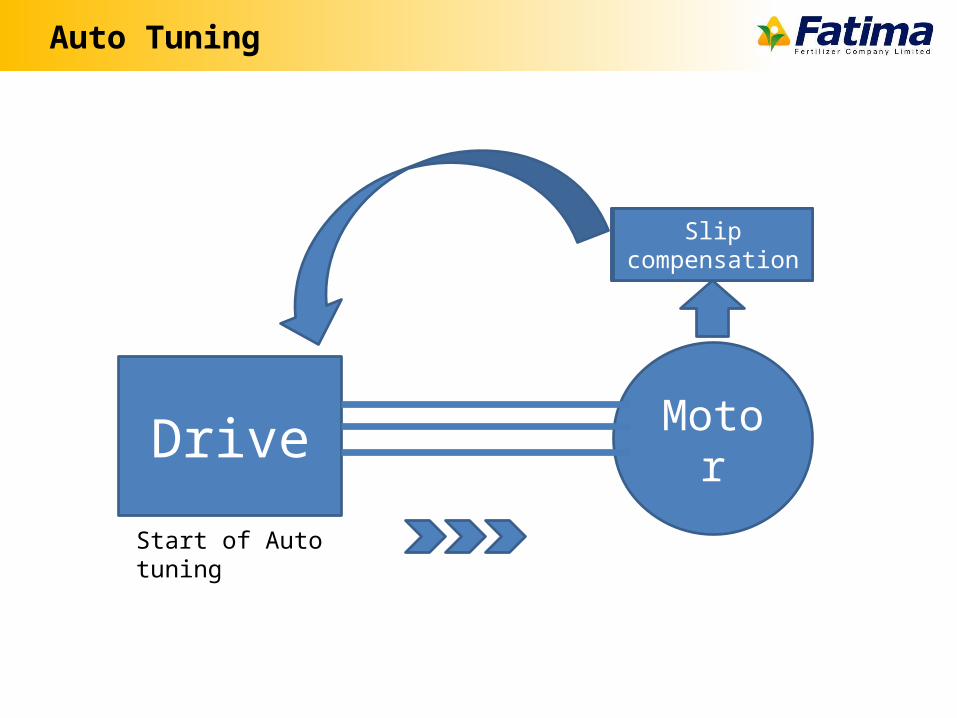
Auto Tuning
MotorDrive
Start of Auto tuning
Primary resistanceLeakage reactanceDC Brake VoltageTorque Boost VoltageSlip compensation
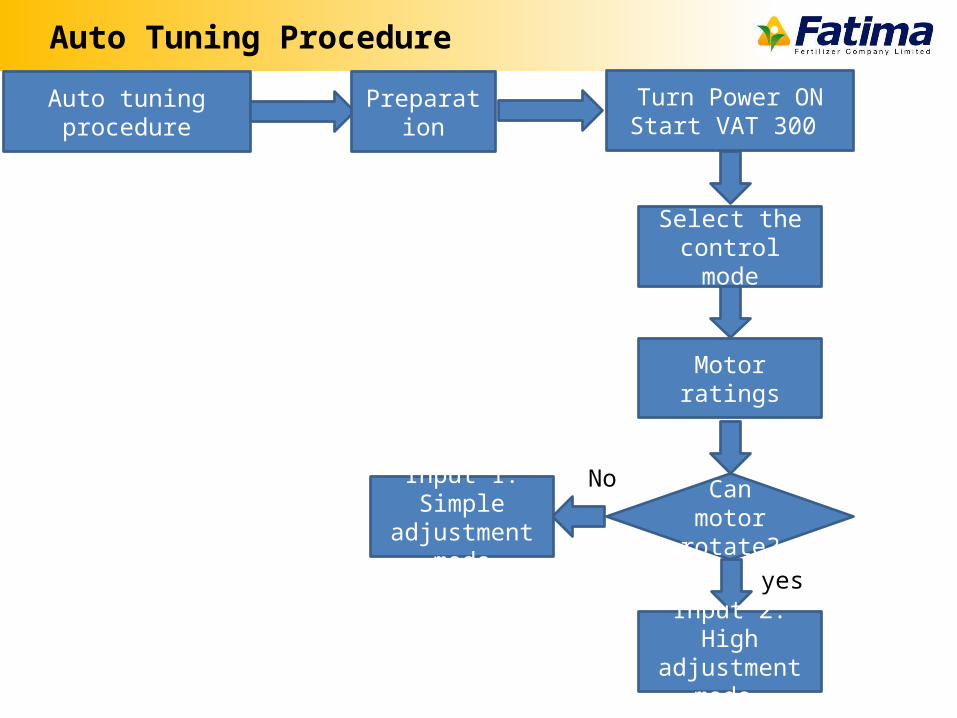
Auto Tuning Procedure
Auto tuning procedure PreparationTurn Power ONStart VAT 300
Select the control mode
Motor ratings
Can motor rotate?
yes
NoInput 1: Simple adjustment
mode
Input 2: High adjustment
mode
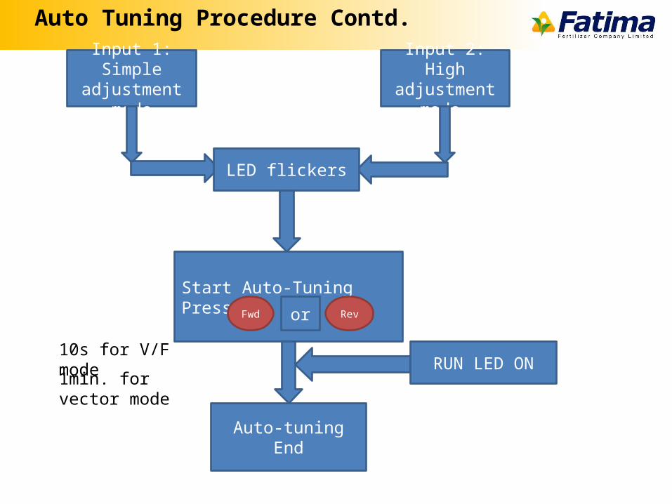
Input 1: Simple adjustment
mode
Input 2: High adjustment
mode
LED flickers
Start Auto-TuningPress Fwd Revor
RUN LED ON
Auto-tuning End
10s for V/F mode
1min. for vector mode
Auto Tuning Procedure Contd.
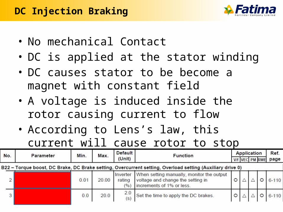
DC Injection Braking
• No mechanical Contact• DC is applied at the stator winding• DC causes stator to be become a magnet with
constant field• A voltage is induced inside the rotor causing current
to flow• According to Lens’s law, this current will cause rotor
to stop
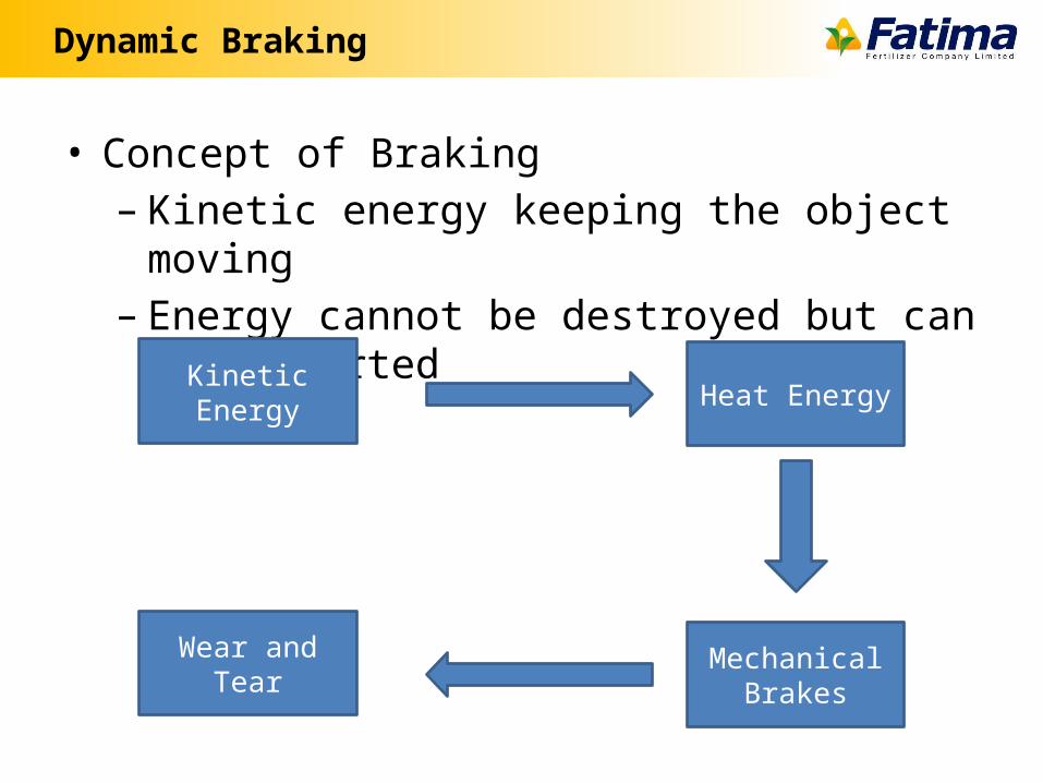
Dynamic Braking
• Concept of Braking– Kinetic energy keeping the object moving– Energy cannot be destroyed but can be converted
Kinetic Energy Heat Energy
Mechanical Brakes
Wear and Tear
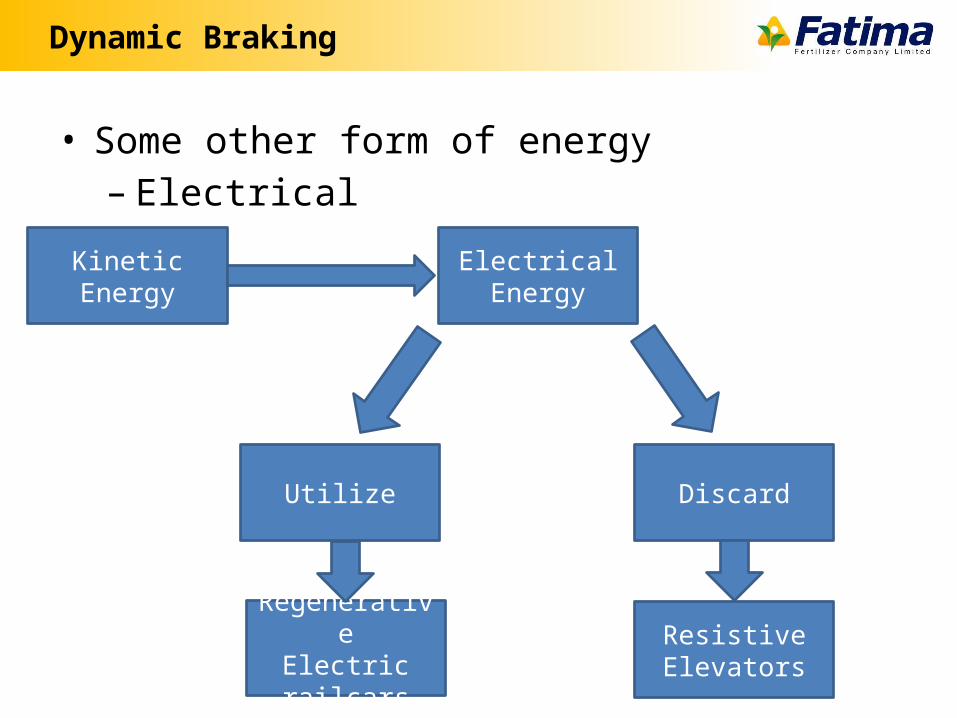
Dynamic Braking
• Some other form of energy– Electrical
Kinetic Energy Electrical Energy
DiscardUtilize
ResistiveElevators
RegenerativeElectric railcars
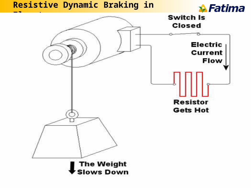
Resistive Dynamic Braking in Elevators
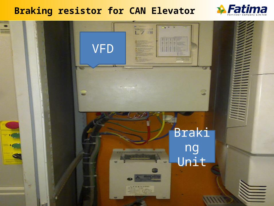
Braking resistor for CAN Elevator
VFD
Braking Unit
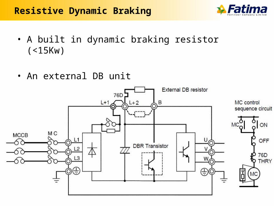
Resistive Dynamic Braking
• A built in dynamic braking resistor (<15Kw)
• An external DB unit
Potential Problems
• Harmonic Distortion
• Bearing Damage
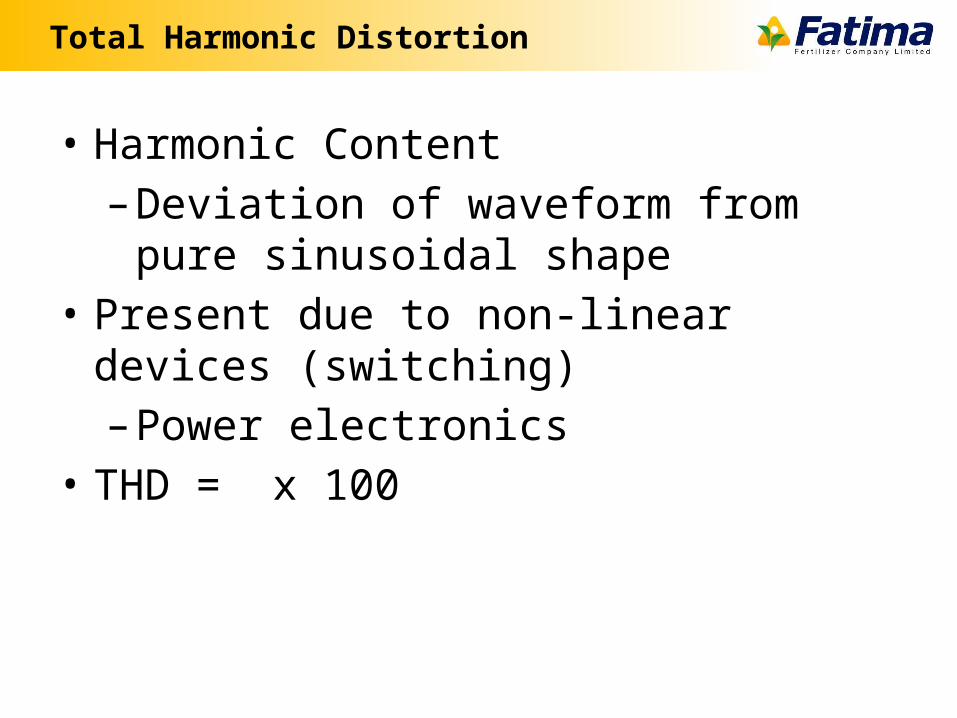
Total Harmonic Distortion
• Harmonic Content– Deviation of waveform from pure sinusoidal
shape• Present due to non-linear devices (switching)
– Power electronics• THD = x 100
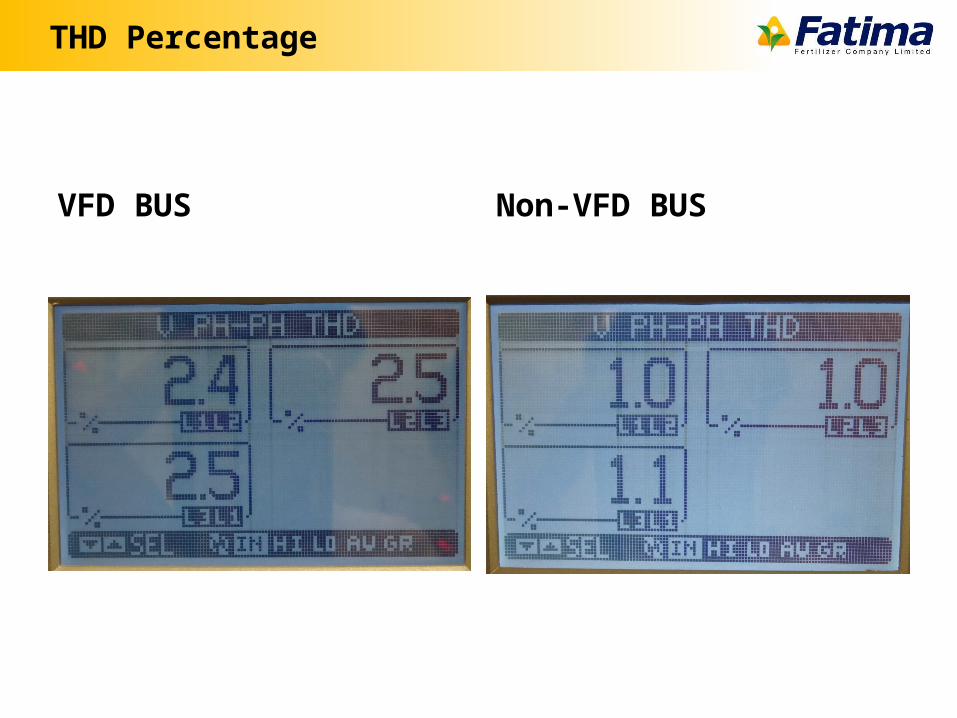
THD Percentage
VFD BUS Non-VFD BUS
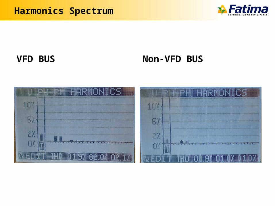
Harmonics Spectrum
VFD BUS Non-VFD BUS
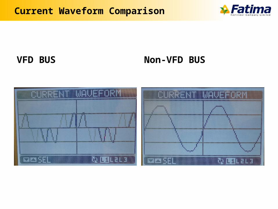
Current Waveform Comparison
VFD BUS Non-VFD BUS
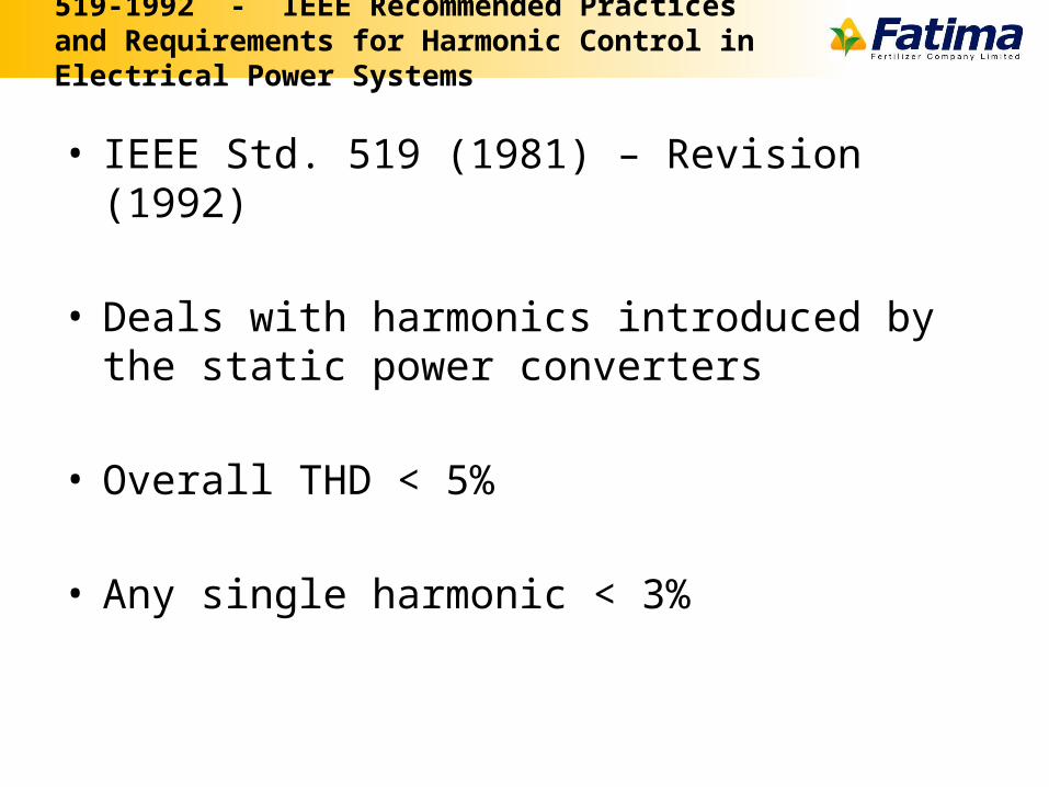
519-1992 - IEEE Recommended Practices and Requirements for Harmonic Control in Electrical Power Systems
• IEEE Std. 519 (1981) – Revision (1992)
• Deals with harmonics introduced by the static power converters
• Overall THD < 5%
• Any single harmonic < 3%
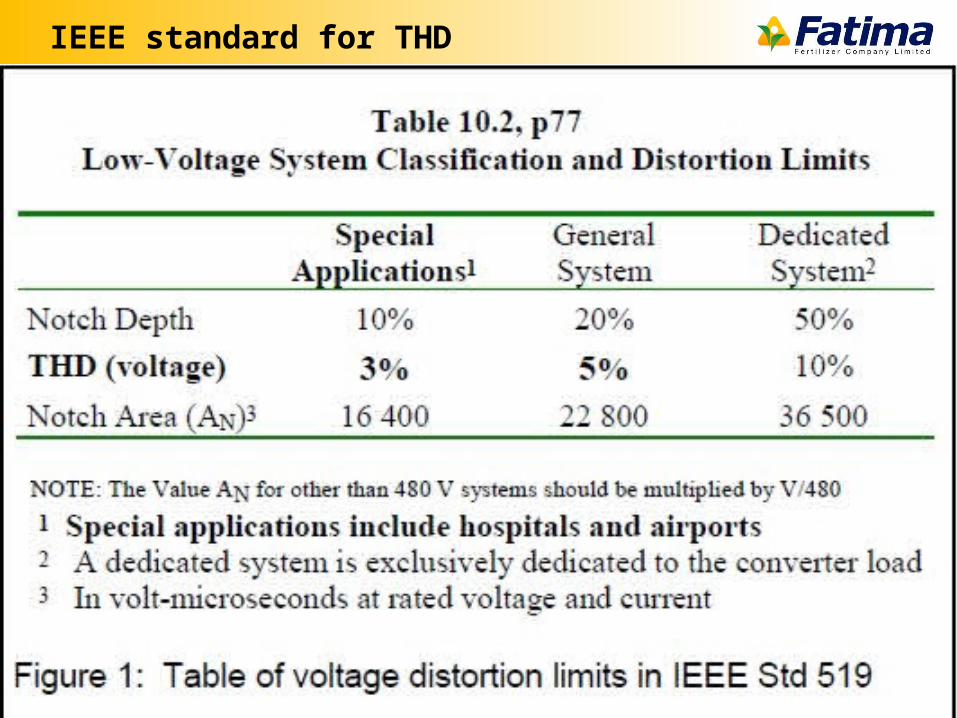
IEEE standard for THD
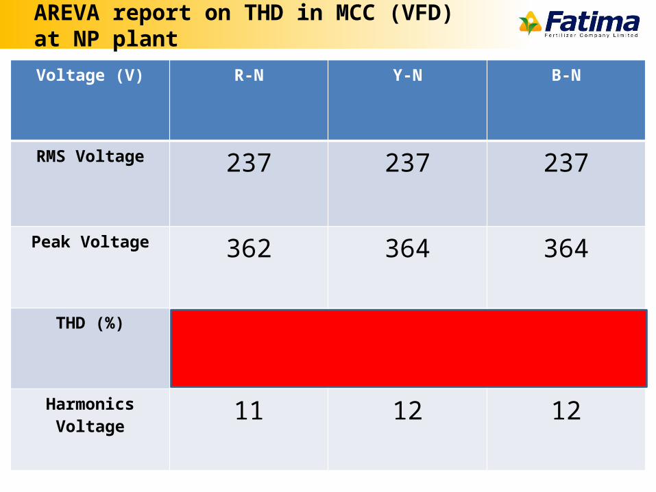
AREVA report on THD in MCC (VFD) at NP plant
Voltage (V) R-N Y-N B-N
RMS Voltage 237 237 237
Peak Voltage 362 364 364
THD (%) 4.7 5 5
Harmonics Voltage 11 12 12
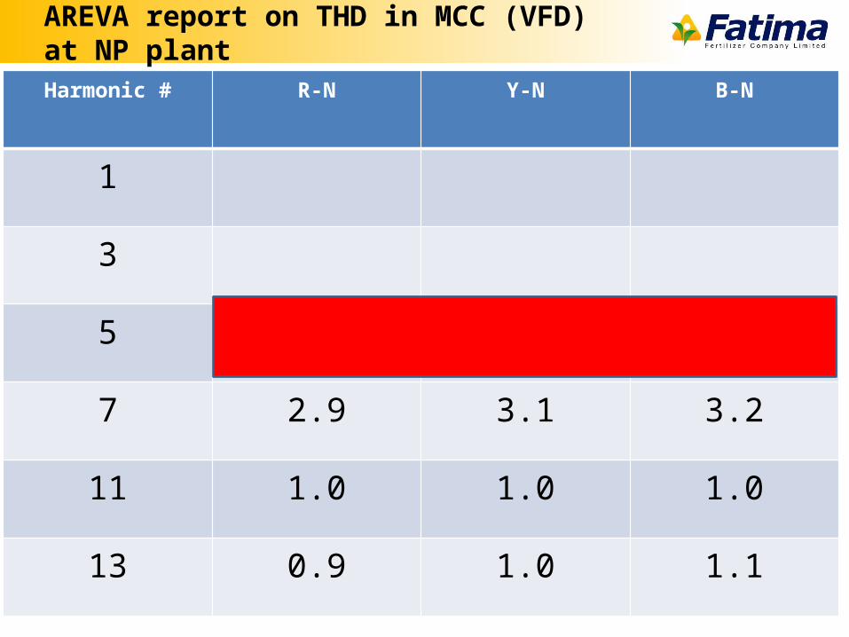
AREVA report on THD in MCC (VFD) at NP plant
Harmonic # R-N Y-N B-N
1
3
5 3.2 3.5 3.4
7 2.9 3.1 3.2
11 1.0 1.0 1.0
13 0.9 1.0 1.1
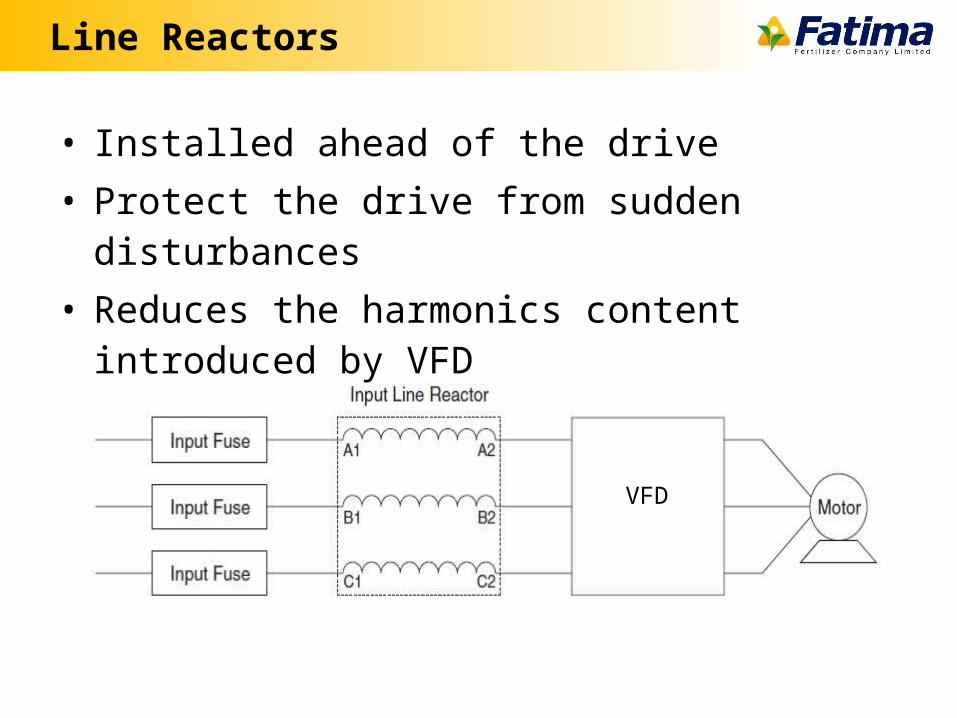
Line Reactors
• Installed ahead of the drive• Protect the drive from sudden disturbances• Reduces the harmonics content introduced by VFD
VFD
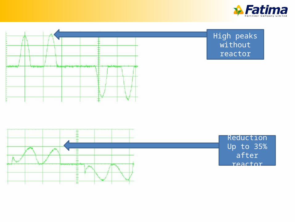
High peaks without reactor
Reduction Up to 35% after
reactor
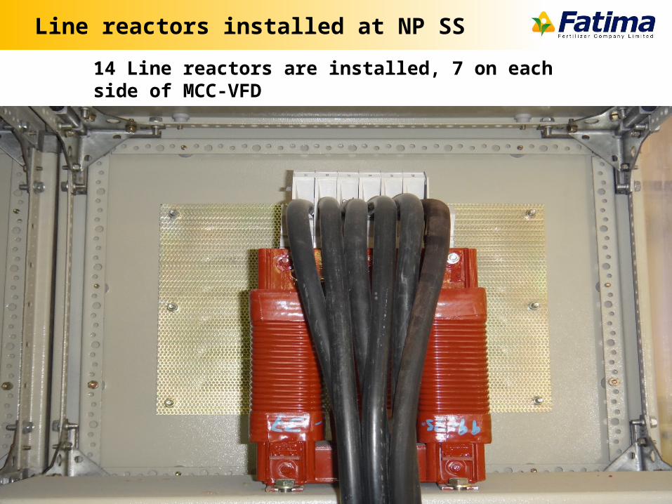
Line reactors installed at NP SS
14 Line reactors are installed, 7 on each side of MCC-VFD
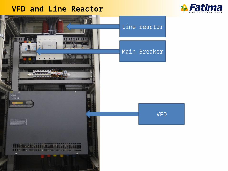
VFD and Line Reactor
Line reactor
VFD
Main Breaker
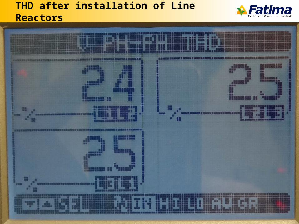
THD after installation of Line Reactors
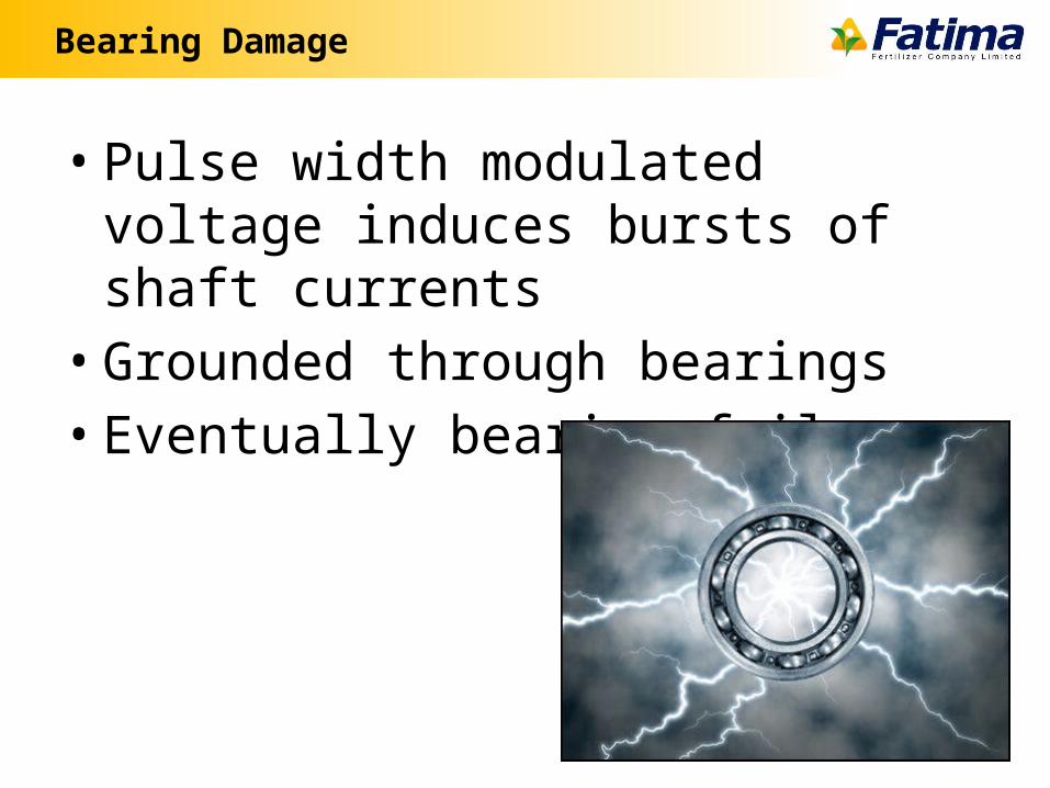
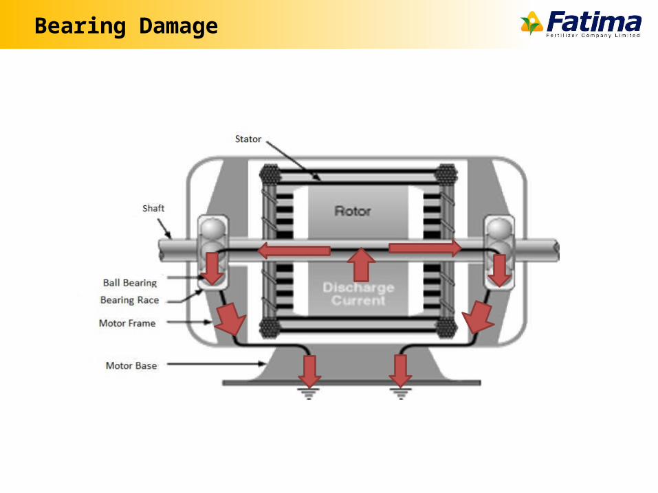
Bearing Damage
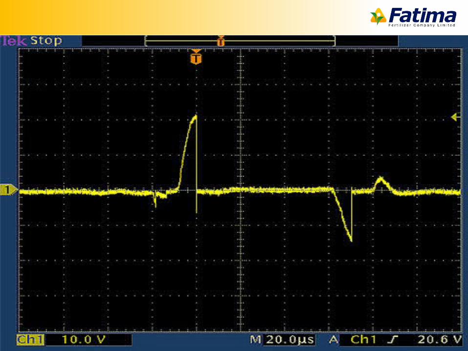
• Pulse width modulated voltage induces bursts of shaft currents
• Grounded through bearings• Eventually bearing failure
Bearing Damage
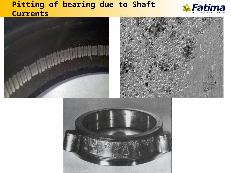
Pitting of bearing due to Shaft Currents
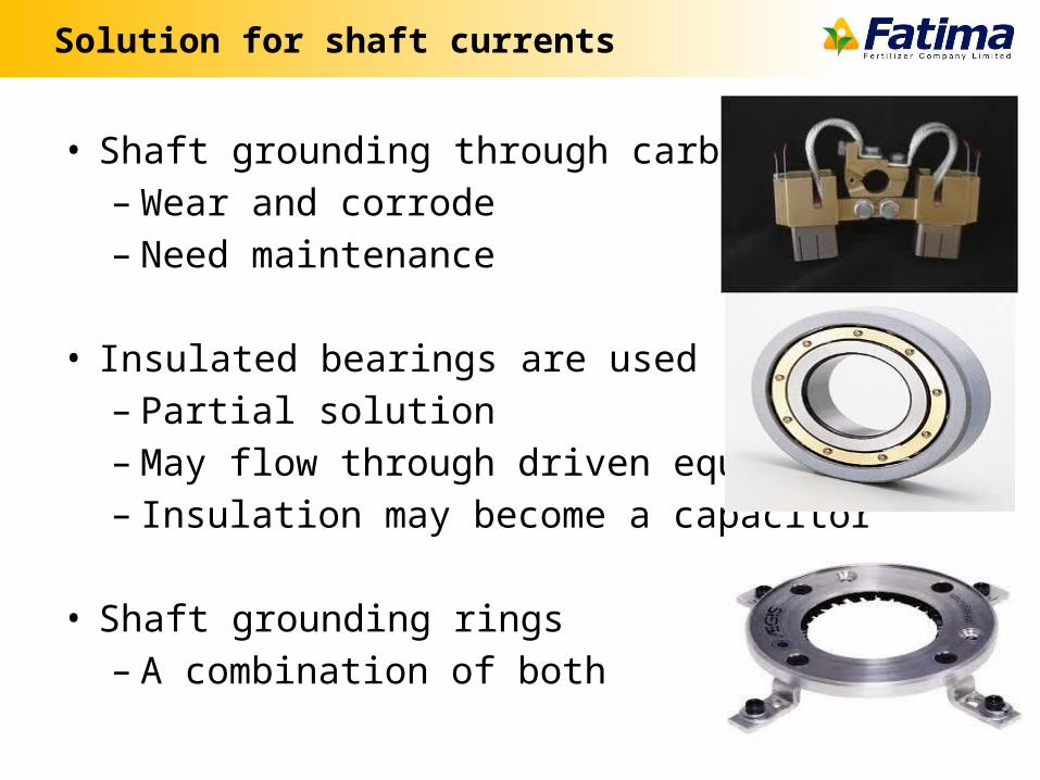
Solution for shaft currents
• Shaft grounding through carbon brushes– Wear and corrode– Need maintenance
• Insulated bearings are used– Partial solution– May flow through driven equipment– Insulation may become a capacitor
• Shaft grounding rings– A combination of both
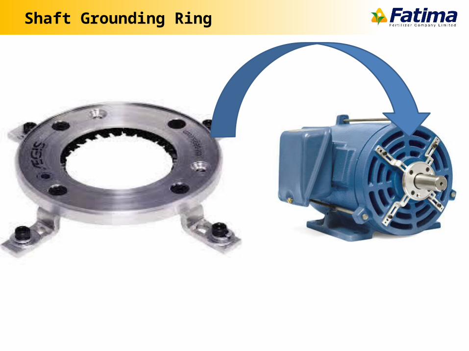
Shaft Grounding Ring

Questions