variable frequency drives (vfd’s) - maeep vfd course.pdf · variable frequency drives presented...
TRANSCRIPT

1
Understanding & Managing
Variable Frequency Drives
Presented by: Greg Stark, P.E.
September 10, 2014
Sponsored by:
Variable Frequency Drives (VFD’s)
• Popular speed control devices
used in industrial, commercial
and residential applications.
– Huge energy savings potential
operating centrifugal fans,
pumps and compressors
• Vary frequency of electrical
supply to an induction motor to
vary the motor speed.
– Vary the speed/flow of the
operation/application.

2
VFD Applications
• Industrial– Fans, Pumps, Compressors
– Conveying Systems
• Commercial– HVAC Compressors
– Pumps and Air Handlers
• Residential– Variable Speed HVAC equipment
– Energy Efficient Washing Machines
How Have We Varied Speed Historically?
• Change Speed
– Belts & pulleys
– Chains & sprockets
– Gear drives
– Multi-speed motors
• Vary Speed
– Variable pitch belts & pulleys
– Eddy current clutch
– Hydrostatic drives
– Wound rotor motor
– DC Drives
– AC Variable Frequency Drives
3
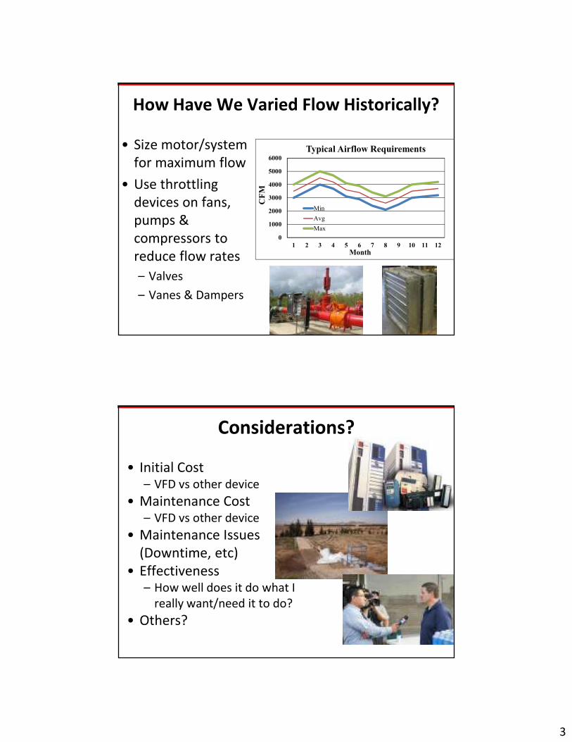
How Have We Varied Flow Historically?
• Size motor/system
for maximum flow
• Use throttling
devices on fans,
pumps &
compressors to
reduce flow rates
– Valves
– Vanes & Dampers
0
1000
2000
3000
4000
5000
6000
1 2 3 4 5 6 7 8 9 10 11 12
CFM
Typical Airflow Requirements
Min
Avg
Max
Month
Considerations?
• Initial Cost– VFD vs other device
• Maintenance Cost– VFD vs other device
• Maintenance Issues
(Downtime, etc)
• Effectiveness– How well does it do what I
really want/need it to do?
• Others?
4
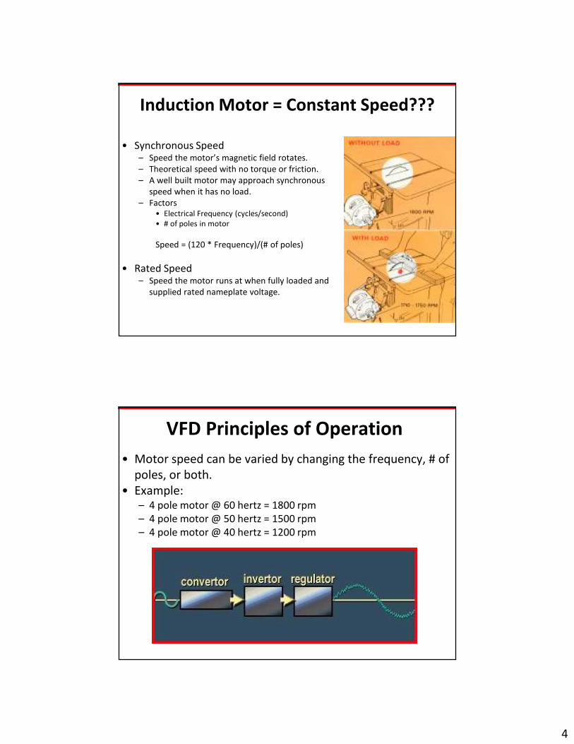
Induction Motor = Constant Speed???
• Synchronous Speed– Speed the motor’s magnetic field rotates.
– Theoretical speed with no torque or friction.
– A well built motor may approach synchronous
speed when it has no load.
– Factors• Electrical Frequency (cycles/second)
• # of poles in motor
Speed = (120 * Frequency)/(# of poles)
• Rated Speed– Speed the motor runs at when fully loaded and
supplied rated nameplate voltage.
VFD Principles of Operation
• Motor speed can be varied by changing the frequency, # of
poles, or both.
• Example:– 4 pole motor @ 60 hertz = 1800 rpm
– 4 pole motor @ 50 hertz = 1500 rpm
– 4 pole motor @ 40 hertz = 1200 rpm

5
Drive Function
• Input:– 60 hertz AC & rated voltage
• Converter– Rectifies to DC & changes
frequency to desired value
• Inverter– Converts DC back to AC
• Regulator– Adjusts voltage level to desired
value as a % of speed/frequency
value.
– Volts/Hertz Ratio• (480/60 = 8)
• AC Output:– Desired frequency and voltage
for speed requirement.
Torque vs Speed
• What happens to torque when
speed is decreased?
– Torque increases
• If torque increases, current
increases and produces
additional heat in the windings.
6
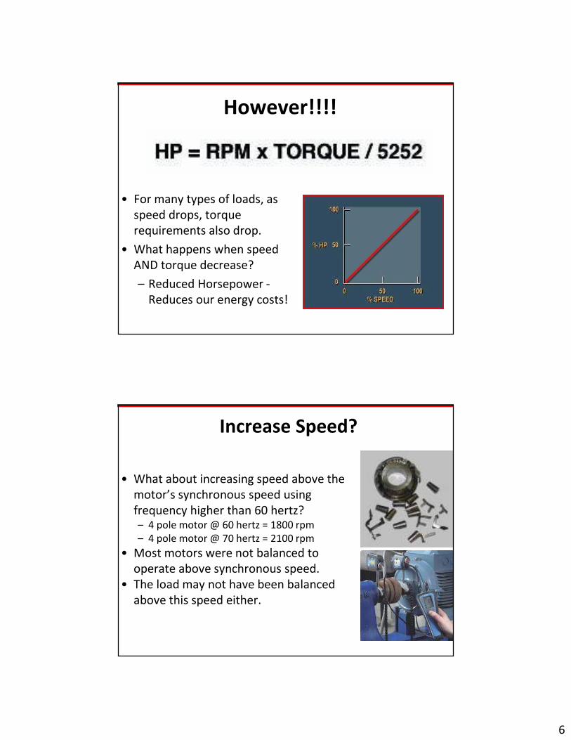
However!!!!
• For many types of loads, as
speed drops, torque
requirements also drop.
• What happens when speed
AND torque decrease?
– Reduced Horsepower -
Reduces our energy costs!
Increase Speed?
• What about increasing speed above the
motor’s synchronous speed using
frequency higher than 60 hertz?– 4 pole motor @ 60 hertz = 1800 rpm
– 4 pole motor @ 70 hertz = 2100 rpm
• Most motors were not balanced to
operate above synchronous speed.
• The load may not have been balanced
above this speed either.
7
Common Applications
• Constant Torque Loads
– conveyor belts, augers,
reciprocating pumps &
compressors, extruders,
gear pumps.
• Variable Torque Loads
– centrifugal fans, pumps,
and compressors
• Constant Horsepower
Loads
– winding machines
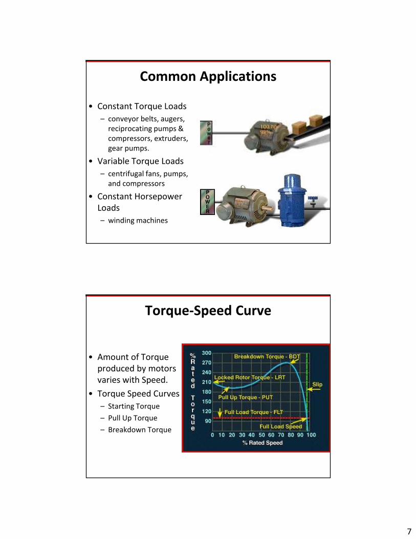
Torque-Speed Curve
• Amount of Torque
produced by motors
varies with Speed.
• Torque Speed Curves
– Starting Torque
– Pull Up Torque
– Breakdown Torque

8
Torque-Speed Issues
• Some single phase
motors have starting
and running windings
• The starting windings
can not be energized
continuously
• If a VFD is used and
speed is reduced too
much the starting
windings burn out.
Constant Torque Loads
• Require the same amount of
torque at low speeds as high
speeds.– For a given weight on the belt, the
torque to turn the belt is always
the same regardless of speed.
• Horsepower increases or
decreases as a direct function of
speed.
• Examples:– Conveyor belts, reciprocating
pumps & compressors

9
Constant Torque Loads
• Horsepower increases or
decreases as a direct function
of speed.– A 50% drop in speed produces a
50% reduction in power required to
turn the load.
• Energy savings using a VFD to
control the speed of a
constant torque load is a
direct function of speed
reduction.
Variable Torque Loads
• Require much lower torque &
horsepower at low speeds than at
high speeds.
• Power required varies as the cube
of the speed.
• Examples:
– Centrifugal fans, pumps &
compressors, mixers and agitators.

10
Variable Torque Loads
• Horsepower increases or
decreases as cubic function of
speed.– A 50% drop in speed produces
almost an 88% reduction in power
required to turn the load.
• Energy savings using a VFD to
control the speed of a
variable torque load can be
very large due to how
centrifugal loads operate.
Constant Horsepower Loads
• Constant horsepower loads
include equipment such as
grinders, winders, and lathes. – Since the power required
remains the same regardless of
torque or speed requirements of
the operation, there are no direct
energy savings from installing
VFD's with constant horsepower
loads.

11
Constant Horsepower Loads
• Traditionally considered DC
Drive applications
• Some movement to use of
newer AC Flux Vector Drives
• The only justification for
installation of an VFD would
be based on improvement in
the process control of the
operation.
Advantage: Energy Savings
• Traditionally used to justify installation.
• Centrifugal Fans, Pumps, Compressors
– As the speed of the device is slowed, the torque and power required to run the operations is significantly reduced.

12
Throttling Flow May Not Save Energy
• Traditional methods of
reducing flow by throttling
(dampers, vanes, valves) don’t
consistently provide energy
savings.
• Depending on where the
system is on the pump curve,
reducing flow has the result of
increasing pressure on the
back side of the pump and
changing the pump efficiency.
Energy Savings With VFDs
• Using a VFD can result in
significant energy savings when
throttling flow for centrifugal fans,
pumps and compressors.
• The reduction in flow and pressure
in the system from controlling
flow with fan/pump speed will
result in a decrease in power
required to turn the device
resulting in energy savings at the
reduced flow rate.
13
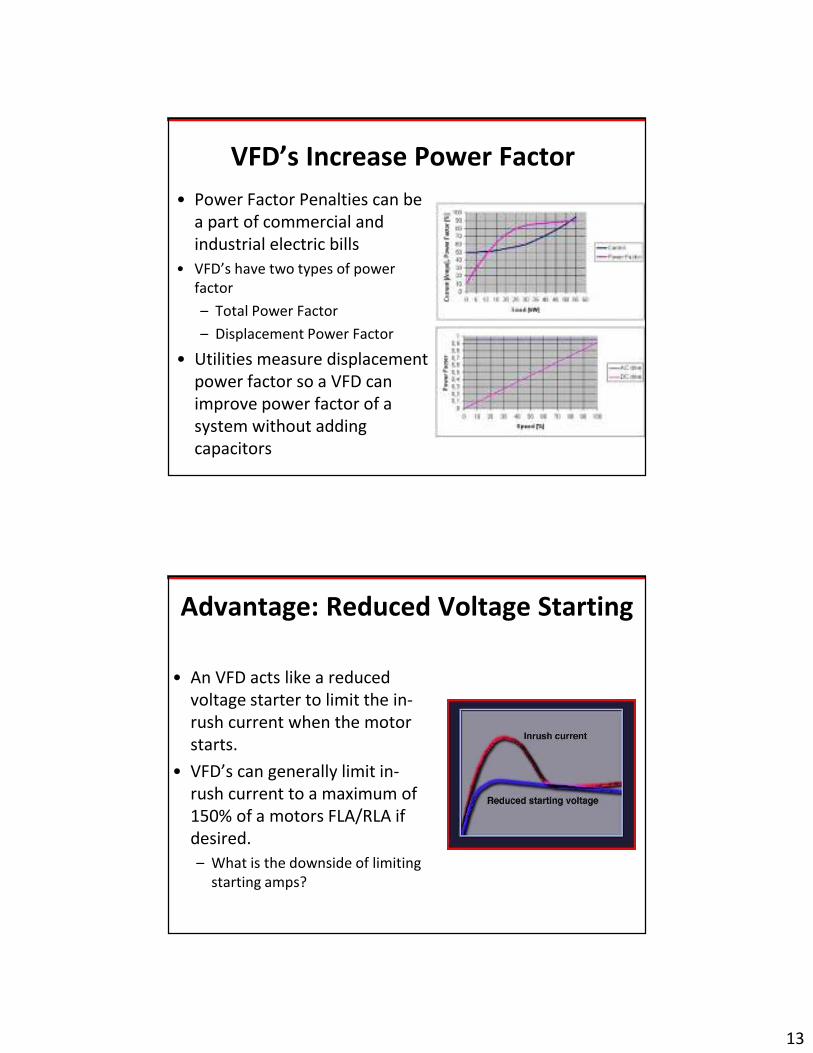
VFD’s Increase Power Factor
• Power Factor Penalties can be
a part of commercial and
industrial electric bills
• VFD’s have two types of power
factor
– Total Power Factor
– Displacement Power Factor
• Utilities measure displacement
power factor so a VFD can
improve power factor of a
system without adding
capacitors
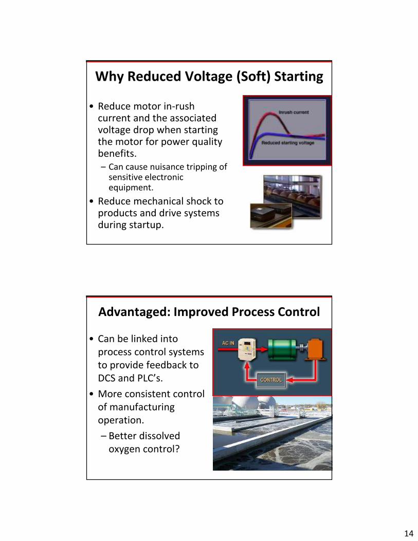
Advantage: Reduced Voltage Starting
• An VFD acts like a reduced
voltage starter to limit the in-
rush current when the motor
starts.
• VFD’s can generally limit in-
rush current to a maximum of
150% of a motors FLA/RLA if
desired.
– What is the downside of limiting
starting amps?
14
Why Reduced Voltage (Soft) Starting
• Reduce motor in-rush current and the associated voltage drop when starting the motor for power quality benefits.
– Can cause nuisance tripping of sensitive electronic equipment.
• Reduce mechanical shock to products and drive systems during startup.
Advantaged: Improved Process Control
• Can be linked into
process control systems
to provide feedback to
DCS and PLC’s.
• More consistent control
of manufacturing
operation.
– Better dissolved
oxygen control?

15
Advantage: Lower System Maintenance
• Eliminate need for maintenance
items in some system.
• Extend operating life of
equipment that is occasionally
overloaded and the system is
not optimized.
• Reduces motor cycling and
associated driveline shock in
some systems.
Can Eliminate Some Maintenance
Requirements
• May eliminate the
need for complex
belt, gearboxes,
valve and damper
systems and the
associated
maintenance
requirements.

16
Maintenance: Reduced
Short Cycling
• Frequently starting and
stopping motors can
significantly reduce their
operating life.
• A VFD can reduce input
flow rate so that pumps
do not have to be
frequently started and
stopped.
VFD Maintenance
• Drives are similar to a power
supply & computer
– Keep it Clean
– Keep it Dry
– Keep connections Tight
• NEMA 1 or NEMA 12 are the
most common enclosures
– NEMA 1 dust and moisture
issues occasionally are an issue
17
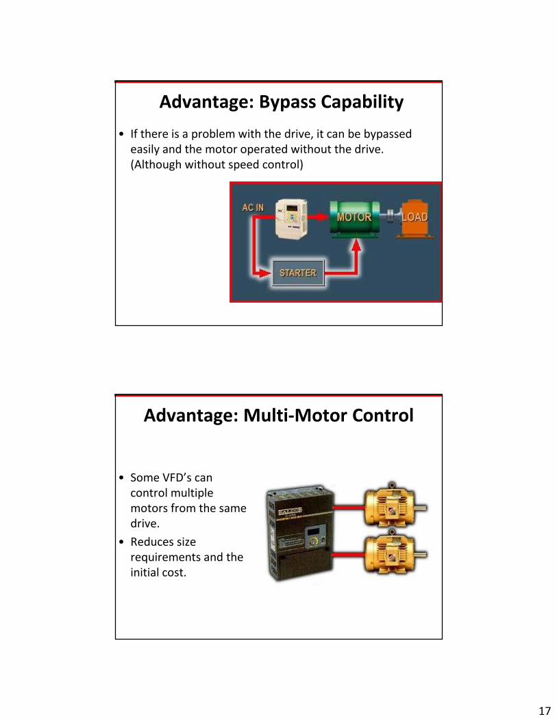
Advantage: Bypass Capability
• If there is a problem with the drive, it can be bypassed
easily and the motor operated without the drive.
(Although without speed control)
Advantage: Multi-Motor Control
• Some VFD’s can
control multiple
motors from the same
drive.
• Reduces size
requirements and the
initial cost.

18
Advantage: Phase Conversion
• VFD’s can be used to operate 3-phase motors from single phase power supplies.
• Motor starting currents of 150% producing full torque starts up to 125 Hp
• Issues:– Cost of VFD vs Phase Converter– Drive is 95% efficient– Need for Reduced Voltage Start?– Eliminates need for “Pump Panel”– Multi-motor control (center pivot)– * Harmonic output is usually
higher when used single phase
Disadvantage: Initial Cost
• Initial cost of an VFD is
greater than the cost of
other types of variable
speed control
equipment.
• Energy savings is
generally low for
applications where
average speed
requirements are near
the motors rated
speed.
19
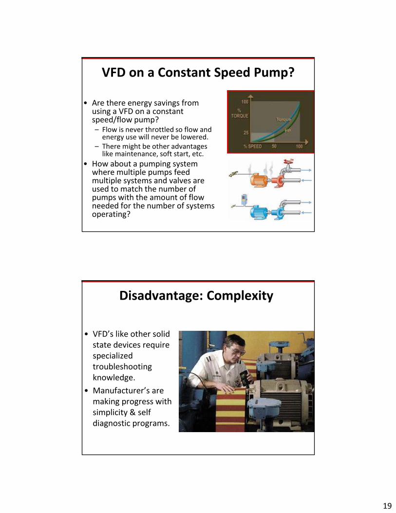
VFD on a Constant Speed Pump?
• Are there energy savings from using a VFD on a constant speed/flow pump?– Flow is never throttled so flow and
energy use will never be lowered.
– There might be other advantages like maintenance, soft start, etc.
• How about a pumping system where multiple pumps feed multiple systems and valves are used to match the number of pumps with the amount of flow needed for the number of systems operating?
Disadvantage: Complexity
• VFD’s like other solid
state devices require
specialized
troubleshooting
knowledge.
• Manufacturer’s are
making progress with
simplicity & self
diagnostic programs.
20
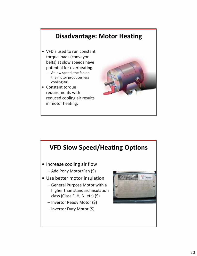
Disadvantage: Motor Heating
• VFD’s used to run constant
torque loads (conveyor
belts) at slow speeds have
potential for overheating.– At low speed, the fan on
the motor produces less
cooling air.
• Constant torque
requirements with
reduced cooling air results
in motor heating.
VFD Slow Speed/Heating Options
• Increase cooling air flow
– Add Pony Motor/Fan ($)
• Use better motor insulation
– General Purpose Motor with a
higher than standard insulation
class (Class F, H, N, etc) ($)
– Invertor Ready Motor ($)
– Invertor Duty Motor ($)

21
Disadvantage: Power Quality
• VFD’s can produce significant input & output waveform distortion including harmonic distortion, noise and line notching.
• Input Side– Can cause multiple problems
impacting sensitive electronic devices, transformers, capacitors, neutral conductors and neighboring services.
• Output Side– Causes multiple issues for
motors and circuit conductors.
Drives As Power Quality Problem Sources
1. Induce harmonic distortion on the incoming supply lines.
1. Interfere with other electronics at the same service or neighboring services
2. Overload neutrals and transformers
3. Strange breaker trips
4. Capacitor failures
2. Produce harmonic distortion on the output circuit to the motor/load.
1. Excessive motor heating
2. Excessive bearing vibration/wear
3. Voltage overshoot on motors & cables.

22
Harmonic Distortion
• Harmonic distortion is “noise” created by the operation of electronic devices with “internal AC to DC power supplies”
• It causes the system to resonate at different frequencies of the 60 hertz fundamental.– 2nd is 2 X 60 = 120– 3rd is 3 X 60 = 180– 4th is 4 X 60 = 240
• Odd harmonics are usually the problematic frequencies.
-250
-200
-150
-100
-50
0
50
100
150
200
250
Voltage
Time
Resultant Waveform
Voltage
Time
Harmonic Distortion
3rd Harmonic(+)
(-)
Harmonics Can Be Quantified
• VFD’s produce specific harmonic
frequencies with high
magnitudes.– This “fingerprint” can help
determine where harmonics are
coming from
• Standard Electronic Harmonics– Odd harmonics stairstep down
– 3rd, 5th, 7th, 11th, 13th, 15th, etc.
• VFD harmonics– Function of drive “pulse number”
– Produce “pairs” of odd harmonics
– 5th& 7th, 11th & 13th, etc.

23
Total Harmonic Distortion (THD)
• Common way of quantifying “how much
harmonic distortion” is present.
– The amount of distortion from each harmonic
frequency in a waveform can be measured as a
percentage of the fundamental frequency.
– The individual harmonic % is squared, summed
and the square root taken to determine the total
harmonic distortion (THD) content.
– Example: 7% voltage THD
• 7% of the total voltage is non 60 hertz frequencies
• This is commonly done for both voltage and
current.
Line Side-Harmonic Distortion Interferes
with Operation of Electronics
• Line side harmonic current from drives can distort the distribution voltage within your facility and at other customer locations.
• Distorted current interacts with the system impedance to distort the voltage somewhere else.
• If the harmonics are large enough, they can impact the operation of electronics equipment and VFD’s at neighboring customer locations.

24
Harmonic Current Distortion =
Data Interference Problems
• AC currents generate electromagnetic fields
• The higher the current frequency, the higher the electromagnetic field frequency
• These fields can interrupt data flow causing; data errors, lost data, and slower data transmission rates
Line Side-Unusual Breaker Tripping
• Customers often report having bad breakers
that trip below rated levels.– If measuring the current trip point without a True
RMS device, the current value may not be measured
accurately.• Non-True RMS meters don’t really measure the RMS voltage,
they calculate it based on assuming a pure sine waveform.
• Non-True RMS ammeters commonly measure low when
attempting to measure a highly distorted current.
• Most true RMS meters usually indicate on their
cover that they are true RMS meters. Others
will say in their specifications that they are a
true RMS sensing meter.
– A quick check with the vendor or manufacturer can
verify any questions.

25
Line Side-Overloaded Transformers
• Current harmonics produce abnormal
heating in transformer windings.
– Heating reduces the life of the transformer
• K-Factor Transformers
– Transformer with a higher grade of
insulation to better withstand the
additional heating from the harmonics.
– Should be used where significant harmonic
distortion is present.
• K-Factor can be calculated from
monitoring the harmonic content of
the system.
– Select a higher K-Factor Transformer than
the calculated K-Factor of your system.
Line Side-Harmonics & Capacitors
• Capacitors near the input side of drives
(in the plant or close to the service)
should be carefully analyzed (tuned) to
avoid problems.
• Harmonic resonance
– Causes heating and reduced life in
capacitors.
– Capacitors tuned to one of the
characteristic frequencies (5th, 7th,
etc) will have dielectric failure or
rupture the capacitor.

26
Load Side-Motor Heating
• Reverse sequence harmonics (5, 11, 17, 23, etc) are opposite polarity currents that produce opposing magnetic fields in the windings
– Try to run induction motors in the opposite direction and create heating
– Enough distortion in these frequencies causes excessive motor heating.
– The more harmonic distortion in these frequencies, the higher the excess heating.
• In addition, what happens to airflow when you run a motor at low speed?– The fan runs slower and airflow is
significantly reduced.
Load Side – Bearing Fluting
• Excess bearing vibration and wear problems with VFD’s can come from:
– Resonant Frequencies
– Common Mode Noise from Triplen Harmonics (3,9,15, etc)
• Results in premature bearing failure.
27
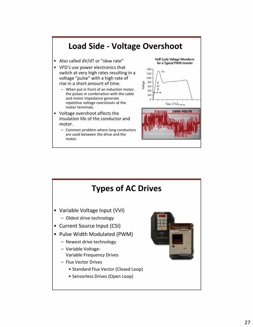
Load Side - Voltage Overshoot
• Also called dV/dT or “slew rate”
• VFD’s use power electronics that switch at very high rates resulting in a voltage “pulse” with a high rate of rise in a short amount of time. – When put in front of an induction motor,
the pulses in combination with the cable and motor impedance generate repetitive voltage overshoots at the motor terminals.
• Voltage overshoot affects the insulation life of the conductor and motor.– Common problem where long conductors
are used between the drive and the motor.
Types of AC Drives
• Variable Voltage Input (VVI)
– Oldest drive technology
• Current Source Input (CSI)
• Pulse Width Modulated (PWM)
– Newest drive technology
– Variable Voltage-
Variable Frequency Drives
– Flux Vector Drives
• Standard Flux Vector (Closed Loop)
• Sensorless Drives (Open Loop)

28
Variable Voltage Input (VVI)
• 1st AC Drive to gain
acceptance.
• Called “Six-Step Drive”
• Advantages– Good speed range
– Multiple motor control
– Simple control
• Disadvantages– Power factor
– Poor ride through
– Significant output harmonics
– Low speed cogging
– Isolation Transformer
Current Source Input (CSI)
• Voltage closer to output
expected by motor.
• Sold as motor/drive
package.
• Advantages– High efficiency
– Regeneration
• Disadvantages– Power factor
– Low speed cogging
– Poor ride through
– Isolation transformer
– Large physical size

29
Pulse Width Modulated (PWM)
• Newest technology & lowest price.
• Best current waveform to the motor.
• Advantages
– High efficiency
– Wide speed range
– High power factor
– No cogging
• Disadvantages
– Complexity of equipment
– Significant audible noise
PWM Drive Control Types
• PWM drives are sometimes
referred to by their control
type– Variable Voltage Variable
Frequency (VVVF) Drive• Constant Volts/Hertz ratio
– Flux Vector• Can vary volts & hertz
separately
• Closed Loop– Original Flux Vector Drives
• Open Loop– Sensorless Vector Drives

30
Variable Voltage Variable Frequency
(VVVF)
• The standard type of control in early
modern PWM drives.
– Varies output in a constant Volts/Hertz
ratio to control speed.
• Works well for loads where the change in
speed doesn’t have to be instantaneous.
– Mostly steady state conditions
– Fans and pumps
• Lower cost than a Flux Vector Drive
Flux Vector Drive (Closed Loop)
• Uses a more sophisticated drive
controller to modify both the magnitude
and flux direction of the output to the
motor.– Faster, more precise speed response and
control
• Can be important for very sensitive
types of applications and certain types
of constant torque loads.– Traditionally done with DC Drives and
specialty motors.
• Lower cost than a DC Drive but higher
cost than a standard VVVF drive.– Requires use of closed loop controls to
monitor and regulate the driven load
precisely.
31
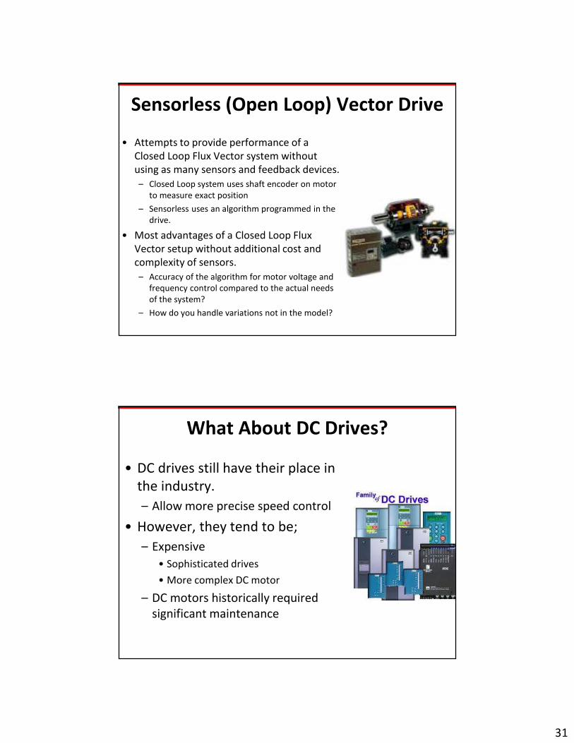
Sensorless (Open Loop) Vector Drive
• Attempts to provide performance of a
Closed Loop Flux Vector system without
using as many sensors and feedback devices.
– Closed Loop system uses shaft encoder on motor
to measure exact position
– Sensorless uses an algorithm programmed in the
drive.
• Most advantages of a Closed Loop Flux
Vector setup without additional cost and
complexity of sensors.
– Accuracy of the algorithm for motor voltage and
frequency control compared to the actual needs
of the system?
– How do you handle variations not in the model?
What About DC Drives?
• DC drives still have their place in
the industry.
– Allow more precise speed control
• However, they tend to be;
– Expensive
• Sophisticated drives
• More complex DC motor
– DC motors historically required
significant maintenance

32
ECM Motors?
• Newer technology
combining a DC Drive and
a DC motor in one
enclosure
• Higher efficiency than
many single phase motors.
• Lower cost than AC VFD
and AC motor
• Lower maintenance costs
than traditional DC motors
AC VFD Drive Pulse Ratings
• Number of current pulses per cycle
depends on rectifier configuration.
• 3 Phase VFD’s use multiples of 6
– (6, 12, 18, 24, etc.)
• The problematic odd harmonic
frequencies can be calculated based on
drive pulse number and compared to the
measured harmonic frequencies.
• Higher the pulse #:
– Lower harmonics
– More complex & costly the drive

33
VFD Harmonics
• VFD’s produce specific harmonic
frequencies with high magnitudes.– This “fingerprint” can help determine
where harmonics are coming from.
• The drive pulse number can be found
from the manufacturer or drive
specification sheet.– The higher the drive pulse number, the
higher the problematic harmonic
frequencies become.
– Because the lower order harmonic
frequencies are generally the most
problematic, a higher drive pulse number
eliminates the most common problem
frequencies.
Pulse Ratings & Harmonics
• Characteristic harmonic current is: h = n x p + 1
– Where h is the harmonic, n is an integer, and p = drive pulses
• 6 Pulse Drive
h = 1 x 6 + 1 = 5 & 7
h = 2 x 6 + 1 = 11 & 13
• 12 Pulse Drive
h = 1 x 12 + 1 = 11 & 13
h = 2 x 12 + 1 = 23 & 25
• As the pulse rating increases, the lower order harmonics
(the most problematic) disappear.

34
Utility Policies are Changing
• Some electric providers are
mandating certain types of drives
and/or mitigating equipment in an
attempt to reduce harmonics.
• Example:– 12 or 18 pulse drive can be used
without line side harmonic
mitigation (filters, chokes or
reactors)
– 6 pulse drive must have line side
harmonic mitigation (filters, chokes
or reactors)
Drive Application & Purchase
Considerations
• Cost/Benefit Ratio?– Historically energy savings were used to
justify.
• Improved Process Control– More consistency and less off spec
product?
• Maintenance– Reduce scheduled
downtime/maintenance requirements?
• Power Quality– Can I use my existing motors and do I
need filters?

35
NEMA Application Guide for AC
Adjustable Speed Drive Systems
• Developed by NEMA in 2001 to assist users in proper
selection & application of drives. (81 pages)
• Price:
– $93 for hardcopy
– Electronic download is FREE
www.nema.org and search for title of document.
NEMA Drive Selection &
Application Factors
• Motors– Suitable for the application such that drive operating conditions will not
substantially reduce the life of the motor.
• Drive Type– Selected and installed to limit power quality disturbances to a minimum
• Electric Supply– Within NEMA tolerances to ensure the equipment will operate correctly
• Mechanical Installation– Within NEMA tolerances to ensure the equipment does not have reduced life
• Controls– Life Safety
– Fuses or Breakers as specified
– Data acquisition or PLC systems
36
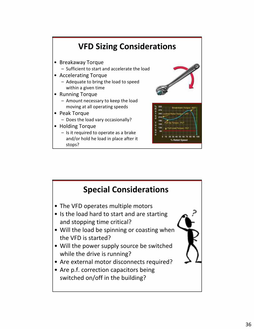
VFD Sizing Considerations
• Breakaway Torque– Sufficient to start and accelerate the load
• Accelerating Torque– Adequate to bring the load to speed
within a given time
• Running Torque– Amount necessary to keep the load
moving at all operating speeds
• Peak Torque– Does the load vary occasionally?
• Holding Torque– Is it required to operate as a brake
and/or hold he load in place after it
stops?
Special Considerations
• The VFD operates multiple motors
• Is the load hard to start and are starting
and stopping time critical?
• Will the load be spinning or coasting when
the VFD is started?
• Will the power supply source be switched
while the drive is running?
• Are external motor disconnects required?
• Are p.f. correction capacitors being
switched on/off in the building?

37
NEMA Motor Concerns
• Issues:
– Motor Heating
– Bearing Failures
– Insulation Degradation from Voltage Overshoot
• Motor Type Selection
– General Purpose Motor• NEMA Type A,B,C, or D
– Inverter Ready
– Invertor Duty Motor
NEMA Drive Type Concerns
• Issues:
– Input & Output Waveform Distortion
– Voltage Overshoot
– Regeneration
– Low Speed Cogging
• Drive Type Selection
– Variable Voltage Input (VVI)
– Current Source Input (CSI)
– Pulse Width Modulated (PWM)
– Pulse #: 6, 12, 18, 24, 30, etc
38
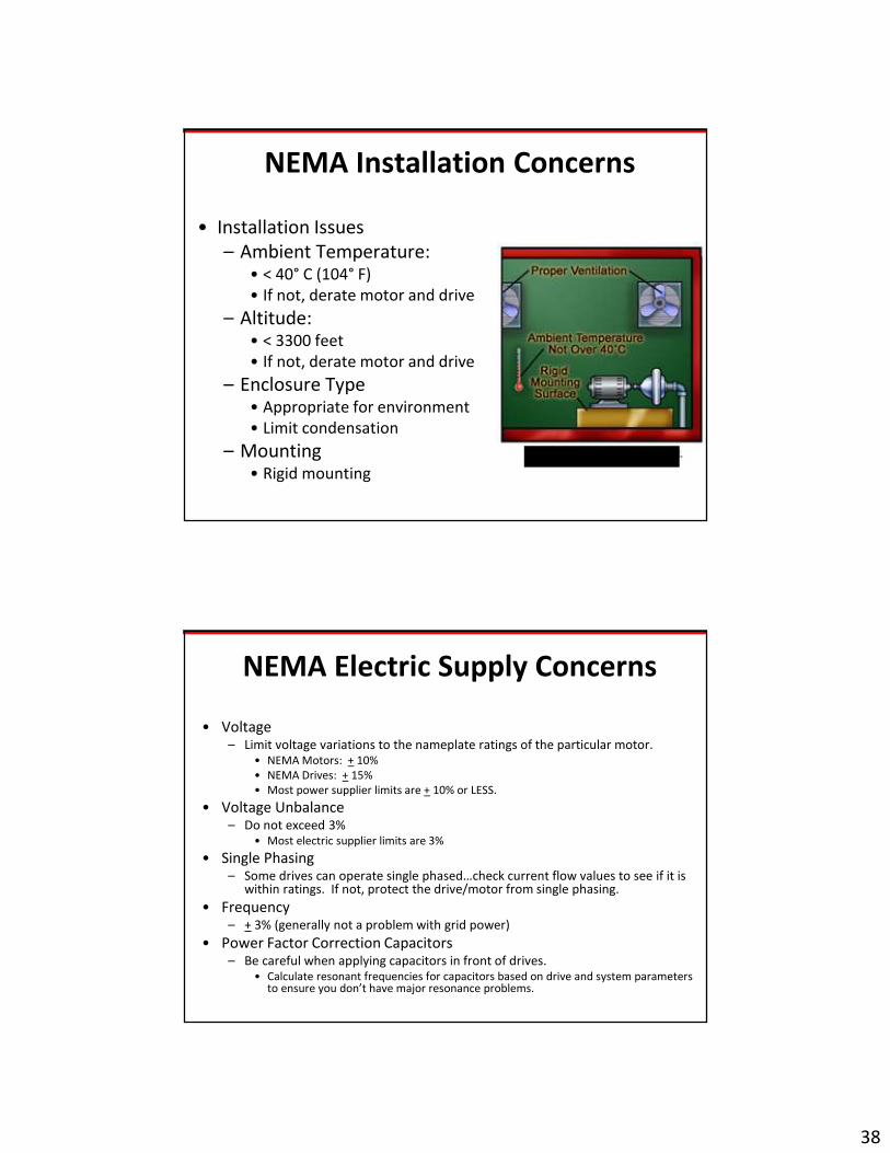
NEMA Installation Concerns
• Installation Issues
– Ambient Temperature:• < 40° C (104° F)
• If not, derate motor and drive
– Altitude: • < 3300 feet
• If not, derate motor and drive
– Enclosure Type• Appropriate for environment
• Limit condensation
– Mounting• Rigid mounting
Altitude not over 3,300 ft.
NEMA Electric Supply Concerns
• Voltage– Limit voltage variations to the nameplate ratings of the particular motor.
• NEMA Motors: + 10%
• NEMA Drives: + 15%
• Most power supplier limits are + 10% or LESS.
• Voltage Unbalance– Do not exceed 3%
• Most electric supplier limits are 3%
• Single Phasing– Some drives can operate single phased…check current flow values to see if it is
within ratings. If not, protect the drive/motor from single phasing.
• Frequency– + 3% (generally not a problem with grid power)
• Power Factor Correction Capacitors– Be careful when applying capacitors in front of drives.
• Calculate resonant frequencies for capacitors based on drive and system parameters to ensure you don’t have major resonance problems.

39
Drives As Power Quality Problem Sources
1. Induce harmonic distortion on the incoming supply lines.
1. Interfere with other electronics at the same service or neighboring services
2. Overload neutrals and transformers
3. Strange breaker trips
4. Capacitor failures
2. Produce harmonic distortion on the output circuit to the motor/load.
1. Excessive motor heating
2. Excessive bearing vibration/wear
3. Voltage overshoot on motors & cables.
Drive Load Side Considerations
• Potential Problems
– Motor heating
• Slower fan speed
• Reverse sequence
harmonics
– Bearing vibration & wear
• Harmonic distortion
– Voltage overshoot
• Harmonic distortion

40
Load Side-Harmonic Trap Filters
• Used to mitigate harmonic distortion
from systems with a high percentage of
non-linear load compared to system
load.– Target multiple harmonic frequencies…not
just a few frequencies.
• Filters can be tuned to the most
problematic frequencies for the system
to eliminate them.
• When the system load changes,
individual filters may be turned on and
off to “follow the load”.
Load Side-Reactors/Chokes
• Reactors and chokes are increasingly being incorporated into many newer and existing VFD installations.– Line and load reactors or chokes
are a very specific type of “filter”.
– If the problematic harmonic frequency(s) is known, a reactor or choke that filters that specific frequency can be installed to remove it. (Tuned or De-tuned)
• Can be much cheaper when only a couple of harmonic frequencies are the problem.

41
Load Side-Motor Heating
• Concern
– Airflow reduction at reduced speed?
– Negative sequence harmonics (5,11,17) have reverse polarity.
• Potential Solutions
– Increase cooling airflow
– Load side filters, chokes or reactors
– Higher pulse number drive
– Better motor insulation• Better General Purpose Motor
• Definite Purpose Motor
Inverter Ready/Duty Motors• General Purpose Motors
– Built in NEMA standard sizes for “general purpose”
– Can work fine in many drive applications.
– Insulation Class B standard unless service factor > 1.0
• Inverter Ready Motors– General purpose motor built with anticipation a drive may be added
in the future. (Class H insulation)
– Will generally have a distance limit the motor can be placed away
from the drive
– May require drive filters, etc outside specific very specific operating
limits
• Inverter Duty Motors– Specially built for most any inverter application
– H insulation class with “inverter spike resistant” (ISR) insulation• Peak voltage limits to 1600 volts
• Corona voltage requirements
– Usually no limits on distance the motor is placed from the drive.
– Will not generally require drive filters, etc unless the application is
far outside normal boundaries.

42
Load Side – Bearing
Vibration & Wear
• Concern
– Excess bearing vibration and wear problems can come from:
• Resonant Frequencies
• Common Mode Noise from Triplen Harmonics (3,9,15, etc)
• Solutions
– Shaft grounding systems
– Insulated bearings
– Load side filters, chokes or reactors.
– Some invertor duty motors
Load Side - Voltage Overshoot
• Also called dV/dT or “slew rate”
• VFD’s use power electronics that switch at very high rates resulting in a voltage “pulse” with a high rate of rise in a short amount of time. – When put in front of an induction motor,
the pulses in combination with the cable and motor impedance generate repetitive voltage overshoots at the motor terminals.
• Voltage overshoot affects the insulation life of the conductor and motor.– Common problem where long conductors
are used between the drive and the motor.

43
Load Side - Voltage Overshoot
• Primary concern is more than 35-50 feet
between drive and motor.
– Down-hole submersible pumps
– Long runs from control panels to pumps
• Primary factors
– Pulse Rise Time, Cable Length, Minimum
Drive Pulse Number, Transition Type (single
vs double), Use of Multiple Motors
• NEMA defines Category I & II
installations.
– Category I – Low probability of problems
– Category II – High probability of problems
Solutions to Voltage Overshoot Problems
• Use inverter duty motor
• Use a lower supply voltage (Wire 230/460 motors at 230).
• Avoid running multiple motors in parallel from one drive.
• Establish a Category I or II installation.
– Category I:• Motor meeting NEMA MG-1 Part 31 voltage limits
should provide normal service life.
– If Category II, do one or both of the following:
• Use a motor with a peak voltage rating that
exceeds the expected voltage overshoot for the
installation.
• Measure the peak voltage at the motor’s
terminals. If the terminal voltage is greater than
the motor’s peak voltage rating, use a dV/dT (slew
rate) filter or reactor between the drive and
motor.

44
Drive Line Side Considerations
• Potential Problems
– Harmonic Distortion
• Neutral heating
• Transformer heating
• Faulty operation of other electronic loads
• Capacitor failure
• Utility/neighboring service complaints
– Nuisance Drive Trips
• Transients
• Interruptions
• Harmonic distortion from elsewhere
• Possible Solutions
– Line side harmonic filters, reactors or chokes.
– Upsized neutrals
– K Factor Transformers
– Check resonant frequency of capacitors vs harmonics produced by drive
– IEEE 519 Guidelines
– Transient Voltage Surge Suppression (TVSS)
– UPS or other ride through protection
Line Side-Transients (Spikes)
• Line side transients can cause
internal damage, nuisance
tripping and drive operation
errors
– Impulsive Transients
• Lightning, Switching Operations, Fault
Clearing/Breaker Operations
– Oscillatory Transients
• Capacitor and transformer switching
• Potential Solutions
– Transient Voltage Surge
Suppression (TVSS)
– Line side chokes or reactors tuned
to the oscillatory transient
Voltage
Time (seconds)
Impulsive Transient(+)
(-)
Voltage
Time
Oscillatory Tranients(+)
(-)

45
Transient Drive Failure Example
• A small machine shop in east Texas is complaining to their power supplier about impulsive transients measured at the Point of Common Coupling (PCC).
• Their drive manufacturer has replaced the same 250 Hp drive three times in the last year and has finally said “no more drives or boards under warranty”.
• Each failure is a problem with the electronics on the circuit boards exhibiting classic signs of overheating according to the drive manufacturer.
• Monitoring by the drive company shows a 3,000 volt transient (480 volt service) that occurs from 0 to thousands of times a day coming in at the electrical service.
Voltage
Time (seconds)
Impulsive Transient(+)
(-)
The Problem/Solution
• A welding shop ¼ mile down the road has an automatic welding process they occasionally run.
• Due to a grounding problem at the welding facility, when the welding machine struck an arc, a high voltage transient was created that propagated along the distribution system, interacted with the system impedance, resonated and grew.
• The Solution:– Welding shop fixed their grounding
problem and transients were reduced.
– Transient Voltage Surge Suppression (TVSS) added at the service of the shop with the drive issues and the problem disappeared.
46
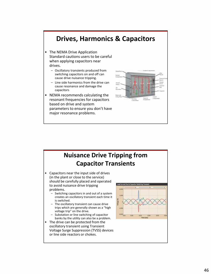
Drives, Harmonics & Capacitors
• The NEMA Drive Application Standard cautions users to be careful when applying capacitors near drives.– Oscillatory transients produced from
switching capacitors on and off can cause drive nuisance tripping.
– Line side harmonics from the drive can cause resonance and damage the capacitors
• NEMA recommends calculating the resonant frequencies for capacitors based on drive and system parameters to ensure you don’t have major resonance problems.
Nuisance Drive Tripping from
Capacitor Transients
• Capacitors near the input side of drives (in the plant or close to the service) should be carefully placed and operated to avoid nuisance drive tripping problems.
– Switching capacitors in and out of a system creates an oscillatory transient each time it is switched.
– The oscillatory transient can cause drive trips which are generally shown as a “high voltage trip” on the drive.
– Substation or line switching of capacitor banks by the utility can also be a problem.
• The drive can be protected from the oscillatory transient using Transient Voltage Surge Suppression (TVSS) devices or line side reactors or chokes.

47
Harmonics Can Cause Capacitor Failure
• Capacitors near the input side of drives (in the plant or close to the service) should be carefully analyzed (tuned) to avoid problems.
• Harmonic resonance– Causes vibration and potential physical
damage if large enough.– Causes heating and reduced life in
capacitors.– Capacitors tuned to one of the
characteristic frequencies (5th, 7th, etc) will have dielectric failure or rupture the capacitor.
• Solution– Calculate the capacitors resonant
frequencies and make sure they aren’t going to be exposed to high amounts of those particular signals
Oscillatory Transient Problem
• A textile knitting mill in south Texas is
experiencing numerous drive trips on
their knitting machines.
• Sometimes all the drives will trip and
sometimes only a handful will trip.
• Almost all the drive trip error messages
indicate “high input voltage”.
• The plant electricians tell management
the utility is providing “dirty” power
because the error message means surges
are happening.
• The utility finds its service voltage within
all applicable standards.

48
The Problem/Solution
• The textile mill installed a staged power factor
correction capacitor system that automatically
switches capacitors on/off to adjust the amount
of reactive power as load changes on-site.
• Each time capacitors in the system are switched
in and out, an oscillatory transient is produced
resulting in a potential “over-voltage condition”
on the drives.
• The Solution:
– The company installed Transient Voltage Surge
Suppression (TVSS) in front of the drive subpanels to
remove the oscillatory transients created by their
automated p.f. correction system.
Harmonic Distortion Problem
• A food processing plant in New Mexico runs 20 drives (350 Hp total) that continually adjust pump speeds in a milk solids separating plant.
• The plant separates the milk solids from water and ships the solids to other food processors without having to pay to ship all the water.
• The electronic controls and computers in the plant freeze/lock up at least every 20 minutes.
• Power factor correction capacitors at the plant have been damaged by something as well.

49
The Problem
• Monitoring equipment shows the current THD to vary between 30 and 37% as the plant operates.
• A half cycle current waveform looked like a capital M.
• The Solution:– The drive manufacturer
recommended installation of an isolation transformer between the subpanel serving the drives and the rest of the electronic and computer equipment in the plant.
– Why not filters……..they were more expensive than the isolation transformer in this instance.
Harmonic Distortion Guidelines?
• NEMA Drive Application Guide:
– It is difficult to suggest guidelines on how to control harmonics for each and every installation.
– That about sums up where we are today with harmonics and drives.
• Wildcards
– # of drives & other electronics (production & sensitivity)
– Impedance of system (wiring, grounding, etc)
• More than 5-8% Voltage THD and you have a potential problem!
– Sometimes it doesn’t take that much.
– I’ve seen much worse where it wasn’t causing any problems.

50
How Much is Too Much?
• IEEE 519-1992; Recommended Practices & Requirements for Harmonic Control in Electrical Power Systems
– Originally published in 1981….later upgraded in 1992.
– Limits harmonics a customer can put back onto the utility line
– Limits harmonic voltage THD a utility can have when supplying a customer.
• The electric utility “benchmark”…..this is what they will use and reference to evaluate whether or not you are putting too much into their system.
• Most utilities refer to this as the level you may not exceed in their contracts or tariffs with customers.
IEEE 519 Harmonic Limits
• Requires a calculation based on the harmonic distortion as a portion
of overall load on site measured at the Point of Common Coupling
(PCC) between customer & utility.– Limits amount of voltage distortion the utility can supply to 5% THD for most
common services.
• Provided the customer’s current THD doesn’t cause the voltage THD
– Limits the amount of harmonic distortion a customer can inject back into the
utility system.
• Current THD < varies with service specifications.
• What is the utilities policy if customers exceed the current THD
contribution from 519?– Politely ask them to fix the problem?
– Warn with a grace period of X days?
– Shut them off right now?

51
IEEE 519
• Current Total Demand Distortion (TDD) is measured at the Point of Common Coupling (PCC)
• Isc/IL is the ratio of maximum short circuit current to demand load current at the PCC.
• Current Distortion Limits for General Distribution Systems
(120V through 69,000V)
Maximum Harmonic Current Distortion in Percent of IL
ISC/IL
Individual Harmonic Order (Odd Harmonics)
< 11 11< h < 17 17 < h < 23 23 < h < 35 35 < h TDD
< 20 4.0 2.0 0.6 0.5 0.5 5.0
20 < 50 7.0 3.5 1.0 0.5 0.5 8.0
50 < 100 10.0 4.5 1.5 0.7 0.7 12.0
100 < 1000 12.0 5.5 2.0 1.0 1.0 15.0
> 1000 15.0 7.0 2.5 1.4 1.4 20.0
•Even harmonics are limited to 25% of the odd harmonic limits.
Enforcement of IEEE 519
• Utilities generally don’t measure & quantify harmonic distortion (THD) unless there is a problem or complaint from a neighboring customer.
• If IEEE 519 limits are being exceeded, the expect the utility to require compliance or face disconnection of your electric system from the grid until compliance can be gained.
• Issues
– Who is being affected?
– Is the solution complex or simple
– Has it been an on-going issue

52
1990’s Harmonic Enforcement Example
• A utility in the OK Panhandle is getting multiple complaints from customers in rural areas near oil company installations of submersible pumps operated by VFD’s
– Electronic equipment exhibits multiple operation problems and resets/reboots frequently.
– Equipment manufacturer says the equipment is working fine when brought in and checked at the shop.
– Checks by the utility show large amounts (8-12%) of voltage THD exceeding IEEE 519 levels on the utility system.
– Customers are also complaining about frequent static on the rural phone system to the extent the phone is un-usable.
• The utility manager writes a letter to the oil companies (5 largest revenue customers) and politely asks them to add filters to their installations to eliminate the harmonics on the system.
– The oil companies supply diesel generators and diesel to the neighboring customers.
– The FCC eventually steps in and tells the utility manager “shut them off to clean up the phone system”.
– A judge sides with the FCC when the utility manager hesitates.
– The oil companies install the necessary filters on their drives.
2010 Enforcement Example
• Harmonics produced by VFD’s in a chemical plant in NM are causing occasional shutdowns of automatic oilers on a natural gas compression station down the road.
• The utility measures THD in excess of IEEE 519 standards and immediately tells plant management they cannot operate their VFD’s until they can comply.
• The chemical plant loses several million dollars in revenue during the shutdown waiting for filters to be installed on the drives so they can commence operation.
53
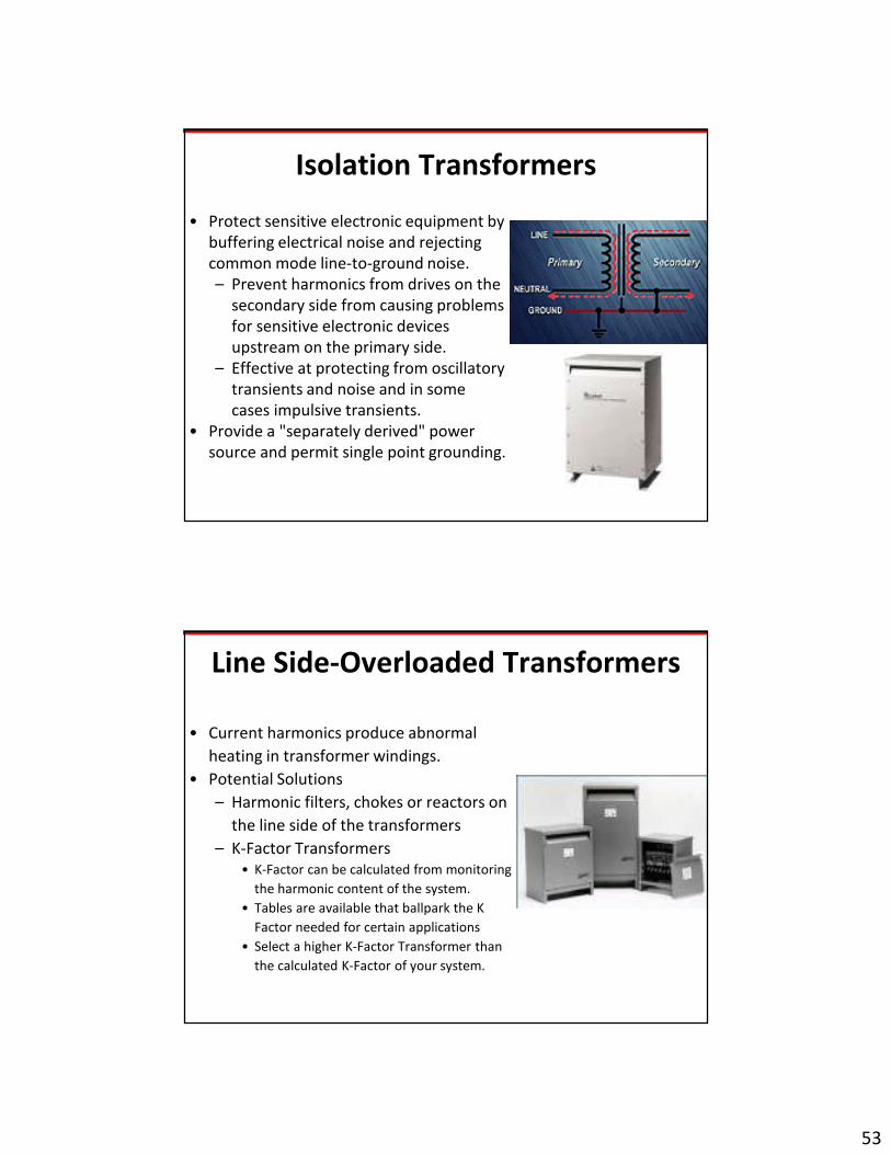
Isolation Transformers
• Protect sensitive electronic equipment by
buffering electrical noise and rejecting
common mode line-to-ground noise.
– Prevent harmonics from drives on the
secondary side from causing problems
for sensitive electronic devices
upstream on the primary side.
– Effective at protecting from oscillatory
transients and noise and in some
cases impulsive transients.
• Provide a "separately derived" power
source and permit single point grounding.
Line Side-Overloaded Transformers
• Current harmonics produce abnormal
heating in transformer windings.
• Potential Solutions
– Harmonic filters, chokes or reactors on
the line side of the transformers
– K-Factor Transformers
• K-Factor can be calculated from monitoring
the harmonic content of the system.
• Tables are available that ballpark the K
Factor needed for certain applications
• Select a higher K-Factor Transformer than
the calculated K-Factor of your system.
54
VFD Energy Efficiency Savings
• Traditionally the energy savings
of using a VFD on applications
where a throttling device
(valve, vane, damper) was used
to choke flow for long periods
was how we justified the
cost/price of a drive.
• If the cost/benefit ratio was
acceptable, the VFD was
installed.
VFD Energy Savings Evaluations
• Motor/Pump Input & Output– Horsepower– Flow Rate– Pressure – Efficiency– etc.
• Duty Cycle– Operating points and times– Example: 100% for 1 hr, 80% for
10 hours and 60% for 8 hours.
• Energy Costs– Energy rate/charge– Demand rate/charge
55
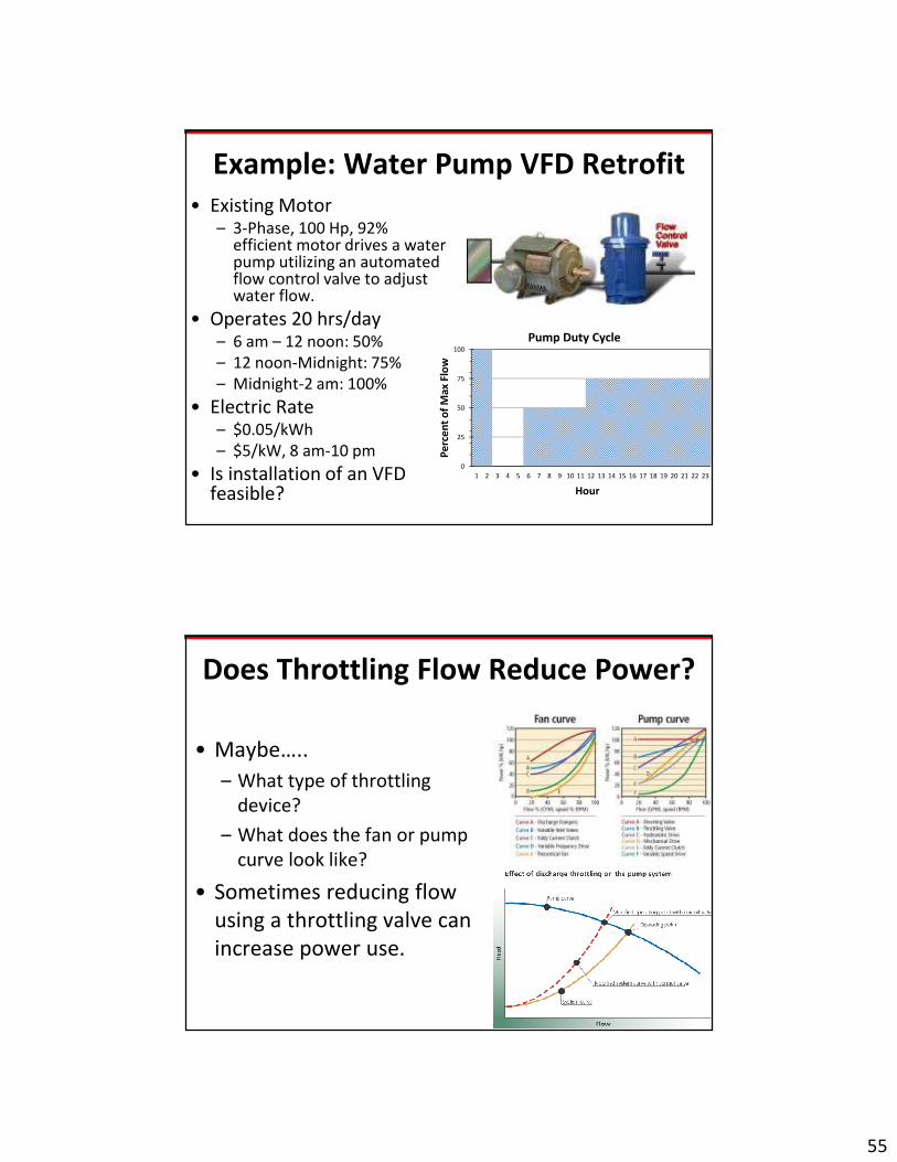
Example: Water Pump VFD Retrofit
• Existing Motor– 3-Phase, 100 Hp, 92%
efficient motor drives a water pump utilizing an automated flow control valve to adjust water flow.
• Operates 20 hrs/day– 6 am – 12 noon: 50%
– 12 noon-Midnight: 75%
– Midnight-2 am: 100%
• Electric Rate– $0.05/kWh
– $5/kW, 8 am-10 pm
• Is installation of an VFD feasible?
0
25
50
75
100
1 2 3 4 5 6 7 8 9 10 11 12 13 14 15 16 17 18 19 20 21 22 23
Pe
rce
nt
of
Ma
x F
low
Pump Duty Cycle
Hour
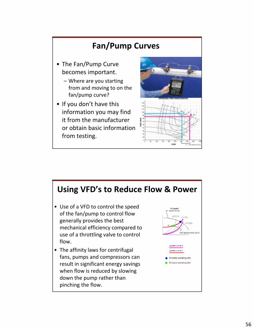
Does Throttling Flow Reduce Power?
• Maybe…..
– What type of throttling
device?
– What does the fan or pump
curve look like?
• Sometimes reducing flow
using a throttling valve can
increase power use.
56
Fan/Pump Curves
• The Fan/Pump Curve
becomes important.
– Where are you starting
from and moving to on the
fan/pump curve?
• If you don’t have this
information you may find
it from the manufacturer
or obtain basic information
from testing.
Using VFD’s to Reduce Flow & Power
• Use of a VFD to control the speed
of the fan/pump to control flow
generally provides the best
mechanical efficiency compared to
use of a throttling valve to control
flow.
• The affinity laws for centrifugal
fans, pumps and compressors can
result in significant energy savings
when flow is reduced by slowing
down the pump rather than
pinching the flow.

57
The Present System
• Fully loaded 100 Hp motor @ 92% efficiency
– (0.746 kW/Hp * 100 Hp)/0.92 = 81 kW
• Assumption: operating the valve to reduce flow has little impact on power requirements.
• Energy Use:
81 kW*20 hr/day*7 day/wk*52 wk/yr = 589,680kWh/yr
• Electric Bill:
81 kW * $5/kW/month* 12 months = $4,860.00
589,680 kWh*$0.05kWh = $29,484.00
• Total Electric Bill = $34,344.00
With the VFD??
• Pump Duty Cycle– 6 hrs/day @ 50% flow rate
– 12 hrs/day @ 75% flow rate
– 2 hrs/day @ 100% flow rate
• You can’t assume 75% speed = 75% power (Affinity Laws)– 100% flow: 100 hp * 13 = 100 hp
• This number shouldn’t change should it?
– 75% flow: 100 hp X .753 = 42.2 hp
– 50% flow: 100 hp * .53 = 12.5 hp
• Power needs with VFD;– 6 hrs/day @ 12.5 hp
– 12 hrs/day @ 42.2 hp
– 2 hrs/day @ 100 hp
58
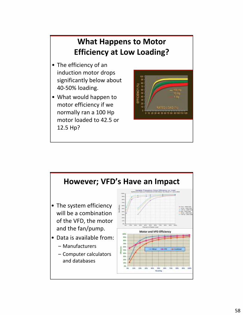
What Happens to Motor
Efficiency at Low Loading?
• The efficiency of an
induction motor drops
significantly below about
40-50% loading.
• What would happen to
motor efficiency if we
normally ran a 100 Hp
motor loaded to 42.5 or
12.5 Hp?
However; VFD’s Have an Impact
• The system efficiency
will be a combination
of the VFD, the motor
and the fan/pump.
• Data is available from:
– Manufacturers
– Computer calculators
and databases
59
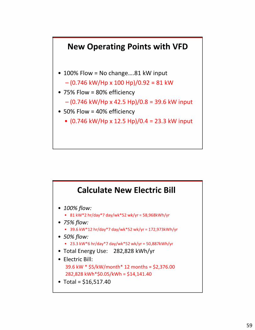
New Operating Points with VFD
• 100% Flow = No change….81 kW input
– (0.746 kW/Hp x 100 Hp)/0.92 = 81 kW
• 75% Flow = 80% efficiency
– (0.746 kW/Hp x 42.5 Hp)/0.8 = 39.6 kW input
• 50% Flow = 40% efficiency
• (0.746 kW/Hp x 12.5 Hp)/0.4 = 23.3 kW input
Calculate New Electric Bill
• 100% flow:• 81 kW*2 hr/day*7 day/wk*52 wk/yr = 58,968kWh/yr
• 75% flow:• 39.6 kW*12 hr/day*7 day/wk*52 wk/yr = 172,973kWh/yr
• 50% flow:• 23.3 kW*6 hr/day*7 day/wk*52 wk/yr = 50,887kWh/yr
• Total Energy Use: 282,828 kWh/yr
• Electric Bill:
39.6 kW * $5/kW/month* 12 months = $2,376.00
282,828 kWh*$0.05/kWh = $14,141.40
• Total = $16,517.40
60
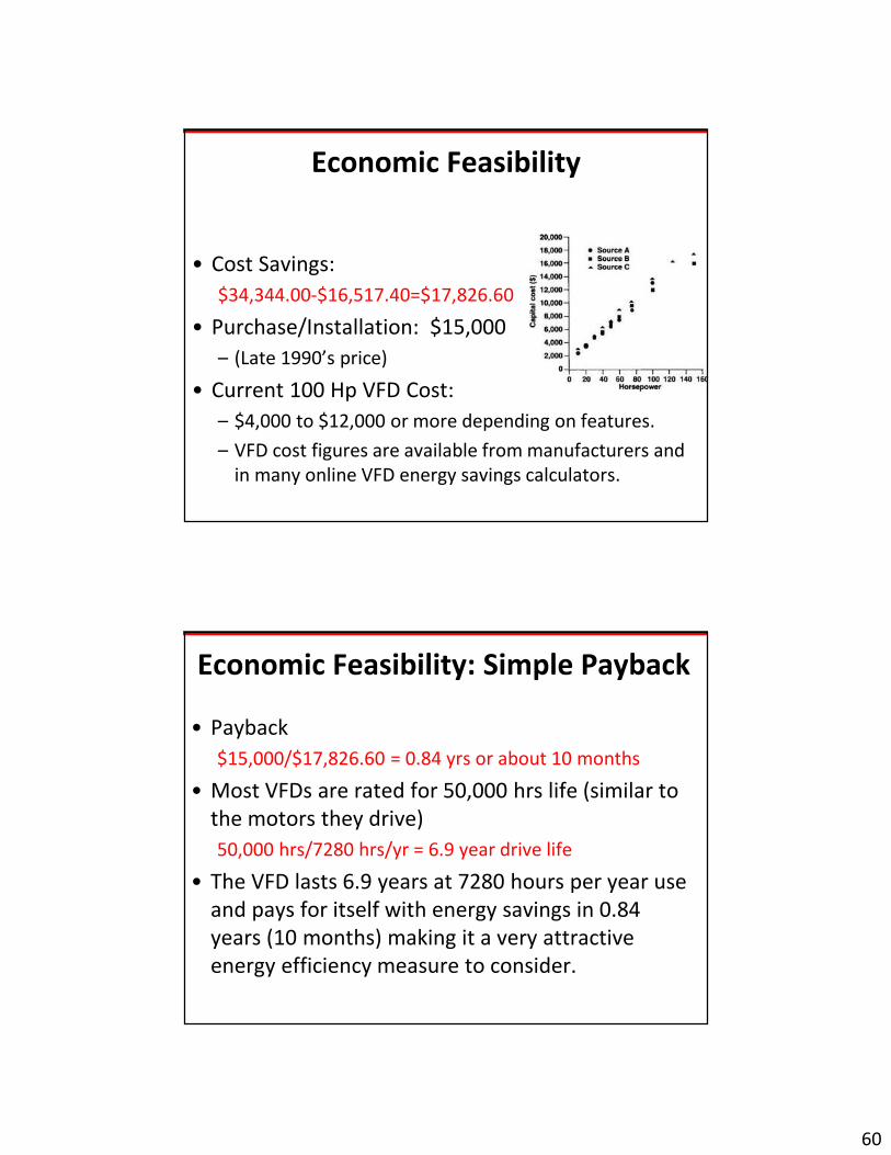
Economic Feasibility
• Cost Savings:
$34,344.00-$16,517.40=$17,826.60
• Purchase/Installation: $15,000
– (Late 1990’s price)
• Current 100 Hp VFD Cost:
– $4,000 to $12,000 or more depending on features.
– VFD cost figures are available from manufacturers and
in many online VFD energy savings calculators.
Economic Feasibility: Simple Payback
• Payback
$15,000/$17,826.60 = 0.84 yrs or about 10 months
• Most VFDs are rated for 50,000 hrs life (similar to
the motors they drive)
50,000 hrs/7280 hrs/yr = 6.9 year drive life
• The VFD lasts 6.9 years at 7280 hours per year use
and pays for itself with energy savings in 0.84
years (10 months) making it a very attractive
energy efficiency measure to consider.

61
Additional Resources
• Drives Mag
– www.drivesmag.com
• US Department of Energy
– Improving Motor & Drive System Performance: A
Sourcebook for Industry
• WI Focus on Energy
– Control Your Energy Costs with VFDs
• ComEd
– https://www.comed.com/sites/businesssavings/pages/
bsmotors.aspx
The End
Thank you for attending the course and thank
you to the course sponsor: