variable speed drives altivar 12 - schneider electric · variable speed drives altivar 12. ......
TRANSCRIPT
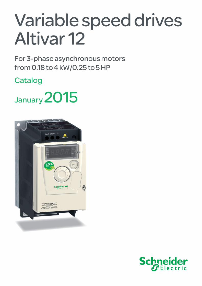
Variable speed drivesAltivar 12For 3-phase asynchronous motors from 0.18 to 4 kW/0.25 to 5 HP
Catalog
January 2015

Digi-Cat, a handy USB key for PC
Contact your local representative to get your own Digi-Cat
How can you fit a 6000-page catalog in your pocket ?Schneider Electric provides you with the complete set of industrial automation catalogs all on a handy USB key for PC or in an application for tablets
e-Library, the app for tablets
> Convenient to carry > Always up-to-date > Environmentally friendly > Easy-to-share format
> Go to the App Store and search for e-Library > or scan the QR code
If you have an iPad®:
> Go to the Google Play StoreTM and search for eLibrary > or scan the QR code
If you have an Android tablet:
1
Variable speed drivesAltivar 12
Contents
b Brochure . . . . . . . . . . . . . . . . . . . . . . . . . . . . . . . . . . . . . . . . . . . . . . . . . . page 2
IP 20 or IP 21 variable speed drives for asynchronous and synchronous motors selection guide . . . . . . . . . . . . . . . . . . . . . . . . . . . . . page 6
IP 54 or IP 55 variable speed drives for asynchronous and synchronous motors selection guide . . . . . . . . . . . . . . . . . . . . . . . . . . . . . page 8
Variable speed drives Altivar 61 Plus and Altivar 71 Plus selection guide . . . . . . . . . . . . . . . . . . . . . . . . . . . . . . . . . . . . . . . . . . . . . . . page 10
b Presentation of the Altivar 12 speed drives
v Presentation . . . . . . . . . . . . . . . . . . . . . . . . . . . . . . . . . . . . . . . . . . . . . . . page 12
v Applications . . . . . . . . . . . . . . . . . . . . . . . . . . . . . . . . . . . . . . . . . . . . . . . page 12
v Functions . . . . . . . . . . . . . . . . . . . . . . . . . . . . . . . . . . . . . . . . . . . . . . . . . page 13
v An optimized offer . . . . . . . . . . . . . . . . . . . . . . . . . . . . . . . . . . . . . . . . . . . page 13
v Complementary characteristics . . . . . . . . . . . . . . . . . . . . . . . . . . . . . . . . page 14
b References
v Drives with heatsink . . . . . . . . . . . . . . . . . . . . . . . . . . . . . . . . . . . . . . . . . page 16
v Drives on a base plate . . . . . . . . . . . . . . . . . . . . . . . . . . . . . . . . . . . . . . . page 17
v Accessories . . . . . . . . . . . . . . . . . . . . . . . . . . . . . . . . . . . . . . . . . . . . . . . page 18
v Configuration tools . . . . . . . . . . . . . . . . . . . . . . . . . . . . . . . . . . . . . . . . . . page 19
v Remote display terminals and associated cordsets . . . . . . . . . . . . . . . . . page 20
v Additional EMC input filters . . . . . . . . . . . . . . . . . . . . . . . . . . . . . . . . . . . . page 20
v Motor chokes . . . . . . . . . . . . . . . . . . . . . . . . . . . . . . . . . . . . . . . . . . . . . . page 21
v Ferrite suppressors . . . . . . . . . . . . . . . . . . . . . . . . . . . . . . . . . . . . . . . . . . page 21
v Modbus serial links . . . . . . . . . . . . . . . . . . . . . . . . . . . . . . . . . . . . . . . . . . page 21
v Replacement parts . . . . . . . . . . . . . . . . . . . . . . . . . . . . . . . . . . . . . . . . . . page 21
b Motor starters
v Applications . . . . . . . . . . . . . . . . . . . . . . . . . . . . . . . . . . . . . . . . . . . . . . . page 22
v Motor starters . . . . . . . . . . . . . . . . . . . . . . . . . . . . . . . . . . . . . . . . . . . . . . page 22
v Combinations . . . . . . . . . . . . . . . . . . . . . . . . . . . . . . . . . . . . . . . . . . . . . . page 23
b Product reference index . . . . . . . . . . . . . . . . . . . . . . . . . . . . . . . . . . . . . page 24
Make the most of your energy
Small
Reliable
Intuitive
High-performance
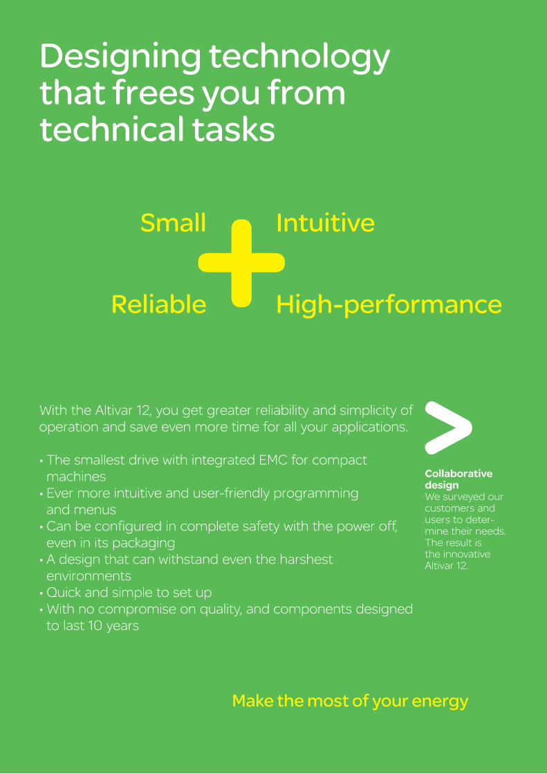
Designing technology that frees you from technical tasks
With the Altivar 12, you get greater reliability and simplicity of operation and save even more time for all your applications.
•ThesmallestdrivewithintegratedEMCforcompact machines•Evermoreintuitiveanduser-friendlyprogramming and menus•Canbeconfiguredincompletesafetywiththepoweroff,even in its packaging•Adesignthatcanwithstandeventheharshest environments•Quickandsimpletosetup•Withnocompromiseonquality,andcomponentsdesigned to last 10 years
Collaborative designWe surveyed our customers and users to deter-mine their needs. Theresultisthe innovative Altivar 12.
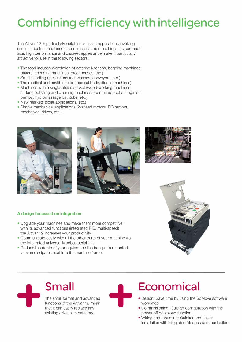
Combining efficiency with intelligenceThe Altivar 12 is particularly suitable for use in applications involving simple industrial machines or certain consumer machines. Its compact size, high performance and discreet appearance make it particularly attractive for use in the following sectors:
• The food industry (ventilation of catering kitchens, bagging machines, bakers’ kneading machines, greenhouses, etc.) • Small handling applications (car washes, conveyors, etc.)• The medical and health sector (medical beds, fitness machines)• Machines with a single-phase socket (wood-working machines, surface polishing and cleaning machines, swimming pool or irrigation pumps, hydromassage bathtubs, etc.)• New markets (solar applications, etc.)• Simple mechanical applications (2-speed motors, DC motors, mechanical drives, etc.)
A design focussed on integration
•Upgrade your machines and make them more competitive: with its advanced functions (integrated PID, multi-speed) the Altivar 12 increases your productivity •Communicate easily with all the other parts of your machine via the integrated universal Modbus serial link•Reduce the depth of your equipment: the baseplate mounted version dissipates heat into the machine frame
Small EconomicalThe small format and advanced functions of the Altivar 12 mean that it can easily replace any existing drive in its category.
•Design: Save time by using the SoMove software workshop•Commissioning: Quicker configuration with the power off download function•Wiring and mounting: Quicker and easier installation with integrated Modbus communication
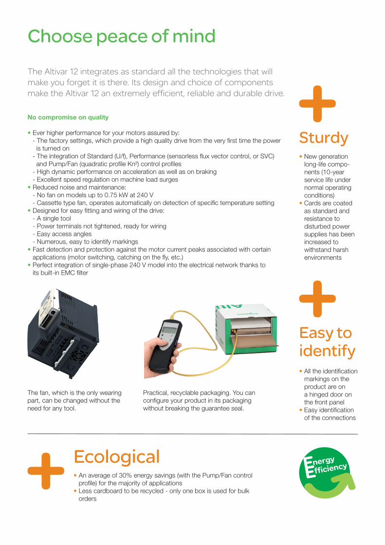
Choose peace of mindTheAltivar12integratesasstandardallthetechnologiesthatwillmake you forget it is there. Its design and choice of components make the Altivar 12 an extremely efficient, reliable and durable drive.
No compromise on quality
•Ever higher performance for your motors assured by: - The factory settings, which provide a high quality drive from the very first time the power is turned on - The integration of Standard (U/f), Performance (sensorless flux vector control, or SVC) and Pump/Fan (quadratic profile Kn²) control profiles - High dynamic performance on acceleration as well as on braking - Excellent speed regulation on machine load surges•Reduced noise and maintenance: - No fan on models up to 0.75 kW at 240 V - Cassette type fan, operates automatically on detection of specific temperature setting•Designed for easy fitting and wiring of the drive: - A single tool - Power terminals not tightened, ready for wiring - Easy access angles - Numerous, easy to identify markings•Fast detection and protection against the motor current peaks associated with certain applications (motor switching, catching on the fly, etc.)•Perfect integration of single-phase 240 V model into the electrical network thanks to its built-in EMC filter
The fan, which is the only wearing part, can be changed without the need for any tool.
Practical, recyclable packaging. You can configure your product in its packaging without breaking the guarantee seal.
Ecological
Sturdy
Easy to identify
•An average of 30% energy savings (with the Pump/Fan control profile) for the majority of applications•Less cardboard to be recycled - only one box is used for bulk orders
•New generation long-life compo- nents (10-year service life under normal operating conditions)• Cards are coated as standard and resistance to disturbed power supplies has been increased to withstand harsh environments
•All the identification markings on the product are on a hinged door on the front panel•Easy identification of the connections
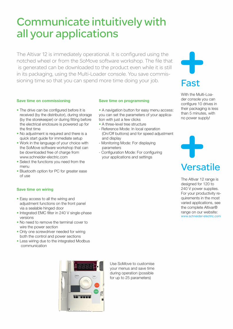
Communicate intuitively with all your applicationsTheAltivar12isimmediatelyoperational.Itisconfiguredusingthe notchedwheelorfromtheSoMovesoftwareworkshop.Thefilethat is generated can be downloaded to the product even while it is still initspackaging,usingtheMulti-Loaderconsole.Yousavecommis-sioning time so that you can spend more time doing your job.
Save time on commissioning
•The drive can be configured before it is received (by the distributor), during storage (by the storekeeper) or during fitting before the electrical enclosure is powered up for the first time•No adjustment is required and there is a quick start guide for immediate setup•Work in the language of your choice with the SoMove software workshop that can be downloaded free of charge from www.schneider-electric.com•Select the functions you need from the menu•Bluetooth option for PC for greater ease of use
Save time on programming
•A navigation button for easy menu access: you can set the parameters of your applica-tion with just a few clicks•A three-level tree structure- Reference Mode: In local operation (On/Off buttons) and for speed adjustment and display- Monitoring Mode: For displaying parameters- Configuration Mode: For configuring your applications and settings
Save time on wiring
• Easy access to all the wiring and adjustment functions on the front panel via a sealable hinged door• Integrated EMC filter in 240 V single-phase versions• No need to remove the terminal cover to wire the power section• Only one screwdriver needed for wiring both the control and power sections• Less wiring due to the integrated Modbus communication
Use SoMove to customise your menus and save time during operation (possible for up to 25 parameters)
Fast
Versatile
With the Multi-Loa-der console you can configure 10 drives in their packaging is less than 5 minutes, with no power supply!
The Altivar 12 range is designed for 120 to 240 V power supplies.For your productivity re-quirements in the most varied applications, see the complete Altivar® range on our website:www.schneider-electric.com
6 66 7
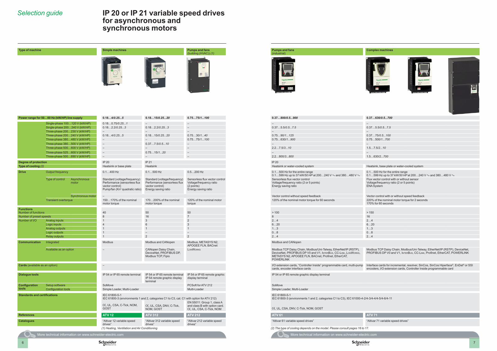
Selection guide IP 20 or IP 21 variable speed drives for asynchronous and synchronous motors
Type of machine Simple machines Pumps and fans(building (HVAC)) (1)
Pumps and fans(industrial)
Complex machines
Power range for 50…60 Hz (kW/HP) line supply 0 .18…4/0 .25 . . .5 0 .18…15/0 .25 . . .20 0 .75…75/1 . . .100 0 .37…800/0 .5 . . .900 0 .37…630/0 .5 . . .700
Single-phase 100…120 V (kW/HP) 0.18…0.75/0.25...1 – – – –Single-phase 200…240 V (kW/HP) 0.18…2.2/0.25...3 0.18…2.2/0.25...3 – 0.37…5.5/0.5...7.5 0.37…5.5/0.5...7.5Three-phase 200…230 V (kW/HP) – – – – –Three-phase 200…240 V (kW/HP) 0.18…4/0.25...5 0.18…15/0.25...20 0.75…30/1...40 0.75…90/1...125 0.37…75/0.5...100Three-phase 380…480 V (kW/HP) – – 0.75…75/1...100 0.75…630/1...900 0.75…500/1...700Three-phase 380…500 V (kW/HP) – 0.37…7.5/0.5...10 – – –Three-phase 500…600 V (kW/HP) – – – 2.2…7.5/3...10 1.5…7.5/2...10Three-phase 525…600 V (kW/HP) – 0.75…15/1...20 – – –Three-phase 500…690 V (kW/HP) – – – 2.2…800/3...800 1.5…630/2...700
Degree of protection IP 20 IP 21 IP 20Type of cooling (2) Heatsink or base plate Heatsink Heatsink or water-cooled system Heatsink, base plate or water-cooled system
Drive Output frequency 0.1…400 Hz 0.1…500 Hz 0.5…200 Hz 0.1…500 Hz for the entire range 0.1…599 Hz up to 37 kW/50 HP at 200…240 V a and 380…480 V a
0.1…500 Hz for the entire range 0.1…599 Hz up to 37 kW/50 HP at 200…240 V a and 380…480 V a
Type of control Asynchronous motor
Standard (voltage/frequency)Performance (sensorless flux vector control)Pump/fan (Kn2 quadratic ratio)
Standard (voltage/frequency)Performance (sensorless flux vector control)Energy saving ratio
Sensorless flux vector controlVoltage/frequency ratio (2 points)Energy saving ratio
Sensorless flux vector controlVoltage/frequency ratio (2 or 5 points) Energy saving ratio
Flux vector control with or without sensorVoltage/frequency ratio (2 or 5 points)ENA System
Synchronous motor – Vector control without speed feedback Vector control with or without speed feedbackTransient overtorque 150…170% of the nominal
motor torque170…200% of the nominal motor torque
120% of the nominal motor torque
120% of the nominal motor torque for 60 seconds 220% of the nominal motor torque for 2 seconds 170% for 60 seconds
FunctionsNumber of functions 40 50 50 > 100 > 150Number of preset speeds 8 16 7 8 16Number of I/O Analog inputs 1 3 2 2…4 2…4
Logic inputs 4 6 3 6…20 6…20Analog outputs 1 1 1 1…3 1…3Logic outputs 1 – – 0…8 0…8Relay outputs 1 2 2 2…4 2…4
Communication Integrated Modbus Modbus and CANopen Modbus, METASYS N2,APOGEE FLN, BACnet
Modbus and CANopen
Available as an option – CANopen Daisy Chain, DeviceNet, PROFIBUS DP, Modbus TCP, Fipio
LonWorks Modbus TCP Daisy Chain, Modbus/Uni-Telway, EtherNet/IP (RSTP), DeviceNet, PROFIBUS DP V0 and V1, InterBus, CC-LInk, LonWorks, METASYS N2, APOGEE FLN, BACnet, Profinet, EtherCAT, POWERLINK
Modbus TCP Daisy Chain, Modbus/Uni-Telway, EtherNet/IP (RSTP), DeviceNet, PROFIBUS DP V0 and V1, InterBus, CC-LInk, Profinet, EtherCAT, POWERLINK
Cards (available as an option) – I/O extension cards, “Controller Inside” programmable card, multi-pump cards, encoder interface cards
Interface cards for incremental, resolver, SinCos, SinCos Hiperface®, EnDat® or SSI encoders, I/O extension cards, Controller Inside programmable card
Dialogue tools IP 54 or IP 65 remote terminal IP 54 or IP 65 remote terminalIP 54 remote graphic display terminal
IP 54 or IP 65 remote graphic display terminal
IP 54 or IP 65 remote graphic display terminal
Configuration tools
Setup software SoMove PCSoft for ATV 212 SoMoveConfiguration tools Simple Loader, Multi-Loader Multi-Loader Simple Loader, Multi-Loader
Standards and certifications IEC 61800-5-1 IEC 61800-3 (environments 1 and 2, categories C1 to C3, cat. C1 with option for ATV 212)
IEC 61800-5-1 IEC 61800-3 (environments 1 and 2, categories C1 to C3), IEC 61000-4-2/4-3/4-4/4-5/4-6/4-11
e, UL, CSA, C-Tick, NOM, GOST
e, UL, CSA, DNV, C-Tick, NOM, GOST
EN 55011: Group 1, class A and class B with option card. e, UL, CSA, C-Tick, NOM
e, UL, CSA, DNV, C-Tick, NOM, GOST
References ATV 12 ATV 312 ATV 212 ATV 61 ATV 71Catalogues “Altivar 12 variable speed
drives”“Altivar 312 variable speed drives”
“Altivar 212 variable speed drives”
“Altivar 61 variable speed drives” “Altivar 71 variable speed drives”
(1) Heating, Ventilation and Air Conditioning (2) The type of cooling depends on the model. Please consult pages 16 to 17.
8 88 9
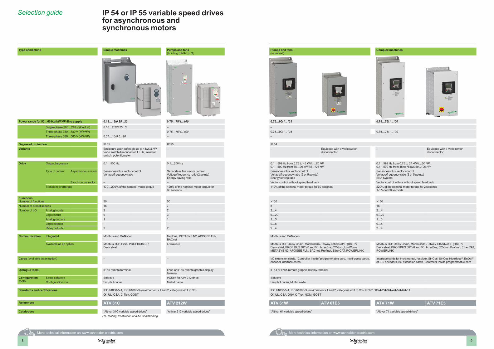
Type of machine Simple machines Pumps and fans (building (HVAC)) (1)
Pumps and fans (industrial)
Complex machines
Power range for 50…60 Hz (kW/HP) line supply 0 .18…15/0 .25 . . .20 0 .75…75/1 . . .100 0 .75…90/1 . . .125 0 .75…75/1 . . .100
Single-phase 200…240 V (kW/HP) 0.18…2.2/0.25...3 – –Three-phase 380…480 V (kW/HP) – 0.75…75/1...100 0.75…90/1...125 0.75…75/1...100Three-phase 380…500 V (kW/HP) 0.37…15/0.5...20 – –
Degree of protection IP 55 IP 55 IP 54Variants Enclosure user-definable up to 4 kW/5 HP:
Vario switch disconnector, LEDs, selector switch, potentiometer
– – Equipped with a Vario switch disconnector
– Equipped with a Vario switch disconnector
Drive Output frequency 0.1…500 Hz 0.1…200 Hz 0.1…599 Hz from 0.75 to 45 kW/1...60 HP0.1…500 Hz from 55…90 kW/75...125 HP
0.1…599 Hz from 0.75 to 37 kW/1...50 HP0.1…500 Hz from 45 to 75 kW/60...100 HP
Type of control Asynchronous motor Sensorless flux vector controlVoltage/frequency ratio
Sensorless flux vector controlVoltage/frequency ratio (2 points)Energy saving ratio
Sensorless flux vector controlVoltage/frequency ratio (2 or 5 points) Energy saving ratio
Sensorless flux vector controlVoltage/frequency ratio (2 or 5 points) ENA System
Synchronous motor – – Vector control without speed feedback Vector control with or without speed feedbackTransient overtorque 170…200% of the nominal motor torque 120% of the nominal motor torque for
60 seconds110% of the nominal motor torque for 60 seconds 220% of the nominal motor torque for 2 seconds
170% for 60 seconds
FunctionsNumber of functions 50 50 >100 >150Number of preset speeds 16 7 8 16Number of I/O Analog inputs 3 2 2…4 2…4
Logic inputs 6 3 6…20 6…20Analog outputs 1 1 1…3 1…3Logic outputs – – 0…8 0…8Relay outputs 2 2 2…4 2…4
Communication Integrated Modbus and CANopen Modbus, METASYS N2, APOGEE FLN,BACnet
Modbus and CANopen
Available as an option Modbus TCP, Fipio, PROFIBUS DP, DeviceNet
LonWorks Modbus TCP Daisy Chain, Modbus/Uni-Telway, EtherNet/IP (RSTP), DeviceNet, PROFIBUS DP V0 and V1, InterBus, CC-LInk, LonWorks, METASYS N2, APOGEE FLN, BACnet, Profinet, EtherCAT, POWERLINK
Modbus TCP Daisy Chain, Modbus/Uni-Telway, EtherNet/IP (RSTP), DeviceNet, PROFIBUS DP V0 and V1, InterBus, CC-LInk, Profinet, EtherCAT, POWERLINK
Cards (available as an option) – – I/O extension cards, “Controller Inside” programmable card, multi-pump cards, encoder interface cards
Interface cards for incremental, resolver, SinCos, SinCos Hiperface®, EnDat® or SSI encoders, I/O extension cards, Controller Inside programmable card
Dialogue tools IP 65 remote terminal IP 54 or IP 65 remote graphic display terminal
IP 54 or IP 65 remote graphic display terminal
Configuration tools
Setup software SoMove PCSoft for ATV 212 drive SoMoveConfiguration tool Simple Loader Multi-Loader Simple Loader, Multi-Loader
Standards and certifications IEC 61800-5-1, IEC 61800-3 (environments 1 and 2, categories C1 to C3) IEC 61800-5-1, IEC 61800-3 (environments 1 and 2, categories C1 to C3), IEC 61000-4-2/4-3/4-4/4-5/4-6/4-11 e, UL, CSA, C-Tick, GOST e, UL, CSA, DNV, C-Tick, NOM, GOST
References ATV 31C ATV 212W ATV 61W ATV 61E5 ATV 71W ATV 71E5
Catalogues “Altivar 31C variable speed drives” “Altivar 212 variable speed drives” “Altivar 61 variable speed drives” “Altivar 71 variable speed drives”(1) Heating, Ventilation and Air Conditioning
Selection guide IP 54 or IP 55 variable speed drives for asynchronous and synchronous motors
10 10
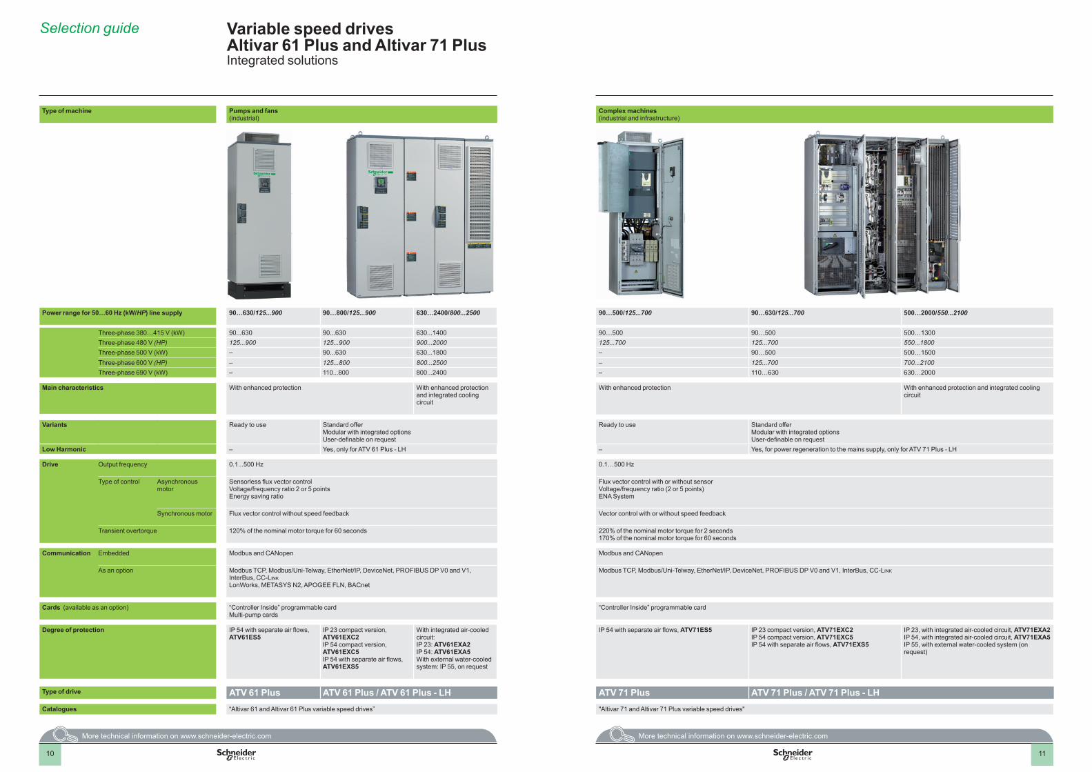
Type of machine Pumps and fans (industrial)
Complex machines (industrial and infrastructure)
Power range for 50…60 Hz (kW/HP) line supply 90…630/125 . . .900 90…800/125 . . .900 630…2400/800 . . .2500 90…500/125 . . .700 90…630/125 . . .700 500…2000/550 . . .2100
Three-phase 380…415 V (kW) 90...630 90...630 630...1400 90…500 90…500 500…1300Three-phase 480 V (HP) 125...900 125...900 900...2000 125...700 125...700 550...1800Three-phase 500 V (kW) – 90...630 630...1800 – 90…500 500…1500Three-phase 600 V (HP) – 125...800 800...2500 – 125...700 700...2100Three-phase 690 V (kW) – 110...800 800...2400 – 110…630 630…2000
Main characteristics With enhanced protection With enhanced protection and integrated cooling circuit
With enhanced protection With enhanced protection and integrated cooling circuit
Variants Ready to use Standard offerModular with integrated optionsUser-definable on request
Ready to use Standard offerModular with integrated optionsUser-definable on request
Low Harmonic – Yes, only for ATV 61 Plus - LH – Yes, for power regeneration to the mains supply, only for ATV 71 Plus - LH
Drive Output frequency 0.1...500 Hz 0.1…500 Hz
Type of control Asynchronous motor
Sensorless flux vector control Voltage/frequency ratio 2 or 5 pointsEnergy saving ratio
Flux vector control with or without sensor Voltage/frequency ratio (2 or 5 points)ENA System
Synchronous motor Flux vector control without speed feedback Vector control with or without speed feedback
Transient overtorque 120% of the nominal motor torque for 60 seconds 220% of the nominal motor torque for 2 seconds170% of the nominal motor torque for 60 seconds
Communication Embedded Modbus and CANopen Modbus and CANopen
As an option Modbus TCP, Modbus/Uni-Telway, EtherNet/IP, DeviceNet, PROFIBUS DP V0 and V1, InterBus, CC-LInkLonWorks, METASYS N2, APOGEE FLN, BACnet
Modbus TCP, Modbus/Uni-Telway, EtherNet/IP, DeviceNet, PROFIBUS DP V0 and V1, InterBus, CC-LInk
Cards (available as an option) “Controller Inside” programmable cardMulti-pump cards
“Controller Inside” programmable card
Degree of protection IP 54 with separate air flows, ATV61ES5
IP 23 compact version, ATV61EXC2IP 54 compact version, ATV61EXC5IP 54 with separate air flows, ATV61EXS5
With integrated air-cooled circuit:IP 23: ATV61EXA2IP 54: ATV61EXA5With external water-cooled system: IP 55, on request
IP 54 with separate air flows, ATV71ES5 IP 23 compact version, ATV71EXC2IP 54 compact version, ATV71EXC5IP 54 with separate air flows, ATV71EXS5
IP 23, with integrated air-cooled circuit, ATV71EXA2IP 54, with integrated air-cooled circuit, ATV71EXA5IP 55, with external water-cooled system (on request)
Type of drive ATV 61 Plus ATV 61 Plus / ATV 61 Plus - LH ATV 71 Plus ATV 71 Plus / ATV 71 Plus - LHCatalogues “Altivar 61 and Altivar 61 Plus variable speed drives” "Altivar 71 and Altivar 71 Plus variable speed drives"
Selection guide Variable speed drives Altivar 61 Plus and Altivar 71 PlusIntegrated solutions
11
12
Variable speed drivesAltivar 12
Presentation
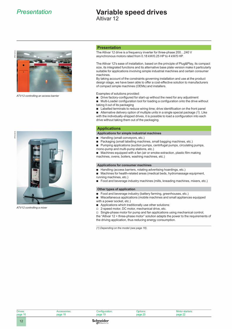
PresentationThe Altivar 12 drive is a frequency inverter for three-phase 200…240 V asynchronous motors rated from 0.18 kW/0.25 HP to 4 kW/5 HP.
The Altivar 12's ease of installation, based on the principle of Plug&Play, its compact size, its integrated functions and its alternative base plate version make it particularly suitable for applications involving simple industrial machines and certain consumer machines.By taking account of the constraints governing installation and use at the product design stage, we have been able to offer a cost-effective solution to manufacturers of compact simple machines (OEMs) and installers.
Examples of solutions provided: b Drive factory-configured for start-up without the need for any adjustment b Multi-Loader configuration tool for loading a configuration onto the drive without
taking it out of its packaging b Labelled terminals to reduce wiring time; drive identification on the front panel b Alternative delivery option of multiple units in a single special package (1). Like
with the individually-shipped drives, it is possible to load a configuration into each drive without taking them out of the packaging.
ApplicationsApplications for simple industrial machines b Handling (small conveyors, etc.) b Packaging (small labelling machines, small bagging machines, etc.) b Pumping applications (suction pumps, centrifugal pumps, circulating pumps,
mono-pump and multi-pump stations, etc.) b Machines equipped with a fan (air or smoke extraction, plastic film making
machines, ovens, boilers, washing machines, etc.)
Applications for consumer machines b Handling (access barriers, rotating advertising hoardings, etc.) b Machines for health-related areas (medical beds, hydromassage equipment,
running machines, etc.) b Food and beverage industry machines (mills, kneading machines, mixers, etc.)
Other types of application b Food and beverage industry (battery farming, greenhouses, etc.) b Miscellaneous applications (mobile machines and small appliances equipped
with a power socket, etc.) b Applications which traditionally use other solutions: v 2-speed motor, DC motor, mechanical drive, etc. v Single-phase motor for pump and fan applications using mechanical control;
the “Altivar 12 + three-phase motor” solution adapts the power to the requirements of the driving application, thus reducing energy consumption.
(1) Depending on the model (see page 16).
ATV12 controlling an access barrier
PF5
1341
2
ATV12 controlling a mixer
PF5
1341
8
Drives:page 16
Accessories:page 18
Configuration:page 19
Options:page 20
Motor starters:page 22
13
Presentation (continued) Variable speed drivesAltivar 12
FunctionsIn addition to the functions usually available on this type of drive, the Altivar 12 drive also features the following:
Application functions (1) b Switching between local control and control via the terminals b Motor control profiles: standard, performance and pump/fan b Frequency skip b Preset speeds b PID regulator b S ramp, U ramp, ramp switching b Freewheel stop, fast stop b Jog operation b Configuring the logic and analog I/O b Underload and overload detection b Viewing the state of the logic inputs on the drive display b Configuring how the parameters are displayed b Error log, etc.
Functions for pumping applications b Sleep/wake-up b PID functions b Protection functions : v Protection against overloads and overcurrents in continuous operation (pump
jamming) v Machine mechanical protection with control of operating direction v Protection of the installation by means of underload and overload detection
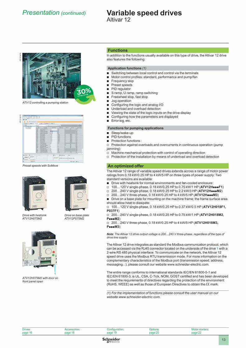
An optimized offerThe Altivar 12 range of variable speed drives extends across a range of motor power ratings from 0.18 kW/0.25 HP to 4 kW/5 HP on three types of power supply: Two standard versions are available:
b Drive with heatsink for normal environments and fan-cooled enclosure: v 100…120 V single-phase, 0.18 kW/0.25 HP to 0.75 kW/1 HP (ATV12HpppF1) v 200…240 V single-phase, 0.18 kW/0.25 HP to 2.2 kW/3 HP (ATV12HpppM2) v 200…240 V three-phase, 0.18 kW/0.25 HP to 4 kW/5 HP (ATV12HpppM3) b Drive on a base plate for mounting on the machine frame; the frame surface area
should allow heat to dissipate: v 100…120 V single-phase, 0.18 kW/0.25 HP to 0.37 kW/0.5 HP (ATV12H018F1,
P037F1) v 200…240 V single-phase, 0.18 kW/0.25 HP to 0.75 kW/1 HP (ATV12H018M2,
PpppM2) v 200…240 V three-phase, 0.18 kW/0.25 HP to 4 kW/5 HP (ATV12H018M3,
PpppM3)
Note: The Altivar 12 drive output voltage is 200…240 V three-phase, regardless of the type of drive line supply.
The Altivar 12 drive integrates as standard the Modbus communication protocol, which can be accessed via the RJ45 connector located on the underside of the drive 1 with a 2-wire RS 485 physical interface. To communicate on the network, the Altivar 12 speed drive uses the Modbus RTU transmission mode. For more information on the complementary characteristics of the Modbus port (transmission speed, address, messaging...), please consult our website www.schneider-electric.com.
The entire range conforms to international standards IEC/EN 61800-5-1 and IEC/EN 61800-3, is UL, CSA, C-Tick, NOM, GOST certified and has been developed to meet the requirements of directives regarding the protection of the environment (RoHS, WEEE) as well as those of European Directives to obtain the e mark.
(1) For the implementation of functions please consult the user manual on our website www.schneider-electric.com.
Drive with heatsink ATV12H075M2
Drive on base plate ATV12P075M2
PF
5134
19
ATV12 controlling a pumping station
Preset speeds with SoMove
PF
5134
15
Drives:page 16
Accessories:page 18
Configuration:page 19
Options:page 20
Motor starters:page 22
ATV12H075M2 with door on front panel open
1
14
Presentation (continued) Variable speed drivesAltivar 12
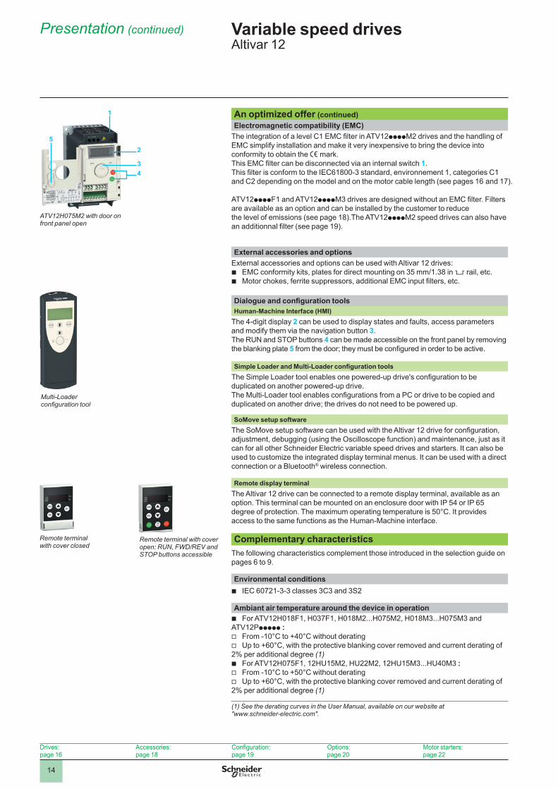
An optimized offer (continued)Electromagnetic compatibility (EMC)
The integration of a level C1 EMC filter in ATV12ppppM2 drives and the handling of EMC simplify installation and make it very inexpensive to bring the device into conformity to obtain the e mark.This EMC filter can be disconnected via an internal switch 1.This filter is conform to the IEC61800-3 standard, environnement 1, categories C1 and C2 depending on the model and on the motor cable length (see pages 16 and 17).
ATV12ppppF1 and ATV12ppppM3 drives are designed without an EMC filter. Filters are available as an option and can be installed by the customer to reduce the level of emissions (see page 18).The ATV12ppppM2 speed drives can also have an additionnal filter (see page 19).
External accessories and optionsExternal accessories and options can be used with Altivar 12 drives:
b EMC conformity kits, plates for direct mounting on 35 mm/1.38 in rail, etc. b Motor chokes, ferrite suppressors, additional EMC input filters, etc.
Dialogue and configuration toolsHuman-Machine Interface (HMI)
The 4-digit display 2 can be used to display states and faults, access parameters and modify them via the navigation button 3.The RUN and STOP buttons 4 can be made accessible on the front panel by removing the blanking plate 5 from the door; they must be configured in order to be active.
Simple Loader and Multi-Loader configuration toolsThe Simple Loader tool enables one powered-up drive's configuration to be duplicated on another powered-up drive.The Multi-Loader tool enables configurations from a PC or drive to be copied and duplicated on another drive; the drives do not need to be powered up.
SoMove setup softwareThe SoMove setup software can be used with the Altivar 12 drive for configuration, adjustment, debugging (using the Oscilloscope function) and maintenance, just as it can for all other Schneider Electric variable speed drives and starters. It can also be used to customize the integrated display terminal menus. It can be used with a direct connection or a Bluetooth® wireless connection.
Remote display terminalThe Altivar 12 drive can be connected to a remote display terminal, available as an option. This terminal can be mounted on an enclosure door with IP 54 or IP 65 degree of protection. The maximum operating temperature is 50°C. It provides access to the same functions as the Human-Machine interface.
Complementary characteristicsThe following characteristics complement those introduced in the selection guide on pages 6 to 9.
Environmental conditions b IEC 60721-3-3 classes 3C3 and 3S2
Ambiant air temperature around the device in operation b For ATV12H018F1, H037F1, H018M2...H075M2, H018M3...H075M3 and
ATV12Pppppp : v From -10°C to +40°C without derating v Up to +60°C, with the protective blanking cover removed and current derating of
2% per additional degree (1) b For ATV12H075F1, 12HU15M2, HU22M2, 12HU15M3...HU40M3 : v From -10°C to +50°C without derating v Up to +60°C, with the protective blanking cover removed and current derating of
2% per additional degree (1)
(1) See the derating curves in the User Manual, available on our website at "www.schneider-electric.com".
Multi-Loader configuration tool
Remote terminal with cover closed
Remote terminal with cover open: RUN, FWD/REV and STOP buttons accessible
Drives:page 16
Accessories:page 18
Configuration:page 19
Options:page 20
Motor starters:page 22
43
2
ATV12H075M2 with door on front panel open
5
1
15
Presentation (continued) Variable speed drivesAltivar 12
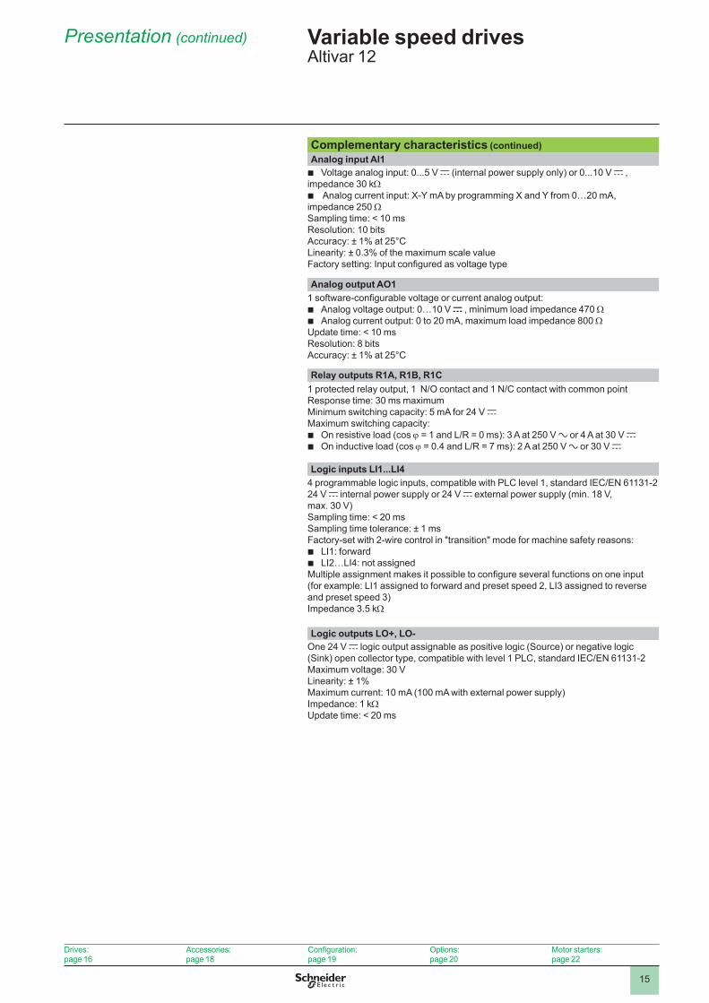
Complementary characteristics (continued)Analog input AI1 b Voltage analog input: 0...5 V c (internal power supply only) or 0...10 V c ,
impedance 30 kΩ b Analog current input: X-Y mA by programming X and Y from 0…20 mA,
impedance 250 ΩSampling time: < 10 msResolution: 10 bitsAccuracy: ± 1% at 25°CLinearity: ± 0.3% of the maximum scale valueFactory setting: Input configured as voltage type
Analog output AO11 software-configurable voltage or current analog output:
b Analog voltage output: 0…10 V c , minimum load impedance 470 Ω b Analog current output: 0 to 20 mA, maximum load impedance 800 Ω
Update time: < 10 msResolution: 8 bitsAccuracy: ± 1% at 25°C
Relay outputs R1A, R1B, R1C1 protected relay output, 1 N/O contact and 1 N/C contact with common pointResponse time: 30 ms maximumMinimum switching capacity: 5 mA for 24 V cMaximum switching capacity:
b On resistive load (cos j = 1 and L/R = 0 ms): 3 A at 250 V a or 4 A at 30 V c b On inductive load (cos j = 0.4 and L/R = 7 ms): 2 A at 250 V a or 30 V c
Logic inputs LI1 . . .LI44 programmable logic inputs, compatible with PLC level 1, standard IEC/EN 61131-224 V c internal power supply or 24 V c external power supply (min. 18 V, max. 30 V)Sampling time: < 20 msSampling time tolerance: ± 1 msFactory-set with 2-wire control in "transition" mode for machine safety reasons:
b LI1: forward b LI2…LI4: not assigned
Multiple assignment makes it possible to configure several functions on one input (for example: LI1 assigned to forward and preset speed 2, LI3 assigned to reverse and preset speed 3)Impedance 3.5 kΩ
Logic outputs LO+, LO-One 24 V c logic output assignable as positive logic (Source) or negative logic (Sink) open collector type, compatible with level 1 PLC, standard IEC/EN 61131-2Maximum voltage: 30 VLinearity: ± 1%Maximum current: 10 mA (100 mA with external power supply)Impedance: 1 kΩUpdate time: < 20 ms
Drives:page 16
Accessories:page 18
Configuration:page 19
Options:page 20
Motor starters:page 22
1616
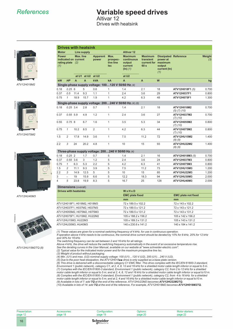
Drives with heatsinkMotor Line supply Altivar 12Power indicated on rating plate (1)
Max . line current (2)
Apparent power
Max . prospec-tive line Isc
Maximum continuous output current(In) (1)
Maximum transient current for 60 s
Dissipated power at maximum output current (In) (1)
Reference Weight(3)
at U1 at U2 at U2 at U2kW HP A A kVA kA A A W kgSingle-phase supply voltage: 100…120 V 50/60 Hz (4)
0.18 0.25 6 5 0.6 1 1.4 2.1 18 ATV12H018F1 (5) 0.7000.37 0.5 11.4 9.3 1.1 1 2.4 3.6 29 ATV12H037F1 0.8000.75 1 18.9 15.7 1.9 1 4.2 6.3 48 ATV12H075F1 1.300
Single-phase supply voltage: 200…240 V 50/60 Hz (4) (6)0.18 0.25 3.4 2.8 0.7 1 1.4 2.1 18 ATV12H018M2
(5) (7) (10)0.700
0.37 0.55 5.9 4.9 1.2 1 2.4 3.6 27 ATV12H037M2 (7) (10)
0.700
0.55 0.75 8 6.7 1.6 1 3.5 5.3 34 ATV12H055M2 (7) (10)
0.800
0.75 1 10.2 8.5 2 1 4.2 6.3 44 ATV12H075M2 (7) (10)
0.800
1.5 2 17.8 14.9 3.6 1 7.5 11.2 72 ATV12HU15M2 (8) (9)
1.400
2.2 3 24 20.2 4.8 1 10 15 93 ATV12HU22M2 (8) (9)
1.400
Three-phase supply voltage: 200…240 V 50/60 Hz (4)0.18 0.25 2 1.7 0.7 5 1.4 2.1 16 ATV12H018M3 (5) 0.7000.37 0.55 3.6 3 1.2 5 2.4 3.6 24 ATV12H037M3 0.8000.75 1 6.3 5.3 2.2 5 4.2 6.3 41 ATV12H075M3 0.8001.5 2 11.1 9.3 3.9 5 7.5 11.2 73 ATV12HU15M3 1.2002.2 3 14.9 12.5 5 5 10 15 85 ATV12HU22M3 1.2003 – 19 15.9 6.6 5 12.2 18.3 94 ATV12HU30M3 2.0004 5 23.8 19.9 8.3 5 16.7 25 128 ATV12HU40M3 2.000
Dimensions (overall)Drives with heatsinks W x H x D
EMC plate fixed EMC plate not fixedmm mm
ATV12H018F1, H018M2, H018M3 72 x 189.5 x 102.2 72 x 143 x 102.2ATV12H037F1, H037M2, H037M3 72 x 189.5 x 121.2 72 x 143 x 121.2ATV12H055M2, H075M2, H075M3 72 x 189.5 x 131.2 72 x 143 x 131.2ATV12H075F1, HU15M2, HU22M2 105 x 188.2 x 156.2 105 x 142 x 156.2ATV12HU15M3, HU22M3 105 x 189.3 x 131.2 105 x 143 x 131.2ATV12HU30M3, HU40M3 140 x 230.6 x 141.2 140 x 184 x 141.2
(1) These values are given for a nominal switching frequency of 4 kHz, for use in continuous operation. If operation above 4 kHz needs to be continuous, the nominal drive current should be derated by 10% for 8 kHz, 20% for 12 kHz and 30% for 16 kHz. The switching frequency can be set between 2 and 16 kHz for all ratings. Above 4 kHz, the drive will reduce the switching frequency automatically in the event of an excessive temperature rise. See the derating curves in the User Manual, available on our website at "www.schneider-electric.com".(2) Typical value for the indicated motor power and for the maximum prospective line Isc. (3) Weight of product without packaging.(4) Min. (U1) and max. (U2) nominal supply voltage: 100 (U1)…120 V (U2), 200 (U1)…240 V (U2).(5) Due to the poor heat dissipation, the ATV12H018pp drive is only supplied as a base plate version.(6) This drive is delivered with a disconnectable category C1 EMC filter. This drive complies with the IEC/EN 61800-3 standard, Environment 1 (public network), category C1, at 2, 4, 8, 12 and 16 kHz for a shielded motor cable length inferior or equal to 5 m.(7) Complies with the IEC/EN 61800-3 standard, Environment 1 (public network), category C2, from 2 to 12 kHz for a shielded motor cable length inferior or equal to 5 m; and at 2, 4, 8, 12 and 16 kHz for a shielded motor cable length inferior or equal to10 m.(8) Complies with the IEC/EN 61800-3 standard, Environment 1 (public network), category C2, from 4 to 16 kHz for a shielded motor cable length inferior or equal to 5 m; and at 2, 4 and 16 kHz for a shielded motor cable length inferior or equal to10 m.(9) Available in lots of 7: add TQ at the end of the reference. ATV12HU22M2 becomes ATV12HU22M2TQ .(10) Available in lots of 14: add TQ at the end of the reference. For example, ATV12H018M2 becomes ATV12H018M2TQ .
References Variable speed drivesAltivar 12Drives with heatsink
Presentation:page 12
Accessories:page 18
Configuration:page 19
Options:page 20
Motor starters:page 22
ATV12H018M2
PF0
8060
4F
ATV12H075M2
PF0
8060
7E
ATV12HU40M3
PF0
8061
9F
ATV12HU15M2TQ (8)
PF0
8065
1A
1717
Presentation:page 12
Accessories:page 18
Configuration:page 19
Options:page 20
Motor starters:page 22
References (continued) Variable speed drivesAltivar 12Drives on a base plate
ATV12PU22M3
PF0
8062
3D
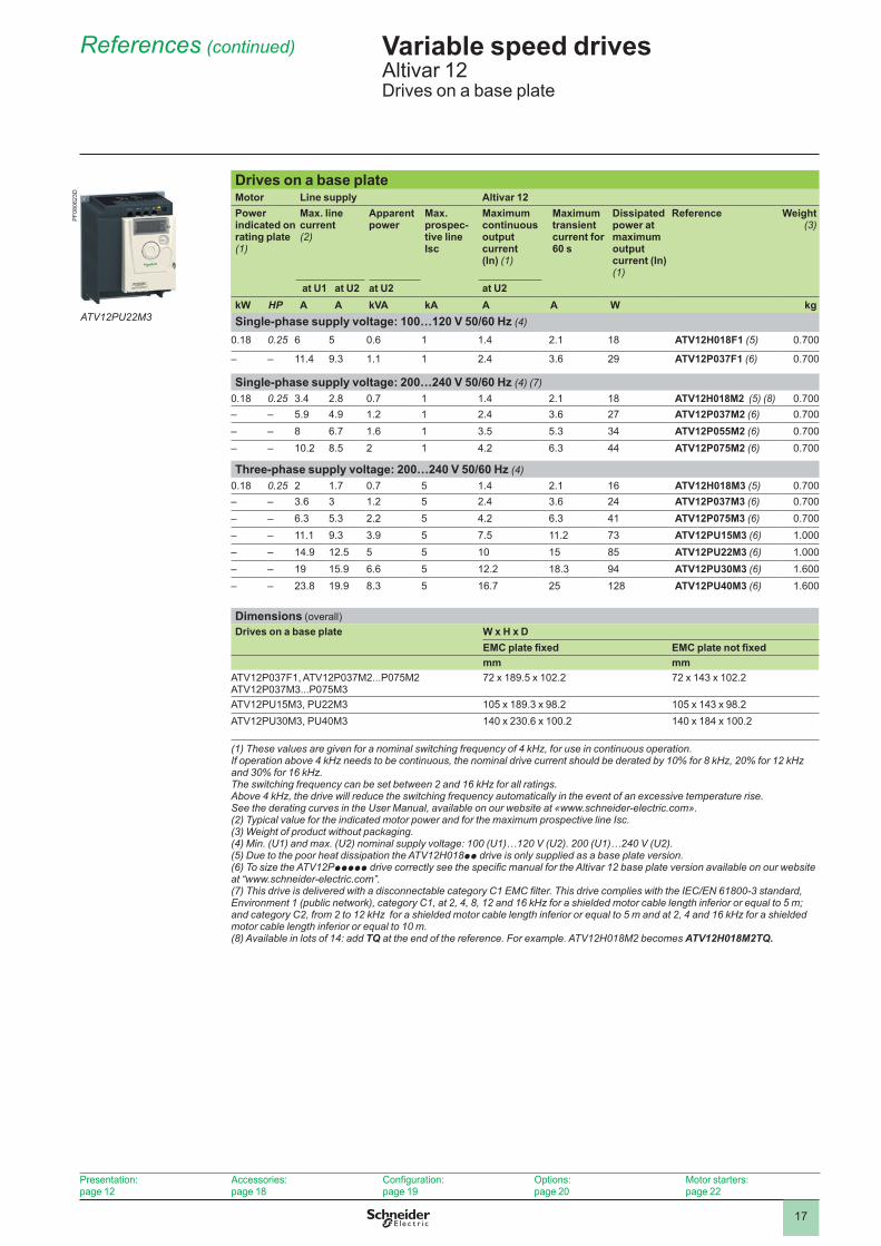
Drives on a base plateMotor Line supply Altivar 12Power indicated on rating plate (1)
Max . line current (2)
Apparent power
Max . prospec-tive line Isc
Maximum continuous output current(In) (1)
Maximum transient current for 60 s
Dissipated power at maximum output current (In) (1)
Reference Weight(3)
at U1 at U2 at U2 at U2kW HP A A kVA kA A A W kgSingle-phase supply voltage: 100…120 V 50/60 Hz (4)
0.18 0.25 6 5 0.6 1 1.4 2.1 18 ATV12H018F1 (5) 0.700
– – 11.4 9.3 1.1 1 2.4 3.6 29 ATV12P037F1 (6) 0.700
Single-phase supply voltage: 200…240 V 50/60 Hz (4) (7)0.18 0.25 3.4 2.8 0.7 1 1.4 2.1 18 ATV12H018M2 (5) (8) 0.700– – 5.9 4.9 1.2 1 2.4 3.6 27 ATV12P037M2 (6) 0.700– – 8 6.7 1.6 1 3.5 5.3 34 ATV12P055M2 (6) 0.700– – 10.2 8.5 2 1 4.2 6.3 44 ATV12P075M2 (6) 0.700
Three-phase supply voltage: 200…240 V 50/60 Hz (4)0.18 0.25 2 1.7 0.7 5 1.4 2.1 16 ATV12H018M3 (5) 0.700– – 3.6 3 1.2 5 2.4 3.6 24 ATV12P037M3 (6) 0.700– – 6.3 5.3 2.2 5 4.2 6.3 41 ATV12P075M3 (6) 0.700– – 11.1 9.3 3.9 5 7.5 11.2 73 ATV12PU15M3 (6) 1.000– – 14.9 12.5 5 5 10 15 85 ATV12PU22M3 (6) 1.000– – 19 15.9 6.6 5 12.2 18.3 94 ATV12PU30M3 (6) 1.600– – 23.8 19.9 8.3 5 16.7 25 128 ATV12PU40M3 (6) 1.600
Dimensions (overall)Drives on a base plate W x H x D
EMC plate fixed EMC plate not fixedmm mm
ATV12P037F1, ATV12P037M2...P075M2ATV12P037M3...P075M3
72 x 189.5 x 102.2 72 x 143 x 102.2
ATV12PU15M3, PU22M3 105 x 189.3 x 98.2 105 x 143 x 98.2ATV12PU30M3, PU40M3 140 x 230.6 x 100.2 140 x 184 x 100.2
(1) These values are given for a nominal switching frequency of 4 kHz, for use in continuous operation. If operation above 4 kHz needs to be continuous, the nominal drive current should be derated by 10% for 8 kHz, 20% for 12 kHz and 30% for 16 kHz. The switching frequency can be set between 2 and 16 kHz for all ratings. Above 4 kHz, the drive will reduce the switching frequency automatically in the event of an excessive temperature rise. See the derating curves in the User Manual, available on our website at «www.schneider-electric.com».(2) Typical value for the indicated motor power and for the maximum prospective line Isc. (3) Weight of product without packaging.(4) Min. (U1) and max. (U2) nominal supply voltage: 100 (U1)…120 V (U2). 200 (U1)…240 V (U2).(5) Due to the poor heat dissipation the ATV12H018pp drive is only supplied as a base plate version.(6) To size the ATV12Pppppp drive correctly see the specific manual for the Altivar 12 base plate version available on our website at “www.schneider-electric.com”.(7) This drive is delivered with a disconnectable category C1 EMC filter. This drive complies with the IEC/EN 61800-3 standard, Environment 1 (public network), category C1, at 2, 4, 8, 12 and 16 kHz for a shielded motor cable length inferior or equal to 5 m; and category C2, from 2 to 12 kHz for a shielded motor cable length inferior or equal to 5 m and at 2, 4 and 16 kHz for a shielded motor cable length inferior or equal to 10 m. (8) Available in lots of 14: add TQ at the end of the reference. For example. ATV12H018M2 becomes ATV12H018M2TQ .
1818
References (continued) Variable speed drivesAltivar 12Accessories
Presentation:page 12
Drives:page 16
Configuration:page 19
Options:page 20
Motor starters:page 22
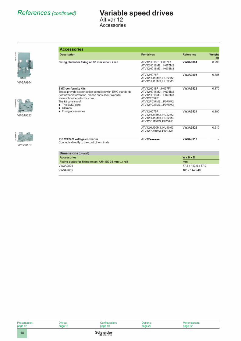
AccessoriesDescription For drives Reference Weight
kgFixing plates for fixing on 35 mm wide 5 rail ATV12H018F1, H037F1
ATV12H018M2…H075M2ATV12H018M3…H075M3
VW3A9804 0.290
ATV12H075F1ATV12HU15M2, HU22M2ATV12HU15M3, HU22M3
VW3A9805 0.385
EMC conformity kitsThese provide a connection compliant with EMC standards (for further information, please consult our website www.schneider-electric.com.)The kit consists of:
b The EMC plate b Clamps b Fixing accessories
ATV12H018F1, H037F1ATV12H018M2…H075M2ATV12H018M3…H075M3ATV12P037F1ATV12P037M2…P075M2ATV12P037M3…P075M3
VW3A9523 0.170
ATV12H075F1ATV12HU15M2, HU22M2ATV12HU15M3, HU22M3 ATV12PU15M3, PU22M3
VW3A9524 0.190
ATV12HU30M3, HU40M3ATV12PU30M3, PU40M3
VW3A9525 0.210
+15 V/+24 V voltage converterConnects directly to the control terminals
ATV12pppppp VW3A9317 –
Dimensions (overall)Accessories W x H x DFixing plates for fixing on an AM1 ED 35 mm rail mm
VW3A9804 77.5 x 143.6 x 37.9VW3A9805 105 x 144 x 40
VW3A9804
PF0
8067
0AP
F080
666A
VW3A9523
VW3A9524
PF0
8066
7A
1919
References (continued) Variable speed drivesAltivar 12Configuration tools
Presentation:page 12
Drives:page 16
Accessories:page 18
Options:page 20
Motor starters:page 22
Configuration toolsDescription For drives Reference Weight
kgSoMove lite setup software and associated accessories
SoMove lite setup softwareFor configuring, adjusting and debugging the Altivar 12 drive.Downloadable from our website “www.schneider-electric.com” or available on the “Description of the Motion & Drives Offer” DVD ROM VW3A8200.
ATV12pppppp (1) –
USB/RJ45 cableequipped with a USB connector and an RJ45 connector.For connecting a PC to the Altivar 12 drive.Length: 2.5 m
ATV12pppppp TCSMCNAM3M002P –
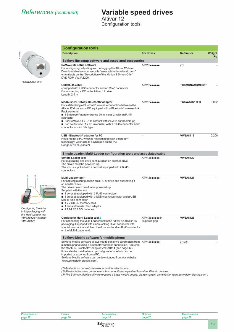
Modbus/Uni-Telway-Bluetooth® adaptorFor establishing a Bluetooth® wireless connection between the Altivar 12 drive and a PC equipped with a Bluetooth® wireless link.Pack contents:
b 1 Bluetooth® adaptor (range 20 m, class 2) with an RJ45 connector
b For SoMove : 1 x 0.1 m cordset with 2 RJ 45 connectors (2) b For TwidoSuite : 1 x 0.1 m cordset with 1 RJ 45 connector and 1
connector of mini DIN type
ATV12pppppp TCSWAAC13FB 0.032
USB - Bluetooth® adaptor for PCRequired for a PC which is not equipped with Bluetooth® technology. Connects to a USB port on the PC.Range of 10 m (class 2).
– VW3A8115 0.200
Simple Loader, Multi-Loader configuration tools and associated cableSimple Loader toolFor duplicating one drive configuration on another drive. The drives must be powered-up.The tool is supplied with a cordset equipped with 2 RJ45 connectors.
ATV12pppppp VW3A8120 –
Multi-Loader tool 1For copying a configuration on a PC or drive and duplicating it on another drive.The drives do not need to be powered-up.Supplied with the tool:
b 1 cordset equipped with 2 RJ45 connectors b 1 cordset equipped with a USB type A connector and a USB
Mini-B type connector b 1 x 2 GB SD memory card b 1 female/female RJ45 adaptor b 4 AA/LR6 1.5 V batteries
ATV12pppppp VW3A8121 –
Cordset for Multi-Loader tool 2For connecting the Multi-Loader tool to the Altivar 12 drive in its packaging. Equipped with a non-locking RJ45 connector with special mechanical catch on the drive end and an RJ45 connector on the Multi-Loader end.
ATV12pppppp in its packaging
VW3A8126 –
SoMove Mobile software for mobile phoneSoMove Mobile software allows you to edit drive parameters from a mobile phone using a Bluetooth® wireless connection. Requires the Modbus - Bluetooth® adaptor VW3A8114 (see page 17).It can also be used to back up configurations, which can be imported or exported from a PC.SoMove Mobile software can be downloaded from our website “www.schneider-electric.com”.
ATV12pppppp (1) (3) –
(1) Available on our website www.schneider-electric.com.(2) Also includes other components for connecting compatible Schneider Electric devices.(3) The SoMove Mobile software requires a basic mobile phone; please consult our website “www.schneider-electric.com”.
Configuring the drive in its packaging with the Multi-Loader tool VW3A8121+ cordset VW3A8126
1 2
PF1
0089
8C
TCSWAAC13FB
2020
References (continued) Variable speed drivesAltivar 12Remote display terminals, additional EMC input filters
Presentation:page 12
Drives:page 16
Accessories:page 18
Configuration:page 19
Motor starters:page 22
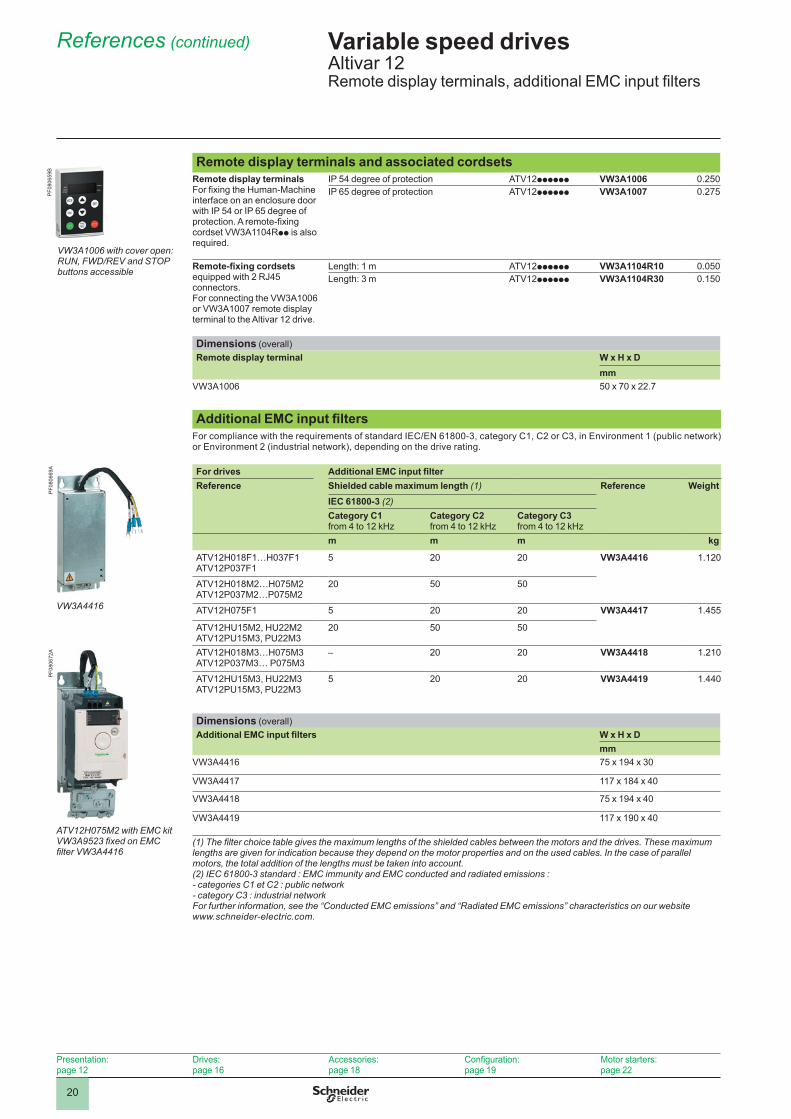
Remote display terminals and associated cordsetsRemote display terminalsFor fixing the Human-Machine interface on an enclosure door with IP 54 or IP 65 degree of protection. A remote-fixing cordset VW3A1104Rpp is also required.
IP 54 degree of protection ATV12pppppp VW3A1006 0.250IP 65 degree of protection ATV12pppppp VW3A1007 0.275
Remote-fixing cordsetsequipped with 2 RJ45 connectors.For connecting the VW3A1006 or VW3A1007 remote display terminal to the Altivar 12 drive.
Length: 1 m ATV12pppppp VW3A1104R10 0.050Length: 3 m ATV12pppppp VW3A1104R30 0.150
Dimensions (overall)Remote display terminal W x H x D
mmVW3A1006 50 x 70 x 22.7
Additional EMC input filtersFor compliance with the requirements of standard IEC/EN 61800-3, category C1, C2 or C3, in Environment 1 (public network) or Environment 2 (industrial network), depending on the drive rating.
For drives Additional EMC input filterReference Shielded cable maximum length (1) Reference Weight
IEC 61800-3 (2)Category C1from 4 to 12 kHz
Category C2from 4 to 12 kHz
Category C3from 4 to 12 kHz
m m m kg
ATV12H018F1…H037F1ATV12P037F1
5 20 20 VW3A4416 1.120
ATV12H018M2…H075M2ATV12P037M2…P075M2
20 50 50
ATV12H075F1 5 20 20 VW3A4417 1.455
ATV12HU15M2, HU22M2ATV12PU15M3, PU22M3
20 50 50
ATV12H018M3…H075M3ATV12P037M3… P075M3
– 20 20 VW3A4418 1.210
ATV12HU15M3, HU22M3ATV12PU15M3, PU22M3
5 20 20 VW3A4419 1.440
Dimensions (overall)Additional EMC input filters W x H x D
mmVW3A4416 75 x 194 x 30
VW3A4417 117 x 184 x 40
VW3A4418 75 x 194 x 40
VW3A4419 117 x 190 x 40
(1) The filter choice table gives the maximum lengths of the shielded cables between the motors and the drives. These maximum lengths are given for indication because they depend on the motor properties and on the used cables. In the case of parallel motors, the total addition of the lengths must be taken into account.(2) IEC 61800-3 standard : EMC immunity and EMC conducted and radiated emissions :- categories C1 et C2 : public network- category C3 : industrial networkFor further information, see the “Conducted EMC emissions” and “Radiated EMC emissions” characteristics on our websitewww.schneider-electric.com.
VW3A1006 with cover open: RUN, FWD/REV and STOP buttons accessible
PF0
8065
9B
VW3A4416
PF0
8066
9AP
F080
672A
ATV12H075M2 with EMC kit VW3A9523 fixed on EMC filter VW3A4416
2121
References (continued) Variable speed drivesAltivar 12Motor chokes, ferrite suppressors, Modbus serial links, and replacement parts
Presentation:page 12
Drives:page 16
Accessories:page 18
Configuration:page 19
Motor starters:page 22
VZ3V1302
PF0
8064
7A
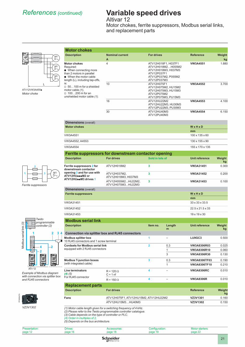
Motor chokesDescription Nominal current For drives Reference Weight
A kgMotor chokesRequired:
b When connecting more than 2 motors in parallel
b When the motor cable length (L), including tap-offs, is:
v 50…100 m for a shielded motor cable (1),
v 100…200 m for an unshielded motor cable (1).
4 ATV12H018F1, H037F1ATV12H018M2…H055M2ATV12H018M3, H037M3ATV12P037F1ATV12P037M2, P055M2ATV12P037M3
VW3A4551 1.880
10 ATV12H075F1ATV12H075M2, HU15M2ATV12H075M3, HU15M3ATV12P075M2ATV12P075M3, PU15M3
VW3A4552 3.700
16 ATV12HU22M2ATV12HU22M3, HU30M3ATV12PU22M3, PU30M3
VW3A4553 4.100
30 ATV12HU40M3ATV12PU40M3
VW3A4554 6.150
Dimensions (overall)Motor chokes W x H x D
mmVW3A4551 100 x 135 x 60
VW3A4552, A4553 130 x 155 x 90
VW3A4554 155 x 170 x 135
Ferrite suppressors for downstream contactor openingDescription For drives Sold in lots of Unit reference Weight
kgFerrite suppressors 2 for downstream contactor opening 3 and for use with ATV12HUpppM2 or ATV12HUppM3 drives 1
ATV12H018M2 3 VW3A31451 0.300
ATV12H037M2,ATV12H018M3, H037M3
3 VW3A31452 0.200
ATV12H055M2...HU22M2,ATV12H075M3...HU22M3
3 VW3A31453 0.100
Dimensions (overall)Ferrite suppressors W x H x D
mmVW3A31451 33 x 33 x 33.5
VW3A31452 22.5 x 21.5 x 33
VW3A31453 19 x 19 x 30
Modbus serial linkDescription Item no . Length
mUnit reference Weight
kgConnection via splitter box and RJ45 connectors
Modbus splitter box10 RJ45 connectors and 1 screw terminal
1 – LU9GC3 0.500
Cordsets for Modbus serial link equipped with 2 RJ45 connectors
2 0.3 VW3A8306R03 0.0251 VW3A8306R10 0.0603 VW3A8306R30 0.130
Modbus T-junction boxes (with integrated cable)
3 0.3 VW3A8306TF03 0.1901 VW3A8306TF10 0.210
Line terminators (4) (5)For RJ45 connector
R = 120 ΩC = 1 nf
4 – VW3A8306RC 0.010
R = 150 Ω 4 – VW3A8306R 0.010
Replacement partsDescription For drives Reference Weight
kgFans ATV12H075F1, ATV12HU15M2, ATV12HU22M2 VZ3V1301 0.160
ATV12HU15M3…HU40M3 VZ3V1302 0.150
(1) Motor cable length given for a switching frequency of 4 kHz.(2) Please refer to the Twido programmable controller catalogue.(3) Cable depends on the type of controller or PLC.(4) Order in multiples of 2.(5) Depends on the bus architecture.
M1 3
M1 3
M1 3
L
Motor chokeATV12VW3A455p
4 22
21 3
ATV 12
4
Twido programmable controller (2)
Mod
bus
seria
l lin
k (3
)
Example of Modbus diagram with connection via splitter box and RJ45 connectors
M1 3
1 3
2
Ferrite suppressors
22
ApplicationsThe proposed combinations can:
b Protect people and equipment (when a short-circuit occurs) b Maintain protection upstream of the drive in the event of a short-circuit on the
power stage
Two types of combination are possible: b Drive + circuit-breaker: Minimum combination b Drive + circuit-breaker + contactor: Minimum combination with contactor when a
control circuit is needed
Motor startersStandard power ratings of three-phase 4-pole 50/60 Hz motors(2)
Variable speed drive
Combination with control circuit(circuit-breaker + contactor)Minimum combination(circuit-breaker only)
TeSys contactor(1)TeSys motor
circuit-breaker (3)
Operating range or rating
Maximum short-circuit current Icu
Modular circuit-breaker (4)
kW HP A kAM1 A1 Q1 KM1Single-phase supply voltage: 100…120 V 50/60 Hz (5)
0.18 0.25 ATV12H018F1 GV2ME14 6…10 > 100 LC1K09GV2L10 6.3 > 1002-pole C60N 10 10
0.37 0.5 ATV12p037F1 GV2ME16 9…14 > 100 LC1K12GV2L16 14 > 1002-pole C60N 16 10
0.75 1 ATV12H075F1 GV2ME21 17…23 50 LC1D25GV2L22 25 > 502-pole C60N 20 10
Single-phase supply voltage: 200…240 V 50/60 Hz (5)0.18 0.25 ATV12H018M2 GV2ME08 2.5…4 > 100 LC1K09
GV2L08 4 > 1002-pole C60N 6 10
0.37 0.55 ATV12p037M2 GV2ME14 6…10 > 100 LC1K09GV2L10 6.3 > 1002-pole C60N 10 10
0.55 0.75 ATV12p055M2 GV2ME14 6...10 > 100 LC1K09GV2L14 10 > 1002-pole C60N 10 10
0.75 1 ATV12p075M2 GV2ME16 9...14 > 100 LC1K12GVL16 14 > 1002-pole C60N 16 10
1.5 2 ATV12HU15M2 GV2ME21 17…23 50 LC1D18GV2L20 18 > 1002-pole C60N 20 10
2.2 3 ATV12HU22M2 GV2ME32 24...32 50 LC1D25GV2L22 25 502-pole C60N 32 10
(1) For a complete list of references for TeSys contactors, please refer to the "Motor starter solutions - Control and protection components" and "Motor starters up to 150 A" catalogues or visit "www.schneider-electric.com".(2) Motor power indicated for combination with an ATV12Hppppp drive with the same rating. For combination with an ATV12Pppppp drive, refer to the specific manual for the Altivar 12 base plate version, available on our website at “www.schneider-electric.com”.(3) TeSys motor circuit-breakers: - GV2 MEpp: Thermal magnetic motor circuit-breakers with pushbutton control- GV2 Lpp: Magnetic motor circuit-breakers with control by rotary knob(4) 2-pole C60N modular circuit-breaker(5) Can be integrated in devices connected to a power socket:- If the line current is y 16 A, connection to a single-phase power socket, 10/16 A 250 V z- If the line current is > 16 A, connection to a single-phase power socket conforming to standard IEC 60309
Combinations for customer assembly
Variable speed drivesAltivar 12Motor starters: Single-phase supply voltages 100…120 V and 200…240 V
Presentation:page 12
Drives:page 16
Accessories:page 18
Configuration:page 19
Options:page 20
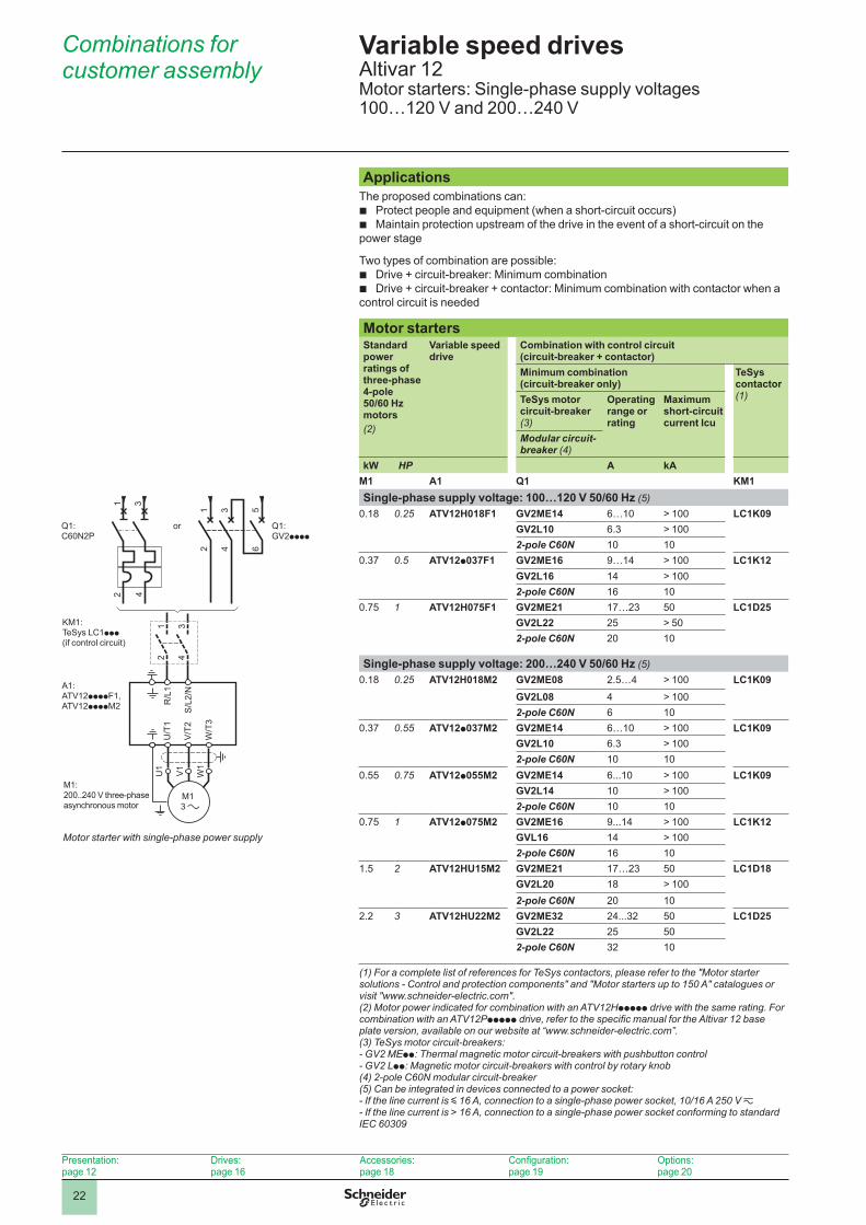
Motor starter with single-phase power supply
2 4
1 3
W/T
3
U/T
1
V/T
2
R/L
1
S/L
2/N
U1
W1
V1
M1 3
2 4
2 4
6
1 3 5
1 3
Q1: C60N2P
KM1: TeSys LC1ppp(if control circuit)
A1: ATV12ppppF1, ATV12ppppM2
Q1: GV2pppp
M1: 200..240 V three-phase asynchronous motor
or
23
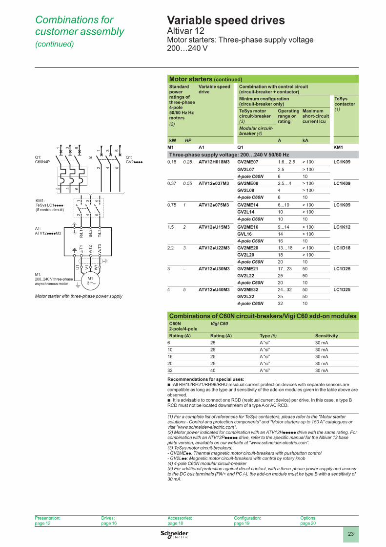
Combinations for customer assembly (continued)
Variable speed drivesAltivar 12Motor starters: Three-phase supply voltage 200…240 V
Motor starters (continued)Standard power ratings of three-phase 4-pole 50/60 Hz Hz motors (2)
Variable speed drive
Combination with control circuit(circuit-breaker + contactor)Minimum configuration(circuit-breaker only)
TeSys contactor(1)TeSys motor
circuit-breaker(3)
Operating range or rating
Maximum short-circuit current Icu
Modular circuit-breaker (4)
kW HP A kAM1 A1 Q1 KM1Three-phase supply voltage: 200…240 V 50/60 Hz
0.18 0.25 ATV12H018M3 GV2ME07 1.6…2.5 > 100 LC1K09GV2L07 2.5 > 1004-pole C60N 6 10
0.37 0.55 ATV12p037M3 GV2ME08 2.5…4 > 100 LC1K09GV2L08 4 > 1004-pole C60N 6 10
0.75 1 ATV12p075M3 GV2ME14 6...10 > 100 LC1K09GV2L14 10 > 1004-pole C60N 10 10
1.5 2 ATV12pU15M3 GV2ME16 9...14 > 100 LC1K12GVL16 14 > 1004-pole C60N 16 10
2.2 3 ATV12pU22M3 GV2ME20 13…18 > 100 LC1D18GV2L20 18 > 1004-pole C60N 20 10
3 – ATV12pU30M3 GV2ME21 17...23 50 LC1D25GV2L22 25 504-pole C60N 20 10
4 5 ATV12pU40M3 GV2ME32 24...32 50 LC1D25GV2L22 25 504-pole C60N 32 10
Combinations of C60N circuit-breakers/Vigi C60 add-on modulesC60N2-pole/4-pole
Vigi C60
Rating (A) Rating (A) Type (5) Sensitivity6 25 A “si” 30 mA10 25 A “si” 30 mA16 25 A “si” 30 mA20 25 A “si” 30 mA32 40 A “si” 30 mA
Recommendations for special uses: b All RH10/RH21/RH99/RHU residual current protection devices with separate sensors are
compatible as long as the type and sensitivity of the add-on modules given in the table above are observed.
b It is advisable to connect one RCD (residual current device) per drive. In this case, a type B RCD must not be located downstream of a type A or AC RCD.
(1) For a complete list of references for TeSys contactors, please refer to the "Motor starter solutions - Control and protection components" and "Motor starters up to 150 A" catalogues or visit "www.schneider-electric.com".(2) Motor power indicated for combination with an ATV12Hppppp drive with the same rating. For combination with an ATV12Pppppp drive, refer to the specific manual for the Altivar 12 base plate version, available on our website at “www.schneider-electric.com”.(3) TeSys motor circuit-breakers: - GV2MEpp: Thermal magnetic motor circuit-breakers with pushbutton control- GV2Lpp: Magnetic motor circuit-breakers with control by rotary knob(4) 4-pole C60N modular circuit-breaker(5) For additional protection against direct contact, with a three-phase power supply and access to the DC bus terminals (PA/+ and PC /-), the add-on module must be type B with a sensitivity of 30 mA.
2 4
1
653
W/T
3
U/T
1
V/T
2
R/L
1
S/L
2
T/L3
U1
W1
V1
M1 3
2 4
1 3
65
2 4
1 3
65
Motor starter with three-phase power supply
Q1: C60N4P
KM1: TeSys LC1pppp(if control circuit)
A1: ATV12ppppM3
Q1: GV2pppp
M1: 200..240 V three-phase asynchronous motor
or
Presentation:page 12
Drives:page 16
Accessories:page 18
Configuration:page 19
Options:page 20
24
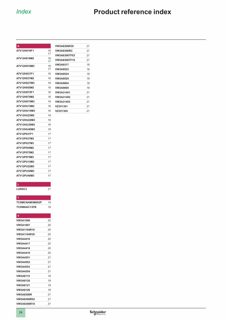
AATV12H018F1 16
17
ATV12H018M2 16 17
ATV12H018M3 16 17
ATV12H037F1 16
ATV12H037M2 16
ATV12H037M3 16
ATV12H055M2 16
ATV12H075F1 16
ATV12H075M2 16
ATV12H075M3 16
ATV12HU15M2 16
ATV12HU15M3 16
ATV12HU22M2 16
ATV12HU22M3 16
ATV12HU30M3 16
ATV12HU40M3 16
ATV12P037F1 17
ATV12P037M2 17
ATV12P037M3 17
ATV12P055M2 17
ATV12P075M2 17
ATV12P075M3 17
ATV12PU15M3 17
ATV12PU22M3 17
ATV12PU30M3 17
ATV12PU40M3 17
LLU9GC3 21
TTCSMCNAM3M002P 19
TCSWAAC13FB 19
VVW3A1006 20
VW3A1007 20
VW3A1104R10 20
VW3A1104R30 20
VW3A4416 20
VW3A4417 20
VW3A4418 20
VW3A4419 20
VW3A4551 21
VW3A4552 21
VW3A4553 21
VW3A4554 21
VW3A8115 19
VW3A8120 19
VW3A8121 19
VW3A8126 19
VW3A8306R 21
VW3A8306R03 21
VW3A8306R10 21
VW3A8306R30 21
VW3A8306RC 21
VW3A8306TF03 21
VW3A8306TF10 21
VW3A9317 18
VW3A9523 18
VW3A9524 18
VW3A9525 18
VW3A9804 18
VW3A9805 18
VW3A31451 21
VW3A31452 21
VW3A31453 21
VZ3V1301 21
VZ3V1302 21
Product reference indexIndex


DIA
2ED
2130
101E
N
January 2015 - V2.0
The information provided in this documentation contains general descriptions and/or technical characteristics of the performance of the products contained herein. This documentation is not intended as a substitute for and is not to be used for determining suitability or reliability of these products for specific user applications. It is the duty of any such user or integrator to perform the appropriate and complete risk analysis, evaluation and testing of the products with respect to the relevant specific application or use thereof. Neither Schneider Electric nor any of its affiliates or subsidiaries shall be responsible or liable for misuse of the information contained herein.
Design: Schneider ElectricPhotos: Schneider Electric
Head Office35, rue Joseph MonierF-92500 Rueil-MalmaisonFrance
Schneider Electric Industries SAS www.schneider-electric.com/drives
Altivar drives