contents variable speed drives altivar 71 -...
TRANSCRIPT
1
Variable speed drives Altivar 71
Contents Contents
Selection guide . . . . . . . . . . . . . . . . . . . . . . . . . . . . . . . . . . . . . . . . . . . . . . .page 2
Presentation . . . . . . . . . . . . . . . . . . . . . . . . . . . . . . . . . . . . . . . . . . . . . . . . page 4
Variable speed drives
characteristics . . . . . . . . . . . . . . . . . . . . . . . . . . . . . . . . . . . . . . . . . . . . page 10operation . . . . . . . . . . . . . . . . . . . . . . . . . . . . . . . . . . . . . . . . . . . . . . . . page 18UL type 1/IP 20 and UL type 12/IP 54 variable speed drives . . . . . . . . . . page 22accessories for UL type 1/IP 20 and UL type 12/IP 54 variable speed drives. . . . . . . . . . . . . . . . . . . . . . . . . . . . . . . . . . . . . . . . . page 26pre-equipped IP 54 fl oor-standing enclosure kit . . . . . . . . . . . . . . . . . . . page 39IP 23 or IP 54 fl oor-standing enclosure compact version . . . . . . . . . . . . page 52UL Type 12/IP 54 drives with Vario . . . . . . . . . . . . . . . . . . . . . . . . . . . . . page 78IP 54 fl oor-standing enclosure with separate air fl ows . . . . . . . . . . . . . . page 86
Options
dialogue . . . . . . . . . . . . . . . . . . . . . . . . . . . . . . . . . . . . . . . . . . . . . . . . page 108encoder interface cards . . . . . . . . . . . . . . . . . . . . . . . . . . . . . . . . . . . . page 110I/O extension cards . . . . . . . . . . . . . . . . . . . . . . . . . . . . . . . . . . . . . . . page 114“Controller Inside” programmable card . . . . . . . . . . . . . . . . . . . . . . . . . page 116communication buses and networks . . . . . . . . . . . . . . . . . . . . . . . . . . page 124resistance braking units . . . . . . . . . . . . . . . . . . . . . . . . . . . . . . . . . . . page 134braking resistors . . . . . . . . . . . . . . . . . . . . . . . . . . . . . . . . . . . . . . . . . . page 136hoist resistors . . . . . . . . . . . . . . . . . . . . . . . . . . . . . . . . . . . . . . . . . . . . page 138network braking units . . . . . . . . . . . . . . . . . . . . . . . . . . . . . . . . . . . . . . page 148reduction of current harmonics:- DC chokes . . . . . . . . . . . . . . . . . . . . . . . . . . . . . . . . . . . . . . . . . . . . . page 155- line chokes . . . . . . . . . . . . . . . . . . . . . . . . . . . . . . . . . . . . . . . . . . . . . page 160- passive fi lters . . . . . . . . . . . . . . . . . . . . . . . . . . . . . . . . . . . . . . . . . . . page 162- additional EMC input fi lters . . . . . . . . . . . . . . . . . . . . . . . . . . . . . . . . . page 168output fi lters:- motor chokes . . . . . . . . . . . . . . . . . . . . . . . . . . . . . . . . . . . . . . . . . . . page 172- sinus fi lters . . . . . . . . . . . . . . . . . . . . . . . . . . . . . . . . . . . . . . . . . . . . . page 175
Combinations of variable speed drives and options. . . . . . . . . . . . . . page 176
Dimensions . . . . . . . . . . . . . . . . . . . . . . . . . . . . . . . . . . . . . . . . . . . . . . page 188
Schemes . . . . . . . . . . . . . . . . . . . . . . . . . . . . . . . . . . . . . . . . . . . . . . . . . page 218
Motor starters . . . . . . . . . . . . . . . . . . . . . . . . . . . . . . . . . . . . . . . . . . . . . page 242
Mounting recommendations . . . . . . . . . . . . . . . . . . . . . . . . . . . . . . . . . page 250
Combinations of functions and applications. . . . . . . . . . . . . . . . . . . . page 266
Functions . . . . . . . . . . . . . . . . . . . . . . . . . . . . . . . . . . . . . . . . . . . . . . . . page 268
Compatibility table for functions . . . . . . . . . . . . . . . . . . . . . . . . . . . . . page 300
PowerSuite software workshop . . . . . . . . . . . . . . . . . . . . . . . . . . . . . . page 302
Communication via ModBus TCP Network . . . . . . . . . . . . . . . . . . . . . page 306
Communication via Fipio bus . . . . . . . . . . . . . . . . . . . . . . . . . . . . . . . . page 312
Communication via Modbus serial link . . . . . . . . . . . . . . . . . . . . . . . . page 316
Communication via Modbus Plus network . . . . . . . . . . . . . . . . . . . . . page 320
Communication via Uni-Telway serial link . . . . . . . . . . . . . . . . . . . . . . page 324
Communication gateways LUF P . . . . . . . . . . . . . . . . . . . . . . . . . . . . . page 326
Communication gateway LA9 P307 . . . . . . . . . . . . . . . . . . . . . . . . . . . page 330
b
b
v
v
v
v
v
v
v
v
b
v
v
v
v
v
v
v
v
v
v
v
b
b
b
b
b
b
b
b
b
b
b
b
b
b
b
b
300
(1)
Functions
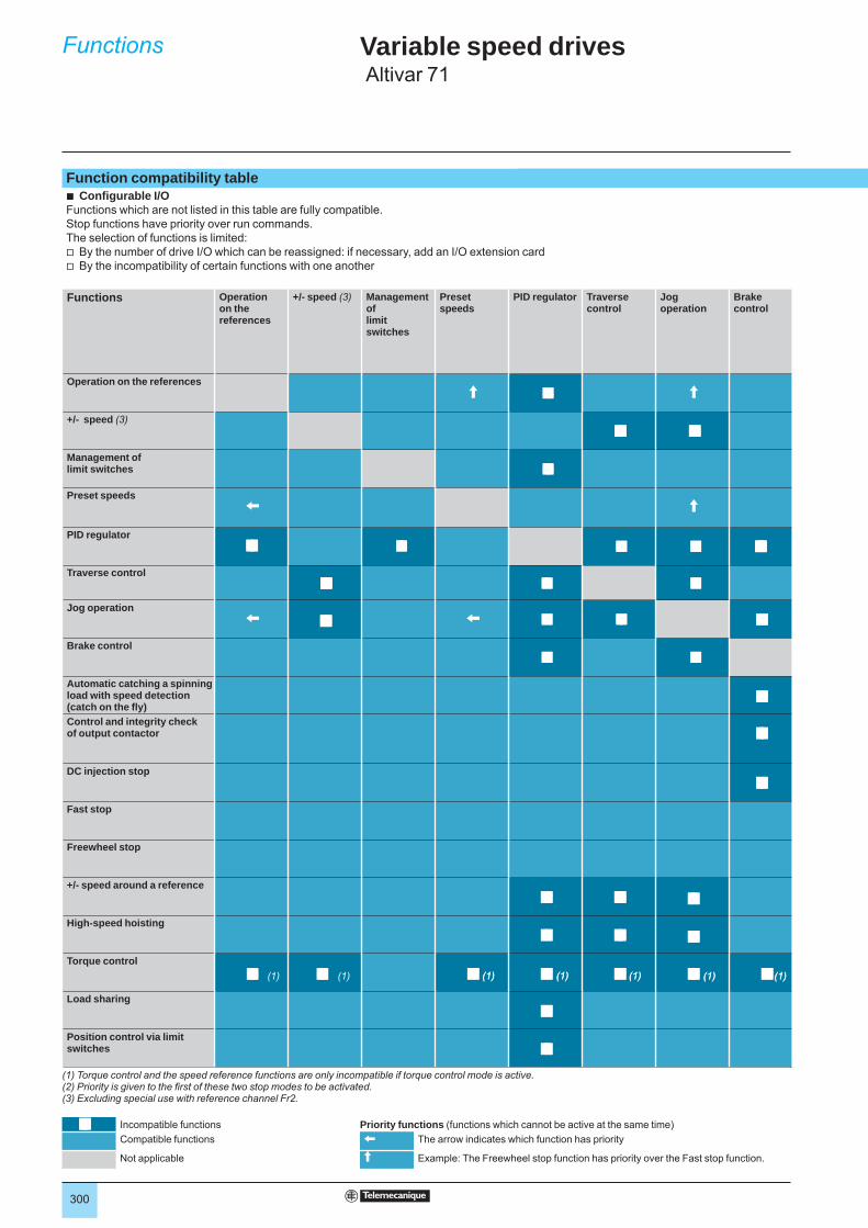
Function compatibility tableb Confi gurable I/OFunctions which are not listed in this table are fully compatible.Stop functions have priority over run commands.The selection of functions is limited:v By the number of drive I/O which can be reassigned: if necessary, add an I/O extension cardv By the incompatibility of certain functions with one another
Functions Operation
on the references
+/- speed (3) Management oflimit switches
Preset speeds
PID regulator Traversecontrol
Jogoperation
Brakecontrol
Operation on the referencesA A
+/- speed (3)
Management of limit switches
Preset speedsX A
PID regulator
Traverse control
Jog operationX X
Brake control
Automatic catching a spinning load with speed detection (catch on the fl y)Control and integrity check of output contactor
DC injection stop
Fast stop
Freewheel stop
+/- speed around a reference
High-speed hoisting
Torque control
Load sharing
Position control via limit switches
(1) Torque control and the speed reference functions are only incompatible if torque control mode is active.(2) Priority is given to the fi rst of these two stop modes to be activated.(3) Excluding special use with reference channel Fr2.
Incompatible functions Priority functions (functions which cannot be active at the same time)Compatible functions X The arrow indicates which function has priority
Not applicable A Example: The Freewheel stop function has priority over the Fast stop function.
(1)(1) (1)(1) (1)(1) (1)(1) (1)(1)
Variable speed drives Altivar 71
(1) (1)

301
Automatic catching a spinning load with speed detection (catch on the fl y)
Control and integrity check of output contactor
Injection stop DC
Fast stop Freewheel stop
+/- speed around a reference
High-speed hoisting
Torque control
Sharing load
Position control via limit switches
A
A
X X
(1)(1)
(1)(1)
(1)(1)
(1)(1)
(1)(1)
(1)(1)
(1)(1)
(1)(1)
(2)(2)
(2)(2)
(1)(1)
(1)(1) (1)(1) (1)(1)
(1)(1)
302
Presentation,functions 3
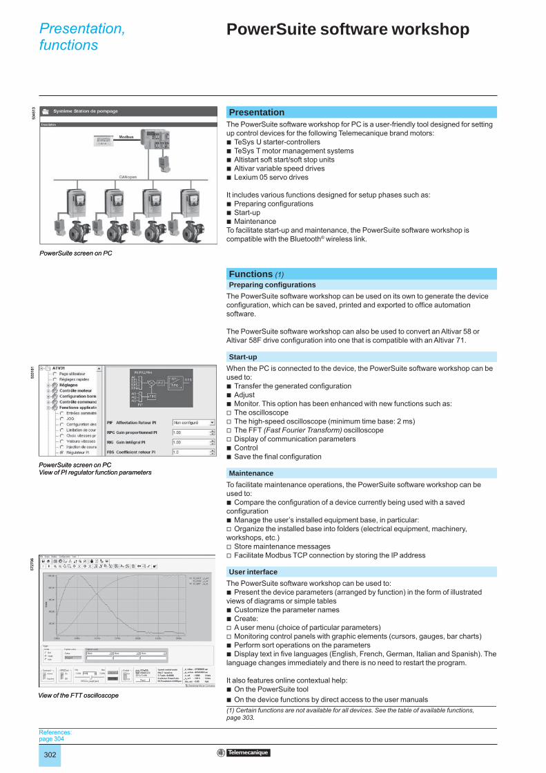
PresentationThe PowerSuite software workshop for PC is a user-friendly tool designed for setting up control devices for the following Telemecanique brand motors:
TeSys U starter-controllersTeSys T motor management systemsAltistart soft start/soft stop unitsAltivar variable speed drivesLexium 05 servo drives
It includes various functions designed for setup phases such as:Preparing confi gurationsStart-upMaintenance
To facilitate start-up and maintenance, the PowerSuite software workshop is compatible with the Bluetooth® wireless link.
Functions (1) Preparing confi gurations
The PowerSuite software workshop can be used on its own to generate the device confi guration, which can be saved, printed and exported to offi ce automation software.
The PowerSuite software workshop can also be used to convert an Altivar 58 or Altivar 58F drive confi guration into one that is compatible with an Altivar 71.
Start-upWhen the PC is connected to the device, the PowerSuite software workshop can be used to:
Transfer the generated confi gurationAdjustMonitor. This option has been enhanced with new functions such as:The oscilloscopeThe high-speed oscilloscope (minimum time base: 2 ms)The FFT (Fast Fourier Transform) oscilloscopeDisplay of communication parametersControlSave the fi nal confi guration
MaintenanceTo facilitate maintenance operations, the PowerSuite software workshop can be used to:
Compare the confi guration of a device currently being used with a saved confi guration
Manage the user’s installed equipment base, in particular:Organize the installed base into folders (electrical equipment, machinery,
workshops, etc.)Store maintenance messagesFacilitate Modbus TCP connection by storing the IP address
User interfaceThe PowerSuite software workshop can be used to:
Present the device parameters (arranged by function) in the form of illustrated views of diagrams or simple tables
Customize the parameter namesCreate:A user menu (choice of particular parameters)Monitoring control panels with graphic elements (cursors, gauges, bar charts)Perform sort operations on the parametersDisplay text in fi ve languages (English, French, German, Italian and Spanish). The
language changes immediately and there is no need to restart the program.
It also features online contextual help:On the PowerSuite toolOn the device functions by direct access to the user manuals
(1) Certain functions are not available for all devices. See the table of available functions, page 303.
bbbbb
bbb
bbbvvvvbb
b
bv
vv
b
bbvvbb
bb
5345
13
PowerSuite screen on PC
5345
13
PowerSuite screen on PC
5331
81
PowerSuite screen on PCView of PI regulator function parameters
5331
81
PowerSuite screen on PCView of PI regulator function parameters
5727
06
View of the FTT oscilloscope
5727
06
View of the FTT oscilloscope
References:page 304References:page 304References:page 304References:page 304
PowerSuite software workshop 3

303
Functions (continued) 3
Functions available for the PowerSuite software workshopFunctions not listed in the table are available for all devices.Function available with devices Controller Starter-
controllerSoft start/soft stop unit
Drives Servo drive
TeSys T TeSys U ATS 48 ATV 11 ATV 31 ATV 61 ATV 71 LXM 05MonitoringOscilloscopeHigh-speed oscilloscopeFFT oscilloscopeDisplay of communication parametersControlCustomization of parameter namesCreation of a user menuCreation of monitoring control panelsSort operation on parametersCustom logic editor
Functions available Functions not available
Connections (1)Modbus serial link
The PowerSuite software workshop can be connected directly to the device terminal port or Modbus network port via the serial port on the PC.
Two types of connection are possible:With a single device (point-to-point connection), use a VW3 A8 106 PC serial port
connection kit.With a number of devices (multidrop connection), use the XGS Z24 interface.
b
b
Modbus TCP communication networkThe PowerSuite software workshop can be connected to a Modbus TCP network.In this case, the devices can be accessed:
Using a VW3 A3 310 communication card for the Altivar 61and 71 drivesUsing a TSX ETG 100 Modbus TCP/Modbus gateway
bb
Bluetooth® wireless linkThe PowerSuite software workshop can communicate via a Bluetooth® radio link if the device is equipped with a Bluetooth® Modbus VW3 A8 114. The adapter plugs into the device connector terminal port or Modbus network port and has a range of 10 m (class 2).
If the PC does not feature Bluetooth® technology, use theVW3 A8 115 USB - Bluetooth® adapter.
Remote maintenanceA simple Modbus TCP connection is all that is required for the PowerSuite software workshop to support remote monitoring and diagnostics.When devices are not connected to the Modbus TCP network, or it is not directly accessible, various remote transmission solutions may be used instead (modem, teleprocessing gateway, etc.). Please consult your Regional Sales Offi ce.
(1) Please refer to the compatibility table on page 305.(2) Please refer to our specialist "Automation platform Modicon Premium and Unity - PL7
software" and "Automation platform Modicon TSX Micro - PL7 software" catalogues.
RS 232RS 485
5368
45
Modbus multidrop connection
Modbus serial link
ATV 31 or Lexium 05
ATV 61 ATV 71 TeSys U
PowerSuite
ATS 48
XGS Z24RS 232RS 485
5368
45
Modbus multidrop connection
Modbus serial link
ATV 31 or Lexium 05
ATV 61 ATV 71 TeSys U
PowerSuite
ATS 48
XGS Z24
5368
46
Modbus TCP connection
Bridge
PLC (2)
Modbus TCP network
ATV 31 or Lexium 05
ATS 48 ATV 61 ATV 71
Modbusserial link
PowerSuite
5368
46
Modbus TCP connection
Bridge
PLC (2)
Modbus TCP network
ATV 31 or Lexium 05
ATS 48 ATV 61 ATV 71
Modbusserial link
PowerSuite
Presentation:page 302
References:page 304
Presentation:page 302
References:page 304
Presentation:page 302
References:page 304
Presentation:page 302
References:page 304
PowerSuite software workshop 3
304
References 3
PowerSuite software workshopDescription Composition Reference Weight
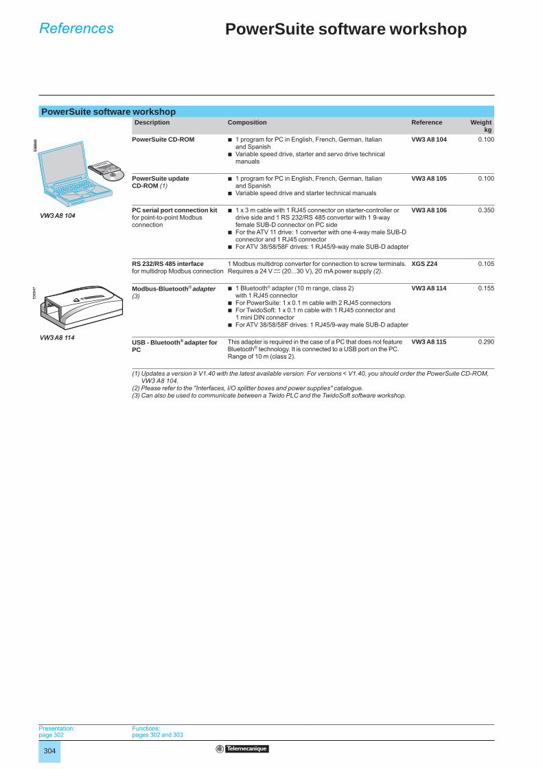
kgPowerSuite CD-ROM 1 program for PC in English, French, German, Italian
and Spanish Variable speed drive, starter and servo drive technical manuals
b
b
VW3 A8 104 0.100
PowerSuite update CD-ROM (1)
1 program for PC in English, French, German, Italian and Spanish Variable speed drive and starter technical manuals
b
b
VW3 A8 105 0.100
PC serial port connection kitfor point-to-point Modbus connection
1 x 3 m cable with 1 RJ45 connector on starter-controller or drive side and 1 RS 232/RS 485 converter with 1 9-way female SUB-D connector on PC sideFor the ATV 11 drive: 1 converter with one 4-way male SUB-D connector and 1 RJ45 connectorFor ATV 38/58/58F drives: 1 RJ45/9-way male SUB-D adapter
b
b
b
VW3 A8 106 0.350
RS 232/RS 485 interfacefor multidrop Modbus connection
1 Modbus multidrop converter for connection to screw terminals. Requires a 24 V c (20...30 V), 20 mA power supply (2).
XGS Z24 0.105
Modbus-Bluetooth® adapter (3)
1 Bluetooth® adapter (10 m range, class 2) with 1 RJ45 connectorFor PowerSuite: 1 x 0.1 m cable with 2 RJ45 connectorsFor TwidoSoft: 1 x 0.1 m cable with 1 RJ45 connector and 1 mini DIN connectorFor ATV 38/58/58F drives: 1 RJ45/9-way male SUB-D adapter
b
bb
b
VW3 A8 114 0.155
USB - Bluetooth® adapter for PC
This adapter is required in the case of a PC that does not featureBluetooth® technology. It is connected to a USB port on the PC.Range of 10 m (class 2).
VW3 A8 115 0.290
(1) Updates a version u V1.40 with the latest available version. For versions < V1.40, you should order the PowerSuite CD-ROM, VW3 A8 104.
(2) Please refer to the "Interfaces, I/O splitter boxes and power supplies" catalogue.(3) Can also be used to communicate between a Twido PLC and the TwidoSoft software workshop.
VW3 A8 104
5368
48
VW3 A8 104
5368
48
VW3 A8 114
5368
47
VW3 A8 114
5368
47
Presentation:page 302
Functions:pages 302 and 303
Presentation:page 302
Functions:pages 302 and 303
Presentation:page 302
Functions:pages 302 and 303
Presentation:page 302
Functions:pages 302 and 303
PowerSuite software workshop 3

305
Compatibility 3
Compatibility of PowerSuite software workshop with the following devices (1)Connection Controller Starter-
controllerSoft start/soft stop unit
Drives Servo drives
TeSys T TeSys U (2) ATS 48 ATV 11 ATV 31 ATV 61 ATV 71 LXM 05A LXM 05B LXM 05CModbus V2.5 V1.40 V1.30 V1.40 V2.0 V2.3 V2.2 V2.2 V2.4 V2.5Modbus TCP (device equipped with Modbus TCP card)
V2.3 V2.2
Modbus TCP via Modbus TCP/Modbus gateway
V1.50 V2.0 V2.3 V2.2 V2.2 V2.4 V2.5
Bluetooth® V2.2 V2.2 V2.3 V2.2 V2.2 V2.4 V2.5 Compatible software versions Incompatible software versions
Hardware and software environmentsThe PowerSuite software workshop can operate in the following PC environments and confi gurations:
Microsoft Windows® XP SP1, SP2,Pentium III, 800 MHz, hard disk with 300 MB available, 128 MB RAMSVGA or higher defi nition monitor
bbb
(1) Minimum software version(2) TeSys U starter-controller without communication module or with Modbus LUL C031, C032 or C033 communication module
Presentation:page 302
Functions:pages 302 and 303
References:page 304
Presentation:page 302
Functions:pages 302 and 303
References:page 304
Presentation:page 302
Functions:pages 302 and 303
References:page 304
Presentation:page 302
Functions:pages 302 and 303
References:page 304
PowerSuite software workshop 3
306
Presentation Starters, drivesand communication3 Modbus TCP networkTransparent Ready concept
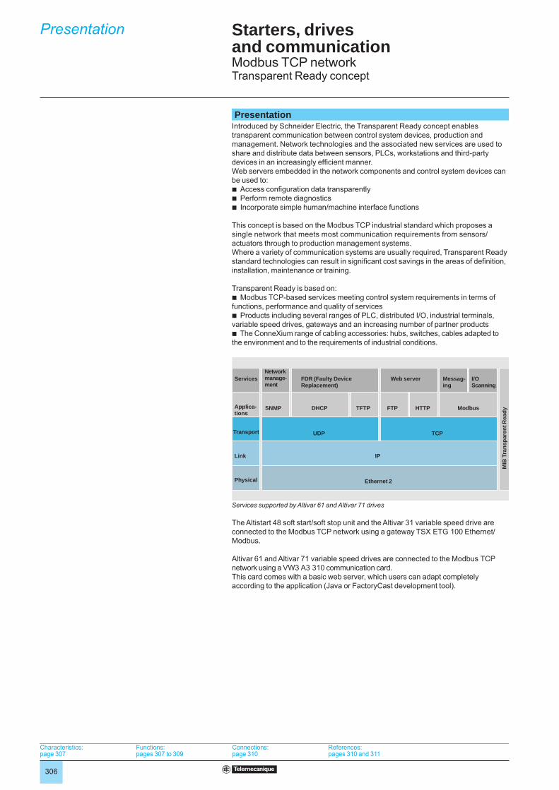
PresentationIntroduced by Schneider Electric, the Transparent Ready concept enables transparent communication between control system devices, production and management. Network technologies and the associated new services are used to share and distribute data between sensors, PLCs, workstations and third-party devices in an increasingly effi cient manner. Web servers embedded in the network components and control system devices can be used to: b Access confi guration data transparentlyb Perform remote diagnosticsb Incorporate simple human/machine interface functions
This concept is based on the Modbus TCP industrial standard which proposes a single network that meets most communication requirements from sensors/actuators through to production management systems.Where a variety of communication systems are usually required, Transparent Ready standard technologies can result in signifi cant cost savings in the areas of defi nition, installation, maintenance or training.
Transparent Ready is based on:b Modbus TCP-based services meeting control system requirements in terms of functions, performance and quality of servicesb Products including several ranges of PLC, distributed I/O, industrial terminals, variable speed drives, gateways and an increasing number of partner productsb The ConneXium range of cabling accessories: hubs, switches, cables adapted to the environment and to the requirements of industrial conditions.
Services
Applica- tions
Transport
Link
Physical
Network manage-ment
FDR (Faulty Device Replacement)
Web server Messag-ing
I/OScanning
SNMP DHCP TFTP FTP HTTP Modbus
UDP TCP
IP
Ethernet 2
MIB
Tra
nspa
rent
Rea
dyServices supported by Altivar 61 and Altivar 71 drives
The Altistart 48 soft start/soft stop unit and the Altivar 31 variable speed drive are connected to the Modbus TCP network using a gateway TSX ETG 100 Ethernet/Modbus.
Altivar 61 and Altivar 71 variable speed drives are connected to the Modbus TCP network using a VW3 A3 310 communication card.This card comes with a basic web server, which users can adapt completely according to the application (Java or FactoryCast development tool).
Characteristics:page 307
Functions:pages 307 to 309
Connections:page 310
References:pages 310 and 311
Characteristics:page 307
Functions:pages 307 to 309
Connections:page 310
References:pages 310 and 311
Characteristics:page 307
Functions:pages 307 to 309
Connections:page 310
References:pages 310 and 311
Characteristics:page 307
Functions:pages 307 to 309
Connections:page 310
References:pages 310 and 311
307
Characteristics,functions
CharacteristicsStructure Topology Industrial local area network conforming to ANSI/IEEE 802.3 (4th edition 1993-07-08)
Star networkTransmission mode Manchester baseband. Half-duplex or full-duplexData rate 10/100 Mbps with automatic recognitionMedium STP double shielded twisted pair, impedance 100 W ± 15 W for 10 BASE-T or category 5
Ethernet cable, conforming to standard TIA/EIA-568ALength of network 100 m maximum between hub or switch and a station
Type of device ATS 48, ATV 31 ATV 61, ATV 71Type of interface TSX ETG 100 VW3 A3 310
Universal services SNMP HTTP, BOOTP, DHCP, FTP, TFTP, SNMPTransparent Ready services Modbus Messaging Modbus messaging, IO Scanning, FDR
Universal servicesHTTP
HTTP, “Hypertext Transfer Protocol” (RFC 1945), is a protocol used to transmit web pages between a server and a browser. HTTP has been used on the Web since 1990.
Web servers embedded in control system devices are at the heart of the Transparent Ready concept and provide easy access to devices anywhere in the world using a standard web browser such as Internet Explorer or Netscape Navigator.
BOOTP/DHCPBOOTP/DHCP (RFC 1531) is used to supply (client) devices automatically with IP addresses and parameters. This avoids having to manage the addresses of each device individually by transferring their management to a server.BOOTP identifi es the client device by its Ethernet MAC address. This address is unique to each device and must be entered in the server each time the device is changed.DHCP “Dynamic Host Confi guration Protocol” identifi es the client device by a name in plain language (“Device Name”) which is maintained throughout the application: e.g. “Conveyor 23”.
Altivar 61 and Altivar 71 drives can be given a name (“Device Name”) by the terminal or the PowerSuite software workshop.The FDR (“Faulty Device Replacement”) service uses the standard DHCP and TFTP protocols.
FTP/TFTPFTP, “File Transfer Protocol” (RFCs 959, 2228 and 2640), and TFTP, “Trivial File Transfer Protocol” (RFC 1123), are used to exchange fi les with devices.
Transparent Ready devices implement FTP for downloading fi rmware or custom web pages.The FDR (“Faulty Device Replacement”) service uses the standard DHCP and TFTP protocols.
SNMP The Internet community has developed the SNMP standard, “Simple Network Management Protocol” (RFCs 1155, 1156 and 1157), to support the management of the various network components by means of a single system. The network management system can exchange data with SNMP agent devices. This function allows the manager to view the status of the network and devices, to modify their confi guration and to return alarms in the event of a fault.
Transparent Ready devices are compatible with SNMP and can be integrated naturally into a network administered via SNMP.
Presentation:page 306
Connections:page 310
References:pages 310 and 311
Presentation:page 306
Connections:page 310
References:pages 310 and 311
Presentation:page 306
Connections:page 310
References:pages 310 and 311
Presentation:page 306
Connections:page 310
References:pages 310 and 311
Starters, drivesand communication3 Modbus TCP networkTransparent Ready concept
308
Functions (continued)
Transparent Ready servicesModbus communication standard
Modbus, the industry communication standard since 1979, has been ported to Ethernet TCP/IP, the backbone of the Internet revolution, to create Modbus TCP, a totally open protocol on Ethernet. There is no need for any proprietary component, nor the purchase of a licence in order to develop a connection to Modbus TCP.This protocol can easily be ported to any device supporting a standard TCP/IP communication stack. The specifi cations can be obtained free of charge from the website: www.modbus.org.
Modbus TCP, simple and openThe Modbus application layer is very simple and universally known. Thousands of manufacturers are already implementing this protocol. Many have already developed a Modbus TCP connection and numerous products are currently available.The simplicity of Modbus TCP enables any small fi eld device, such as an I/O module, to communicate on Ethernet without the need for a powerful microprocessor or a large amount of internal memory.
Modbus TCP, high performanceThanks to the simplicity of its protocol and the fast Ethernet throughput data rate of 100 Mbps, Modbus TCP achieves excellent performance. This means that this type of network can be used in realtime applications such as I/O Scanning.
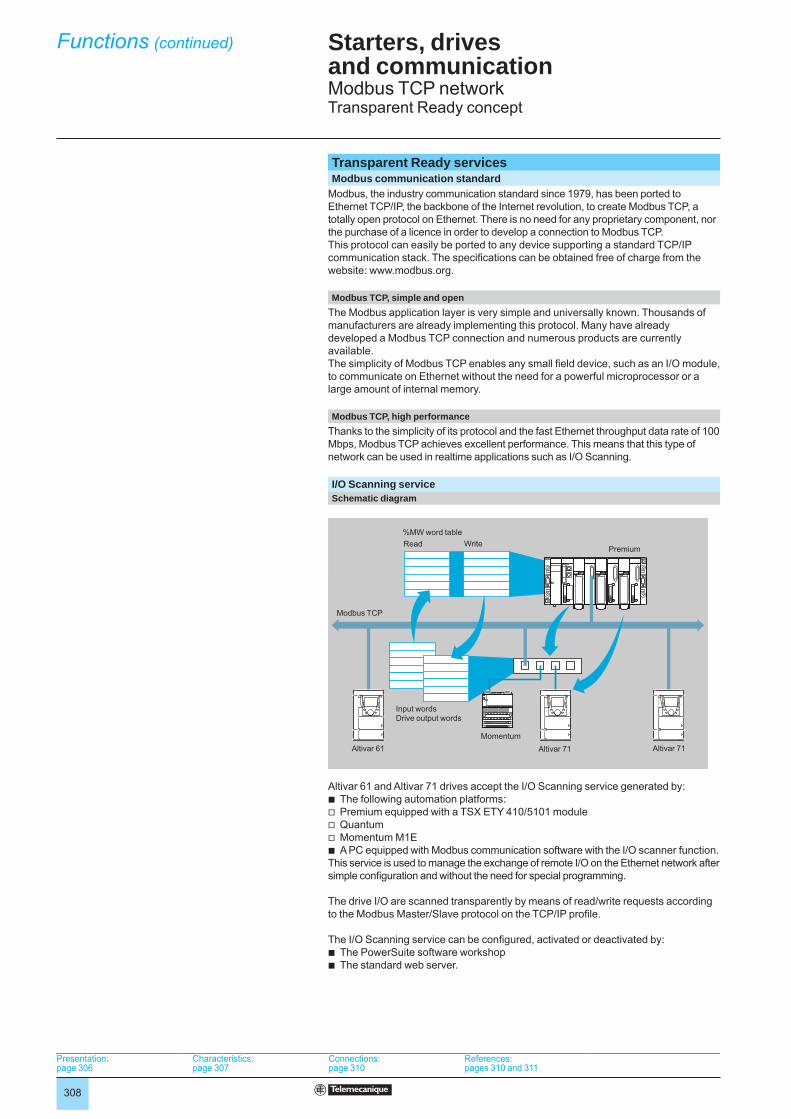
I/O Scanning serviceSchematic diagram
Altivar 61 and Altivar 71 drives accept the I/O Scanning service generated by:b The following automation platforms:v Premium equipped with a TSX ETY 410/5101 modulev Quantumv Momentum M1Eb A PC equipped with Modbus communication software with the I/O scanner function.This service is used to manage the exchange of remote I/O on the Ethernet network after simple confi guration and without the need for special programming.
The drive I/O are scanned transparently by means of read/write requests according to the Modbus Master/Slave protocol on the TCP/IP profi le.
The I/O Scanning service can be confi gured, activated or deactivated by:b The PowerSuite software workshopb The standard web server.
Read Write%MW word table
Premium
Modbus TCP
Input wordsDrive output words
Altivar 61 Altivar 71 Altivar 71Momentum
Read Write%MW word table
Premium
Modbus TCP
Input wordsDrive output words
Altivar 61 Altivar 71 Altivar 71Momentum
Presentation:page 306
Characteristics:page 307
Connections:page 310
References:pages 310 and 311
Presentation:page 306
Characteristics:page 307
Connections:page 310
References:pages 310 and 311
Presentation:page 306
Characteristics:page 307
Connections:page 310
References:pages 310 and 311
Presentation:page 306
Characteristics:page 307
Connections:page 310
References:pages 310 and 311
Starters, drivesand communication3 Modbus TCP networkTransparent Ready concept
309
Transparent Ready services (continued)Faulty Device Replacement (FDR) service
The FDR service uses standard DHCP and TFTP technologies with the aim of simplifying the maintenance of Ethernet devices.It is used to replace a faulty device with a new product, ensuring its detection, reconfi guration and automatic restarting by the system, without the need for any tricky manual intervention.
The main steps are:b A device using the FDR service becomes faultyb A similar device is taken out of the maintenance reserve base, preconfi gured with the “Device_name” of the faulty device, then reinstalled on the network.b The FDR server (which can be a Quantum or Premium PLC Ethernet module) detects the new arrival, confi gures it with its IP address and transfers all its confi guration parameters to it.b The substituted device checks that the parameters are fully compatible with its own characteristics, then switches to operational mode.
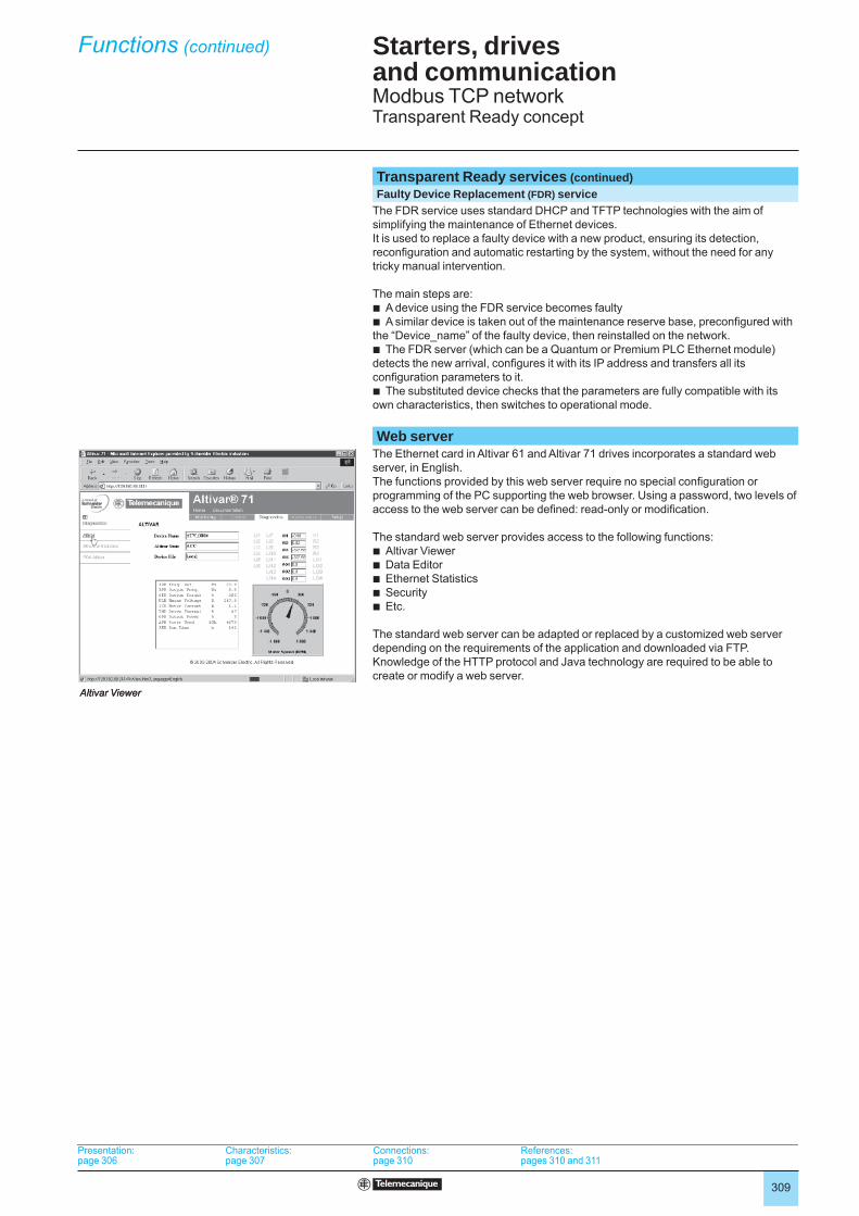
Web serverThe Ethernet card in Altivar 61 and Altivar 71 drives incorporates a standard web server, in English.The functions provided by this web server require no special confi guration or programming of the PC supporting the web browser. Using a password, two levels of access to the web server can be defi ned: read-only or modifi cation.
The standard web server provides access to the following functions:b Altivar Viewerb Data Editorb Ethernet Statisticsb Securityb Etc.
The standard web server can be adapted or replaced by a customized web server depending on the requirements of the application and downloaded via FTP. Knowledge of the HTTP protocol and Java technology are required to be able to create or modify a web server.
Altivar ViewerAltivar Viewer
Presentation:page 306
Characteristics:page 307
Connections:page 310
References:pages 310 and 311
Presentation:page 306
Characteristics:page 307
Connections:page 310
References:pages 310 and 311
Presentation:page 306
Characteristics:page 307
Connections:page 310
References:pages 310 and 311
Presentation:page 306
Characteristics:page 307
Connections:page 310
References:pages 310 and 311
Starters, drivesand communication3 Modbus TCP networkTransparent Ready concept
Functions (continued)
310
Connections,references
Connections
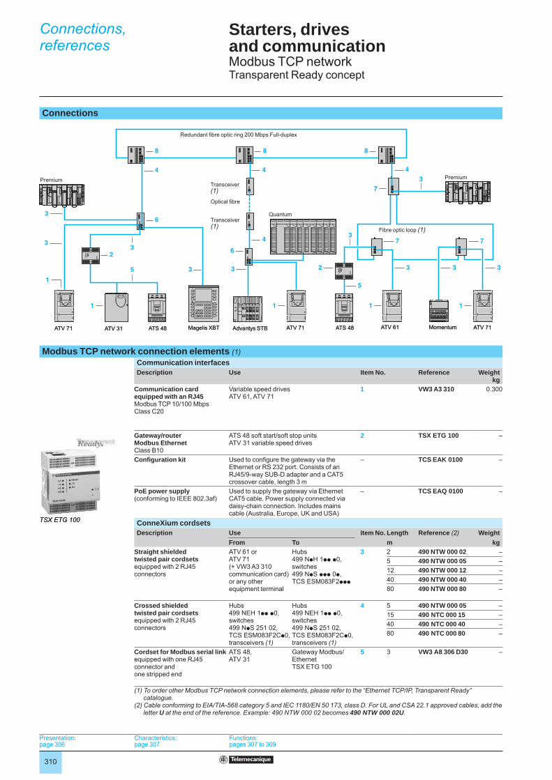
Modbus TCP network connection elements (1)Communication interfacesDescription Use Item No. Reference Weight
kgCommunication card equipped with an RJ45Modbus TCP 10/100 Mbps Class C20
Variable speed drivesATV 61, ATV 71
1 VW3 A3 310 0.300
Gateway/routerModbus EthernetClass B10
ATS 48 soft start/soft stop unitsATV 31 variable speed drives
2 TSX ETG 100 –
Confi guration kit Used to confi gure the gateway via the Ethernet or RS 232 port. Consists of an RJ45/9-way SUB-D adapter and a CAT5 crossover cable, length 3 m
– TCS EAK 0100 –
PoE power supply(conforming to IEEE 802.3af)
Used to supply the gateway via Ethernet CAT5 cable. Power supply connected via daisy-chain connection. Includes mains cable (Australia, Europe, UK and USA)
– TCS EAQ 0100 –
ConneXium cordsetsDescription Use Item No. Length Reference (2) Weight
From To m kgStraight shielded twisted pair cordsetsequipped with 2 RJ45 connectors
ATV 61 orATV 71 (+ VW3 A3 310 communication card) or any other equipment terminal
Hubs 499 NpH 1pp p0, switches 499 NpS ppp 0p,TCS ESM083F2ppp
3 2 490 NTW 000 02 –5 490 NTW 000 05 –12 490 NTW 000 12 –40 490 NTW 000 40 –80 490 NTW 000 80 –
Crossed shielded twisted pair cordsets equipped with 2 RJ45 connectors
Hubs 499 NEH 1pp p0, switches499 NpS 251 02, TCS ESM083F2Cp0, transceivers (1)
Hubs 499 NEH 1pp p0, switches 499 NpS 251 02,TCS ESM083F2Cp0, transceivers (1)
4 5 490 NTW 000 05 –15 490 NTC 000 15 –40 490 NTC 000 40 –80 490 NTC 000 80 –
Cordset for Modbus serial linkequipped with one RJ45 connector and one stripped end
ATS 48, ATV 31
Gateway Modbus/EthernetTSX ETG 100
5 3 VW3 A8 306 D30 –
(1) To order other Modbus TCP network connection elements, please refer to the “Ethernet TCP/IP, Transparent Ready” catalogue.
(2) Cable conforming to EIA/TIA-568 category 5 and IEC 1180/EN 50 173, class D. For UL and CSA 22.1 approved cables, add the letter U at the end of the reference. Example: 490 NTW 000 02 becomes 490 NTW 000 02U.
3
3
3 3
6
7
1
3
2 35
3
8
4
4
4
2
6
8 8
1
1 1 1
3
4
33
7 7
5
ATV 71 Magelis XBT ATV 71 ATS 48
Transceiver(1)
Redundant fi bre optic ring 200 Mbps Full-duplex
Transceiver (1)
Quantum
Premium
Fibre optic loop (1)
Optical fi bre
ATV 71ATV 61ATV 31 ATS 48 Advantys STB Momentum
Premium 3
3
3 3
6
7
1
3
2 35
3
8
4
4
4
2
6
8 8
1
1 1 1
3
4
33
7 7
5
ATV 71 Magelis XBT ATV 71 ATS 48
Transceiver(1)
Redundant fi bre optic ring 200 Mbps Full-duplex
Transceiver (1)
Quantum
Premium
Fibre optic loop (1)
Optical fi bre
ATV 71ATV 61ATV 31 ATS 48 Advantys STB Momentum
Premium
TSX ETG 100TSX ETG 100
Presentation:page 306
Characteristics:page 307
Functions:pages 307 to 309
Presentation:page 306
Characteristics:page 307
Functions:pages 307 to 309
Presentation:page 306
Characteristics:page 307
Functions:pages 307 to 309
Presentation:page 306
Characteristics:page 307
Functions:pages 307 to 309
Starters, drivesand communication3 Modbus TCP networkTransparent Ready concept
311
References (continued)
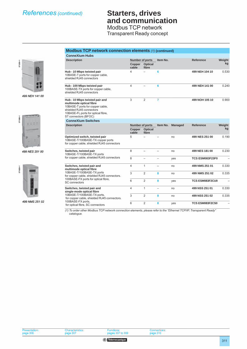
Modbus TCP network connection elements (1) (continued)ConneXium HubsDescription Number of ports Item No. Reference Weight
kgCopper cable
Optical fi bre
Hub - 10 Mbps twisted pair10BASE-T ports for copper cable, shielded RJ45 connectors
4 – 6 499 NEH 104 10 0.530
Hub - 100 Mbps twisted pair100BASE-TX ports for copper cable, shielded RJ45 connectors
4 – 6 499 NEH 141 00 0.240
Hub - 10 Mbps twisted pair and multimode optical fi bre10BASE-T ports for copper cable, shielded RJ45 connectors10BASE-FL ports for optical fi bre, ST connectors (BFOC)
3 2 7 499 NOH 105 10 0.900
ConneXium SwitchesDescription Number of ports Item No. Managed Reference Weight
kgCopper cable
Optical fi bre
Optimized switch, twisted pair10BASE-T/100BASE-TX copper ports for copper cable, shielded RJ45 connectors
5 – – no 499 NES 251 00 0.190
Switches, twisted pair10BASE-T/100BASE-TX ports for copper cable, shielded RJ45 connectors
8 – – no 499 NES 181 00 0.230
8 – – yes TCS ESM083F23F0 –
Switches, twisted pair and multimode optical fi bre10BASE-T/100BASE-TX ports for copper cable, shielded RJ45 connectors.100BASE-FX ports for optical fi bre, SC connectors
4 1 – no 499 NMS 251 01 0.330
3 2 8 no 499 NMS 251 02 0.335
6 2 8 yes TCS ESM083F2CU0 –
Switches, twisted pair and single-mode optical fi bre10BASE-T/100BASE-TX ports, for copper cable, shielded RJ45 connectors.100BASE-FX ports, for optical fi bre, SC connectors
4 1 – no 499 NSS 251 01 0.330
3 2 8 no 499 NSS 251 02 0.335
6 2 8 yes TCS ESM083F2CS0 –
(1) To order other Modbus TCP network connection elements, please refer to the “Ethernet TCP/IP, Transparent Ready” catalogue.
5712
00~1
499 NEH 141 00
5712
00~1
499 NEH 141 00
5713
85~1
499 NES 251 00
5713
85~1
499 NES 251 00
5718
29~1
499 NMS 251 02
5718
29~1
499 NMS 251 02
Presentation:page 306
Characteristics:page 307
Functions:pages 307 to 309
Connections:page 310
Presentation:page 306
Characteristics:page 307
Functions:pages 307 to 309
Connections:page 310
Presentation:page 306
Characteristics:page 307
Functions:pages 307 to 309
Connections:page 310
Presentation:page 306
Characteristics:page 307
Functions:pages 307 to 309
Connections:page 310
Starters, drivesand communication3 Modbus TCP networkTransparent Ready concept
312
Starters, drives and communication3 Communication via Fipio bus
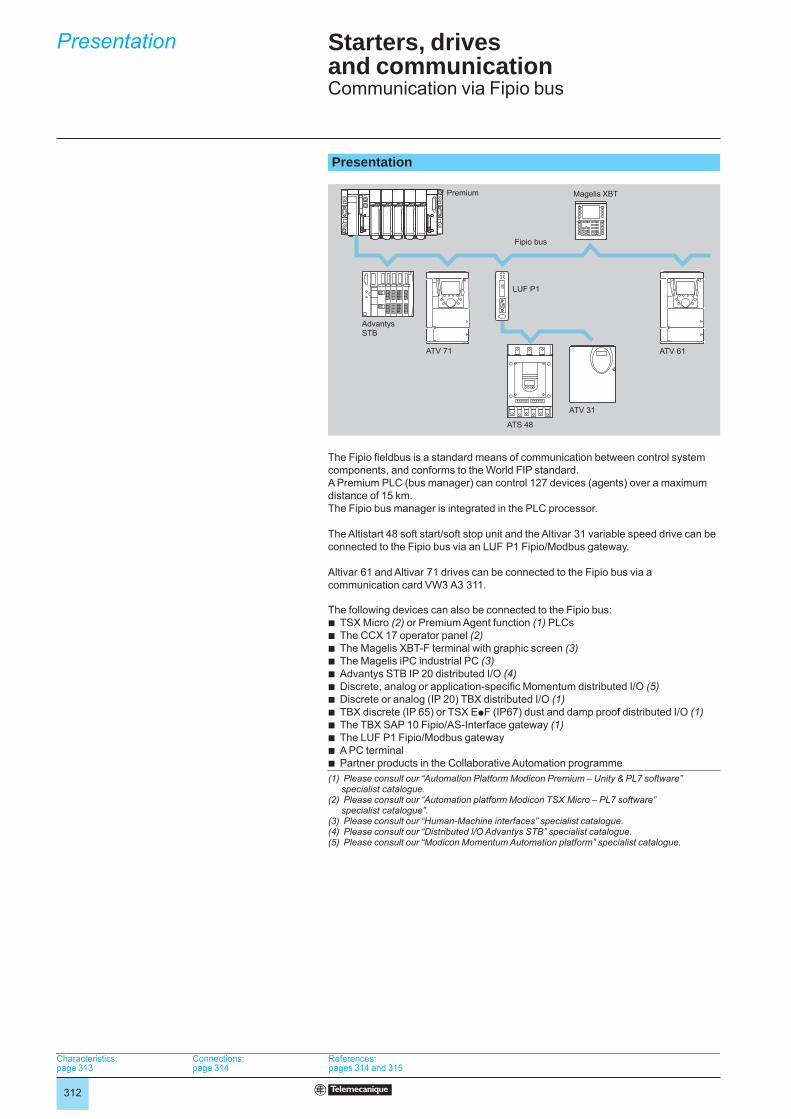
Presentation
The Fipio fi eldbus is a standard means of communication between control system components, and conforms to the World FIP standard.A Premium PLC (bus manager) can control 127 devices (agents) over a maximum distance of 15 km.The Fipio bus manager is integrated in the PLC processor.
The Altistart 48 soft start/soft stop unit and the Altivar 31 variable speed drive can be connected to the Fipio bus via an LUF P1 Fipio/Modbus gateway.
Altivar 61 and Altivar 71 drives can be connected to the Fipio bus via a communication card VW3 A3 311.
The following devices can also be connected to the Fipio bus:b TSX Micro (2) or Premium Agent function (1) PLCsb The CCX 17 operator panel (2)b The Magelis XBT-F terminal with graphic screen (3) b The Magelis iPC industrial PC (3)b Advantys STB IP 20 distributed I/O (4)b Discrete, analog or application-specifi c Momentum distributed I/O (5)b Discrete or analog (IP 20) TBX distributed I/O (1)b TBX discrete (IP 65) or TSX EpF (IP67) dust and damp proof distributed I/O (1)b The TBX SAP 10 Fipio/AS-Interface gateway (1) b The LUF P1 Fipio/Modbus gatewayb A PC terminalb Partner products in the Collaborative Automation programme(1) Please consult our “Automation Platform Modicon Premium – Unity & PL7 software”
specialist catalogue.(2) Please consult our “Automation platform Modicon TSX Micro – PL7 software”
specialist catalogue”.(3) Please consult our “Human-Machine interfaces” specialist catalogue.(4) Please consult our “Distributed I/O Advantys STB” specialist catalogue.(5) Please consult our “Modicon Momentum Automation platform” specialist catalogue.
Fipio bus
Premium
AdvantysSTB
ATV 71 ATV 61
ATS 48
LUF P1
ATV 31
Magelis XBT
Fipio bus
Premium
AdvantysSTB
ATV 71 ATV 61
ATS 48
LUF P1
ATV 31
Magelis XBT
Characteristics: page 313
Connections:page 314
References: pages 314 and 315
Characteristics: page 313
Connections:page 314
References: pages 314 and 315
Characteristics: page 313
Connections:page 314
References: pages 314 and 315
Characteristics: page 313
Connections:page 314
References: pages 314 and 315
Presentation

313
Starters, drives and communication3 Communication via Fipio bus
CharacteristicsStructure Topology Industrial bus conforming to the World FIP standard
Subscribers linked via daisy-chain or tap junctions
Access method Producer/consumer principleBus management by a fi xed arbitrator (bus manager)
Transmission mode Baseband physical layer on shielded twisted pair, according to standard NF C 46-604
Data rate 1 Mbps
Medium Shielded twisted pair 150 ΩOptical fi bre 62.5/125 with the use of electrical/fi bre optic repeaters
Number of subscribers 32 maximum per segment1 manager + 127 agents maximum over all segmentsThe number of Fipio agents is limited by the memory capacity of Premium processors (62 Altivar drives maximum) (1)
Number of segments Unlimited in tree or star architecturesLimited to 5 cascaded segmentsThe link between 2 subscribers may cross 4 electrical or electrical/fi bre optic repeaters maximum
Length of bus 15,000 m maximum1,000 m maximum without repeater for an electrical segment5,000 m maximum for 5 electrical segments3,000 m maximum for 1 fi bre optic segment
Type of device ATS 48, ATV 31 ATV 61, ATV 71Type of interface LUF P1 VW3 A3 311
Profi le FED C 32P FED C 32
Control and adjustment 26 confi gurable words 8 confi gurable words (communication scanner)Monitoring 26 confi gurable words 8 confi gurable words (communication scanner)Confi guration and adjustment 1 indexed word
Read/write access to all functions by the PLC application program(1) Please consult our “Automation Platform Modicon Premium – Unity & PL7 software”
specialist catalogue.
Presentation: page 312
Connections:page 314
References: pages 314 and 315
Presentation: page 312
Connections:page 314
References: pages 314 and 315
Presentation: page 312
Connections:page 314
References: pages 314 and 315
Presentation: page 312
Connections:page 314
References: pages 314 and 315
Characteristics
314
Starters, drives and communication3 Communication via Fipio bus
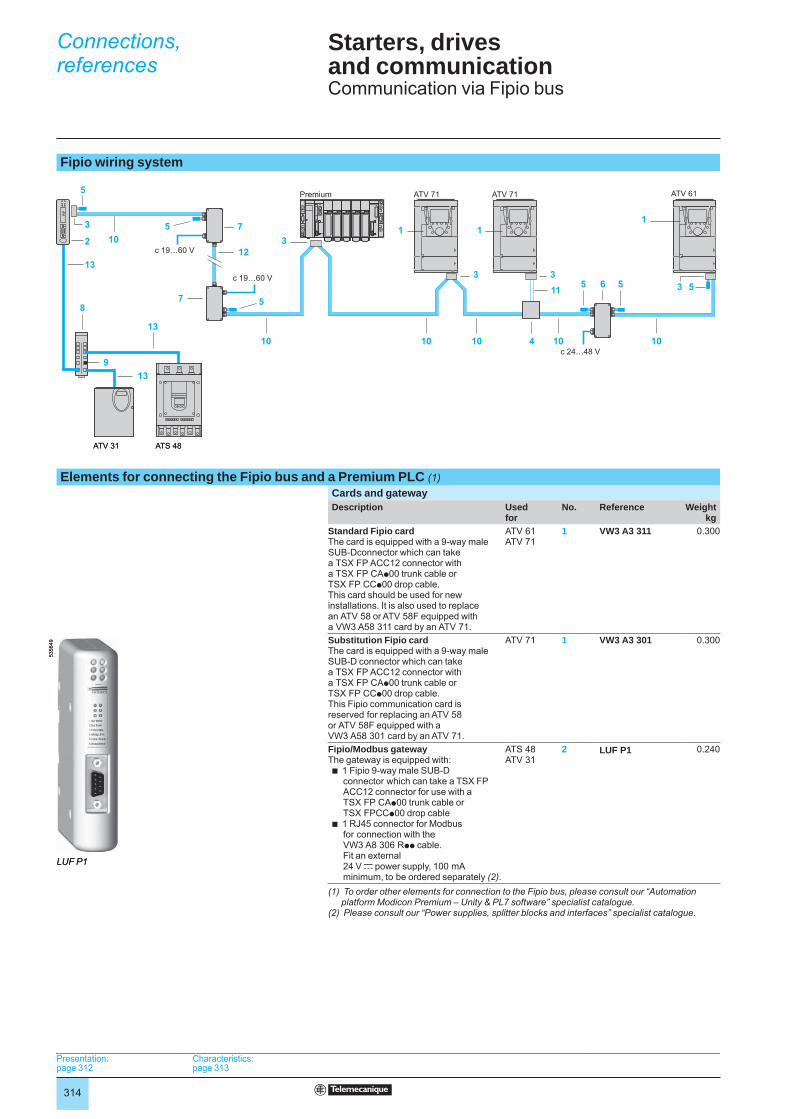
Fipio wiring system
Elements for connecting the Fipio bus and a Premium PLC (1)Cards and gatewayDescription Used
forNo. Reference Weight
kgStandard Fipio cardThe card is equipped with a 9-way maleSUB-Dconnector which can take a TSX FP ACC12 connector with a TSX FP CAp00 trunk cable or TSX FP CCp00 drop cable.This card should be used for new installations. It is also used to replace an ATV 58 or ATV 58F equipped with a VW3 A58 311 card by an ATV 71.
ATV 61 ATV 71
1 VW3 A3 311 0.300
Substitution Fipio cardThe card is equipped with a 9-way maleSUB-D connector which can take a TSX FP ACC12 connector with a TSX FP CAp00 trunk cable or TSX FP CCp00 drop cable.This Fipio communication card is reserved for replacing an ATV 58 or ATV 58F equipped with a VW3 A58 301 card by an ATV 71.
ATV 71 1 VW3 A3 301 0.300
Fipio/Modbus gatewayThe gateway is equipped with:b 1 Fipio 9-way male SUB-D
connector which can take a TSX FP ACC12 connector for use with a TSX FP CAp00 trunk cable or TSX FPCCp00 drop cable
b 1 RJ45 connector for Modbus for connection with the VW3 A8 306 Rpp cable.Fit an external24 V c power supply, 100 mA minimum, to be ordered separately (2).
ATS 48ATV 31
2 LUF P1 0.240
(1) To order other elements for connection to the Fipio bus, please consult our “Automation platform Modicon Premium – Unity & PL7 software” specialist catalogue.
(2) Please consult our “Power supplies, splitter blocks and interfaces” specialist catalogue.
4
5
5
5
33
3
535 5
13
8
6
10 101010
1312
11
9
7
7
13
10
103
21 1
c 19…60 V
c 19…60 V
c 24…48 V
1
ATV 61
ATS 48ATV 31
ATV 71ATV 71Premium
4
5
5
5
33
3
535 5
13
8
6
10 101010
1312
11
9
7
7
13
10
103
21 1
c 19…60 V
c 19…60 V
c 24…48 V
1
ATV 61
ATS 48ATV 31
ATV 71ATV 71Premium
LUF P1
5356
49
LUF P1
5356
49
Presentation: page 312
Characteristics: page 313
Presentation: page 312
Characteristics: page 313
Presentation: page 312
Characteristics: page 313
Presentation: page 312
Characteristics: page 313
Connections,references
315
Starters, drives and communication3 Communication via Fipio bus
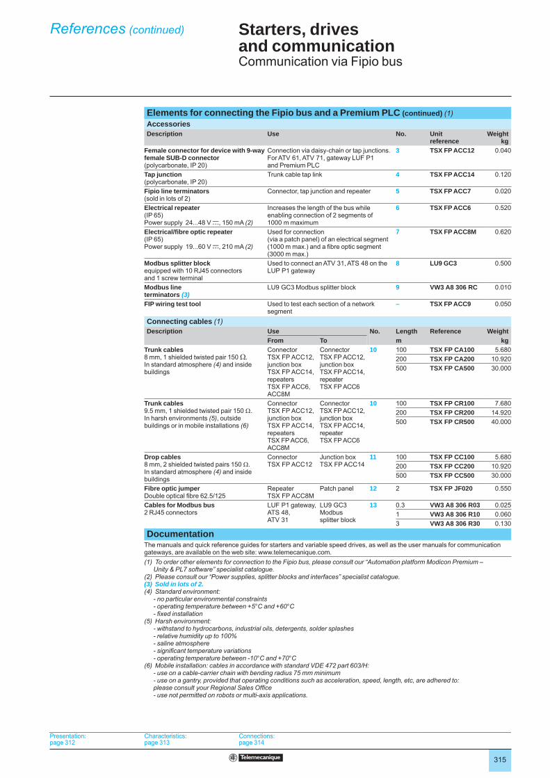
Elements for connecting the Fipio bus and a Premium PLC (continued) (1)AccessoriesDescription Use No. Unit
referenceWeight
kgFemale connector for device with 9-way female SUB-D connector(polycarbonate, IP 20)
Connection via daisy-chain or tap junctions. For ATV 61, ATV 71, gateway LUF P1 and Premium PLC
3 TSX FP ACC12 0.040
Tap junction(polycarbonate, IP 20)
Trunk cable tap link 4 TSX FP ACC14 0.120
Fipio line terminators(sold in lots of 2)
Connector, tap junction and repeater 5 TSX FP ACC7 0.020
Electrical repeater(IP 65)Power supply 24...48 V c, 150 mA (2)
Increases the length of the bus while enabling connection of 2 segments of 1000 m maximum
6 TSX FP ACC6 0.520
Electrical/fi bre optic repeater(IP 65)Power supply 19...60 V c, 210 mA (2)
Used for connection (via a patch panel) of an electrical segment (1000 m max.) and a fi bre optic segment (3000 m max.)
7 TSX FP ACC8M 0.620
Modbus splitter blockequipped with 10 RJ45 connectors and 1 screw terminal
Used to connect an ATV 31, ATS 48 on the LUP P1 gateway
8 LU9 GC3 0.500
Modbus lineterminators (3)
LU9 GC3 Modbus splitter block 9 VW3 A8 306 RC 0.010
FIP wiring test tool Used to test each section of a network segment
– TSX FP ACC9 0.050
Connecting cables (1)Description Use No. Length Reference Weight
From To m kgTrunk cables8 mm, 1 shielded twisted pair 150 Ω.In standard atmosphere (4) and inside buildings
Connector TSX FP ACC12,junction box TSX FP ACC14,repeaters TSX FP ACC6, ACC8M
Connector TSX FP ACC12,junction box TSX FP ACC14, repeater TSX FP ACC6
10 100 TSX FP CA100 5.680200 TSX FP CA200 10.920500 TSX FP CA500 30.000
Trunk cables9.5 mm, 1 shielded twisted pair 150 Ω. In harsh environments (5), outside buildings or in mobile installations (6)
Connector TSX FP ACC12,junction box TSX FP ACC14,repeaters TSX FP ACC6, ACC8M
Connector TSX FP ACC12,junction box TSX FP ACC14, repeater TSX FP ACC6
10 100 TSX FP CR100 7.680200 TSX FP CR200 14.920500 TSX FP CR500 40.000
Drop cables8 mm, 2 shielded twisted pairs 150 Ω.In standard atmosphere (4) and inside buildings
ConnectorTSX FP ACC12
Junction box TSX FP ACC14
11 100 TSX FP CC100 5.680200 TSX FP CC200 10.920500 TSX FP CC500 30.000
Fibre optic jumperDouble optical fi bre 62.5/125
Repeater TSX FP ACC8M
Patch panel 12 2 TSX FP JF020 0.550
Cables for Modbus bus2 RJ45 connectors
LUF P1 gateway,ATS 48,ATV 31
LU9 GC3 Modbus splitter block
13 0.3 VW3 A8 306 R03 0.0251 VW3 A8 306 R10 0.0603 VW3 A8 306 R30 0.130
DocumentationThe manuals and quick reference guides for starters and variable speed drives, as well as the user manuals for communication gateways, are available on the web site: www.telemecanique.com.(1) To order other elements for connection to the Fipio bus, please consult our “Automation platform Modicon Premium –
Unity & PL7 software” specialist catalogue.(2) Please consult our “Power supplies, splitter blocks and interfaces” specialist catalogue.(3) Sold in lots of 2.(4) Standard environment:
- no particular environmental constraints- operating temperature between +5°C and +60°C- fi xed installation
(5) Harsh environment: - withstand to hydrocarbons, industrial oils, detergents, solder splashes- relative humidity up to 100% - saline atmosphere- signifi cant temperature variations- operating temperature between -10°C and +70°C
(6) Mobile installation: cables in accordance with standard VDE 472 part 603/H:- use on a cable-carrier chain with bending radius 75 mm minimum - use on a gantry, provided that operating conditions such as acceleration, speed, length, etc, are adhered to: please consult your Regional Sales Offi ce- use not permitted on robots or multi-axis applications.
Presentation: page 312
Characteristics: page 313
Connections:page 314
Presentation: page 312
Characteristics: page 313
Connections:page 314
Presentation: page 312
Characteristics: page 313
Connections:page 314
Presentation: page 312
Characteristics: page 313
Connections:page 314
References (continued)
316
Starters, drives and communication 1 Communication via Modbus serial link
Presentation
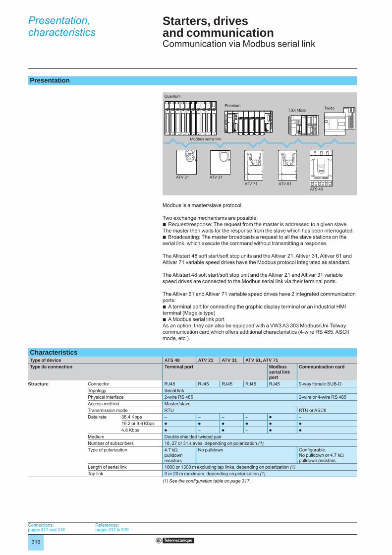
Modbus is a master/slave protocol.
Two exchange mechanisms are possible:Request/response: The request from the master is addressed to a given slave.
The master then waits for the response from the slave which has been interrogated.Broadcasting: The master broadcasts a request to all the slave stations on the
serial link, which execute the command without transmitting a response.
The Altistart 48 soft start/soft stop units and the Altivar 21, Altivar 31, Altivar 61 and Altivar 71 variable speed drives have the Modbus protocol integrated as standard.
The Altistart 48 soft start/soft stop unit and the Altivar 21 and Altivar 31 variable speed drives are connected to the Modbus serial link via their terminal ports. The Altivar 61 and Altivar 71 variable speed drives have 2 integrated communication ports:
A terminal port for connecting the graphic display terminal or an industrial HMI terminal (Magelis type)
A Modbus serial link portAs an option, they can also be equipped with a VW3 A3 303 Modbus/Uni-Telway communication card which offers additional characteristics (4-wire RS 485, ASCII mode, etc.).
b
b
b
b
CharacteristicsType of device ATS 48 ATV 21 ATV 31 ATV 61, ATV 71Type de connection Terminal port Modbus
serial link port
Communication card
Structure Connector RJ45 RJ45 RJ45 RJ45 RJ45 9-way female SUB-DTopology Serial linkPhysical interface 2-wire RS 485 2-wire or 4-wire RS 485Access method Master/slaveTransmission mode RTU RTU or ASCIIData rate 38.4 Kbps – – – – p –
19.2 or 9.6 Kbps p p p p p p
4.8 Kbps p – p – p p
Medium Double shielded twisted pairNumber of subscribers 18, 27 or 31 slaves, depending on polarization (1) Type of polarization 4.7 kΩ
pull down resistors
No pulldown Confi gurable.No pulldown or 4.7 kΩ pulldown resistors
Length of serial link 1000 or 1300 m excluding tap links, depending on polarization (1)Tap link 3 or 20 m maximum, depending on polarization (1)
(1) See the confi guration table on page 317.
Quantum
PremiumTSX Micro Twido
ATV 31ATV 71 ATV 61
ATS 48
Modbus serial link
ATV 21
Quantum
PremiumTSX Micro Twido
ATV 31ATV 71 ATV 61
ATS 48
Modbus serial link
ATV 21
Connections:pages 317 and 318
References:pages 317 to 319
Connections:pages 317 and 318
References:pages 317 to 319
Connections:pages 317 and 318
References:pages 317 to 319
Connections:pages 317 and 318
References:pages 317 to 319
Presentation, characteristics 1
317
Starters, drives and communication 1 Communication via Modbus serial link
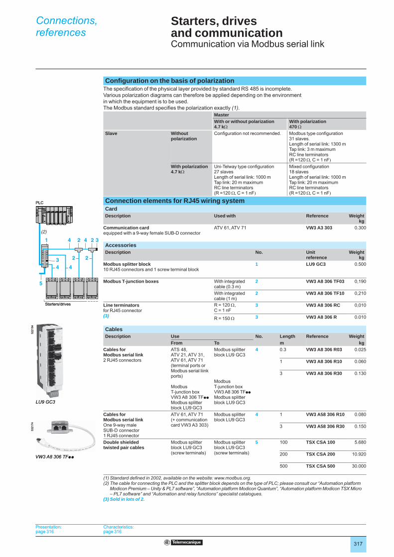
Confi guration on the basis of polarizationThe specifi cation of the physical layer provided by standard RS 485 is incomplete. Various polarization diagrams can therefore be applied depending on the environment in which the equipment is to be used.The Modbus standard specifi es the polarization exactly (1).
MasterWith or without polarization4.7 kΩ
With polarization470 Ω
Slave Without polarization
Confi guration not recommended. Modbus type confi guration31 slaves.Length of serial link: 1300 mTap link: 3 m maximumRC line terminators (R =120 Ω, C = 1 nF)
With polarization4.7 kΩ
Uni-Telway type confi guration27 slavesLength of serial link: 1000 mTap link: 20 m maximumRC line terminators (R =120 Ω, C = 1 nF)
Mixed confi guration18 slavesLength of serial link: 1000 mTap link: 20 m maximumRC line terminators (R =120 Ω, C = 1 nF)
Connection elements for RJ45 wiring systemCardDescription Used with Reference Weight
kgCommunication cardequipped with a 9-way female SUB-D connector
ATV 61, ATV 71 VW3 A3 303 0.300
AccessoriesDescription No. Unit
referenceWeight
kgModbus splitter block10 RJ45 connectors and 1 screw terminal block
1 LU9 GC3 0.500
Modbus T-junction boxes With integrated cable (0.3 m)
2 VW3 A8 306 TF03 0,190
With integrated cable (1 m)
2 VW3 A8 306 TF10 0,210
Line terminatorsfor RJ45 connector(3)
R = 120 Ω, C = 1 nF
3 VW3 A8 306 RC 0,010
R = 150 Ω 3 VW3 A8 306 R 0.010
CablesDescription Use No. Length Reference Weight
From To m kgCables for Modbus serial link2 RJ45 connectors
ATS 48,ATV 21, ATV 31,ATV 61, ATV 71(terminal ports or Modbus serial liink ports)
Modbus T-junction box VW3 A8 306 TFppModbus splitter block LU9 GC3
Modbus splitter block LU9 GC3
Modbus T-junction box VW3 A8 306 TFppModbus splitter block LU9 GC3
4 0.3 VW3 A8 306 R03 0.025
1 VW3 A8 306 R10 0.060
3 VW3 A8 306 R30 0.130
Cables for Modbus serial linkOne 9-way male SUB-D connector 1 RJ45 connector
ATV 61, ATV 71 (+ communication card VW3 A3 303)
Modbus splitter block LU9 GC3
4 1 VW3 A58 306 R10 0.080
3 VW3 A58 306 R30 0.150
Double shielded twisted pair cables
Modbus splitter block LU9 GC3(screw terminals)
Modbus splitter block LU9 GC3(screw terminals)
5 100 TSX CSA 100 5.680
200 TSX CSA 200 10.920
500 TSX CSA 500 30.000
(1) Standard defi ned in 2002, available on the website: www.modbus.org.(2) The cable for connecting the PLC and the splitter block depends on the type of PLC; please consult our “Automation platform
Modicon Premium – Unity & PL7 software”, “Automation platform Modicon Quantum”, “Automation platform Modicon TSX Micro – PL7 software” and “Automation and relay functions” specialist catalogues.
(3) Sold in lots of 2.
34
2 2
4
41
5
42 2 3
(2)
Starters/drives
PLC
34
2 2
4
41
5
42 2 3
(2)
Starters/drives
PLC
LU9 GC3
5221
84
LU9 GC3
5221
84
VW3 A8 306 TFpp
5321
74
VW3 A8 306 TFpp
5321
74
Presentation:page 316
Characteristics:page 316
Presentation:page 316
Characteristics:page 316
Presentation:page 316
Characteristics:page 316
Presentation:page 316
Characteristics:page 316
Connections,references 1

318
Starters, drives and communication 1 Communication via Modbus serial link
Connection elements using tap junctionsAccessoriesDescription No. Reference Weight
kgTap junction3 screw terminals, RC line terminator
1 TSX SCA 50 0.520
Subscriber socketTwo 15-way female SUB-D connectors and 2 screw terminals, RC line terminator
2 TSX SCA 62 0.570
CablesDescription Use No. Length Reference Weight
From To m kgDouble shielded twisted pair cables
Tap junction TSX SCA 50,subscriber socket TSX SCA 62
Tap junction TSX SCA 50,subscriber socket TSX SCA 62
3 100 TSX CSA 100 5.680
200 TSX CSA 200 10.920
500 TSX CSA 500 30.000
Cable for Modbus serial link1 RJ45 connector and one stripped end
ATS 48,ATV 21, ATV 31,ATV 61, ATV 71(terminal ports or Modbus serial link ports)
Tap junction TSX SCA 50
4 3 VW3 A8 306 D30 0.150
Cable for Modbus serial link1 RJ45 connector and one 15-way male SUB-D connector
ATS 48,ATV 21, ATV 31,ATV 61, ATV 71(terminal ports or Modbus serial link ports)
Subscriber socket TSX SCA 62
5 3 VW3 A8 306 0.150
Cable for Uni-Telway and Modbus serial link2 male SUB-D connectors, 9 and 15-way
ATV 61, ATV 71 (+ communication card VW3 A3 303)
Subscriber socket TSX SCA 62
5 3 VW3 A8 306 2 0.150
(1) The cable for connecting the PLC and the splitter block depends on the type of PLC; please consult our “Automation platform Modicon Premium - Unity & PL7 software”, “Automation platform Modicon Quantum”, “Automation platform Modicon TSX Micro – PL7 software” and “Automation and relay functions” specialist catalogues.
3
5 4
2 1(1)
Starters/drives
PLC
3
5 4
2 1(1)
Starters/drives
PLC
TSX SCA 50
5331
78
TSX SCA 50
5331
78
TSX SCA 62
5331
79
TSX SCA 62
5331
79
Presentation:page 316
Characteristics:page 316
Presentation:page 316
Characteristics:page 316
Presentation:page 316
Characteristics:page 316
Presentation:page 316
Characteristics:page 316
Connections,references (continued) 1
319
Starters, drives and communication 1 Communication via Modbus serial link
Connection elements using screw terminalsAccessoriesDescription Sold in
lots ofReferenceunit
Weightkg
Line terminatorsfor screw terminals
R = 120 Ω, C = 1 nF
2 VW3 A8 306 DRC 0.200
R = 150 Ω 2 VW3 A8 306 DR 0.200
CableDescription Use Length Reference Weight
From To m kgCable for Modbus1 RJ45 connector and one stripped end
ATS 48,ATV 21, ATV 31,ATV 61, ATV 71(terminal ports or Modbus serial link ports)
Standard screw terminal,tap junction TSX SCA 50
3 VW3 A8 306 D30 0.150
DocumentationThe manuals and quick reference guides for starters and variable speed drives, as well as the user manuals for communication gateways, are available on the website: www.telemecanique.com.
Presentation:page 316
Characteristics:page 316
Connections:pages 317 and 318
Presentation:page 316
Characteristics:page 316
Connections:pages 317 and 318
Presentation:page 316
Characteristics:page 316
Connections:pages 317 and 318
Presentation:page 316
Characteristics:page 316
Connections:pages 317 and 318
References (continued) 1
320
Starters, drives and communication1 Communication via Modbus Plus network
Presentation
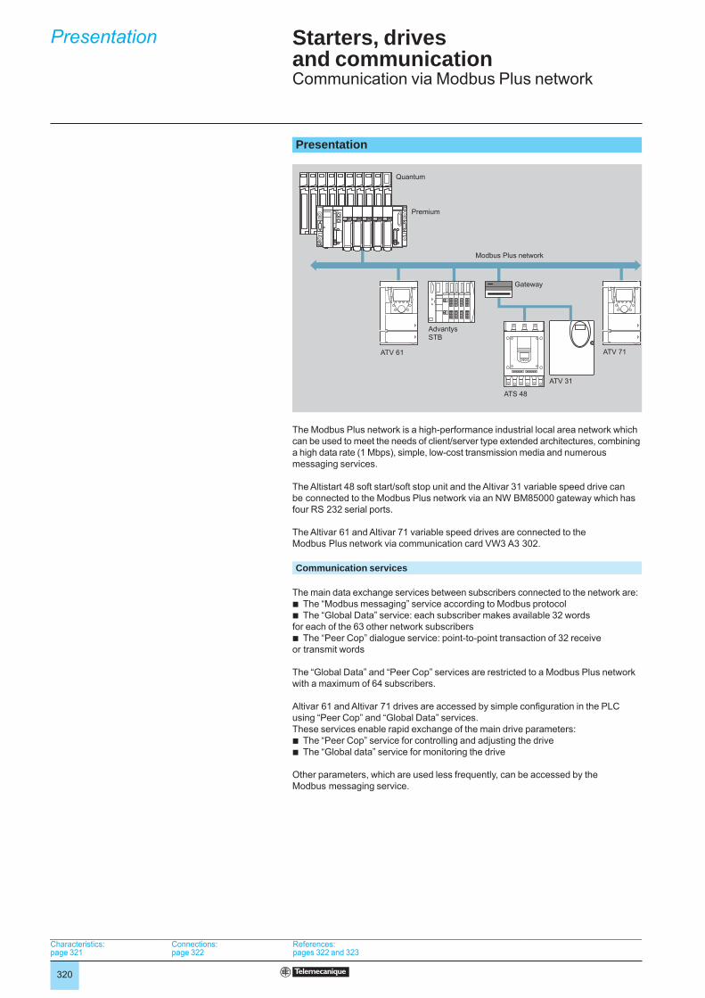
The Modbus Plus network is a high-performance industrial local area network which can be used to meet the needs of client/server type extended architectures, combining a high data rate (1 Mbps), simple, low-cost transmission media and numerous messaging services.
The Altistart 48 soft start/soft stop unit and the Altivar 31 variable speed drive can be connected to the Modbus Plus network via an NW BM85000 gateway which has four RS 232 serial ports.
The Altivar 61 and Altivar 71 variable speed drives are connected to the Modbus Plus network via communication card VW3 A3 302.
Communication services
The main data exchange services between subscribers connected to the network are:b The “Modbus messaging” service according to Modbus protocolb The “Global Data” service: each subscriber makes available 32 words for each of the 63 other network subscribersb The “Peer Cop” dialogue service: point-to-point transaction of 32 receive or transmit words
The “Global Data” and “Peer Cop” services are restricted to a Modbus Plus network with a maximum of 64 subscribers.
Altivar 61 and Altivar 71 drives are accessed by simple confi guration in the PLC using “Peer Cop” and “Global Data” services.These services enable rapid exchange of the main drive parameters:b The “Peer Cop” service for controlling and adjusting the driveb The “Global data” service for monitoring the drive
Other parameters, which are used less frequently, can be accessed by the Modbus messaging service.
Modbus Plus network
Quantum
ATV 61
ATS 48
ATV 71
Premium
Advantys STB
Gateway
ATV 31
Modbus Plus network
Quantum
ATV 61
ATS 48
ATV 71
Premium
Advantys STB
Gateway
ATV 31
Characteristics: page 321
Connections:page 322
References: pages 322 and 323
Characteristics: page 321
Connections:page 322
References: pages 322 and 323
Characteristics: page 321
Connections:page 322
References: pages 322 and 323
Characteristics: page 321
Connections:page 322
References: pages 322 and 323
Presentation1
321
Starters, drives and communication1 Communication via Modbus Plus network
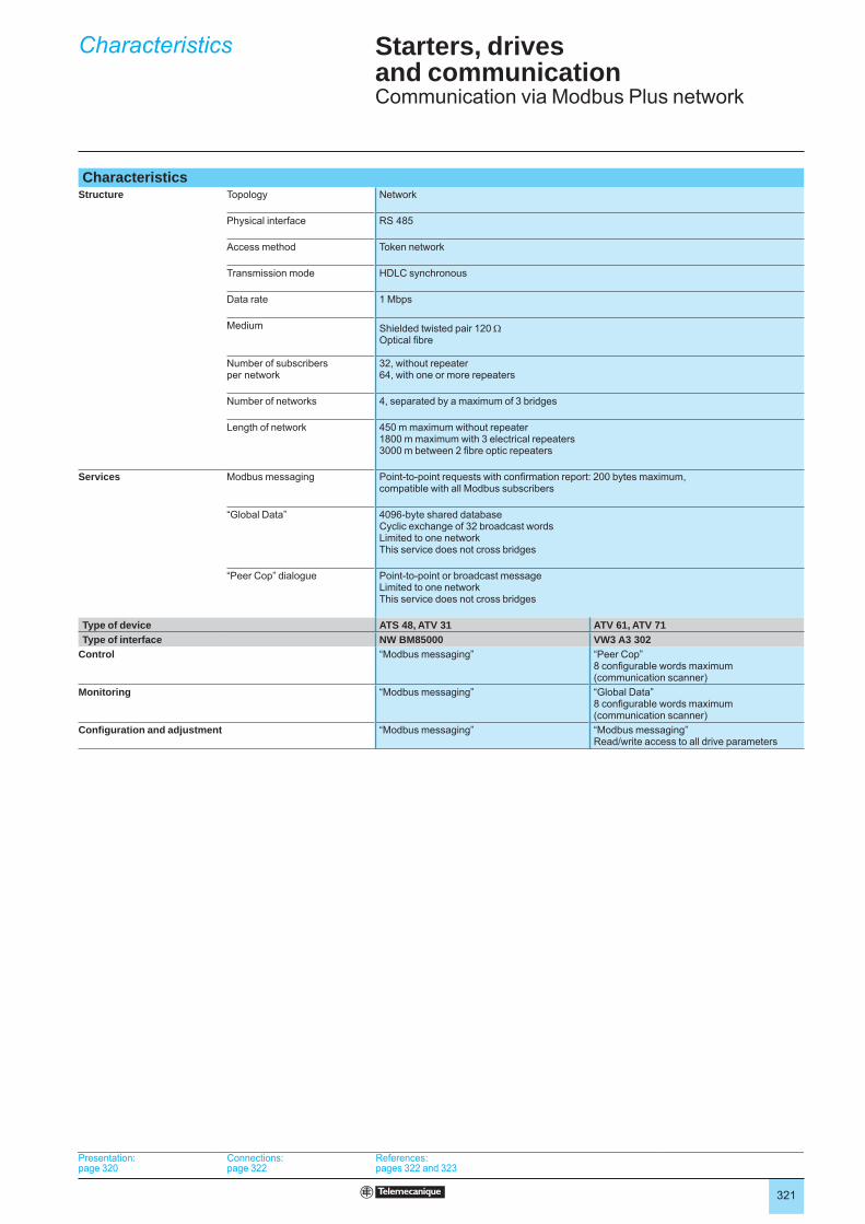
CharacteristicsStructure Topology Network
Physical interface RS 485
Access method Token network
Transmission mode HDLC synchronous
Data rate 1 Mbps
Medium Shielded twisted pair 120 Ω Optical fi bre
Number of subscribers per network
32, without repeater64, with one or more repeaters
Number of networks 4, separated by a maximum of 3 bridges
Length of network 450 m maximum without repeater1800 m maximum with 3 electrical repeaters3000 m between 2 fi bre optic repeaters
Services Modbus messaging Point-to-point requests with confi rmation report: 200 bytes maximum, compatible with all Modbus subscribers
“Global Data” 4096-byte shared databaseCyclic exchange of 32 broadcast wordsLimited to one networkThis service does not cross bridges
“Peer Cop” dialogue Point-to-point or broadcast messageLimited to one networkThis service does not cross bridges
Type of device ATS 48, ATV 31 ATV 61, ATV 71Type of interface NW BM85000 VW3 A3 302
Control “Modbus messaging” “Peer Cop”8 confi gurable words maximum (communication scanner)
Monitoring “Modbus messaging” “Global Data”8 confi gurable words maximum (communication scanner)
Confi guration and adjustment “Modbus messaging” “Modbus messaging”Read/write access to all drive parameters
Presentation: page 320
Connections:page 322
References: pages 322 and 323
Presentation: page 320
Connections:page 322
References: pages 322 and 323
Presentation: page 320
Connections:page 322
References: pages 322 and 323
Presentation: page 320
Connections:page 322
References: pages 322 and 323
Characteristics1
322
Starters, drives and communication1 Communication via Modbus Plus network
Modbus Plus wiring system
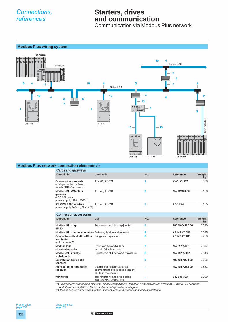
Modbus Plus network connection elements (1)Cards and gatewaysDescription Used with No. Reference Weight
kgCommunication cardsequipped with one 9-way female SUB-D connector
ATV 61, ATV 71 1 VW3 A3 302 0.300
Modbus Plus/Modbus gateway4 RS 232 portspower supply 115…220 V a
ATS 48, ATV 31 2 NW BM85000 3.158
RS 232/RS 485 interfacepower supply 24 V c, 20 mA (2)
ATS 48, ATV 31 3 XGS Z24 0.105
Connection accessoriesDescription Use No. Reference Weight
kgModbus Plus tap(IP 20)
For connecting via a tap junction 4 990 NAD 230 00 0.230
Modbus Plus in-line connector Gateway, bridge and repeater 5 AS MBKT 085 0.035Connector with Modbus Plus terminator(sold in lots of 2)
Bridge and repeater 6 AS MBKT 185 0.260
Modbus Plus electrical repeater
Extension beyond 450 m or up to 64 subscribers
7 NW RR85 001 2.677
Modbus Plus bridge with 4 ports
Connection of 4 networks maximum 8 NW BP85 002 2.813
Line/station fi bre-optic repeater
– 9 490 NRP 254 00 2.856
Point-to-point fi bre-optic repeater
Used to connect an electrical segment to the fi bre-optic segment (3000 m maximum)
– NW NRP 253 00 2.863
Wiring tool Inserting trunk and drop cables in a 990 NAD 230 00 tap
– 043 509 383 3.000
(1) To order other connection elements, please consult our “Automation platform Modicon Premium – Unity & PL7 software” and “Automation platform Modicon Quantum” specialist catalogues.
(2) Please consult our “Power supplies, splitter blocks and interfaces” specialist catalogue.
RS 232RS 485
7
1313
126
12 2
13
3
11
11
1
6
9
10
11
11
10 4
10 54 4 4
44
8
1
Network # 1
Network # 2Premium
Quantum
ATV 31ATS 48
ATV 71
Quantum
Fibr
e op
tic li
nk
ATV 61
RS 232RS 485
7
1313
126
12 2
13
3
11
11
1
6
9
10
11
11
10 4
10 54 4 4
44
8
1
Network # 1
Network # 2Premium
Quantum
ATV 31ATS 48
ATV 71
Quantum
Fibr
e op
tic li
nk
ATV 61
Presentation: page 320
Characteristics: page 321
Presentation: page 320
Characteristics: page 321
Presentation: page 320
Characteristics: page 321
Presentation: page 320
Characteristics: page 321
Connections,references1
323
Starters, drives and communication1 Communication via Modbus Plus network
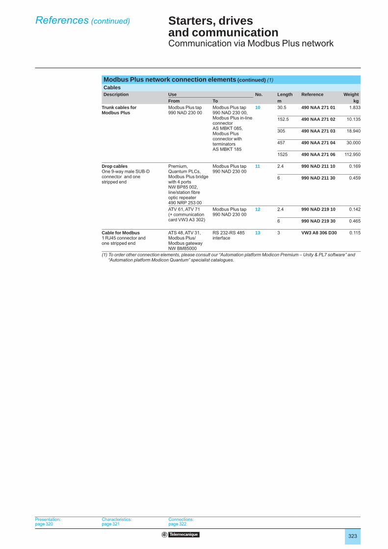
Modbus Plus network connection elements (continued) (1)CablesDescription Use No. Length Reference Weight
From To m kgTrunk cables for Modbus Plus
Modbus Plus tap 990 NAD 230 00
Modbus Plus tap 990 NAD 230 00,Modbus Plus in-line connector AS MBKT 085,Modbus Plus connector with terminatorsAS MBKT 185
10 30.5 490 NAA 271 01 1.833
152.5 490 NAA 271 02 10.135
305 490 NAA 271 03 18.940
457 490 NAA 271 04 30.000
1525 490 NAA 271 06 112.950
Drop cablesOne 9-way male SUB-D connector and one stripped end
Premium, Quantum PLCs, Modbus Plus bridge with 4 ports NW BP85 002, line/station fi bre optic repeater 490 NRP 253 00
Modbus Plus tap 990 NAD 230 00
11 2.4 990 NAD 211 10 0.169
6 990 NAD 211 30 0.459
ATV 61, ATV 71 (+ communication card VW3 A3 302)
Modbus Plus tap 990 NAD 230 00
12 2.4 990 NAD 219 10 0.142
6 990 NAD 219 30 0.465
Cable for Modbus1 RJ45 connector and one stripped end
ATS 48, ATV 31, Modbus Plus/Modbus gateway NW BM85000
RS 232-RS 485interface
13 3 VW3 A8 306 D30 0.115
(1) To order other connection elements, please consult our “Automation platform Modicon Premium – Unity & PL7 software” and “Automation platform Modicon Quantum” specialist catalogues.
Presentation: page 320
Characteristics: page 321
Connections:page 322
Presentation: page 320
Characteristics: page 321
Connections:page 322
Presentation: page 320
Characteristics: page 321
Connections:page 322
Presentation: page 320
Characteristics: page 321
Connections:page 322
References (continued)1
324
Starters, drives and communication 3 Communication via Uni-Telway bus
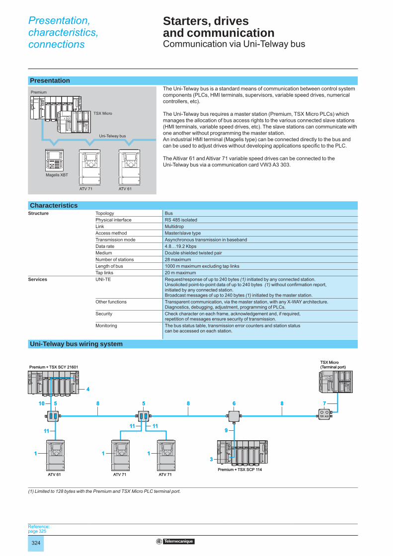
Presentation The Uni-Telway bus is a standard means of communication between control system
components (PLCs, HMI terminals, supervisors, variable speed drives, numerical controllers, etc).
The Uni-Telway bus requires a master station (Premium, TSX Micro PLCs) which manages the allocation of bus access rights to the various connected slave stations (HMI terminals, variable speed drives, etc). The slave stations can communicate with one another without programming the master station. An industrial HMI terminal (Magelis type) can be connected directly to the bus and can be used to adjust drives without developing applications specifi c to the PLC.
The Altivar 61 and Altivar 71 variable speed drives can be connected to the Uni-Telway bus via a communication card VW3 A3 303.
CharacteristicsStructure Topology Bus
Physical interface RS 485 isolatedLink MultidropAccess method Master/slave typeTransmission mode Asynchronous transmission in basebandData rate 4.8…19.2 KbpsMedium Double shielded twisted pairNumber of stations 28 maximumLength of bus 1000 m maximum excluding tap linksTap links 20 m maximum
Services UNI-TE Request/response of up to 240 bytes (1) initiated by any connected station.Unsolicited point-to-point data of up to 240 bytes (1) without confi rmation report, initiated by any connected station.Broadcast messages of up to 240 bytes (1) initiated by the master station.
Other functions Transparent communication, via the master station, with any X-WAY architecture.Diagnostics, debugging, adjustment, programming of PLCs.
Security Check character on each frame, acknowledgement and, if required, repetition of messages ensure security of transmission.
Monitoring The bus status table, transmission error counters and station status can be accessed on each station.
Uni-Telway bus wiring system
(1) Limited to 128 bytes with the Premium and TSX Micro PLC terminal port.
ATV 71 ATV 61
Magelis XBT
TSX Micro
Premium
Uni-Telway bus
ATV 71 ATV 61
Magelis XBT
TSX Micro
Premium
Uni-Telway bus
8 88 710
119
3
655
1111
11 1
4
TSX Micro(Terminal port)
Premium + TSX SCP 114ATV 61 ATV 71
Premium + TSX SCY 21601
ATV 71
8 88 710
119
3
655
1111
11 1
4
TSX Micro(Terminal port)
Premium + TSX SCP 114ATV 61 ATV 71
Premium + TSX SCY 21601
ATV 71
Presentation,characteristics,connections
Reference: page 325Reference: page 325
325
Starters, drives and communication 3 Communication via Uni-Telway bus
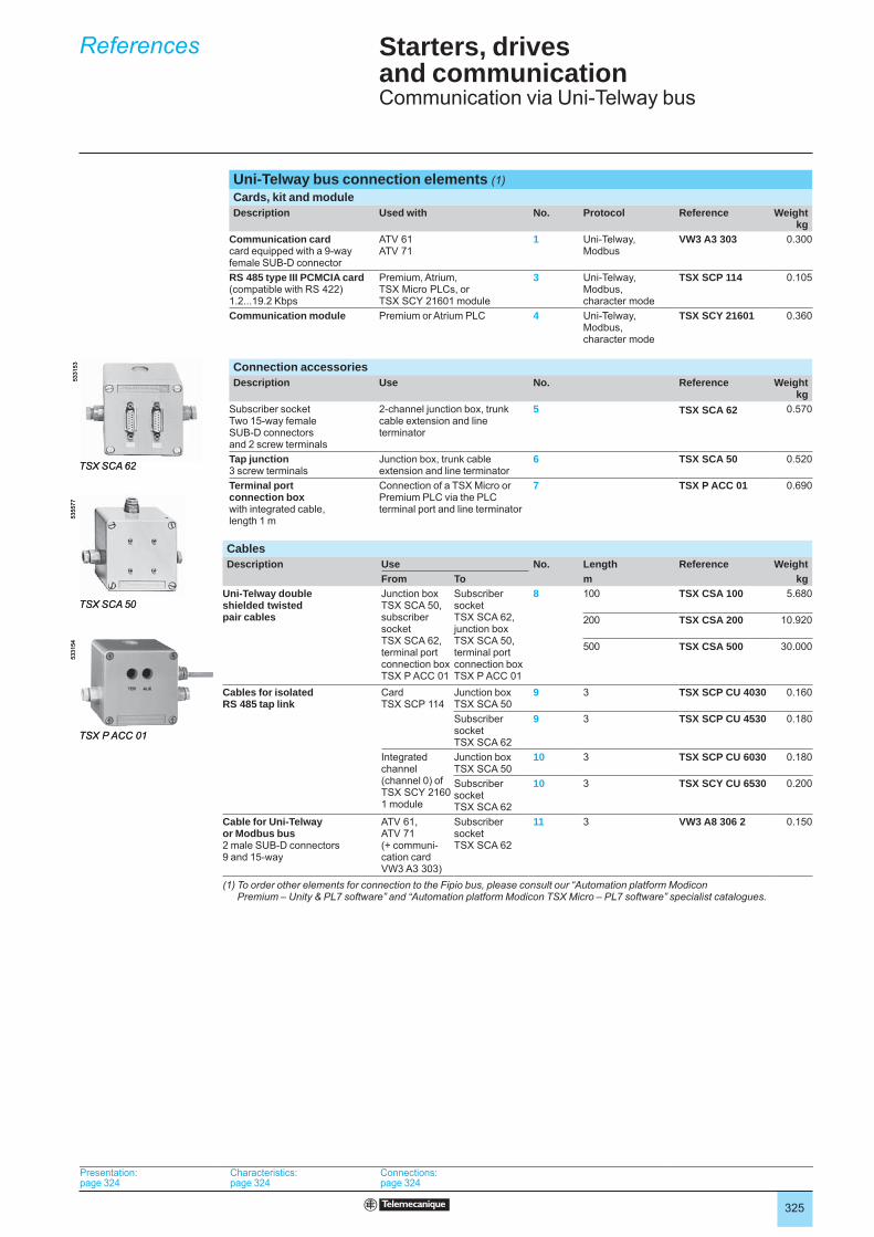
Uni-Telway bus connection elements (1)Cards, kit and moduleDescription Used with No. Protocol Reference Weight
kgCommunication cardcard equipped with a 9-way female SUB-D connector
ATV 61ATV 71
1 Uni-Telway, Modbus
VW3 A3 303 0.300
RS 485 type III PCMCIA card(compatible with RS 422)1.2...19.2 Kbps
Premium, Atrium, TSX Micro PLCs, or TSX SCY 21601 module
3 Uni-Telway, Modbus, character mode
TSX SCP 114 0.105
Communication module Premium or Atrium PLC 4 Uni-Telway, Modbus, character mode
TSX SCY 21601 0.360
Connection accessoriesDescription Use No. Reference Weight
kgSubscriber socketTwo 15-way female SUB-D connectors and 2 screw terminals
2-channel junction box, trunk cable extension and line terminator
5 TSX SCA 62 0.570
Tap junction3 screw terminals
Junction box, trunk cable extension and line terminator
6 TSX SCA 50 0.520
Terminal port connection box with integrated cable,length 1 m
Connection of a TSX Micro or Premium PLC via the PLC terminal port and line terminator
7 TSX P ACC 01 0.690
CablesDescription Use No. Length Reference Weight
From To m kgUni-Telway double shielded twisted pair cables
Junction box TSX SCA 50, subscriber socket TSX SCA 62, terminal port connection box TSX P ACC 01
Subscriber socket TSX SCA 62, junction box TSX SCA 50, terminal port connection box TSX P ACC 01
8 100 TSX CSA 100 5.680
200 TSX CSA 200 10.920
500 TSX CSA 500 30.000
Cables for isolated RS 485 tap link
Card TSX SCP 114
Junction box TSX SCA 50
9 3 TSX SCP CU 4030 0.160
Subscriber socket TSX SCA 62
9 3 TSX SCP CU 4530 0.180
Integrated channel (channel 0) of TSX SCY 21601 module
Junction box TSX SCA 50
10 3 TSX SCP CU 6030 0.180
Subscriber socket TSX SCA 62
10 3 TSX SCY CU 6530 0.200
Cable for Uni-Telway or Modbus bus2 male SUB-D connectors 9 and 15-way
ATV 61, ATV 71(+ communi -cation card VW3 A3 303)
Subscriber socket TSX SCA 62
11 3 VW3 A8 306 2 0.150
(1) To order other elements for connection to the Fipio bus, please consult our “Automation platform Modicon Premium – Unity & PL7 software” and “Automation platform Modicon TSX Micro – PL7 software” specialist catalogues.
TSX SCA 62
5331
53
TSX SCA 62
5331
53
TSX SCA 50
5355
77
TSX SCA 50
5355
77
TSX P ACC 01
5331
54
TSX P ACC 01
5331
54
References
Presentation: page 324
Characteristics: page 324
Connections:page 324
Presentation: page 324
Characteristics: page 324
Connections:page 324
326
TeSys motor starters - open version 0 Communication gateways LUF P
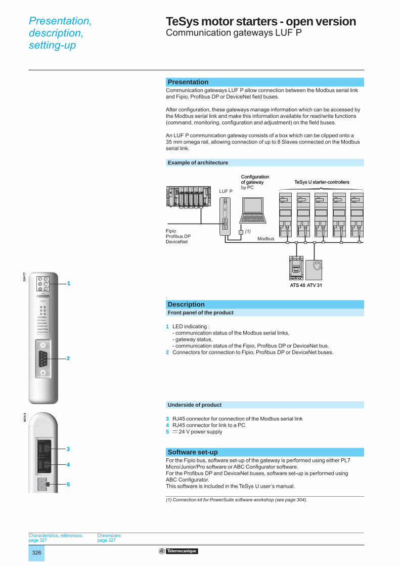
PresentationCommunication gateways LUF P allow connection between the Modbus serial link and Fipio, Profi bus DP or DeviceNet fi eld buses.
After confi guration, these gateways manage information which can be accessed by the Modbus serial link and make this information available for read/write functions (command, monitoring, confi guration and adjustment) on the fi eld buses.
An LUF P communication gateway consists of a box which can be clipped onto a 35 mm omega rail, allowing connection of up to 8 Slaves connected on the Modbus serial link.
Example of architecture
. DescriptionFront panel of the product
1 LED indicating :- communication status of the Modbus serial links,- gateway status,- communication status of the Fipio, Profi bus DP or DeviceNet bus.
2 Connectors for connection to Fipio, Profi bus DP or DeviceNet buses.
Underside of product
3 RJ45 connector for connection of the Modbus serial link4 RJ45 connector for link to a PC5 c 24 V power supply
Software set-up
For the Fipio bus, software set-up of the gateway is performed using either PL7 Micro/Junior/Pro software or ABC Confi gurator software.For the Profi bus DP and DeviceNet buses, software set-up is performed using ABC Confi gurator.This software is included in the TeSys U user’s manual.
(1) Connection kit for PowerSuite software workshop (see page 304).
Confi gurationof gatewayby PC
TeSys U starter-controllers
Fipio Profi bus DP DeviceNet
LUF P
ATS 48 ATV 31
(1)Modbus
Confi gurationof gatewayby PC
TeSys U starter-controllers
Fipio Profi bus DP DeviceNet
LUF P
ATS 48 ATV 31
(1)Modbus
5241
7756
1512
1
2
3
5
4
5241
7756
1512
1
2
3
5
4
Characteristics, references:page 327
Dimensions:page 327
Characteristics, references:page 327
Dimensions:page 327
Characteristics, references:page 327
Dimensions:page 327
Characteristics, references:page 327
Dimensions:page 327
Presentation,description,setting-up 0
327
TeSys motor starters - open version 0 Communication gateways LUF P
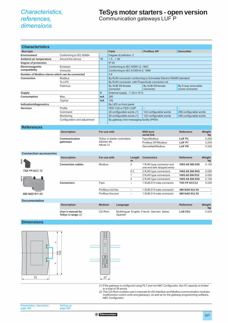
CharacteristicsBus type Fipio Profi bus DP DeviceNet
Environment Conforming to IEC 60664 Degree of pollution: 2Ambient air temperature Around the device °C + 5…+ 50Degree of protection IP 20Electromagneticcompatibility
Emission Conforming to IEC 50081-2: 1993Immunity Conforming to IEC 61000-6-2: 1999
Number of Modbus slaves which can be connected y 8Connection Modbus By RJ45 connector conforming to Schneider Electric RS485 standard
To a PC By RJ45 connector, with PowerSuite connection kitField bus By SUB D9 female
connectorBy SUB D9 female connector
By 5-way removablescrew connector
Supply V External supply, c 24 ± 10 %Consumption Max. mA 280
Typical mA 100Indication/diagnostics By LED on front panelServices Profi le FED C32 or FED C32P – –
Command 26 confi gurable words (1) 122 confi gurable words 256 confi gurable wordsMonitoring 26 confi gurable words (1) 122 confi gurable words 256 confi gurable wordsConfi guration and adjustment By gateway mini messaging facility (PKW)
ReferencesDescription For use with With bus/
serial linkReference Weight
kgCommunicationgateways
TeSys U starter-controllers,Altistart 48, Altivar 31
Fipio/Modbus LUF P1 0.245Profi bus DP/Modbus LUF P7 0.245DeviceNet/Modbus LUF P9 0.245
Connection accessoriesDescription For use with Length
mConnectors Reference Weight
kgConnection cables Modbus 3 1 RJ45 type connector and
one end with stripped wiresVW3 A8 306 D30 0.150
0.3 2 RJ45 type connectors VW3 A8 306 R03 0.0501 2 RJ45 type connectors VW3 A8 306 R10 0.0503 2 RJ45 type connectors VW3 A8 306 R30 0.150
Connectors Fipio – 1 SUB-D 9 male connector TSX FP ACC12 0.040
Profi bus mid line – 1 SUB-D 9 male connector 490 NAD 911 04 –Profi bus line end – 1 SUB-D 9 male connector 490 NAD 911 03 –
DocumentationDescription Medium Language Reference Weight
kgUser’s manual forTeSys U range (2)
CD-Rom Multilingual: English, French, German, Italian, Spanish
LU9 CD1 0.022
Dimensions
(1) If the gateway is confi gured using PL7 and not ABC Confi gurator, the I/O capacity is limitedto a total of 26 words.
(2) This CD-Rom contains user’s manuals for AS-Interface and Modbus communication modules, multifunction control units and gateways, as well as for the gateway programming software, ABC Confi gurator.
8226
31
TSX FP ACC 12
8226
31
TSX FP ACC 12
490 NAD 911 03
8227
13
490 NAD 911 03
8227
13
75 27
120
==
75 27
120
==
Presentation, description:page 326
Setting-up:page 326
Presentation, description:page 326
Setting-up:page 326
Presentation, description:page 326
Setting-up:page 326
Presentation, description:page 326
Setting-up:page 326
Presentation, description:page 326
Setting-up:page 326
Presentation, description:page 326
Setting-up:page 326
Presentation, description:page 326
Setting-up:page 326
Presentation, description:page 326
Setting-up:page 326
Characteristics,references,dimensions 0
328
043 509 383 318490 NAD 911 03 323
and 325490 NAD 911 04 323
and 325490 NAA 271 0p 319490 NRP 254 00 318490 NTC 000 pp 310490 NTW 000 pp 310499 NEH 104 10 311499 NEH 141 00 311499 NES 181 00 311499 NES 251 00 311499 NMS 251 0p 311499 NOH 105 10 311499 NSS 251 0p 311990 NAD 211 10 319990 NAD 211 30 319990 NAD 219 pp 319990 NAD 230 00 318
AAS MBKT ppp 318ATV 71H037M3 22ATV 71H075M3 22ATV 71H075N4 23ATV 71HC11N4 23ATV 71HC11Y 25ATV 71HC13N4 23ATV 71HC13Y 25ATV 71HC16N4 23ATV 71HC16Y 25ATV 71HC20N4 23ATV 71HC20Y 25ATV 71HC25N4 23ATV 71HC25Y 25ATV 71HC28N4 23ATV 71HC31N4 23ATV 71HC31Y 25ATV 71HC40N4 23ATV 71HC40Y 25ATV 71HC50N4 23ATV 71HC50Y 25ATV 71HC63Y 25ATV 71HD11M3X 22ATV 71HD11N4 23ATV 71HD11Y 25ATV 71HD15M3X 22ATV 71HD15N4 23ATV 71HD15Y 25ATV 71HD18M3X 22ATV 71HD18N4 23ATV 71HD18Y 25ATV 71HD22M3X 22ATV 71HD22N4 23ATV 71HD22Y 25ATV 71HD30N4 23ATV 71HD30Y 25ATV 71HD37N4 23ATV 71HD37Y 25ATV 71HD45N4 23ATV 71HD45Y 25ATV 71HD55N4 23ATV 71HD55Y 25ATV 71HD75N4 23ATV 71HD75Y 25ATV 71HD90N4 23ATV 71HD90Y 25ATV 71HU15M3 22ATV 71HU22M3 22ATV 71HU22N4 23
ATV 71HU22Y 25ATV 71HU30M3 22ATV 71HU30N4 23ATV 71HU40M3 22ATV 71HU40N4 23ATV 71HU40Y 25ATV 71HU55M3 22ATV 71HU55N4 23ATV 71HU55Y 25ATV 71HU75M3 22ATV 71HU75N4 23ATV 71HU75Y 25ATV 71P075N4Z 24ATV 71PD11N4Z 24ATV 71PU22N4Z 24ATV 71PU30N4Z 24ATV 71PU40N4Z 24ATV 71PU55N4Z 24ATV 71PU75N4Z 24ATV 71HC11Y 248ATV 71HC13Y 248ATV 71HC16Y 248ATV 71HC20Y 248ATV 71HC25Y 249ATV 71HC31Y 249ATV 71HC40Y 249ATV 71HC50Y 249ATV 71HC63Y 249ATV 71HD11Y 248ATV 71HD15Y 248ATV 71HD18Y 248ATV 71HD22Y 248ATV 71HD30M3X 22ATV 71HD30Y 248ATV 71HD37M3X 22ATV 71HD37Y 248ATV 71HD45M3X 22ATV 71HD45Y 248ATV 71HD55M3X 22ATV 71HD55Y 248ATV 71HD75M3X 22ATV 71HD75Y 248ATV 71HD90Y 248ATV 71HU15N4 23ATV 71HU22Y 248ATV 71HU30Y 25
and 248ATV 71HU40Y 248ATV 71HU55Y 248ATV 71HU75Y 248ATV 71P075N4Z 247ATV 71PU15N4Z 24ATV 71PU22N4Z 247ATV 71PU30N4Z 247ATV 71PU40N4Z 247ATV 71PU55N4Z 247ATV 71PU75N4Z 247ATV 71W075N4 24
and 246ATV 71WD11N4 24
and 246ATV 71WD15N4 24
and 246ATV 71WD18N4 24
and 246ATV 71WD22N4 24
and 246ATV 71WD30N4 24
and 246ATV 71WD37N4 24
and 246
ATV 71WD45N4 24and 246
ATV 71WD55N4 24and 246
ATV 71WD75N4 24and 246
ATV 71WU15N4 24and 246
ATV 71WU22N4 24and 246
ATV 71WU30N4 24and 246
ATV 71WU40N4 24and 246
ATV 71WU55N4 24and 246
ATV 71WU75N4 24and 246
LLA9 P307 325LU9 CD1 323LU9 GC3 109,133
and 315LUF P1 314
and 323LUF P7 323LUF P9 323
NNW RR85 001 318NW BM85000 318NW BP85 002 318NW NRP 253 00 318
TTCS EAK 0100 310TCS EAQ 0100 310TCS ESM083F23F0 311TCS ESM083F2CS0 311TCS ESM083F2CU0 311TSX CAN CA 100 123
and 133TSX CAN CA 300 123
and 133TSX CAN CA 50 1123
and 133TSX CAN CB 100 123
and 133TSX CAN CB 300 123
and 133TSX CAN CB 50 123
and 133TSX CAN CD 100 123
and 133TSX CAN CD 300 123
and 133TSX CAN CD 50 123
and 133TSX FP ACC12 315
and 323TSX FP ACC14 315TSX FP ACC6 315TSX FP ACC7 315TSX FP ACC8M 315TSX FP ACC9 315TSX CAN KCDF 123TSX CSA 100 321TSX CSA 200 321TSX CSA 500 321TSX ETG 100 310
TSX FP CA100 315TSX FP CA200 315TSX FP CA500 315TSX FP CC100 315TSX FP CC200 315TSX FP CC500 315TSX FP CR100 315TSX FP CR200 315TSX FP CR500 315TSX FP JF020 315TSX P ACC 01 321TSX SCA 50 321TSX SCA 62 321TSX SCP 114 321TSX SCP CU 4030 321TSX SCP CU 4530 321TSX SCP CU 6030 321TSX SCY 21601 321TSX SCY CU 6530 321
VVW3 A1 101 108VW3 A1 102 108
and 109VW3 A1 103 108VW3 A1 104 R10 108
and 109VW3 A1 104 R100 108
and 109VW3 A1 104 R30 108
and 109VW3 A1 104 R50 108
and 109VW3 A1 105 108VW3 A3 101 26VW3 A3 201 115VW3 A3 202 115VW3 A3 301 132
and 314VW3 A3 302 132
and 318VW3 A3 303 132
and 321VW3 A3 304 132VW3 A3 307 132VW3 A3 309 132VW3 A3 310 132
and 314VW3 A3 311 132
and 314VW3 A3 316 132VW3 A3 317 132VW3 A3 40p 113VW3 A3 411 113
and 168VW3 A3 501 123VW3 A4 401 168VW3 A4 402 168VW3 A4 403 168VW3 A4 404 168VW3 A4 405 168VW3 A4 406 168VW3 A4 407 168VW3 A4 408 168VW3 A4 410 168VW3 A4 412 168VW3 A4 413 168VW3 A4 501 155VW3 A4 502 155VW3 A4 503 155VW3 A4 504 155
VW3 A4 505 155VW3 A4 506 155VW3 A4 507 155VW3 A4 508 155VW3 A4 509 155VW3 A4 510 155VW3 A4 511 155VW3 A4 512 155VW3 A4 551 160VW3 A4 552 160VW3 A4 553 160VW3 A4 554 160VW3 A4 555 160VW3 A4 556 160VW3 A4 557 160VW3 A4 558 160VW3 A4 559 160VW3 A4 560 160VW3 A4 561 160VW3 A4 562 160VW3 A4 563 160VW3 A4 564 160VW3 A4 565 160VW3 A4 568 160VW3 A4 569 160VW3 A4 570 160VW3 A4 571 160VW3 A4 572 160VW3 A4 601 162VW3 A4 602 162VW3 A4 603 162VW3 A4 604 162VW3 A4 605 162VW3 A4 606 162VW3 A4 607 162VW3 A4 608 162VW3 A4 609 162VW3 A4 610 162VW3 A4 611 162VW3 A4 612 162VW3 A4 613 162VW3 A4 619 162VW3 A4 621 163VW3 A4 622 163VW3 A4 623 163VW3 A4 624 163VW3 A4 625 163VW3 A4 626 163VW3 A4 627 163VW3 A4 628 163VW3 A4 629 163VW3 A4 630 163VW3 A4 631 163VW3 A4 632 163VW3 A4 633 163VW3 A4 639 163VW3 A4 641 164VW3 A4 642 164VW3 A4 643 164VW3 A4 644 164VW3 A4 645 164VW3 A4 646 164VW3 A4 647 164VW3 A4 648 164VW3 A4 649 164VW3 A4 650 164VW3 A4 651 164VW3 A4 656 164VW3 A4 657 164VW3 A4 661 165VW3 A4 662 165
Product reference index
329
VW3 A4 663 165VW3 A4 664 165VW3 A4 665 165VW3 A4 666 165VW3 A4 667 165VW3 A4 668 165VW3 A4 669 165VW3 A4 670 165VW3 A4 671 165VW3 A4 676 165VW3 A4 677 165
VW3 A5 101 172and 173
VW3 A5 102 172and 173
VW3 A5 103 172and 173
VW3 A5 104 172and 173
VW3 A5 105 172and 173
VW3 A5 106 172and 173
VW3 A5 107 172and 173
VW3 A5 108 172and 173
VW3 A5 201 175VW3 A5 202 175VW3 A5 203 175VW3 A5 204 175VW3 A5 205 175VW3 A5 206 175VW3 A5 207 175VW3 A5 208 175VW3 A5 209 175VW3 A5 210 175VW3 A5 211 175VW3 A58501 160VW3 A58502 160VW3 A58502 160VW3 A7 101 135VW3 A7 102 135VW3 A7 103 135VW3 A7 104 135VW3 A7 201 149VW3 A7 202 149VW3 A7 203 149VW3 A7 204 149VW3 A7 205 149VW3 A7 206 149VW3 A7 207 149VW3 A7 208 149VW3 A7 209 149VW3 A7 210 149VW3 A7 211 149VW3 A7 212 149VW3 A7 231 149VW3 A7 232 149VW3 A7 233 149VW3 A7 234 149VW3 A7 235 149VW3 A7 236 149VW3 A7 237 149VW3 A7 238 149VW3 A7 239 149VW3 A7 240 149VW3 A7 241 149VW3 A7 701 137VW3 A7 702 137
VW3 A7 703 137VW3 A7 704 137VW3 A7 705 137VW3 A7 706 137VW3 A7 707 137VW3 A7 708 137VW3 A7 709 137VW3 A7 710 137VW3 A7 711 137VW3 A7 712 137VW3 A7 713 137VW3 A7 714 137VW3 A7 715 137VW3 A7 716 137VW3 A7 717 137VW3 A7 718 137VW3 A7 801 139VW3 A7 802 139VW3 A7 803 139VW3 A7 804 139VW3 A7 805 139VW3 A7 806 139VW3 A7 807 139VW3 A7 808 139VW3 A7 809 139VW3 A7 810 139VW3 A7 811 139VW3 A7 812 139VW3 A7 813 139VW3 A7 814 139VW3 A7 815 139VW3 A7 816 139VW3 A7 817 139VW3 A8 104 304VW3 A8 105 304VW3 A8 106 123
and 304VW3 A8 114 304VW3 A8 115 304VW3 A8 306 2 321VW3 A8 306 D30 310,
319, 323and 325
VW3 A8 306 R 133VW3 A8 306 R30 323VW3 A8 306 R03 109,
133, 315 and 323
VW3 A8 306 R10 109, 133, 315 and 323
VW3 A8 306 R30 109VW3 A8 306 RC 109,133
and 315VW3 A8 306 TF03 109VW3 A8 306 TF10 109VW3 A9 101 33VW3 A9 102 33VW3 A9 103 33VW3 A9 104 33VW3 A9 105 33VW3 A9 106 33VW3 A9 107 33VW3 A9 108 33VW3 A9 109 33VW3 A9 110 33VW3 A9 111 33VW3 A9 112 33VW3 A9 113 33VW3 A9 114 33VW3 A9 115 33
VW3 A9 116 33VW3 A9 117 33VW3 A9 201 32VW3 A9 202 32VW3 A9 203 32VW3 A9 204 32VW3 A9 205 32VW3 A9 206 32VW3 A9 207 32VW3 A9 208 32VW3 A9 209 32VW3 A9 210 32VW3 A9 211 32VW3 A9 212 32VW3 A9 213 32VW3 A9 214 32VW3 A9 217 32VW3 A9 301 34VW3 A9 302 34VW3 A9 303 34VW3 A9 304 34VW3 A9 305 34VW3 A9 306 34VW3 A9 307 34VW3 A9 308 34VW3 A9 309 34
and 35VW3 A9 310 34
and 35VW3 A9 312 34
and 35VW3 A9 314 34VW3 A9 404 27VW3 A9 405 27VW3 A9 406 27VW3 A9 407 27VW3 A9 501 30VW3 A9 502 30VW3 A9 503 30VW3 A9 504 30VW3 A9 505 30VW3 A9 506 30VW3 A9 507 30VW3 A9 508 30VW3 A9 509 30VW3 A9 510 30VW3 A9 511 30VW3 A9 512 30VW3 A9 513 30VW3 A9 514 30VW3 A9 515 30VW3 A9 541 39VW3 A9 542 39VW3 A9 543 39VW3 A9 544 39VW3 A9 545 39VW3 A9 546 39VW3 A9 547 39VW3 A9 548 39VW3 A9 549 39VW3 A9 550 39VW3 A9 551 39VW3 A9 601 169VW3 A9 602 169VW3 A9 612 173VW3 A9 613 173VW3 A9 621 28VW3 A9 622 28VW3 A9 623 28VW3 A9 624 28VW3 A9 625 28
VW3 A9 626 28VW3 A9 627 28VW3 A9 628 28VW3 A9 629 29VW3 A9 631 29VW3 A9 633 29VW3 A9 635 29VW3 A9 637 29VW3 A9 638 29VW3 A9 639 29VW3 A9 640 29VW3 A9 641 29VW3 A9 642 28VW3 A9 643 28VW3 A9 644 29VW3 A9 645 29VW3 A9 646 29VW3 A9 801 31VW3 A9 802 31VW3 A9 803 31VW3 A9 901 26VW3 A9 902 26VW3 A9 903 26VW3 A9 904 26VW3 A9 905 26VW3 A9 906 26VW3 A9 907 26VW3 CAN A71 123
and 133VW3 CAN KCDF 133VZ3 V1 ppp 31
XXGS Z24 304
and 318


ART. 805984 10 / 2007 - V3.0
DIA
2ED
2050
104E
N
Schneider Electric Industries SAS
The effi ciency of Telemecaniquebranded solutions Used in combination, Telemecanique products provide quality solutions, meeting all your Automation and Control applications requirements.
A worldwide presenceConstantly availableb More than 5 000 points of sale in 190 countries. b You can be sure to fi nd the range of products that are right for you and which complies fully with the standards in the country where they are used.
Technical assistance wherever you areb Our technicians are at your disposal to assist you in fi nding the optimum solution for your particular needs.b Schneider Electric provides you with all necessary technical assitance, throughout the world.
Simply Smart !Head Offi ce89, bd Franklin Roosevelt92506 Rueil-Malmaison CedexFrance
www.schneider-electric.com
Due to evolution of standards and equipment, the characteristics indicated in texts and images of this document do not constitute a commitment on our part without confi rmation.Design: Schneider ElectricPhotos: Schneider ElectricPrinted by: Ingoprint
Simple machinesAltistart 01: 0.37 to 75 kWAltivar 11: 0.18 to 2.2 kWAltivar 31: 0.18 to 15 kW
Complex, high power machinesAltivar 71 : 0.37 to 630 kW
Pumping and ventilationmachinesAltistart 48: 4 to 1 200 kWAltivar 11...347: 0.18 to 2.2 kWAltivar 21 : 0.75 to 75 kWAltivar 61 : 0.75 to 800 kW
www.telemecanique.com