variable speed drives altivar 78 - Новосибирская ... description (continued) 1 variable...
TRANSCRIPT
Variable speed drivesAltivar 78
05CatalogueMay

1
Contents 0 Variable speed drives for asynchronous motorsAltivar 78 1
b Presentation . . . . . . . . . . . . . . . . . . . . . . . . . . . . . . . . . . . . . . . . . . . . . . . . page 2
b Dialogue . . . . . . . . . . . . . . . . . . . . . . . . . . . . . . . . . . . . . . . . . . . . . . . . . . . page 4
b Variable speed drives
v Characteristics . . . . . . . . . . . . . . . . . . . . . . . . . . . . . . . . . . . . . . . . . . . . . page 6
v Operation . . . . . . . . . . . . . . . . . . . . . . . . . . . . . . . . . . . . . . . . . . . . . . . . . page 9
v References for high torque applications . . . . . . . . . . . . . . . . . . . . . . . . page 10
v References for standard torque applications . . . . . . . . . . . . . . . . . . . . . page 11
b Accessories
v Programming terminal remote mounting kit. . . . . . . . . . . . . . . . . . . . . . page 12
v PC-based setup software ATV 78 Soft . . . . . . . . . . . . . . . . . . . . . . . . . page 12
v IP 54 kit (NEMA Type 12) . . . . . . . . . . . . . . . . . . . . . . . . . . . . . . . . . . . page 12
v Flange mouting kit . . . . . . . . . . . . . . . . . . . . . . . . . . . . . . . . . . . . . . . . . page 13
v Demo case. . . . . . . . . . . . . . . . . . . . . . . . . . . . . . . . . . . . . . . . . . . . . . . page 13
b Reduction of harmonic currents
v Line chokes . . . . . . . . . . . . . . . . . . . . . . . . . . . . . . . . . . . . . . . . . . . . . . page 14
v Passive filters. . . . . . . . . . . . . . . . . . . . . . . . . . . . . . . . . . . . . . . . . . . . . page 15
v Active compensators . . . . . . . . . . . . . . . . . . . . . . . . . . . . . . . . . . . . . . . page 15
v Hybrid filters. . . . . . . . . . . . . . . . . . . . . . . . . . . . . . . . . . . . . . . . . . . . . . page 15
b Options
v dv/dt long lead filters . . . . . . . . . . . . . . . . . . . . . . . . . . . . . . . . . . . . . . . page 16
v Output chokes . . . . . . . . . . . . . . . . . . . . . . . . . . . . . . . . . . . . . . . . . . . . page 17
v Braking resistors . . . . . . . . . . . . . . . . . . . . . . . . . . . . . . . . . . . . . . . . . . page 18
v I/O extension cards . . . . . . . . . . . . . . . . . . . . . . . . . . . . . . . . . . . . . . . . page 24
v Communication cards . . . . . . . . . . . . . . . . . . . . . . . . . . . . . . . . . . . . . . page 25
b Combinations of variable speed drives and options . . . . . . . . . . . . . . page 26
b Dimensions . . . . . . . . . . . . . . . . . . . . . . . . . . . . . . . . . . . . . . . . . . . . . . . page 28
b Mounting recommendations . . . . . . . . . . . . . . . . . . . . . . . . . . . . . . . . . page 36
b Schemes. . . . . . . . . . . . . . . . . . . . . . . . . . . . . . . . . . . . . . . . . . . . . . . . . . page 38
b Motor starters . . . . . . . . . . . . . . . . . . . . . . . . . . . . . . . . . . . . . . . . . . . . . page 40
b Product reference index . . . . . . . . . . . . . . . . . . . . . . . . . . . . . . . . . . . . . page 42
2
Presentation 1 Variable speed drives for asynchronous motors 1
Altivar 78
1
2
3
4
5
3
Presentation (continued) 1 Variable speed drives for asynchronous motors 1
Altivar 78
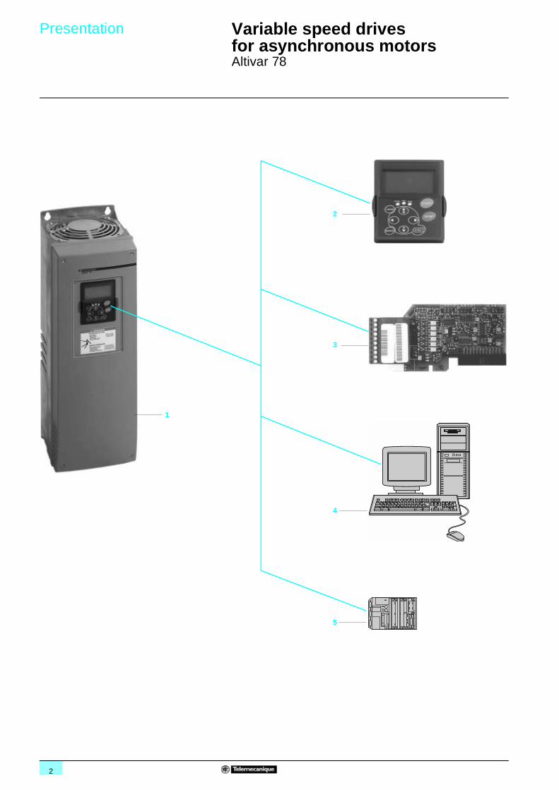
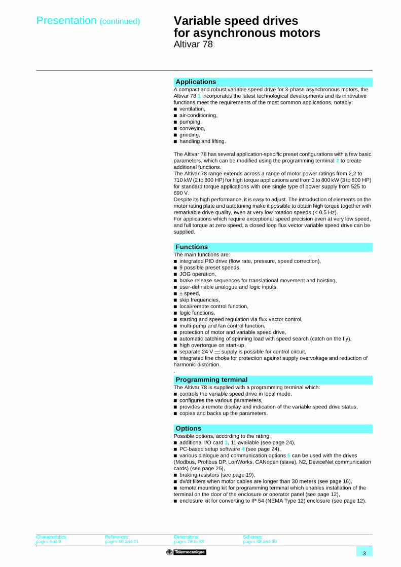
A compact and robust variable speed drive for 3-phase asynchronous motors, the Altivar 78 1 incorporates the latest technological developments and its innovative functions meet the requirements of the most common applications, notably:b ventilation, b air-conditioning,b pumping,b conveying,b grinding,b handling and lifting.
The Altivar 78 has several application-specific preset configurations with a few basic parameters, which can be modified using the programming terminal 2 to create additional functions.The Altivar 78 range extends across a range of motor power ratings from 2,2 to 710 kW (2 to 800 HP) for high torque applications and from 3 to 800 kW (3 to 800 HP) for standard torque applications with one single type of power supply from 525 to 690 V. Despite its high performance, it is easy to adjust. The introduction of elements on the motor rating plate and autotuning make it possible to obtain high torque together with remarkable drive quality, even at very low rotation speeds (< 0.5 Hz).For applications which require exceptional speed precision even at very low speed, and full torque at zero speed, a closed loop flux vector variable speed drive can be supplied.
The main functions are:b integrated PID drive (flow rate, pressure, speed correction),b 9 possible preset speeds,b JOG operation,b brake release sequences for translational movement and hoisting,b user-definable analogue and logic inputs,b ± speed,b skip frequencies,b local/remote control function,b logic functions,b starting and speed regulation via flux vector control,b multi-pump and fan control function,b protection of motor and variable speed drive,b automatic catching of spinning load with speed search (catch on the fly),b high overtorque on start-up,b separate 24 V c supply is possible for control circuit,b integrated line choke for protection against supply overvoltage and reduction of harmonic distortion..
The Altivar 78 is supplied with a programming terminal which:b controls the variable speed drive in local mode,b configures the various parameters,b provides a remote display and indication of the variable speed drive status,b copies and backs up the parameters.
Possible options, according to the rating:b additional I/O card 3, 11 available (see page 24),b PC-based setup software 4 (see page 24),b various dialogue and communication options 5 can be used with the drives (Modbus, Profibus DP, LonWorks, CANopen (slave), N2, DeviceNet communication cards) (see page 25),b braking resistors (see page 19), b dv/dt filters when motor cables are longer than 30 meters (see page 16),b remote mounting kit for programming terminal which enables installation of the terminal on the door of the enclosure or operator panel (see page 12),b enclosure kit for converting to IP 54 (NEMA Type 12) enclosure (see page 12).
Applications
Functions
Programming terminal
Options
Characteristics:pages 6 to 9
References:pages 10 and 11
Dimensions:pages 28 to 33
Schemes:pages 38 and 39
4
Presentation,description 1
Variable speed drives for asynchronous motors 1
Altivar 78Dialogue
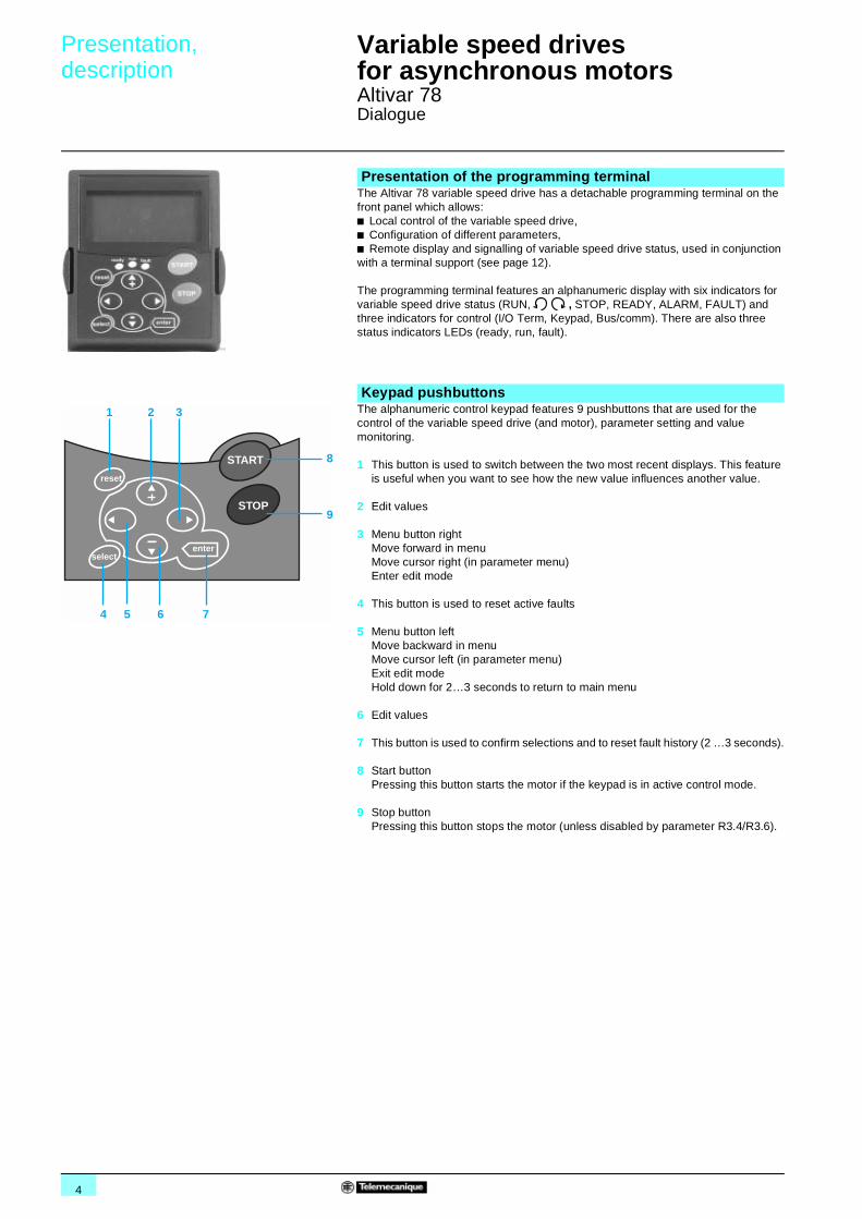
The Altivar 78 variable speed drive has a detachable programming terminal on the front panel which allows:b Local control of the variable speed drive,b Configuration of different parameters,b Remote display and signalling of variable speed drive status, used in conjunction with a terminal support (see page 12).
The programming terminal features an alphanumeric display with six indicators for variable speed drive status (RUN, , STOP, READY, ALARM, FAULT) and three indicators for control (I/O Term, Keypad, Bus/comm). There are also three status indicators LEDs (ready, run, fault).
The alphanumeric control keypad features 9 pushbuttons that are used for the control of the variable speed drive (and motor), parameter setting and value monitoring.
1 This button is used to switch between the two most recent displays. This feature is useful when you want to see how the new value influences another value.
2 Edit values
3 Menu button rightMove forward in menuMove cursor right (in parameter menu)Enter edit mode
4 This button is used to reset active faults
5 Menu button leftMove backward in menuMove cursor left (in parameter menu)Exit edit modeHold down for 2…3 seconds to return to main menu
6 Edit values
7 This button is used to confirm selections and to reset fault history (2 …3 seconds).
8 Start buttonPressing this button starts the motor if the keypad is in active control mode.
9 Stop buttonPressing this button stops the motor (unless disabled by parameter R3.4/R3.6).
Presentation of the programming terminal
Keypad pushbuttons
START
STOP
reset
selectenter
1 2
4 5 6 7
9
8
3
5
Description (continued) 1 Variable speed drives for asynchronous motors 1
Altivar 78Dialogue
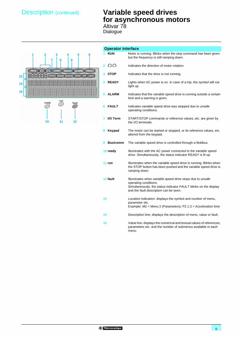
Operator interface1 RUN Motor is running. Blinks when the stop command has been given
but the frequency is still ramping down.
2 Indicates the direction of motor rotation.
3 STOP Indicates that the drive is not running.
4 READY Lights when AC power is on. In case of a trip, the symbol will not light up.
5 ALARM Indicates that the variable speed drive is running outside a certain limit and a warning is given.
6 FAULT Indicates variable speed drive was stopped due to unsafe operating conditions.
7 I/O Term START/STOP commands or reference values, etc. are given by the I/O terminals.
8 Keypad The motor can be started or stopped, or its reference values, etc. altered from the keypad.
9 Bus/comm The variable speed drive is controlled through a fieldbus.
10 ready Illuminates with the AC power connected to the variable speed drive. Simultaneously, the status indicator READY is lit up.
11 run Illuminates when the variable speed drive is running. Blinks when the STOP button has been pushed and the variable speed drive is ramping down.
12 fault Illuminates when variable speed drive stops due to unsafe operating conditions. Simultaneously, the status indicator FAULT blinks on the display and the fault description can be seen.
13 Location indication: displays the symbol and number of menu, parameter etc.Example: M2 = Menu 2 (Parameters); P2.1.3 = Acceleration time
14 Description line: displays the description of menu, value or fault.
15 Value line: displays the numerical and textual values of references, parameters etc. and the number of submenus available in each menu.
Bus/commKeypadI/O Term AutoHand OFF
RUN STOP READY ALARM FAULT
readyrun
fault
1
13
14
15
10 11 12
2
7 8 9
3 4 5 6
6
Characteristics 1 Variable speed drives for asynchronous motors 1
Altivar 78
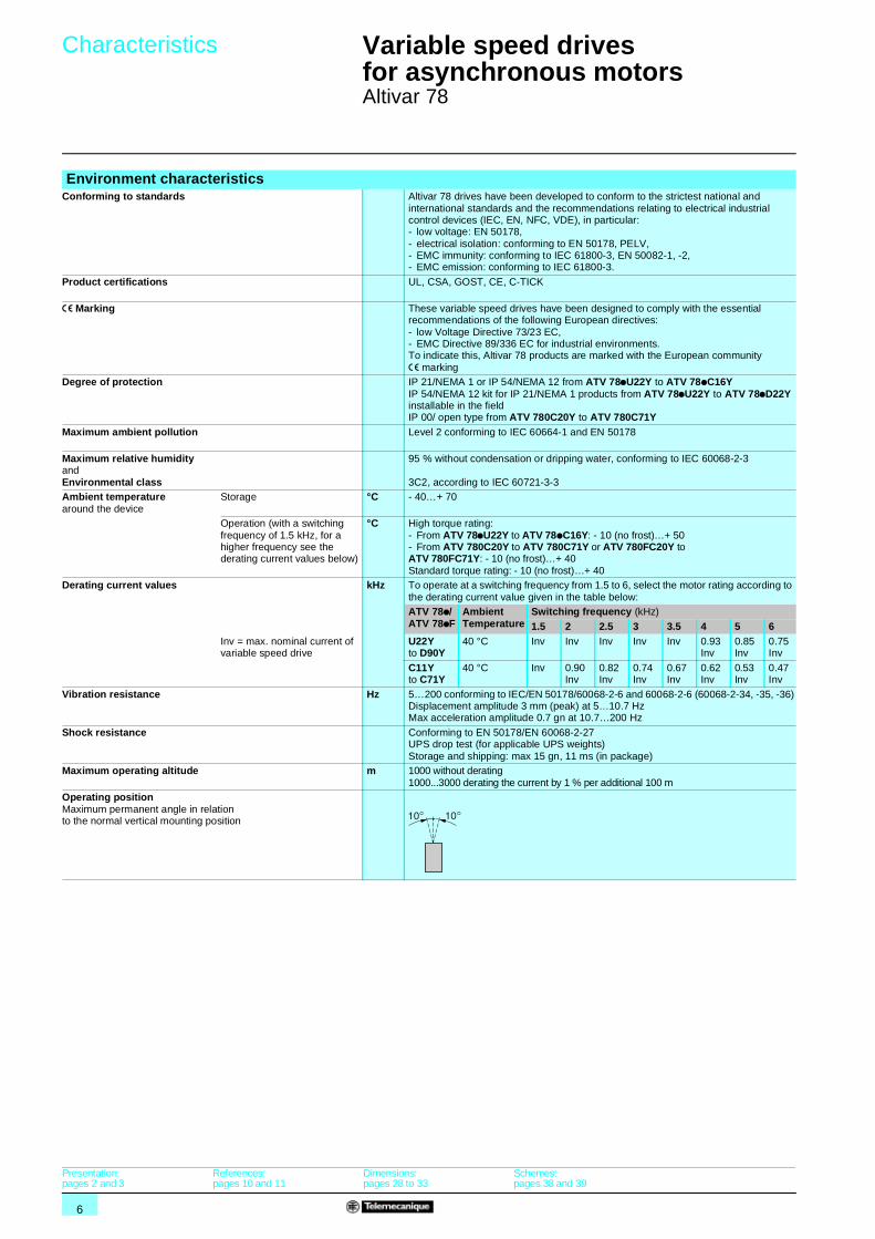
Environment characteristicsConforming to standards Altivar 78 drives have been developed to conform to the strictest national and
international standards and the recommendations relating to electrical industrial control devices (IEC, EN, NFC, VDE), in particular:- low voltage: EN 50178, - electrical isolation: conforming to EN 50178, PELV,- EMC immunity: conforming to IEC 61800-3, EN 50082-1, -2,- EMC emission: conforming to IEC 61800-3.
Product certifications UL, CSA, GOST, CE, C-TICK
e Marking These variable speed drives have been designed to comply with the essential recommendations of the following European directives:- low Voltage Directive 73/23 EC,- EMC Directive 89/336 EC for industrial environments.To indicate this, Altivar 78 products are marked with the European community e marking
Degree of protection IP 21/NEMA 1 or IP 54/NEMA 12 from ATV 78pU22Y to ATV 78pC16YIP 54/NEMA 12 kit for IP 21/NEMA 1 products from ATV 78pU22Y to ATV 78pD22Y installable in the fieldIP 00/ open type from ATV 780C20Y to ATV 780C71Y
Maximum ambient pollution Level 2 conforming to IEC 60664-1 and EN 50178
Maximum relative humidity and Environmental class
95 % without condensation or dripping water, conforming to IEC 60068-2-3
3C2, according to IEC 60721-3-3Ambient temperature around the device
Storage °C - 40…+ 70
Operation (with a switching frequency of 1.5 kHz, for a higher frequency see the derating current values below)
°C High torque rating:- From ATV 78pU22Y to ATV 78pC16Y: - 10 (no frost)…+ 50 - From ATV 780C20Y to ATV 780C71Y or ATV 780FC20Y to ATV 780FC71Y: - 10 (no frost)…+ 40Standard torque rating: - 10 (no frost)…+ 40
Derating current values kHz To operate at a switching frequency from 1.5 to 6, select the motor rating according to the derating current value given in the table below:ATV 78p/ATV 78pF
Ambient Temperature
Switching frequency (kHz)
1.5 2 2.5 3 3.5 4 5 6 Inv = max. nominal current of variable speed drive
U22Y to D90Y
40 °C Inv Inv Inv Inv Inv 0.93 Inv
0.85 Inv
0.75 Inv
C11Y to C71Y
40 °C Inv 0.90 Inv
0.82 Inv
0.74 Inv
0.67 Inv
0.62 Inv
0.53 Inv
0.47 Inv
Vibration resistance Hz 5…200 conforming to IEC/EN 50178/60068-2-6 and 60068-2-6 (60068-2-34, -35, -36)Displacement amplitude 3 mm (peak) at 5…10.7 HzMax acceleration amplitude 0.7 gn at 10.7…200 Hz
Shock resistance Conforming to EN 50178/EN 60068-2-27UPS drop test (for applicable UPS weights)Storage and shipping: max 15 gn, 11 ms (in package)
Maximum operating altitude m 1000 without derating1000...3000 derating the current by 1 % per additional 100 m
Operating position Maximum permanent angle in relation to the normal vertical mounting position
Presentation:pages 2 and 3
References:pages 10 and 11
Dimensions:pages 28 to 33
Schemes:pages 38 and 39

7
Characteristics (continued) 1 Variable speed drives for asynchronous motors 1
Altivar 78
Drive characteristicsOutput frequency range Hz 0…320
Frequency stability: ± 0.01 % at 50 HzResolution: 0.01 Hz
Switching frequency kHz 1.5…6, factory default 1.5Speed range 1…100 in high torque configuration,
1…1000 close loop vector modeSpeed accuracy Without encoder feedback card:
- 30 % of nominal slip, speed > 10 % of nominal motor speed,- 50 % of nominal slip, speed < 5 % of nominal motor speed.
With encoder feedback in control mode: ± 0.01 % of nominal speedTransient overtorque on start-up 200 % of nominal motor torque (typical value ± 10 %) in high torque configuration,
150 % in standard torque configurationMaximum transient current 525...690 V: 150 % of nominal current in high torque operation for 60 s then 100 % in
continuous operation110 % of nominal current in standard torque operation (variable torque) for 60 s then 100 % in continuous operation
Braking torque Up to 30 % of nominal motor torque without braking unit (typical value)Up to 100 % with external brake resistor
Control method ATV 78ppppY: flux vector control without sensor; constant torque or variable torque.ATV 78pFpppY: flux vector control with sensor for more accurate speed control and torque control
Electrical characteristics3-phase power supply Voltage V 525…690 V, ± 10 %
Frequency Hz 45…66
Output voltage Maximum voltage equal to line supply voltage
Efficiency 97.5 % (including line choke losses), at 50/60 Hz at nominal load
Available internal supplies 1 + 10 V output 0..+ 3 %, 10 mA maximum, with short-circuit protection1 + 24 V output ± 15 %, 150 mA maximum with short-circuit protection
Analogue inputs AI1 1 analogue voltage input 0…10 V Impedance 200 kΩPrecision ± 1 % of full scale (10 V)10-bit resolution
AI2 1 analogue current input: 0 (4)…20 mA differentialMaximum load: 250 Ω10-bit resolution
Analogue output AO Analogue current output 0 (4)…20 mA with programmable operationsMaximum external load < 500 Ω10-bit resolution, accuracy ± 3 %
Logic inputs DIp 6 bipolar inputs: positive or negative logic, c 18… 30 VProgrammable operations, impedance > 5 kΩState 1 above 18 V, state 0 below 10 V
Auxiliary power supply Used to supply the control circuit and option cards via an external + 24 V if the main power supply is cut.+ 24 V input ± 15 %, 300 mA minimumSeparated from the internal power supply by a diode
Output relay Programmable relaySwitching voltage: c 24 V/6 A, a 250 V/6 A, c 125 V/0.4 AMax. continuous current < 2 A RMSMin. switched current 5 V/ 10 mAElectrical isolation between the line supply and the relay power supply
Signalling Via 3 indicator lamps on the programming terminal,- green power on,- green drive running,- red drive fault.
Presentation:pages 2 and 3
References:pages 10 and 11
Dimensions:pages 28 to 33
Schemes:pages 38 and 39
8
Characteristics (continued) 1 Variable speed drives for asynchronous motors 1
Altivar 78
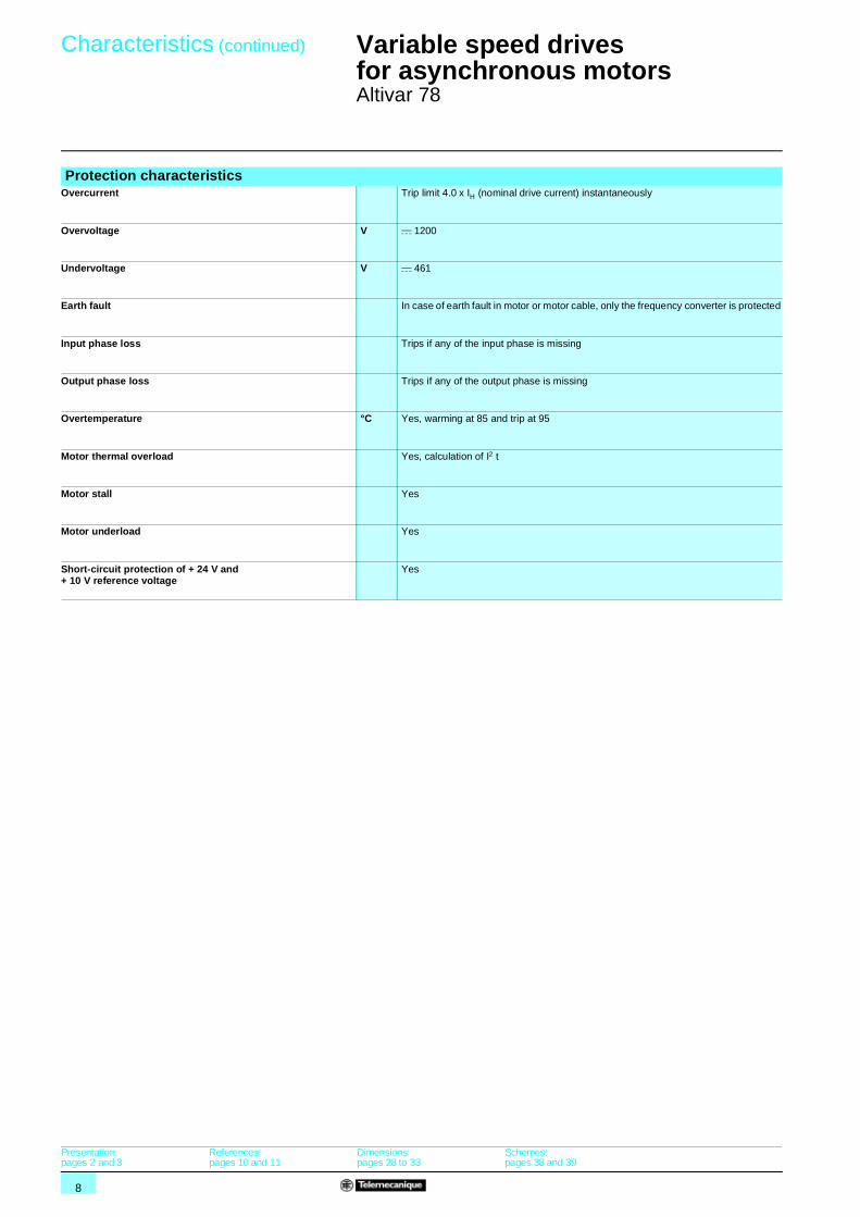
Protection characteristicsOvercurrent Trip limit 4.0 x IH (nominal drive current) instantaneously
Overvoltage V c 1200
Undervoltage V c 461
Earth fault In case of earth fault in motor or motor cable, only the frequency converter is protected
Input phase loss Trips if any of the input phase is missing
Output phase loss Trips if any of the output phase is missing
Overtemperature °C Yes, warming at 85 and trip at 95
Motor thermal overload Yes, calculation of I2 t
Motor stall Yes
Motor underload Yes
Short-circuit protection of + 24 V and + 10 V reference voltage
Yes
Presentation:pages 2 and 3
References:pages 10 and 11
Dimensions:pages 28 to 33
Schemes:pages 38 and 39
9
Characteristics (continued)
Operation 1
Variable speed drives for asynchronous motors 1
Altivar 78
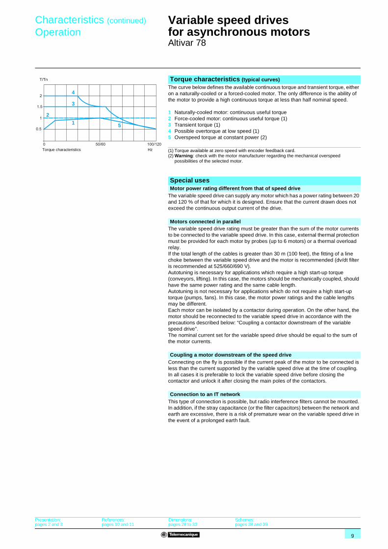
Torque characteristics (typical curves)The curve below defines the available continuous torque and transient torque, either on a naturally-cooled or a forced-cooled motor. The only difference is the ability of the motor to provide a high continuous torque at less than half nominal speed.
1 Naturally-cooled motor: continuous useful torque2 Force-cooled motor: continuous useful torque (1)3 Transient torque (1)4 Possible overtorque at low speed (1)5 Overspeed torque at constant power (2)
(1) Torque available at zero speed with encoder feedback card.(2) Warning: check with the motor manufacturer regarding the mechanical overspeed
possibilities of the selected motor.
Special usesMotor power rating different from that of speed drive
The variable speed drive can supply any motor which has a power rating between 20 and 120 % of that for which it is designed. Ensure that the current drawn does not exceed the continuous output current of the drive.
Motors connected in parallelThe variable speed drive rating must be greater than the sum of the motor currents to be connected to the variable speed drive. In this case, external thermal protection must be provided for each motor by probes (up to 6 motors) or a thermal overload relay.If the total length of the cables is greater than 30 m (100 feet), the fitting of a line choke between the variable speed drive and the motor is recommended (dv/dt filter is recommended at 525/660/690 V).Autotuning is necessary for applications which require a high start-up torque (conveyors, lifting). In this case, the motors should be mechanically coupled, should have the same power rating and the same cable length.Autotuning is not necessary for applications which do not require a high start-up torque (pumps, fans). In this case, the motor power ratings and the cable lengths may be different.Each motor can be isolated by a contactor during operation. On the other hand, the motor should be reconnected to the variable speed drive in accordance with the precautions described below: “Coupling a contactor downstream of the variable speed drive”.The nominal current set for the variable speed drive should be equal to the sum of the motor currents.
Coupling a motor downstream of the speed driveConnecting on the fly is possible if the current peak of the motor to be connected is less than the current supported by the variable speed drive at the time of coupling.In all cases it is preferable to lock the variable speed drive before closing the contactor and unlock it after closing the main poles of the contactors.
Connection to an IT networkThis type of connection is possible, but radio interference filters cannot be mounted. In addition, if the stray capacitance (or the filter capacitors) between the network and earth are excessive, there is a risk of premature wear on the variable speed drive in the event of a prolonged earth fault.
1
3
4
2
5
T/Tn
Torque characteristics Hz
Presentation:pages 2 and 3
References:pages 10 and 11
Dimensions:pages 28 to 33
Schemes:pages 38 and 39
10
References 1 Variable speed drives for asynchronous motors 1
Altivar 78
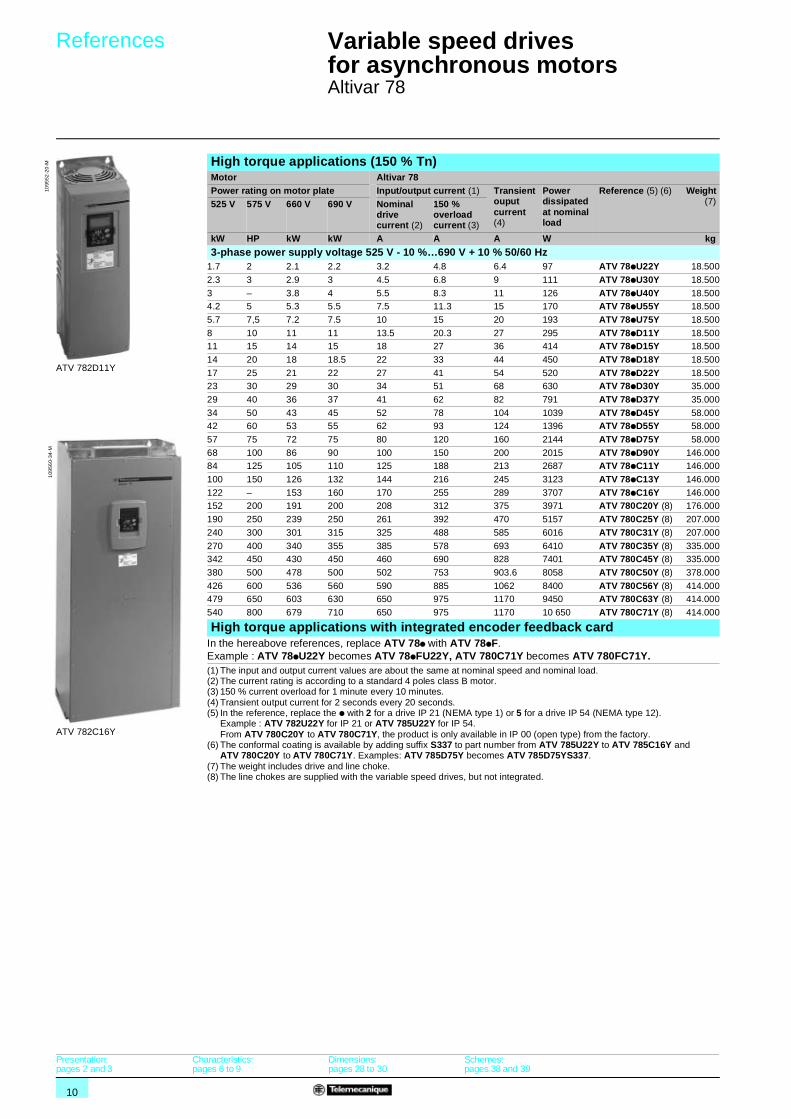
High torque applications (150 % Tn)Motor Altivar 78Power rating on motor plate Input/output current (1) Transient
ouput current(4)
Power dissipated at nominal load
Reference (5) (6) Weight(7)525 V 575 V 660 V 690 V Nominal
drive current (2)
150 % overload current (3)
kW HP kW kW A A A W kg
3-phase power supply voltage 525 V - 10 %…690 V + 10 % 50/60 Hz1.7 2 2.1 2.2 3.2 4.8 6.4 97 ATV 78pU22Y 18.500
2.3 3 2.9 3 4.5 6.8 9 111 ATV 78pU30Y 18.500
3 – 3.8 4 5.5 8.3 11 126 ATV 78pU40Y 18.5004.2 5 5.3 5.5 7.5 11.3 15 170 ATV 78pU55Y 18.500
5.7 7,5 7.2 7.5 10 15 20 193 ATV 78pU75Y 18.500
8 10 11 11 13.5 20.3 27 295 ATV 78pD11Y 18.50011 15 14 15 18 27 36 414 ATV 78pD15Y 18.500
14 20 18 18.5 22 33 44 450 ATV 78pD18Y 18.500
17 25 21 22 27 41 54 520 ATV 78pD22Y 18.50023 30 29 30 34 51 68 630 ATV 78pD30Y 35.000
29 40 36 37 41 62 82 791 ATV 78pD37Y 35.000
34 50 43 45 52 78 104 1039 ATV 78pD45Y 58.00042 60 53 55 62 93 124 1396 ATV 78pD55Y 58.000
57 75 72 75 80 120 160 2144 ATV 78pD75Y 58.000
68 100 86 90 100 150 200 2015 ATV 78pD90Y 146.00084 125 105 110 125 188 213 2687 ATV 78pC11Y 146.000
100 150 126 132 144 216 245 3123 ATV 78pC13Y 146.000
122 – 153 160 170 255 289 3707 ATV 78pC16Y 146.000152 200 191 200 208 312 375 3971 ATV 780C20Y (8) 176.000
190 250 239 250 261 392 470 5157 ATV 780C25Y (8) 207.000
240 300 301 315 325 488 585 6016 ATV 780C31Y (8) 207.000
270 400 340 355 385 578 693 6410 ATV 780C35Y (8) 335.000342 450 430 450 460 690 828 7401 ATV 780C45Y (8) 335.000
380 500 478 500 502 753 903.6 8058 ATV 780C50Y (8) 378.000
426 600 536 560 590 885 1062 8400 ATV 780C56Y (8) 414.000479 650 603 630 650 975 1170 9450 ATV 780C63Y (8) 414.000
540 800 679 710 650 975 1170 10 650 ATV 780C71Y (8) 414.000
High torque applications with integrated encoder feedback cardIn the hereabove references, replace ATV 78p with ATV 78pF. Example : ATV 78pU22Y becomes ATV 78pFU22Y, ATV 780C71Y becomes ATV 780FC71Y.(1) The input and output current values are about the same at nominal speed and nominal load.(2) The current rating is according to a standard 4 poles class B motor.(3) 150 % current overload for 1 minute every 10 minutes.(4) Transient output current for 2 seconds every 20 seconds.(5) In the reference, replace the p with 2 for a drive IP 21 (NEMA type 1) or 5 for a drive IP 54 (NEMA type 12).
Example : ATV 782U22Y for IP 21 or ATV 785U22Y for IP 54.From ATV 780C20Y to ATV 780C71Y, the product is only available in IP 00 (open type) from the factory.
(6) The conformal coating is available by adding suffix S337 to part number from ATV 785U22Y to ATV 785C16Y and ATV 780C20Y to ATV 780C71Y. Examples: ATV 785D75Y becomes ATV 785D75YS337.
(7) The weight includes drive and line choke.(8) The line chokes are supplied with the variable speed drives, but not integrated.
ATV 782D11Y
1095
52-2
0-M
ATV 782C16Y
109
560-
34-M
Presentation:pages 2 and 3
Characteristics:pages 6 to 9
Dimensions:pages 28 to 30
Schemes:pages 38 and 39
11
References (continued) 1 Variable speed drives for asynchronous motors 1
Altivar 78
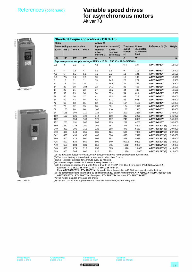
Standard torque applications (110 % Tn)Motor Altivar 78Power rating on motor plate Input/output current (1) Transient
ouput current(4)
Power dissipated at nominal load
Reference (5) (6) Weight(7)525 V 575 V 660 V 690 V Nominal
drive current (2)
110 % overload current (3)
kW HP kW kW A A A W kg
3-phase power supply voltage 525 V - 10 %…690 V + 10 % 50/60 Hz2.3 3 2.9 3 4.5 5 6.4 104 ATV 78pU22Y 18.500
3 – 3.8 4 5.5 6.1 9 118 ATV 78pU30Y 18.500
4.2 5 5.3 5.5 7.5 8.3 11 141 ATV 78pU40Y 18.500
5.7 7.5 7.2 7.5 10 11 15 190 ATV 78pU55Y 18.5008 10 11 11 13 14.9 20 227 ATV 78pU75Y 18.500
11 15 14 15 18 19.8 27 342 ATV 78pD11Y 18.500
14 20 18 18.5 22 24.2 36 455 ATV 78pD15Y 18.50017 25 21 22 27 29.7 44 483 ATV 78pD18Y 18.500
23 30 29 30 34 37.4 54 614 ATV 78pD22Y 18.500
29 40 36 37 41 45.1 68 712 ATV 78pD30Y 35.00034 50 43 45 52 57.2 82 901 ATV 78pD37Y 35.000
42 60 53 55 62 68.2 104 1160 ATV 78pD45Y 58.000
57 75 72 75 80 88 124 1670 ATV 78pD55Y 58.00068 100 86 90 100 110 160 2345 ATV 78pD75Y 58.000
84 125 105 110 125 138 200 2286 ATV 78pD90Y 146.000
100 150 126 132 144 158 213 2998 ATV 78pC11Y 146.000122 – 153 160 170 187 245 3639 ATV 78pC13Y 146.000
152 200 191 200 208 229 289 4263 ATV 78pC16Y 146.000
190 250 239 250 261 287 375 4803 ATV 780C20Y (8) 176.000240 300 301 315 325 358 470 5660 ATV 780C25Y (8) 207.000
270 400 340 355 385 424 585 7089 ATV 780C31Y (8) 207.000
342 450 430 450 460 506 693 7377 ATV 780C35Y (8) 335.000
380 500 478 500 502 552 828 8635 ATV 780C45Y (8) 335.000426 600 536 560 590 649 903.6 9201 ATV 780C50Y (8) 378.000
479 650 603 630 650 715 1062 9450 ATV 780C56Y (8) 414.000
540 800 679 710 650 825 1170 10 650 ATV 780C63Y (8) 414.000609 800 765 800 820 902 1170 12 000 ATV 780C71Y (8) 414.000
(1) The input and output current values are about the same at nominal speed and nominal load.(2) The current rating is according to a standard 4 poles class B motor.(3) 150 % current overload for 1 minute every 10 minutes.(4) Transient output current for 2 seconds every 20 seconds.(5) In the reference, replace the p with 2 for a drive IP 21 (NEMA type 1) or 5 for a drive IP 54 (NEMA type 12).
Example : ATV 782U22Y for IP 21 or ATV 785U22Y for IP 54.From ATV 780C20Y to ATV 780C71Y, the product is only available in IP 00 (open type) from the factory.
(6) The conformal coating is available by adding suffix S337 to part number from ATV 785U22Y to ATV 785C16Y and ATV 780C20Y to ATV 780C71Y. Examples: ATV 785D75Y becomes ATV 785D75YS337.
(7) The weight includes drive and line choke.(8) The line chokes are supplied with the variable speed drives, but not integrated.
ATV 782D11Y
1095
52-2
0-M
ATV 782C16Y
1095
60-3
4-M
Presentation:pages 2 and 3
Characteristics:pages 6 to 9
Dimensions:pages 28 to 30
Schemes:pages 38 and 39

12
References 1 Variable speed drives for asynchronous motors 1
Altivar 78Accessories
Programming terminal remote mounting kitThe Altivar 78 is supplied with a detachable programming terminal (see page 4).
A terminal support option allows remote mounting of the programming terminal at a distance of 2 or 15 metres. It is particularly suitable for mounting on the enclosure door.
The programming terminal remote mounting kit includes:b terminal support,b connection cable (2 or 15 m lengths),b screws and washers.
Description Cable lengthm
For drives Reference Weightkg
Terminal support 2 ATV 78 all ratings VW3 A78102 1.000
15 ATV 78 all ratings VW3 A78103 1.000
PC-based setup software ATV 78 SoftThe PC software is provided in a CD-ROM, shipped with the product.
The PC connection kit allows the connection between the PC operating in a Microsoft Windows® environment.
Minimum PC configuration: Pentium 3 processor with 128 Mb of RAM.Operating system: Windows® 95, 98, NT, 2000 or XP.
Main functions:b drive configuration,b configuration backup,b print out of complete parameter list,b parameters comparison,b load a configuration from one drive to another,b oscilloscope mode for maintenance,b control and monitoring.
Description Cable lengthm
For drives Reference Weightkg
PC cable 1.5 ATV 78 all ratings VW3 A78332 0.300
IP 54 kit (NEMA Type 12)The IP 54 kit enhances the enclosure IP 21 protection class of the variable speed drive to IP 54 protection class. The IP 54 enclosure provides protection against dust and water sprayed from all directions. However, it does not protect the variable speed drive against strong jets of water or if it is immersed.
The IP 54 kit includes:b IP 54 enclosure,b IP 54 lid with fan,b cable entry flange with rubber grommets,b rubber sealings,b screws, cable anchors, fastening straps, warning sticker.
Description For drives Reference Weightkg
IP 54 kit ATV 782U22Y...2D22YATV 782FU22Y...2FD22Y
VW3 A78801 1.500
VW3 A7810p
DF
565
076
Dimensions:page 30
13
References 1 Variable speed drives for asynchronous motors 1
Altivar 78Accessories
Flange mounting kitTo reduce power dissipated in the enclosure, the Altivar 78 variable speed drive IP 20/NEMA type 1 from 2.2 to 160 kW (2 to 150 HP) may be flange mounted in a wall of the enclosure with the heatsink on the outside. This requires a cutout in the enclosure and a flange mounting kit.
For flange mounting, the heatsink and fan on the outside of the enclosure are IP 54/NEMA type 12 degree of protection.
The flange mounting kit includes:b gaskets,b top and bottom flange,b fan,b sealing tape,b cable tie, screws,b instructions and cutout dimensions.
For drives Reference Weightkg
ATV 782U22Y…2D22YATV 782FU22Y…2FD22Y
VW3 A78806 0.370
ATV 782D30Y and 2D37YATV 782FD30Y and 2FD37Y
VW3 A78807 2.000
ATV 782D45Y…2D75YATV 782FD45Y…2FD75Y
VW3 A78808 3.000
ATV 782D90Y…2C16YATV 782FD90Y…2FC16Y
VW3 A78809 8.500
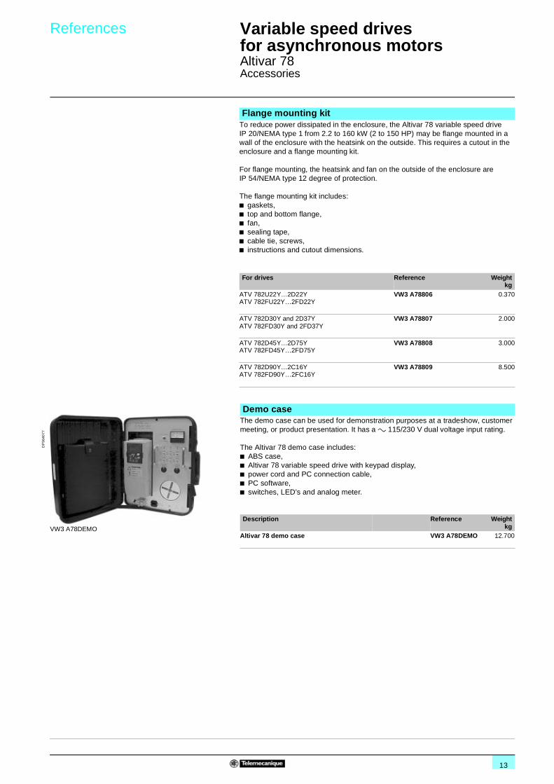
Demo caseThe demo case can be used for demonstration purposes at a tradeshow, customer meeting, or product presentation. It has a a 115/230 V dual voltage input rating.
The Altivar 78 demo case includes:b ABS case,b Altivar 78 variable speed drive with keypad display,b power cord and PC connection cable,b PC software,b switches, LED’s and analog meter.
Description Reference Weightkg
Altivar 78 demo case VW3 A78DEMO 12.700VW3 A78DEMO
DF
5640
77
14
Presentation 1 Variable speed drives for asynchronous motors 1
Altivar 78Reduction of harmonic currents
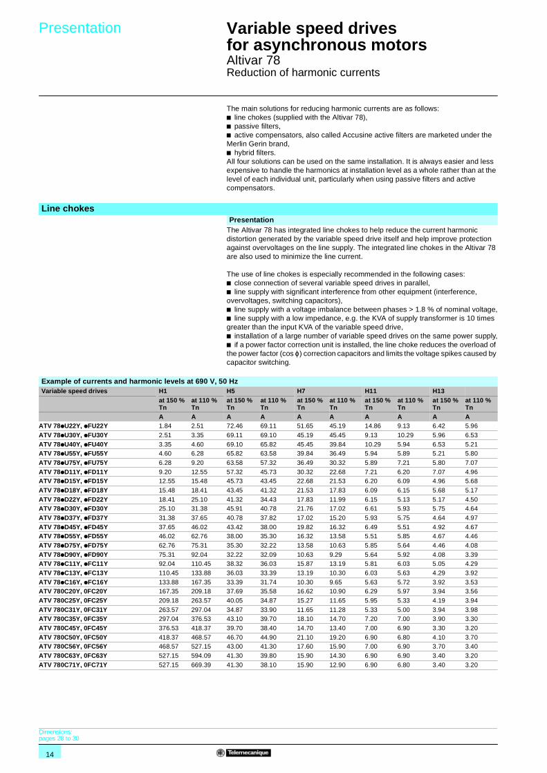
The main solutions for reducing harmonic currents are as follows:b line chokes (supplied with the Altivar 78),b passive filters,b active compensators, also called Accusine active filters are marketed under the Merlin Gerin brand,b hybrid filters. All four solutions can be used on the same installation. It is always easier and less expensive to handle the harmonics at installation level as a whole rather than at the level of each individual unit, particularly when using passive filters and active compensators.
Line chokesPresentation
The Altivar 78 has integrated line chokes to help reduce the current harmonic distortion generated by the variable speed drive itself and help improve protection against overvoltages on the line supply. The integrated line chokes in the Altivar 78 are also used to minimize the line current.
The use of line chokes is especially recommended in the following cases:b close connection of several variable speed drives in parallel,b line supply with significant interference from other equipment (interference, overvoltages, switching capacitors),b line supply with a voltage imbalance between phases > 1.8 % of nominal voltage,b line supply with a low impedance, e.g. the KVA of supply transformer is 10 times greater than the input KVA of the variable speed drive,b installation of a large number of variable speed drives on the same power supply,b if a power factor correction unit is installed, the line choke reduces the overload of the power factor (cos ϕ) correction capacitors and limits the voltage spikes caused by capacitor switching.
Example of currents and harmonic levels at 690 V, 50 HzVariable speed drives H1 H5 H7 H11 H13
at 150 % Tn
at 110 % Tn
at 150 % Tn
at 110 % Tn
at 150 % Tn
at 110 % Tn
at 150 % Tn
at 110 % Tn
at 150 % Tn
at 110 % Tn
A A A A A A A A A AATV 78pU22Y, pFU22Y 1.84 2.51 72.46 69.11 51.65 45.19 14.86 9.13 6.42 5.96
ATV 78pU30Y, pFU30Y 2.51 3.35 69.11 69.10 45.19 45.45 9.13 10.29 5.96 6.53
ATV 78pU40Y, pFU40Y 3.35 4.60 69.10 65.82 45.45 39.84 10.29 5.94 6.53 5.21ATV 78pU55Y, pFU55Y 4.60 6.28 65.82 63.58 39.84 36.49 5.94 5.89 5.21 5.80
ATV 78pU75Y, pFU75Y 6.28 9.20 63.58 57.32 36.49 30.32 5.89 7.21 5.80 7.07
ATV 78pD11Y, pFD11Y 9.20 12.55 57.32 45.73 30.32 22.68 7.21 6.20 7.07 4.96ATV 78pD15Y, pFD15Y 12.55 15.48 45.73 43.45 22.68 21.53 6.20 6.09 4.96 5.68
ATV 78pD18Y, pFD18Y 15.48 18.41 43.45 41.32 21.53 17.83 6.09 6.15 5.68 5.17
ATV 78pD22Y, pFD22Y 18.41 25.10 41.32 34.43 17.83 11.99 6.15 5.13 5.17 4.50ATV 78pD30Y, pFD30Y 25.10 31.38 45.91 40.78 21.76 17.02 6.61 5.93 5.75 4.64
ATV 78pD37Y, pFD37Y 31.38 37.65 40.78 37.82 17.02 15.20 5.93 5.75 4.64 4.97
ATV 78pD45Y, pFD45Y 37.65 46.02 43.42 38.00 19.82 16.32 6.49 5.51 4.92 4.67ATV 78pD55Y, pFD55Y 46.02 62.76 38.00 35.30 16.32 13.58 5.51 5.85 4.67 4.46
ATV 78pD75Y, pFD75Y 62.76 75.31 35.30 32.22 13.58 10.63 5.85 5.64 4.46 4.08
ATV 78pD90Y, pFD90Y 75.31 92.04 32.22 32.09 10.63 9.29 5.64 5.92 4.08 3.39ATV 78pC11Y, pFC11Y 92.04 110.45 38.32 36.03 15.87 13.19 5.81 6.03 5.05 4.29
ATV 78pC13Y, pFC13Y 110.45 133.88 36.03 33.39 13.19 10.30 6.03 5.63 4.29 3.92
ATV 78pC16Y, pFC16Y 133.88 167.35 33.39 31.74 10.30 9.65 5.63 5.72 3.92 3.53ATV 780C20Y, 0FC20Y 167.35 209.18 37.69 35.58 16.62 10.90 6.29 5.97 3.94 3.56
ATV 780C25Y, 0FC25Y 209.18 263.57 40.05 34.87 15.27 11.65 5.95 5.33 4.19 3.94
ATV 780C31Y, 0FC31Y 263.57 297.04 34.87 33.90 11.65 11.28 5.33 5.00 3.94 3.98ATV 780C35Y, 0FC35Y 297.04 376.53 43.10 39.70 18.10 14.70 7.20 7.00 3.90 3.30
ATV 780C45Y, 0FC45Y 376.53 418.37 39.70 38.40 14.70 13.40 7.00 6.90 3.30 3.20
ATV 780C50Y, 0FC50Y 418.37 468.57 46.70 44.90 21.10 19.20 6.90 6.80 4.10 3.70ATV 780C56Y, 0FC56Y 468.57 527.15 43.00 41.30 17.60 15.90 7.00 6.90 3.70 3.40
ATV 780C63Y, 0FC63Y 527.15 594.09 41.30 39.80 15.90 14.30 6.90 6.90 3.40 3.20
ATV 780C71Y, 0FC71Y 527.15 669.39 41.30 38.10 15.90 12.90 6.90 6.80 3.40 3.20
Dimensions:pages 28 to 30
15
Characteristics,presentation 1
Variable speed drives for asynchronous motors 1
Altivar 78Reduction of harmonic currents
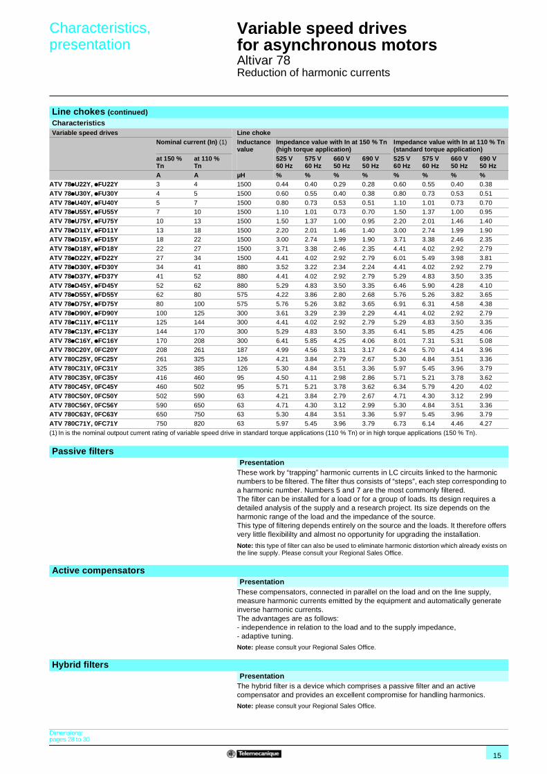
Line chokes (continued)CharacteristicsVariable speed drives Line choke
Nominal current (In) (1) Inductance value
Impedance value with In at 150 % Tn(high torque application)
Impedance value with In at 110 % Tn (standard torque application)
at 150 % Tn
at 110 % Tn
525 V60 Hz
575 V60 Hz
660 V50 Hz
690 V50 Hz
525 V60 Hz
575 V60 Hz
660 V50 Hz
690 V50 Hz
A A µH % % % % % % % %ATV 78pU22Y, pFU22Y 3 4 1500 0.44 0.40 0.29 0.28 0.60 0.55 0.40 0.38
ATV 78pU30Y, pFU30Y 4 5 1500 0.60 0.55 0.40 0.38 0.80 0.73 0.53 0.51
ATV 78pU40Y, pFU40Y 5 7 1500 0.80 0.73 0.53 0.51 1.10 1.01 0.73 0.70ATV 78pU55Y, pFU55Y 7 10 1500 1.10 1.01 0.73 0.70 1.50 1.37 1.00 0.95
ATV 78pU75Y, pFU75Y 10 13 1500 1.50 1.37 1.00 0.95 2.20 2.01 1.46 1.40
ATV 78pD11Y, pFD11Y 13 18 1500 2.20 2.01 1.46 1.40 3.00 2.74 1.99 1.90ATV 78pD15Y, pFD15Y 18 22 1500 3.00 2.74 1.99 1.90 3.71 3.38 2.46 2.35
ATV 78pD18Y, pFD18Y 22 27 1500 3.71 3.38 2.46 2.35 4.41 4.02 2.92 2.79
ATV 78pD22Y, pFD22Y 27 34 1500 4.41 4.02 2.92 2.79 6.01 5.49 3.98 3.81ATV 78pD30Y, pFD30Y 34 41 880 3.52 3.22 2.34 2.24 4.41 4.02 2.92 2.79
ATV 78pD37Y, pFD37Y 41 52 880 4.41 4.02 2.92 2.79 5.29 4.83 3.50 3.35
ATV 78pD45Y, pFD45Y 52 62 880 5.29 4.83 3.50 3.35 6.46 5.90 4.28 4.10ATV 78pD55Y, pFD55Y 62 80 575 4.22 3.86 2.80 2.68 5.76 5.26 3.82 3.65
ATV 78pD75Y, pFD75Y 80 100 575 5.76 5.26 3.82 3.65 6.91 6.31 4.58 4.38
ATV 78pD90Y, pFD90Y 100 125 300 3.61 3.29 2.39 2.29 4.41 4.02 2.92 2.79ATV 78pC11Y, pFC11Y 125 144 300 4.41 4.02 2.92 2.79 5.29 4.83 3.50 3.35
ATV 78pC13Y, pFC13Y 144 170 300 5.29 4.83 3.50 3.35 6.41 5.85 4.25 4.06
ATV 78pC16Y, pFC16Y 170 208 300 6.41 5.85 4.25 4.06 8.01 7.31 5.31 5.08ATV 780C20Y, 0FC20Y 208 261 187 4.99 4.56 3.31 3.17 6.24 5.70 4.14 3.96
ATV 780C25Y, 0FC25Y 261 325 126 4.21 3.84 2.79 2.67 5.30 4.84 3.51 3.36
ATV 780C31Y, 0FC31Y 325 385 126 5.30 4.84 3.51 3.36 5.97 5.45 3.96 3.79
ATV 780C35Y, 0FC35Y 416 460 95 4.50 4.11 2.98 2.86 5.71 5.21 3.78 3.62ATV 780C45Y, 0FC45Y 460 502 95 5.71 5.21 3.78 3.62 6.34 5.79 4.20 4.02
ATV 780C50Y, 0FC50Y 502 590 63 4.21 3.84 2.79 2.67 4.71 4.30 3.12 2.99
ATV 780C56Y, 0FC56Y 590 650 63 4.71 4.30 3.12 2.99 5.30 4.84 3.51 3.36ATV 780C63Y, 0FC63Y 650 750 63 5.30 4.84 3.51 3.36 5.97 5.45 3.96 3.79
ATV 780C71Y, 0FC71Y 750 820 63 5.97 5.45 3.96 3.79 6.73 6.14 4.46 4.27
(1) In is the nominal outpout current rating of variable speed drive in standard torque applications (110 % Tn) or in high torque applications (150 % Tn).
Passive filtersPresentation
These work by “trapping” harmonic currents in LC circuits linked to the harmonic numbers to be filtered. The filter thus consists of “steps”, each step corresponding to a harmonic number. Numbers 5 and 7 are the most commonly filtered. The filter can be installed for a load or for a group of loads. Its design requires a detailed analysis of the supply and a research project. Its size depends on the harmonic range of the load and the impedance of the source. This type of filtering depends entirely on the source and the loads. It therefore offers very little flexibililty and almost no opportunity for upgrading the installation.
Note: this type of filter can also be used to eliminate harmonic distortion which already exists on the line supply. Please consult your Regional Sales Office.
Active compensatorsPresentation
These compensators, connected in parallel on the load and on the line supply, measure harmonic currents emitted by the equipment and automatically generate inverse harmonic currents.The advantages are as follows: - independence in relation to the load and to the supply impedance,- adaptive tuning.
Note: please consult your Regional Sales Office.
Hybrid filtersPresentation
The hybrid filter is a device which comprises a passive filter and an active compensator and provides an excellent compromise for handling harmonics.
Note: please consult your Regional Sales Office.
Dimensions:pages 28 to 30
16
Presentation,references 1
Variable speed drives for asynchronous motors 1
Altivar 78Options: dv/dt long lead filters
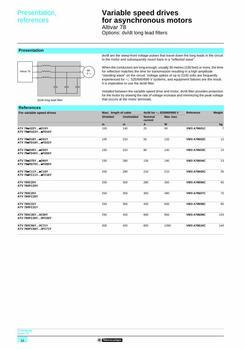
Presentation dv/dt are the steep-front voltage pulses that travel down the long leads in the circuit
to the motor and subsequently revert back in a “reflected wave”.
When the conductors are long enough, usually 30 metres (100 feet) or more, the time for reflection matches the time for transmission resulting in a high amplitude “standing wave” on the circuit. Voltage spikes of up to 2100 volts are frequently experienced for a 525/660/690 V systems, and equipment failures are the result. It is imperative to use the dv/dt filter.
Installed between the variable speed drive and motor, dv/dt filter provides protection for the motor by slowing the rate of voltage increase and minimizing the peak voltage that occurs at the motor terminals.
ReferencesFor variable speed drives Maxi. length of cable dv/dt for a 525/660/690 V Reference Weight
Shielded Unshielded Nominal current
Max. loss
m m A W kgATV 78pU22Y…pD15YATV 78pFU22Y…pFD15Y
100 140 25 90 VW3 A78601C 7
ATV 78pD18Y…pD31YATV 78pFD18Y…pFD31Y
100 210 55 120 VW3 A78602C 12
ATV 78pD45Y…pD55YATV 78pFD45Y…pFD55Y
150 210 80 140 VW3 A78603C 15
ATV 78pD75Y…pD90YATV 78pFD75Y…pFD90Y
150 280 130 190 VW3 A78604C 23
ATV 78pC11Y…pC16YATV 78pFC11Y…pFC16Y
200 280 210 210 VW3 A78605C 35
ATV 780C20YATV 780FC20Y
200 350 280 350 VW3 A78606C 60
ATV 780C25YATV 780FC25Y
250 350 350 480 VW3 A78607C 70
ATV 780C31YATV 780FC31Y
250 350 420 650 VW3 A78608C 85
ATV 780C35Y…0C50YATV 780FC35Y…0FC50Y
250 420 600 850 VW3 A78609C 120
ATV 780C56Y…0C71YATV 780FC56Y…0FC71Y
300 420 820 1050 VW3 A78610C 140
Altivar 78
dv/dt long lead filter
Dimensions:pages 31
17
Presentation 1 Variable speed drives for asynchronous motors 1
Altivar 78Options: output chokes
Presentation The use of an output chokes between the drive and the motor is recommended for motor cables which are longer than 10 metres (30 feet). This makes it possible to:b limit dv/dt,b limit overvoltage on the motor terminal,b limit “reflected wave” from the motor back to the variable speed drive,b filter interference caused by opening a contactor placed between the reactor and the motor,b reduce the motor earth leakage current.
Note: please consult your Regional Sales Office.
18
Presentation, characteristics 1
Variable speed drives for asynchronous motors 1
Altivar 78Options: braking resistors
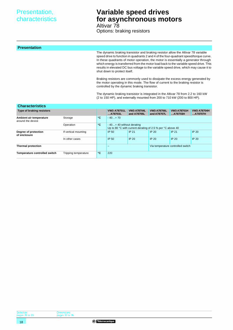
PresentationThe dynamic braking transistor and braking resistor allow the Altivar 78 variable speed drive to function in quadrants 2 and 4 of the four-quadrant speed/torque curve. In these quadrants of motor operation, the motor is essentially a generator through which energy is transferred from the motor load back to the variable speed drive. This results in elevated DC bus voltage to the variable speed drive, which may cause it to shut down to protect itself.
Braking resistors are commonly used to dissipate the excess energy generated by the motor operating in this mode. The flow of current to the braking resistor is controlled by the dynamic braking transistor.
The dynamic braking transistor is integrated in the Altivar 78 from 2.2 to 160 kW (2 to 150 HP), and externally mounted from 200 to 710 kW (200 to 800 HP).
CharacteristicsType of braking resistors VW3 A78701L
…A78703LVW3 A78704L and A78705L
VW3 A78706L and A78707L
VW3 A78701H…A78703H
VW3 A78704H…A78707H
Ambient air temperature around the device
Storage °C - 40…+ 70
Operation °C - 40…+ 40 without deratingUp to 80 °C with current derating of 2.5 % per °C above 40
Degree of protection of enclosure
If vertical mounting IP 50 IP 21 IP 20 IP 21 IP 20
In other cases IP 50 IP 20 IP 20 IP 20 IP 20
Thermal protection – Via temperature controlled switch
Temperature controlled switch Tripping temperature °C 220
Selection:pages 20 to 23
Dimensions:pages 32 to 35
19
References 1 Variable speed drives for asynchronous motors 1
Altivar 78Options: braking resistors
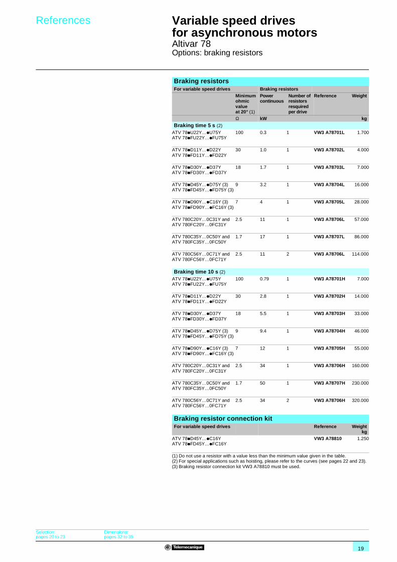
Braking resistorsFor variable speed drives Braking resistors
Minimum ohmic value at 20° (1)
Power continuous
Number of resistors resquired per drive
Reference Weight
Ω kW kg
Braking time 5 s (2)
ATV 78pU22Y…pU75YATV 78pFU22Y…pFU75Y
100 0.3 1 VW3 A78701L 1.700
ATV 78pD11Y…pD22YATV 78pFD11Y…pFD22Y
30 1.0 1 VW3 A78702L 4.000
ATV 78pD30Y…pD37YATV 78pFD30Y…pFD37Y
18 1.7 1 VW3 A78703L 7.000
ATV 78pD45Y…pD75Y (3)ATV 78pFD45Y…pFD75Y (3)
9 3.2 1 VW3 A78704L 16.000
ATV 78pD90Y…pC16Y (3)ATV 78pFD90Y…pFC16Y (3)
7 4 1 VW3 A78705L 28.000
ATV 780C20Y…0C31Y and ATV 780FC20Y…0FC31Y
2.5 11 1 VW3 A78706L 57.000
ATV 780C35Y…0C50Y and ATV 780FC35Y…0FC50Y
1.7 17 1 VW3 A78707L 86.000
ATV 780C56Y…0C71Y and ATV 780FC56Y…0FC71Y
2.5 11 2 VW3 A78706L 114.000
Braking time 10 s (2)
ATV 78pU22Y…pU75YATV 78pFU22Y…pFU75Y
100 0.79 1 VW3 A78701H 7.000
ATV 78pD11Y…pD22YATV 78pFD11Y…pFD22Y
30 2.8 1 VW3 A78702H 14.000
ATV 78pD30Y…pD37YATV 78pFD30Y…pFD37Y
18 5.5 1 VW3 A78703H 33.000
ATV 78pD45Y…pD75Y (3)ATV 78pFD45Y…pFD75Y (3)
9 9.4 1 VW3 A78704H 46.000
ATV 78pD90Y…pC16Y (3)ATV 78pFD90Y…pFC16Y (3)
7 12 1 VW3 A78705H 55.000
ATV 780C20Y…0C31Y and ATV 780FC20Y…0FC31Y
2.5 34 1 VW3 A78706H 160.000
ATV 780C35Y…0C50Y and ATV 780FC35Y…0FC50Y
1.7 50 1 VW3 A78707H 230.000
ATV 780C56Y…0C71Y and ATV 780FC56Y…0FC71Y
2.5 34 2 VW3 A78706H 320.000
Braking resistor connection kitFor variable speed drives Reference Weight
kgATV 78pD45Y…pC16YATV 78pFD45Y…pFC16Y
VW3 A78810 1.250
(1) Do not use a resistor with a value less than the minimum value given in the table.(2) For special applications such as hoisting, please refer to the curves (see pages 22 and 23).(3) Braking resistor connection kit VW3 A78810 must be used.
Selection:pages 20 to 23
Dimensions:pages 32 to 35
20
Selection 1 Variable speed drivesfor asynchronous motors 1
Altivar 78Options: braking resistors
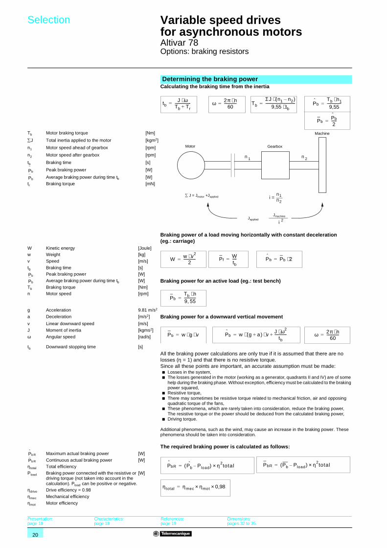
Calculating the braking time from the inertia
Determining the braking power
tbJ ω⋅
Tb Tr+------------------= ω 2π n⋅
60--------------= Tb
ΣJ n1 n2( )⋅9,55 tb⋅
----------------------------------= P
bTb n1⋅9,55----------------=
PbP
b
2------=
Tb Motor braking torque [Nm]
∑J Total inertia applied to the motor [kgm2]
n1 Motor speed ahead of gearbox [rpm]
n2 Motor speed after gearbox [rpm]
tb Braking time [s]
Peak braking power [W]
Average braking power during time tb [W]
tr Braking torque [mN]
n 2n 1
1
2i =
nn
2i
Motor Gearbox
Machine
JmachineJapplied
∑ J = Jmotor +Japplied
P
b
Pb
Braking power of a load moving horizontally with constant deceleration (eg.: carriage)
W Kinetic energy [Joule] w Weight [kg]
v Speed [m/s]
tb Braking time [s]Peak braking power [W]
Average braking power during time tb [W] Braking power for an active load (eg.: test bench) Tb Braking torque [Nm]
n Motor speed [rpm]
g Acceleration 9.81 m/s2
a Deceleration [m/s2] Braking power for a downward vertical movementv Linear downward speed [m/s] J Moment of inertia [kgms2]
ω Angular speed [rad/s]
tb Downward stopping time [s]
All the braking power calculations are only true if it is assumed that there are no losses (η = 1) and that there is no resistive torque.Since all these points are important, an accurate assumption must be made:b Losses in the system,b The losses generated in the motor (working as a generator, quadrants II and IV) are of some
help during the braking phase. Without exception, efficiency must be calculated to the braking power squared,
b Resistive torque,b There may sometimes be resistive torque related to mechanical friction, air and opposing
quadratic torque of the fans, b These phenomena, which are rarely taken into consideration, reduce the braking power,
The resistive torque or the power should be deduced from the calculated braking power, b Driving torque.
Additional phenomena, such as the wind, may cause an increase in the braking power. These phenomena should be taken into consideration.
The required braking power is calculated as follows:Maximum actual braking power [W]
Continuous actual braking power [W]
η total Total efficiency
Pload Braking power connected with the resistive or driving torque (not taken into account in the calculation). Pload can be positive or negative.
[W]
ηdrive Drive efficiency = 0.98
ηmec Mechanical efficiency
ηmot Motor efficiency
W w v2⋅2
--------------= PfWtb-----= P
b Pb 2⋅=
P
b
Pb
PbTb n⋅9 55,--------------=
Pb w g v⋅ ⋅= P
b w g a+( ) v J ω2⋅tb
--------------+⋅ ⋅= ω 2π n⋅60--------------=
P
b R
P
bR Pb Pload( ) η2×= total
η total ηmec ηmot 0,98××=
PbR Pb Pload( ) η2×= totalPb R
Presentation:page 18
Characteristics:page 18
References:page 19
Dimensions:pages 32 to 35
21
Selection (continued) 1 Variable speed drives for asynchronous motors 1
Altivar 78Options: braking resistors
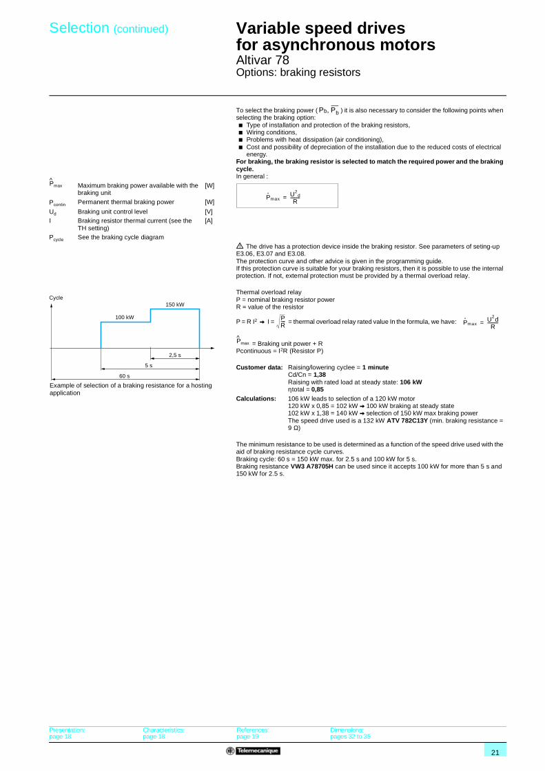
To select the braking power ( ) it is also necessary to consider the following points when selecting the braking option:b Type of installation and protection of the braking resistors,b Wiring conditions,b Problems with heat dissipation (air conditioning),b Cost and possibility of depreciation of the installation due to the reduced costs of electrical
energy.For braking, the braking resistor is selected to match the required power and the braking cycle.In general :
Maximum braking power available with the braking unit
[W]
Permanent thermal braking power [W]
Ud Braking unit control level [V]I Braking resistor thermal current (see the
TH setting)[A]
Pcycle See the braking cycle diagram
d The drive has a protection device inside the braking resistor. See parameters of seting-up E3.06, E3.07 and E3.08.The protection curve and other advice is given in the programming guide.If this protection curve is suitable for your braking resistors, then it is possible to use the internal protection. If not, external protection must be provided by a thermal overload relay.
Thermal overload relayP = nominal braking resistor powerR = value of the resistor
P = R I2 V I = = thermal overload relay rated value In the formula, we have:
= Braking unit power + RPcontinuous = I2R (Resistor P)
Customer data: Raising/lowering cyclee = 1 minuteCd/Cn = 1,38Raising with rated load at steady state: 106 kWηtotal = 0,85
Calculations: 106 kW leads to selection of a 120 kW motor120 kW x 0,85 = 102 kW V 100 kW braking at steady state102 kW x 1,38 = 140 kW V selection of 150 kW max braking powerThe speed drive used is a 132 kW ATV 782C13Y (min. braking resistance = 9 Ω)
The minimum resistance to be used is determined as a function of the speed drive used with the aid of braking resistance cycle curves.Braking cycle: 60 s = 150 kW max. for 2.5 s and 100 kW for 5 s.Braking resistance VW3 A78705H can be used since it accepts 100 kW for more than 5 s and 150 kW for 2.5 s.
Pb Pb,
Pmax
P maxU2
d
R---------=–
Pcontin
100 kW
60 s
150 kW
2,5 s
5 s
Example of selection of a braking resistance for a hosting application
Cycle
PR---- P max
U2dR
----------=
Pmax
Presentation:page 18
Characteristics:page 18
References:page 19
Dimensions:pages 32 to 35
22
Selection (continued) 1 Variable speed drives for asynchronous motors 1
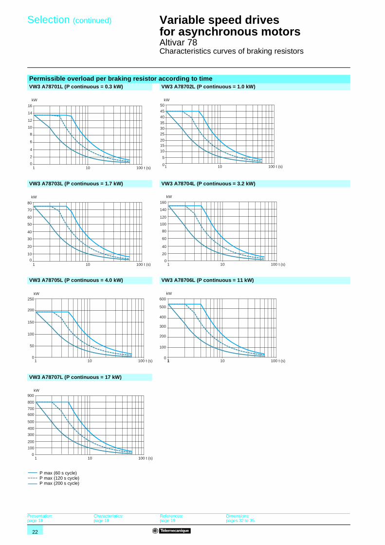
Altivar 78Characteristics curves of braking resistors
Permissible overload per braking resistor according to timeVW3 A78701L (P continuous = 0.3 kW) VW3 A78702L (P continuous = 1.0 kW)
VW3 A78703L (P continuous = 1.7 kW) VW3 A78704L (P continuous = 3.2 kW)
VW3 A78705L (P continuous = 4.0 kW) VW3 A78706L (P continuous = 11 kW)
VW3 A78707L (P continuous = 17 kW)
4
2
0
6
8
10
12
14
16
t (s)1 10
kW
100
201510
5
0
25
3035
40
45
50
t (s)1 10 100
kW
20
10
0
30
40
50
60
70
80
t (s)1 10 100
kW
40
20
0
60
80
100
120
140
160
t (s)1 10 100
kW
50
0
100
150
200
250
t (s)1 10
kW
100 1
100
0
300
200
400
500
600
t (s)1 10
kW
100
100
0
300
200
500
400
600
700
800
900
t (s)1 10
kW
100
P max (60 s cycle)P max (120 s cycle)P max (200 s cycle)
Presentation:page 18
Characteristics:page 18
References:page 19
Dimensions:pages 32 to 35
23
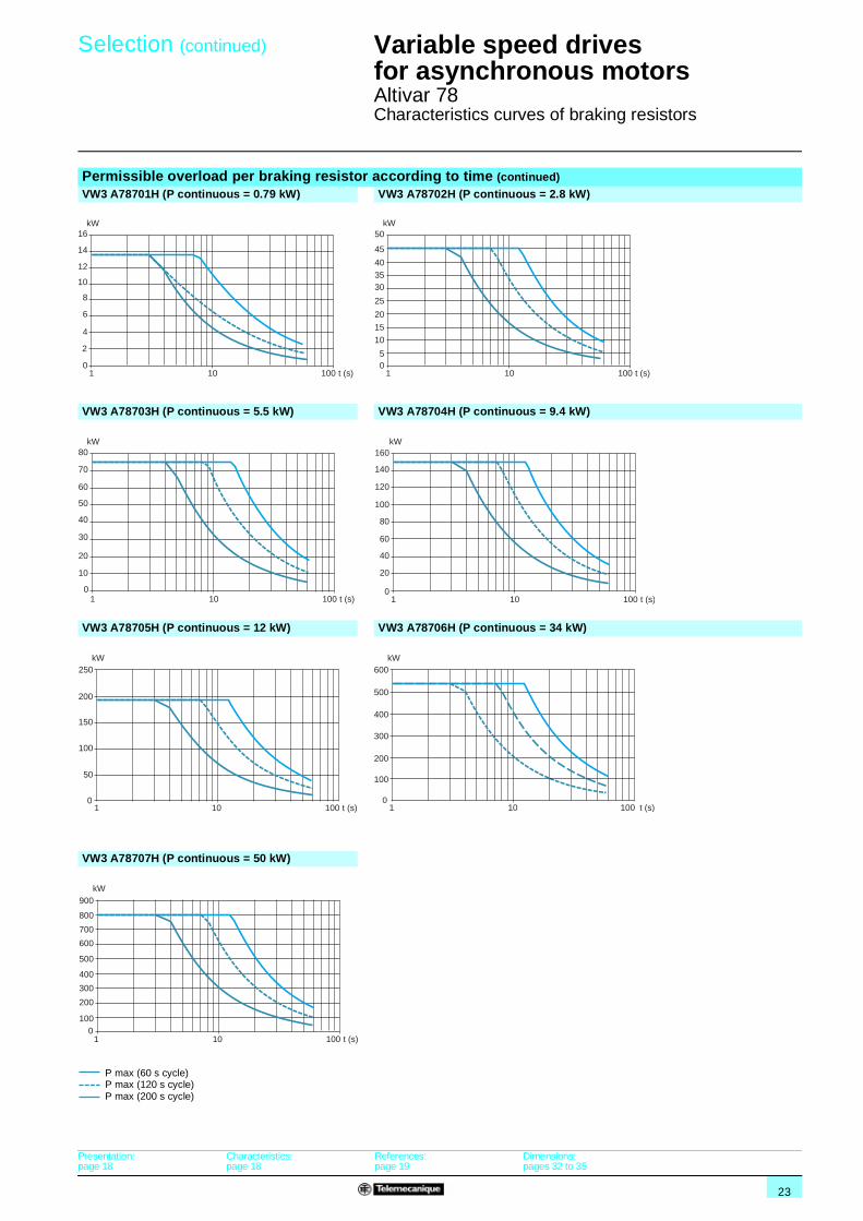
Selection (continued) 1 Variable speed drives for asynchronous motors 1
Altivar 78Characteristics curves of braking resistors
Permissible overload per braking resistor according to time (continued)VW3 A78701H (P continuous = 0.79 kW) VW3 A78702H (P continuous = 2.8 kW)
VW3 A78703H (P continuous = 5.5 kW) VW3 A78704H (P continuous = 9.4 kW)
VW3 A78705H (P continuous = 12 kW) VW3 A78706H (P continuous = 34 kW)
VW3 A78707H (P continuous = 50 kW)
4
2
0
6
8
10
12
14
16
t (s)1 10
kW
100
15
10
50
20
25
303540
45
50
t (s)1 10 100
kW
20
10
0
30
40
50
60
70
80
t (s)1 10 100
kW
40
20
0
60
80
100
120
140
160
t (s)1 10 100
kW
100
50
0
150
200
250
t (s)1 10 100
kW
t (s)1 10 100
300
200
100
0
400
500
600kW
600
1000
700
800
300
200
400
500
900
t (s)1 10 100
kW
P max (60 s cycle)P max (120 s cycle)P max (200 s cycle)
Presentation:page 18
Characteristics:page 18
References:page 19
Dimensions:pages 32 to 35
24
Presentation,characteristics,references 1
Variable speed drives for asynchronous motors 1
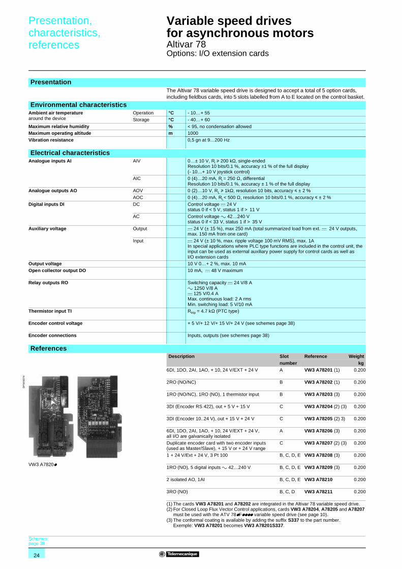
Altivar 78Options: I/O extension cards
PresentationThe Altivar 78 variable speed drive is designed to accept a total of 5 option cards, including fieldbus cards, into 5 slots labelled from A to E located on the control basket.
Environmental characteristicsAmbient air temperaturearound the device
Operation °C - 10…+ 55
Storage °C - 40…+ 60
Maximum relative humidity % < 95, no condensation allowedMaximum operating altitude m 1000
Vibration resistance 0,5 gn at 9…200 Hz
Electrical characteristicsAnalogue inputs AI AIV 0…± 10 V, Ri u 200 kΩ, single-ended
Resolution 10 bits/0.1 %, accuracy ±1 % of the full display(- 10…+ 10 V joystick control)
AIC 0 (4)…20 mA, Ri = 250 Ω, differentialResolution 10 bits/0.1 %, accuracy ± 1 % of the full display
Analogue outputs AO AOV 0 (2)…10 V, RL u 1kΩ, resolution 10 bits, accuracy y ± 2 %
AOC 0 (4)…20 mA, RL< 500 Ω, resolution 10 bits/0.1 %, accuracy y ± 2 %
Digital inputs DI DC Control voltage c 24 Vstatus 0 if < 5 V, status 1 if > 11 V
AC Control voltage a 42…240 Vstatus 0 if < 33 V, status 1 if > 35 V
Auxiliary voltage Output c 24 V (± 15 %), max 250 mA (total summarized load from ext. c 24 V outputs, max. 150 mA from one card)
Input c 24 V (± 10 %, max. ripple voltage 100 mV RMS), max. 1AIn special applications where PLC type functions are included in the control unit, the input can be used as external auxiliary power supply for control cards as well as I/O extension cards
Output voltage 10 V 0…+ 2 %, max. 10 mA
Open collector output DO 10 mA, c 48 V maximum
Relay outputs RO Switching capacity c 24 V/8 Aa 1250 V/8 Ac 125 V/0.4 AMax. continuous load: 2 A rmsMin. switching load: 5 V/10 mA
Thermistor input TI Rtrip = 4.7 kΩ (PTC type)
Encoder control voltage + 5 V/+ 12 V/+ 15 V/+ 24 V (see schemes page 38)
Encoder connections Inputs, outputs (see schemes page 38)
References Description Slot Reference Weight
number kg6DI, 1DO, 2AI, 1AO, + 10, 24 V/EXT + 24 V A VW3 A78201 (1) 0.200
2RO (NO/NC) B VW3 A78202 (1) 0.200
1RO (NO/NC), 1RO (NO), 1 thermistor input B VW3 A78203 (3) 0.200
3DI (Encoder RS 422), out + 5 V + 15 V C VW3 A78204 (2) (3) 0.200
3DI (Encoder 10..24 V), out + 15 V + 24 V C VW3 A78205 (2) 3) 0.200
6DI, 1DO, 2AI, 1AO, + 10, 24 V/EXT + 24 V, all I/O are galvanically isolated
A VW3 A78206 (3) 0.200
Duplicate encoder card with two encoder inputs (used as Master/Slave), + 15 V or + 24 V range
C VW3 A78207 (2) (3) 0.200
1 + 24 V/Ext + 24 V, 3 Pt 100 B, C, D, E VW3 A78208 (3) 0.200
1RO (NO), 5 digital inputs a 42…240 V B, C, D, E VW3 A78209 (3) 0.200
2 isolated AO, 1AI B, C, D, E VW3 A78210 0.200
3RO (NO) B, C, D VW3 A78211 0.200
(1) The cards VW3 A78201 and A78202 are integrated in the Altivar 78 variable speed drive.(2) For Closed Loop Flux Vector Control applications, cards VW3 A78204, A78205 and A78207
must be used with the ATV 78pFpppp variable speed drive (see page 10).(3) The conformal coating is available by adding the suffix S337 to the part number.
Exemple: VW3 A78201 becomes VW3 A78201S337.
VW3 A7820p
DF
5650
74
Schemes:page 38
25
Presentation,characteristics,references 1
Variable speed drives for asynchronous motors 1
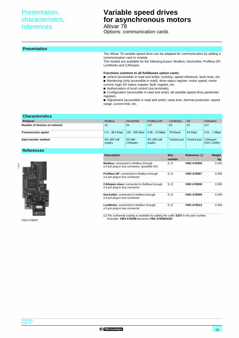
Altivar 78Options: communication cards
PresentationThe Altivar 78 variable speed drive can be adapted for communication by adding a communication card or module.The models are available for the following buses: Modbus, DeviceNet, Profibus DP, LonWorks and CANopen.
Functions common to all fieldbuses option cards:b control (accessible in read and write): run/stop, speed reference, fault reset, etc.b Monitoring (only accessible in read): drive status register, motor speed, motor current, logic I/O status register, fault, register, etc.b Authorization of local control (via terminals).b Configuration (accessible in read and write): all variable speed drive parameter registersb Adjustment (accessible in read and write): ramp time, thermal protection, speed range, current limit, etc.
CharacteristicsProtocol Modbus DeviceNet Profibus DP LonWorks N2 CANopen
Number of devices on network 31 64 127 64 32 127
Transmission speed 0.3…38.4 Kbps 125…500 Kbps 0.96…12 Mbps 78 Kbaud 9.6 Kbps 0.01…1 Mbps
Data transfer method RS 485 half duplex
RS 485 CANopen
RS 485 half duplex
Twisted pair Twisted pair CANopen (ISO 11898)
References
Description Slot Reference (1) Weightnumber kg
Modbus: connected to fieldbus through a 5-pin plug-in bus connector. (possible N2)
D, E VW3 A78306 0.300
Profibus DP: connected to fieldbus through a 5-pin plug-in bus connector
D, E VW3 A78307 0.300
CANopen slave: connected to fieldbus through a 5-pin plug-in bus connector
D, E VW3 A78308 0.300
DeviceNet: connected to fieldbus through a 5-pin plug-in bus connector
D, E VW3 A78309 0.300
LonWorks: connected to fieldbus through a 3-pin plug-in bus connector
D, E VW3 A78312 0.300
(1) The conformal coating is available by adding the suffix S337 to the part number.Exemple: VW3 A78306 becomes VW3 A78306S337VW3 A78307
533
828
Schemes:page 39

26
Combinations forcustomer assembly 1
Variable speed drives for asynchronous motors 1
Altivar 78
(1) The line chokes are supplied with the Altivar 78 variable speed drives (see pages 14 and 15).(2) For special applications such as hoisting, please refer to the curves (see pages 20 and 21).
Table showing possible combinations of Altivar 78 variable speed drive optionsMotor Altivar 78 variable speed drive
for high or standard applicationsOptions (1)
dv/dt filter Braking resistor - cycle times: 60/120/200 s (2) Braking resistor connection kitBraking time
5 sBraking time 10 s
3-phase supply voltage: 525…690 V 50/60 Hz
ATV 78pU22Y, pFU22Y VW3 A78601C VW3 A78701L VW3 A78701H –
ATV 78pU30Y, pFU30Y VW3 A78601C VW3 A78701L VW3 A78701H –ATV 78pU40Y, pFU40Y VW3 A78601C VW3 A78701L VW3 A78701H –
ATV 78pU55Y, pFU55Y VW3 A78601C VW3 A78701L VW3 A78701H –
ATV 78pU75Y, pFU75Y VW3 A78601C VW3 A78701L VW3 A78701H –ATV 78pD11Y, pFD11Y VW3 A78601C VW3 A78702L VW3 A78702H –
ATV 78pD15Y, pFD15Y VW3 A78601C VW3 A78702L VW3 A78702H –
ATV 78pD18Y, pFD18Y VW3 A78602C VW3 A78702L VW3 A78702H –ATV 78pD22Y, pFD22Y VW3 A78602C VW3 A78702L VW3 A78702H –
ATV 78pD30Y, pFD30Y VW3 A78602C VW3 A78703L VW3 A78703H –
ATV 78pD37Y, pFD37Y VW3 A78602C VW3 A78703L VW3 A78703H –ATV 78pD45Y, pFD45Y VW3 A78603C VW3 A78704L VW3 A78704H VW3 A78810
ATV 78pD55Y, pFD55Y VW3 A78603C VW3 A78704L VW3 A78704H VW3 A78810
ATV 78pD75Y, pFD75Y VW3 A78604C VW3 A78704L VW3 A78704H VW3 A78810ATV 78pD90Y, pFD90Y VW3 A78604C VW3 A78705L VW3 A78705H VW3 A78810
ATV 78pC11Y, pFC11Y VW3 A78605C VW3 A78705L VW3 A78705H VW3 A78810
ATV 78pC13Y, pFC13Y VW3 A78605C VW3 A78705L VW3 A78705H VW3 A78810ATV 78pC16Y, pFC16Y VW3 A78605C VW3 A78705L VW3 A78705H VW3 A78810
ATV 780C20Y, 0FC20Y VW3 A78606C VW3 A78706L VW3 A78706H –
ATV 780C25Y, 0FC25Y VW3 A78607C VW3 A78706L VW3 A78706H –ATV 780C31Y, 0FC31Y VW3 A78608C VW3 A78706L VW3 A78706H –
ATV 780C35Y, 0FC35Y VW3 A78609C VW3 A78707L VW3 A78707H –
ATV 780C45Y, 0FC45Y VW3 A78609C VW3 A78707L VW3 A78707H –ATV 780C50Y, 0FC50Y VW3 A78609C VW3 A78707L VW3 A78707H –
ATV 780C56Y, 0FC56Y VW3 A78610C 2 x VW3 A78706L 2 x VW3 A78706H –
ATV 780C63Y, 0FC63Y VW3 A78610C 2 x VW3 A78706L 2 x VW3 A78706H –ATV 780C71Y, 0FC71Y VW3 A78610C 2 x VW3 A78706L 2 x VW3 A78706H –
Pages 10 and 25 16 19 19
27
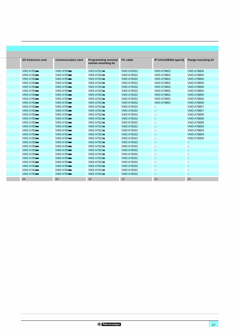
11
I/O Extension card Communication card Programming terminal remote mounting kit
PC cable IP 54 kit (NEMA type12) Flange mounting kit
VW3 A782pp VW3 A783pp VW3 A7810p VW3 A78332 VW3 A78801 VW3 A78806
VW3 A782pp VW3 A783pp VW3 A7810p VW3 A78332 VW3 A78801 VW3 A78806VW3 A782pp VW3 A783pp VW3 A7810p VW3 A78332 VW3 A78801 VW3 A78806
VW3 A782pp VW3 A783pp VW3 A7810p VW3 A78332 VW3 A78801 VW3 A78806
VW3 A782pp VW3 A783pp VW3 A7810p VW3 A78332 VW3 A78801 VW3 A78806VW3 A782pp VW3 A783pp VW3 A7810p VW3 A78332 VW3 A78801 VW3 A78806
VW3 A782pp VW3 A783pp VW3 A7810p VW3 A78332 VW3 A78801 VW3 A78806
VW3 A782pp VW3 A783pp VW3 A7810p VW3 A78332 VW3 A78801 VW3 A78806VW3 A782pp VW3 A783pp VW3 A7810p VW3 A78332 VW3 A78801 VW3 A78806
VW3 A782pp VW3 A783pp VW3 A7810p VW3 A78332 – VW3 A78807
VW3 A782pp VW3 A783pp VW3 A7810p VW3 A78332 – VW3 A78807VW3 A782pp VW3 A783pp VW3 A7810p VW3 A78332 – VW3 A78808
VW3 A782pp VW3 A783pp VW3 A7810p VW3 A78332 – VW3 A78808
VW3 A782pp VW3 A783pp VW3 A7810p VW3 A78332 – VW3 A78808VW3 A782pp VW3 A783pp VW3 A7810p VW3 A78332 – VW3 A78809
VW3 A782pp VW3 A783pp VW3 A7810p VW3 A78332 – VW3 A78809
VW3 A782pp VW3 A783pp VW3 A7810p VW3 A78332 – VW3 A78809VW3 A782pp VW3 A783pp VW3 A7810p VW3 A78332 – VW3 A78809
VW3 A782pp VW3 A783pp VW3 A7810p VW3 A78332 – –
VW3 A782pp VW3 A783pp VW3 A7810p VW3 A78332 – –VW3 A782pp VW3 A783pp VW3 A7810p VW3 A78332 – –
VW3 A782pp VW3 A783pp VW3 A7810p VW3 A78332 – –
VW3 A782pp VW3 A783pp VW3 A7810p VW3 A78332 – –VW3 A782pp VW3 A783pp VW3 A7810p VW3 A78332 – –
VW3 A782pp VW3 A783pp VW3 A7810p VW3 A78332 – –
VW3 A782pp VW3 A783pp VW3 A7810p VW3 A78332 – –VW3 A782pp VW3 A783pp VW3 A7810p VW3 A78332 – –
24 25 12 12 12 13
28
Dimensions 1 Variable speed drives for asynchronous motors 1
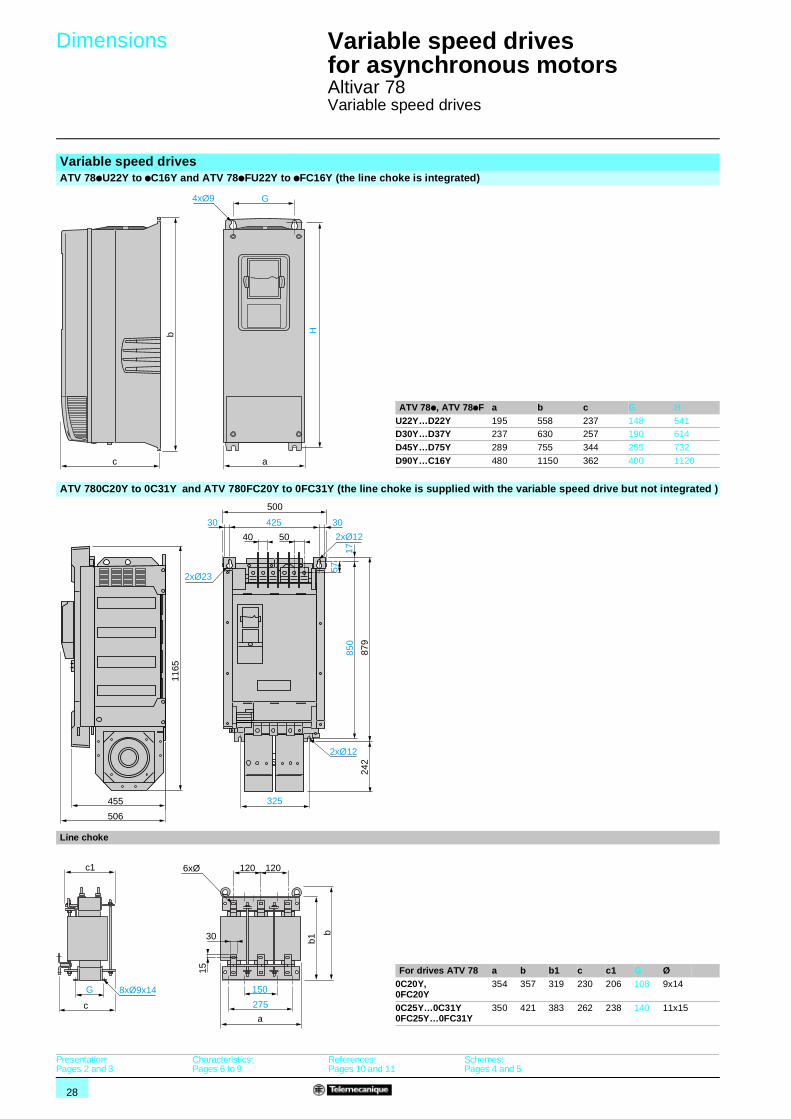
Altivar 78Variable speed drives
Variable speed drivesATV 78pU22Y to pC16Y and ATV 78pFU22Y to pFC16Y (the line choke is integrated)
ATV 78p, ATV 78pF a b c G HU22Y…D22Y 195 558 237 148 541D30Y…D37Y 237 630 257 190 614
D45Y…D75Y 289 755 344 255 732
D90Y…C16Y 480 1150 362 400 1120
ATV 780C20Y to 0C31Y and ATV 780FC20Y to 0FC31Y (the line choke is supplied with the variable speed drive but not integrated )
Line choke
For drives ATV 78 a b b1 c c1 G Ø0C20Y, 0FC20Y
354 357 319 230 206 108 9x14
0C25Y…0C31Y 0FC25Y…0FC31Y
350 421 383 262 238 140 11x15
H
c a
4xØ9 G
b
2xØ12
325
500
5040
850
57
879
242
17
3030 425
2xØ23
2xØ12
455
1165
506
15
150
275
30
a
120 120
b1
b
G
c
c1 6xØ
8xØ9x14
Presentation:Pages 2 and 3
Characteristics:Pages 6 to 9
References:Pages 10 and 11
Schemes:Pages 4 and 5
29
Dimensions (continued) 1 Variable speed drives for asynchronous motors 1
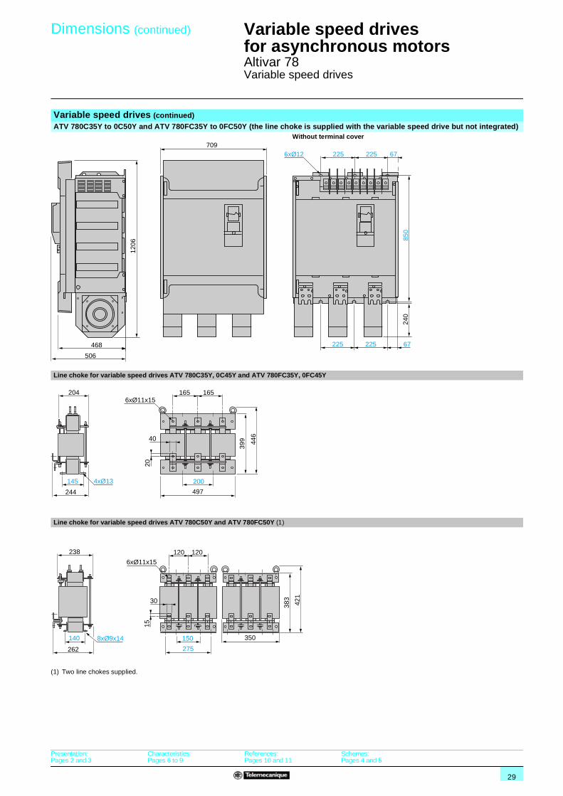
Altivar 78Variable speed drives
Variable speed drives (continued)ATV 780C35Y to 0C50Y and ATV 780FC35Y to 0FC50Y (the line choke is supplied with the variable speed drive but not integrated)
Without terminal cover
Line choke for variable speed drives ATV 780C35Y, 0C45Y and ATV 780FC35Y, 0FC45Y
Line choke for variable speed drives ATV 780C50Y and ATV 780FC50Y (1)
(1) Two line chokes supplied.
468
709
1206
240
506
850
225 225 67
225 225 67
6xØ12
2 2 2
200145
244
204
40
20
399 44
6
497
165 1656xØ11x15
4xØ13
6xØ11x15
30
15
150
275
350
120 120
140
262
421
383
238
8xØ9x14
Presentation:Pages 2 and 3
Characteristics:Pages 6 to 9
References:Pages 10 and 11
Schemes:Pages 4 and 5
30
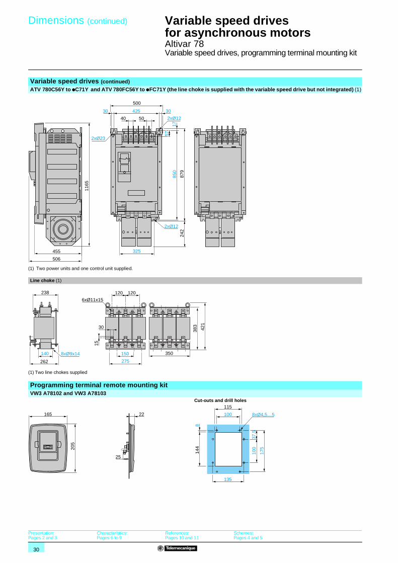
Dimensions (continued) 1 Variable speed drives for asynchronous motors 1
Altivar 78Variable speed drives, programming terminal mounting kit
Variable speed drives (continued)ATV 780C56Y to pC71Y and ATV 780FC56Y to pFC71Y (the line choke is supplied with the variable speed drive but not integrated) (1)
(1) Two power units and one control unit supplied.
Line choke (1)
(1) Two line chokes supplied
Programming terminal remote mounting kitVW3 A78102 and VW3 A78103
Cut-outs and drill holes
455
1165
506
2xØ12
325
500
5040
850
57
879
242
17
3030 425
2xØ23
2xØ12
6xØ11x15
30
15
150
275
350
120 120
140
262
421
383
238
8xØ9x14
25
22165
205
115
100 8xØ4,5…5
814
4
37,5
100
175
135
Presentation:Pages 2 and 3
Characteristics:Pages 6 to 9
References:Pages 10 and 11
Schemes:Pages 4 and 5
31
Dimensions 1 Variable speed drives for asynchronous motors 1
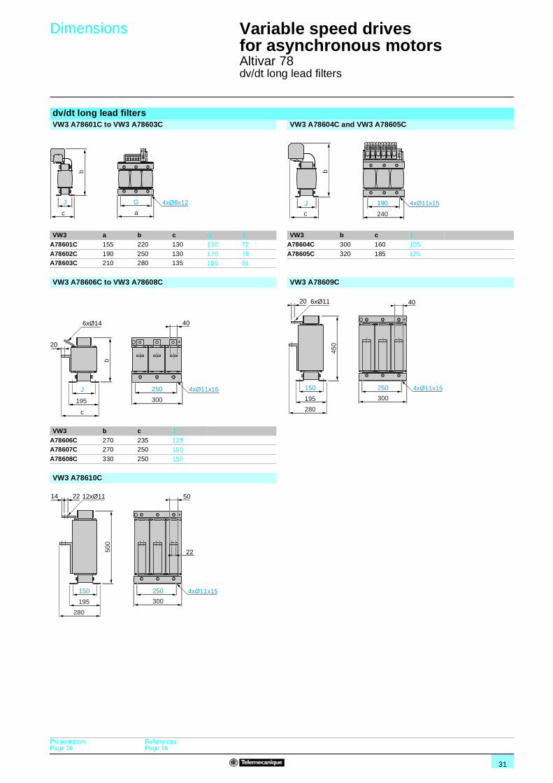
Altivar 78dv/dt long lead filters
dv/dt long lead filtersVW3 A78601C to VW3 A78603C VW3 A78604C and VW3 A78605C
VW3 a b c G J VW3 b c JA78601C 155 220 130 130 72 A78604C 300 160 105
A78602C 190 250 130 170 78 A78605C 320 185 125A78603C 210 280 135 180 81
VW3 A78606C to VW3 A78608C VW3 A78609C
VW3 b c JA78606C 270 235 125A78607C 270 250 150
A78608C 330 250 150
VW3 A78610C
J G
ac
4xØ8x12
b
190
240
4xØ11x15J
c
b
20
250
300
4xØ11x15
6xØ14
b
J
195
c
40
250
300
4xØ11x15
20 406xØ11
450
150
195
280
12xØ11
22
250
500
300
150
195
280
4xØ11x15
2214 50
Presentation:Page 16
References:Page 16

32
Dimensions 1 Variable speed drives for asynchronous motors 1
Altivar 78Braking resistors
Braking resistors: braking time 5 sVW3 A78701L
Mounting recommendations (1)
(1) When vertical mounted, the cables must be located at the bottom.
VW3 A78702L and VW3 A78703LMounting recommendations (1)
VW3 a G (1) When vertical mounted, the cables must be located at the bottom.A78702L 426 326
A78703L 725 626
VW3 A78704LMounting recommendations (1)
(1) When vertical mounted, the cables must be located at the bottom.
405
405
60
386
2xØ5,3
8
31
73˚
244xØ6,2x5,8
102
60 1000 a
G= =
2020
90
124
117
=
2020260
24
238
660 =
760
960
4xØ6,2x5,8
101
96
Presentation:Page 18
Characteristics:Page 18
References:Page 19
Selection:Pages 20 to 23
33
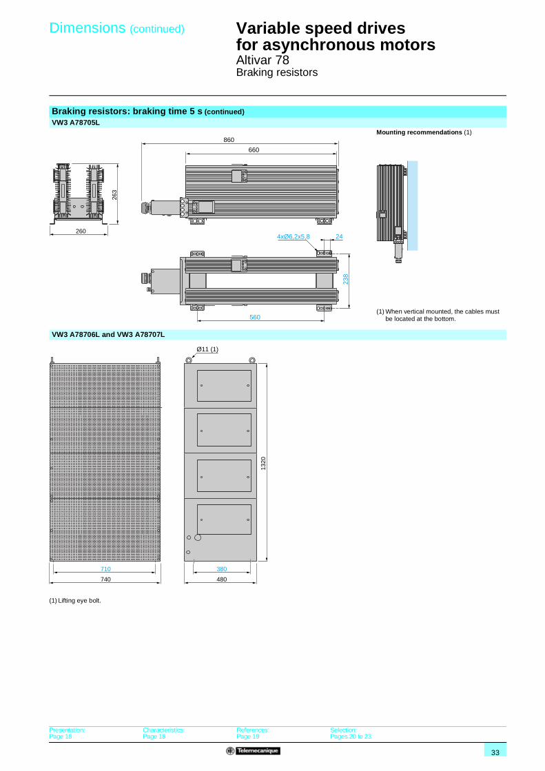
Dimensions (continued) 1 Variable speed drives for asynchronous motors 1
Altivar 78Braking resistors
Braking resistors: braking time 5 s (continued)VW3 A78705L
Mounting recommendations (1)
(1) When vertical mounted, the cables must be located at the bottom.
VW3 A78706L and VW3 A78707L
(1) Lifting eye bolt.
238
560
260
263
660
860
244xØ6,2x5,8
380
480
1320
710
740
Ø11 (1)
Presentation:Page 18
Characteristics:Page 18
References:Page 19
Selection:Pages 20 to 23
34
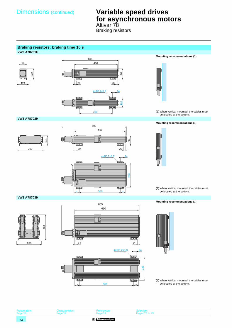
Dimensions (continued) 1 Variable speed drives for asynchronous motors 1
Altivar 78Braking resistors
Braking resistors: braking time 10 sVW3 A78701H
Mounting recommendations (1)
(1) When vertical mounted, the cables must be located at the bottom.
VW3 A78702HMounting recommendations (1)
(1) When vertical mounted, the cables must be located at the bottom.
VW3 A78703HMounting recommendations (1)
(1) When vertical mounted, the cables must be located at the bottom.
20 20124
60
102
360
244xØ6,2x5,8
122
120
460
605
=
2020260
24
238
560 =
660
800
4xØ6,2x5,8
101
96
238
560
260
263
660
805
244xØ6,2x5,8
==
14 14
Presentation:Page 18
Characteristics:Page 18
References:Page 19
Selection:Pages 20 to 23
35
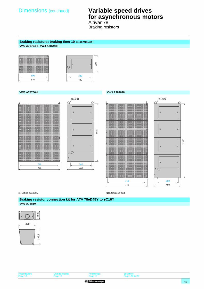
Dimensions (continued) 1 Variable speed drives for asynchronous motors 1
Altivar 78Braking resistors
Braking resistors: braking time 10 s (continued)VW3 A78704H, VW3 A78705H
VW3 A78706H VW3 A78707H
(1) Lifting eye bolt. (1) Lifting eye bolt.
Braking resistor connection kit for ATV 78pD45Y to pC16YVW3 A78810
380
480
300
500
530
380
480
1020
710
740
Ø11(1)
380
48013
20710
740
Ø11(1)
103,
8
258
238,
2
Presentation:Page 18
Characteristics:Page 18
References:Page 19
Selection:Pages 20 to 23
36
Mounting recommendations 1
Variable speed drives for asynchronous motors 1
Altivar 78
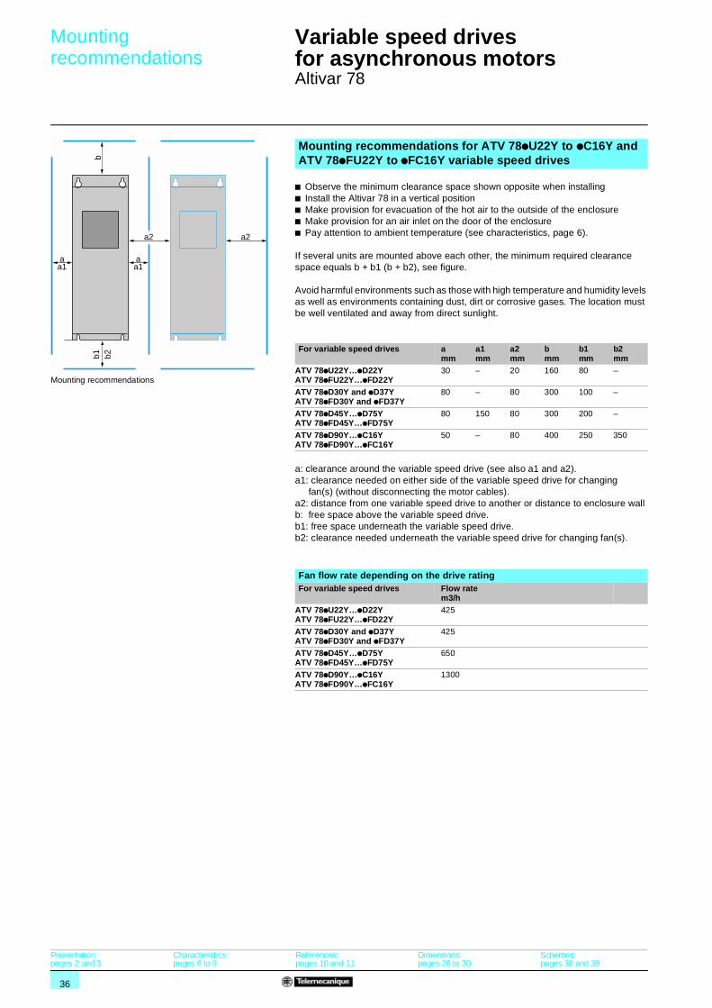
Mounting recommendations for ATV 78pU22Y to pC16Y and ATV 78pFU22Y to pFC16Y variable speed drives
b Observe the minimum clearance space shown opposite when installingb Install the Altivar 78 in a vertical positionb Make provision for evacuation of the hot air to the outside of the enclosureb Make provision for an air inlet on the door of the enclosureb Pay attention to ambient temperature (see characteristics, page 6).
If several units are mounted above each other, the minimum required clearance space equals b + b1 (b + b2), see figure.
Avoid harmful environments such as those with high temperature and humidity levels as well as environments containing dust, dirt or corrosive gases. The location must be well ventilated and away from direct sunlight.
For variable speed drives amm
a1mm
a2mm
bmm
b1mm
b2mm
ATV 78pU22Y…pD22YATV 78pFU22Y…pFD22Y
30 – 20 160 80 –
ATV 78pD30Y and pD37YATV 78pFD30Y and pFD37Y
80 – 80 300 100 –
ATV 78pD45Y…pD75YATV 78pFD45Y…pFD75Y
80 150 80 300 200 –
ATV 78pD90Y…pC16YATV 78pFD90Y…pFC16Y
50 – 80 400 250 350
a: clearance around the variable speed drive (see also a1 and a2).a1: clearance needed on either side of the variable speed drive for changing
fan(s) (without disconnecting the motor cables).a2: distance from one variable speed drive to another or distance to enclosure wallb: free space above the variable speed drive.b1: free space underneath the variable speed drive.b2: clearance needed underneath the variable speed drive for changing fan(s).
Fan flow rate depending on the drive ratingFor variable speed drives Flow rate
m3/hATV 78pU22Y…pD22YATV 78pFU22Y…pFD22Y
425
ATV 78pD30Y and pD37YATV 78pFD30Y and pFD37Y
425
ATV 78pD45Y…pD75YATV 78pFD45Y…pFD75Y
650
ATV 78pD90Y…pC16YATV 78pFD90Y…pFC16Y
1300
aa1
bb1 b2
a2
aa1
a2
Mounting recommendations
Presentation:pages 2 and 3
Characteristics:pages 6 to 9
References:pages 10 and 11
Dimensions:pages 28 to 30
Schemes:pages 38 and 39
37
Mounting recommendations (continued) 1
Variable speed drives for asynchronous motors 1
Altivar 78
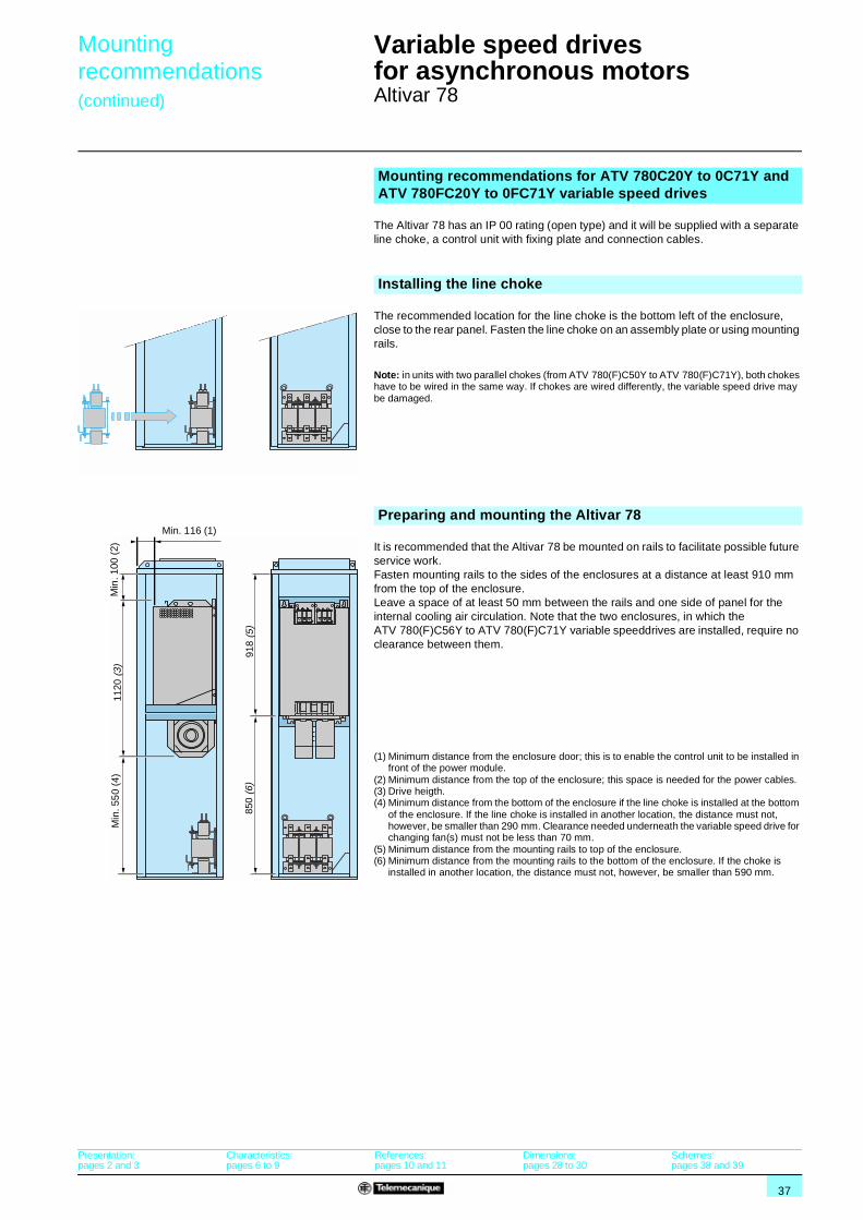
Mounting recommendations for ATV 780C20Y to 0C71Y and ATV 780FC20Y to 0FC71Y variable speed drives
The Altivar 78 has an IP 00 rating (open type) and it will be supplied with a separate line choke, a control unit with fixing plate and connection cables.
Installing the line choke
The recommended location for the line choke is the bottom left of the enclosure, close to the rear panel. Fasten the line choke on an assembly plate or using mounting rails.
Note: in units with two parallel chokes (from ATV 780(F)C50Y to ATV 780(F)C71Y), both chokes have to be wired in the same way. If chokes are wired differently, the variable speed drive may be damaged.
Preparing and mounting the Altivar 78
It is recommended that the Altivar 78 be mounted on rails to facilitate possible future service work. Fasten mounting rails to the sides of the enclosures at a distance at least 910 mm from the top of the enclosure. Leave a space of at least 50 mm between the rails and one side of panel for the internal cooling air circulation. Note that the two enclosures, in which the ATV 780(F)C56Y to ATV 780(F)C71Y variable speeddrives are installed, require no clearance between them.
(1) Minimum distance from the enclosure door; this is to enable the control unit to be installed in front of the power module.
(2) Minimum distance from the top of the enclosure; this space is needed for the power cables.(3) Drive heigth.(4) Minimum distance from the bottom of the enclosure if the line choke is installed at the bottom
of the enclosure. If the line choke is installed in another location, the distance must not, however, be smaller than 290 mm. Clearance needed underneath the variable speed drive for changing fan(s) must not be less than 70 mm.
(5) Minimum distance from the mounting rails to top of the enclosure.(6) Minimum distance from the mounting rails to the bottom of the enclosure. If the choke is
installed in another location, the distance must not, however, be smaller than 590 mm.
918
(5)
1120
(3)
850
(6)
Min. 116 (1)
Min
. 100
(2)
Min
. 55
0 (4
)
Presentation:pages 2 and 3
Characteristics:pages 6 to 9
References:pages 10 and 11
Dimensions:pages 28 to 30
Schemes:pages 38 and 39
38
Schemes 1 Variable speed drives for asynchronous motors 1
Altivar 78
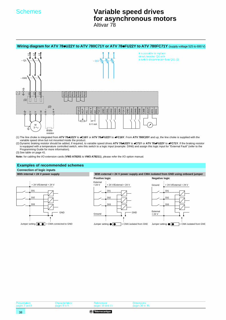
Wiring diagram for ATV 78pU22Y to ATV 780C71Y or ATV 78pFU22Y to ATV 780FC71Y (supply voltage 525 to 690 V)
(1) The line choke is integrated from ATV 78pU22Y to pC16Y or ATV 78pFU22Y to pFC16Y. From ATV 780C20Y and up, the line choke is supplied with the variable speed drive but not mounted inside the product.
(2) Dynamic braking resistor should be added, if required, to variable speed drives ATV 78pU22Y to pC71Y or ATV 78pFU22Y to pFC71Y. If the braking resistor is equipped with a temperature controlled switch, wire this switch to a logic input (example: DIN6) and assign this logic input for “External Fault” (refer to the Programming Guide for more information).
(3) See table on page 41.
Note: for cabling the I/O extension cards (VW3 A78201 to VW3 A78211), please refer the I/O option manual.
Examples of recommended schemesConnection of logic inputsWith internal + 24 V power supply With external + 24 V power supply and CMA isolated from GND using onboard jumper
Positive logic Negative logic
W R +
R –
U V AI1
–
DIN
1
DIN
2
DIN
3
DIN
4
DIN
5
DIN
6
CM
B
GN
D
CM
A
+10
V
+24
V
GN
D
+24
V
AI1
+
AI2
–
AI2
+
AO
1+A
O1
–
DO
1
L1 L2 L3
M 3
(2)
– Q1
– KM1
L1 L2 L3
A1
(1)
RO
1
RO
1
RO
1
RO
2
RO
2
RO
2
X-Y mA
– Q11
Brake resistor
It is possible to replace circuit-breaker Q1 with a switch-disconnector-fuse Q11 (3)
DI1
GND
DI2
DI3
Jumper setting: = CMA connected to GND
+ 24 V/External + 24 V
DI1
GND
DI2
DI3
Jumper setting: = CMA isolated from GND
External + 24 V + 24 V/External + 24 V
Ground
DI1
DI2
DI3
Jumper setting: = CMA isolated from GND
External + 24 V
+ 24 V/External + 24 VGround
Presentation:pages 2 and 3
Characteristics:pages 6 to 9
References:pages 10 and 11
Dimensions:pages 28 to 35
39
Schemes (continued) 1 Variable speed drives for asynchronous motors 1
Altivar 78
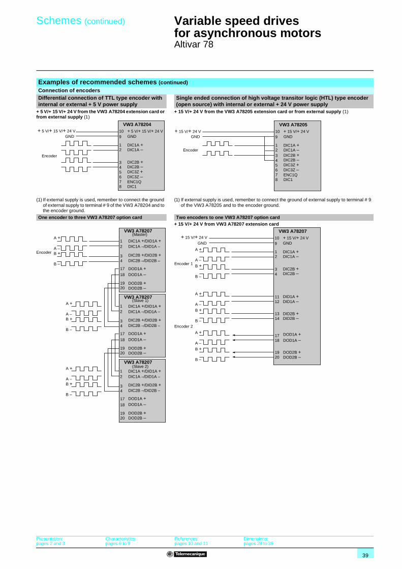
Examples of recommended schemes (continued)Connection of encodersDifferential connection of TTL type encoder with internal or external + 5 V power supply
Single ended connection of high voltage transitor logic (HTL) type encoder (open source) with internal or external + 24 V power supply
+ 5 V/+ 15 V/+ 24 V from the VW3 A78204 extension card or from external supply (1)
(1) If external supply is used, remenber to connect the ground of external supply to terminal # 9 of the VW3 A78204 and to the encoder ground.
+ 15 V/+ 24 V from the VW3 A78205 extension card or from external supply (1)
(1) If external supply is used, remenber to connect the ground of external supply to terminal # 9 of the VW3 A78205 and to the encoder ground.
One encoder to three VW3 A78207 option card Two encoders to one VW3 A78207 option card+ 15 V/+ 24 V from VW3 A78207 extension card
+ 5 V/+ 15 V/+ 24 VGND
10 + 5 V/+ 15 V/+ 24 V
DIC1A +DIC1A –
DIC2B +DIC2B –DIC3Z +DIC3Z –ENC1QDIC1
GND
12
345678
9
VW3 A78204
Encoder
GND10 + 15 V/+ 24 V
DIC1A +DIC1A –DIC2B +DIC2B –DIC3Z +DIC3Z –ENC1QDIC1
GND
12345678
9
VW3 A78205+ 15 V/+ 24 V
Encoder
1 DIC1A +/DID1A +DIC1A –/DID1A –
DIC2B +/DID2B +DIC2B –/DID2B –
DOD1A +DOD1A –
DOD2B +DOD2B –
34
17
18
1920
2
VW3 A78207
1
A +
A –B +
B –
A +
A –B +
B –
A +
A –B +
B –
34
17
18
1920
2
VW3 A78207
1
34
17
18
1920
2
VW3 A78207
DIC1A +/DID1A +DIC1A –/DID1A –
DIC2B +/DID2B +DIC2B –/DID2B –
DOD1A +DOD1A –
DOD2B +DOD2B –
DIC1A +/DID1A +DIC1A –/DID1A –
DIC2B +/DID2B +DIC2B –/DID2B –
DOD1A +DOD1A –
DOD2B +DOD2B –
Encoder
(Master)
(Slave 1)
(Slave 2)
A +
A –
B +
B –
A +
A –
B +
B –
A +
A –
B +
B –
GND10 + 15 V/+ 24 V
DIC1A +DIC1A –
DIC2B +DIC2B –
DID1A +DID1A –
DID2B +DID2B –
GND
12
34
1112
1314
1718
1920
9
VW3 A78207
DOD1A +DOD1A –
DOD2B +DOD2B –
+ 15 V/+ 24 V
Encoder 1
Encoder 2
Presentation:pages 2 and 3
Characteristics:pages 6 to 9
References:pages 10 and 11
Dimensions:pages 28 to 35
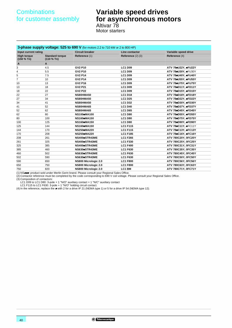
40
Combinations for customer assembly 1
Variable speed drives for asynchronous motors 1
Altivar 78Motor starters
3-phase supply voltage: 525 to 690 V (for motors 2.2 to 710 kW or 2 to 800 HP) Input current rating Circuit breaker Line contactor Variable speed drive High torque (150 % Tn)
Standard torque (110 % Tn)
Reference (1) Reference (2) (3) Reference (4)
A A3 4.5 GV2 P10 LC1 D09 ATV 78pU22Y, pFU22Y4 5.5 GV2 P10 LC1 D09 ATV 78pU30Y, pFU30Y5 7.5 GV2 P14 LC1 D09 ATV 78pU40Y, pFU40Y7 10 GV2 P14 LC1 D09 ATV 78pU55Y, pFU55Y10 13 GV2 P16 LC1 D09 ATV 78pU75Y, pFU75Y13 18 GV2 P21 LC1 D09 ATV 78pD11Y, pFD11Y18 22 GV2 P22 LC1 D09 ATV 78pD15Y, pFD15Y22 27 NS80HMA50 LC1 D18 ATV 78pD18Y, pFD18Y27 34 NS80HMA50 LC1 D25 ATV 78pD22Y, pFD22Y34 41 NS80HMA50 LC1 D32 ATV 78pD30Y, pFD30Y41 52 NS80HMA65 LC1 D40 ATV 78pD37Y, pFD37Y52 62 NS80HMA65 LC1 D65 ATV 78pD45Y, pFD45Y62 80 NS100pMA100 LC1 D80 ATV 78pD55Y, pFD55Y80 100 NS160pMA150 LC1 D80 ATV 78pD75Y, pFD75Y100 125 NS160pMA150 LC1 D80 ATV 78pD90Y, pFD90Y125 144 NS160pMA150 LC1 F115 ATV 78pC11Y, pFC11Y
144 170 NS250pMA220 LC1 F115 ATV 78pC13Y, pFC13Y170 208 NS250pMA220 LC1 F185 ATV 78pC16Y, pFC16Y208 261 NS400pSTR43ME LC1 F265 ATV 780C20Y, 0FC20Y261 325 NS400pSTR43ME LC1 F330 ATV 780C25Y, 0FC25Y325 385 NS400pSTR43ME LC1 F400 ATV 780C31Y, 0FC31Y385 460 NS630pSTR43ME LC1 F630 ATV 780C35Y, 0FC35Y460 502 NS630pSTR43ME LC1 F630 ATV 780C45Y, 0FC45Y502 590 NS630pSTR43ME LC1 F630 ATV 780C50Y, 0FC50Y590 650 NS800 Micrologic 2.0 LC1 F800 ATV 780C56Y, 0FC56Y650 750 NS800 Micrologic 2.0 LC1 F800 ATV 780C63Y, 0FC63Y750 820 NS800 Micrologic 2.0 LC1 BM ATV 780C71Y, 0FC71Y(1) NSppp: product sold under Merlin Gerin brand. Please consult your Regional Sales Office.(2) Contactor reference must be completed by the code corresponding to 690 V coil voltage. Please consult your Regional Sales Office.(3) Composition of contactors:
LC1 D09 to LC1 D80: 3-pole + 1 "N/O" auxiliary contact + 1 "N/C" auxiliary contactLC1 F115 to LC1 F630: 3-pole + 1 "N/O" holding circuit contact.
(4) In the reference, replace the p with 2 for a drive IP 21 (NEMA type 1) or 5 for a drive IP 54 (NEMA type 12).
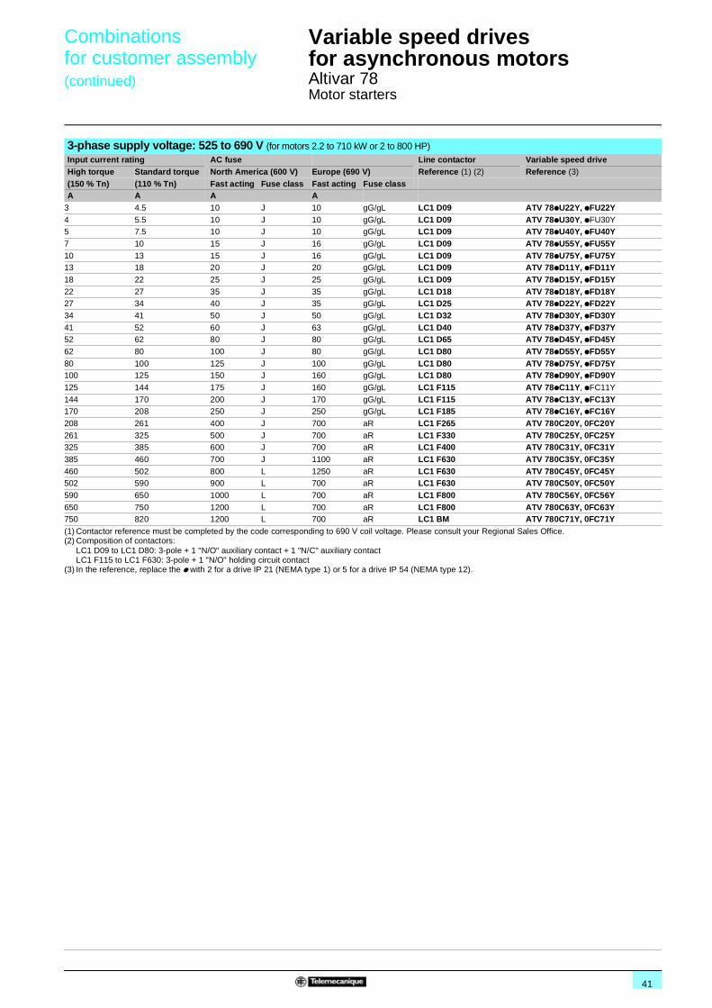
41
Combinations for customer assembly(continued) 1
Variable speed drives for asynchronous motors 1
Altivar 78Motor starters
3-phase supply voltage: 525 to 690 V (for motors 2.2 to 710 kW or 2 to 800 HP) Input current rating AC fuse Line contactor Variable speed drive High torque Standard torque North America (600 V) Europe (690 V) Reference (1) (2) Reference (3)
(150 % Tn) (110 % Tn) Fast acting Fuse class Fast acting Fuse classA A A A
3 4.5 10 J 10 gG/gL LC1 D09 ATV 78pU22Y, pFU22Y4 5.5 10 J 10 gG/gL LC1 D09 ATV 78pU30Y, pFU30Y5 7.5 10 J 10 gG/gL LC1 D09 ATV 78pU40Y, pFU40Y7 10 15 J 16 gG/gL LC1 D09 ATV 78pU55Y, pFU55Y10 13 15 J 16 gG/gL LC1 D09 ATV 78pU75Y, pFU75Y13 18 20 J 20 gG/gL LC1 D09 ATV 78pD11Y, pFD11Y18 22 25 J 25 gG/gL LC1 D09 ATV 78pD15Y, pFD15Y22 27 35 J 35 gG/gL LC1 D18 ATV 78pD18Y, pFD18Y27 34 40 J 35 gG/gL LC1 D25 ATV 78pD22Y, pFD22Y34 41 50 J 50 gG/gL LC1 D32 ATV 78pD30Y, pFD30Y41 52 60 J 63 gG/gL LC1 D40 ATV 78pD37Y, pFD37Y52 62 80 J 80 gG/gL LC1 D65 ATV 78pD45Y, pFD45Y62 80 100 J 80 gG/gL LC1 D80 ATV 78pD55Y, pFD55Y80 100 125 J 100 gG/gL LC1 D80 ATV 78pD75Y, pFD75Y100 125 150 J 160 gG/gL LC1 D80 ATV 78pD90Y, pFD90Y125 144 175 J 160 gG/gL LC1 F115 ATV 78pC11Y, pFC11Y
144 170 200 J 170 gG/gL LC1 F115 ATV 78pC13Y, pFC13Y170 208 250 J 250 gG/gL LC1 F185 ATV 78pC16Y, pFC16Y208 261 400 J 700 aR LC1 F265 ATV 780C20Y, 0FC20Y261 325 500 J 700 aR LC1 F330 ATV 780C25Y, 0FC25Y325 385 600 J 700 aR LC1 F400 ATV 780C31Y, 0FC31Y385 460 700 J 1100 aR LC1 F630 ATV 780C35Y, 0FC35Y460 502 800 L 1250 aR LC1 F630 ATV 780C45Y, 0FC45Y502 590 900 L 700 aR LC1 F630 ATV 780C50Y, 0FC50Y590 650 1000 L 700 aR LC1 F800 ATV 780C56Y, 0FC56Y650 750 1200 L 700 aR LC1 F800 ATV 780C63Y, 0FC63Y750 820 1200 L 700 aR LC1 BM ATV 780C71Y, 0FC71Y(1) Contactor reference must be completed by the code corresponding to 690 V coil voltage. Please consult your Regional Sales Office.(2) Composition of contactors:
LC1 D09 to LC1 D80: 3-pole + 1 "N/O" auxiliary contact + 1 "N/C" auxiliary contactLC1 F115 to LC1 F630: 3-pole + 1 "N/O" holding circuit contact
(3) In the reference, replace the p with 2 for a drive IP 21 (NEMA type 1) or 5 for a drive IP 54 (NEMA type 12).

42
0
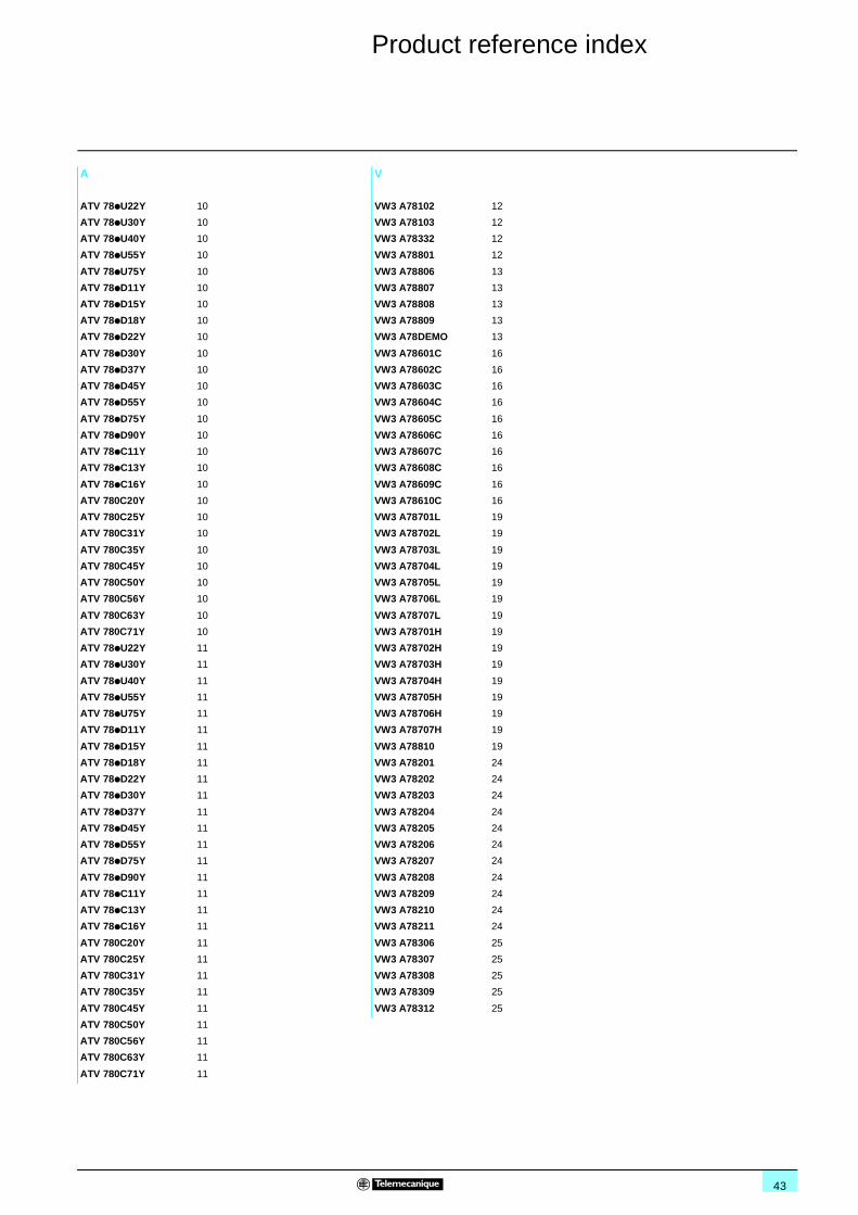
43
Product reference index 6
A
ATV 78pU22Y 10
ATV 78pU30Y 10
ATV 78pU40Y 10
ATV 78pU55Y 10
ATV 78pU75Y 10
ATV 78pD11Y 10
ATV 78pD15Y 10
ATV 78pD18Y 10
ATV 78pD22Y 10
ATV 78pD30Y 10
ATV 78pD37Y 10
ATV 78pD45Y 10
ATV 78pD55Y 10
ATV 78pD75Y 10
ATV 78pD90Y 10
ATV 78pC11Y 10
ATV 78pC13Y 10
ATV 78pC16Y 10
ATV 780C20Y 10
ATV 780C25Y 10
ATV 780C31Y 10
ATV 780C35Y 10
ATV 780C45Y 10
ATV 780C50Y 10
ATV 780C56Y 10
ATV 780C63Y 10
ATV 780C71Y 10
ATV 78pU22Y 11
ATV 78pU30Y 11
ATV 78pU40Y 11
ATV 78pU55Y 11
ATV 78pU75Y 11
ATV 78pD11Y 11
ATV 78pD15Y 11
ATV 78pD18Y 11
ATV 78pD22Y 11
ATV 78pD30Y 11
ATV 78pD37Y 11
ATV 78pD45Y 11
ATV 78pD55Y 11
ATV 78pD75Y 11
ATV 78pD90Y 11
ATV 78pC11Y 11
ATV 78pC13Y 11
ATV 78pC16Y 11
ATV 780C20Y 11
ATV 780C25Y 11
ATV 780C31Y 11
ATV 780C35Y 11
ATV 780C45Y 11
ATV 780C50Y 11
ATV 780C56Y 11
ATV 780C63Y 11
ATV 780C71Y 11
V
VW3 A78102 12
VW3 A78103 12
VW3 A78332 12
VW3 A78801 12
VW3 A78806 13
VW3 A78807 13
VW3 A78808 13
VW3 A78809 13
VW3 A78DEMO 13
VW3 A78601C 16
VW3 A78602C 16
VW3 A78603C 16
VW3 A78604C 16
VW3 A78605C 16
VW3 A78606C 16
VW3 A78607C 16
VW3 A78608C 16
VW3 A78609C 16
VW3 A78610C 16
VW3 A78701L 19
VW3 A78702L 19
VW3 A78703L 19
VW3 A78704L 19
VW3 A78705L 19
VW3 A78706L 19
VW3 A78707L 19
VW3 A78701H 19
VW3 A78702H 19
VW3 A78703H 19
VW3 A78704H 19
VW3 A78705H 19
VW3 A78706H 19
VW3 A78707H 19
VW3 A78810 19
VW3 A78201 24
VW3 A78202 24
VW3 A78203 24
VW3 A78204 24
VW3 A78205 24
VW3 A78206 24
VW3 A78207 24
VW3 A78208 24
VW3 A78209 24
VW3 A78210 24
VW3 A78211 24
VW3 A78306 25
VW3 A78307 25
VW3 A78308 25
VW3 A78309 25
VW3 A78312 25


ART. 807180 05 / 2005
DIA
2ED
2050
501E
N
Schneider Electric Industries SAS
Head Office89, bd Franklin Roosevelt92506 Rueil-Malmaison CedexFrance
www.schneider-electric.comwww.telemecanique.com
Due to evolution of standards and equipment, the characteristics indicated in texts and images of thisdocument do not constitute a commitment on our part without confirmation.Design: Schneider ElectricPhotos: Schneider ElectricPrinted by: