common air conditioning electro- mechanical … air conditioning electro-mechanical failures and the...
TRANSCRIPT

Common Air Conditioning Electro-Mechanical failures and the tools
used to diagnose them
R. MavridesJanuary 2017
Page 2Testo USA, Presentation Title (version), Author, Date, Confidentiality
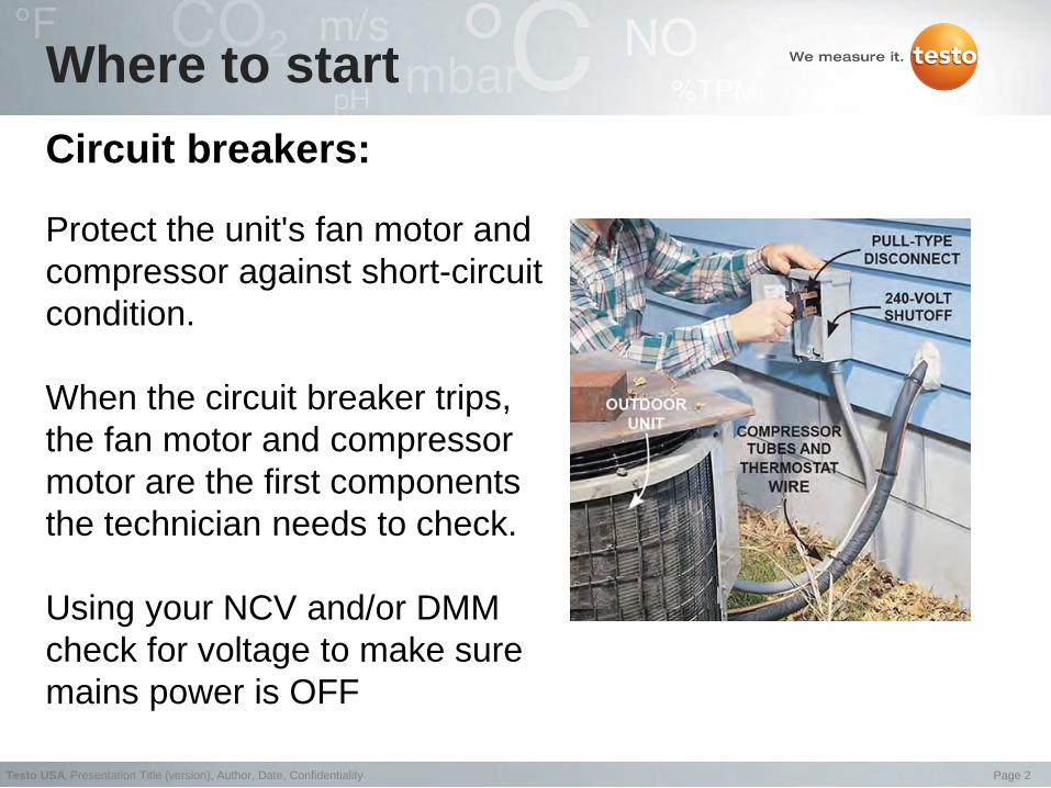
Circuit breakers:
Protect the unit's fan motor and compressor against short-circuit condition.
When the circuit breaker trips, the fan motor and compressor motor are the first components the technician needs to check.
Using your NCV and/or DMM check for voltage to make sure mains power is OFF
Where to start

Page 3Testo USA, Presentation Title (version), Author, Date, Confidentiality
Compressor and fan controls:Can wear out, especially when the A/C system short cycles, as is common when a system is oversized.
Corrosion of wire and terminals is also a problem in many systems, electrical connections and contacts should be checked during a professional service call.
Compressor and fan controls failures:

Page 4Testo USA, Presentation Title (version), Author, Date, Confidentiality
Compressor bearing failure or lockup may be caused by poor piping practices, which lead to oil clogging the system and result in insufficient oil return to the compressor and locking up the bearings.
If the bearings don't lock up and continue to wear during these conditions, the rotor will lower into the stator housing, shorting out the windings and trip the breaker.
Compressors and Fan motor failures
Page 5Testo USA, Presentation Title (version), Author, Date, Confidentiality
Compressors and Fan motor failures
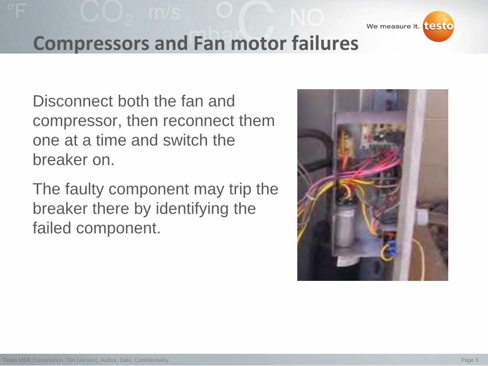
Disconnect both the fan and compressor, then reconnect them one at a time and switch the breaker on.
The faulty component may trip the breaker there by identifying the failed component.

Page 6Testo USA, Presentation Title (version), Author, Date, Confidentiality
• A more challenging condition which is difficult to diagnose is when the compressor motor is overheating, over time, and ultimately trips the circuit breaker
• Clamp meters designed to accurately measure both AC voltage and AC current are especially useful. They let you measure current without breaking the electrical circuit.
• Using your clamp meter check the voltage and current draw of the compressor, if it exceeds the manufacturer’s normal operating specification you need to consider whether mechanical conditions may have resulted in this type of failure
Compressors and Fan motor and failures

Page 7Testo USA, Presentation Title (version), Author, Date, Confidentiality
System failure is often blamed on a defective compressor, but this failure may be attributable to mechanical system failure cause by poor installation or service attributable to:
• Oversized system resulting in short cycle operation
• Under sized system resulting extended run time
• Poor piping practices resulting in oil not adequately returning to the compressor during the run cycle.
• High discharge temperatures creating acids in the oil.
• Insufficient airflow across the evaporator and condenser coils.
• Extremely low suction pressures.
• Liquid refrigerant flooding back into the compressor.
Compressors failure cause by improper installation or service

Page 8Testo USA, Presentation Title (version), Author, Date, Confidentiality
Troubleshooting check list (mechanical)Using the manufacturer’s mechanical specs:
• Inspect the oil level in the compressor
• Check for incorrect piping installation resulting in oil not adequately returning to the compressor during the run cycle
• Check for proper airflow across the evaporator and condenser coils.
• Check superheat and sub cooling
• Make sure refrigerant is not flooding back into the compressor
• Check for correct amount of refrigerant
• Test for refrigerant leaks using a leak detector

Page 9Testo USA, Presentation Title (version), Author, Date, Confidentiality
• Measure airflow through the evaporator coil
• Verify the correct electric control sequence and make sure that the heating system and cooling system cannot operate simultaneously
• Inspect electric terminals, clean and tighten connections, and apply a non-conductive coating if necessary
• Oil motors and check belts for tightness and wear
• Check the accuracy of the thermostat
Assuming that all the above are ok and your superheat and subcooling are within the manufacture’s specs, excessive current may be due to shorted or grounded windings, bearing fatigue, a bad capacitor, or a faulty start relay.
Troubleshooting check list (mechanical)
Page 10Testo USA, Presentation Title (version), Author, Date, Confidentiality
Compressor: To check the compressor for electrical problems, remove the electrical terminal cover and check the following external connections.
1. Check line voltage at the junction box with the compressor off. Low line voltage causes the motor to draw more current than normal and may result in overheating and premature failure. Line voltage that is too high will cause excessive inrush current at motor start, again leading to premature failure.
2. Check line voltage at the motor terminals with the compressor running. The voltage should be within 10 percent of the motor rating.
Troubleshooting check list (electrical)
Page 11Testo USA, Presentation Title (version), Author, Date, Confidentiality
Troubleshooting check list (electrical)1. Check running current. The readings should not exceed the
manufacturers' full-load rated amps during heavy load periods. Low amps are normal during light-load conditions. Excessive high current may be due to shorted or grounded windings, a bad capacitor, a faulty start relay, or an indication of excessive bearing fatigue
2. Disconnect the compressor, using your clamp meter’s resistance input, measure and verify the compressor’s motor winding resistance, if the reading are not within the manufacturer specs, the compressor needs to be replaced
3. Check the capacitance of the starter capacitor, the coil resistance and contacts of the start relay. Based on these measurements a determination can be made as to which of these components has failed.
Page 12Testo USA, Presentation Title (version), Author, Date, Confidentiality
Worn Contactor:• There are three contactors in a unit: one for the compressor, which is
noted above, one for the condenser fan motor, and one for the blower motor. The contactors engage when there is a need for cooling or heating, making an electrical connection. This starts the compressor and motors. Arcing and pitting can form on the contactor making it hard for the electrical current to pass and start the particular motor
Thermostat:• This device that tells the system when to start cooling and when to
stop. Before calling an HVAC service company, make sure the thermostat is on. Many times, the thermostat is accidentally turned off or set to heat mode.
Troubleshooting check list (electrical)

Page 13Testo USA, Presentation Title (version), Author, Date, Confidentiality
AC/R COMPONENTS

Page 14Testo USA, Presentation Title (version), Author, Date, Confidentiality
AC/R COMPONENTS

Page 15Testo USA, Presentation Title (version), Author, Date, Confidentiality
TYPICAL RESIDENTIAL AIR CONDITIONING SYSTEM DIAGRAM
Page 16Testo USA, Presentation Title (version), Author, Date, Confidentiality
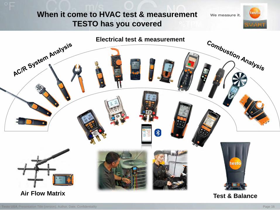
When it come to HVAC test & measurement TESTO has you covered
Electrical test & measurement
Test & BalanceAir Flow Matrix

Page 17Testo USA, Presentation Title (version), Author, Date, Confidentiality
THANK YOU