community air monitoring branch standard … · this standard operating procedure (sop) describes...
TRANSCRIPT

California Environmental Protection Agency
COMMUNITY AIR MONITORING BRANCH
STANDARD OPERATING PROCEDURE
FOR PICARRO G2401 ANALYZER FOR CO2/CO/CH4
CAMB SOP 261
First Edition
Monitoring and Laboratory Division November 2018
DISCLAIMER: Mention of any trade name or commercial product in this Standard Operating Procedure does not constitute endorsement or recommendation of this product by the Air Resources Board. Specific brand names and instrument descriptions listed in the Standard Operating Procedure are for equipment used by the Air Resources Board laboratory.

i
Table of Contents 1. GENERAL INFORMATION ................................................................................................. 1 2. INSTALLATION PROCEDURE ........................................................................................... 3 3. SOFTWARE MENUS .......................................................................................................... 9 4. CALIBRATION PROCEDURE ...........................................................................................10 5. ROUTINE SERVICE CHECKS ..........................................................................................11 6. TROUBLESHOOTING .......................................................................................................13 APPENDIX A. PICARRO G-2401 MONTHLY MAINTENANCE CHECK SHEET. .....................14 APPENDIX B. Example Picarro Calibration Report ..................................................................15 APPENDIX C. Example External Valve Sequencer Configuration ............................................17
ii
Acronyms AC Alternating Current AWG American Wire Gauge CAMB Community Air Monitoring Branch CARB California Air Resources Board CRDS Cavity Ring-Down Spectroscopy NOAA National Oceanographic and Atmospheric Administration OD Outside Diameter RH Relative Humidity

CAMB SOP 261 Picarro G2401 Analyzer
First Edition, November 2018 Page 1 of 17
1
1. GENERAL INFORMATION
1.1 Introduction This Standard Operating Procedure (SOP) describes procedures used by the California Air Resources Board (CARB) Community Air Monitoring Branch (CAMB) to operate the Picarro G-2401 analyzer for measurements of methane/carbon monoxide/carbon dioxide/water vapor in ambient air. This procedure supplements the G-2401 instrument manual by describing any modifications in operating procedures implemented by the CAMB and is not intended to be a replacement for the instrument manual. NOTE: Operators must read the G-2401 instrument manual prior to startup to familiarize themselves with the operation of the instrument
1.2 Principle of Operation:
• This analyzer uses the Cavity Ring-Down Spectroscopy (CRDS) to measure gases of interest. CRDS is a form of laser absorption spectroscopy where a laser pulse is trapped in a highly reflective cavity.
• The Picarro G-2401 CRDS uses laser diodes and a cavity with three highly reflective mirrors which support a continuous traveling light wave.
• After the laser turns on, the cavity rapidly fills with the laser’s light. The laser turns off when light intensity in the cavity reaches a threshold. The light bounces between mirrors and a small amount of light is lost with each bounce. Therefore, the intensity of light reaching the detector decreases until it reaches zero. The time it takes for the laser light to decay to zero is related to the concentration of gases in the cavity.
• The CRDS dramatically increases the effective pathlength that the laser’s light travels. For a Picarro cavity of only 25 cm in length, the effective pathlength within the cavity can be over 20 kilometers.
• The system specifications are provided in Table 1.

CAMB SOP 261 Picarro G2401 Analyzer
First Edition, November 2018 Page 2 of 17
2
Table 1. System specifications System Specifications
Measurement Technique Cavity Ring-Down Spectroscopy (CRDS)
Measurement Cell Temperature Control +/- 0.005 °C
Measurement Cell Pressure Control +/- 0.0002 atm
Sample Temperature -10 to 45 °C
Sample Pressure 300 to 1000 Torr (40 to 133 kPa)
Sample Flow Rate < 0.4 slm at 760 Torr, no filtration required
Sample Humidity < 99 % R.H. non-condensing @ 40 °C, no drying required
Ambient Temperature Range 10 to 35 °C (operating) -10 to 50 °C (storage)
Ambient Humidity < 99 % R.H. non-condensing
Accessories (Included) Pump (external), keyboard, mouse, LCD monitor (optional)
Outputs RS-232, Ethernet, USB, analog (optional) 0 – 10 V
Fittings ¼” Swagelok ®
Dimensions Analyzer: 17” w x 7” h x 17.55” d (43.18 x 17.78 x 44.57 cm) not incl. 0.5” feet External Pump: 7.5” w x 4” h x 11” d (19 x 10.2 x 28 cm)
Installation Benchtop (standard) or 19” rack mount chassis (optional)
Weight 59.3 lbs (26.9 kg), includes external pump
Power Requirements 100 - 240 VAC, 47 - 63 Hz (auto-sensing), < 260 W start-up (total); ~ 110 W (analyzer) + 80 W (pump) at steady state
1.3 Safety Precautions
• DO NOT operate in an explosive atmosphere.
• DO NOT operate in the presence of flammable gases or vapors.
• DO NOT operate in a wet environment.
• The G-2401 analyzer contains no user serviceable components other than the vacuum pump. Do not attempt repairs other than the replacement of the vacuum pump.
• The G-2401 analyzer is classified as a Class 1 Embedded Laser Product.
• CAUTION: Class 3B invisible laser radiation when open. Avoid exposure to the beam.
• Do not open any enclosures within the instrument. Failure to do so could result in exposure to Class 3B laser radiation, which can permanently damage eyes and skin.

CAMB SOP 261 Picarro G2401 Analyzer
First Edition, November 2018 Page 3 of 17
3
• The inlet bulkhead connector can be hot when the instrument is operating, or after it has been shut down. Take care when connecting gas lines or working at the rear of the instrument to wear protective gloves or avoid contact with these surfaces.
• Although the analyzer components can be optionally configured for rack mounting, they require supports in the rack, such as a shelf or side L-bracket.
• Some of the analyzer components are heavy. To avoid injury, please proper lifting procedure when moving or installing the analyzer.
1.4 Limitations/Interferences:
• The G-2401 analyzer should be operated within an ambient temperature range of 10 to 35 °C.
• Under normal operating conditions, the precision check gas cylinder should be set to NO MORE THAN five (5) psi output pressure. Failure to do so may cause irreparable damage to the instrument.
• The laser is tuned to different wavelengths that correspond to the unique spectral absorption lines of the target analytes. Therefore, there are no interferences under ambient air condition.
2. INSTALLATION PROCEDURE
2.1 List of Tools/Supplies
• Tools that include open end wrenches, screwdriver set, and wire cutters/strippers.
• Three-conductor cable (min. AWG 20 gauge)
• Rack mountable shelf to hold instrument (19” wide by 23” deep).
• ¼ in OD Teflon or equivalent tubing made of inert materials.
• Small bypass pump (optional).
2.2 Physical Inspection
• The G-2401 analyzer is shipped with the following standard equipment:
• One Analyzer Module - includes all of the data acquisition, control, and communications hardware and firmware to perform all gas handling, spectral collection and analysis.
• One Pump Module – provides vacuum required for sample gas sequencing into and out of the Analyzer.

CAMB SOP 261 Picarro G2401 Analyzer
First Edition, November 2018 Page 4 of 17
4
• One Flexible tubing – with 3/8” Swagelok fitting on each end to connect the vacuum pump to the Analyzer Module.
• One USB flash drive – pre-loaded with back-up software
• One A/C power cables (North America only)
• One Certificate of compliance
• One User Manual If any of these items are missing contact Picarro for a replacement. Check items carefully and report any damage to AQSB management and Picarro.
2.3 Basic Analyzer Setup
• Place the Analyzer on a bench top or flat surface or mount the instrument on a rack.
• Place the External Vacuum Pump nearby or on the floor.
• Attach the gas line between the Analyzer vacuum port and the External Vacuum Pump. See Figure 1. Hand tighten the nut, then make an additional 1/4th turn with an 11/16” wrench.
• Connect the AC power cable to the External Vacuum Pump but do not plug it in.
• Connect the computer monitor, keyboard, and mouse as shown in Figure 1.
• The sampling tubing material can be polytetrafluoroethylene (PTFE), Bev-A-Line, Synflex or metal.
Figure 1. Back of Analyzer.
CAMB SOP 261 Picarro G2401 Analyzer
First Edition, November 2018 Page 5 of 17
5
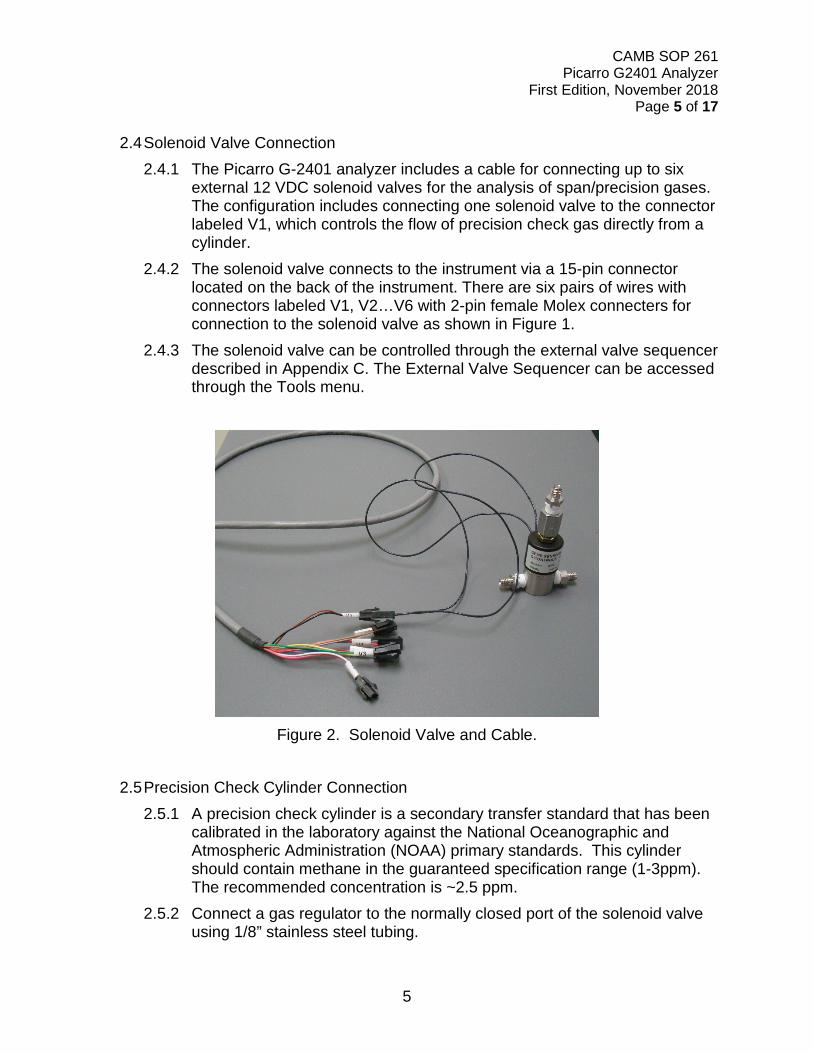
2.4 Solenoid Valve Connection 2.4.1 The Picarro G-2401 analyzer includes a cable for connecting up to six
external 12 VDC solenoid valves for the analysis of span/precision gases. The configuration includes connecting one solenoid valve to the connector labeled V1, which controls the flow of precision check gas directly from a cylinder.
2.4.2 The solenoid valve connects to the instrument via a 15-pin connector located on the back of the instrument. There are six pairs of wires with connectors labeled V1, V2…V6 with 2-pin female Molex connecters for connection to the solenoid valve as shown in Figure 1.
2.4.3 The solenoid valve can be controlled through the external valve sequencer described in Appendix C. The External Valve Sequencer can be accessed through the Tools menu.
Figure 2. Solenoid Valve and Cable.
2.5 Precision Check Cylinder Connection
2.5.1 A precision check cylinder is a secondary transfer standard that has been calibrated in the laboratory against the National Oceanographic and Atmospheric Administration (NOAA) primary standards. This cylinder should contain methane in the guaranteed specification range (1-3ppm). The recommended concentration is ~2.5 ppm.
2.5.2 Connect a gas regulator to the normally closed port of the solenoid valve using 1/8” stainless steel tubing.

CAMB SOP 261 Picarro G2401 Analyzer
First Edition, November 2018 Page 6 of 17
6
2.5.3 Connect the normally open port on the solenoid valve to the sample inlet on the left rear of the Picarro analyzer. Connect the remaining (middle) port on the solenoid valve to the sample manifold as shown in Figures 3 and 4.
NOTE: If the G-2401 analyzer is being operated in conjunction with other ambient gas analyzers that are calibrated daily then a separate inlet/manifold should be used.
Figure 3. Solenoid Valve Connections.
Figure 4. Solenoid Valve Connected to Cylinder.

CAMB SOP 261 Picarro G2401 Analyzer
First Edition, November 2018 Page 7 of 17
7
2.6 Start Up and Shut Down Procedures:
2.6.1 Start-Up 2.6.1.1 Turn on External Vacuum Pump, the Analyzer, and computer
monitor. The software controlling the instrument will start automatically. Do not start the analyzer until after attaching and turning on the External Vacuum Pump. Do not disconnect the vacuum line while the analyzer is running.
2.6.1.2 If the analyzer is plugged in and the power is off then it can be started by pressing the round power switch located on the lower front panel of the instrument shown in Figure 5.
2.6.1.3 The instrument won’t report data until all of its operating conditions are reached. This typically takes less than 30 minutes, but depending on ambient temperature, the analyzer can take up to 1 hour to stabilize.
Figure 5. Location of Power Switch.
2.6.2 Normal Start Up Messages
2.6.2.1 Temperature Locked: The system waits for the warm box (“WB”-the temperature-controlled electronics and wavelength monitor chamber) to reach operating temperature. Similarly, the temperature of the hot box (“HB”-the temperature-controlled chamber containing the analyzer’s optical cavity and gas
Power Switch
CAMB SOP 261 Picarro G2401 Analyzer
First Edition, November 2018 Page 8 of 17
8
handling system) is stabilized. The duration of this step can range from 5 to 60 minutes depending on the ambient temperature and how much time has elapsed since the last startup.
2.6.2.2 Entering Measurement: Spectral scanning has started. Concentration measurements will be available in approximately 30 seconds.
2.6.2.3 Pressure stabilizing/locked: The valve control system begins to allow flow through the analyzer and stabilize the pressure inside the cavity.
2.6.2.4 Measuring: This is the normal mode of operation after startup has completed.
2.6.3 Shut-Down
2.6.3.1 Method A (recommended): Place the computer mouse onto the bar labeled “Shutdown” on the G-2401 trace gas analyzer window and left click the mouse (Figure 6).
2.6.3.2 Method B: If the instrument fails to shut down properly using Method A then press the power switch on the front of the instrument and hold for five seconds. The instrument should proceed with automatic shutdown.
2.6.3.3 Method C: This method should only be used in the case where the G-2401 is completely unresponsive and the mouse no longer functions. Unplug the power cord from the receptacle. Wait for approximately two minutes. Replace the power cord in the receptacle and the instrument should restart automatically.

CAMB SOP 261 Picarro G2401 Analyzer
First Edition, November 2018 Page 9 of 17
9
Figure 6. Shutdown Procedure.
3. SOFTWARE MENUS
3.1 Settings Menu Left clicking on the Settings menu pulls down a menu that has one entry “Change GUI Mode from Standard to Service”. This is the access point to a password protected service mode where additional operational and measurement parameters are displayed. Selecting and clicking on this entry opens the CRDS controller. This is reserved for Picarro service operators only.
3.2 View Menu
This menu has three entries 3.2.1 Lock/unlock time axis when zoomed: when locked, forces the graphs to
display the same time scale during zoom.
Left click mouse here to shut down

CAMB SOP 261 Picarro G2401 Analyzer
First Edition, November 2018 Page 10 of 17
10
3.2.2 Show/Hide statistics: toggles the measurement statistics display. 3.2.3 Show/Hide instrument status: toggles the instruments status display.
3.3 Tools Menu
This menu has three entries: 3.3.1 User Calibration: opens the user calibration window (default password is
“Picarro”). The password can be reset in the QuickGui.ini in the directory: “C:\Picarro\G2000\AppConfig\Config\QuickGUI\”
3.3.2 UserCalPassword=Picarro Show/Hide Valve. 3.3.3 Sequencer GUI: toggles the display of the External valve sequencer
window.
3.4 Help Menu “About” displays the version number of the instrument.
4. CALIBRATION PROCEDURE
4.1 Calibration Transfer Standards and Equipment:
• Two NOAA certified gas standards.
• High purity gas regulator.
• 1/8” tubing for connection to analyzer inlet.
4.2 Calibration Procedures 4.2.1 Detailed instructions on calibrating the G-2401 are shown in Appendix E,
Picarro Application Note AN015 “Calibrating the Picarro Analyzer”. 4.2.2 In summary, two NOAA certified standards that bracket the ambient range
of concentration for methane, nominally 1.800 and 2.500 ppm, are analyzed for ten minutes each. The instrument is allowed to stabilize for five minutes and the results from the following five minutes are averaged for each of the standards. These results are then plotted with the true concentration on the vertical axis and the instrument response on the horizontal axis.
4.2.3 A linear best-fit equation is then calculated from the results and this slope and offset is entered into the User Calibration as “Slope” and “Offset” (Figure 7).The User Calibration window can be accessed through the Tools menu.

CAMB SOP 261 Picarro G2401 Analyzer
First Edition, November 2018 Page 11 of 17
11
4.2.4 A verification of the calibration should be conducted periodically (nominally once per year) and compared to the previous laboratory comparison and factory calibration. The results of this verification should be collected and submitted to CAMB management for review. Under normal operating conditions, the calibration factors on the instrument should not be changed by field personnel.
Figure 7. User Calibration Slope and Offset Input Screen
5. ROUTINE SERVICE CHECKS
5.1 General Information: The following routine service checks should be performed in accordance with the maintenance schedule (Table 2). Perform the routine service checks at the prescribed intervals at a minimum. The CAMB Monthly Quality Control Check Sheet (Appendix A) should be completed and submitted monthly to the station operator’s supervisor. The station operator should keep a copy of the Quality Control Check Sheet in the air monitoring station.

CAMB SOP 261 Picarro G2401 Analyzer
First Edition, November 2018 Page 12 of 17
12
Table 2. Maintenance Schedule.
5.2 Daily Check
Review hourly average data on data logger and check instrument status through emails sent by CARBLogger for any error messages. Review hourly average results.
5.3 Weekly Check Visually check the instrument display for proper operation. Check the instrument time and adjust if not within +/- 2 minutes. Change external filters.
5.4 Monthly Check Complete and submit monthly maintenance check sheet to supervisor.
5.5 Annual Check Perform a verification of the instrument calibration with certified standards.
5.6 As Needed Check Replace pump or pump diaphragms about every 10,000 hours.
Task Per formed
Daily Weekly Monthly Annually As Needed
Review Hourly Average Data X Review Daily Precision Data X Check Instrument Display for Errors X Check Instrument Time X Change External Filter X Complete and Submit Monthly Maintenance Check sheet X
Perform Calibration Verification with Certified Standards X
Replace Pump or Diaphragms X

CAMB SOP 261 Picarro G2401 Analyzer
First Edition, November 2018 Page 13 of 17
13
6. TROUBLESHOOTING
In the case of a power failure, the Picarro G-2401 analyzer is designed to re-start when power is restored. Occasionally this causes the instrument computer to lock up when re-booting. Should this condition occur, the G-2401 should be unplugged briefly and then re-started as normally. If any conditions occur with the G-2401 such as erratic sample concentrations or unusual error messages (i.e. scan timeout error) etc. Picarro technical support should be consulted.

CAMB SOP 261 Picarro G2401 Analyzer
First Edition, November 2018 Page 14 of 17
14
APPENDIX A. PICARRO G-2401 MONTHLY MAINTENANCE CHECK SHEET. MONTHLY QUALITY MAINTENANCE CHECK SHEET
Location: Month/Year: Station Number: Technician: Property Number: S/N: Agency: OPERATOR INSTRUCTIONS: 1. Daily Checks: Check instrument status display. Record any errors in
comments section. 2. Weekly Checks: Check computer time and adjust if necessary. Visual check of instrument readings: results should fall within
the following ranges: CO2 - >375 ppm and <600 ppm CH4 - >1.7 ppm and <3.0 ppm
Date:
Precision Cylinder Pressure Change inlet particulate filter (5 micron). Date: / / / 3. Monthly Checks: Complete and submit Monthly Maintenance Check sheet. 4. Annually: Perform calibration check with certified standards. Date of last calibration check:
Date: Comments or Maintenance Performed:
Reviewed by: Date:

CAMB SOP 261 Picarro G2401 Analyzer
First Edition, November 2018 Page 15 of 17
15
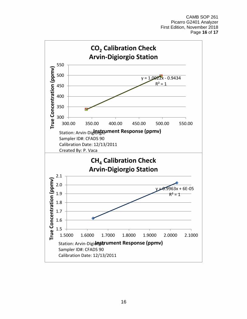
APPENDIX B. Example Picarro Calibration Report
Methane, Carbon Dioxide, Carbon Monoxide Analyzer
ID Information: Cylinder Information:
Station Name: Arvin-Digiorgio Serial # CC309300 CC309765 Site #: 15-249 CO2 Conc. (ppm): 497.13 337.7
AIRS #: 60295002 CH4 Conc. (ppb): 2023.1 1621.7
Serial #: CFADS90 Cylinder Press.
(psi): 1890 1860 Station
Address: 19405 Buena Vista
Ave. Outlet Press. (psi): <5 <5 Agency: CARB Certification Date: 11/1/2010 10/1/2010
Calibration Date: 12/13/2011 Expiration Date: 11/1/2012 10/1/2012
Report Date: 12/27/2011 Note: Each cylinder analyzed for 10 minutes, average of last 5 minutes used for calibration. Calibration Results:
Concentration (ppm) TRUE CFADS90 % Difference
CO2_01 497.13 496.98 0.030 CO2_02 337.7 337.90 -0.059 CH4_01 2.0231 2.0306 -0.371 CH4_02 1.6217 1.6277 -0.370
Regression Analysis: CO2 Slope 1.0022 CO2 Intercept 0.9434 CH4 Slope 0.9963 CH4 Intercept 6.00E-05 Comments: Cylinders analyzed by direct injection into sample inlet Calibrated by:
Checked by:
CAMB SOP 261 Picarro G2401 Analyzer
First Edition, November 2018 Page 16 of 17
16
y = 1.0022x - 0.9434R² = 1
300
350
400
450
500
550
300.00 350.00 400.00 450.00 500.00 550.00
True
Con
cent
ratio
n (p
pmv)
Instrument Response (ppmv)
CO2 Calibration CheckArvin-Digiorgio Station
Station: Arvin-DigiorgioSampler ID#: CFADS 90Calibration Date: 12/13/2011Created By: P. Vaca
y = 0.9963x + 6E-05R² = 1
1.5
1.6
1.7
1.8
1.9
2.0
2.1
1.5000 1.6000 1.7000 1.8000 1.9000 2.0000 2.1000True
Con
cent
ratio
n (p
pmv)
Instrument Response (ppmv)
CH4 Calibration CheckArvin-Digiorgio Station
Station: Arvin-DigiorgioSampler ID#: CFADS 90Calibration Date: 12/13/2011
CAMB SOP 261 Picarro G2401 Analyzer
First Edition, November 2018 Page 17 of 17
17
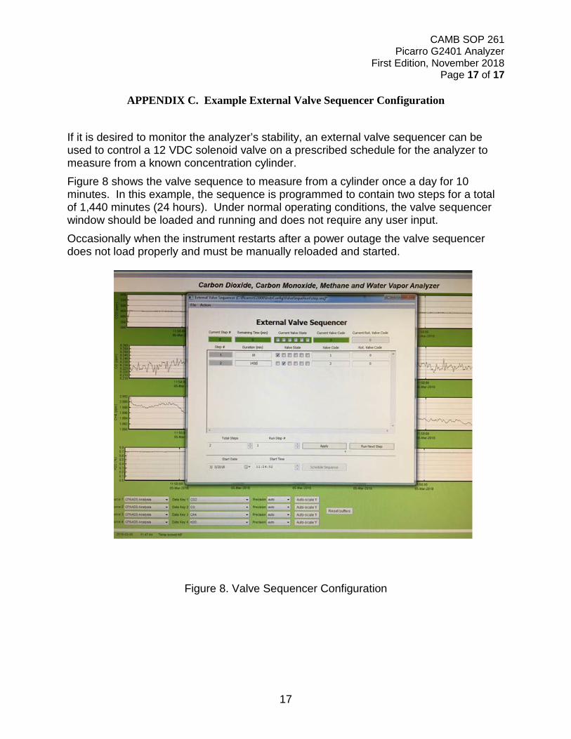
APPENDIX C. Example External Valve Sequencer Configuration If it is desired to monitor the analyzer’s stability, an external valve sequencer can be used to control a 12 VDC solenoid valve on a prescribed schedule for the analyzer to measure from a known concentration cylinder. Figure 8 shows the valve sequence to measure from a cylinder once a day for 10 minutes. In this example, the sequence is programmed to contain two steps for a total of 1,440 minutes (24 hours). Under normal operating conditions, the valve sequencer window should be loaded and running and does not require any user input. Occasionally when the instrument restarts after a power outage the valve sequencer does not load properly and must be manually reloaded and started.
Figure 8. Valve Sequencer Configuration