community development department lighting district ... · 7000 florida street punta gorda, florida...
TRANSCRIPT

Community Development Department Lighting District ____________
Supplemental Specifications for
Roadway Lighting Systems
December 2011
7000 Florida Street Punta Gorda, Florida 33950
Tele: 941.575.3632 Fax: 941.575.3664
www.charlottecountyfl.com/CommunityDevelopment/Engineering

ROADWAY LIGHTING SYSTEMS Purpose Workmanship General Requirements Concealed Work Supplemental Surface Treatments
Permatex Anti-Seize Lubricant Noalox Anti-Oxidant Compound
Conduit Schedule 40 Rigid PVC Nonmetallic Conduit Deep Bell Ends Special Long Line Couplings Grounding
Ground Clamp Pull Boxes Quazite, Part #PG1324BA12 Quazite, Part #PG1324HA_ _ Quazite, Part #PG1730BA12 Quazite, Part #PG1730HA_ _ Wire Service Point Detail
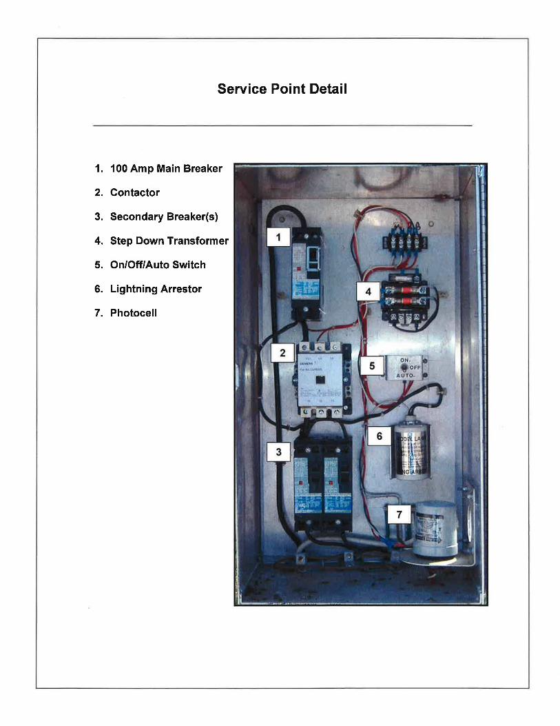
Service Point Detail Load Center Cabinet Enclosure Contactor
Siemens, Part #LEN00E003120A Circuit Breakers
Siemens Molded Case Circuit Breakers Step-Down Transformer
Square D, Part #9070TF100D1 Lightning Arresters
Delta, Part #LA601 Square D, Part #SDSA3650 DITEK, Part #DTK-DL480 Solderless Lug
Poles and Luminaires General Electric M-400A, MDCL General Electric M-400A, MDRL General Electric Turnpike, RPFS
Directional Bore and Driveway Crossings Couplings
Miscellaneous Intermatic, Part #K4521 Bussman Fuseholders FNQ-10 Fuses

CHARLOTTE COUNTY LIGHTING DISTRICT
SUPPLEMENTAL SPECIFICATIONS FOR ROADWAY LIGHTING SYSTEMS
PURPOSE: All work associated with the installation of a roadway lighting system shall conform to current Florida Department of Transportation (FDOT) Design Standards, Standard Specifications for Road and Bridge Construction, AASHTO Roadway Lighting Design Guide, the National Electrical Code (NEC) and/or the National Electric Safety Code (NESC), and this supplement. If a contradiction in code arises between the NEC and the NESC, the NESC shall be the governing document. It is the intent of this supplement to detail installation requirements, dictated by the County, which exceed FDOT standards and NEC requirements. It is the contractor’s responsibility to note these extended specifications and to adhere to the methods and requirements mandated in this document. WORKMANSHIP: All work is to be performed in a workmanlike manner. It is the contractor’s responsibility to provide labor, skilled in the appropriate areas, necessary to provide an acceptable and professional finished product. The contractor and his personnel shall have, at all times, all the necessary paperwork needed to complete the job. It is expected that plumb surfaces shall be plumb. Spacing of multiple components, such as conduit stubs or straps, shall be in equal increments. All materials shall be new or in like-new condition. All light pole assemblies and the electrical service pole shall be leveled to the satisfaction of the Lighting District inspector. The Charlotte County Lighting District inspector assigned to the project shall have the authority to make final determinations on whether workmanship, materials, and/or final product(s) meet the specifications contained herein. GENERAL REQUIREMENTS: During all working hours, the contractor shall have a responsible, English-speaking superintendent on the project with the capabilities and authority required by FDOT Specifications, Section 5-8. All roadway lighting systems shall utilize 480 volt, single phase. The voltage is distributed with one current-carrying conductor, one grounded conductor, and one grounding conductor. Under no circumstances shall the neutral be switched, fused, or broken in any manner. The light type for all lighting systems shall be high pressure sodium (HPS). There will be no substitutes. Designers shall utilize any combination of 250 or 400 watt HPS lamps.

All conduits entering or exiting the load center cabinet shall use a Myers hub. All conduits shall have a minimum of two straps. Appropriate straps to secure rigid metal pipes are conduit hangers (Mineralac strap), one-hole heavy wall rigid straps, or a channel system (i.e., Kindorf, GS Metals, B-Line, etc.) No nails or small screws shall be used to mount cabinet, straps, etc., in place. All fastening devices shall be galvanized or stainless steel screws, sleeve anchors, or lag bolts, 5/16" x 2" or larger. The contractor shall submit cut sheets on all materials proposed for the installation of the roadway lighting system. The material submittal will be reviewed by the Charlotte County Lighting District for conformance. The electrical load center cabinet shall be installed onto a 26’ concrete service pole for overhead services or onto a 12' concrete pole for underground services. For all underground services, the contractor will be responsible to pay the Florida Power and Light tariff required to supply the load center with power. Contractors will not be permitted to install conduit risers onto FPL poles to circumvent the FPL tariff. All lighting load centers are to be metered. The contractor shall furnish and install an oval eye bolt thru the top of the 26’ service pole for FPL to attach onto. Each new lighting load center will utilize a Millsbank by-pass meter socket, part #U3505-XL-TG-HSP along with a 100 amp, Square D, non-fusible safety switch, part #HU363RB. Each lighting branch circuit shall have its own conduit run. Installing two lighting circuits into one conduit is unacceptable. The Engineer of Record should make every effort possible to locate the roadway lighting load center in the middle of the circuits. Each light pole shall have a pull box placed directly in front of or behind the light pole foundation. The connection between the pull box and the street light base shall be by means of seal tight conduit. All lighting circuits shall be designed to use only #6 AWG, THHN/THWN stranded wire throughout the system. If the required circuits cannot be accomplished using #6 AWG, an additional load center will be required. CONCEALED WORK: Work which will not be readily visible upon completion shall not be concealed until a County Lighting inspector gives approval. In the event the items listed below are concealed, it will be the contractor’s responsibility to expose the questioned item(s) for the inspector’s approval, at no additional cost to the County. This includes, but is not limited to: * Buried or imbedded conduit * Ground wire, rods, and arrays * All Meg ohm and continuity testing shall be done in the presence of the
County inspector

SUPPLEMENTAL SURFACE TREATMENTS: The application of the following materials to various components shall be performed during assembly:
• Threaded Hardware - All non-electrical threaded hardware (i.e., all threaded pole hardware or any other threaded component which requires assembly) shall be coated with Ideal Noalox Anti-Oxidant Compound or County-approved equivalent. No spray-on, anti-seize compound will be accepted. The amount of Noalox applied shall be sufficient to be visible.
• Electrical Connections - All mechanical electrical connections shall have the various components of the splice or termination coated with an oxide inhibitor.
CONDUIT: All conduit and fittings shall be utilized for the purpose they were designed. There shall be no fabrications of non-standard sweeps by "cutting up" a standard sweep. Heat bending PVC conduit is acceptable. No conduit shall be filled beyond the capacity stated in the National Electrical Code. PVC conduit stubs into the load center cabinet shall be plumb and evenly distributed. All PVC conduits shall be electrical grade 2” schedule 40 minimum. All PVC conduits shall be joined together with integral, deep bell ends and special long line couplings. Charlotte County reserves the right to redirect the termination point(s) of any or all conduit(s) from what is shown on the plans. If the quantity of materials is increased, the contractor shall be compensated according to the per unit price of this change. All exposed, aboveground conduit shall be heavy-wall galvanized rigid conduit. All threaded rigid conduit connections shall be coated with an anti-seize lubricant. The exposed, aboveground conduit shall be properly grounded at any location in the lighting system. All conduit ends inside a pull box shall be sufficiently notched to allow a PVC plumbing test cap to be installed fully onto the conduit. The conduits inside the pole base shall be sealed with duct seal putty. All lighting conduits shall be placed between 30” and 36” deep. If conduits cannot be placed at a 30” minimum depth due to underground conflicts (i.e., rocks, roots, culvert pipes, etc.), the Contractor shall furnish and install 2” rigid conduit in those areas, and it shall be grounded per National Electric Code (NEC) Specifications. GROUNDING: The minimum size of all ground/bond wire will be #6 AWG stranded, green wire. The wire insulation shall be THHN/THWN. Bare wire will not be accepted inside conduit. The grounding wire shall attach to the ground rod by means of a grounding acorn with a hex bolt. Multiple conductors shall not be joined together under a grounding acorn. One conductor shall be terminated under the acorn, and all others shall be joined with a split bolt. Under no circumstance will Cadweld heat fusion welding be acceptable.
All exposed, aboveground metal conduit shall be properly grounded with a ground bushing clamp or Myers hub. All ground rods shall be sectional, 5/8" x 10', copper clad, bonded to a steel core. Forty (40) feet shall be installed at the load center and twenty (20) at all light pole locations. PULL BOXES: All pull boxes shall be traffic-rated (20K minimum), fiberglass-reinforced concrete, such as "Quazite-Composolite," Part #PG1324BA12 (box), and #PG1324HA_ _ (lid). Dashes indicate lid logo. Pull boxes placed in front of the load center and on the opposite side of the service point road crossing shall be larger than the standard lighting pull box. Stacking of pull boxes will not be permitted. The box to be used at the load center and load center crossing shall be a Quazite part #PG173OBA12 (box) and #PG173OHA_ _ (lid). The last two digits left blank are for the lid logo and shall be filled in by the contractor for the specific lid logo required. All pull boxes shall have cover logos identifying their specific purpose. The lid logo shall read “Street Lighting.” The pull boxes shall have the FDOT APL number embossed in the cover, and the interior of the box shall be stenciled with the APL number. Placement shall be in accordance with FDOT Design Standards, however, preference is to locate pull boxes in sidewalk areas if job conditions permit. All pull boxes shall have a concrete pad poured around them per FDOT Design Standards Index Number 17500, Sheet 2 of 3. Charlotte County reserves the right to add to or delete from the overall quantity of pull boxes from what is shown on the plans. If the quantity of materials is increased, the contractor shall be compensated according to the per unit price of this change. WIRE: All current-carrying conductors shall have continuous black THHN/THWN insulation, rated at 600 volts. All grounded conductors shall have continuous white THHN/THWN insulation, rated at 600 volts. All grounding conductors shall have continuous green THHN/THWN insulation, rated at 600 volts. There shall be no splices in the conductors at any point within the system. All pole riser wire shall be #10 AWG, THHN/THWN stranded. No solid wire will be accepted. The insulation colors of riser wires shall be black, white, and green. SERVICE POINT DETAIL: A photograph of the service point is provided within this document. The detail depicts how the components within the cabinet should be laid out. The electrical service conductors shall be #2 AWG with continuous black and white THHN/THWN insulation. The minimum size wire connecting the main breaker to the contactor and the contactor to the secondary breaker(s) shall be #6 AWG stranded, THHN/THWN wire. The minimum size of any control wire shall be #14 AWG stranded, THHN/THWN wire.

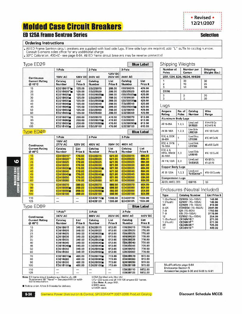
LOAD CENTER CABINET ENCLOSURE: The load center cabinet shall be manufactured by Suncoast Metal Fabricators, located at 1030 South 86th Street, Tampa, Florida (phone 813-630-2800). The cabinet shall be constructed of aluminum and utilize a sub-treasury lock. Cabinet dimensions are 15"W x 29"H x 12"D, part #SMF-2. A 2” hole, covered with Plexiglas, shall be installed in the lower right corner of the load center cabinet. If the contractor chooses to buy all the components which make up the load center individually and assemble them on site, it is recommended that Charlotte County perform the assembly work. Charlotte County will assemble the supplied materials, wire, and test the back panel, and the contractor will install it into the cabinet. CONTACTOR: The contactor shall be an electrically held heating/lighting contactor, as manufactured by Siemens, part #LEN00E003120A. The contactor shall be 3-pole, rated for 100 amps, and utilize a 120 volt coil. CIRCUIT BREAKERS: The main circuit breaker shall be a 100 amp, 2-pole, 480 volt, molded case circuit breaker, as manufactured by Siemens, part #ED42B100. Secondary breakers shall be rated for the appropriate amperes, as specified in the plans. The secondary circuit breakers shall be the appropriate amperage, 2-pole, 480 volt, molded case circuit breakers, as manufactured by Siemens, part #ED42B_ _ _ (blank spaces indicate proper amperes, as required). STEP-DOWN TRANSFORMER: The contactor shall be equipped with a step-down transformer to operate the contactor coil and photocell circuit. The step-down transformer shall have a 480 volt input and a 120 volt output, with primary and secondary fusing, as manufactured by Square D, part #9070TF100D1. LIGHTNING ARRESTERS: The load center shall have a hard-wired secondary surge arrester wired to the load side of the main circuit breaker. The lightning arrester shall be rated at 600 volt, as manufactured by Delta, part #LA601, or Square D, part #SDSA3650. Each light pole shall have a lightning arrester inside the pole hand hole or within the pole transformer base. The lightning arrester shall be rated up to 600 volt, single-phase, as manufactured by DITEK, part #DTK-DL480. The grounding conductor shall be attached to the pole and service ground by means of a solderless lug, sized appropriately. POLES AND LUMINAIRES: Whenever a lighting system is designed, the engineer of record shall use poles or pole arm configurations which allow the fixture(s) to be mounted at a height of 30’, 40’, or 45’ above the roadway. For lighting systems which utilize turnpike-style fixtures, the engineer of record shall specify on the plan sheet(s) the desired degree of tilt.

All lighting fixtures shall be manufactured by General Electric. All lighting systems shall utilize any combination of the following lighting fixtures: General Electric M-400A, MDCL, 250 or 400 watt HPS General Electric M-400A, MDRL, 250 or 400 watt HPS General Electric Turnpike, RPFS, 250 or 400 watt HPS All roadway lighting systems shall utilize steel screw bases in lieu of concrete foundations. If an aerially-fed lighting system is being used, each pole shall have a lightning arrester and fuseholder located inside a weatherproof junction box, sized accordingly. The metal arm on the pole shall be grounded. The wires which feed the lights on each pole shall be an IMSA Beldon-type cable, spec #50-2. The poles at each end of the pole line shall be back-guyed and have the proper protective skirts installed. If an aerial-fed lighting system is being used, it shall have three insulated conductors between each pole, supported by a bare wire. The third conductor will be the equipment ground. DIRECTIONAL BORE AND DRIVEWAY CROSSINGS: All road crossings shall be accomplished by means of a directional bore. The contractor shall provide Charlotte County with directional bore log(s) taken at 10’ intervals for all directional bores. Conduit for the purpose of roadway lighting that will be installed by means of a directional drill shall be 2” continuous HDPE, SDR11, colored gray pipe. The contractor shall provide the appropriate manufacturer fittings when switching from the continuous conduit to standard PVC. Examples of appropriate couplings are Etco brand Elock couplings, part #EL237 or Electroweld. Before the directional bore begins, the contractor shall expose all underground facilities. The contractor will be responsible for cleaning up the spoil and returning the site back to the original condition after the bore operation is complete. All drainage facilities shall be properly protected (i.e., hay bales, silt fence, etc.) from directional bore spoil. In the event that drainage facilities become filled with spoil as a result of the directional bore, it shall be the contractor’s responsibility to have the material removed and the facility returned to its original condition. The depth of any directionally-drilled conduit shall not exceed 10’. Charlotte County reserves the right to reject any conduit(s) placed greater than 10’ deep. Should a depth greater than 10’ be required, the contractor shall obtain approval from Charlotte County prior to performing the work. MISCELLANEOUS: The hand/off/auto functions of the load center shall be controlled by means of a control station, as manufactured by Square D, part number 9001KYK111. The photo cell shall be a twist lock style, 120 vac., as manufactured by Intermatic, part #K4521.

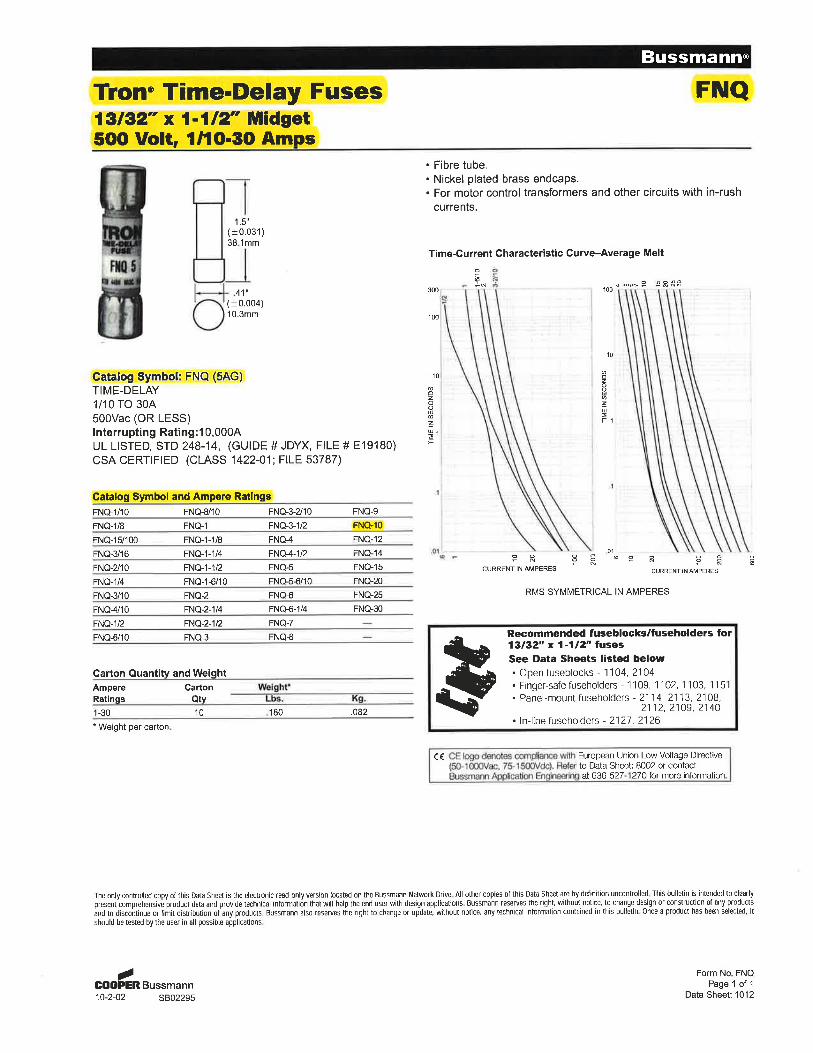
Inside the pole hand hole or inside the pole’s transformer base, each pole shall have a weatherproof fuseholder. The fuseholder shall be manufactured by Bussman, parts #HEB-AW-RYC and #HET-AW-RYC. The HET-AW-RYC fuseholder shall contain a permanently installed solid slug. No substitutes will be accepted. FNQ-10 fuses shall be used at all pole locations.