compact - amazon s3
TRANSCRIPT

SENS EnerGenius® DC Compact Technical Manual
1
SENS Part Number: 101334 Document Revision: C DCN Number: 108130 Date: October 21, 2021
PATENTED US 9,270,140; 9,385,556; 9,413,186; 9,509,164; 9,466,995; 9,948,125; 10,575,433
Installation or service questions? Call SENS between 8 a.m. and 5 p.m. (Mountain Time), Monday through Friday, or visit our website.
Copyright © Stored Energy Systems LLC 2020 The SENS name / logo, EnerGenius, HELIX, and Dynamic Boost are trademarks of Stored Energy Systems LLC
Installation & Operation Manual
COMPACT Automatic Battery Charger/Power Supply
1840 Industrial Circle Longmont, CO 80501 Phone: 303.678.7500 800.742.2326 Fax: 303.678.7504 Email: [email protected] Web: www.sens-usa.com
SENS EnerGenius® DC Compact Technical Manual
2
TABLE OF CONTENTS 1 IMPORTANT SAFETY INSTRUCTIONS FOR INSTALLER AND OPERATOR ............................................................ 4 2 MODEL NUMBER BREAKOUT .............................................................................................................................. 6 3 PERFORMANCE SPECIFICATIONS ........................................................................................................................ 7 4 SYSTEM OVERVIEW ........................................................................................................................................... 10
4.1. Physical Overview .................................................................................................................................... 10 4.2. Functional Overview ................................................................................................................................ 11
5 MOUNTING INSTRUCTIONS .............................................................................................................................. 12 5.1. Mounting Location ................................................................................................................................... 12 5.2. Mounting Instructions .............................................................................................................................. 12
6 SETUP AND WIRING .......................................................................................................................................... 13 6.1. Wire Ratings and Sizes ............................................................................................................................. 13 6.2. Grounding Instructions and Connection .................................................................................................. 15 6.3. DC Connection .......................................................................................................................................... 15 6.4. AC Connection .......................................................................................................................................... 15 6.5. Standard Alarm Connections ................................................................................................................... 16 6.6. Optional High Current Relay Connections ............................................................................................... 17 6.7. CANbus and RS-485 Connections ............................................................................................................. 18 6.8. Ethernet ................................................................................................................................................... 20 6.9. SENSbus Connection ................................................................................................................................ 21 6.10. Verify Connections ................................................................................................................................... 22
7 START-UP PROCEDURE ..................................................................................................................................... 23 7.1. Connect Battery/Outputs ......................................................................................................................... 23 7.2. Verify Configuration ................................................................................................................................. 23 7.3. Apply AC Input Voltage ............................................................................................................................ 24 7.4. Power Off ................................................................................................................................................. 24
8 ALARMS, LEDS AND DISPLAY ............................................................................................................................ 25 8.1. LED Indicators........................................................................................................................................... 25 8.2. Individual Alarm Relay Contacts............................................................................................................... 25 8.3. LCD Panel ................................................................................................................................................. 26 8.4. Latched Alarms ......................................................................................................................................... 26 8.5. Alarm Definitions ..................................................................................................................................... 26
9 OPERATION ....................................................................................................................................................... 33 9.1. Charging Algorithms ................................................................................................................................. 33 9.2. Float Mode ............................................................................................................................................... 33 9.3. Dynamic Boost™ Mode ............................................................................................................................ 33 9.4. HELIX Mode .............................................................................................................................................. 34 9.5. Charging Low or Zero-volt Batteries ........................................................................................................ 34 9.6. Commissioning Batteries .......................................................................................................................... 35 9.7. Battery Check ........................................................................................................................................... 35 9.8. Restore Factory Defaults .......................................................................................................................... 35 9.9. Keypad Operation .................................................................................................................................... 36 9.9.3. Menu Options .......................................................................................................................................... 36 9.10. Configuration and Monitoring with SENS Setup Utility ........................................................................... 41 9.11. Protocol Communications Circuit Board .................................................................................................. 41 9.12. Temperature Compensation .................................................................................................................... 43 9.13. Load Share Charger Operation ................................................................................................................. 43 9.14. Remote Alarm/Communications Panel Accessory ................................................................................... 44 9.15. Efficiency .................................................................................................................................................. 44
10 SERVICE AND MAINTENANCE ........................................................................................................................... 45 10.1. Recommended Annual Maintenance....................................................................................................... 45 10.2. Air Filter .................................................................................................................................................... 45 10.3. Fans .......................................................................................................................................................... 45 10.4. Supplemental Surge Protectors ............................................................................................................... 45
11 MODBUS COMMUNICATIONS .......................................................................................................................... 46

SENS EnerGenius® DC Compact Technical Manual
3
11.1. TCP/IP Modbus—Optional ....................................................................................................................... 46 11.2. Modbus RS-485—Optional ....................................................................................................................... 46 11.3. Modbus Holding Registers ....................................................................................................................... 46 11.4. Basic Charging Alarms Bit Definition ........................................................................................................ 48 11.5. Charging Status Bit Definition .................................................................................................................. 49 11.6. Charging Alarms Extended Bit Definition ................................................................................................. 49 11.7. Charging AC Alarms Bit Definition ............................................................................................................ 50 11.8. Accessory Channel Alarms Bit Definition ................................................................................................. 50 11.9. Accessory System Alarms Bit Definition ................................................................................................... 50 11.10. Accessory Assigned Channel Alarms Bit Definition .................................................................................. 51 11.11. Writable Control Flags (Coils) ................................................................................................................... 51
12 TROUBLESHOOTING/ERROR CODES ................................................................................................................. 52 12.1. Configuration Error Codes ........................................................................................................................ 52 12.2. Troubleshooting ....................................................................................................................................... 56
13 GLOSSARY .......................................................................................................................................................... 62

SENS EnerGenius® DC Compact Technical Manual
4
1 IMPORTANT SAFETY INSTRUCTIONS FOR INSTALLER AND OPERATOR 1.1. SAVE THESE INSTRUCTIONS – This manual contains important safety and operating instructions for
EnerGenius DC compact battery chargers.
1.2. Before using battery charger, read all instructions and cautionary markings on battery charger, battery, and product using battery.
1.3. Do not expose charger to rain or snow.
1.4. Use of an attachment not recommended or sold by the battery charger manufacturer may result in a risk of fire, electric shock, or injury to persons.
1.5. This charger is intended for commercial and industrial use. ONLY TRAINED AND QUALIFIED PERSONNEL MAY INSTALL AND SERVICE THIS UNIT.
1.6. Do not operate charger if it has received a sharp blow, been dropped, or otherwise damaged in any way; shut off power at the branch circuit protectors and have the unit serviced or replaced by qualified personnel.
1.7. To reduce risk of electric shock, disconnect the branch circuit feeding the charger before attempting any maintenance or cleaning. Turning off controls will not reduce this risk.
1.8. Use appropriate lockout / tagout procedures to ensure safety of all personnel installing and servicing this equipment. The input and output breakers are equipped with provision to lock breakers in the OFF position.
1.9. WARNING – RISK OF EXPLOSIVE GASES
1.9.1. WORKING IN THE VICINITY OF A LEAD-ACID OR NICKEL-CADMIUM BATTERY IS DANGEROUS. STORAGE BATTERIES GENERATE EXPLOSIVE GASES DURING NORMAL BATTERY OPERATION. FOR THIS REASON, IT IS OF UTMOST IMPORTANCE THAT YOU READ THIS MANUAL AND FOLLOW THE INSTRUCTIONS EACH TIME YOU USE THE CHARGER.
1.9.2. To reduce the risk of battery explosion, follow these instructions and those published by the battery manufacturer and the manufacturer of any equipment you intend to use in the vicinity of a battery. Review cautionary markings on these products and on the engine.
1.10. PERSONAL PRECAUTIONS
1.10.1. Someone should be within range of your voice or close enough to come to your aid when you work near a storage battery.
1.10.2. Have plenty of fresh water and soap nearby in case battery electrolyte contacts skin, clothing, or eyes.
1.10.3. Wear complete eye protection and clothing protection. Avoid touching eyes while working near a storage battery.
1.10.4. If battery electrolyte contacts skin or clothing, wash immediately with soap and water. If electrolyte enters eye, immediately flood the eye with running cold water for at least 10 minutes and get medical attention immediately.
1.10.5. NEVER smoke or allow a spark or flame in vicinity of battery or engine.
1.10.6. Be extra cautious to reduce risk of dropping a metal tool onto the battery. It might spark or short circuit the battery or another electrical part that may cause explosion. Using insulated tools reduces this risk but will not eliminate it.
1.10.7. Remove personal metal items such as rings, bracelets, necklaces, and watches when working with a storage battery. A storage battery can produce a short circuit current high enough to weld a ring or the like to metal, causing a severe burn.

SENS EnerGenius® DC Compact Technical Manual
5
1.10.8. When charging batteries, charge LEAD-ACID or LIQUID ELECTROLYTE NICKEL-CADMIUM batteries only. Consult SENS before using with any other type of battery - other batteries may burst and cause injuries to persons and damage to property. NEVER charge a frozen battery.
1.10.9. Consult national and local ordinances to determine if additional battery fault protection is necessary in your installation.
1.11. Preparing Battery For Charge
1.11.1. Be sure area around battery is well ventilated while battery is being charged.
1.11.2. Ensure battery terminals are clean and properly tightened. Be careful to keep corrosion from coming in contact with eyes.
1.11.3. Add distilled water in each cell until battery acid reaches level specified by battery manufacturer. Do not overfill. For a battery without removable cell caps, such as valve regulated lead acid batteries, carefully follow manufacturer’s recharging instructions.
1.11.4. Study all battery manufacturer specific precautions such as removing or not removing cell caps while charging and recommended rate of charge. The recommended charge current range must include the rated output current of the charger.
1.12. Charger Location
1.12.1. Locate the charger as far away from the battery as DC cables permit.
1.12.2. Never place the charger directly above or below the battery being charged; gases from the battery will corrode and damage charger.
1.12.3. Never allow battery acid to drip on charger when reading electrolyte specific gravity or filling battery.
1.12.4. Do not operate charger in a closed-in area or restrict ventilation in any way.
1.12.5. Do not set anything on top of the charger.

SENS EnerGenius® DC Compact Technical Manual
6
2 MODEL NUMBER BREAKOUT
D S - F - 120 - 050 - A 0 A - 0 00
A B - C - E - G - K L M - N P
Parameter Code Value
A Product Family D EnerGenius DC
B Enclosure Type S Compact
C AC Input Voltage F Three Phase - 480VAC
E DC Output Voltage 120 120 VDC
240 240 VDC
G Output Current
120 VDC 240VDC
006 6A
012 12A
025 25A
035 35A
050 50A
K Comm and Display A
Standard - (LCD, Keypad, 5 Form-C Relays, Ethernet)
L Accessory Hardware 0 None
A High Current AC Alarm Relays (2X 120VAC, 5A)
M Surge Protection A Standard Surge Protection
B Supplemental AC/DC Surge Protection
N Mounting 0 Wall mount
1 Portable
P Configuration
00 Standard Configuration
01 PIP Compliant (requires Accessory Hardware selection A)
## Factory specified custom configuration

SENS EnerGenius® DC Compact Technical Manual
7
3 PERFORMANCE SPECIFICATIONS
EnerGenius® DC is a high power industrial/utility class 3-phase switchmode battery charger/power supply, specially hardened for use in harsh industrial environments. Advanced technology switch mode power conversion is significantly smaller & lighter than conventional line frequency (e.g. SCR) power conversion and, even without a battery connected, delivers lower output ripple and much faster dynamic response.
Forced ConductionTM cooling keeps the high efficiency power electronics free of dust and dirt, making EnerGenius DC well-suited for operation in industrial, utility, power plant, and other harsh environments. Two variable speed, premium ball-bearing fans cool each rectifier. Rectifiers maintain nearly full output capability even if one fan fails. A fan failure alarm system with local and remote indication enables service dispatch while the second fan continues to run. The fan module is easily replaced in the field with common tools.
5 Standard Form C contact alarms are factory set and field reconfigurable, with indication via communication port, front panel LCD and assignable alarm relays. Two additional high current AC alarm relays are optional.
Options include supplemental surge suppression, and data communication including Modbus, DNP3 and IEC 61850. Chargers can be equipped with one or multiple communication protocols. Specifications are detailed in the table below, see following sections for installation and operation instructions.
Table 1 – Specifications
AC Input Voltage, frequency Full output power: 358-528 VAC 3-phase line to line, 50% power limit from 188-357 VAC. AC line to ground voltage limited to 277VAC. 47-63 Hz.
Input current 12A maximum at 358VAC for maximum configured unit.
Overcurrent protection
3-pole UL 489 listed circuit breaker
10 kAIC, lockable
Loss of phase Continues operating with current limit reduced to 50%
AC transient protection
Layered electrical transient defenses. Optional UL 1449 Type 1 Listed supplemental surge protection, alarmed and with field replaceable elements, surge capacity rated 75kA 8/20 µs; visual and remote indications.
Loss of phase Continues operating with current limit reduced to 50%
Efficiency Up to 95%, see section 9.14
Power Factor and Total Harmonic Distortion
>.98 typical at maximum rated load current and boost charge voltage. Total Harmonic Distortion <3%
DC Output Voltage 120 VDC or 240 VDC nominal. 120 VDC: output adjustable from 8-160V. 240 VDC: output adjustable from 16-320V. If AC voltage is not applied, charger powers down below 60 VDC.
Current Output limit: 7kW or 50A for 120VDC models whichever is less, or 7kW or 25A for 240VDC models, whichever is less
Soft Start System gradually increases current output from zero with a maximum of 5 seconds to full required output
Charging modes Multi-stage, including float, boost, HELIX, and commissioning charge modes
Current limit 100% current capability subject to temperature limits and AC voltage limits; field adjustable to max rated current.
Charging characteristic
Constant voltage, current limited; patented Dynamic Boost and HELIX control
Line & load regulation ±0.5%
Output Ripple < 30 mV with battery, <100mV off-battery for 120VDC, <200mV off-battery for 240VDC. Delivers fast-responding, stable, well-filtered DC without battery.

SENS EnerGenius® DC Compact Technical Manual
8
Step response 8ms typical without battery, to recover within 1% of rated output voltage from load step change of 50% rated output current
Output protection Electronic current limit. 2-pole UL 489 listed circuit breaker.
10 kAIC, lockable
DC surge protection Layered electrical transient defenses. Optional UL1449 Open Type 2 Listed supplemental surge protection, alarmed and with field replaceable elements, surge capacity rated 75kA 8/20 µs; visual and remote indications.
Battery types Flooded lead-acid, AGM, Ni-Cd, VRLA, and lithium
DC power supply operation
Delivers fast-responding, stable, well-filtered DC without battery
Battery temp. compensation
Standard. On-board sensor modifies output voltage when temperature is between 0°C and+40°C. Slope adjustable, factory set to – 0.18% per degree C. Optional remote battery monitor provides battery temperature probe.
Dead battery charge Starts into and recharges zero-volt battery
Parallel/load share operation
Two or more independent chargers actively current share and synchronize all modes for increased current or fault tolerance, requires load share accessory kit (SENS p/n 209069)
Output blocking protection
Prevents sparking during battery connection; serves as an "OR" diode to isolate a non-functioning charger from others in a redundant charger configuration
Output Derating
Input Voltage/# Phases
% Output Power
Available
Max. Available Output Current*
140VDC 60VDC 30VDC
400-480VAC/3-ph Full Rating
(7kW) 50A 50A 50A
400-480VAC/1-ph 50% (3.5kW) 25A 50A 50A
208-240VAC/3-ph 50% (3.5kW) 25A 50A 50A
208-277VAC/1-ph 25% (1.75kW) 12.5A 29A 50A
*120V-50A model shown, divide current values in half for 240V-25A model
Adjustment & Controls
Charge mode control Fully automatic patented Dynamic Boost system. Manual boost, timed boost & battery commissioning charging options are available from front panel control.
Front panel control Change all parameters including voltages, current limits, alarm parameters, relay assignments, network configurations, time-outs, and more
Local computer Change all parameters, troubleshoot, create/save configuration files for quick download to chargers using network connection and SENS Setup Utility software available at www.sens-usa.com
Status Reporting
LEDs Two multi-color front panel status LEDs
Metering AC/DC Voltmeter accurate to ±1%; AC/DC ammeter to ±1%; AC frequency meter to ±1.5%; DC Output Watts; DC Output as a percent of maximum rated output
Status display 20-character display of status & alarm messages.
Data logging Data logging to internal nonvolatile memory, based on events and at fixed times. Logs retrieved using computer network connection.
Alarms Alarm Outputs Factory set, field reconfigurable, latching or non-latching. Alarms available via communication port, alarm relays, and on front panel display.
SENS EnerGenius® DC Compact Technical Manual
9
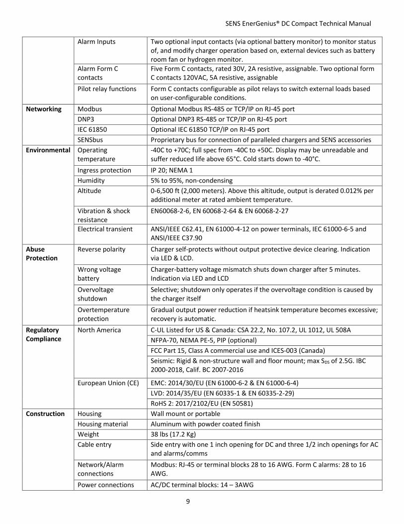
Alarm Inputs Two optional input contacts (via optional battery monitor) to monitor status of, and modify charger operation based on, external devices such as battery room fan or hydrogen monitor.
Alarm Form C contacts
Five Form C contacts, rated 30V, 2A resistive, assignable. Two optional form C contacts 120VAC, 5A resistive, assignable
Pilot relay functions Form C contacts configurable as pilot relays to switch external loads based on user-configurable conditions.
Networking Modbus Optional Modbus RS-485 or TCP/IP on RJ-45 port
DNP3 Optional DNP3 RS-485 or TCP/IP on RJ-45 port
IEC 61850 Optional IEC 61850 TCP/IP on RJ-45 port
SENSbus Proprietary bus for connection of paralleled chargers and SENS accessories
Environmental Operating temperature
-40C to +70C; full spec from -40C to +50C. Display may be unreadable and suffer reduced life above 65°C. Cold starts down to -40°C.
Ingress protection IP 20; NEMA 1
Humidity 5% to 95%, non-condensing
Altitude 0-6,500 ft (2,000 meters). Above this altitude, output is derated 0.012% per additional meter at rated ambient temperature.
Vibration & shock resistance
EN60068-2-6, EN 60068-2-64 & EN 60068-2-27
Electrical transient ANSI/IEEE C62.41, EN 61000-4-12 on power terminals, IEC 61000-6-5 and ANSI/IEEE C37.90
Abuse Protection
Reverse polarity Charger self-protects without output protective device clearing. Indication via LED & LCD.
Wrong voltage battery
Charger-battery voltage mismatch shuts down charger after 5 minutes. Indication via LED and LCD
Overvoltage shutdown
Selective; shutdown only operates if the overvoltage condition is caused by the charger itself
Overtemperature protection
Gradual output power reduction if heatsink temperature becomes excessive; recovery is automatic.
Regulatory Compliance
North America C-UL Listed for US & Canada: CSA 22.2, No. 107.2, UL 1012, UL 508A
NFPA-70, NEMA PE-5, PIP (optional)
FCC Part 15, Class A commercial use and ICES-003 (Canada)
Seismic: Rigid & non-structure wall and floor mount; max SDS of 2.5G. IBC 2000-2018, Calif. BC 2007-2016
European Union (CE) EMC: 2014/30/EU (EN 61000-6-2 & EN 61000-6-4)
LVD: 2014/35/EU (EN 60335-1 & EN 60335-2-29)
RoHS 2: 2017/2102/EU (EN 50581)
Construction Housing Wall mount or portable
Housing material Aluminum with powder coated finish
Weight 38 lbs (17.2 Kg)
Cable entry Side entry with one 1 inch opening for DC and three 1/2 inch openings for AC and alarms/comms
Network/Alarm connections
Modbus: RJ-45 or terminal blocks 28 to 16 AWG. Form C alarms: 28 to 16 AWG.
Power connections AC/DC terminal blocks: 14 – 3AWG
SENS EnerGenius® DC Compact Technical Manual
10
4 SYSTEM OVERVIEW
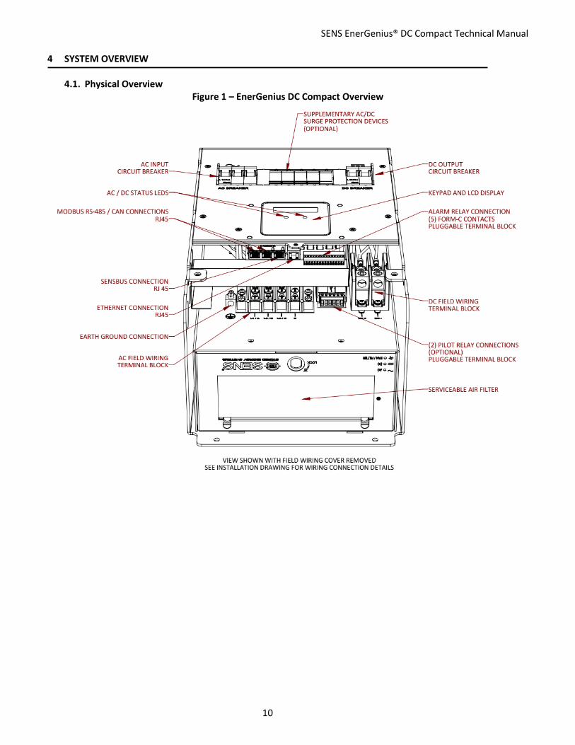
4.1. Physical Overview Figure 1 – EnerGenius DC Compact Overview

SENS EnerGenius® DC Compact Technical Manual
11
4.2. Functional Overview 4.2.1. Configuration
Each EnerGenius DC Compact System comes factory configured for its application from the factory. Configuration details are given on the configuration label (see Figure 2). These values are assigned according to the profile configuration selected during the customer order. Profiles are available for various battery types and applications. Some of the available configuration options may not be applicable to a given installation. Adjustments to settings can be made via the front panel keypad or the SENS Setup Utility software via ethernet connection of the EnerGenius DC Compact unit to a computer.
Figure 2 –Configuration Label (on inside lower cover)
4.2.2. Standard Items 4.2.2.1. AC Input Breaker, UL 489 listed. The breaker is lockable in the OFF position.
4.2.2.2. DC Output Breaker, UL 489 listed breaker. The breaker is lockable in the OFF position.
4.2.2.3. 5 Form C Relays Contacts for Alarm Relays
4.2.2.4. Ethernet communications
4.2.2.5. SENSbus communications
4.2.3. Factory Optional Items 4.2.3.1. Supplementary Surge Protectors
Supplementary Surge Protectors provide additional AC and DC protection in surge intensive environments. These protectors are equipped with field-replaceable modules that can be replaced when the surge protective device needs replacement. Alarm and status information of the surge protective devices is included.
4.2.3.2. High Current Relays Two high current Form C relay contacts available for alarms. Configurable using the SENS Setup Utility.
4.2.3.3. Software Optional communication protocols include Modbus (TCP/IP and RS-485), DNP3 (TCP/IP and RS-485) and IEC 601850.

SENS EnerGenius® DC Compact Technical Manual
12
5 MOUNTING INSTRUCTIONS
INSTALLATION OF THE UNIT MUST COMPLY WITH LOCAL ELECTRICAL CODES AND OTHER APPLICABLE INSTALLATION CODES AND BE MADE ACCORDING TO THE INSTALLATION INSTRUCTIONS AND ALL APPLICABLE SAFETY REGULATIONS.
Printed circuit boards contain static sensitive components. Damage can occur even when static levels are too low to produce a noticeable discharge shock. To avoid static discharge damage, handle the charger by the chassis only. Remove the cover only when access is essential for installation and service and replace it promptly when finished.
5.1. Mounting Location See diagrams at back of manual for dimensions and mounting information.
5.1.1. Charger is rated IP20.
5.1.2. Charger will operate at full specification when located where temperatures are within -40°C (-40°F) to +50°C (122°F). Output power is gradually reduced at higher temperatures.
5.1.3. Leave clear space for ventilation all around the charger: at least 6 inches (15 cm) at the top; at least 4 inches (10.16 cm) at the bottom; at least 0.5 inches (1.27 cm) on each side. Operating temperature ranges stated above assume stated clearances.
5.1.4. Mount to a wall or other vertical support. The mounting surface must safely support the weight of the charger and the fixed wiring. Charger weighs 43 lbs (19.5 Kg).
5.1.5. Allow sufficient room for routing the fixed wiring to the charger. All field connections enter the charger from the side. See diagrams at back of manual for further information.
5.1.6. Do not mount the charger above any heat generating equipment or where it could get wet.
5.2. Mounting Instructions 5.2.1. Drill four wall mounting holes using dimensions provided on diagrams at back of manual.
IMPORTANT: Protect charger from all drill shavings!
5.2.2. Mount the charger before connecting AC, DC, communications and alarm wiring to ensure un-obstructed access to mounting holes.
5.2.3. Mount the charger using four ¼ inch (M6) screws with standard flat washers. Mounting hardware is not included with the charger and must be provided by the installer.

SENS EnerGenius® DC Compact Technical Manual
13
6 SETUP AND WIRING IMPORTANT! The charger is configured at the factory and typically requires no adjustments before operating. Refer to the label on the inside lower cover for factory configured output and alarm relay assignments. The charger can be reconfigured using the front panel keypad or by software programming using the SENS Setup Utility that runs on a Windows PC.
All wiring must comply with applicable codes and local ordinances. The field wiring area is accessed by removing the field wiring access cover by loosening the three captive Philips #2 screws. Use conduit entry holes as shown in Figure 3.
Figure 3 – EnerGenius® DC Compact Conduit Openings
WARNING: ENSURE THAT AC POWER IS DISCONNECTED AT THE MAINS CIRCUIT BREAKER OR OTHER SAFETY DISCONNECT BEFORE WIRING THE CHARGER
6.1. Wire Ratings and Sizes 6.1.1. All power conductors should be rated for use at 90°C or higher and 600V or higher. Alarm relay
conductors and communications data cable should be rated for use at 75°C or higher.
6.1.2. Coordinate the AC input conductor size with the customer-provided feeder branch circuit protection device.
6.1.3. For best performance and recharge time, refer to the following table to determine the appropriate output conductor gauge and length. Use of a remote temperature sensor (see section 9.11) is highly recommended for best charging performance.

SENS EnerGenius® DC Compact Technical Manual
14
Table 2 – DC Output Cable Size
Charger Rated Output Current
(Amps)
Wire Size Resistance per Foot (mΩ/Ft.)
Maximum Charger to Battery Distance (Ft.)
AWG mm2 120V 240V
6
14 2.5 2.5 160 320
12 4 1.6 250 500
10 6 1 400 800
8 10 0.63 635 1270
6 16 0.4 1000 2000
12
14 2.5 2.5 80 160
12 4 1.6 125 250
10 6 1 200 400
8 10 0.63 317 634
6 16 0.4 500 1000
25
14 2.5 2.5 38 76
12 4 1.6 60 120
10 6 1 96 192
8 10 0.63 152 304
6 16 0.4 240 480
35
14 2.5 2.5 NEC - not allowed
12 4 1.6 NEC - not allowed
10 6 1 69 138
8 10 0.63 109 218
6 16 0.4 171 342
4 25 0.25 274 548
2 35 0.16 429 858
50
14 2.5 2.5 NEC - not allowed
12 4 1.6 NEC - not allowed
10 6 1 48 96
8 10 0.63 76 152
6 16 0.4 120 240
4 25 0.25 192 384
2 35 0.16 300 600
The above lengths consider the resistance of the battery and cables only and do not take into account any additional interconnects. The above lengths factor in a maximum voltage drop of 2% of the nominal voltage. The above lengths are for operation at 25°C/77°F. For high temperature installations (50°C/122°F) increase wire gauge by 20%.

SENS EnerGenius® DC Compact Technical Manual
15
6.2. Grounding Instructions and Connection 6.2.1. Charger must be grounded to reduce risk of electric shock. The charger must be connected to a
grounded, metal, permanent wiring system, or an equipment-grounding conductor (earthing conductor) must be run with the circuit conductors and connected to equipment-grounding terminal on charger.
6.2.2. Connect the equipment grounding conductor to the ground lug in the charger (see Figure 1). This lug is marked with the ground symbol. This should always be the first wire connected and the last wire disconnected. Tighten connections to torque specified in Table 3.
Table 3 – Ground Allowed Wire Gauge and Torque Requirements
Ground Connection Type
Allowed Wire Gauge Required Torque Tool
Terminal Block 14-4 AWG (2.5-25 mm2) 50.0 In-Lb (5.65 Nm) Flat Screwdriver
6.3. DC Connection
Ensure that any battery disconnect devices in the system, if used, are opened (battery disconnected from DC bus). Connect the DC output conductors to the DC output terminal block/breaker in the charger (see Figure 1). Always observe proper polarity of the DC output leads. Always connect the output leads in the following order – charger output to ungrounded battery terminal, followed by charger output to grounded battery terminal. If the battery must be disconnected for service, remove the output wiring in the reverse order. Tighten connections to torque specified in Table 4. Route DC wiring at least ¼ inch (6 mm) away from AC wiring, alarm wiring, and the circuit board.
Table 4 – DC Allowed Wire Gauge and Torque Requirements
DC Connection Type
Allowed Wire Gauge Required Torque Tool
Terminal Block 14–2/0 AWG (2.5-70 mm2) 14-10 AWG: 35 in-lb (4 Nm)
8 AWG: 40 in-lb (4.5 Nm) 6 – 2/0 AWG: 120 in-lb (13.6 Nm)
3/16 inch hex
Table 5 – DC Output Breaker Rating
Charger Nominal Output Voltage
(VDC)
DC Breaker Rating (Amps)
DC Breaker Interrupt Rating (KAIC)
120 63 10 240 32 10
6.4. AC Connection
This unit is to be permanently connected to the AC circuit and to the battery. The charger is rated to operate at full power on any 3-phase AC input within the range of 358-528VAC, 47-63Hz. The AC line to ground voltage is limited to 277VAC maximum. The unit is rated to operate at 50% power from 188-357VAC, 47-63Hz.
Ensure that the AC input supply is de-energized. Connect the AC line conductors to the AC input terminal block in the charger (see Figure 1). Tighten connections to torque specified in Table 6. Route AC wiring at least ¼ inch (6 mm) away from DC wiring, alarm wiring, and the circuit board.
Table 6 – AC Allowed Wire Gauge and Torque Requirements
AC Connection Type Allowed Wire Gauge Required Torque Tool
Terminal Block, ring lug type 16-6 AWG (1.5-16.0 mm2) 20.0 In-Lb (2.26 Nm) Phillips P2

SENS EnerGenius® DC Compact Technical Manual
16
Table 7 – AC Input Current and Breaker Rating
Charger Nominal Output Voltage
(VDC)
Charger Rated Output Current
(Amps)
AC Rated Input Current Maximum per phase
(Amps)
AC Breaker Rating (Amps)
AC Breaker Interrupt Rating
(KAIC)
120 12 2.7 15 10 120 25 5.4 15 10 120
35 7.6 15 10
120 50 10.8 15 10 240 6 2.7 15 10 240 12 5.4 15 10 240 25 10.8 15 10
6.5. Standard Alarm Connections
See charger inside cover label for original factory alarm relay assignments (see Figure 2). Alarm relay assignments are custom configurable using the SENS Setup Utility. Alarm circuits are rated 2A at 30V AC or DC. Connect alarm wiring to the respective terminals on the pluggable terminal block in the charger (see Figure 4). To make wiring easier, the terminal block unplugs from its header. Pull terminal block straight out from header to remove. Connect wires to terminal block by tightening screws at each position. After wires are connected, plug terminal block securely back into header. Wire from FAIL or OK to COM depending on whether the alarm should be present on an open or closed circuit (see Table 8). Connect alarm terminals only to low voltage, limited energy (“Class 2”) circuits. The terminals accept 28-16 AWG (0.08-1.5 mm2) conductors. Tighten connections to 2.0 Lb-In (0.22 Nm) using a small slotted driver. Route alarm wiring at least ¼ inch (6 mm) away from DC wiring, AC wiring, and the circuit board.
Figure 4 – Standard Alarm Connections (TB1 - pins 1-15 shown)
5 RELAYS, 3 POSITIONS PER RELAY: COM, OK, FAIL
PULL TO REMOVE FROM HEADER

SENS EnerGenius® DC Compact Technical Manual
17
Table 8 – Alarm Relay Contact Wiring for Stationary Power Configuration Wire from COM to OK for alarm present on open circuit or from COM to FAIL for present on closed circuit.
RELAY 1
Non-latching Coil
RELAY 2
Non-latching Coil
RELAY 3
Latching Coil
RELAY 4
Latching Coil
RELAY 5
Latching Coil
Relay Contacts
Summary Alarm*
AC Fail and Charger Fail
Battery Discharging
Alarm
High DC Alarm
Low DC Alarm
Common COM (TB1-1) COM (TB1-4) COM (TB1-7) COM (TB1-10) COM (TB1-13)
Open on alarm
OK (TB1-2) OK (TB1-5) OK (TB1-8) OK (TB1-11) OK (TB1-14)
Close on alarm
FAIL (TB1-3)
Defaults to FAIL with no AC and
DC power (normally closed)
FAIL (TB1-6)
Defaults to FAIL with no AC and
DC power (normally closed)
FAIL (TB1-9)
FAIL (TB1-12)
FAIL (TB1-15)
*Summary alarm includes AC Fail, Charger Fail, Battery Discharging, High DC and Low DC alarms. Functions and operation assigned to each relay are typical. Different functions and assignments are available both from the factory and by reassignment using the SENS Setup Utility.
6.6. Optional High Current Relay Connections
Optional high current relay assignments are custom configurable using the SENS Setup Utility. Alarm circuits are rated 5A at 120VAC. Connect external wiring to the respective terminals on the pluggable terminal block in the charger (see Figure 5). To make wiring easier, the terminal block unplugs from the header. Pull terminal block straight out from header to remove. Connect wires to terminal block by tightening screws at each position. After wires are connected, plug terminal block securely back into header. Wire from FAIL or OK to COM depending on whether the alarm should be present on an open or closed circuit (See Table 9). The terminals accept 26-12 AWG (0.14-4.0 mm2) conductors. Tighten connections to 5.5 Lb-In (0.62 Nm) using a small slotted driver. Route alarm wiring at least ¼ inch (6 mm) away from DC wiring, charger input AC wiring, low voltage wiring, communication wiring, and the circuit board.
Figure 5 – Optional High Current Relay Connections (TB1 - pins 1-6 shown)

SENS EnerGenius® DC Compact Technical Manual
18
Table 9 – Optional High Current Relay Connections
Wire from COM to OK for alarm present on open circuit or from COM to FAIL for present on closed circuit.
RELAY 1
Non-latching Coil
RELAY 2 Non-latching Coil
Relay Contacts Summary Assignable
Open on alarm OK (TB1-1) OK (TB1-4)
Close on alarm Defaults to FAIL with no AC and DC power (normally closed)
FAIL (TB1-2) FAIL (TB1-5)
Common COM (TB1-3) COM (TB1-6)
6.7. CANbus and RS-485 Connections
Every charger includes CANbus and RS-485 communications via two RJ-45 jacks.
6.7.1. CANbus The unit is equipped with CANbus communications support via the RJ45 ports. This interface is intended for communication with customer devices including battery monitoring systems, user interfaces, and customer-specific CAN protocol communications. Consult the factory for configuration and setup.
6.7.2. RS-485 The unit is equipped with serial RS-485 communications support via the RJ45 ports. This interface is intended for monitoring and communicating with the charger. Available protocols include Modbus and DNP3. See manual sections on specific protocols for more information.
6.7.3. Connection Connect communications using a twisted pair cable at the RJ-45 connector on the alarm/communications circuit board located on the inside front cover (see Figure 6 for detail). Two RJ-45 ports are provided. The ports are in parallel and either port may be used. See Table 10 for connector pinout. Communications are isolated. An adapter from RJ-45 to an 8-position terminal block may be connected to the RJ-45 connector and is available to order separately (SENS p/n 208026, see Figure 7).
2 RELAYS, 3 POSITIONS PER RELAY: COM, OK, FAIL
PULL TO REMOVE FROM HEADER

SENS EnerGenius® DC Compact Technical Manual
19
Pin 1
TWO PORTS:
Connect CANbus and/or Modbus to one or both ports
Pin 1 Pin 1
Figure 6 – CANbus and RS-485 RJ-45 Connections
Table 10 – Connector Pinout
Pin # Purpose
1 CANbus
2 CANbus
3 No connect pass-through
4 Modbus –D0 (B)
5 Modbus +D1 (A)
6 No connect pass-through
7 Power*
8 Common (isolated) *Main circuit PCA only, used for interconnect between SENS devices
Figure 7 – RJ-45 to Terminal Block Adapter — Optional
6.7.4. Termination For proper operation, a 120-ohm terminator is required at the ends of the CAN and/or RS-485 bus. If multiple devices are on the bus, only the devices on the ends of the network bus need termination resistors. Figure 8 shows an example of how to terminate the network. Termination may be provided as part of the network cabling or 120-ohm termination plugs for the RJ-45

SENS EnerGenius® DC Compact Technical Manual
20
communications connector on the charger are available to order separately (SENS p/n 803707). SENS chargers are slave devices. Pull-up and pull-down resistors are optional per Modbus specifications.
Figure 8 – Typical RS-485 Termination
LT = Line Termination 120-ohm resistor
6.8. Ethernet The unit is equipped with an ethernet RJ45 port (see Figure 9). Connect Cat5 or better ethernet cable. This provides a 10/100 ethernet connection. Ethernet communication includes ethernet connectivity to the charger for monitoring and configuration via the SENS Setup Utility, Modbus TCP/IP (optional) and DNP3 (optional).
Figure 9 – Ethernet Connection
6.8.1. Configure TCP/IP Address
Configure TCP/IP settings using the SENS Setup Utility or the keypad. To adjust settings using the keypad, ensure the access level is set to allow adjustments. Set the IP address as desired. It may take up to 10 seconds for the network setting changes to apply. A TCP/IP address of 0.0.0.0 implies DHCP (Dynamic) addressing. Adjust the Gateway and Subnet Mask values as required. The displayed Hardware Address is the MAC address corresponding to the Ethernet interface. This value is not adjustable.

SENS EnerGenius® DC Compact Technical Manual
21
6.9. SENSbus Connection The unit is equipped with a SENSbus RJ45 port (see Figure 10). This connection is used to interconnect SENS specific devices.
WARNING: DO NOT PLUG ETHERNET INTO THIS CONNECTION
A remote accessory may be connected to multiple chargers. In this case, the remote accessory, chargers or other equipment may be located at the ends of the communications bus. Ensure a terminator is located at both ends of the communications bus. Communications with connected devices are available for every device connected on the bus.
Figure 10 – SENSbus Connection
6.9.1. Load Share Connection—Optional Multiple chargers may be connected in parallel to provide charger redundancy and increased charging current using a load sharing accessory, available to order separately (SENS p/n 209069). Connect the load sharing accessory from one charger to another using the SENSbus RJ-45 port on each charger to automatically initiate load sharing (see Figure 10). Connect one charger to the “CHARGER 1” port and the other charger to the “CHARGER 2” port on the load sharing accessory using provided network cables. Connect the other end of the network cables to the SENSbus RJ-45 port on each charger (remove factory installed 120-ohm terminators from ports). Place a 120-ohm terminator in the “REMOTE DISPLAY” port on the load sharing accessory.
Load sharing is essential to synchronizing operation of the Dynamic Boost and HELIX modes and helps ensure that current is shared within +10% between chargers. Chargers intended for load sharing must be configured with the same output settings in order to load share. No additional user setup is required to enable active current sharing. Two or more chargers automatically negotiate with each other to determine which charger is designated as the master unit.
6.9.2. Remote Battery Monitor—Optional The optional remote battery monitor accessory provides the ability to monitor battery temperature and ambient temperature. Future options include battery voltage, battery current, battery float current, 5V logic inputs and other parameters.
Connect a straight-thru splitter to the SENSbus RJ-45 port on the charger. Place a factory installed 120-ohm terminator in one of the splitter positions. Connect the remote battery monitor to the charger using a network cable connected to the SENSbus RJ-45 port splitter. Place another 120-

SENS EnerGenius® DC Compact Technical Manual
22
ohm terminator in the open RJ-45 SENSbus port on the remote battery monitor to ensure a terminator is located at both ends of the communications bus.
6.9.3. Remote Alarm/Communications Panel Accessory Connection—Optional The optional remote alarm/communications panel accessory provides the ability to adjust and communicate with multiple chargers using one external device. The remote panel accessory may be configured with different alarm relay assignments than the alarm relays native to the charger.
Connect a straight-thru splitter to the SENSbus RJ-45 port on each the charger and the remote panel. Place a factory installed 120-ohm terminator in one of the positions on each splitter to ensure a terminator is located at both ends of the communications bus. Connect a network cable from the charger to the remote panel using another position on each splitter.
6.10. Verify Connections 6.10.1. Verify that all connections are secure and in the proper locations. Tighten all unused screws on
terminal blocks to secure them against vibration.
6.10.2. Ensure all wires are routed in a way that the cover or other objects will not pinch or damage them.

SENS EnerGenius® DC Compact Technical Manual
23
7 START-UP PROCEDURE
7.1. Connect Battery/Outputs Ensure wiring is correctly connected between charger and battery. Close any system battery disconnect, if used, and the charger DC circuit breaker to connect the battery to the charger.
7.2. Verify Configuration Refer to the label on the inside lower cover for factory configured output voltage, battery type and configuration code (see Figure 2). Review and adjust charger configuration using the front panel keypad or the SENS Setup Utility if factory configured settings require modification. See section 9.9 for additional details on keypad navigation.
7.2.1. Output/Battery Voltage Verify that battery voltage (for applications with batteries) matches charger output voltage. Charger output voltage is displayed on the label on the inside lower cover.
7.2.2. Battery Types Adjusting battery types using the front panel keypad requires advanced security access. Ensure the keypad access level is set to allow adjustments.
7.2.2.1. FLA This setting is ideal for flooded lead-acid batteries. The charging algorithm options for flooded lead-acid batteries includes Float mode (see section 9.2), Dynamic Boost™ mode (see section 9.3) and HELIX mode (see section 9.4).
7.2.2.2. AGM The term, “AGM” in this manual and for the charger refers to AGM (absorbed glass mat) type batteries that are employed in engine starting applications. This charging mode should not be used with switchgear or other industrial type batteries. For AGM type batteries employed in switchgear or other industrial applications please see the “VRLA” battery type below.
7.2.2.3. NICD This setting is appropriate when using nickel-cadmium batteries. The charging algorithm for nickel-cadmium batteries includes Float mode (see section 9.2) and Dynamic Boost™ mode (see section 9.3). Nickel-cadmium batteries are used in all applications.
7.2.2.4. VRLA The “VRLA” battery profile includes all valve regulated batteries, including AGM types, which are employed in switchgear and other industrial applications. The standard charging algorithm for valve-regulated lead-acid batteries includes Float mode only (see section 9.2).
7.2.3. Configuration Code The Configuration Code indicates charging algorithm and alarm setpoints configured at the factory. See sections 8 and 9 for further information. Configuration types include:
7.2.3.1. GENSET (GEN) This configuration code is intended for standard engine start applications and is not employed in the EnerGenius DC product family.
7.2.3.2. MARINE (MAR) This configuration code is intended for standard marine applications.
7.2.3.3. Industrial / Utility (NGN) This configuration code is intended for standard industrial and utility applications and is the typical factory-supplied configuration code for EnerGenius DC.

SENS EnerGenius® DC Compact Technical Manual
24
7.2.3.4. Power Supply (PSP) This configuration code is intended for standard power supply applications where a storage battery is not connected.
7.3. Apply AC Input Voltage Verify the AC input is the correct value (188-528 VAC, 47-63 Hz) and apply AC to charger by closing the charger AC circuit breaker.
Depending on the state of charge of the batteries and the load on the DC bus, the charger may go into current limit at this time, in which case the output voltage will be reduced as the charger operates in constant current mode. Eventually as the battery is charged, the charging current demand will taper to a value below the current limit setpoint of the charger, and the charger will revert to constant voltage output. Chargers configured to use Autoboost will operate in the boost mode for variable time ranging from a few minutes to several hours depending on state of charge of the batteries. When in the Autoboost mode the charger will automatically revert from boost to float mode if Autoboost system has not automatically reverted to float prior to 24 hours. This is a safety feature which, if it activates, should be investigated.
7.4. Power Off Power charger off as necessary by shutting off both the AC and DC breakers in any order.

SENS EnerGenius® DC Compact Technical Manual
25
8 ALARMS, LEDS AND DISPLAY
8.1. LED Indicators The charger is equipped with two LEDs, one for AC status and one for DC status. See further alarm definitions in section 8.4. LEDs and the front panel LCD indicate active alarm(s).
Table 11 – LED Definitions
AC LED DC LED Meaning
OFF OFF AC and DC not applied or charger failed or alarm/communications circuit board cannot communicate with main circuit board
SOLID GREEN SOLID GREEN AC good, DC good, in Float Mode
SOLID GREEN FLASHING GREEN AC good, in Boost Mode
SOLID GREEN FLASHING 2X GREEN AC good, DC in current limit (constant current operation)
SOLID GREEN FLASH LONG-SHORT GREEN AC good, HELIX Eco-Float mode
SOLID GREEN FLASH LONG-2X SHORT GREEN AC good, HELIX Refresh Charge mode
SOLID GREEN FLASH LONG-SHORT YELLOW AC good, battery commissioning mode active
SOLID GREEN FAST FLASHING GREEN AC good, battery check in progress
SOLID GREEN FAST FLASHING YELLOW AC good, battery check failure
SOLID GREEN SOLID RED AC good, charger fail or overvoltage shutdown (charger disabled)
SOLID GREEN FLASHING RED/YELLOW AC good, reverse polarity detected on output
SOLID GREEN SOLID YELLOW AC good, high or low DC voltage (above/below alarm setpoint)
SOLID GREEN FLASHING GREEN/RED AC good, system DC output good, some individual charger module(s) in alarm state
SOLID GREEN FLASHING YELLOW AC good, Incompatible Battery (charger disabled)
SOLID GREEN FLASHING GREEN/YELLOW AC good, output limited by high temperature
SOLID GREEN DOUBLE FLASH YELLOW AC good, load share fail
SOLID GREEN DOUBLE FLASH RED AC good, load sharing DC negative connection open or load sharing charger address fault
SOLID YELLOW SOLID GREEN AC voltage/frequency out of range or AC phase missing, DC voltage good
SOLID RED SOLID GREEN AC fail or over max voltage, DC voltage good
SOLID RED SOLID YELLOW AC fail, high or low DC voltage (above/below alarm setpoint)
SOLID RED SOLID RED AC fail, charger fail or overvoltage shutdown (charger disabled)
SOLID RED FLASHING YELLOW AC fail, Incompatible Battery error (charger disabled)
FLASH LONG-2X SHORT YELLOW SENSbus Inactive
ALTERNATING FLASHING YELLOW Invalid Settings
ALTERNATING FLASHING RED Missing or invalid code (boot load required)
ALTERNATING FLASHING GREEN Charger starting up
8.2. Individual Alarm Relay Contacts
The standard alarm/communications circuit board offers five alarm discrete Form C contacts. The Form C relay contacts change state when alarms are activated. Alarm relay assignments are custom configurable to any of the alarm functions listed in section 8.4. See charger inside cover label for original factory alarm

SENS EnerGenius® DC Compact Technical Manual
26
relay assignments. See Table 8 for typical alarm relay assignments. The relays can be configured to be latching or non-latching with adjustable delays using the SENS Setup Utility.
By default, the relay contacts change state 30 seconds after the onset of a fault. The relay delay is configurable using the front panel keypad (see section 9.9) or the SENS Setup Utility. See section 8.4 for alarm definitions.
8.3. LCD Panel A two line by twenty-character LCD is included with every charger and provides precision digital AC and DC ammeters and voltmeters as well as information about input, output, charging status and alarms. The voltmeters are accurate to +1% and the ammeters are accurate to +1%. The display is readable with or without ambient lighting and operates automatically, requiring no operator intervention.
The LCD is fully operational from -20°C to +50°C. It may temporarily become unreadable below -20°C but should recover as temperature increases. LCD life is reduced with sustained operation above 65°C.
8.4. Latched Alarms All alarm messages displayed on the front panel LCD are latching. Alarm relay configurations created using the SENS Setup Utility may be configured as latching if desired. Once an alarm condition no longer exists, the alarm message will no longer display in the main/home screen but will remain under the “Latched Alarms” menu. Clear latched alarms using the keypad under the “Latched Alarms” menu (see section 9.9.3), using the SENS Setup Utility or by cycling power.
8.5. Alarm Definitions See Table 11 for a description of LED indicator activity. Unless noted otherwise, the following alarms are displayed on the LCD panel.
8.5.1. AC Line Failure Indicates AC input voltage is not detected or is outside of the allowed 188-528VAC range. Activates solid red AC LED. When this alarm is assigned to a relay contact AC LINE FAIL will cause the assigned relay to change to the Failed state after the time delay.
8.5.2. High DC Voltage Indicates DC output voltage is above the High DC Voltage factory alarm setpoint (see Table 12) or the configured level if setpoint is adjusted using keypad or SENS Setup Utility. Activates solid yellow DC LED. When this alarm is assigned to a relay contact HIGH DC VOLTAGE will cause the assigned relay to change to the Failed state after the time delay.
Table 12 – Factory High DC Setpoints
Configuration Code* Battery Type High DC Setpoint
(V / Cell)
GEN
AGM 2.667
FLA 2.667
NCD 1.600
HCB 2.667
MAR
VRLA 2.440
AGM/FLA 2.470
NCD 1.600
NGN
VRLA 2.440
AGM/FLA 2.470
NCD 1.600
PSP N/A 2.200
*Configuration Code displayed on charger label

SENS EnerGenius® DC Compact Technical Manual
27
8.5.3. Battery on Discharge Indicates battery is beginning to discharge and DC output voltage is below Battery Discharge Voltage factory alarm setpoint (see Table 13) or the configured level if setpoint is adjusted using keypad or SENS Setup Utility. The BATTERY DISCHARGING alarm is the first to trigger of three low output voltage alarms and is followed by LOW DC and then END OF DISCHARGE. Alarm setpoint must be set higher than LOW DC and END OF DISCHARGE alarms. Activates solid yellow DC LED. When this alarm is assigned to a relay contact BATTERY DISCHARGING will cause the assigned relay to change to the Failed state after the time delay.
Table 13 – Factory Battery Discharging Setpoints
Configuration Code*
Battery Type Battery Discharging Setpoint
(V / Cell)
GEN
AGM 2.083
FLA 2.083
NCD 1.250
HCB 2.083
MAR
VRLA 2.000
AGM/FLA 2.000
NCD 1.200
NGN
VRLA 2.000
AGM/FLA 2.000
NCD 1.200
PSP N/A 1.700
*Configuration Code displayed on charger label.
8.5.4. Low DC Voltage Indicates battery has discharged and DC output voltage is below Low DC Voltage factory alarm setpoint (see Table 14) or the configured level if setpoint is adjusted using keypad or SENS Setup Utility. Alarm setpoint must be set lower than BATTERY DISCHARGING and higher than END OF DISCHARGE alarms. Activates solid yellow DC LED. When this alarm is assigned to a relay contact LOW DC VOLTAGE will cause the assigned relay to change to the Failed state after the time delay.
Table 14 – Factory Low DC Setpoints
Configuration Code*
Battery Type Low DC Setpoint
(V / Cell)
GEN
AGM 2.017
FLA 2.017
NCD 1.210
HCB 2.017
MAR
VRLA 1.833
AGM/FLA 1.833
NCD 1.100
NGN
VRLA 1.833
AGM/FLA 1.833
NCD 1.100
PSP N/A 1.700
*Configuration Code displayed on charger label.

SENS EnerGenius® DC Compact Technical Manual
28
8.5.5. Battery End of Discharge Indicates DC output voltage is below Battery End Discharge factory alarm setpoint (see Table 15) or the configured level if setpoint is adjusted using keypad or SENS Setup Utility. This alarm is intended only for longer discharge rates (i.e. not engine starting applications) and indicates the normal end-of-discharge voltage for a lead-acid battery. Alarm setpoint must be set lower than LOW DC and BATTERY DISCHARGING alarms. Activates solid yellow DC LED. When this alarm is assigned to a relay contact BATTERY END OF DISCHARGE will cause the assigned relay to change to the Failed state after the time delay.
Table 15 – Factory Battery End of Discharge Setpoints
Configuration Code*
Battery Type Battery End of Discharge Setpoints
(V / Cell)
GEN
AGM 1.750
FLA 1.750
NCD 1.050
HCB 1.750
MAR
VRLA 1.750
AGM/FLA 1.750
NCD 1.050
NGN
VRLA 1.750
AGM/FLA 1.750
NCD 1.050
PSP N/A 1.700
*Configuration Code displayed on charger label.
8.5.6. Charger Failure Indicates the power module has failed. Module is not able to provide the current demanded by the battery and/or load or is providing more current than the charger’s control system is commanding. This alarm is typically caused by a module internal component failure. This alarm does not occur during AC power failures. Activates solid red DC LED. When this alarm is assigned to a relay contact CHARGER FAIL will cause the assigned relay to change to the Failed state after the time delay.
8.5.7. Over Voltage Shutdown Indicates that the charger has executed a high voltage shutdown and DC output voltage is above Over Voltage Shutdown factory alarm setpoint (see Table 16) or the configured level if setpoint is adjusted using keypad or SENS Setup Utility. The charger disables itself whenever excessive output voltage occurs while the charger is delivering current. The overvoltage shutdown system is protected against nuisance trips and will not execute if the high voltage condition is caused by an external source including a parallel connected charger of any type. Activates solid red DC LED. When this alarm is assigned to a relay contact OVERVOLTAGE SHUTDOWN will cause the assigned relay to change to the Failed state after the time delay.
Table 16 – Factory Overvoltage Shutdown Setpoints
Configuration Code*
Battery Type Overvoltage Shutdown Setpoint
(V / Cell)
GEN
AGM 2.834
FLA 2.834
NCD 1.700
HCB 2.834

SENS EnerGenius® DC Compact Technical Manual
29
MAR
VRLA 2.530
AGM/FLA 2.568
NCD 1.700
NGN
VRLA 2.530
AGM/FLA 2.568
NCD 1.700
PSP N/A 2.200
*Configuration Code displayed on charger label.
8.5.8. Reverse Polarity Indicates battery is connected backwards. Charger output is disabled until the condition is corrected. Activates flashing red/yellow DC LED. When this alarm is assigned to a relay contact REVERSE POLARITY will cause the assigned relay to change to the Failed state after the time delay.
8.5.9. Incompatible Battery Indicates charger is connected to an incompatible battery. The charger operates for approximately 5 minutes while observing behavior of the DC voltage. If DC voltage behavior is normal the charger will continue charging. If DC voltage behavior is abnormal, as is typical with a battery voltage mismatch, the charger will shut down and lock off after approximately five minutes. Activates flashing yellow DC LED. When this alarm is assigned to a relay contact INCOMPATIBLE BATTERY will cause the assigned relay to change to the Failed state after the time delay. After correcting mismatched condition cycle power to reset the charger and begin operation. See section 9.5 for charging a very low or zero-volt battery, when this safety feature would be a nuisance.
8.5.10. Invalid Settings Indicates settings are not valid. Output is disabled until the condition is corrected. Activates alternating flashing yellow AC and DC LEDs. When this alarm is assigned to a relay contact INVALID SETTINGS will cause the assigned relay to change to the Failed state after the time delay.
8.5.11. Fan Fail Indicates a problem with one of more of the fans in a module. When this alarm is assigned to a relay contact FAN FAIL will cause the assigned relay to change to the Failed state after the time delay.
8.5.12. SENSbus Inactive Indicates the charger is not communicating on SENSbus either when load sharing and/or remote accessories are connected. Activates flashing long then 2x short yellow AC and DC LEDs. When this alarm is assigned to a relay contact SENSBUS INACTIVE will cause the assigned relay to change to the Failed state after the time delay.
8.5.13. Thermal Fold Back Indicates output power has been reduced to protect from over-heating. The charger will not be able to produce full output until the ambient temperature is lowered. When this alarm is assigned to a relay contact THERMAL FOLDBACK will cause the assigned relay to change to the Failed state after the time delay.
8.5.14. No Remote Temp Sense Indicates disabled or failed remote temperature sensor. This alarm is only available when a remote battery temperature sensor is installed with the optional remote battery monitor. When the temperature probe sensor is shorted temperature compensation is turned OFF. When this alarm is assigned to a relay contact TEMPERATURE PROBE FAULT will cause the assigned relay to change to the Failed state after the time delay.

SENS EnerGenius® DC Compact Technical Manual
30
8.5.15. Current Limiting Indicates the charger is operating at maximum allowable output, either the maximum current setting or maximum power output (whichever occurs first). Activates flashing green DC LED. When this alarm is assigned to a relay contact CURRENT LIMITING will cause the assigned relay to change to the Failed state after the time delay.
8.5.16. Ground Fault Positive Indicates a short circuit or high impedance leakage current (greater than 500uA) exists from the charger positive to ground. Chargers intended for Marine and Utility/Industrial applications are shipped with this alarm enabled. Ground fault settings can be adjusted using the front panel keypad. Adjustments include ground fault polarity and sensitivity. The sensitivity adjustment range is from 0 (OFF) to 5,000µA in 100µA increments. A Setup Error code will alert user if this is adjusted beyond the charger capability. When this alarm is assigned to a relay contact GROUND FAULT POSITIVE will cause the assigned relay to change to the Failed state after the time delay.
8.5.17. Ground Fault Negative Indicates a short circuit or high impedance leakage current (greater than 500uA) exists from the charger negative to ground. Chargers intended for genset applications are shipped with the ground fault alarm disabled. Chargers intended for Marine and stationary power applications are shipped with ground fault enabled. Ground fault settings can be adjusted using the front panel keypad. Adjustments include ground fault polarity and sensitivity. The sensitivity adjustment range is from 0 (OFF) to 5,000µA in 100µA increments. A Setup Error code will alert user if this is adjusted beyond the charger capability. When this alarm is assigned to a relay contact GROUND FAULT NEGATIVE will cause the assigned relay to change to the Failed state after the time delay.
8.5.18. Low Current Indicates current from the charger is below the Low Current Alarm setpoint. Unless specified by customer order, chargers are shipped with the low current alarm disabled. When this alarm is assigned to a relay contact LOW CURRENT will cause the assigned relay to change to the Failed state after the time delay.
8.5.19. Load Share Fail Indicates that modules or chargers connected for load sharing are not sharing the current load. Activates double flashing yellow DC LED. When this alarm is assigned to a relay contact LOAD SHARE FAIL will cause the assigned relay to change to the Failed state after the time delay.
8.5.20. AutoBoost Lockout Active Indicates the Boost mode time limit has expired and charger has returned to Float mode. Boost mode is disabled until the time limit is reset. The Boost time limit is reset if charger power is cycled. The Boost time limit is set to 24 hours by default. When this alarm is assigned to a relay contact AUTOBOOST LOCKOUT ACTIVE will cause the assigned relay to change to the Failed state after the time delay.
8.5.21. DC Below Startup Voltage Indicates battery voltage is below the factory Startup Voltage setpoint or the configured level if setpoint is adjusted using keypad or SENS Setup Utility. When this alarm is assigned to a relay contact DC BELOW STARTUP VOLTAGE will cause the assigned relay to change to the Failed state after the time delay.
8.5.22. Battery Check Indicates battery has failed the most recent battery check. This is a latching alarm. This alarm is cleared by passing a new battery check or by manual reset. When this alarm is assigned to a relay

SENS EnerGenius® DC Compact Technical Manual
31
contact BATTERY CHECK will cause the assigned relay to change to the Failed state after the time delay.
8.5.23. Check Filter Indicates charger has experienced a thermal roll back which might be caused by a clogged input air filter. Check module input air filter and clean if needed. When this alarm is assigned to a relay contact CHECK FILTER will cause the assigned relay to change to the Failed state after the time delay.
8.5.24. Thermal Fault Indicates module has faulted because it over heated and thermal fold-back has reached zero watts. Module output has been disabled. Recycle AC and DC power for re-initiation. This can be environmental or a sign that a fan is not working properly. When this alarm is assigned to a relay contact THERMAL FAULT will cause the assigned relay to change to the Failed state after the time delay.
8.5.25. High Battery Temperature Indicates battery temperature is above the High Battery Temperature setpoint. This alarm is only available when a remote battery temperature sensor is installed with the optional remote battery monitor. When this alarm is assigned to a relay contact HIGH BATTERY TEMPERATURE will cause the assigned relay to change to the Failed state after the time delay.
8.5.26. High Battery Temperature Shutdown Indicates battery temperature is high enough that the charger has shut off as a safety concern. This alarm is only available when a remote battery temperature sensor is installed with the optional remote battery monitor. When this alarm is assigned to a relay contact HIGH BATTERY TEMPERATURE SHUTDOWN will cause the assigned relay to change to the Failed state after the time delay.
8.5.27. High Battery Room Temperature Indicates battery room temperature is above the High Battery Room Temperature setpoint. This alarm is only available with the optional remote battery monitor. When this alarm is assigned to a relay contact HIGH BATTERY ROOM TEMPERATURE will cause the assigned relay to change to the Failed state after the time delay.
8.5.28. Charger Low Temperature Indicates charger is currently below its rated temperature. Output may be derated. When this alarm is assigned to a relay contact CHARGER LOW TEMPERATURE will cause the assigned relay to change to the Failed state after the time delay.
8.5.29. Battery Low Temperature Indicates battery temperature is below the Low Battery Temperature setpoint. This alarm is only available when a remote battery temperature sensor is installed with the optional remote battery monitor. When this alarm is assigned to a relay contact BATTERY LOW TEMPERATURE will cause the assigned relay to change to the Failed state after the time delay.
8.5.30. AC Phase Missing Indicates an AC phase is missing or out of range. Activates solid yellow AC LED. When this alarm is assigned to a relay contact AC PHASE MISSING will cause the assigned relay to change to the Failed state after the time delay.
8.5.31. AC Voltage Over Maximum Indicates AC Voltage has gone above maximum allowed by the charger on any phase. This alarm has a delay of 3 seconds. Output has been disabled. Activates solid red AC LED. When this alarm is assigned to a relay contact AC VOLTAGE OVER MAXIMUM will cause the assigned relay to change to the Failed state after the time delay.
SENS EnerGenius® DC Compact Technical Manual
32
8.5.32. AC Voltage Low Indicates AC Voltage has gone below AC Min Voltage alarm setpoint. Activates solid yellow AC LED. When this alarm is assigned to a relay contact AC VOLTAGE LOW will cause the assigned relay to change to the Failed state after the time delay.
8.5.33. AC Frequency Out of Range Indicates AC Frequency is outside of the AC High Frequency and AC Low Frequency alarm setpoints. Activates solid yellow AC LED. When this alarm is assigned to a relay contact AC FREQUENCY OUT OF RANGE will cause the assigned relay to change to the Failed state after the time delay.
8.5.34. AC Voltage High Indicates AC Voltage is above the AC Max Voltage alarm setpoint. Activates solid yellow AC LED. When this alarm is assigned to a relay contact AC VOLTAGE HIGH will cause the assigned relay to change to the Failed state after the time delay.
8.5.35. AC SPD Indicates supplementary AC surge protective device has expired and needs to be replaced. Only active with optional supplementary surge protector options. When this alarm is assigned to a relay contact AC SPD will cause the assigned relay to change to the Failed state after the time delay.
8.5.36. DC SPD Indicates supplementary DC surge protective device has expired and needs to be replaced. Only active with optional supplementary surge protector options. When this alarm is assigned to a relay contact DC SPD will cause the assigned relay to change to the Failed state after the time delay.

SENS EnerGenius® DC Compact Technical Manual
33
9 OPERATION
9.1. Charging Algorithms The charger uses charging algorithms appropriate for different battery types. The charging algorithm for each battery type includes various combinations of Float mode, Dynamic Boost™ mode, and HELIX mode, as described in Table 17. See following sections for descriptions of each charging mode.
Table 17 – Charging Algorithms
Battery Type Charging Algorithm
Float Mode
Dynamic Boost Mode
HELIX Mode
FLA
NCD
VRLA
9.1.1. Recharging Batteries
After a battery has been discharged, the charger will enter Dynamic Boost mode if this mode is enabled (see section 9.3). The charger’s output voltage setpoint during Dynamic Boost mode increases to the boost voltage value (see section 9.3). If the battery is deeply discharged, DC voltage will remain below the boost voltage setpoint until the charger’s output current drops below its rated maximum. Charging in the boost mode continues until the Dynamic Boost control system ends the boost mode or the boost time limit expires (boost time limit set to 24 hours by default). After operating in boost mode the charger switches to Float mode (see section 9.2). If HELIX mode is enabled the charger will enter HELIX mode after operating in Float for a short time.
9.2. Float Mode Float mode is used to maintain stationary batteries in a fully charged state. When the charger is in Float mode the output voltage is maintained at the float voltage setting. See the inside cover label for original factory configuration float value.
Table 18 – Factory Float Voltage Settings
Configuration Code*
Battery Type Float Voltage
(V / Cell)
GEN
AGM 2.27
FLA 2.22
NCD 1.43
HCB 2.23
MAR
VRLA 2.27
AGM/FLA 2.22
NCD 1.43
NGN
VRLA 2.27
AGM/FLA 2.22
NCD 1.43
PSP N/A 2.00
*Configuration Code displayed on charger label.
9.3. Dynamic Boost™ Mode Dynamic Boost is an advanced method of boost charging that automatically computes during each recharge the optimal time for the charger to remain at the boost voltage, before transitioning back to the float charge mode. Dynamic Boost automatically adjusts for differing battery sizes, depths of discharge, varying load, battery age and other variables. Dynamic Boost mode safely maximizes recharge

SENS EnerGenius® DC Compact Technical Manual
34
performance while cutting risks of both overcharging and undercharging associated with manual or automatic boost timers or earlier generation automatic boost control systems.
Dynamic Boost is automatically used by the charger depending on battery type selected. See the inside cover label for original factory configuration boost value. Flooded lead-acid and nickel-cadmium batteries are automatically charged using Dynamic Boost mode when the battery requires it. Charging in boost mode continues until the Dynamic Boost control system ends boost mode or the boost time limit expires. The boost time limit is set to 24 hours by default. Since boost charging is discouraged by most manufacturers of valve-regulated lead-acid (VRLA) batteries used in stationary applications Dynamic Boost mode is disabled when the charger battery type is VRLA. The above descriptions are the default values, and Dynamic Boost can be enabled or disabled by the user at any time.
Configure the charger appropriately using the keypad or SENS Setup Utility. Use of the optional remote temperature compensation probe is highly recommended to maximize charging performance and optimize battery life.
Table 19 – Factory Boost Voltage Settings
Configuration Code*
Battery Type Boost Voltage
(V / Cell)
GEN
AGM 2.39
FLA 2.36
NICD 1.52
HCB 2.40
MAR
VRLA Disabled
AGM/FLA 2.30
NCD 1.52
NGN
VRLA Disabled
AGM/FLA 2.30
NCD 1.52
PSP N/A Disabled
*Configuration Code displayed on charger label.
9.4. HELIX Mode HELIX (High Efficiency, LIfe-eXtending) mode is a type of intermittent charging that can increase the life of some types of batteries. HELIX mode can be enabled/disabled using the keypad, the SENS Setup Utility, or by selecting a different battery type.
HELIX mode adds two DC output voltage settings to the traditional Boost and Float voltages. These are called Eco-Float and Refresh. The Eco-Float voltage is just above battery open circuit voltage, below traditional float. Refresh voltage is approximately halfway between Float and Boost voltage.
When HELIX is operating, the charger spends more than 90% of its operating hours in the Eco-Float mode. In this mode the charger uses less energy and substantially reduces the rate at which water is lost from the battery. If there are no power outages or other battery discharge events the charger periodically transitions from Eco-Float mode to Refresh mode to ensure that the battery remains fully charged. After operating in Refresh mode the charger reverts to Eco-Float mode.
9.5. Charging Low or Zero-volt Batteries The charger includes a safety start-up voltage feature designed to prevent long-term overcharge of a battery in the event of a mismatched battery (e.g. a 120V battery is connected to a 240V charger). The default startup voltage level is factory configured to 50% of the float voltage, meaning that the charger must detect at least 50% of nominal voltage before starting. If battery voltage remains below the low battery error threshold for more than 5 minutes, the charger will alarm “Incompatible Battery” and shut

SENS EnerGenius® DC Compact Technical Manual
35
down. If DC voltage rises properly the charger will continue to charge the battery normally using standard output settings (see section 9.6 if alternate output settings are required). After correcting a mismatched condition, cycle AC and DC power to reset the charger and resume charging.
This safety feature can be temporarily defeated from the keypad or the SENS Setup Utility in order to charge/commission a zero-volt or fully discharged battery. Use the keypad or SENS Setup Utility to set the desired minimum startup voltage level and initiate a forced startup.
If the startup voltage level is set to zero, initiation of the startup charge will occur automatically.
9.6. Commissioning Batteries Some batteries require an initial “commissioning” charge that typically employs different charging voltage and current limit values than the normal charger operating values. Set the commissioning charging voltage and current limit values using the SENS Setup Utility or charger keypad. Commissioning is not available for VRLA and power supply battery types. During commissioning the Over Voltage Shutdown trip point is automatically adjusted upward to approximately 102% of the commissioning charge voltage and the temperature compensation system is deactivated. After commissioning completes, the charger automatically reverts to the settings configured for normal charging, including temperature compensation and the Over Voltage Shutdown trip point.
9.7. Battery Check Battery Check determines if the system battery can support a parallel connected DC load. Battery Check reduces charger output voltage to a configurable backstop level to permit the battery to support the load. Once Battery Check is activated by the user it can be run either manually or scheduled to run periodically. Manually activate a Battery Check, schedule a Battery Check to run automatically and configure minimum voltage and duration using the keypad or SENS Setup Utility. Upon completion of the test, the LCD displays whether the test passed or failed for ten seconds or until the “Enter” key is pressed. An in-progress Battery Check activates a fast flashing green DC LED. Battery Check failure activates a fast flashing yellow DC LED. When this alarm is assigned to relay contacts BATTERY CHECK relay contacts change to Fail state after delay. The BATTERY CHECK alarm latches by default. Clear a latched Battery Check alarm using the keypad or SENS Setup Utility.
When chargers are connected to load share, initiating a battery check on one charger will automatically initiate a simultaneous battery check on connected charger(s).
IMPORTANT: A load less than about 3% of the charger output maximum current rating may cause inaccurate battery check results. If the system load is typically lower than 3% disable the Scheduled Battery Check feature. Battery Check will not indicate whether a battery is healthy enough to recharge switchgear relays for chargers in switchgear applications without a continuous current load.
9.8. Restore Factory Defaults Restore factory defaults using the front panel keypad or the SENS Setup Utility. Values that will revert to original factory settings include:
- Battery type - Temperature Compensation Slope - Cell count - Auto Boost Time Limit - Float Voltage - Periodic Scheduled Boost Interval - Boost Voltage - Periodic Scheduled Boost Duration - Battery Discharge Voltage - Low Current Alarm - Low DC Voltage - Battery Check Interval - Battery End of Discharge Voltage - Battery Check Duration - High DC Voltage - Commissioning Time - Battery Check Voltage - Commissioning Charge Voltage - Over Voltage Shutdown
- Commissioning Current

SENS EnerGenius® DC Compact Technical Manual
36
9.9. Keypad Operation The front panel keypad provides the ability to adjust charger settings without the SENS Setup Utility.
9.9.1. Security Code Protection Chargers may be security code protected to ensure only authorized personnel may adjust charger settings. The default security code is 000000 meaning security code is not enabled. Change the security code to a unique value using the front panel keypad. Contact SENS Customer Service if a custom password is lost or forgotten (800-742-2326 or www.sens-usa.com).
9.9.2. Menu Navigation Use the keypad to scroll through settings to view and adjust. The keypad provides X-Y navigation with main fields up and down and details within each field left and right (see Table 20). Press the up and down arrow keys to scroll through main menu options. Press the left and right arrow keys to scroll through data available within each menu. Value adjustments are made with the up and down arrow keys. Values are saved to nonvolatile memory. Press center Enter key to return to main fields. Press center Enter key twice to return to Home screen.
Table 20 – Menu Navigation
Step 1 or for main fields
Step 2 or for details within each main field
Step 3 or to adjust values
Step 4 to return to main fields
Step 5 to return to Home screen
9.9.3. Menu Options
Input, output, temperature and alarm status are displayed on the front panel LCD by default. Press the UP or DOWN arrow to access additional menus as described below. Absolute maximum voltage limits apply to all output and alarm settings. A message is displayed indicating an adjustment is limited due to settings conflict.
Main Menus (Press up and down arrows
to scroll through Main Menu options)
Configurable/Viewable (Press left and right arrows to scroll through choices within each menu option)
Parameter Descriptions
Latched Alarms Clear All Latched Alarms Clear status of all latched alarms.
DC
Meters
DC Output (voltage) DC output voltage and current
DC Output (power) DC output watts and % of rated output being provided
Battery Temp. Temperature at battery if a remote temperature sensor is connected
Ambient Temp. Temperature inside charger
Basic Settings
Battery Select Type Select type of battery to be charged - flooded lead-acid, AGM, nickel-cadmium VRLA, power supply.
Battery Select Number of Cells
Adjust number of series cells in battery string
Float Voltage Adjust output Float voltage, must be greater than 60% of Boost setting

SENS EnerGenius® DC Compact Technical Manual
37
Boost Voltage Adjust output Boost voltage from, must be same or greater than Float setting, must not be greater than 166% of Float setting
HELIX-EcoFloat Enable or disable HELIX mode
Current Limit
System current limit setting. Set to “No Limit Set” for full current capacity. Set a value in amps to limit available current. It is sometimes necessary to limit maximum charging current to the battery.
Temp. comp./°C Adjust temperature compensation slope from 0 to -0.30%V/°C
Boost Settings
Boost Voltage Adjust output Boost voltage from, must be same or greater than Float setting, must not be greater than 166% of Float setting
Auto Boost Delay
Adjust amount of time from 0 to 5 minutes to delay before entering Boost mode after power is cycled or battery type is changed. Delay affects all outputs for multiple output models.
Auto-Boost Enable or disable Dynamic Boost mode
Auto Boost Limit
Adjust the maximum amount of time charger will be in Dynamic Boost mode from 1 to 255 hours. The Boost time limit is reset if charger power is cycled or an engine crank is detected.
Boost Duration
Adjust amount of time charger will be in scheduled periodic Boost mode from 1 to 255 hours. The Boost timer is reset if charger power is cycled
Scheduled Boost Adjust amount of time between periodic scheduled Boost events from 1 to 180 days. Set to OFF to disable.
Run Timed Boost Start or stop a manual Boost cycle. Will operate in Boost mode until the Boost Duration expires.
Next Scheduled Boost View time until next scheduled Boost
Battery Check
Battery Check Start or stop a manual Battery Check.
Clear Failure Battery Check Press UP arrow to reset/clear Battery Check alarm on selected output
Batt Check Time Adjust amount of time to run Battery Check from 1 to 60 minutes
Batt Check Vmin Adjust minimum voltage allowed during Battery Check test, must be greater than End-of-Discharge voltage and less than 98% Float voltage
Sched Batt Check Adjust amount of time between scheduled Battery Check tests from 1 to 90 days
Next Sched Batt Check View time until next scheduled Battery Check test
Alarms Relay Delay Time DC
Adjust amount of time to delay activation of alarm relays after a DC alarm event takes place from 5 to 60 seconds. Alarm/comms circuit board alarm relay contacts and alarms on

SENS EnerGenius® DC Compact Technical Manual
38
communications ports are delayed; LED alarm indication is not delayed.
Ground Fault Alarm Enable/disable or adjust setpoint to trigger positive or negative Ground Fault alarm.
Low Crank Adjust setpoint to trigger Low Crank alarm from 6V to 98% of Float, must be at least 2% less than Float setting
Clear Failure Low Crank Press UP arrow to reset/clear Low Cranking alarm on selected output
End Discharge Adjust setpoint to trigger Battery End-of-Discharge alarm, must be less than Low DC setting
Low DC Voltage Adjust setpoint to trigger Low DC voltage alarm, must be greater than End Discharge setting and less than Battery Discharging setting
Batt Discharging
Adjust setpoint to trigger Battery Discharging alarm, must be between Low DC setting and 98% of Float setting or Eco-Float setting when HELIX is active
High DC Voltage Adjust setpoint to trigger High DC voltage alarm, must be greater than Boost by 2% of Float setting, must be less than 40% higher than Boost setting
Overvolt Fault Adjust setpoint to trigger Over Voltage Shutdown alarm, must be greater than High DC setting
Low Current Adjust setpoint to trigger Low Current alarm from 0% to 50% of nominal current
High Batt Temp Adjust setpoint to trigger High Battery Temperature alarm
Hi BatTmp Shtdwn Adjust setpoint to trigger High Battery Temperature Shutdown alarm
Low Batt Temp Adjust setpoint to trigger Low Battery Temperature alarm
Battery Room Temp Adjust setpoint to trigger High Battery Room Temperature alarm
Startup Voltage
DC Start Volts Adjust DC Startup Voltage. Set to zero to start into zero-volt battery automatically.
Force Startup Enables charger to attempt to charge a battery with a voltage below the DC Startup Voltage. Only enables startup on selected output.
Commission
Batt Commission (voltage) Adjust battery commissioning output voltage must be greater than or equal to Float voltage
Batt Commission (current) Adjust battery commissioning output current from 5% to 100% of nominal current rating
Batt Commission (duration) Adjust battery commissioning hours from 1 to 120 hours

SENS EnerGenius® DC Compact Technical Manual
39
Batt Commission (enable) Start or stop commissioning cycle. Charger will deliver commissioning voltage and current until commissioning hours expire.
Advanced Settings
Restore Factory Default Settings DC
Press UP arrow to restore settings to factory configuration
DC Output #A Enable for EDC units
DC Output #B Disable for EDC units
DC Output #C Disable for EDC units
DC Output #D Disable for EDC units
AC
Meters AC Input AC input voltage and frequency
Basic Settings
Number of Phases Set to 1 for single-phase or 3 for three-phase input voltage
Nominal Volts AC Set nominal input voltage for charger model. Must match hardware jumper/terminal block on inside of charger when jumper exists.
Alarms
Relay Delay Time AC
Adjust amount of time to delay activation of alarm relays after an AC alarm event takes place from 5 to 60 seconds. Alarm/comms circuit board alarm relay contacts and alarms on communications ports are delayed; LED alarm indication is not delayed.
Max Voltage Adjust setpoint to trigger AC Voltage High alarm
Min Voltage Adjust setpoint to trigger AC Voltage Low alarm
High Freq Adjust setpoint to trigger AC Frequency Out of Range alarm
Low Freq Adjust setpoint to trigger AC Frequency Out of Range alarm
Advanced Settings
Restore Factory Default Settings AC
Press UP arrow to restore settings to factory configuration
AC Input #A Enable for EDC units
AC Input #B Disable for EDC units
User Access
UI Access Control Select allowed user interface access. Access options include read-only/monitor viewing or full access adjustments for advanced users.
Change Security Code
Change security code to desired 6 digits. The default security code is 000000 (disabled). Upon entering a security code, the display will automatically prompt user for the code to access protected menus. Menus are protected depending on configured level of access (see UI Access Control definitions above).
Relock Access Exit Service Mode and relock access
Service Tools
Force DC Startup All Enables charger to attempt to charge a battery with a voltage below the DC Startup Voltage. Enables startup on all outputs.
Clear Failures All Press UP arrow to reset/clear failures on all outputs

SENS EnerGenius® DC Compact Technical Manual
40
Clear Failure Low Crank Press UP arrow to reset/clear Low Cranking alarm on all outputs
Clear Failure Battery Check Press UP arrow to reset/clear Battery Check alarm on all outputs
Soft Reset All Press UP arrow to reset all devices in the unit/system
Display Type
Set to "Unit Display" to display single unit values or set to "System Display" to display system (for a system with multiple chargers) values on the unit LCD
LCD Brightness Adjust LCD brightness from 0 – 100%
Relay Test Press UP arrow to set all alarm relays and DOWN arrow to clear all relays
Display Test Press UP arrow to set all LCD segments black and DOWN arrow to clear all LCD segments
Minimum System Number of Chargers
Enable or disable whether alarm is indicated or not. Alarm active when the number of charger modules active on SENSbus is less than the minimum charger count for the system. Disabled by default, meaning no alarm. See Error Code 301 for further details.
Minimum Unit Number of Chargers
Enable or disable whether alarm is indicated or not. Alarm active when the number of charger modules active on SENSbus is less than the minimum charger count for the unit. Disabled by default, meaning no alarm. See Error Code 301 for further details.
Communica-tions
TCP/IP Settings
TCP-IP Address Set TCP-IP Address
TCP-IP Gateway Set TCP-IP Gateway
TCP-IP Subnet Mask Set TCP-IP Subnet Mask
Hardware Mask Reads Hardware Address (MAC address of the unit)
SENSnet SENSnet Mode Enable or disable SENSnet Mode. When disabled the charger will not communicate via IP address. Enabled by default.
Modbus RS485
Modbus Configuration Select RTU or set to OFF to disable Modbus communications.
Modbus Configuration Address
Adjust Modbus slave address from 1 to 255. Set to OFF to disable Modbus communications.
Modbus Configuration Parity Bit
Set Modbus parity to none, even or odd
Modbus Configuration Baud Rate
Adjust Modbus baud rate, 57.6 Kbps maximum
Modbus Configuration Write Enable or disable write access via Modbus
Modbus TCP
Modbus Configuration Enable or disable Modbus TCP-IP
Modbus Configuration Address
Adjust Modbus slave address from 1 to 255. Set to OFF to disable Modbus communications.

SENS EnerGenius® DC Compact Technical Manual
41
Modbus Configuration Write Enable or disable write access via Modbus
Modbus Configuration Max Connections
Set number of clients allowed to connect at once
User CAN User CAN Mode Enable or disable User CAN Mode
Alarm Relays
Relay Delay Time AC
Adjust amount of time to delay activation of alarm relays after an AC alarm event takes place from 5 to 60 seconds. Alarm/comms circuit board alarm relay contacts and alarms on communications ports are delayed; LED alarm indication is not delayed.
Relay Delay Time DC
Adjust amount of time to delay activation of alarm relays after a DC alarm event takes place from 5 to 60 seconds. Alarm/comms circuit board alarm relay contacts and alarms on communications ports are delayed; LED alarm indication is not delayed.
Relay Test Press UP arrow to set all alarm relays and DOWN arrow to clear all relays
Unit Information
Serial No. Charger serial number
Display Revision Software revision currently loaded on alarms/comms circuit board
Copyright SENS copyright year
Charger Revision Software revision currently loaded on charging devices
9.10. Configuration and Monitoring with SENS Setup Utility The SENS Setup Utility is used to monitor, configure, and troubleshoot SENS chargers. Download the SENS Setup Utility software at sens-usa.com/support/download-center/. The setup utility allows configuration of all charger settings including alarm relay assignments. Update charger firmware for all devices except the communications protocol circuit board using the setup utility. Update the communications protocol circuit board using the board webpage (see sections 6.8 and 9.11). Communication between a computer and the charger using the SENS Setup Utility requires connection of a Cat5 minimum RJ45 cable between the ethernet port on the charger and the ethernet port on the computer (see section 6.8). Connect using the “SENSnet” option in the SENS Setup Utility. See the SENS Setup Utility user manual for information on connecting to and communicating with the charger.
9.11. Protocol Communications Circuit Board Connect to the optional protocol communications circuit board to update board firmware, download a support bundle, download logs or restart. Connect using the ethernet connection (see section 6.8).
9.11.1. Connect to Protocol Communications Circuit Board The charger ships from the factory set for DHCP and will automatically/dynamically obtain an IP address. View the IP or configure the charger to use a static IP address, subnet mask and gateway using the front panel display in the “Communications” menu area. Connection is typically to a building network using a router, but a direct ethernet connection to a computer is also possible.
9.11.1.1. Network Using Router/Gateway Connect a network cable from the ethernet port on the protocol communications circuit board in the charger to the building network (typically at a router). Allow charger to obtain an IP address dynamically or set a static IP.

SENS EnerGenius® DC Compact Technical Manual
42
9.11.1.2. Direct Connect Ethernet Connect a network cable from the ethernet port on the protocol communications circuit board in the charger directly to a computer when a building network is not available. Because the charger is not connected to a network/router it will likely take a "link local" IP address in the range 169.254.0.0 to 169.254.255.255. This works well if the computer is also configured to obtain an IP address automatically because the computer will also take an IP address in this range. If the charger does not obtain an IP address or communications are not working, review the computer port configuration. On the computer, navigate to Control Panel -> Network and Sharing Center -> Connections: Ethernet/Ethernet Adapter -> Properties -> Internet Protocol Version 4 (TCP/IPv4) -> Properties. If the computer port is configured to “Use the following IP address:” (rather than “Obtain an IP address automatically”), configure the charger to work on that network. Using the front panel, navigate to “Communications” menu area to set IP, subnet mask and gateway. Set a different static IP address on the same subnet as the computer (e.g. if computer is set to 192.168.50.34, set the charger to 192.168.50.35). Set TCP/IP Gateway to the IP address but with a 1 for the last digit (e.g. 192.168.50.1). Set the TCP/IP Subnet Mask to 255.255.255.0.
9.11.2. Verify Connection Using Webpage Navigate to the protocol communications circuit board webpage by typing its IP address into a browser on the computer. A page similar to below will display if a connection exists.
9.11.3. Update Firmware Using Webpage Use this method to update firmware only on the protocol communications board. Update firmware for all other charger devices using the SENS Setup Utility (see section 9.10).
9.11.3.1. Download new protocol communications board firmware bundle from the SENS website (sens-usa.com/support/download-center/)
9.11.3.2. Connect to the protocol communications board webpage (see section 9.11.2). 9.11.3.3. Under the "Upgrade" section, select "Choose File," select the file to upload and press the
“Upload” button. 9.11.3.4. Press the "Restart" button on the following page.
9.11.3.5. View update progress on the charger LCD. The protocol communications circuit board will restart multiple times. Verify update is complete by confirming the new bundle version stated on the webpage.

SENS EnerGenius® DC Compact Technical Manual
43
9.12. Temperature Compensation The charger is temperature compensated to match the negative temperature coefficient of the battery. A SENS remote battery monitor is required for this functionality. When temperature compensation is active, the output voltage will increase slightly as temperature decreases, decrease as temperature increases, and is clamped at 0°C (32°F) and +40°C (122°F) to protect against extremely high or low output voltage (see Figure 11).
The charger automatically includes local temperature compensation using internal on-board sensors. Remote temperature compensation is enabled when the external sensor is located at the batteries and connected via the optional SENS remote battery monitor. Remote temperature compensation should be used in applications where battery and charger are located in different ambient conditions. Chargers connected to load share only require a remote temperature sensor connected to one charger. Temperature Compensation is set to a slope of ‐0.18% per °C by default for operation with batteries. Temperature compensation is disabled by setting the temperature compensation slope to zero using the keypad or SENS Setup Utility. The temperature present at a sensor (local or remote) is displayed on the front panel LCD. Actual battery temperature is only displayed if the optional remote temperature sensor is connected to the charger and placed at the batteries.
Figure 11 – Example Temperature Compensation Curves
9.13. Load Share Charger Operation Multiple chargers may be connected in parallel to provide charger redundancy and increased charging current. Load sharing chargers are fault tolerant; one charger failure will not cause failures in paralleled chargers.
9.13.1. Load Sharing and Synchronization Connection of the load share accessory between chargers using the SENSbus RJ-45 connectors (see section 6.9) automatically initiates load sharing and synchronization of all operating modes. Chargers will share the current load within +10%. For proper load share operation, a 120-ohm terminator is required at the ends of the SENSbus. Chargers intended for load sharing must be configured with the same output settings in order to load share properly. The LOAD SHARE FAIL alarm will occur any time a charger is unable to load share. If a charger in a multi-charger load sharing system fails or is disconnected the remaining chargers will still load share and ignore the faulted charger. Each load sharing charger will alarm independently using individually configured alarm setpoints.

SENS EnerGenius® DC Compact Technical Manual
44
The output voltage and current of each individual charger will be shown on its front panel LCD. If an optional remote alarm/communications panel accessory (not included internal to charger) is connected it will display only the system output voltage and current. An alarm/communications circuit board that is configured for an individual charger can be set to show system information by using the SENS Setup Utility.
Chargers connected in parallel without the load sharing network cable will operate but without synchronization. Current is not shared between chargers, Boost and HELIX modes are not synchronized and the system voltage is not displayed on the LCD. The chargers must be set for the same voltage range (120V or 240V) and Float voltage. When load sharing is disabled, boost mode should also be disabled on all but one charger to avoid conflicts between chargers. As a result, redundancy of Boost output voltage is not included when load sharing is not employed.
9.14. Remote Alarm/Communications Panel Accessory The optional remote alarm/communications panel accessory provides additional alarm relay contacts and the ability to adjust and communicate with multiple chargers using one external device. Connection of a network cable between the accessory and charger(s) using the SENSbus RJ-45 connectors (see section 6.9.3) automatically initiates communication. For proper operation, a 120-ohm terminator is required at the ends of the bus. Adjust configuration and view status using the remote panel keypad and display. See section 9.9 for keypad operation.
9.15. Efficiency Figure 12 shows the efficiency of the charger at a given input voltage with a 150VDC output voltage.
Figure 12 – Efficiency
87.0%
88.0%
89.0%
90.0%
91.0%
92.0%
93.0%
94.0%
95.0%
96.0%
97.0%
5 15 25 35 45 55
Effi
cien
cy (
%)
Output Current (A)
Efficiency - 150VDC Output
400VAC
480VAC

SENS EnerGenius® DC Compact Technical Manual
45
10 SERVICE AND MAINTENANCE
10.1. Recommended Annual Maintenance Check all field wiring connections for electrical and mechanical integrity. Verify no corrosion or loose hardware is present.
Verify that convection cooling vents are not blocked or clogged.
Ensure that air filter is clean and free from debris (see section 10.2).
10.2. Air Filter The charger is equipped with an air filter accessed by removing the field wiring cover (see Figure 1). An alarm will indicate when the filter needs to be serviced. The filter can be cleaned with compressed air and re-installed.
10.3. Fans The charger is equipped with two fans on the top side of the unit. The fans act in parallel, so that if a fan failure occurs, the unit can continue to operate, though output power may be reduced depending on continuous loads and ambient temperature. An alarm will indicate if a fan needs to be serviced or replaced. See Figure 13 for fan servicing details. Contact SENS for replacement components and detailed service instructions.
Figure 13 - Fan Servicing
10.4. Supplemental Surge Protectors
If the charger was ordered with the optional supplemental surge protection (see Figure 1), these devices may need to be replaced if operated under extensive surge conditions. Should the device need to be replaced, indication will be provided on the LEDs, display, and alarms. Contact SENS for replacement components and detailed service instructions.

SENS EnerGenius® DC Compact Technical Manual
46
11 MODBUS COMMUNICATIONS Modbus is an application layer messaging protocol used for client/server communication and is implemented according to specifications provided by Modbus Organization (http://www.modbus.org/specs.php
11.1. TCP/IP Modbus—Optional Modbus communications over TCP/IP is optional and requires configuration using the SENS Setup Utility or the keypad. To adjust settings using the keypad, ensure the access level is set to allow adjustments. Adjust IP address as desired. It may take up to 10 seconds for the network setting changes to apply. A TCP/IP address of 0.0.0.0 implies DHCP (Dynamic) addressing. Adjust the Gateway and Subnet Mask values as required. The displayed Hardware Address is the MAC address corresponding to the Ethernet interface. The MAC address is also shown on the label on the inside of the field wiring cover. This value is not adjustable. Configure Modbus slave address and enable/disable Modbus write access as desired. See section 6.8 for connection information.
Table 21 – TCP/IP Modbus Default Settings
Setting Value
IP Address 0.0.0.0 DHCP/AUTO
Subnet Mask N/A
Gateway N/A
Port Number 502
Modbus Slave Address
10
11.2. Modbus RS-485—Optional Serial Modbus communications over RS-485 using RTU mode is optional. Modbus communications settings may be configured using the keypad or SENS Setup Utility prior to executing communications. Configure Modbus slave address, baud rate, parity and enable/disable Modbus write access as desired. See section 6.7 for connection and termination requirements.
Table 22 – Modbus RS-485 Default Settings
Setting Value
Configuration RTU
Baud Rate 19200
Data Bits 8
Parity Even
Stop Bits 1
Slave Address 10
11.3. Modbus Holding Registers EnerGenius DC products provide an extensive array of Modbus registers. The following are common registers that are applicable to most applications. The entire list of Modbus registers is available from sens-usa.com/support/download-center/.
Address High Address Low Name Description Units
Scale Factor
Decimal
Hex Decimal
Hex
0 0x000 1 0x001 Unit Serial Serial Number of System the device was built into and shipped part of
Num 1
2 0x002 3 0x003 Program Revision Version of the main program Num 1

SENS EnerGenius® DC Compact Technical Manual
47
4 0x004 5 0x005 Bootloader Version Version of bootloader Num 1
6 0x006 7 0x007 Type Device type Enum 1
8 0x008 9 0x009 Serial Serial Number of the Device Num 1
10 0x00A 11 0x00B Build Date Year (16bit), month(8bit), day(8bit) Num 1
12 0x00C 13 0x00D Model Num 1_4 Model number character bit 1
14 0x00E 15 0x00F Model Num 5_8 Model number character bit 1
16 0x010 17 0x011 Model Num 9_12 Model number character bit 1
18 0x012 19 0x013 Model Num 13_16 Model number character bit 1
20 0x014 21 0x015 Model Num 17_20 Model number character bit 1
22 0x016 23 0x017 Model Num 21_24 Model number character bit 1
24 0x018 25 0x019 Model Num 25_28 Model number character bit 1
26 0x01A 27 0x01B Model Num 29_32 Model number character bit 1
42 0x02A 43 0x02B Basic Charging Alarms
Charging Alarm status bits (see section 11.4)
Bitfield 1
44 0x02C 45 0x02D Charging Status Charging Status bits (see section 11.5)
Bitfield 1
46 0x02E 47 0x02F Charging Alarms Extended
Charging Alarm Extended status bits (see section 11.6)
Bitfield 1
48 0x030 49 0x031 Charging AC Alarms Charging AC Alarm status bits (see section 11.7)
Bitfield 1
50 0x032 51 0x033 Accessory Channel Alarms
Accessory Channel Alarm status bits (see section 11.8)
Bitfield 1
52 0x034 53 0x035 Accessory System Alarms
Accessory System Alarms status bits (see section 11.9)
Bitfield 1
54 0x036 55 0x037 Accessory Assigned Charger Alarms
Accessory Assigned Charger Alarms status bits (see section 11.10)
Bitfield 1
212 0x0D4 213 0x0D5 Unit Voltage Voltage currently being supplied by the unit to the battery/loads
V 32768
214 0x0D6 215 0x0D7 Unit Current Current currently being supplied by the unit to the battery/loads
A 32768
216 0x0D8 217 0x0D9 Unit Power Power currently being supplied by the unit
W 32768
218 0x0DA 219 0x0DB Unit Float Voltage Float Voltage Setting of the unit V/cell 32768
220 0x0DC 221 0x0DD Unit Boost Voltage Boost Voltage Setting of the unit V/cell 32768
222 0x0DE 223 0x0DF Unit Battery Temp Battery temperature °C 32768
224 0x0E0 225 0x0E1 Unit Internal temp Internal temperature of the unit °C 32768
226 0x0E2 227 0x0E3 Unit Boost Timer Boost timer Sec 1
228 0x0E4 229 0x0E5 Unit Periodic Boost Countdown
Interval between periodic boost events (0=disabled)
Sec 1
230 0x0E6 231 0x0E7 Unit Line Frequency AC Line Frequency Hz 10
232 0x0E8 233 0x0E9 Unit Line Voltage 1 AC Line 1 Voltage V 32768
234 0x0EA 235 0x0EB Unit Line Current 1 AC Line 1 Current A 32768
236 0x0EC 237 0x0ED Unit Line Voltage 2 AC Line 2 Voltage V 32768
238 0x0EE 239 0x0EF Unit Line Current 2 AC Line 2 Current A 32768
240 0x0F0 241 0x0F1 Unit Line Voltage 3 AC Line 3 Voltage V 32768
242 0x0F2 243 0x0F3 Unit Line Current 3 AC Line 3 Current A 32768

SENS EnerGenius® DC Compact Technical Manual
48
244 0x0F4 245 0x0F5 Unit State Timer Timer for elapsed time with a given state
Sec 1
246 0x0F6 247 0x0F7 Unit Battery Check Due
Time until next Battery Check Sec 1
248 0x0F8 249 0x0F9 Unit Number of Chargers
Number of modules Num 1
250 0x0FA 251 0x0FB Unit Redundancy Level
Number of redundant modules Num 1
11.4. Basic Charging Alarms Bit Definition
Bit Address Name Description
Decimal Hex
0 0x00 AC Fail AC input voltage is not detected by the module.
1 0x01 High DC DC output voltage is above the High DC Voltage alarm setpoint.
2 0x02 Low DC DC output voltage is below Low DC Voltage alarm setpoint.
3 0x03 Charger Fail Module has failed. Module is not able to provide the current demanded by the battery and/or load or is providing more current than the unit’s control system is commanding.
4 0x04 Over Voltage Shutdown
DC output voltage is above Over Voltage Shutdown setpoint and unit has executed a high voltage shutdown. This only occurs when the overvoltage is caused by the charger.
5 0x05 Reverse Polarity
Battery is connected backwards. Output is disabled until the condition is corrected.
6 0x06 Unused Unused
7 0x07 Incompatible Battery
Unit is connected to an incompatible battery and is unable to bring up the output voltage after a set period of time.
8 0x08 Invalid Settings
Settings are not valid. Output is disabled until the condition is corrected.
9 0x09 Unused Unused
10 0x0A Thermal Fold Back
Output power has been reduced to protect from over-heating.
11 0x0B Temperature Probe Fault
Disabled or failed remote temperature sensor. Temperature compensation is forced OFF when sensor is shorted.
12 0x0C Current Limiting
Charger is operating at maximum allowable output, either maximum current or maximum power, whichever occurs first.
13 0x0D Ground Fault Positive
Ground fault current to the positive output terminal is above the Ground Fault Trip sensitivity setpoint.
14 0x0E Low Current Output Current is under the Low Current Alarm setpoint.
15 0x0F Load Share Fault
Modules or chargers connected for load sharing are not sharing the current load.
16 0x10 AutoBoost Lockout Active
Boost mode time limit has expired and charger has returned to Float mode. Boost mode is disabled until the time limit is reset. The Boost time limit is reset when power is cycled.
17 0x11 Unused Unused
18 0x12 SENS Bus Inactive
Device is not communicating on SENSbus.
19 0x13 Battery On Discharge
Battery is beginning to discharge and DC output voltage is below Batt Discharge Voltage alarm setpoint.

SENS EnerGenius® DC Compact Technical Manual
49
20 0x14 Battery End Discharge
DC output voltage is below Batt End Discharge Voltage alarm setpoint.
21 0x15 Ground Fault Negative
Ground fault current to the negative output terminal is above the Ground Fault Trip sensitivity setpoint.
22 0x16 DC Negative open
Chargers connected in parallel that suffer a loss of high current negative connection may try to route power through the SENSbus cabling. This alarm shows that a charger has detected the issue and has shut itself off. Please check battery terminal connections
23 0x17 DC Below Startup Voltage
Battery voltage is below the Startup Voltage setpoint. Unit output voltage is disabled. Forced startup feature overrides.
24 0x18 Fan Fail There is a problem with one or more of the module fans.
27 0x1B Battery Check Battery has failed the most recent battery check.
11.5. Charging Status Bit Definition
Bit Address Name Description
Decimal Hex
0 0x00 Output Idle Charging status - Output Idle
1 0x01 Slave Mode Charging status - Slave Mode
2 0x02 Helix Float Charge Charging status - Helix Float
3 0x03 Float Charge Charging status - Float Charge
4 0x04 Helix Refresh Charge Charging status - Helix Refresh Charge
5 0x05 Auto Boost Charge Charging status - Auto Boost Charge
6 0x06 Periodic Boost Charge Charging status - Periodic Boost Charge
7 0x07 Battery Check Active Charging status - Battery Check Active
8 0x08 Commission Charge Charging status - Commission Charge
9 0x09 High Charger Current Output current is more than rated current.
10 0x0A Unused Unused
11 0x0B Unused Unused
12 0x0C Using Battery Temperature Charger reading battery temperature and is compensating the voltage.
13 0x0D UltraCap Mode Active Charger is set to charge an Ultra Capacitor.
14 0x0E Battery Check Passed Battery Check test successfully passed
11.6. Charging Alarms Extended Bit Definition
Bit Address Name Description
Decimal Hex
0 0x00 Check Filter Module has experienced a thermal roll back which can be caused by a clogged input air filter.
1 0x01 Thermal Fault Module has faulted because it over-heated and thermal fold-back has reached zero watts. Module output has been disabled.
2 0x02 High Battery Temperature Battery temperature is above the High Battery Temperature alarm setpoint.
3 0x03 High Battery Temperature Shutdown
Battery temperature is high enough that the unit has shut off for safety precautions. Only available when a

SENS EnerGenius® DC Compact Technical Manual
50
remote battery temperature sensor is installed with the optional remote battery monitor.
4 0x04 High AC Ripple Detected on Output
Charger's output ripple is above High AC Ripple Detection alarm setpoint.
5 0x05 DC Output Open Charger has detected that the output is not connected to anything.
6 0x06 Charger Low Temperature Unit ambient temperature is below its rated ambient temperature, unit output may be derated.
7 0x07 Battery Low Temperature
Battery temperature is below Battery Low Temperature alarm setpoint. Only available when a remote battery temperature sensor is installed with the optional remote battery monitor.
11.7. Charging AC Alarms Bit Definition
Bit Address Name Description
Decimal Hex
0 0x00 Unused Unused
1 0x01 AC Phase Missing An AC phase is missing or out of range. Only available in a 3-phase capable device.
2 0x02 AC Voltage Over Maximum AC Voltage has gone above max AC voltage allowed by the charger on any phase. NOTE: This alarm has a delay of 3 seconds. Output has been disabled.
3 0x03 AC Voltage Low AC Voltage has gone below AC Min Voltage alarm setpoint.
4 0x04 AC Frequency Out Of Range AC Frequency is outside of the AC High Frequency and AC Low Frequency alarm setpoints.
5 0x05 AC Voltage High AC Voltage is above the AC Max Voltage alarm setpoint.
11.8. Accessory Channel Alarms Bit Definition
Bit Address Name Description
Decimal Hex
0 0x00 Invalid Settings Setting for this channel are invalid and must be corrected before settings may be sent to the chargers on this channel.
1 0x01 Low Current Channel Channel Current is below Low Current alarm setpoint.
2 0x02 Invalid System Config System configuration settings are invalid.
11.9. Accessory System Alarms Bit Definition
Bit Address Name Description
Decimal Hex
0 0x00 Invalid System Config
Configuration of system is conflicted. Charger will continue to operate but may not be fully functional until the issue is resolved.
1 0x01 AC1 SPD The AC supplementary surge protector has expired and needs replacement.
2 0x02 AC1 Breaker The AC breaker is OPEN or has tripped. Only available with Breaker Status option.
3 0x03 Unused Unused
4 0x04 Unused Unused

SENS EnerGenius® DC Compact Technical Manual
51
5 0x05 DC SPD The DC supplementary surge protector has expired and needs replacement.
6 0x06 DC Breaker The DC breaker is OPEN or has tripped. Only available with Breaker Status option.
7 0x07 Unused Unused
8 0x08 Unused Unused
9 0x09 Unused Unused
10 0x0A Unused Unused
11 0x0B System Display Board
This device is configured as a system display board. It will present information for the entire system, even if devices are not in its unit.
12 0x0C Unused Unused
13 0x0D SENSbus Inactive
No other devices are found on SENSbus.
14 0x0E Unused Unused
15 0x0F Unused Unused
16 0x10 Unused Unused
17 0x11 Unused Unused
18 0x12 No Power Board Data
No module power boards are found on SENSbus.
11.10. Accessory Assigned Channel Alarms Bit Definition
Bit Address Name Description
Decimal Hex
0 0x00 Invalid Config The configuration of one or more power modules in the unit is invalid.
1 0x01 Individual Module Fault A power module in the unit has faulted.
11.11. Writable Control Flags (Coils)
Single coil writes: 0xFF00 for ON, 0x0000 for OFF
Address Description Details
Decimal Hex
16 0x010 Start/stop manual boost ON to start, OFF to stop
17 0x011 Reset periodic boost charge schedule ON to reset schedule, OFF is no-op
18 0x012 Start/stop battery check ON to start, OFF to stop
19 0x013 Reset periodic battery ON to reset schedule, OFF is no-op
20 0x014 Clear battery check failure ON to reset alarm, OFF is no-op
21 0x015 Not applicable Not applicable
22 0x016 Force DC Startup ON to start, OFF to stop
23 0x017 Reset Latched Alarms ON to reset alarm, OFF is no-op
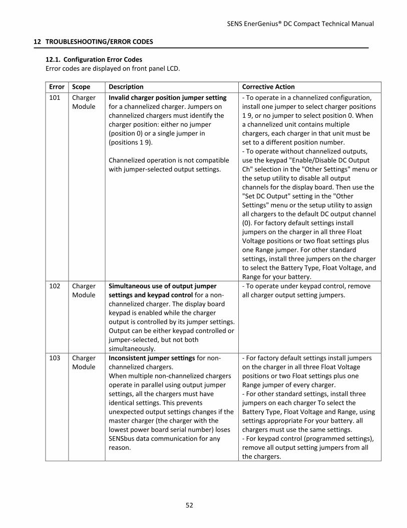
SENS EnerGenius® DC Compact Technical Manual
52
12 TROUBLESHOOTING/ERROR CODES
12.1. Configuration Error Codes Error codes are displayed on front panel LCD.
Error Scope Description Corrective Action
101 Charger Module
Invalid charger position jumper setting for a channelized charger. Jumpers on channelized chargers must identify the charger position: either no jumper (position 0) or a single jumper in (positions 1 9). Channelized operation is not compatible with jumper-selected output settings.
- To operate in a channelized configuration, install one jumper to select charger positions 1 9, or no jumper to select position 0. When a channelized unit contains multiple chargers, each charger in that unit must be set to a different position number. - To operate without channelized outputs, use the keypad "Enable/Disable DC Output Ch" selection in the "Other Settings" menu or the setup utility to disable all output channels for the display board. Then use the "Set DC Output" setting in the "Other Settings" menu or the setup utility to assign all chargers to the default DC output channel (0). For factory default settings install jumpers on the charger in all three Float Voltage positions or two float settings plus one Range jumper. For other standard settings, install three jumpers on the charger to select the Battery Type, Float Voltage, and Range for your battery.
102 Charger Module
Simultaneous use of output jumper settings and keypad control for a non-channelized charger. The display board keypad is enabled while the charger output is controlled by its jumper settings. Output can be either keypad controlled or jumper-selected, but not both simultaneously.
- To operate under keypad control, remove all charger output setting jumpers.
103 Charger Module
Inconsistent jumper settings for non-channelized chargers. When multiple non-channelized chargers operate in parallel using output jumper settings, all the chargers must have identical settings. This prevents unexpected output settings changes if the master charger (the charger with the lowest power board serial number) loses SENSbus data communication for any reason.
- For factory default settings install jumpers on the charger in all three Float Voltage positions or two Float settings plus one Range jumper of every charger. - For other standard settings, install three jumpers on each charger To select the Battery Type, Float Voltage and Range, using settings appropriate For your battery. all chargers must use the same settings. - For keypad control (programmed settings), remove all output setting jumpers from all the chargers.

SENS EnerGenius® DC Compact Technical Manual
53
104 Charger Module
Invalid output channel. Chargers must be set to use a valid output channel setting: either an assigned output channel 1 4 (representing Ch A Ch D, respectively) for channelized systems or 0 for non-channelized operation. Combining channelized chargers with non-channelized chargers in the same unit (or system) is not supported.
- If necessary, enable the channel using the keypad "Enable/Disable DC Output Ch" selection in the "Other Settings" menu or the setup utility. - To select a different output channel, reassign the charger to match its actual output channel connection using the "Set DC Output" setting in the "Other Settings" menu or by using the setup utility. - To operate without channelized outputs, use the keypad "Enable/Disable DC Output Ch" selection in the "Other Settings" menu or the setup utility to disable all output channels for the display board. Then use the "Set DC Output" setting in the "Other Settings" menu or the setup utility to assign all chargers to the default DC output channel (0). For factory default settings install jumpers on the charger in all three Float Voltage positions or two float settings plus one Range jumper. For other standard settings, install three jumpers on the charger to select the Battery Type, Float Voltage, and Range for your battery.
105 Charger Module
Duplicate charger location settings within a unit with channelized outputs. Every charger in a unit configured for channelized outputs must have a unique charger location setting. Duplication is allowed for chargers in different units, i.e. with different "Unit Serial Numbers". Non-channelized units do not use charger positions.
- use a different position number (jumper setting) For each charger in a channelized multi-charger unit. - When replacing a charger in a channelized multi-charger unit, set the replacement charger For the same position as the charger being removed. - To prevent confusion, the position jumper settings should agree with the position markings on labels, internal wiring, etc. (so the displayed charger ID number will match its physical and electrical position).
106 Charger Module
Invalid jumper settings for a non-channelized charger. Non-channelized chargers must use either no jumpers (for programmed settings, including keypad control) or a valid three jumper combination to select either factory settings or other standard settings.
- For software programmed settings (with or without keypad control), remove all charger output setting jumpers. - For factory default settings install jumpers on the charger in all three Float Voltage positions or two Float settings plus one Range jumper. - For other standard settings install three jumpers on the charger to select the Battery Type, Float Voltage, and Range for your battery.

SENS EnerGenius® DC Compact Technical Manual
54
201 Channel No chargers assigned to output channel. Every enabled output channel must have at least one charger assigned to it. When none is found, it is presumed that a charger has failed, has lost SENSbus data communication, or has an incorrect channel setting.
- Check for a charger that has failed (indicated by its LED status). - Check for disconnected or damaged SENSbus data cables. - If the output channel is not to be used, disable it by using the keypad "Enable/Disable DC Output Ch" setting in the "Other Settings" menu or the PC utility.
202 Channel Too few chargers operating. The combined output rating of all chargers operating on this channel is less than the channel's rated output. This can occur because a charger has failed, has an open AC input or DC output connection, has lost SENSbus data communication, is configured for the wrong output channel, etc. Note: the channel output settings are used to determine channel-level output current limit settings for "N+1" and "N+2" redundant configurations; non-redundant systems use channel settings of 0 which allow up to 100% output from every available charger.
- Use the "Set DC Output" setting in the "Other Settings" menu or the setup utility to verify all chargers' output channel settings. Each charger must be set for the output channel corresponding to its electrical DC output connection. - Use the setup utility to verify the channel DC output current and power ratings. For "N+1" or "N+2" redundant operation use the required output rating, i.e. the total for the minimum number of chargers ("N") that will provide the necessary output ratings. Non-redundant systems use 0 settings (which disables this error check). - If necessary, install additional chargers to meet the required output rating (plus the additional chargers needed for "N+1" or "N+2" redundant operation). - Verify that each channel is assigned enough chargers to meet the required DC output rating (plus any extra chargers needed to provide "N+1" or "N+2" redundant operation). - Check for disconnected or damaged SENSbus data cables. - Check for miswired, disconnected, or damaged input and output connections.
203 Channel Charger assigned to a disabled channel. All chargers must either be set for non-channelized operation (0, Default output) or to a valid output channel that is enabled in this unit or system.
- To use this channel, enable it using the keypad "Enable/Disable DC Output Ch" selection in the "Other Settings" menu or the setup utility. Verify that the DC outputs of all chargers assigned to this channel are electrically connected to that output bus. - To select a different output channel, reassign the charger to match its actual output channel connection using the "Set DC Output" setting in the "Other Settings" menu or by using the setup utility. - To operate without channelized outputs, use the keypad "Enable/Disable DC Output Ch" selection in the "Other Settings" menu or the setup utility to disable all output channels for the display board. Then use the

SENS EnerGenius® DC Compact Technical Manual
55
"Set DC Output" setting in the "Other Settings" menu or the setup utility to assign all chargers to the default DC output channel (0). For factory default settings install jumpers on the charger in all three Float Voltage positions or two float settings plus one Range jumper. For other standard settings, install three jumpers on the charger to select the Battery Type, Float Voltage, and Range for your battery.
301 Unit (or System)
Missing chargers. A charger that should be present is missing, has failed, or otherwise not found on the SENSbus network. The number of chargers in this system must not be less than the System Charger Count setting. This setting defines how many chargers should be installed, particularly in "N+1" and "N+2" redundant configurations (where full output is possible without all chargers operating). This setting normally is 0 (Off) for non-redundant systems, which disables this error check.
- Check for a charger that has failed (indicated by its LED status). - Check for disconnected or damaged SENSbus data cables. - Use the "Minimum System Number of Chargers" selection in the "Other Settings" menu or the PC utility to verify the System Charger Count setting. For "N+1" or "N+2" redundant operation this should be the number of charger modules connected to the SENSbus network. Non-redundant systems normally use a 0 setting (which disables this error check) but may be set if error checking is desired.
302 Unit (or System)
Channel Charger assignments used but not all chargers are set for the DC channel. If Channel-Charger Assignments are used, ALL installed Charger Ids must be set.
-To correct this, the SENS Setup Utility must be used to assign Charger Ids to a channel.
303 Unit (or System)
Channel Charger assignments used but not all chargers are set for the AC channel. If Channel-Charger Assignments are used, ALL installed Charger Ids must be set.
-To correct this, the SENS Setup Utility must be used to assign Charger Ids to a channel.
304 Unit (or System)
Duplicate Charger Id found in system using Assigned Chargers. If assigned chargers feature is used, Charger Ids MUST be unique. The system will continue to operate, but this indicates that jumpers need to be adjusted.
Corrective action is to use the SENS Setup Utility to change the Unit Serial number to match the unit the module was installed in.
305 Unit (or System)
Rogue Module Found. This can apply to any type of system. It indicates that a charger module was found that has a Unit Serial Number that does not match any display found on the bus. This could happen when adding a module from another system.
Corrective action is to fix Unit Serial Numbers on all chargers/modules and Accessory boards.

SENS EnerGenius® DC Compact Technical Manual
56
401 Hardware Optional Hardware Error. Hardware that may be optional is not working properly.
This could be a bad configuration. Compare Option Select Bits with Hardware Status Bits to determine if perhaps a piece of hardware is configured to be present but doesn't actually exist on this board.
402 Hardware Critical Hardware Error. Critical Hardware is not working properly.
Check Hardware Status Bits to determine the specific hardware that is not behaving. This may require a board replacement.
12.2. Troubleshooting
AC LED DC LED Fan / Filter LED
Symptom Possible Causes Recommended Actions
OFF OFF - Display AC and DC LEDs and display are off
1. Proper AC or DC voltages not applied 2. Cable to display board failure or poor connection 3. Display board failure
1. Using a voltmeter, check that AC input voltage and frequency at AC input terminal block/breaker are in the range 188VAC – 528VAC / 47Hz – 63Hz or that >60VDC is present at DC output terminal block/breaker and that the DC polarity is correct. Correct charger AC input and DC output voltage as required. 2. If step 1 doesn’t resolve issue, remove both AC and DC power for 1 minute, then reapply power. 3. If steps 1 and 2 don’t resolve issue, remove front cover while leaving cables connected and verify the network cable at the SENSbus port at the top of the display board is tightly connected. 4. If none of the above steps resolved the issue, display board may need to be replaced. Contact SENS.
SOLID GREEN
FLASH or SOLID GREEN
- Unable to Communicate using MODBUS
1. No communication bus termination installed 2. Communication cable is plugged into the wrong charger port 3. Wiring is incorrect 4. Incorrect MODBUS settings (baud rate, address)
1. Verify that a terminator is installed as directed in the manual (note that a terminator is not required if the charger is not at the end of the communication bus). 2. If terminator is installed, verify that communication cable is connected to ports as directed in the manual, in the Modbus connections section. Correct cabling as required. 3. For serial applications, if cable is connected correctly, verify that

SENS EnerGenius® DC Compact Technical Manual
57
Modbus +D1 (A) goes to pin 5 of J2 and that Modbus –D0 (B) goes to pin 4 of J2. 4. If cable wiring is correct, verify that charger and application MODBUS settings are as required. Adjust settings using setup utility as required.
SOLID GREEN
SOLID RED - AC good, charger fail or overvoltage shutdown
1. Charger has experienced an unexpected fault 2. Programmed setting are incorrect (OVSD set too low) 3. Charger module failure
1. Remove both AC and DC power for 1 minute, then reapply power. 2. If fault remains, check overvoltage shutdown settings and again remove both AC and DC power for 1 minute, then reapply power. 3. If steps 1 and 2 don’t resolve issue, a charger failure is the likely cause.
SOLID GREEN
FLASHING RED/ YELLOW
- Charger’s output is not enabled
1. A battery is connected to the charger output with reverse polarity
1. Correct DC polarity applied to DC output terminal block/breaker.
SOLID GREEN
SOLID YELLOW
- AC good, high battery voltage
1. Alarm setpoint incorrect for application 2. DC voltage is high due to an external source
1. Check that charger battery settings and alarms are set appropriately for the application and battery under charge. 2. If settings and alarms are correct, check and correct battery / load voltage (consider battery surface charge and any other connected equipment).
SOLID GREEN
SOLID YELLOW
- AC good, low battery voltage
1. Alarm setpoint incorrect for application 2. Battery discharged or defective
1. Check that charger battery settings and alarms are set appropriately for the application and battery under charge. 2. If settings and alarms are correct, check and correct battery / load voltage (consider loads and any connected equipment).
SOLID GREEN
FLASHING YELLOW
AC good, low incompatible battery error (charger disabled)
1. Voltage range improperly set
1. Check that charger voltage range is set correctly for the battery. After making any correction to the range setting, remove both AC and DC power for 1 minute, then reapply power.

SENS EnerGenius® DC Compact Technical Manual
58
SOLID GREEN
FLASHING GREEN/ YELLOW
- AC good, output power limited
1. Charger power is reduced to protect charger due to high temperatures
1. Check for obstructions on ventilation openings 2. Ensure that all covers are installed as directed in manual. 3. Reduce operating environment temperature. Charger will automatically increase power as temperature is lowered.
SOLID GREEN
DOUBLE FLASH YELLOW
- AC good, load share fail
1. Charger output settings do not match between chargers
1. Check that individual charger settings are identical. Adjust as required. After making any adjustments, unplug and re-plug load share cable from charger.
SOLID GREEN
DOUBLE FLASH RED
- AC good, output disabled
1. Too many devices on the SENSbus network
1. Ensure that less than max allowed number of devices is on the SENSbus. 2. If step 1 doesn’t resolve issue, a failed display board is likely, contact SENS
SOLID RED
SOLID GREEN
- AC fail, battery voltage good
1. Proper AC voltages or frequency not applied 2. Charger failure
1. Using a voltmeter, check that AC input voltage and frequency at AC input terminal block/breaker are in the range 188VAC – 428VAC / 47Hz – 63Hz. Correct charger AC input voltage as required 2. If step 1 doesn’t resolve issue, a charger failure is the likely cause. Replace charger.
SOLID RED
SOLID YELLOW
- AC fail, high battery voltage
1. Proper AC voltages or frequency not applied 2. Charger failure And 3. Alarm setpoint incorrect for application 4. DC voltage is high due to an external source such as an alternator
AC LED 1. Using a voltmeter, check that AC input voltage and frequency at AC input terminal block/breaker are in the range 188VAC – 428VAC / 47Hz – 63Hz or that > 60VDC is present at DC output terminal block/breaker and that the DC polarity is correct. Correct charger AC input and DC output voltage as required. 2. If step 1 doesn’t resolve RED AC light, remove both AC and DC power for 1 minute, then reapply power. 3. If steps 1 and 2 don’t resolve RED AC light, a charger failure is the likely cause. Replace charger. DC LED 1. Check that charger battery settings and alarms are set

SENS EnerGenius® DC Compact Technical Manual
59
appropriately for the application and battery under charge. 2. If settings and alarms are correct, check and correct battery / load voltage (consider battery surface charge, alternator, and any connected equipment).
SOLID RED
SOLID YELLOW
- AC fail, low battery voltage
1. Proper AC voltages or frequency not applied 2. Charger failure And 3. Alarm setpoint incorrect for application 4. Battery discharged or defective
AC LED 1. Using a voltmeter, check that AC input voltage and frequency at AC input terminal block/breaker are in the range 188VAC – 428VAC / 47Hz – 63Hz or that > 60VDC is present at DC output terminal block/breaker and that the DC polarity is correct. Correct charger AC input and DC output voltage as required. 2. If step 1 doesn’t resolve RED AC light, remove both AC and DC power for 1 minute, then reapply power. 3. If steps 1 and 2 don’t resolve RED AC light, a charger failure is the likely cause. Replace charger. DC LED 1. Check that charger battery settings and alarms are set appropriately for the application and battery under charge. 2. If settings and alarms are correct, check and correct battery / load voltage (consider loads and any connected equipment). 3. If fault remains after the above steps, check battery health. Replace battery if weak.

SENS EnerGenius® DC Compact Technical Manual
60
SOLID RED
SOLID RED - AC fail, charger fail or overvoltage shutdown
1. Charger is in a fault state 2. Charger failure
AC LED 1. Using a voltmeter, check that AC input voltage and frequency at AC input terminal block/breaker are in the range 188VAC – 428VAC / 47Hz – 63Hz or that > 60VDC is present at DC output terminal block/breaker and that the DC polarity is correct. Correct charger AC input and DC output voltage as required. 2. If step 1 doesn’t resolve RED AC light, remove both AC and DC power for 1 minute, then reapply power. 3. If steps 1 and 2 don’t resolve RED AC light, a charger failure is the likely cause. Replace charger. DC LED 1. Remove AC and DC power from charger for 1 minute before reapplying power. Ensure AC voltage and/or DC voltage is within specified operating limits of the charge. 2. If fault remains, check overvoltage shutdown settings and again remove both AC and DC power for 1 minute, then reapply power. 3. If steps 1 and 2 don’t resolve issue, a charger failure is the likely cause. Replace charger.
SOLID RED
FLASHING YELLOW
- AC fail, low incompatible battery error
1. Proper AC voltages or frequency not applied 2. Charger failure And 3. Voltage improperly set
AC LED 1. Using a voltmeter, check that AC input voltage and frequency at AC input terminal block (J100) are in the range 188VAC – 428VAC / 47Hz – 63Hz or that >60VDC is present at DC output terminal block/breaker and that the DC polarity is correct. Correct charger AC input and DC output voltage as required. 2. If step 1 doesn’t resolve RED AC light, remove both AC and DC power for 1 minute and then reapply power. 3. If steps 1 and 2 don’t resolve RED AC light, a charger failure is the likely cause. Replace charger.

SENS EnerGenius® DC Compact Technical Manual
61
DC LED 1.Check that charger voltage is set correctly for the battery. After making any correction to the setting, remove both AC and DC power for 1 minute, then reapply power.
ALTERNATING FLASHING YELLOW
- No output 1. Illegal configuration
1. Ensure that charger has been programmed to desired and allowable settings.
SYNCHRONIZED FLASHING YELLOW
- No output 1. Missing terminator 2. Missing/damaged rectifier device
1. Verify a terminator is connected in the display board SENSbus port. 2. If step 1 doesn’t resolve issue, a charger failure is the likely cause. Contact SENS or replace charger.
ALTERNATING FLASHING RED
- No output 1. Missing or invalid code (boot load required)
1. Update charger firmware using setup utility. 2. If step 1 doesn’t resolve issue or setup utility is not available, replace charger
ALTERNATING FLASHING GREEN
- Starting-up 1. Charger is still powering-on 2. Failed display board
1. Remove both AC and DC power for 1 minute and then reapply power. Allow charger at least 1 minute to fully boot. 2. If step 1 doesn’t resolve issue, a display board failure is the likely cause. Replace display board.
- - YELLOW Filter Error Filter Issue 1. Clean module filter as directed in manual. 2. Ensure ventilation openings are not obstructed.
- - RED Fan Error Fan Failure 1. Replace module fans as directed in manual.

SENS EnerGenius® DC Compact Technical Manual
62
13 GLOSSARY
Original Factory Configuration Configuration set at the factory. Charger operates using settings configured at the factory per customer order. See configuration details on inside cover label.
Float Voltage Float output voltage is used to maintain batteries in a fully charged state and prevents a fully charged battery from becoming overcharged.
Boost Voltage “Boost” describes an elevated output voltage employed to accelerate the recharge of a battery that is periodically discharged. The voltage employed to boost charge batteries is typically the same as that employed to “equalize” cells of a battery on long-term float charge. The terms “Boost” and “Equalize” are often used interchangeably. SENS’ convention is to employ the term “Boost” when referring to both the fast recharge function and the cell equalization function described under the definition of “Equalize Voltage”.
Equalize Voltage “Equalize” describes an elevated voltage typically employed to reset the series-connected cells of a battery such that cell voltages and capacities more nearly match each other. Equalize charging is employed to improve the performance and life of an already charged battery that is primarily charged using Float voltage. SENS’ convention is to employ the term “Boost” to mean both this cell equalization function and the fast battery recharge function.
Battery Type Indicates the type of battery being charged. Battery type is selected when ordering charger and may be adjusted using the front panel keypad. Supported battery types include flooded lead-acid, absorbed glass mat (AGM), valve-regulated lead-acid, and nickel-cadmium.
Configuration Code Indicates charger output voltage configuration. Configuration code is included on the inside cover label.
Modbus Modbus is an application layer messaging protocol provided by Modbus Organization and used for client/server communication. Modbus is provided over RS-485 in RTU mode or over TCP/IP as an option.

20.30
11.00
18.303X .885FOR 1/2 IN CONDUIT
1.362FOR 1 IN CONDUIT
4X 6.31
0
1.38
3.25
4.63
6.00
8.30
19.50
8.00
8.00
4X .28
A
4X MOUNTING LOCATIONSFOR 1/4IN HARDWARE
***ENSURE NO DEBRIS OR PARTICLES FALL INTO UNIT DURING INSTALLATION***
.281
.500
.375
DETAIL ASCALE 1 : 1
2 LOCATIONS
NOTES:THIS DRAWING IS FOR REFERENCE ONLY.1.THE INSTALLATION OF THIS EQUIPMENT SHALL COMPLY WITH ALL LOCAL AUTHORITY AND APPLICABLE BUILDING CODES.2.CLEARANCES - FOR VENTILATION AND SERVICABILITY PROVIDE A MINIMUM CLEARANCE OF:3.
8 INCHES ON TOP OF THE UNIT.•6 INCHES ON BOTTOM OF THE UNIT.•2 INCHES ON EACH SIDE OF THE UNIT.•
WEIGHT: 38 LBS MAXIMUM4.***IMPORTANT*** - WHEN INSTALLTING UNIT, ENSURE THAT NO DEBRIS OR PARTICLES FALL INTO UNIT. 5.
REVISIONSDCN REV DESCRIPTION DATE APPROVED
107772 A INITIAL RELEASE 12/9/2019 ERS107839 B GENERAL UPDATE 4/16/2020 ERS
D
C
B
AA
B
C
D
12345678
8 7 6 5 4 3 2 1
E
F
E
F
DIMENSIONS & TOLERANCES PER ASME Y14.5 - 2009
BD DIA\00647SHEET 1 OF 2
DIAGRAM,ENERGNIUS DC,COMPACT,INSTALL12/9/2019
ERS
REVDOCUMENT NUMBERSIZE
DESCRIPTIONNAME DATE
CHECKED
DRAWN
THIRD ANGLE PROJECTION
UNLESS OTHERWISE SPECIFIED:
DIMENSIONS ARE IN INCHES
DEFAULT TOLERANCES:
ANGLES 1 TWO PLACE DECIMAL .02THREE PLACE DECIMAL .005
DO NOT SCALE DRAWINGTHE INFORMATION CONTAINED IN THIS DRAWING IS THE SOLE PROPERTY OF STORED ENERGY SYSTEMS, LLC. ANY REPRODUCTION IN PART OR AS A WHOLE WITHOUT THE WRITTEN PERMISSION OF STORED ENERGY SYSTEMS, LLC. IS PROHIBITED.
PROPRIETARY AND CONFIDENTIAL
1840 INDUSTRIAL CIRCLELONGMONT, CO 80501
303-678-7500WWW.SENS-USA.COM

B
B
DETAIL BSCALE 1 : 1.5
AC FIELD WIRING TERMINALSWIRING BINDING SCREW / RING LUG TYPE
WIRE RANGE 16-6AWGTORQUE TO 20 IN-LBS
GROUND TERMINALBOX LUG TYPE
WIRE RANGE: 14-4 AWGTORQUE TO 50 IN-LBS
2X OPTIONAL FORM-C CONTACTSPILOT RELAYS TO POWEREXTERNAL LOADS OR ALARMSRATED 120VAC / 5APLUGGABLE BLOCK WITH SCREW TERMINALSWIRE RANGE: 26-12AWGTORQUE TO 5.5 IN-LBS
DC FIELD WIRING TERMINALSBOX LUG TYPEWIRE RANGE: 14 - 2/0 AWGTORQUE:
14-10AWG - 35 IN-LBS•8AWG - 40 IN-LBS•6-2/0 AWG - 120 IN-LBS•
5X FORM-C ALARM RELAY CONTACTSPLUGGABLE BLOCK WITH SCREW TERMINALSWIRE RANGE: 28-16AWGTORQUE TO 2.0 IN-LBS
COMMUNICATION CONNECTIONSRJ45 TYPE
COMMUNICATION CONNECTIONSDETAIL B
SCALE 2 : 1
RS-485 MODBUS / CAN
SENSBUS
ETHERNET
ALARM RELEAYS
NOTES:WIRE RANGES REFER TO THE PHYSICAL CAPACITY OF THE TERMINALS. IN ADDITION 1.TO PHYSICAL LIMITATIONS, CONDUCTORS MUST BE ELECTRICALLY ADEQUATE PER ALL APPLICABLE ELECTRICAL SAFTEY REGULATIONS, SUCH AS THE NATIONAL ELECTRICAL CODE.
REVISIONSDCN REV DESCRIPTION DATE APPROVED
- - SEE SHEET ONE - -
D
C
B
AA
B
C
D
12345678
8 7 6 5 4 3 2 1
E
F
E
F
DIMENSIONS & TOLERANCES PER ASME Y14.5 - 2009
BD DIA\00647SHEET 2 OF 2
DIAGRAM,ENERGNIUS DC,COMPACT,INSTALL12/9/2019
ERS
REVDOCUMENT NUMBERSIZE
DESCRIPTIONNAME DATE
CHECKED
DRAWN
THIRD ANGLE PROJECTION
UNLESS OTHERWISE SPECIFIED:
DIMENSIONS ARE IN INCHES
DEFAULT TOLERANCES:
ANGLES 1 TWO PLACE DECIMAL .02THREE PLACE DECIMAL .005
DO NOT SCALE DRAWINGTHE INFORMATION CONTAINED IN THIS DRAWING IS THE SOLE PROPERTY OF STORED ENERGY SYSTEMS, LLC. ANY REPRODUCTION IN PART OR AS A WHOLE WITHOUT THE WRITTEN PERMISSION OF STORED ENERGY SYSTEMS, LLC. IS PROHIBITED.
PROPRIETARY AND CONFIDENTIAL
1840 INDUSTRIAL CIRCLELONGMONT, CO 80501
303-678-7500WWW.SENS-USA.COM

KEYPAD DISPLAY
OK
CO
M
FAIL
K5
OK
CO
M
FAILOK
CO
M
FAILOK
CO
M
FAILOK
CO
M
FAIL
K4K3K2K1
ETH
ERN
ET
AC1 BR
EAKER
DC
BREAKER
DC
SPD
AC SPD
SENSBU
S
FACTO
RY U
SB
PROTOCOL 01(DS01)
OK
CO
M
FAILOK
CO
M
FAIL
K11
K10
SENSBU
S
RELAY MODULE 01(KM01)
OPTIONAL
L1 / A
L2 / B
L3 / C
DC (+)
DC (-)
GROUND
K11
- CO
MM
ON
K11
- OK
K11
- FAI
L
K10
- CO
MM
ON
K10
- OK
K10
- FAI
L
RS4
85 /
CAN
SEN
SBU
S
ETH
ERN
ET
SPD01
SPD02
SEN
SBU
S
OK
CO
M
FAILOK
CO
M
FAILOK
CO
M
FAILOK
CO
M
FAILOK
CO
M
FAIL
K01
- CO
MM
ON
K01
- OK
K01
- FAI
L
K02
- CO
MM
ON
K02
- OK
K02
- FAI
L
K03
- CO
MM
ON
K03
- OK
K03
- FAI
L
K04
- CO
MM
ON
K04
- OK
K04
- FAI
L
K05
- CO
MM
ON
K05
- OK
K05
- FAI
L
RS4
85 /
CAN
RS4
85 /
CAN
PS01
CB01
15A
CB02
63A
TB02
TB03
TB01
W04
W05
W06
W01
W02
W03
W09
W10
W07
W08
W13W14
W17
W18
W21W22
W23
W24
W25
W41
W42
W43
W44
AC LINE 1 / A
AC NEUTRAL
DC (+)
DC (-)
GROUND
RJ45
FIELD WIRING
AC LINE 2 / B
AC LINE 3 / C
STATUS
A
REVISIONSREV DESCRIPTION DCN DATE APPROVED
A INITIAL RELEASE 107772 12/19/2019 ERS
1
B
C
D
2345678
4 3 2 18 7 6 5
A
B
C
D
.XX ±
.X ±
FINISH
MATERIAL
ANGLES ±
.XXX ±
SCALE
DSIZE
TITLE
THE INFORMATION CONTAINED IN THIS DRAWING IS THE SOLE PROPERTY OF STORED ENERGY SYSTEMS, LLC. ANY REPRODUCTION IN PART OR AS A WHOLE WITHOUT THE WRITTEN PERMISSION
OF STORED ENERGY SYSTEMS, LLC IS PROHIBITED
TOLERANCES EXCEPT AS NOTED
INCHES
DO NOT SCALE THIS DRAWING
DRAWN BYALL DIMS IN INCHES UNLESS
OTHERWISE NOTED
DATE
1840 INDUSTRIAL CIRCLELONGMONT, CO 80501
303-678-7500WWW.SENS-USA.COM
REV.
SHEET OF1
DRAWING NUMBERTHIRD ANGLE PROJECTION
WIRING DIAGRAMENERGENIUS DC,CMPCT120VDC 50A
WD\00707 B
ERS 11/22/2019
N.T.S. 1
0.020.020.005
1
SEE BILL OF MATERIAL
SENSDIMENSIONS AND TOLERANCES
PER ASME Y14.5- 2009
B GENERAL UPDATE 107839 4/16/2020 ERS
NOTES:1. THIS DRAWING REFERS TO A MAXIMUM CONFIGURED 120VDC, 50A OUTPUT MODEL2. THE FOLLOWING COMPONENTS AND ASSOCIATED WIRING ARE OPTIONAL:
- RELAY MODULE 01- SPD01 AND SPD02
3. THIS DRAWING IS FOR REFERENCE ONLY

Powering Critical Infrastructure
STORED ENERGY SYSTEMS, LLC 1840 INDUSTRIAL CIRCLE, LONGMONT, COLORADO 80501 FAX 303.678.7504 303.678.7500 www.sens-usa.com email: [email protected] FORM-319 REV B DATE ISSUED: 9/1/2021
EC Declaration of Conformity In accordance with EN ISO 17050-1:2004
Manufacturer: Stored Energy Systems
Manufacture Address: 1840 Industrial Circle Longmont, CO 80501 U.S.A.
Product Type: EnerGenius DC Battery Charger and Accessories
Model Numbers: Models DK-*, DS-*, DW-* DM-*, DU-* DR-*, and RM-* where “*” = any series of digits and dashes
Conformance to Directives:
Directive 2014/30/EU of the European Parliament and of the Council of 26 February 2014 on the harmonisation of the laws of the Member States relating to electromagnetic compatibility (recast) Directive 2014/35/EU of the European Parliament and of the Council of 26 February 2014 on the harmonisation of the laws of the Member States relating to the making available on the market of electrical equipment designed for use within certain voltage limits (recast) Commission Delegated Directive (EU) 2015/863 of 31 March 2015 amending Annex II to Directive 2011/65/EU of the European Parliament and of the Council as regards the list of restricted substances.
Harmonized and/or technical specifications applied in full:
Directive 2014/30/EU (EMC) EN 61000-6-2:2019 EN 61000-6-4:2019 – Class A
Directive 2014/35/EU (LVD)
EN 60335-1:2012/A13:2017 EN 60335-2-29:2004/A2:2010
Directive (EU) 2015/863 (RoHS)
EN 63000:2018
Place and date of first issue:
Longmont, CO USA on, April 28, 2020
Under the sole responsibility of Stored Energy Systems, the undersigned hereby declares that the equipment specified above conforms to the essential requirements of the above Directives(s) and Standard(s).
________________________________________ _September 1, 2021_______ Sam Coleman Date Compliance Manager Stored Energy Systems, LLC

FORM-257 Rev B Date Issued: 5/4/2020
SENS Limited Warranty EnerGenius® IQ and EnerGenius DC Battery Chargers What is covered? This warranty covers any defect in material and workmanship on EnerGenius IQ and EnerGenius DC model battery chargers manufactured by Stored Energy Systems, a Colorado Limited Liability Company (SENS). What this warranty does not cover: This warranty does not cover damages, defects or failures of your equipment resulting from shipping damage, accidents, installation errors, unauthorized adjustment or repair, unauthorized third-party service, failure to follow instructions, misuse, fire, flood, acts of persons not in our control, and acts of God. For how long: Five (5) years from date of shipment. What we will do: If your battery charger is defective within five years of date of shipment, we will repair it or, at our option, replace it at no charge to you. If we choose to replace your charger, we may replace it with a new or refurbished one of the same or similar design. The repair or replacement will be warranted for the remainder of the original five-year warranty period. If we determine that your charger cannot be repaired or replaced, we will refund its purchase price to you. What we ask you to do: Contact SENS service department to obtain warranty service instructions. To obtain warranty service the product, or if applicable the EnerGenius DC power module, must be returned, freight prepaid, to the factory under a Return Material Authorization (RMA) number provided by SENS. If, in SENS’ opinion, the problem can be rectified in the field, SENS may elect to ship replacement parts for customer installation instead of having the product returned to the factory. Limitation: This warranty is limited to defects in material or workmanship of the product. It does not cover loss of time, inconvenience, property damage or any consequential damages. Repair, replacement or refund of the purchase price of the equipment is your exclusive remedy.