compact blue-green laserscatdir.loc.gov/catdir/samples/cam034/2003268603.pdf · 2003. 7. 14. ·...
TRANSCRIPT
COMPACT BLUE-GREEN LASERS
W. P. RISKT. R. GOSNELLA. V. NURMIKKO

published by the press syndicate of the univers ity of cambridgeThe Pitt Building, Trumpington Street, Cambridge, United Kingdom
cambridge univers ity pressThe Edinburgh Building, Cambridge CB2 2RU, UK40 West 20th Street, New York, NY 10011-4211, USA
477 Williamstown Road, Port Melbourne, VIC 3207, AustraliaRuiz de Alarcon 13, 28014 Madrid, Spain
Dock House, The Waterfront, Cape Town 8001, South Africa
http://www.cambridge.org
C© Cambridge University Press 2003
This book is in copyright. Subject to statutory exceptionand to the provisions of relevant collective licensing agreements,
no reproduction of any part may take place withoutthe written permission of Cambridge University Press.
First published 2003
Printed in the United Kingdom at the University Press, Cambridge
TypefaceTimes 11/14 pt SystemLATEX2ε [tb]
A catalogue record for this book is available from the British Library
ISBN 0 521 62318 9 hardbackISBN 0 521 52103 3 paperback
Contents
Preface pagexi
1 The need for compact blue-green lasers 11.1 A short historical overview 11.2 Applications for compact blue-green lasers 3
1.2.1 Optical data storage 31.2.2 Reprographics 51.2.3 Color displays 61.2.4 Submarine communications 81.2.5 Spectroscopic applications 121.2.6 Biotechnology 14
1.3 Blue-green and beyond 17References 17
Part 1 Blue-green lasers based on nonlinear frequency conversion 202 Fundamentals of nonlinear frequency upconversion 20
2.1 Introduction 202.2 Basic principles of SHG and SFG 21
2.2.1 The nature of the nonlinear polarization 212.2.2 Frequencies of the induced polarization 232.2.3 Thed coefficient 282.2.4 The generated wave 302.2.5 SHG with monochromatic waves 342.2.6 Multi-longitudinal mode sources 342.2.7 Pump depletion 38
2.3 Spatial confinement 432.3.1 Boyd–Kleinman analysis for SHG with circular
gaussian beams 432.3.2 Guided-wave SHG 51
v

vi Contents
2.4 Phasematching 562.4.1 Introduction 562.4.2 Birefringent phasematching 572.4.3 Quasi-phasematching (QPM) 712.4.4 Waveguide phasematching 902.4.5 Other phasematching techniques 972.4.6 Summary 101
2.5 Materials for nonlinear generation of blue-green light 1012.5.1 Introduction 1012.5.2 Lithium niobate (LN) 1012.5.3 Lithium tantalate (LT) 1082.5.4 Potassium titanyl phosphate (KTP) 1102.5.5 Rubidium titanyl arsenate (RTA) 1152.5.6 Other KTP isomorphs 1192.5.7 Potassium niobate (KN) 1192.5.8 Potassium lithium niobate (KLN) 1212.5.9 Lithium iodate 1232.5.10 Beta barium borate (BBO) and lithium
borate (LBO) 1242.5.11 Other materials 126
2.6 Summary 130References 130
3 Single-pass SHG and SFG 1493.1 Introduction 1493.2 Direct single-pass SHG of diode lasers 151
3.2.1 Early experiments with gain-guided lasers 1513.2.2 Early experiments with index-guided lasers 1543.2.3 High-power index-guided narrow-stripe lasers 1563.2.4 Multiple-stripe arrays 1573.2.5 Broad-area lasers 1603.2.6 Master oscillator–power amplifier (MOPA)
configurations 1613.2.7 Angled-grating distributed feedback (DFB)
lasers 1693.3 Single-pass SHG of diode-pumped solid-state lasers 170
3.3.1 Frequency-doubling of 1064-nm Nd:YAGlasers 177
3.3.2 Frequency-doubling of 946-nm Nd:YAG lasers 1773.3.3 Sum-frequency mixing 178
3.4 Summary 178References 179

Contents vii
4 Resonator-enhanced SHG and SFG 1834.1 Introduction 1834.2 Theory of resonator enhancement 187
4.2.1 The impact of loss 1894.2.2 Impedance matching 1914.2.3 Frequency matching 1934.2.4 Approaches to frequency locking 1944.2.5 Mode matching 207
4.3 Other considerations 2134.3.1 Temperature locking 2134.3.2 Modulation 2144.3.3 Bireflection in monolithic ring resonators 215
4.4 Summary 220References 220
5 Intracavity SHG and SFG 2235.1 Introduction 2235.2 Theory of intracavity SHG 2245.3 The “green problem” 229
5.3.1 The problem itself 2295.3.2 Solutions to the “green problem” 2315.3.3 Single-mode operation 235
5.4 Blue lasers based on intracavity SHG of 946-nmNd:YAG lasers 245
5.5 Intracavity SHG of Cr:LiSAF lasers 2495.6 Self-frequency-doubling 250
5.6.1 Nd:LN 2515.6.2 NYAB 2525.6.3 Periodically-poled materials 2535.6.4 Other materials 253
5.7 Intracavity sum-frequency mixing 2535.8 Summary 255
References 2566 Guided-wave SHG 263
6.1 Introduction 2636.2 Fabrication issues 2646.3 Integration issues 269
6.3.1 Feedback and frequency stability 2706.3.2 Polarization compatibility 2766.3.3 Coupling 2826.3.4 Control of the phasematching condition 2836.3.5 Extrinsic efficiency enhancement 284

viii Contents
6.4 Summary 286References 287
Part 2 Upconversion lasers: Physics and devices 2927 Essentials of upconversion laser physics 292
7.1 Introduction to upconversion lasers and rare-earthoptical physics 2927.1.1 Overview of rare-earth spectroscopy 2957.1.2 Qualitative features of rare-earth spectroscopy 296
7.2 Elements of atomic structure 3037.2.1 The effective central potential 3037.2.2 Electronic structure of the free rare-earth ions 306
7.3 The Judd–Ofelt expression for optical intensities 3247.3.1 Basic formulation 3257.3.2 The Judd–Ofelt expression for the oscillator
strength 3297.3.3 Selection rules for electric dipole transitions 336
7.4 Nonradiative relaxation 3387.5 Radiationless energy transfer 3417.6 Mechanisms of upconversion 345
7.6.1 Resonant multi-photon absorption 3457.6.2 Cooperative upconversion 3487.6.3 Rate equation formulation of upconversion by
radiationless energy transfer 3577.6.4 The photon avalanche 360
7.7 Essentials of laser physics 3637.7.1 Qualitative picture 3647.7.2 Rate equations for continuous-wave
amplification and laser oscillation 3657.8 Summary 382
References 3838 Upconversion lasers 385
8.1 Historical introduction 3858.2 Bulk upconversion lasers 397
8.2.1 Upconversion pumped Er3+ infrared lasers 3988.2.2 Er3+ visible upconversion lasers 4108.2.3 Tm3+ upconversion lasers 4208.2.4 Pr3+ upconversion lasers 4248.2.5 Nd3+ upconversion lasers 425
8.3 Upconversion fiber lasers 4278.3.1 Er3+ fiber lasers;4S3/2 → 4I15/2 transition
at 556 nm 433

Contents ix
8.3.2 Tm3+ fiber lasers 4368.3.3 Pr3+ fiber lasers 4458.3.4 Ho3+ fiber lasers,5S2 → 5I8 transition
at∼550 nm 4558.3.5 Nd3+ fiber lasers 457
8.4 Prospects 458References 460
Part 3 Blue-green semiconductor lasers 4689 Introduction to blue-green semiconductor lasers 468
9.1 Overview 4689.2 Overview of physical properties of wide-bandgap
semiconductors 4709.2.1 Lattice matching 4709.2.2 Epitaxial lateral overgrowth (ELOG) 4729.2.3 Basic physical parameters 474
9.3 Doping in wide-gap semiconductors 4759.4 Ohmic contacts forp-type wide-gap semiconductors 478
9.4.1 Ohmic contacts top-AlGaInN 4799.4.2 New approaches top-contacts 4819.4.3 Ohmic contacts top-ZnSe: bandstructure
engineering 4829.5 Summary 484
References 48410 Device design, performance, and physics of optical gain of the
InGaN QW violet diode lasers 48710.1 Overview of blue and green diode laser device issues 48710.2 The InGaN MQW violet diode laser: Design and
performance 48810.2.1 Layered design and epitaxial growth 48810.2.2 Diode laser fabrication and performance 496
10.3 Physics of optical gain in the InGaN MQW diode laser 50110.3.1 On the electronic microstructure of InGaN QWs 50610.3.2 Excitonic contributions in green-blue
ZnSe-based QW diode lasers 50910.4 Summary 513
References 51311 Prospects and properties for vertical-cavity blue light emitters 517
11.1 Background 51711.2 Optical resonator design and fabrication: Demonstration
of optically-pumped VCSEL operation in the380–410-nm range 518

x Contents
11.2.1 All-dielectric DBR resonator 51911.2.2 Stress engineering of AlGaN/GaN DBRs 521
11.3 Electrical injection: Demonstration resonant-cavityLEDs 524
11.4 Summary 530References 530
12 Concluding remarks 533References 536
Index 537

1
The need for compact blue-green lasers
1.1 A SHORT HISTORICAL OVERVIEW
For years after its invention in 1961, the laser was described as a remarkable toolin search of an application. However, by the late 1970s and early 1980s, a varietyof applications had emerged that were limited in their implementation by lack ofa suitable laser. The common thread running through these applications was theneed for a powerful, compact, rugged, inexpensive source of light in the blue-greenportion of the spectrum. The details varied greatly, depending on the application:some required tunability, some a fixed wavelength; some required a minisculeamount of optical power, others a great deal; some required continuous-wave (cw)oscillation, others rapid modulation.In many of these applications, gas lasers – such as argon-ion or helium-cadmium
lasers–were initially used toprovideblue-green light, and in somecaseswere incor-porated into commercial products; however, they could not satisfy the requirementsof every application. The lasing wavelengths available from these lasers are fixedby the atomic transitions of the gas species, and some applications required a laserwavelength that is simply not available from an argon-ion or helium–cadmiumlaser. Other applications required a degree of tunability that is unavailable from agas laser. In many of them, the limited lifetime, mechanical fragility, and relativelylarge size of gas lasers was a problem.At about the same time, new options for generation of blue-green radiation be-
gan to appear, due to developments in other areas of laser science and technology.The development of highly efficient, high-power semiconductor diode lasers atwavelengths around 810 nm opened up the possibility of diode-pumping solid-state lasers, such as those based on neodymium-doped crystals and glasses. Newand improved nonlinear materials made it practical to apply second-harmonicgeneration to the infrared outputs of these diode-pumped solid-state lasers togenerate wavelengths in the blue-green regions of the spectrum. Demonstrations in
1

2 1 The need for compact blue-green lasers
1986 of compact green sources based on intracavity frequency doubling of diode-pumped neodymium lasers by researchers at Spectra-Physics and Stanford Univer-sity sparked tremendous interest in sources based on this approach. This interest hasled to commercially-available diode-pumped green sources with powers of severalwatts and, more recently, blue sources with powers of several milliwatts.Rather than pump a neodymium laser, why not simply use nonlinear optics to
frequency double the output of an infrared semiconductor laser directly? The reasonhas been, until fairly recently, that high-power semiconductor diode lasers have hadrather broad spectral distributions and rather poor spatial beam quality. While thesecharacteristics did not prevent the use of these diode lasers as pumps for solid-statelasers, they did inhibit their use for direct nonlinear frequency conversion, in whichthe spectral and spatial mode properties of the infrared source are much more criti-cal. As the spatial and spectral mode properties of high-power semiconductor diodelasers have improved, however, the same techniques of nonlinear frequency conver-sion have been applied to direct frequency-doubling of these devices, and efficientblue and green sources have been demonstrated. In some cases, resonant enhance-ment and guided-wave geometries have been used to increase the efficiencies ofthese nonlinear interactions.An alternative approach to blue-green light generation using infrared sources
is the so-called “upconversion laser”. In a standard laser, energy conservation re-quires that the energy of an absorbed pump photon be greater than the energyof an emitted laser photon; hence the pump wavelength must be shorter than thelasing wavelength. In upconversion lasers, the energy from two or more pump pho-tons is combined to excite the lasing transition; thus the pump wavelength can belonger than the lasing wavelength, so that, for example, infrared light can be usedto directly pump a green laser. Although upconversion lasing was demonstratedin 1971 by Johnson and Guggenheim (1971), the field remained largely dormantfor several years because flashlamp pumping of such lasers was inefficient. Ex-periments conducted at IBM in 1986 which demonstrated efficient laser pumpingof upconversion lasers revived interest in the field. These initial experiments usedbulk rare-earth-doped crystals and had to be performed at cryogenic temperatures,but they demonstrated the feasibility of these devices, including the fact that theycould be efficiently pumped with laser diodes. Later, efficient room-temperatureoperation was achieved using optical fibers doped with rare-earth elements.Perhaps the most direct and attractive way to generate blue and green light
is to use a semiconductor diode laser. Semiconductor laser devices are efficient,small, robust, rugged, and powerful. However, in order to generate blue-greenradiation, semiconductorswith bandgapsof∼3eVmust beused.Suitablematerialssystems include II–VI semiconductors such as ZnS and ZnSe, and wide-gap III–Vmaterials such as GaN. The growth of thin films of these semiconductors suitable

1.2 Applications 3
for device fabrication has proven to be an extremely difficult challenge. However,breakthroughs in the growth of appropriately-doped films in both material systemshas allowed the demonstration of light-emitting diodes (LEDs) and, more recently,lasers in both material systems. However, despite rapid progress, demonstration ofcontinuous-wave (cw) operation at room temperature with powers and lifetimescomparable to infrared semiconductor lasers has not yet been achieved, and moredevelopment is required before these lasers can be used in the applications citedabove.
1.2 APPLICATIONS FOR COMPACT BLUE-GREEN LASERS
One of the factors that has made the field of compact blue-green lasers interestingand vibrant is its diversity in both the variety of technical approaches used to pro-duce them and the wide range of applications for which they have been sought. Thespecialized topical meetings that sprang up in the early 1990s in response to theintense interest and activity in this field (such as the Optical Society of America’sTopical Meeting on Compact Blue-Green Lasers, held in 1992, 1993, and 1994)brought together researchers from such disparate fields as submarine communi-cations and DNA sequencing. In this section, we review some of the principalapplications for which blue-green lasers have been sought, and the requirementsplaced on the lasers by these uses.
1.2.1 Optical data storage
The terms “optical data storage” and “optical recording” have been used to referto a variety of different approaches for recording and retrieving information usingoptical methods, including those based on such exotic phenomena as persistentspectral hole burning (Lenthet al., 1986). However, these terms usually refer tosomewhat more mundane systems that read data from (and, in some cases, writedata to) spinning disks in a fashion analogous to magnetic disk drives (Figure 1.1).In optical data storage systems, a bit is stored on the disk by altering some
physical characteristic of the disk in a tiny spot. This alteration can be done once,as in the case of read-only disks (such as audio CDs and CD-ROMs), or it can bedone repeatedly, as in the case of rewritable disks (such as those based onmagneto-optic or phase-change media). To read back the information stored on an opticaldisk, a focused laser beam is scanned over these spots and the light reflected fromthe disk is detected. The physical characteristic that was altered to record a bit mustproduce a corresponding change in some optical property of the reflected beam. Inaudio CDs andCD-ROMs, data are impressed upon a plastic disk in the form of tinypits stamped into the disk by themanufacturer. The depth of these pits is one-fourth

4 1 The need for compact blue-green lasers
Focusing Lens
Laser Beam
Rotating Disk
Figure 1.1: Optical data storage system.
the laser wavelength, so that when the beam is scanned over the pit, the portionreflected from the bottom of the pit travels an additional half-wavelength comparedwith the light reflected from thesurfaceof thediskand is therefore180◦ out-of-phasewith it; thus, the amplitude of the reflected beam is diminished due to destructiveinterference. In “magneto-optic” media, data are recorded by using the laser beamas a heater: the focused laser spot heats the magnetic material above the Curietemperature, and the presence of an appliedmagnetic field causes themagnetizationof the medium to reverse in the heated region. When the heating is removed and thematerial cools below the Curie temperature, that reversed magnetization is “frozenin”. The data can be read back by exploiting the fact that the polarization of lightreflected from the disk in thesematerials depends on the orientation of themagneticdomain (the “polar Kerr effect”). In “phase-change” material, data are recordedby using the focused laser beam to melt the material locally and induce a phasetransition from what was originally a crystalline structure to an amorphous one.Data are read back by exploiting the fact that the amorphous state of the materialhas a different reflectivity than the crystalline state.In order to write a small mark and be able to read it back accurately, the laser
beam must be focused to as small a spot as possible. A gaussian beam can befocused by a lens to a diffraction-limited spot with a diameterd of
d� λ
NA
whereλ is the wavelength andNA is the numerical aperture of the lens. Therefore,one way to achieve a smaller spot size is to reduce the wavelength. Halving thewavelength from that of a GaAlAs laser diode at 860 nm to that of a blue laser at430 nm would cut the spot size in half, and could quadruple the storage density. Inaddition, for a given rotation rate of the disk, the data rate could be increased by a

1.2 Applications 5
factor of 2, since themarks can be placed twice as close together. An additional mo-tivation to pursue development of blue-green lasers for magneto-optic storage wasthe discovery of garnet-based recording materials that exhibit better performancein the blue-green regions of the spectrum than do their counterparts designed foruse in the infrared (Eppler and Kryder, 1995).Using a blue-green laser in an optical storage system places severe demands
upon its performance (Kozlovsky, 1995). In themagneto-optic approach, the powerrequired is comparable with that demanded of the infrared diode lasers used foroptical storage (∼40 mW) (Asthana, 1994). This may seem counterintuitive – onemight expect that since the beam is focused to a smaller spot, less power wouldbe required to produce the same temperature increase for writing. This statementis true as far as it goes; however, when reading data back with a blue beam, thereare fewer photons per milliwatt than would be present in an infrared beam, whichleads to increased noise. In order to obtain an adequate signal-to-noise ratio, therecording medium must be de-sensitized so that a higher readback power can beusedwithout erasing the data. Thus, something like 2–6mW is required for readingand 40–50mWare required for writing. For focusing to a small spot, the wavefrontaberration of the blue beam must be less than 0.05 wavelengths. The noise of theblue beam must be low:<−110 dBc (decibels below carrier) for magneto-opticstorage, where differential detection is used, and<−135 dBc for phase changeand CD-ROM, where single-ended detection is used. The laser must have a longlifetime, ideally as long as the lifetime of the drive itself (perhaps 100 000 hoursmean-time-between-failures). Finally, the laser must be inexpensive.
1.2.2 Reprographics
Reprographic applications use lasers in a fashion similiar to optical data storage –the laser is focused to a small spot and used to make a mark on some medium.Here, however, themedium is the photoconductor of a laser printer, or photographicfilm or paper. Except in certain specialized applications (for example, writing onmicrofilm), reprographics does not require as small a spot size as optical datastorage. A laser printer with 2400 dpi resolution requires that the laser beam befocused to only a 10�m spot, a size that can be achieved easily using a red ornear-infrared diode laser. However, this 10�m spot size must be maintained asthe beam is scanned rapidly over a page several centimeters wide. Decreasing thewavelength for a particular spot size relaxes the design requirements of the opticalsystem by reducing the numerical aperture required to form a spot of the desiredsize and by increasing the depth-of-field.In color reprographics, lasers can be used to expose photographic paper or film
(Owens, 1992). The considerations just described for laser printers also apply here.

6 1 The need for compact blue-green lasers
In addition, thewavelengthsof the lasersmust be chosen toprovide correct exposurefor existing photographic media. For photographic films, wavelengths of 430 nm,550 nm, and 650 nm (blue, green, red) are desired. For photographic papers, wave-lengths of 470 nm, 550 nm, and 700 nm are preferred. Powers of a few milliwattsare needed, along with good beam quality, low noise, and high stability. The abilityto directly modulate the laser at frequencies up to 50 MHz is desirable.
1.2.3 Color displays
Blue-green lasers have also been sought for use in color displays. At present, themost popular type of color display device is the cathode ray tube (CRT) used incomputer monitors and color televisions. In CRTs, colors are synthesized throughthe superposition of three primary colors – red, green, and blue – generated by anelectron beam striking one of three corresponding phosphors. The combination ofthese red, green, and blue emissions in various proportions creates the other colorsvisible on thescreen.Asimilar approachhasbeenproposed for laser-baseddisplays,in which three separate lasers would provide red, green, and blue primary colorsthat could be combined to project full-color images on a large screen (Figure 1.2).Each laser could be raster-scanned across the screen, or could remain stationaryand be used to illuminate an “image gate”, such as motion picture film or a spatiallight modulator containing the image to be projected.Lasers are attractive light sources for display applications because of their high
brightness and complete color saturation. The brightness of a laser (power emittedper unit area per unit solid angle) can be very high due to the directionality of
Screen
Deflector
Beam Combiners
Red L
aser
Green La
ser
Blue Laser
Intensity Modulators
Figure 1.2: Laser-based color projection display.

1.2 Applications 7
the beam. This high brightness leads to high efficiency for a laser-based projector,since most of the generated optical power can be directed by appropriate opticsto illuminate the screen or image gate. In contrast, a conventional motion pictureprojector uses an incandescent bulb that emits light into a 4π -steradian solid angle,most of which never reaches the screen. The ability of a laser to concentrate theemitted light into a confined solid angle provides an efficiency advantage overcompeting technologies (Glenn and Dixon, 1993).Another advantage of laser-based displays is improved color saturation. In con-
ventional CRT displays, the light emitted by the phosphor is not spectrally pure;the spectral bandwidth of the emission may be several nanometers. In the languageof color theory, the red, green, and blue colors emitted by these phosphors are not“fully saturated”: that is, the primary colors are not the “bluest blue”, “greenestgreen”, or “reddest red” that the eye can perceive, but appear somewhat washedout by the addition of white. As a result, a CRT cannot reproduce the entire rangeof colors perceptible to human vision, and in particular, cannot produce fully satu-rated colors. The range of colors that can be produced by addition of primaries canbe depicted by the “CIE chromaticity diagram” (Figure 1.3). In this diagram, fullysaturated colors (monochromatic light waves of a specifiedwavelength) correspondto points around the periphery. White corresponds to a point in the interior of the
Figure 1.3: CIE diagram showing the color space spanned byCRTphosphors (dark shading)and the color space which could be spanned in a color display using monochromatic red,green, and blue lasers to generate the primary colors (lighter shading). The primary colorsfor each system fall at the corners of the triangles, as indicated.

8 1 The need for compact blue-green lasers
diagram. If one draws a line from the “white point” out to a particular color on theperiphery, the points along that line represent various saturation levels of the samecolor; for example, fully saturated green corresponds to a point on the periphery,and points along the line correspond to increasingly paler shades of green as onemoves toward thewhite point. If one plots the points corresponding to three primarycolors on such a diagram, the range of colors that can be synthesized by combin-ing these primaries corresponds to the interior of the triangle connecting the threeprimary points. Figure 1.3 shows the points corresponding to the primary colors ofa standard color CRT monitor. Although the red CRT phosphor is nearly saturated,the blue and green phosphors are considerably less so. Thus, while a CRT monitorcan produce well-saturated reds, it is difficult to achieve well-saturated blues andgreens. A laser-based color display produces primary colors that are fully saturated(that is, spectrally-puremonochromatic waves); thus, the range of colors that can beproduced is greater and the colors themselves are richer than in a CRT. In order forthe primary colors to appear to human vision as true blues, greens, and reds, theymust fall within the wavelength ranges depicted in Figure 1.3: 605 nm±5 nm forred, 530 nm±10 nm for green, and 470 nm±10 nm for blue (Glenn and Dixon,1993). The power required varies depending upon the size of the screen, but rangesfrom approximately 1 W per color for a 10-ft×16-ft screen to 20 mW per colorfor a 16-in CRT-like display (Valley and Ansely, 1997).
1.2.4 Submarine communications
Communication with a submerged vessel has been another important applicationdriving the development of blue-green lasers. Naval forces would like to be ableto send messages to their submarines without requiring them to rise from theiroperating depth and risk detection by an enemy (Figure 1.4). Ideally, such a com-munications system would be able to send a signal through seawater to a greatdepth and to transmit information at a rapid rate. Electromagnetic radiation canpenetrate seawater to a significant depth only at extremely low frequencies (ELFs)(<∼100 Hz) or in the blue-green portion of the optical spectrum, where minimumattenuation (the “Jerlov Minimum”) occurs for wavelengths between 400 nm and500 nm (Figure 1.5). Although ELF systems have been built and used to send mes-sages to submarines, systems using ELFs also have extremely low data rates, and inpractice, only extremely short messages can be sent. Transmitting with blue-greenwavelengths could make it possible to send messages to great depth with muchhigher data rate than with ELF. However simple this may sound in principle, thedevelopment of such a system has presented such great technical challenges that ithas been described as “the most complex communications system known to man”(Painter, 1989).

1.2 Applications 9
Figure 1.4: Signals are sent by conventional radio from a surface ship, ground sta-tion, or aircraft to an orbiting satellite. A blue-green laser aboard the satellite then re-lays the message to a submerged submarine. (Adapted with permission from Painter(1989).)
What are these challenges? Even at the Jerlov Minimum, the attenuation ofseawater is not negligible, and the signal reaching a submerged vessel may bequite weak, requiring the receiver aboard the submarine to be very sensitive. Thissensitivity introduces an additional complication: sunlight contains a significantblue-green component which can also penetrate the ocean and introduce noiseinto the received signal. One way to solve this problem is to exploit the differencebetween the very narrowspectralwidth of theblue-green laser and themuchbroaderspectral distributionof sunlight. Anoptical filterwith a sufficiently narrowpassbandcan transmitmostof theblue-green laserphotons to thedetectorwhile rejectingmostof the solar photons. In addition to a narrow passband, such a filtermust have awidefield-of-view. Photons transmitted from a satellite to a submarinemay pass throughcloud layers that introduce scattering, and are further scattered during passagethrough the sea, so that they may impinge upon the submarine from a variety of

10 1 The need for compact blue-green lasers
8006004002000.01
0.10
1.0
10
λ, Wavelength (nm)
K, D
iffuse Attenu
ation Coe
fficien
t (m
−1)
Figure 1.5: Attenuation of seawater over the blue-green portion of the optical spectrum,showing the “Jerlov Minimum” near 450 nm. Various points correspond to measurementsby different authors. [Reprinted by permission from Smith and Baker (1981).]
angles. Simultanously meeting both these requirements – narrow passband andwide field-of-view – is difficult.Themost successful approach devised to meet this challenge is the “atomic reso-
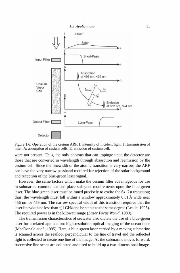
nance filter” or “ARF” (also called “QLORD”–“quantum-limited optical resonancedetector”), which has the narrow passband and wide field-of-view required for sub-marine communications (Gelbwachs, 1988). The ratio of the spectral width�λ tocenter wavelengthλ0 of the passband in these filters can be�λ/λ0 � 10−6. Thus,for a center wavelengthλ0 ∼ 500 nm, the width of the passband can be as narrowas∼0.005A (Marling et al., 1979)! An ARF based on cesium vapor is particularlysuited to submarine communications and has been pursued for this purpose. Theoperation of the cesium ARF can be understood from Figure 1.6. A conventionalfilter (e.g., colored glass such as BG-18) allows only blue-green light to enter thecesium cell. In the cesium vapor, light at 456 nm or 459 nm is absorbed to excitepopulation from the 6s level to the 7p level. This population subsequently decaysnonradiatively to the 6p level, through either the 7sor 5d levels.When the 6ppopu-lation relaxes back to the ground state, infrared photons at 852 nm or 894 nm areemitted. Another conventional filter (such as RG-715 glass) permits only infraredradiation to impinge upon the detector. Since there is no overlap in the passbandsof the two conventional filters, no light would reach the detector if the cesium cell
1.2 Applications 11
Figure 1.6: Operation of the cesium ARF. I: intensity of incident light, T: transmission offilter, A: absorption of cesium cells, E: emission of cesium cell.
were not present. Thus, the only photons that can impinge upon the detector arethose that are converted in wavelength through absorption and reemission by thecesium cell. Since the linewidth of the atomic transition is very narrow, the ARFcan have the very narrow passband required for rejection of the solar backgroundand reception of the blue-green laser signal.However, the same factors which make the cesium filter advantageous for use
in submarine communications place stringent requirements upon the blue-greenlaser. The blue-green laser must be tuned precisely to excite the 6s–7p transition;thus, the wavelength must fall within a window approximately 0.01A wide near456 nm or 459 nm. The narrow spectral width of this transition requires that thelaser linewidth be less than<∼1GHz and be stable to the same degree (Leslie, 1995).The required power is in the kilowatt range (Laser Focus World, 1980).The transmission characteristics of seawater also dictate the use of a blue-green
laser for a related application: high-resolution optical imaging of the ocean floor(MacDonaldet al., 1995). Here, a blue-green laser carried by a moving submarineis scanned across the seafloor perpendicular to the line of travel and the reflectedlight is collected to create one line of the image. As the submarine moves forward,successive line scans are collected and used to build up a two-dimensional image.

12 1 The need for compact blue-green lasers
Table 1.1.Ions and wavelengths of interest for laser coolingof trapped ions
Ion Wavelength References
Ca 397 nm, 442.7 nm Urabeet al. (1992), Hayasakaet al. (1994),Beveriniet al. (1996)
H 243 nm Zimmermannet al. (1995)Mg 383 nm Beveriniet al. (1996)Pb 368.3 nm Tamm (1993)Rb 421 nm Hemmerichet al. (1990)Sr 422 nm Barwoodet al.(1992), Barwoodet al.(1993)Yb 369.5 nm Tamm (1993)
This technique can provide detailed maps of geographical features of the seafloor,or of man-made features such as pipelines.
1.2.5 Spectroscopic applications
Laser cooling of trapped ions is of interest as the basis for optical frequency stan-dards (Itano, 1991). In this approach, an ion is held in an electromagnetic trap andcooled using radiation pressure from a laser slightly detuned from an absorptiontransition. Several ions that have been proposed for this application require a ultra-violet or blue laser for excitation of the relevant transition (Table 1.1). Convenientsources in the 300–500 nm spectral range are therefore useful for spectroscopyand laser pumping of such transitions. In most cases, relatively modest powers arerequired (at most, a few milliwatts), but the blue output must be tunable.A spectroscopic use of blue-green lasers with great immediate practical applica-
tion isin situprocess control of physical vapor deposition (PVD). A number of tech-nologically important materials are deposited in thin films from a vapor state, usingtechniques such as evaporation and sputtering. The deposition rate of these mate-rials is typically measured using a quartz crystal monitor or ion gauge. However,these techniques are not well suited to the deposition requirements ofmanymodern,technologically-important materials. For example, traditional rate-monitoringtechniques are inadequate for deposition of superconducting films, in which a highbackground pressure of oxygen is required, and for co-deposition of composite oralloy films, inwhich it is necessary to simultaneouslymonitor and control the flux ofmore than one species. In addition, these monitoring techniques require physicallyplacing a sensor within the deposition chamber. Since the sensor must not obscurethe target, or otherwise interfere with deposition of materials on it, it necessarilycannot directly measure the characteristics of the flux incident upon the substrate.An alternative technique formonitoring the evaporation flux is atomic absorption
spectroscopy. In this approach, a laser beam is passed through the atomic vapor and

1.2 Applications 13
Deposition Chamber
Source
SourceControl
FeedbackElectronics
Laser Detector
Sample
Figure 1.7: A tunable blue-green laser is used for monitoring and controlling the depositionrate in a PVD system.
is tuned to an absorption line (Figure 1.7). The beam is attenuated by absorption inthe vapor and the emerging intensity is given by Beer’s law,I = I0e−nσ l , whereI0is the initial intensity,I is the output intensity,n is the density of the evaporant,σ isthe absorption cross-section, andl is the path length. Bymeasuring the effect of theatomic vapor on the intensity of the transmitted laser beam, the evaporation rate canbe determined. In addition, this information can be fed back to the vapor source andused for closed-loop control of the evaporation rate. Unlike other techniques formonitoring evaporation rate, atomic absorption spectroscopy is noninvasive, can beused with unusual deposition geometries, is highly sensitive and species selective,and can probe both the spatial and velocity distribution of the evaporant.Atomic absorption spectroscopy can be implemented using hollow cathode
lamps; however, these lamps have a number of unattractive features, including rela-tively short lifetime (∼1000 h), low intensity, and broad spectral width (Benerofeet al., 1994). The use of a laser instead of a hollow cathode lamp offers several ad-vantages: long lifetime, high intensity, and narrow spectral width can be obtained.Because the linewidth of the laser can be very narrow, Doppler broadening of theevaporated flux canbe investigated. Sophisticated spectroscopic techniques, suchasfrequency-modulation spectroscopy (Bjorklund, 1980) or nonlinear spectroscopy(Levenson, 1982) can be employed.There are several technologically-important materials that are deposited by PVD
and that have absorption lines in the blue-green portion of the spectrum, including:aluminum (394 nm) (Wanget al., 1996), titanium (391 nm) (Galantiet al., 1996),yttrium (408 nm) (Wanget al., 1995), tungsten (385 nm), and gallium (403 nm).Again, the laser must be tunable over the relevant absorption line and powers onthe order of a milliwatt are required.

14 1 The need for compact blue-green lasers
1.2.6 Biotechnology
Blue-green lasers also have uses in the field of biotechnology (Trainor, 1990). Oneof the most important applications is flow cytometry, in which cells that havecertain properties are counted or measured as they are forced to flow by a detector.Cells with the desired property can be detected by attaching to them a fluorescentmolecule, or “fluorophore.” The flowing cells are forced to pass through the focusedbeam of a laser that is tuned to excite the fluorophore, and the presence of the cellcan be detected by looking for the associated fluorescence.One particularly important example of flow cytometry is DNA sequencing. The
objective of this procedure is to determine the sequence of the four nucleotides(adenosine, cytosine, guanosine, and thymidine) that encode genetic informationin themolecular structure of DNA. Such sequences are important for understandingand diagnosing human genetic disorders and for examining forensic evidence incriminal cases. In one technique for DNA sequencing, a portion of the code isdetermined by creating a series of replicas of a particular section of the DNAmolecule. Each replica starts at the same point in the sequence, but differs in lengthfrom the other replicas by one nucleotide (Figure 1.8). Thus, if the replicas canbe sorted by length and if the terminal nucleotide can be determined, the DNAsequence can be deduced.
Figure 1.8: A portion of the DNA sequence is determined by making a series of replicas,each of which differs by one nucleotide in length. If the replicas can be sorted by length,and the terminating nucleotide can be determined, then that portion of the DNA sequencecan be reconstructed.

1.2 Applications 15
Figure 1.9: (a) Four dyes used for tagging DNA nucleotides. (b) The corresponding absorp-tion spectra. Solid curve: fluorescein; dotted curve: NBD; dashed curve: Texas Red; dot-dash curve: tetramethylrhodamine. (c) The corresponding fluorescence spectra. Same linetypes as in (b). (Reprinted with permission from Smithet al.(1986). Copyright: MacmillanMagazines Limited.)
The terminating nucleotide of each replica can be determined by “tagging” thereplica with one of four fluorophores, each fluorophore marking the presence ofone of the four possible nucleotides. The fluorophores are chosen such that theiremission peaks are sufficiently separated to be easily resolved and identified. Fourcommon fluorescent molecules used for this purpose are shown in Figure 1.9,together with their absorption and emission spectra (Smithet al., 1986). All ofthese dyes can be excited using blue-green wavelengths.The replicas can be sorted by length by forcing them to diffuse through an
electrophoresis cell. Longer replicas move more slowly than short ones; thus, the

16 1 The need for compact blue-green lasers
Laser Excitation
Fluoresc
ence
Electrophoresis gel
RotatingFilterWheel
DNA Replicas
TaggedWith
Fluorophores
Figure 1.10: DNA replicas are sorted by diffusion throughan electrophoresis cell. Thenucleotide terminating each replica is tagged with a fluorophore. As each replica reachesthe end of the gel, excitation from a blue-green laser excites emission from the fluorophore.The fluorophore and corresponding nucleotide are identified by analyzing the fluorescentemission through a filter wheel. (Adapted with permission from Trainor (1990). Copyright:American Chemical Society.)
replicas become spatially separated as they pass through the cell, spreading out likerunners of different speeds in a race (Figure 1.10). This spatial separation corres-ponds to a temporal one; each replica crosses the “finish line” at a different time.This spatial/temporal separation is remarkably linear with respect to the length ofthe replica, and replicas that differ by only one nucleotide in length can be easilydistinguished. As each replica reaches the end of the gel, it passes through a focusedblue-green laser beam. The blue-green photons are absorbed by the fluorophore,which then fluoresces, emitting photons at its own characteristic wavelength. Thefluorophore can then be identified by analyzing the spectral content of the emit-ted photons; this can usually be done simply with a filter wheel divided intofour sections, each of which passes only the signal associated with one particularfluorophore.A great deal of development and engineering has gone into DNA sequencers
based on this technology, and several commercial products are available that useargon-ion lasers as the source of blue-green light. Hence, for compatability withexisting products, manufacturers of DNA sequencers and other flow cytometryinstrumentation seek compact blue-green lasers operating atwavelengths of 488 nmand 514 nm. The powers required can be as low as 10 mW and as high as severalwatts, depending on the details of the application (Sklar, 1992).

References 17
1.3 BLUE-GREEN AND BEYOND
In addition to the representative applications discussed above, there are numerousothers – including straightforward, but commercially important ones (such as CDmastering (Kaneda and Kubota, 1997) and semiconductor wafer inspection) andrather exotic ones (suchas calibration of neutrino detectors (Kitchin andNewcomer,1994)). These all exploit some property of blue-green light in much the same wayas those applications we have already discussed.In addition, the technologies explored for compact blue-green light generation
border onother fieldswhere identical ideasareemployed, even if generationof blue-green light is not the primary objective. For example, efficient nonlinear frequency-doubling of near-infrared light in resonators (Pereiraet al., 1988) and waveguides(Andersonet al., 1995) has been of great interest in the production and study ofsqueezed states. The same ideas used in upconversion lasers have been applied tothree-dimensional displays based on exciting visible fluorescence by absorptionof two infrared photons in a volume element defined by the intersection of twodiode laser beams in a cube of rare-earth-doped glass (Downinget al., 1996). Thedevelopment of efficient blue LEDs based on II–VI and III–V semiconductors hasbeen both a precursor to the development of lasers based on the same technologyand an important end in itself, as there are many applications for which LEDs arepreferred over lasers.Finally, the topics discussed in the remainder of this book – the basics of second-
order nonlinear processes, materials for second-harmonic generation and sum-frequencymixing, diode-pumping and intracavity frequency doubling of solid-statelasers, nonlinear frequency conversion in resonators and waveguides, rare-earthspectroscopy and the physics of upconversion lasers, and fundamentals of semi-conductor diode lasers – are relevant to the generation of wavelengths other thanblue-green ones. There is great interest in compact sources of light in portions ofthe visible spectrum other than the blue-green, and in the generation of wavelengthslonger than∼1 �m using near-infrared semiconductor and diode-pumped solid-state lasers as the starting point. Many of the basic ideas used for upconversion ofnear-infrared light to shorter wavelengths (particularly those based on nonlinearoptics) can also be used for downconversion to longer wavelengths. The funda-mentals outlined in the remainder of this book should establish a sound basis forunderstanding these devices as well.
REFERENCES
Anderson, M. E., Beck, M., Raymer, M. G., and Bierlein, J. D. (1995) Quadraturesqueezing with ultrashort pulses in nonlinear waveguides.Opt. Lett., 20, 620–622.

18 1 The need for compact blue-green lasers
Asthana, P. (1994) Laser diodes must meet tight specs for magneto-optical data storage.Laser Focus World, January, 123–125.
Barwood, G. P., Edwards, C. S., Gill, P., Klein, H. A., and Rowley, W. R. C. (1992)Development of diode and fibre laser sources for a Sr+ trapped ion optical frequencystandard.Proc. SPIE, 1837, 271–277.
Barwood, G. P., Edwards, C. S., Gill, P., Klein, H. A., and Rowley, W. R. C. (1993)Observation of the 5s 2S1/2 − 4d 2D5/2 transition in a single laser-cooled trapped Sr+ion by using an all-solid-state system of lasers.Opt. Lett., 18, 732–734.
Benerofe, S. J., Ahn, C. H., Wang, M. M., Kihlstrom, K. E., Do, K. B., Arnason, S. B.,Fejer, M. M., Geballe, T. H., Beasley, M. R., and Hammond, R. H. (1994) Dual beamatomic absorption spectroscopy for controlling thin film deposition rates.J. Vac. Sci.Technol. B., 12, 1217–1220.
Beverini, N., Maccioni, E., Strumia, F., Godone, A., and Novero, C. (1996) Frequencydoubled laser diodes: Application to Mg and Ca atomic frequency standards.LaserPhys., 6, 231–236.
Bjorklund, G. C. (1980) Frequency-modulation spectroscopy: a new method formeasuring weak absorptionsand dispersions.Opt. Lett., 5, 15–17.
Downing, E. A., Hesselink, L., Macfarlane, R. M., Klein, J. R., Evans, D., and Ralson, J.(1996) A laser-diode-driven, three-color, solid-state 3-D display. InConference onLasers and Electro-Optics, Vol. 9, 1996 OSA Technical Digest Series, pp. 89–90.Washington: Optical Society of America.
Eppler, W. R. and Kryder, M. H. (1995) Garnets for short wavelength magneto-opticrecording.J. Phys. Chem. Solids, 56, 1479–1490.
Galanti, S. A., Berzins, L. V., Brown, J. B., Tamosaitis, R. S., Bortz, M. L., Day, T., Fejer,M. M., and Wang, W. (1996) Demonstration of a vapor density monitoring systemusing UV radiation generated from quasi-phasematched SHG waveguide devices.Proc. SPIE, 2700, 334–347.
Gelbwachs, J. A. (1988) Atomic resonance filters.IEEE J. Quant. Electron., 24,1266–1277.
Glenn, W. E., and Dixon, G. J. (1993) Bright future projected for lasers in electroniccinemas.Laser Focus World, November, 73–80.
Hayasaka, K., Watanabe, M., Imajo, H., Ohmukai, R., and Urabe, S. (1994) Tunable397-nm light source for spectroscopy obtained by frequency doubling of a diodelaser.Appl. Opt., 33, 2290–2293.
Hemmerich, A., McIntyre, D. H., Zimmermann, C., and H¨ansch, T. W. (1990)Second-harmonic generation and optical stabilization of a diode laser in an externalring resonator.Opt. Lett., 15, 372–374.
Itano, W. M. (1991) Atomic ion frequency standards.Proc. IEEE., 79, 936–942.Johnson, L. F., and Guggenheim, H. J. (1971) Infrared-pumped visible laser.Appl. Phys.
Lett., 19, 44–47.Kaneda, Y., and Kubota, S. (1997) CW Solid-state ultraviolet laser for optical disk
mastering application.IEEE J. Sel. Top. Quantum Electron., 3, 35–39.Kitchin, P. J. and Newcomer, F. M. (1994) Feasibility of a frequency-doubled, pulsed
GaAs laser diode source for calibration of photomultipliers at the Sudbury NeutrinoObservatory. InProceedings of the 1993 IEEE Nuclear Science Symposium andMedical Imaging Conference, Pt. 1, pp. 686–690. IEEE.
Kozlovsky, W. (1995) Optical data storage requirements on short wavelength lasersources.Proc. SPIE, 2379, 186–190.
Laser Focus World(1980) Blue-green laser links to subs., April, 14–18.

References 19
Lenth, W., Macfarlane, R. M., Moerner, W. E., Schellenberg, F. M., Shelby, R. M., andBjorklund, G. C. (1986) High-density frequency-domain optical recording.Proc.SPIE, 695, 216–223.
Leslie, K. R. (1995). Alexandrite solid state blue laser.Proc. SPIE, 2380, 82–87.Levenson, M. D. (1982)Introduction to Nonlinear Laser Spectroscopy.New York:
Academic Press.MacDonald, I. R., Chu, J. S., Reilly, J. F., Blincow, M., and Olivier, D. (1995) Deep-ocean
use of the SM2000 laser line scanner on submarine NR-1 demonstrates system poten-tial for industry and basic science.Challenges Of Our Changing GlobalEnvironment: Oceans 95, 555–565.
Marling, J. B., Nilsen, J., West, L. C., and Wood, L. L. (1979). An ultrahigh-Qisotropically sensitive optical filter employing atomic resonance transitions.Appl.Phys. Lett., 50, 610–614.
Owens, J. C. (1992) Compact visible lasers in reprographics. InCompact Blue GreenLasers Technical Digest 1992, Vol. 6, pp. 8–9. Washington: Optical Society ofAmerica.
Painter, Floyd C. (1989) Submarine laser communications.Defense Electronics, June,82–94.
Pereira, S. F., Xiao, Min, Kimble, H. J., and Hall, J. L. (1988) Generation of squeezedlight by intracavity frequency doubling.Phys. Rev. A., 38, 4931–4934.
Sklar, L. A. (1992) Lasers in flow cytometry and biotechnology. InCompact Blue GreenLasers Technical Digest 1992, Vol. 6, pp. 5–7. Washington: Optical Society ofAmerica.
Smith, L. M., Sanders, J. Z., Kaiser, R. J., Hughes, P., Dodd, C., Connell, C. R., Heiner,C., Kent, S. B. H., and Hood, L. E. (1986) Fluorescence detection in automated DNAsequence analysis.Nature, 321, 674–679.
Smith, R. C., and Baker, K. S. (1981) Optical properties of the clearest natural waters(200–800 nm).Appl. Opt., 20, 177–184.
Tamm, C. (1993) A tunable light source in the 370 nm range based on an opticalstabilized, frequency-doubled semiconductor laser.Appl. Phys. B., 56, 295–300.
Trainor, G. L. (1990) DNA sequencing, automation, and the human genome.Anal. Chem.,62, 418–426.
Urabe, S., Watanabe, M., Imajo, H., and Hayasaka, K. (1992) Laser cooling of trappedCa+ and measurement of the 32D5/2 state lifetime.Opt. Lett., 17, 1140–1142.
Valley, G. and Ansley, D. (1997) Private communication.Wang, W., Hammond, R. H., Fejer, M. M., Ahn C. H., Beasley, M. R., Levenson, M. D.,
and Bortz, M. L. (1995) Diode-laser-based atomic absorption monitor usingfrequency modulation spectroscopy for physical vapor deposition process control.Appl. Phys. Lett., 67, 1375–1377.
Wang, W., Fejer, M. M., Hammond, R. H., Beasley, M. R., Ahn, C. H., Bortz, M. L. andDay, T. (1996) Atomic absorption monitor for deposition process control ofaluminum at 394 nm using frequency-doubled diode laser.Appl. Phys. Lett., 68,729–731.
Zimmermann, C., Vuletic, V., Hemmerich, A. and H¨ansch, T. W. (1995) All solid statelaser source for tunable blue and ultraviolet radiation.Appl. Phys. Lett., 66,2318–2320.