compact cylinder with solenoid valve
TRANSCRIPT
Restrictor with silencer
Piping is possible with a single tube.
CVQ Series
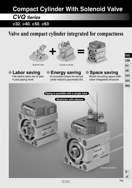
Compact Cylinder With Solenoid Valve
Solenoid valve Compact cylinder
Valve and compact cylinder integrated for compactness
(Mounting example)
Labor saving• No need to select size of valve• Less piping work
Energy savingAir consumption between the valve and cylinder reduced by approximately 50%.
Space savingSmall mounting space with valve integrated structure
ø32, ø40, ø50, ø63
725
CVQ
CVQM
CVJ
CVM
CV3
CVS1
MVGQ
D-
-X
CVQ
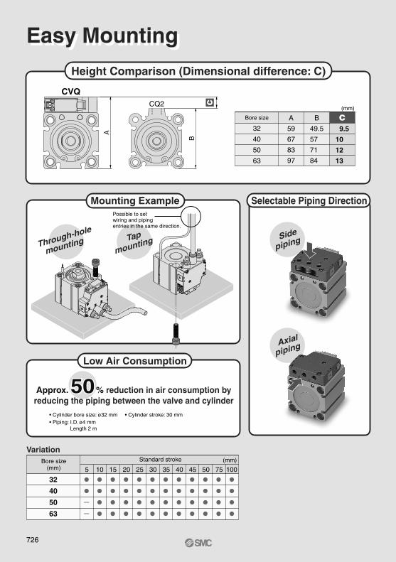
Selectable Piping DirectionMounting ExampleC
B
ACQ2
CVQ
32
40
50
63
A
59
67
83
97
B
49.5
57
71
84
C 9.5
10
12
13
(mm)
Bore size
5
32
40
50
63
••
••••
••••
••••
••••
••••
••••
••••
••••
••••
••••
••••
10 15 20 25 30 35 40 45 50 75 100
Height Comparison (Dimensional difference: C)
Easy MountingEasy Mounting
Side
piping
Axial
piping
• Cylinder bore size: ø32 mm • Cylinder stroke: 30 mm• Piping: I.D. ø4 mm Length 2 m
50Approx. 50% reduction in air consumption byreducing the piping between the valve and cylinder
Variation(mm)Bore size
(mm)Standard stroke
Through-hole
mounting Tap
mounting
Low Air Consumption
Possible to set wiring and piping entries in the same direction.
726
∗1 Water resistant type auto switches can be mounted on the above models, but in such case SMC cannot guarantee water resistance.Consult with SMC regarding water resistant types with the above model numbers.
∗2 1 m type lead wire is only applicable to D-A93.
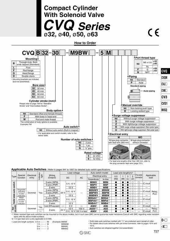
CVQ B 32 30 M9BW
∗ For lead wire lengths other than 300 mm, refer to the plug connector lead wire (page 731).
∗ Lead wire length symbols: 0.5 m ·········· Nil (Example) M9NW 1 m ··········· M M9NWM 3 m ··········· L M9NWL
5 m ··········· Z M9NWZ
Applicable Auto Switches / Refer to pages 941 to 1067 for detailed auto switch specifications.
Bore size32405063
32 mm40 mm50 mm63 mm
Surge voltage suppressorNilSZRU
Without surge voltage suppressorWith surge voltage suppressor
With light/surge voltage suppressorWith surge voltage suppressor (Non-polar type)With light/surge voltage suppressor (Non-polar type)
Manual overrideNilB
Port thread type
Nil
FN
M5 x 0.8
RcG
NPT
ø32ø40
Axial piping
Standard piping
5 M
ø32, ø40, ø50, ø63
Compact CylinderWith Solenoid Valve
CVQ SeriesHow to Order
Mounting
B
LFGD
Through-hole, Bothends tapped (Standard)
FootRod flangeHead flangeDouble clevis
∗ Mounting brackets are included, (but not assembled).
Cylinder stroke (mm)Please refer to page 728 for “Standard Stroke” and “Intermediate Stroke”.
Body optionStandard (Rod end female thread)
With boss in head endRod end male thread
NilFM
The combination of body options is available.Example) FM
Auto switchNil Without auto switch (Built-in magnet)
∗ For applicable auto switch models, refer to the below table.
Number of auto switchesNilSN
2 pcs.1 pc.
“n” pcs.
Rated voltage56
24 VDC12 VDC
PipingNilP
StandardAxial
Electrical entryM
M-type plug connectorwith lead wire (300 mm)
MOM-type plug connector
without connector
ø50ø63
Non-locking push typeLocking slotted type
∗ Solid state auto switches marked with “” are produced upon receipt of order.∗ For details about auto switches with pre-wired connector, refer to pages 1014 and
1015.∗ Auto switches are shipped together (not assembled).
Specialfunction
Wiring(Output)
Load voltage
DC AC
Auto switch model
Electrical entry
Perpendicular In-line
Lead wire length(m)∗
0.5(Nil)
3(L)
5(Z)
Applicableload
Pre-wiredconnector1
(M)
Electricalentry
Reed
auto
switc
hS
olid
sta
te a
uto
switc
h
IC circuit—
IC circuit
Relay,PLC
Relay,PLC
——
———
———
A96A93A90
A96VA93V∗2
A90V
—100 V
100 V or less
—
5 V12 V
5 V, 12 V
24 V
—
24 V
3-wire (NPN equivalent)
2-wire
IC circuit
—
IC circuit
—
IC circuit
—
M9NM9PM9B
M9NWM9PWM9BW
M9NA∗1
M9PA∗1
M9BA∗1
M9NVM9PVM9BV
M9NWVM9PWVM9BWV
M9NAV∗1
M9PAV∗1
M9BAV∗1
5 V, 12 V
12 V
5 V, 12 V
12 V
5 V, 12 V
12 V
3-wire (NPN)3-wire (PNP)
2-wire3-wire (NPN)3-wire (PNP)
2-wire3-wire (NPN)3-wire (PNP)
2-wire
Yes
YesGrommet
—
Diagnosticindication
2-colorindicatorWater
resistant2-color
indicator
Grommet
Type
Indi
cato
rlig
ht
727
CVQ
CVQM
CVJ
CVM
CV3
CVS1
MVGQ
D-
-X
CVQ
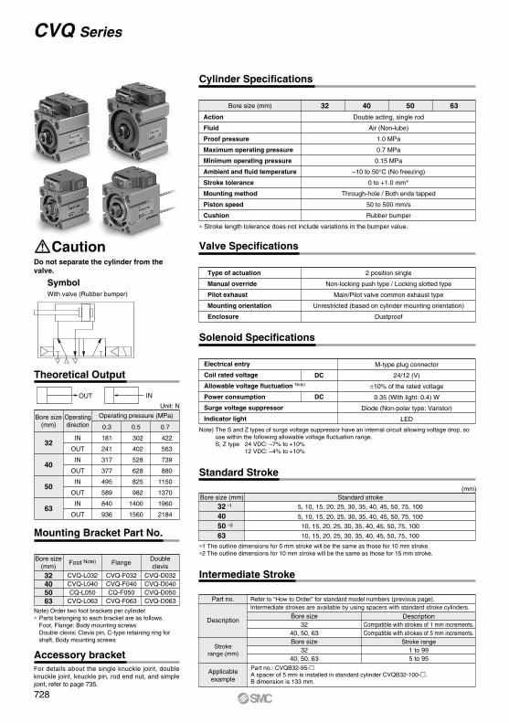
Action
Fluid
Proof pressure
Maximum operating pressure
Minimum operating pressure
Ambient and fluid temperature
Stroke tolerance
Mounting method
Piston speed
Cushion
Double acting, single rod
Air (Non-lube)
1.0 MPa
0.7 MPa
0.15 MPa
–10 to 50°C (No freezing)
0 to +1.0 mm∗
Through-hole / Both ends tapped
50 to 500 mm/s
Rubber bumper
Type of actuation
Manual override
Pilot exhaust
Mounting orientation
Enclosure
2 position single
Non-locking push type / Locking slotted type
Main/Pilot valve common exhaust type
Unrestricted (based on cylinder mounting orientation)
Dustproof
32405063
CVQ-L032CVQ-L040CQ-L050
CVQ-L063
CVQ-F032CVQ-F040CQ-F050
CVQ-F063
CVQ-D032CVQ-D040CVQ-D050CVQ-D063
Note) Order two foot brackets per cylinder.∗ Parts belonging to each bracket are as follows.
Foot, Flange: Body mounting screws Double clevis: Clevis pin, C-type retaining ring for shaft, Body mounting screws
Theoretical Output
OUT IN
32
40
50
63
IN
OUT
IN
OUT
IN
OUT
IN
OUT
Bore size(mm) 0.3
Operatingdirection 0.5
Operating pressure (MPa)
0.7
181
241
317
377
495
589
840
936
302
402
528
628
825
982
1400
1560
422
563
739
880
1150
1370
1960
2184
DC
DC
32 40 50 63Bore size (mm)
Part no.
Applicableexample
Description
Strokerange (mm)
Bore size32
40, 50, 63
Stroke range1 to 995 to 95
Bore size32
40, 50, 63
Refer to “How to Order” for standard model numbers (previous page).Intermediate strokes are available by using spacers with standard stroke cylinders.
Part no.: CVQB32-95- A spacer of 5 mm is installed in standard cylinder CVQB32-100-.B dimension is 133 mm.
(mm)Bore size (mm) Standard stroke
5, 10, 15, 20, 25, 30, 35, 40, 45, 50, 75, 100
5, 10, 15, 20, 25, 30, 35, 40, 45, 50, 75, 100
10, 15, 20, 25, 30, 35, 40, 45, 50, 75, 100
10, 15, 20, 25, 30, 35, 40, 45, 50, 75, 100
32 ∗1
4050 ∗2
63
Cylinder Specifications
Valve Specifications
Solenoid Specifications
M-type plug connector
24/12 (V)
±10% of the rated voltage
0.35 (With light: 0.4) W
Diode (Non-polar type: Varistor)
LED
Electrical entry
Coil rated voltage
Allowable voltage fluctuation Note)
Power consumption
Surge voltage suppressor
Indicator light
Note) The S and Z types of surge voltage suppressor have an internal circuit allowing voltage drop, so use within the following allowable voltage fluctuation range.S, Z type 24 VDC: –7% to +10% 12 VDC: –4% to +10%
Intermediate Stroke
Description
CautionDo not separate the cylinder from the valve.
SymbolWith valve (Rubber bumper)
Mounting Bracket Part No.
Bore size(mm)
Foot Note) FlangeDoubleclevis
Unit: N
Standard Stroke
∗ Stroke length tolerance does not include variations in the bumper value.
Compatible with strokes of 1 mm increments.Compatible with strokes of 5 mm increments.
∗1 The outline dimensions for 5 mm stroke will be the same as those for 10 mm stroke.∗2 The outline dimensions for 10 mm stroke will be the same as those for 15 mm stroke.
CVQ Series
Accessory bracketFor details about the single knuckle joint, double knuckle joint, knuckle pin, rod end nut, and simple joint, refer to page 735.
728
32
40
50
63
Stroke
5295
365
—
—
10288
391
735
863
15310
417
721
905
20332
443
760
947
25354
469
800
990
30 376
495
839
1032
35 398
521
879
1074
40 420
547
918
1116
45 442
573
958
1158
50 464
599
997
1200
75 575
726
1195
1411
100 686
853
1392
1621
Unit (g)
Bore size (mm)
Axial piping
Connector (300 mm)
Rod end male thread
With boss in head end
Foot (including mounting bolt)
Rod flange (including mounting bolt)
Head flange (including mounting bolt)
Double clevis (including pin, retaining ring, bolt)
Male thread
Nut
5
3
27
17
7
160
219
203
201
404
3
53
32
13
243
373
348
399
504
3
53
32
25
334
569
544
574
635
3
26
17
5
148
185
170
156
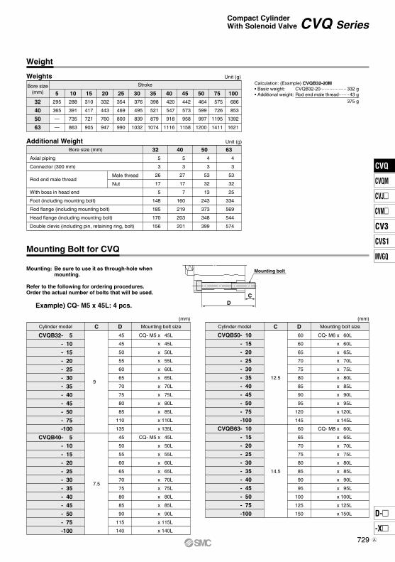
32Additional Weight
DC
Mounting bolt
Cylinder model C D Mounting bolt size
9
7.5
CQ- M5 x 45L
x 45L
x 50L
x 55L
x 60L
x 65L
x 70L
x 75L
x 80L
x 85L
x 110L
x 135L
CQ- M5 x 45L
x 50L
x 55L
x 60L
x 65L
x 70L
x 75L
x 80L
x 85L
x 90L
x 115L
x 140L
45
45
50
55
60
65
70
75
80
85
110
135
45
50
55
60
65
70
75
80
85
90
115
140
CVQB32- 5
- 10
- 15
- 20
- 25
- 30
- 35
- 40
- 45
- 50
- 75
-100
CVQB40- 5
- 10
- 15
- 20
- 25
- 30
- 35
- 40
- 45
- 50
- 75
-100
(mm)
Cylinder model C D Mounting bolt size
12.5
14.5
CQ- M6 x 60L
x 60L
x 65L
x 70L
x 75L
x 80L
x 85L
x 90L
x 95L
x 120L
x 145L
CQ- M8 x 60L
x 65L
x 70L
x 75L
x 80L
x 85L
x 90L
x 95L
x 100L
x 125L
x 150L
60
60
65
70
75
80
85
90
95
120
145
60
65
70
75
80
85
90
95
100
125
150
CVQB50- 10
- 15
- 20
- 25
- 30
- 35
- 40
- 45
- 50
- 75
-100
CVQB63- 10
- 15
- 20
- 25
- 30
- 35
- 40
- 45
- 50
- 75
-100
(mm)
Bore size(mm)
Weights
Weight
Unit (g)Calculation: (Example) CVQB32-20M• Basic weight: CVQB32-20 ···················· 332 g• Additional weight: Rod end male thread ········ 43 g
375 g
Mounting Bolt for CVQ
Mounting: Be sure to use it as through-hole when mounting.
Refer to the following for ordering procedures.Order the actual number of bolts that will be used.
Example) CQ- M5 x 45L: 4 pcs.
CVQ SeriesCompact CylinderWith Solenoid Valve
729
CVQ
CVQM
CVJ
CVM
CV3
CVS1
MVGQ
D-
-X
CVQ
A
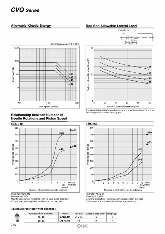
Restrictor: ASN2-M5Pressure: 0.5 MPaMounting orientation: Horizontal, with no load, piston extended∗ The above piston speed is for reference purpose only.
Pis
ton
spee
d (m
m/s
)
Number of restrictor’s needle rotations
400
300
200
100
500
600
700
800
10 1 2 3 4 5 6
ø32ø32
ø40ø40
<Exhaust restrictor with silencer >
Model Port size
M5 x 0.8
1/8
Effective area (mm2)
1.8
3.6
Weight (g)
5
17
ASN2-M5
ASN2-01
32, 40
50, 63
ø32, ø40 ø50, ø63
10000
1000
100
10
110 100 1000
Operating pressure: 0.5 MPa
Load
mas
s (N
)
Max. speed (mm/s)
ø63ø50ø40
ø32
100
10
10 20 40 60 80 100
Stroke + Eccentric distance (mm)
Rod
end
allo
wab
le la
tera
l loa
d (N
)
ø63
ø50
ø40
ø32
800
700
600
500
400
300
200
100
00 1 2 3 4 5 6 7 8 9 10
Fullyopened
Pis
ton
spee
d (m
m/s
)
ø50
ø50
ø63
ø63
The allowable lateral load applied to the rod end is as shown above. Do not use exceeding the value shown by the graph.
Allowable Kinetic Energy Rod End Allowable Lateral Load
CVQ Series
Stroke
Lateral load
Eccentricdistance
Relationship between Number of Needle Rotations and Piston Speed
7Fullyopened
Withoutrestrictor
Restrictor: ASN2-01Pressure: 0.5 MPaMounting orientation: Horizontal, with no load, piston extended∗ The above piston speed is for reference purpose only.
Number of restrictor’s needle rotations
Withoutrestrictor
Applicable bore size (mm)
730
1
2
3
4
5
6
7
8
9
10
11
12
13
14
15
16
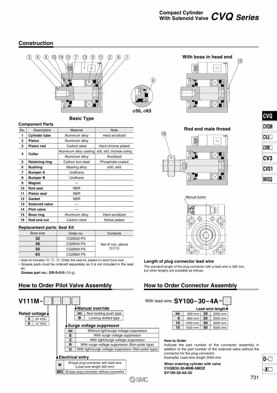
DescriptionNo. Material
Component Parts
Cylinder tube
Piston
Piston rod
Collar
Retaining ring
Bushing
Bumper A
Bumper B
Magnet
Rod seal
Piston seal
Gasket
Solenoid valve
Pilot valve
Boss ring
Rod end nut
Aluminum alloy
Aluminum alloy
Carbon steel
Aluminum alloy casting
Aluminum alloy
Carbon tool steel
Bearing alloy
Urethane
Urethane
—
NBR
NBR
NBR
—
—
Aluminum alloy
Carbon steel
Note
Hard anodized
Hard chrome plated
ø50, ø63, chromate coating
Anodized
Phosphate coated
ø50, ø63
Hard anodized
Nickel plated
Contents
Set of nos. above!0!1!2
Order no.
CQ2B32-PS
CQ2B40-PS
CQ2B50-PS
CQ2B63-PS
Bore size
32405063
Replacement parts: Seal Kit
With lead wire: SY100 30 4ALead wire length
Nil 61015
300 mm600 mm
1000 mm1500 mm
20253050
2000 mm2500 mm3000 mm5000 mm
V111M
With boss in head end
Rod end male thread
Manual button
ø50, ø63
e r t !0 !4 !2 u !3 o !1 w i q
!6
y
!5
Construction
How to Order Pilot Valve Assembly
Rated voltage56
24 VDC12 VDC
Electrical entry
M
MO
M-type plug connector with lead wire(Lead wire length 300 mm)
M-type plug connector without connector
Manual overrideNilB
Non-locking push typeLocking slotted type
Surge voltage suppressorNilSZRU
Without light/surge voltage suppressorWith surge voltage suppressor
With light/surge voltage suppressorWith surge voltage suppressor (Non-polar type)
With light/surge voltage suppressor (Non-polar type)
When ordering cylinder with valveCVQB32-30-M9B-5MOZSY100-30-4A-20
How to OrderIndicate the part number of the connector assembly in addition to the part number of the solenoid valve without the connector for the plug connector.Example) Lead wire length 2000 mm
Length of plug connector lead wireThe standard length of the plug connector with a lead wire is 300 mm, but other lengths are available as follows.
How to Order Connector Assembly
Basic Type
∗ Seal kit includes !0, !1, !2. Order the seal kit, based on each bore size.∗ Grease pack must be ordered separately as it is not included in the seal
kit.Grease part no.: GR-S-010 (10 g)
CVQ SeriesCompact CylinderWith Solenoid Valve
731
CVQ
CVQM
CVJ
CVM
CV3
CVS1
MVGQ
D-
-X
CVQ
Q SS
F P1
øD
L
øT
h9
2F
1
32405063
Th9
Bore size(mm)
32405063
F1
30
34.5
43.5
51
(mm)
Bore size(mm)
32405063
C1
20.5
20.5
26
26
H1
8
8
11
11
B1
22
22
27
27
L1
28.5
28.5
33.5
33.5
MM
M14 x 1.5
M14 x 1.5
M18 x 1.5
M18 x 1.5
X
23.5
23.5
28.5
28.5
(mm)
Bore size(mm)
Stroke range(mm)
32405063
5 to 100
5 to 100
10 to 100
10 to 100
S
12
12
17
17
V
43
43
54
54
RB
7
7
8
10.5
RA
10
10
14
18
W
43.5
43.5
63
63
Y
59
67
83
97
Bore size(mm)
Stroke range(mm)
32405063
A
40 Note 1)
46.5
48.5 Note 2)
54
5 to 100
5 to 100
10 to 100
10 to 100
B
33 Note 1)
39.5
40.5 Note 2)
46
C
13
13
15
15
D
16
16
20
20
E
45
52
64
77
F
6.5
6.5
7.5
7.5
H
M8 x 1.25
M8 x 1.25
M10 x 1.5
M10 x 1.5
J
22.5
26
32
38.5
L
7
7
8
8
K
14
14
17
17
M
34
40
50
60
N
5.4
5.4
6.6
9
OA
M6 x 1
M6 x 1
M8 x 1.25
M10 x 1.5
OB
9
9
11
14
P1
M5 x 0.8
M5 x 0.8
Rc, G, NPT1/8
Rc, G, NPT1/8
P2
M5 x 0.8
M5 x 0.8
Rc, G, NPT1/8
Rc, G, NPT1/8
Q
2.5
2.5
3.5
3.5
(mm)
Y
W
K
M
E
M
J
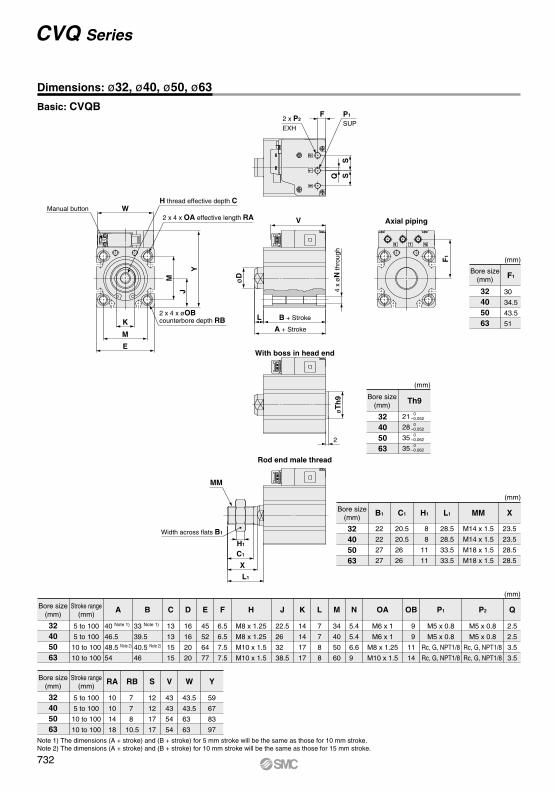
Dimensions: ø32, ø40, ø50, ø63
Basic: CVQB
CVQ Series
2 x 4 x øOB counterbore depth RB
2 x 4 x OA effective length RA
H thread effective depth CManual button
2 x P2
EXHSUP
With boss in head end
Axial piping
4 x
øN
thro
ugh
B + Stroke
A + Stroke
Bore size(mm)
(mm)
21
28
35
35
0–0.0520
–0.0520
–0.0620
–0.062
Note 1) The dimensions (A + stroke) and (B + stroke) for 5 mm stroke will be the same as those for 10 mm stroke. Note 2) The dimensions (A + stroke) and (B + stroke) for 10 mm stroke will be the same as those for 15 mm stroke.
Rod end male thread
MM
Width across flats B1
C1
H1
X
L1
V
732
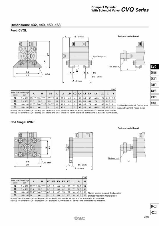
Dimensions: ø32, ø40, ø50, ø63
Foot: CVQL
Rod flange: CVQF
Rod end male thread
Rod end male thread
FT
L B + Stroke
A + Stroke
L1
Rod end nut
FVM
FZ
FX 4 x øFD
LT
LGXYYX
LS + Stroke
A + Stroke
B + StrokeL
Special cap bolt
L1
Rod end nut
LY
LX
LH
LZ4 x øLD
Bore size(mm)
Stroke range(mm)
32405063
A
57.2 Note 1)
63.7
66.7 Note 2)
72.2
5 to 100
5 to 100
10 to 100
10 to 100
B
33 Note 2)
39.5
40.5 Note 2)
46
LS
17 Note 1)
23.5
17.5 Note 2)
20
L
17
17
18
18
L1
38.5
38.5
43.5
43.5
LD
6.6
6.6
9
11
LG
4
4
5
5
LH
30
33
39
46
LT
3.2
3.2
3.2
3.2
LX LY
57
64
79
95
66.5
74
90
104.5
LZ
71
78
95
113
X
11.2
11.2
14.7
16.2
Y
5.8
7
8
9
(mm)
Bore size(mm)
Stroke range(mm)
32405063
A
50 Note 1)
56.5
58.5 Note 2)
64
5 to 100
5 to 100
10 to 100
10 to 100
B
33 Note 1)
39.5
40.5 Note 2)
46
FD
5.5
5.5
6.6
9
FT
8
8
9
9
FX
56
62
76
92
FV
48
54
67
80
FZ
65
72
89
108
L
17
17
18
18
L1
38.5
38.5
43.5
43.5
M
34
40
50
60
(mm)
Foot bracket material: Carbon steelSurface treatment: Nickel plated
Flange bracket material: Carbon steelSurface treatment: Nickel plated
Note 1) The dimensions (A + stroke), (B + stroke) and (LS + stroke) for 5 mm stroke will be the same as those for 10 mm stroke. Note 2) The dimensions (A + stroke), (B + stroke) and (LS + stroke) for 10 mm stroke will be the same as those for 15 mm stroke.
Note 1) The dimensions (A + stroke) and (B + stroke) for 5 mm stroke will be the same as those for 10 mm stroke. Note 2) The dimensions (A + stroke) and (B + stroke) for 10 mm stroke will be the same as those for 15 mm stroke.
CVQ SeriesCompact CylinderWith Solenoid Valve
733
CVQ
CVQM
CVJ
CVM
CV3
CVS1
MVGQ
D-
-X
CVQ
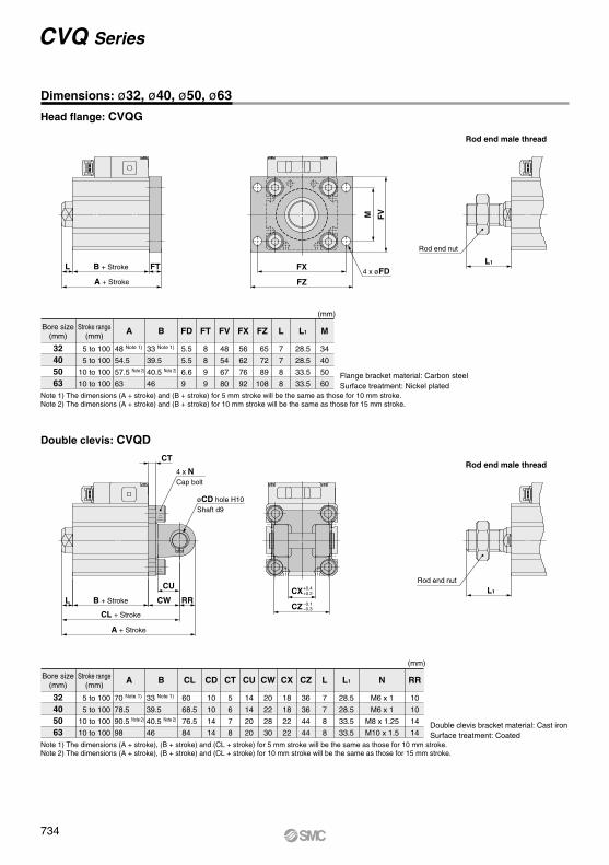
Double clevis: CVQD
Rod end male thread
FTL B + Stroke
A + Stroke
FVM
FZ
FX4 x øFD
L1
Rod end nut
CT
CU
RRCWL B + Stroke
CL + Stroke
A + Stroke
Cap bolt
Shaft d9øCD hole H10
4 x N
L1
Rod end nut
CX
CZ –0.1–0.3
+0.4+0.2
Bore size(mm)
Stroke range(mm)
32405063
A
48 Note 1)
54.5
57.5 Note 2)
63
5 to 100
5 to 100
10 to 100
10 to 100
B
33 Note 1)
39.5
40.5 Note 2)
46
FD
5.5
5.5
6.6
9
FT
8
8
9
9
FV
48
54
67
80
FX
56
62
76
92
FZ
65
72
89
108
L
7
7
8
8
L1
28.5
28.5
33.5
33.5
M
34
40
50
60
(mm)
Bore size(mm)
Stroke range(mm)
32405063
A
70 Note 1)
78.5
90.5 Note 2)
98
5 to 100
5 to 100
10 to 100
10 to 100
B
33 Note 1)
39.5
40.5 Note 2)
46
CL
60
68.5
76.5
84
CD
10
10
14
14
CT
5
6
7
8
CU
14
14
20
20
CW
20
22
28
30
CX
18
18
22
22
CZ
36
36
44
44
L
7
7
8
8
L1 N
28.5
28.5
33.5
33.5
M6 x 1
M6 x 1
M8 x 1.25
M10 x 1.5
RR
10
10
14
14
(mm)
Note 1) The dimensions (A + stroke) and (B + stroke) for 5 mm stroke will be the same as those for 10 mm stroke. Note 2) The dimensions (A + stroke) and (B + stroke) for 10 mm stroke will be the same as those for 15 mm stroke.
Note 1) The dimensions (A + stroke), (B + stroke) and (CL + stroke) for 5 mm stroke will be the same as those for 10 mm stroke. Note 2) The dimensions (A + stroke), (B + stroke) and (CL + stroke) for 10 mm stroke will be the same as those for 15 mm stroke.
CVQ Series
Dimensions: ø32, ø40, ø50, ø63
Head flange: CVQG
Rod end male thread
Flange bracket material: Carbon steelSurface treatment: Nickel plated
Double clevis bracket material: Cast ironSurface treatment: Coated
734
U
E
2 x øD
FB
T1
T2 V M W
T1
B EJ
RS
2 x øD through2 x øO counterbore
V M WT2
IY-G04IY-G05
Part no. L
41.650.6
d
9.613.4
L1
36.244.2
m
1.552.05
t
1.151.15
Applicablebore size (mm) Retaining ring
32, 4050, 63
NT-04NT-05
Part no. Applicablebore size (mm)
32, 4050, 63
d
M14 x 1.5M18 x 1.5
H
811
B
2227
C
25.431.2
10 C-type for shaft14 C-type for shaft
10–0.040–0.076
14–0.050–0.093
Dd9
ø
I-G04I-G05
Part no. A
4256
A1
1418
E1
ø22ø28
L1
3040
MM
M14 x 1.5M18 x 1.5
RR1
1216
U1
1420
NDH10 NXApplicablebore size
(mm)
32, 4050, 63
10+0.0580 18–0.3
–0.5
14+0.0700 22–0.3
–0.5
Y-G04Y-G05
Material: Cast iron(mm)
Material: Cast iron(mm)
Part no. A
4256
A1
1620
E1
ø22ø28
L1
3040
NZ
3644
L
41.650.6
MM
M14 x 1.5M18 x 1.5
RR1
1216
U1
1420
NDH10 NXApplicable
pinpart no.
32, 4050, 63
10+0.0580
14+0.0700
18 IY-G04IY-G05
+0.5+0.3
22+0.5+0.3
Applicablebore size
(mm)
øø
L1
B-type mounting bracket
Part no.
YA-03YA-05
Bore size(mm)
32, 4050, 63
B
1820
D
6.89
E
1620
F
68
M
4250
T1
6.56.5
T2
1012
Part no.
YA-03YA-05
Bore size(mm)
32, 4050, 63
U
68
V
1822
W
5667
Weight (g)
55100
Material: Carbon steel(Nickel plated)
(mm)
Part no.
32, 4050, 63
1212
80120
B D
79
E
2532
J
911
M
3442
øO
11.5 depth 7.514.5 depth 8.5
Bore size(mm)
Part no.
YB-03YB-05
32, 4050, 63
T1
6.56.5
T2
1012
V
1822
W
5060
RS
911
Weight (g)Bore size(mm)
YB-03YB-05
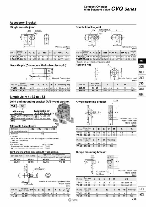
Joint and mounting bracket (A/B-type) part no.
YA 03
Mountingbracket
YAYBYU
A-type mounting bracketB-type mounting bracket
Joint
0305
For ø32, ø40For ø50, ø63
Allowable Eccentricity (mm)
Material: Chromium molybdenum steel(Nickel plated)
(mm)
Bore sizeEccentricity toleranceBacklash
ø32 ø40 ø50 ø63±10.5
Joint and mounting bracket (A/B-type) part no.
Bore size (mm)
32, 4050, 63
Joint part no.
YU-03YU-05
Applicable mounting bracketA-type mounting bracket
YA-03YA-05
B-type mounting bracket
YB-03YB-05
Part no. Applicablebore size (mm) UA C d1 d2 H K L UT Weight
(g)
2540
YU-03YU-05
1717
1113
15.819.8
1418
M8 x 1.25M10 x 1.5
810
77
66
32, 4050, 60
H
CUA
LUT
K (
Wid
thac
ross
flat
s ø
)
ød
2
ød
1
(With locking)
Material: Chromiummolybdenum steel
(Nickel plated)(mm)
BH
C
d
Material: Carbon steel(mm)
Material: Carbon steel(mm)
Double knuckle joint
Knuckle pin (Common with double clevis pin) Rod end nut
A-type mounting bracket
Simple Joint / ø32 to ø63
Applicable aircylinder bore size
∗ Knuckle pin and retaining ring are included.
<Ordering>• Joints are not included with the A- or B-type mounting brackets.
Order them separately.(Example)Bore size for ø40 Order number• A-type mounting bracket part number ······· YA-03• Joint ·························································· YU-03
CVQ SeriesCompact CylinderWith Solenoid Valve
Accessory Bracket
Single knuckle joint
Shaft d9øND hole H10
735
CVQ
CVQM
CVJ
CVM
CV3
CVS1
MVGQ
D-
-X
CVQ
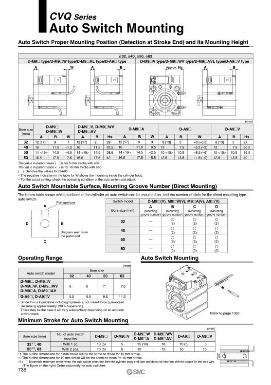
Operating Range Auto Switch Mounting
Minimum Stroke for Auto Switch Mounting
Auto Switch Mountable Surface, Mounting Groove Number (Direct Mounting)The below table shows which surfaces of the cylinder an auto switch can be mounted on, and the number of slots for the direct mounting type auto switch.
ø32, ø40, ø50, ø63D-M9 type/D-M9W type/D-M9AL type/D-A9 type D-M9V type/D-M9WV type/D-M9AVL type/D-A9V type
D-M9A
12 [17]
16
14 <19>
16.5
9
11.5
14.5
17.5
3
0.5
–2.5
–5.5
A B W
(mm)
Bore size(mm)
32405063
12 [17]
16
14 <19>
16.5
9
11.5
14.5
17.5
29
32.5
38.5
42
12 [17]
16
14 <19>
16.5
9
11.5
14.5
17.5
D-M9D-M9W
D-M9V, D-M9WVD-M9AV
8 [13]
12
10 <15>
12.5
8 [13]
12
10 <15>
12.5
5
7.5
10.5
13.5
5
7.5
10.5
13.5
27
30.5
36.5
40
D-A9VD-A9
A BA B–3 (–0.5)
–5.5 (–3)
–8.5 (–6)
–11.5 (–9)
W HsA B1
–1.5
–4.5
–7.5
W A B Hs
D-A9, D-A9V
D-M9, D-M9VD-M9W, D-M9WVD-M9A, D-M9AV
Auto switch modelBore size
(mm)
32 40
6
9.5
6
9.5
50
7
9.5
63
7.5
11.5
∗ Since this is a guideline including hysteresis, not meant to be guaranteed. (Assuming approximately ±30% dispersion.)There may be the case it will vary substantially depending on an ambient environment.
∗1 The outline dimensions for 5 mm stroke will be the same as those for 10 mm stroke.∗2 The outline dimensions for 10 mm stroke will be the same as those for 15 mm stroke.∗3 ( ): Mountable minimum stroke when the auto switch protrudes from the cylinder body end face and does not interfere with the space for the lead wire. (The figure on the right) Order separately for auto switches.
Switch model D-M9(V), M9W(V), M9A(V), A9(V)
Bore size (mm)A
(Mountinggroove number)
B(Mounting
groove number)
C(Mounting
groove number)
D(Mounting
groove number)
32
40
— (2)
(2)
(2)
— (2)
(2)
(2)
50 — (2)
(2)
(2)
63 — (2)
(2)
(2)
A
C
D B
Port aperture
Diagram seen from the piston rod
A W A B Approx. Hs A B
The value in parentheses [ ] is for 5 mm stroke with ø32.The value in parentheses < > is for 10 mm stroke with ø50.( ): Denotes the values for D-A93.∗ The negative indication in the table for W shows the mounting inside the cylinder body.∗ For the actual setting, check the operating condition of the auto switch and adjust.
Auto Switch Proper Mounting Position (Detection at Stroke End) and Its Mounting Height
Refer to page 1062.
Bore size (mm)
32∗1, 4050∗2, 63
D-A9
10 (5)
10
(mm)
No. of auto switchmounted
With 1 pc.
With 2 pcs.
D-A9V
5
10
D-M9
10 (5)
10 (5)
D-M9V
5
5
D-M9WD-M9A
15 (10)
15
D-M9WVD-M9AV
10
15
CVQ Series
Auto Switch Mounting
736
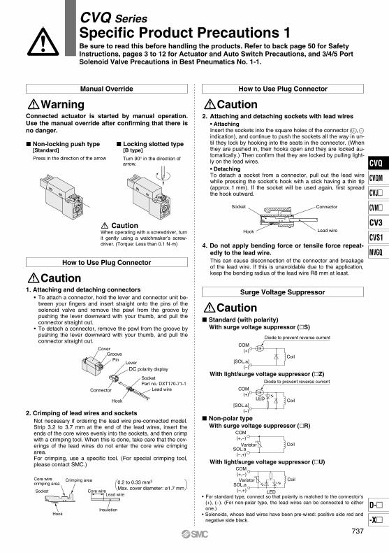
Non-locking push type [Standard]
Locking slotted type [B type]
Turn 90° in the direction of arrow.
Press in the direction of the arrow
Connected actuator is started by manual operation. Use the manual override after confirming that there is no danger.
Manual Override
Warning
CautionWhen operating with a screwdriver, turn it gently using a watchmaker’s screw-driver. (Torque: Less than 0.1 N·m)
1. Attaching and detaching connectors• To attach a connector, hold the lever and connector unit be-
tween your fingers and insert straight onto the pins of the solenoid valve and remove the pawl from the groove by pushing the lever downward with your thumb, and pull the connector straight out.
• To detach a connector, remove the pawl from the groove by pushing the lever downward with your thumb, and pull the connector straight out.
How to Use Plug Connector
Caution
2. Crimping of lead wires and sockets Not necessary if ordering the lead wire pre-connected model. Strip 3.2 to 3.7 mm at the end of the lead wires, insert the ends of the core wires evenly into the sockets, and then crimp with a crimping tool. When this is done, take care that the cov-erings of the lead wires do not enter the core wire crimping area.For crimping, use a specific tool. (For special crimping tool, please contact SMC.)
Lead wire Socket
Crimping areaCore wire crimping area
HookInsulation
Core wire
0.2 to 0.33 mm2
Max. cover diameter: ø1.7 mm
2. Attaching and detaching sockets with lead wires• Attaching Insert the sockets into the square holes of the connector ( , indication), and continue to push the sockets all the way in un-til they lock by hooking into the seats in the connector. (When they are pushed in, their hooks open and they are locked au-tomatically.) Then confirm that they are locked by pulling light-ly on the lead wires.• DetachingTo detach a socket from a connector, pull out the lead wire while pressing the socket’s hook with a stick having a thin tip (approx. 1 mm). If the socket will be used again, first spread the hook outward.
How to Use Plug Connector
Caution
Connector
Lead wire
Socket
Hook
4. Do not apply bending force or tensile force repeat-edly to the lead wire.This can cause disconnection of the connector and breakage of the lead wire. If this is unavoidable due to the application, keep the bending radius of the lead wire R8 mm at least.
Surge Voltage Suppressor
Caution Standard (with polarity)
With surge voltage suppressor (S)
With light/surge voltage suppressor (Z)
Non-polar typeWith surge voltage suppressor (R)
With light/surge voltage suppressor (U)
• For standard type, connect so that polarity is matched to the connector’s (+), (–). (For non-polar type, the lead wires can be connected to either one.)
• Solenoids, whose lead wires have been pre-wired: positive side red and negative side black.
-+ SocketPart no. DXT170-71-1
Hook
Lead wire
DC polarity displayLever
Connector
PinGroove
Cover
CVQ SeriesSpecific Product Precautions 1Be sure to read this before handling the products. Refer to back page 50 for Safety Instructions, pages 3 to 12 for Actuator and Auto Switch Precautions, and 3/4/5 Port Solenoid Valve Precautions in Best Pneumatics No. 1-1.
[SOL.a](−)
COM(+)
Diode to prevent reverse current
Coil
CoilLED
Diode to prevent reverse current
[SOL.a](−)
COM(+)
CoilVaristorSOL.a
(−,+)
COM(+,−)
Varistor
LED
CoilSOL.a
(−,+)
COM(+,−)
737
CVQ
CVQM
CVJ
CVM
CV3
CVS1
MVGQ
D-
-X
CVQ

Mounting/Removal
Caution
1. To remove and install the retaining ring, use an ap-propriate pair of pliers (tool for installing C-type re-taining ring).
2. Even if a proper plier (tool for installing C-type re-taining ring) is used, it is likely to inflict damage to a human body or peripheral equipment, as a retain-ing ring may be flown out of the tip of a plier (tool for installing C-type retaining ring). Be much careful with the popping of a retaining ring. Besides, be certain that a retaining ring is placed firmly into the groove of rod cover before supplying air at the time of installment.
Retaining Ring Installation/Removal
Caution
1. Do not separate the cylinder from the valve.
1. Do not remove the plug from the cylinder tube end surface.If the plug is removed with compressed air supplied to the cylinder, the air blowing out may inflict dam-age to a human body or peripheral equipment.
Other
Caution
CVQ SeriesSpecific Product Precautions 2Be sure to read this before handling the products. Refer to back page 50 for Safety Instructions, pages 3 to 12 for Actuator and Auto Switch Precautions, and 3/4/5 Port Solenoid Valve Precautions in Best Pneumatics No. 1-1.
738