comparative study of performance of conventional …etabs 2015. to study the behavior of the...
TRANSCRIPT
INTERNATIONAL RESEARCH JOURNAL OF ENGINEERING AND TECHNOLOGY (IRJET) E-ISSN: 2395 -0056
VOLUME: 03 ISSUE: 10 | OCT -2016 WWW.IRJET.NET P-ISSN: 2395-0072
© 2016, IRJET | Impact Factor value: 4.45 | ISO 9001:2008 Certified Journal | Page 639
Comparative Study of Performance of Conventional R.C Framed Structures and Diagrid Structures Subjected to Ground Motions
Mohammed Ibrahim1, Veena Narayankar2
1M.tech structural engineering student Sambram Institute of Technology Bangalore, India
Abstract: Diagrid members are more effective in carrying gravity loads and lateral forces as well, these members carry lateral forces on their axis which helps in minimizing shear deformations. Usually diagrids members are located in the periphery of the buildings due to which these buildings do not require shear walls or any other systems such as wall frame, braced tube, outrigger system to resist lateral shear. In this study a conventional 31 story R.C building and another three buildings with diagrids having inclination of 36.86o, 56.30o and 66.03o have been modeled as per IS 1893 (part 1) : 2002 provisions and analyzed using Nonlinear static analysis in ETABS 2015. The response parameters of conventional building and buildings with diagrids are studied in terms of story displacement, story drift, diaphragm drift, spectral acceleration, spectral displacement and base shear. It is found that the values of all these parameters are least at a diagrid angle of 66.03o. Hence this angle is regarded as an optimum angle of diagrid at which the building has shown its best performance. Key Words: story displacement, story drift, diaphragm drift, spectral acceleration, spectral displacement, base shear, optimum diagrid angle, Pushover Analysis.
I. INTRODUCTION
The rapid increase in urban population have lead to increase in land value and limited space in the metropolitan cities. To minimize this urban sprawl one of the option is to erect high rise buildings. High rise buildings are more susceptible to ground motions and heavy wind. Diagrids have good appearance. The efficiency and configuration of dia grid will reduce number of structural members required for a building the efficiency in structural system of a diagrids system minimizes the No. of columns and specially the corner columns, and hence provides significant flexibility in the floor plan. The conventional high rise buildings need lateral shear resisting systems such as wall frame systems, braced tube, outrigger system and shear walls etc. to resist lateral shear imposed on them. The diagrids are usually provided in the perimeter of the building which resists gravity and lateral loads effectively through it axis and they don’t need any extra shear resisting systems. Diagrids can also save steel from 20%-30% of the steel as compared to the conventional buildings.
In this study an attempt is made to compare the conventional building with that of buildings with diagrids
inclined at different angles. Various response
parameters of both type of buildings are studied and the optimum angle at which the building’s performance is best is determined.
II. SCOPE OF THE STUDY
1. By studying various parameters of a conventional building subjected to nonlinear static analysis and comparing those with buildings with different diagrids angles the significance of using diagrids in the buildings can be known.
2. Diagrids when used in buildings it improves the aesthetic appearance of the building.
3. 3. Diagrids reduces the total steel consumption in the building as compared to the conventional buildings.
4. 4. Diagrids improves the ductility of the building, and less steel consumption results in achieving economy in designs without compromising the safety and stability of the buildings.
III. OBJECTIVES
To compare the performance of a conventional 31 story R.C building and buildings with diagrids angles 36.86o, 56.30o and 66.03o. Using static Nonlinear analysis in ETABS 2015.
To study the behavior of the conventional building and buildings with diagrids having angles of inclinations 36.86o, 56.30o and 66.03o in terms of parameters such as story displacement, diaphragm drift, story acceleration, base shear and story displacement.
To determine the optimum angle of diagrids at which the building performs its best under the influence of lateral forces imposed on it.

INTERNATIONAL RESEARCH JOURNAL OF ENGINEERING AND TECHNOLOGY (IRJET) E-ISSN: 2395 -0056
VOLUME: 03 ISSUE: 10 | OCT -2016 WWW.IRJET.NET P-ISSN: 2395-0072
© 2016, IRJET | Impact Factor value: 4.45 | ISO 9001:2008 Certified Journal | Page 640
IV. ANALYTICAL WORK
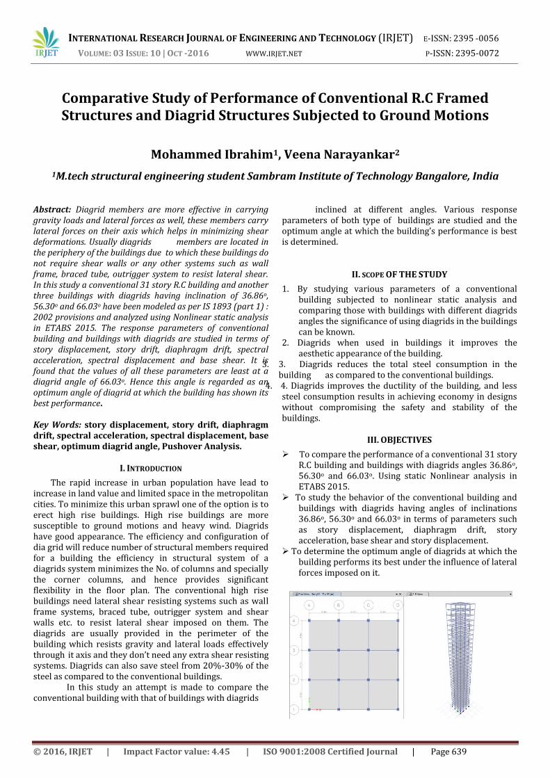
This analytical work is carried out by using ETABS 2015 considering four types of symmetric buildings such as. Model 1: A conventional 31 storied building as shown in Fig 4.1. Model 2: A 31 storied Building with diagrids inclined at 36.860 as shown in Fig 4.2. Model 3: A 31 storied building with diagrids inclined at 56.300 as shown in Fig 4.3. Model 4: A 31 storied building with diagrids inclined at 66.030 as Shown in Fig 4.4. Fig 4.1: plan and 3-D elevation of a 31 storied conventional building.
Fig 4.2: plan and 3-D elevation of a 31 storied building with diagrids angle 36.860
Fig 4.3: plan and 3-D elevation of a 31 storied building with diagrids angle 56.300
Fig 4.4: plan and 3-D elevation of a 31 storied building with diagrids angle 66.030
.
.
2Assistant professor Sambram Institute of Technology Bangalore, India
Fig 4.5: Typical bottom story plan of a 31 storied building with diagrids at different angles.
V . RESULTS AND DISCUSSION Here we have discussed about conventional building, building with diagrids inclined at different angles. The results are obtained in terms of diaphragm drift, spectral acceleration, spectral displacement, base shear vs. monitored displacement and max story displacement.
Diaphragm drifts for the force in push-X direction
Fig 5.1: Graph showing diaphragm drifts. It can be seen that the diaphragm drift is least when the angle of inclination of the diagrids is 66.03o. ie, when the diagrid is spanning in three stories.

INTERNATIONAL RESEARCH JOURNAL OF ENGINEERING AND TECHNOLOGY (IRJET) E-ISSN: 2395 -0056
VOLUME: 03 ISSUE: 10 | OCT -2016 WWW.IRJET.NET P-ISSN: 2395-0072
© 2016, IRJET | Impact Factor value: 4.45 | ISO 9001:2008 Certified Journal | Page 641
Spectral acceleration and spectral displacement for the force in push-X direction.
Fig 5.2: Graph showing spectral displacement vs spectral acceleration values. It can be seen that sd and sa are least when the angle of inclination of the diagrids is 66.03o ie, when the diagrid is spanning in three stories. Base Shear vs Monitored Displacement for the force in push-X direction.
Fig 5.3: Graph showing Base shear vs Monitored displacement values. It can be seen that Base shear and displacement values are least when the angle of inclination of the diagrids is 66.03o ie, when the diagrid is spanning in three stories. Maximum story displacement for push in X-direction Fig 5.4: Graph Maximum displacement values. It can be seen that Maximum displacement values are least when the angle of inclination of the diagrids is 66.03o ie, when the diagrid is spanning in three stories.
Story Acceleration for push in X direction
Fig 5.5: Graph story acceleration values. Its can be seen that story acceleration values are least when the angle of inclination of the diagrids is 66.03o ie, when the diagrid is spanning in three stories.
Diaphragm drifts for the force in push-Y direction
2.0
Fig 5.6: Graph showing diaphragm drifts values. Its can be seen that the diaphragm drift is least when the angle of inclination of the diagrids is 66.03o ie, when the diagrid is spanning in three stories.

INTERNATIONAL RESEARCH JOURNAL OF ENGINEERING AND TECHNOLOGY (IRJET) E-ISSN: 2395 -0056
VOLUME: 03 ISSUE: 10 | OCT -2016 WWW.IRJET.NET P-ISSN: 2395-0072
© 2016, IRJET | Impact Factor value: 4.45 | ISO 9001:2008 Certified Journal | Page 642
Spectral acceleration and spectral displacement for the force in push-Y direction.
5.7: Graph showing spectral displacement vs spectral acceleration values. It can be seen that sd and sa are least when the angle of inclination of the diagrids is 66.03o ie, when the diagrid is spanning in three stories.
Maximum story displacement for push in Y-direction Fig 5.8: Graph Maximum displacement values. It can be seen that Maximum displacement values are least when the angle of inclination of the diagrids is 66.03o ie, when the diagrid is spanning in three stories Base Shear vs Monitored Displacement for the force in push-Y direction. Fig 5.9: Graph showing Base shear vs Monitored displacement values. It can be seen that Base shear and displacement values are least when the angle of inclination of the diagrids is 66.03o ie, when the diagrid is spanning in three stories
Story Acceleration for push in Y direction
Fig 5.10: Graph story acceleration values. It can be seen that story acceleration values are least when the angle of inclination of the diagrids is 66.03o ie, when the diagrid is spanning in three stories.

INTERNATIONAL RESEARCH JOURNAL OF ENGINEERING AND TECHNOLOGY (IRJET) E-ISSN: 2395 -0056
VOLUME: 03 ISSUE: 10 | OCT -2016 WWW.IRJET.NET P-ISSN: 2395-0072
© 2016, IRJET | Impact Factor value: 4.45 | ISO 9001:2008 Certified Journal | Page 643
Table Given below Shows the Difference in shear force (Fy) and bending movement (Mz) between conventional building and building with diagrids
Column No
Fy(kN)(1) Mz(kN-m)(2) Fy(kN)(3) Mz(kN-m)(4) (3/1) (4/2)
1 21.7 69.5 23.78 53.36 1.095853 0.76777
2 27.66 75.17 23.78 53.36 0.859725 0.709858
3 27.66 75.17 24.24 53.8 0.876356 0.715711
4 21.7 69.5 24.24 53.8 1.117051 0.774101
5 22.65 70.4 28.54 57.89 1.260044 0.822301
6 29.23 76.66 28.54 57.89 0.976394 0.755153
7 29.23 76.66 23.78 53.36 0.813548 0.696061
8 22.65 70.4 24.24 53.8 1.070199 0.764205
9 22.65 70.4 24.24 53.8 1.070199 0.764205
10 29.23 76.66 23.78 53.36 0.813548 0.696061
11 29.23 74.91 28.54 57.89 0.976394 0.772794
12 22.65 69.04 28.54 57.89 1.260044 0.838499
13 21.7 68.2 29.84 59.13 1.375115 0.867009
14 27.66 73.51 29.84 59.13 1.078814 0.80438
15 27.66 73.51 29.84 59.13 1.078814 0.80438
16 21.7 69.5 29.84 59.13 1.375115 0.850791
Conventional Building Diagrid Building Ratio
TABLE NO 1 From this table it can be observed that building with diagrids at optimum angle has shown less shear force and bending moments, as compared to conventional buildings
VI. CONCLUSIONS
The following are the important conclusions drawn from this study.
1. The optimum angle of inclination of diagrids at which the building’s performance is best is found to be 66.03o.
2. The diaphragm drift is found to be minimum in push-x and push-y directions when the angle of inclination of the diagrid is 66.03o as compared to conventional building and buildings with other angles of inclination.
3. At an optimized angle of 66.03o the Base shear and displacement are found to be least in both push-x and push-y directions as compared to other angles of inclination and conventional building.
4. The spectral acceleration and spectral displacement of the building with diagrid angle of inclination 66.03o is found to be less than conventional building and the buildings with other angles of inclination in both push-x and push-y directions.
5. Building having diagrid angle of inclination of 66.03o has shown less story displacement in push-x and push-y directions than the conventional building and buildings with other angles of inclination.
6. The story acceleration is minimum in push-x and push-y directions when the angle of inclination of the diagrid is 66.03o.
7. Hence it can also be concluded that the buildings with diagrids having certain optimized angle can resist more lateral forces and can perform much better than conventional buildings.
VII. SCOPE OF FURTHER STUDY
This work can be further carried out by using nonlinear dynamic analysis.
This study can be further done by considering the base as isolated instead of fixed base.
In this study push over analysis is done for X and Y direction, further it can be done by taking into consideration various modes of the building.
REFERENCES 1). OPTIMUM PERFORMANCE OF DIAGRID STRUCTURES(2016) Amol V. Gorle, S.D. Gowardhan, Department of applied mechanics department, government college of Engineering, Amravati,M.H.India. 2). ANALYSIS AND COMPARISON OF DIAGRID AND CONVENTIONAL STRUCTURAL SYSTEMS(2015) Raghunath.D.deshpande,Sadanand M.patil and Subramanya Ratan. 3).COMPARATIVE ANALYSIS OF DIAGRID STRUCTURAL SYSTEM AND CONVENTIONAL SRTUCTURAL SYSTEM FOR HIGH RISE STEEL BUILDING(2015) Harish varsani, narendra pokar and Dipesh Gandhi. 4). ANALYSIS AND DESIGN OF CONCRETE DIAGRID BUILDING AND ITS COMPARISON WITH CONVENTIONAL FRAME BUILDING (2014) Rohit kumarsingh, Dr.vivek Garg and Dr.Abhay sharma. 5). COMPARISON OF SYMMETRIC AND ASYMMETRIC STEEL DIAGRID STRUCTURES BY NON-LINEAR STATIC ANALYSIS(2015) Prashant T G, shrithi s badami, Avinash Gornale. 6).THE EVOLUTION PROCESS OF DIAGRID STRUCTURES TOWARDS ARCHITECTURAL, STRUCTURAL AND SUSTAINABILITY CONCEPTS: REVIEWING CASE STUDIES(2014) Mohammed Reza Maqhareh and sepideh korsavi. 7). DESIGN AND CONSTRUCTION OF STEEL DIAGRID STRUCTURES K. Moon, School of Architecture, Yale University, New Haven, USA 8). DIAGRID STRUCTURES: INNOVATION AND DETAILING

INTERNATIONAL RESEARCH JOURNAL OF ENGINEERING AND TECHNOLOGY (IRJET) E-ISSN: 2395 -0056
VOLUME: 03 ISSUE: 10 | OCT -2016 WWW.IRJET.NET P-ISSN: 2395-0072
© 2016, IRJET | Impact Factor value: 4.45 | ISO 9001:2008 Certified Journal | Page 644
T. M. Boake, School of Architecture, University of Waterloo, Canada 9) DIAGRID STRUCTURAL SYSTEMS FOR TALL BUILDINGS: CHARACTERISTICS AND METHODOLOGY FOR PRELIMINARY DESIGN, KYOUNG-SUN MOON, JEROME J. CONNOR AND JOHN E. FERNANDEZ 10) SEISMIC PERFORMANCE EVALUATION OF DIAGRID SYSTEM BUILDINGS J. Kim, Y. Jun and Y.-Ho Lee, Department of Architectural Engineering, Sungkyunkwan University, Suwon, Korea 11). “EARTHQUAKE RESISTANT DESIGN OF STRUCTURES”, PHI Learning Private Limited Delhi-10092 (2014) Pankaj Agarwal and manish Shirkhande. 12)“CRITERIA FOR EARTHQUAKE RESISTANT DESIGN OF STRUCTURES”, part 1- general provisions and buildings, fifth revision,bureau of indian standards,New Delhi, India. IS 1893(Part 1):2002. 13) “CODE OF PRACTICE FOR PLAIN AND REINFORCED CONCRETE”, Bureau of Indian Standards,New Delhi,India,IS:456-2000. 14) “PUSHOVER ANALYSIS OF RCC FRAME STRUCTURE USING ETABS 9.7.1”,IOSR Journal of civil and mechanical Engineering(IOSR-JMCE) e-ISSN: 2278-1684, P-ISSN:2320-334X, volume 11,1 ver.V (Feb 2014),PP 08-16.Santosh .D (2014).
BIOGRAPHIES
Mohammed Ibrahim final year M.TECH (Structural Engg) student, civil engineering department, Sambram Institute of technology
Bangalore,Karnataka.India Email:[email protected]