comparative surface heat transfer measurements in ... · steady, perfect gas dynamic calculations...
TRANSCRIPT

Comparative surface heat transfer measurements in
hypervelocity flow
W. Flaherty∗ and J.M. Austin†
Department of Aerospace Engineering, University of Illinois at Urbana-Champaign, 61801
Experimental heat flux measurements are made using both thermocouple and thin filmgages in high-temperature, hypersonic flows. Thermocouple and thin film gages have indi-vidually been extensively used in relatively high and low enthalpy conditions respectively.In this study, three test conditions with varying (intermediate) stagnation enthalpies, Machand Reynolds numbers are created in an expansion tube facility, and temperature histo-ries and heat flux measurements obtained using the two gage types are directly compared.Gage performance in terms of survivability, response, uncertainty, and signal-to-noise ratiois assessed for both blunt body and flat plate models.
I. Introduction
Reliable prediction of the high heat transfer rates experienced during the hypersonic portion of planetaryentry and descent is critical to vehicle survival. While non-intrusive diagnostics can be used to obtain tem-perature field data around models, wall-mounted sensors are commonly used to measure the heat flux at thesurface. Two types of sensors which can be used for this purpose are coaxial thermocouple gages and thin filmresistance thermometers. Individually, both types of gages have been used successfully in extensive studiesat Calspan-University of Buffalo Research Center (CUBRC),1–8 NASA facilities,9–14 Graduate AeronauticalLaboratories at Caltech (GALCIT),15–18 and the University of Queensland,19,20 among others. Both ther-mocouple and thin film gages measure surface temperature from which heat transfer can be calculated. Bothhave μs response times, and can be flush-mounted in models. Coaxial thermocouples are robust, and cansurvive challenging experimental conditions. Thin film resistance gages typically provide improved signallevels, but are less robust, and have to be individually calibrated. As discussed below, thermocouples aregenerally preferred at higher enthalpy conditions, while thin film gages are used at lower enthalpy conditions.As a result, there are few studies which directly compare measurements from the two types of gages. In thepresent work, we perform experimental measurements at a range of intermediate enthalpies in hypervelocityflow and make direct comparisons between heat flux data obtained from thermocouple and thin film gages.
Miller9 performed a comprehensive review of thin film gages used in the NASA Langley ContinuousFlow Hypersonic Tunnel (CFHT), comparing their performance to thick-skin calorimeters. Gage durabilityon both glass and ceramic substrates were tested. It was found that of the four glass substrate models, onlyone survived longer than one test. The ceramic models fared slightly better, with one surviving six tests, andthe other surviving all nine tests it was subjected to. Since these tests were conducted in a continuous-flowfacility the gages were exposed to test times three orders of magnitude longer than typical impulse facilitytest times. The method used to apply the gages to the substrate was significantly different than the currenttechnique which could have significant effects of gage durability. Chadwick7 performed a detailed review ofthe use of thin film heat transfer gages in the CUBRC 96 inch reflected shock tunnel facility. Heat transferdata are obtained at multiple run conditions with enthalpies ranging from 1.85 to 7.44 MJ/kg and Machnumbers from 10 to 16.
Kidd presents a detailed survey of the coaxial thermocouples used at Arnold Air Force Base, as wellas many other facilities.10 Some issues associated with the coaxial gages are quantified. The two majorconclusions from this study were that coaxial thermocouples can be utilized at test times much longer than
∗Graduate Student,Department of Aerospace Engineering, University of Illinois at Urbana-Champaign†Assistant Professor, Department of Aerospace Engineering, University of Illinois at Urbana-Champaign
1 of 11
American Institute of Aeronautics and Astronautics
48th AIAA Aerospace Sciences Meeting Including the New Horizons Forum and Aerospace Exposition4 - 7 January 2010, Orlando, Florida
AIAA 2010-671
Copyright © 2010 by University of Illinois at Urbana-Champaign. Published by the American Institute of Aeronautics and Astronautics, Inc., with permission.

semi-infinite body assumption would allow, and also that the gage length does not need to be equal to themodel wall thickness. In a later study, Kidd et al. investigated the effects of extraneous voltages caused byelectrical connections between the model and the gage, and found that care must be taken to minimize theeffects of such contact.11
Coaxial thermocouple gages are typically used in high stagnation enthalpy flows in the Caltech T5 re-flected shock tunnel facility. Sanderson15 originally developed a new coaxial thermocouple design in order toavoid fragility issues associated with thin film gages, and other issues with the more generally used coaxialwire thermocouples. Sanderson found that extraneous voltages produced from contact between the gage andthe model were negligible with the new design. These thermocouples have been applied to other experimentsin the T5 facility.16,17,21 Marineau and Hornung22 performed a numerical study of the gages designed bySanderson. The response time and accuracy of the gages was found to be strongly dependent on the junctiongeometry. A simultaneous calibration procedure for multiple gages is proposed if individual calibration isdesired.
Salvador et al. report on the development of coaxial thermocouple gages for use in the shock tunnelfacilities at the Laboratory for Aerothermodynamics and Hypersonics in Brazil.23 One important resultfrom this paper is the demonstration of the dependence of gage response time on the connection propertiesbetween the two electrodes. It was found that simply by using different grit sandpaper to create the junctionthe response time could change by a factor of two.
While not focused on direct comparative measurements, there are a limited number of studies in whichboth thin film and thermocouple surface heat transfer data are available. In a recent study at the NationalAerospace Laboratory in Japan, both coaxial and thin film thermocouples were used to compare the oper-ation of the Hypersonic Wind Tunnel, the High Enthalpy Shock Tube, and the Hypersonic Shock Tube toestablish guidelines for the use of the facilities.24 The thermocouple data was found to be in good agreementwith IR thermography, and the non-dimensional heat transfer agreed to within a few percent between allthree facilities. Both thin film and thermocouple gages were used in two recent studies at CUBRC. The firststudy focused on real gas effects in both the LENS I and LENS X facilities for test gas enthalpies from 2 to12 MJ/kg.3 Heating rates measured by both gages were in good agreement with each other, however at highenthalpies the measured heat flux did not agree with either fully catalytic or non-catalytic wall predictions.The second study at CUBRC, conducted in the LENS I reflected shock tunnel, used the gages to investigatethe role of catalytic effects on a sphere-cone model in both nitrogen and carbon dioxide. Tests were run attest gas enthalpies of 2, 6, and 8 MJ/kg. This study found good agreement between the gages, but foundthat all gage types measured heating levels higher than predicted assuming a non-catalytic wall, but lessthan that predicted assuming a fully-catalytic wall.4
Though these sensors have been used extensively for many years, their selection has relied on very generaldistinctions, where thin film gages are used for “low” enthalpy conditions, and coaxial thermocouples areused for “high” enthalpy conditions. In order to develop a more rigorous method for application of the gages,properties such as signal-to-noise ratio, durability, accuracy, and wall catalysis effects must be quantified fora range of flow enthalpies. Creating a database of these properties would allow researchers to determine thebest gage for their application, and increase confidence in surface heat transfer measurements.
II. Experimental Setup
Hypervelocity flow conditions can be created using impulse ground testing facilities such as reflectedshock tunnels (T5 at Caltech,25 HLG at the Institute of Aerodynamics and Flow Technology in Germany,26
LENS at CUBRC27 and the 20 inch and 31 inch tunnels at NASA Langley28) and expansion tubes (X-seriesat University of Queensland,29 JX-1 at the Institute of Fluid Science in Japan,30 LENS-X at CUBRC2).In an expansion tube, the flow is accelerated by a shock followed by an unsteady expansion wave. Arange of test conditions can be relatively easily accessed by changing initial pressures and gas compositions,and thermochemical freezing, a common problem in facilities which utilize nozzles, is minimized. Facilitydisadvantages include reduced test times and increased viscous effects.
The Hypervelocity Expansion Tube (HET) at the University of Illinois operates across a range of Machnumbers from 3.0 to 7.5 and stagnation enthalpies from 4.5 to 8.0 MJ/kg.31 Heat flux data can be obtainedusing both thermocouple and thin film gages in this facility, allowing direct comparisons to be made betweenthe two measurement techniques. The 9.14 m long facility consists of driver, driven, and accelerator sections
2 of 11
American Institute of Aeronautics and Astronautics
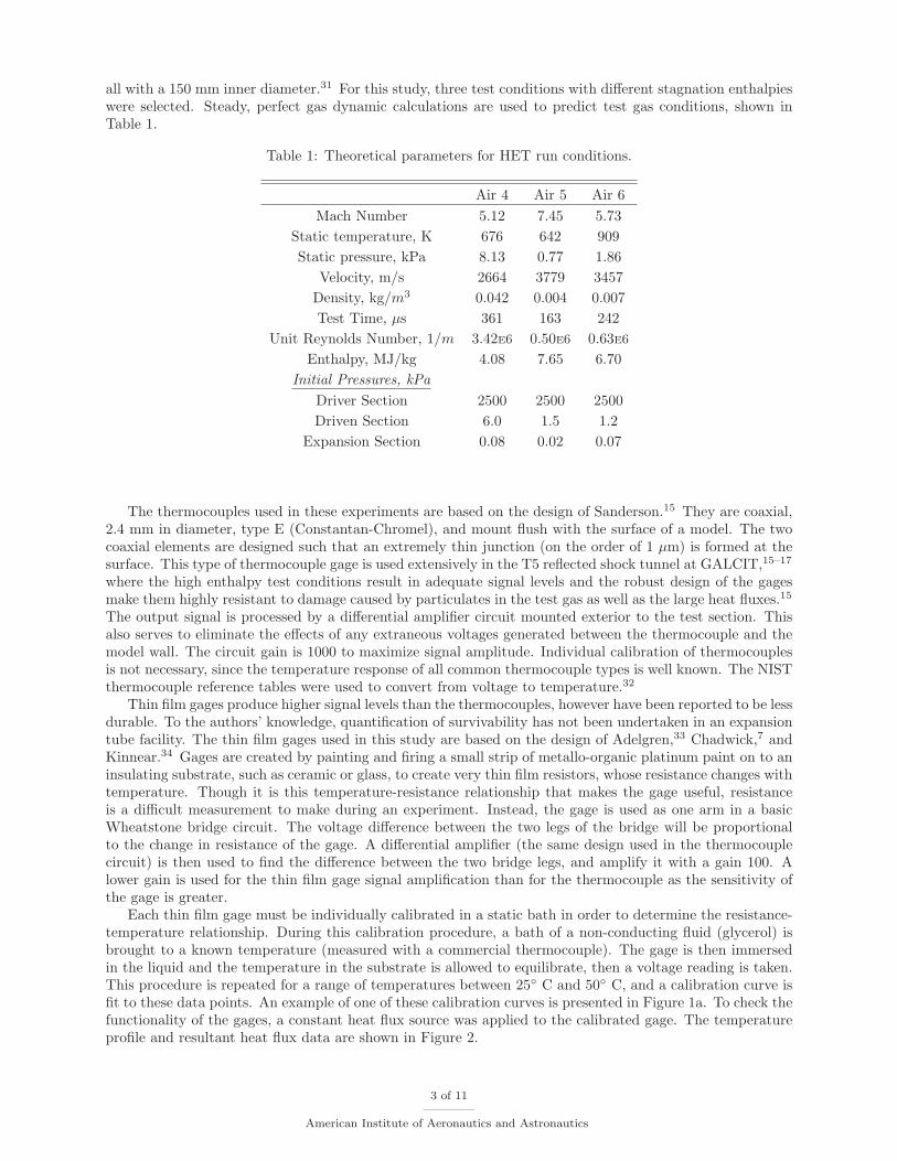
all with a 150 mm inner diameter.31 For this study, three test conditions with different stagnation enthalpieswere selected. Steady, perfect gas dynamic calculations are used to predict test gas conditions, shown inTable 1.
Table 1: Theoretical parameters for HET run conditions.
Air 4 Air 5 Air 6Mach Number 5.12 7.45 5.73
Static temperature, K 676 642 909Static pressure, kPa 8.13 0.77 1.86
Velocity, m/s 2664 3779 3457Density, kg/m3 0.042 0.004 0.007Test Time, μs 361 163 242
Unit Reynolds Number, 1/m 3.42E6 0.50E6 0.63E6
Enthalpy, MJ/kg 4.08 7.65 6.70Initial Pressures, kPa
Driver Section 2500 2500 2500Driven Section 6.0 1.5 1.2
Expansion Section 0.08 0.02 0.07
The thermocouples used in these experiments are based on the design of Sanderson.15 They are coaxial,2.4 mm in diameter, type E (Constantan-Chromel), and mount flush with the surface of a model. The twocoaxial elements are designed such that an extremely thin junction (on the order of 1 μm) is formed at thesurface. This type of thermocouple gage is used extensively in the T5 reflected shock tunnel at GALCIT,15–17
where the high enthalpy test conditions result in adequate signal levels and the robust design of the gagesmake them highly resistant to damage caused by particulates in the test gas as well as the large heat fluxes.15
The output signal is processed by a differential amplifier circuit mounted exterior to the test section. Thisalso serves to eliminate the effects of any extraneous voltages generated between the thermocouple and themodel wall. The circuit gain is 1000 to maximize signal amplitude. Individual calibration of thermocouplesis not necessary, since the temperature response of all common thermocouple types is well known. The NISTthermocouple reference tables were used to convert from voltage to temperature.32
Thin film gages produce higher signal levels than the thermocouples, however have been reported to be lessdurable. To the authors’ knowledge, quantification of survivability has not been undertaken in an expansiontube facility. The thin film gages used in this study are based on the design of Adelgren,33 Chadwick,7 andKinnear.34 Gages are created by painting and firing a small strip of metallo-organic platinum paint on to aninsulating substrate, such as ceramic or glass, to create very thin film resistors, whose resistance changes withtemperature. Though it is this temperature-resistance relationship that makes the gage useful, resistanceis a difficult measurement to make during an experiment. Instead, the gage is used as one arm in a basicWheatstone bridge circuit. The voltage difference between the two legs of the bridge will be proportionalto the change in resistance of the gage. A differential amplifier (the same design used in the thermocouplecircuit) is then used to find the difference between the two bridge legs, and amplify it with a gain 100. Alower gain is used for the thin film gage signal amplification than for the thermocouple as the sensitivity ofthe gage is greater.
Each thin film gage must be individually calibrated in a static bath in order to determine the resistance-temperature relationship. During this calibration procedure, a bath of a non-conducting fluid (glycerol) isbrought to a known temperature (measured with a commercial thermocouple). The gage is then immersedin the liquid and the temperature in the substrate is allowed to equilibrate, then a voltage reading is taken.This procedure is repeated for a range of temperatures between 25◦ C and 50◦ C, and a calibration curve isfit to these data points. An example of one of these calibration curves is presented in Figure 1a. To check thefunctionality of the gages, a constant heat flux source was applied to the calibrated gage. The temperatureprofile and resultant heat flux data are shown in Figure 2.
3 of 11
American Institute of Aeronautics and Astronautics

After initial experiments with an isolated gage, several thin film gages were painted onto a stagnationsphere model. Also, a special insert was made which could be mounted in a flat plate. This insert was 3inches long and 0.5 inches wide, and was designed to have 12 thin film gages on the surface. Channels werecut in the side of the insert so that wires could be attached to each gage without affecting the surface of themodel. The models were entirely immersed in the thermal bath for gage calibration. A calibration curve fora stagnation sphere gage is shown in Figure 1b.
(a) Calibration of an isolated thin film gage element. (b) Calibration of a model-mounted thin film gage.
Figure 1: Thin film calibration curves.
(a) Temperature history. (b) Surface heat transfer.
Figure 2: Thin film gage data obtained from an isolated gage element exposed to a constant heat flux.
A. Heat flux deconvolution
Two methods were investigated to deconvolve the heat flux from the gages, both of which assumed thatthe gage or substrate can be modeled as semi-infinite body during the test time. The first method usesLaplace transforms to solve the heat equation, and this solution is shown in Equation 1.35 In order to solvethis problem numerically, it is useful to use the discretized form, seen in Equation 2 (where the signal consistsof n + 1 measurements).
q̇(t) =
√ρck
π
t∫0
dT (τ)dτ
dτ√t − τ
(1)
q̇n =
√ρck
π
n∑i=1
Ti − Ti−1√tn − ti +
√tn − ti−1
(2)
where q̇(t) is the heat flux as a function of time, ρ, c, k are density, specific heat and thermal conductivityof the material respectively, and T is the temperature. The second method was introduced by Sanderson.15
The solution to the diffusion equation in a semi-infinite plate exposed to a surface heat flux is represented
4 of 11
American Institute of Aeronautics and Astronautics

by a convolution integral
ΔT (x, t) =
t∫0
g(x, t − τ)q̇(τ)dτ (3)
where ΔT is the change in temperature and g(x, t) is the impulse function, given by
g(x, t) =∂ΔT (x, t)
∂t=
√α
πk2texp
−x2
4αt(4)
where α is the thermal diffusivity and x is the junction depth. By taking the Fourier transform of theequation, it is possible to solve for the heat flux, such that
q̇n = FFT−1
[Sn
Gn
](5)
where Sn and Gn are the Fourier transforms of the temperature signal and the impulse function respectively.While the signal is in the frequency domain, a low-pass, 4th order filter is applied to it. The cut-off is set to 20kHz, as previous reports have shown that the gages carry little to no signal above this frequency range.15–17
Comparison of the heat flux calculated using both these methods showed that the spectral deconvolutionmethod resulted in a less noisy signal, in agreement with the results of Sanderson.15 It should be notedthat Sanderson’s method of spectral deconvolution is specific to the thermocouples of his design. Thus, Thenumerical integration method was used with the thin film gages, and spectral deconvolution was used withthe thermocouples.
B. Comparison with theoretical prediction
In order to compare both gage types, it was necessary to expose them to a known heat flux while operatingin the HET facility. Two model geometries were selected: a sphere and a flat plate. A self-similar solutionwas derived for heat transfer through a hypersonic boundary layer at the stagnation point of a sphere byFay and Riddell.36 A parametric study over a range of altitudes and velocities was carried out and anempirical curve to the data was obtained.36 Two reduced expressions have been derived to simplify heat fluxpredictions. The first was derived by Sutton and Graves,37 and is shown in Equation 6.
q̇ = K
√ps
R(h0,e − hw) (6)
where ps is the stagnation pressure, R is the sphere radius, h0,e is the test gas stagnation enthalpy, hw is thewall enthalpy, and K is a constant based on the gas composition. Another reduced expression was reportedby Filippis,38 Equation 7.
q̇ = 90√
ps
R(h0,e − hw)1.17 (7)
The equation derived by Filippis is valid solely for air, while the Sutton and Graves equation can be appliedto any gas mixture, as long as the value of K is known. The Filippis equation was derived to extend thepredictive range of the theory from a maximum flow enthalpy of 23 MJ/kg to 39 MJ/kg.38 Though theexperiments done here are within the 23 MJ/kg limit, the two equations still yield different results, and thusthe experimental measurements were compared against both theoretical predictions.
Theoretical predictions for laminar flat plate heat transfer were calculated with the reference enthalpymethod of Simeonides,39 and predictions of turbulent flat plate heat transfer were made using the Van DriestII method.40
III. Error Analysis
In order to make comparative measurements between the two gages it was necessary to evaluate theerror bars for each gage type. Davis16 calculated the sources of uncertainty for the thermocouple gagesdesigned by Sanderson. Two main sources of uncertainty were identified. First, there is error in the voltage-to-temperature conversion due to uncertainty in the NIST temperature conversion tables. Davis reports this
5 of 11
American Institute of Aeronautics and Astronautics

to be 1.7% in the temperature change, which corresponds directly to a 1.7% error in the heat flux. Secondly,there is uncertainty in the thermal properties of the thermocouple materials. Davis was able to determinethat the uncertainty of the thermal properties (as applied to the calculation of heat flux) was 8%. Thesevalues were used directly in this work since both the design and material choice were the same as used byDavis.
For the thin film gages the physical sources of uncertainty are the same as the same equation is solvedwhen deconvolving the heat flux, but the magnitudes of the uncertainty are different. In order to determinethe error in the voltage-to-temperature conversion it was necessary to evaluate the goodness of the calibra-tion fit. It was decided to use a full scale error approach in the same way Davis calculated the thermocoupleerror. Since the calibration was done over a 50 degree range, the full scale was chosen to be 50 degrees. Eachthin film gage was calibrated individually. Next, the average difference between the measured calibrationpoint and the calibration curve was used as the error in the temperature measurement. This error wasdifferent for each calibrated gage, and was again assumed to carry through directly to the heat flux. Theerror in the thermal property was taken from Miller.9 Though his method is different than that used here,Miller cites an unpublished Calspan report which uses the same gage construction method used here, andfound an uncertainty of 5% in the thermal properties.
It is important to note that this error analysis takes into account the physical uncertainties associatedwith the gage alone. There is also shot-to-shot variability in the test conditions. Small variations in initialtube fill pressures can cause fluctuations in the free stream properties,41 and therefore in the heat transfer.In addition, the free stream conditions have some unsteadiness during the test time. Heat transfer resultspresented here are averaged over the test time, which was experimentally measured using pitot probes.
IV. Results
A. Stagnation point results
To obtain directly comparable experimental results for both gages, two spherical models were designed. Athermocouple is mounted at the stagnation point of a 25.4 mm diameter stainless steel sphere, Figure 3a;this model can be seen sting-mounted in the test section of the HET in Figure 3b. For the thin film gages, ahemispherical blunt-body model with 25.4 mm nose diameter was created from the gage substrate material(in this case machinable ceramic MACOR R©), then sleeve-mounted to the sting. Three gages were painted inthe stagnation region, one at the stagnation point and two slightly offset. The MACOR thin film substratemodel is shown in Figure 3c.
Thermocouple data were taken at three different test conditions with calculated stagnation enthalpies
(a) Thermocouple mounted at thestagnation region of a 25.4 mm diam-eter sphere model.
(b) Thermocouple stagnation spheremounted in HET test section.
(c) Three thin film gages painted onthe stagnation region of a 25.4 mm di-ameter MACOR substrate model.
Figure 3: Thermocouple and thin film heat transfer gages mounted on spherical models.
from 4.09 to 7.52 MJ/kg (listed in Table 1). Figure 4 shows the comparison between the temperaturerise and the pitot pressure trace over a time period which encompasses the test gas. In all three plots,the temperature trace shows the arrival of the initial shock, accelerator gas, and contact surface, and theresponse time compares very well with the pitot pressure histories. The response time of the thermocouplegage was found to be sensitive to the degree of sanding used to create the thin thermocouple junction. Theexperimentally measured heat fluxes for each condition, and the theoretical predictions are listed in Table 2.
6 of 11
American Institute of Aeronautics and Astronautics
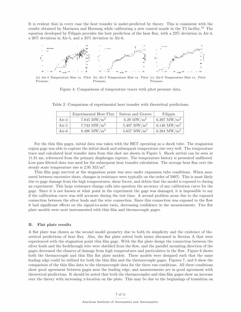
It is evident that in every case the heat transfer is under-predicted by theory. This is consistent with theresults obtained by Marineau and Hornung while calibrating a new conical nozzle in the T5 facility.42 Theequation developed by Filippis provides the best prediction of the heat flux, with a 23% deviation in Air-4,a 26% deviation in Air-5, and a 35% deviation in Air-6.
(a) Air-4 Temperature Rise vs. PitotPressure.
(b) Air-5 Temperature Rise vs. PitotPressure.
(c) Air-6 Temperature Rise vs. PitotPressure.
Figure 4: Comparisons of temperature traces with pitot pressure data.
Table 2: Comparison of experimental heat transfer with theoretical predictions.
Experimental Heat Flux Sutton and Graves FilippisAir-4 7.845 MW/m2 6.29 MW/m2 6.397 MW/m2
Air-5 7.743 MW/m2 5.407 MW/m2 6.146 MW/m2
Air-6 8.498 MW/m2 5.657 MW/m2 6.284 MW/m2
For the thin film gages, initial data was taken with the HET operating as a shock tube. The stagnationregion gage was able to capture the initial shock and subsequent temperature rise very well. The temperaturetrace and calculated heat transfer data from this shot are shown in Figure 5. Shock arrival can be seen at11.31 ms, referenced from the primary diaphragm rupture. The temperature history is presented unfiltered.Low-pass filtered data was used for the subsequent heat transfer calculation. The average heat flux over thesteady state temperature rise is 2.95 MJ/m2.
Thin film gage survival at the stagnation point was zero under expansion tube conditions. When mea-sured between successive shots, changes in resistance were typically on the order of 500%. This is most likelydue to gage damage from the high temperatures, shear forces, and debris that the model is exposed to duringan experiment. This large resistance change calls into question the accuracy of any calibration curve for thegage. Since it is not known at what point in the experiment the gage was damaged, it is impossible to sayif the calibration curve was still accurate during the test time. A second problem arose due to the exposedconnection between the silver leads and the wire connection. Since this connection was exposed to the flowit had significant effects on the signal-to-noise ratio, decreasing confidence in the measurements. Two flatplate models were next instrumented with thin film and thermocouple gages.
B. Flat plate results
A flat plate was chosen as the second model geometry due to both its simplicity and the existence of the-oretical predictions of heat flux. Also, the flat plate solved both issues discussed in Section A that wereexperienced with the stagnation point thin film gage. With the flat plate design the connection between thesilver leads and the feedthrough wire were shielded from the flow, and the parallel mounting direction of thegages decreased the chances of damage from high temperatures and particulates in the flow. Figure 6 showsboth the thermocouple and thin film flat plate models. These models were designed such that the sameleading edge could be utilized for both the thin film and the thermocouple gages. Figures 7, and 8 show thecomparison of the thin film data to the thermocouple data for the three run conditions. All three conditionsshow good agreement between gages near the leading edge, and measurements are in good agreement withtheoretical predictions. It should be noted that both the thermocouples and thin film gages show an increaseover the theory with increasing x-location on the plate. This may be due to the beginnings of transition on
7 of 11
American Institute of Aeronautics and Astronautics

(a) Raw temperature history. (b) Surface heat transfer.
Figure 5: Initial thin film data obtained in the HET after shock wave passage.
the plate. Transition was not anticipated at the lower Reynolds numbers of Air 5 and Air 6, and furtherexperiments are required to address this issue.
(a) Thermocouple flat plate model. (b) Thin film flat plate model.
Figure 6: Flat plate models.
V. Conclusions
Thermocouples and thin film gages are used extensively for surface heat transfer measurements in hyper-sonic impulse facilities. Coaxial thermocouples are robust, can survive challenging experimental conditions,and are typically used in higher enthalpy flows. Thin film resistance gages provide improved signal levels,but have to be individually calibrated and are less robust, and are typically used in lower enthalpy flows.The goal of this work is to make directly comparative measurements in flow fields accessible to both gagetypes with stagnation enthalpies between 4.09 and 7.52 MJ/kg.
We report on the design and construction of both coaxial thermocouples and thin film resistance ther-mometers. Gages are mounted on equivalent spherical and flat plate models. Thermocouple gages areinternally mounted, while thin film gages are directly painted and fired onto a MACOR model which acts asthe gage substrate, and calibrated in situ.
Both gages have been successfully used in the HET. Tests demonstrate that thermocouple gages arepreferable for use in stagnation regions due to the extremely poor survivability of thin film gages. Bothgages show good agreement in the flat plate case, though thin film gages have less noise, a higher signallevel, and more consistent response time. Thus, in mounting locations where survivability is not an issue,
8 of 11
American Institute of Aeronautics and Astronautics

Figure 7: Comparison of thin film (×) and thermocouple (•) heat flux data in Air-4 (leading edge at x=0).
Figure 8: Comparison of thin film (×) and thermocouple (•) heat flux data in Air-6 (leading edge at x=0).
thin film gages are the preferred gage type.
Acknowledgments
This work was funded through the Air Force Office of Scientific Research FA9550-08-1-0172 with Dr.John Schmisseur as program manager. We are grateful to the Caltech T5 group, Prof. Hans Hornung,Bahram Valiferdowski, Drs Eric Marineau, Adam Rasheed, and Ivett Leyva for their valuable help withthermocouples and to Lt. Col. Prof. Russell Adelgren for useful discussions on thin film gages. The authorswould like to thank Ryan Fontaine, Manu Sharma, and Andy Swantek for their help with this work.
References
1Holden, M. S., Wadhams, T. P., Smolinski, G. J., Maclean, M. G., Harvey, J., and Walker, B. J., “Experimental andNumerical Studies on Hypersonic Vehicle Performance in the LENS Shock and Expansion Tunnels,” 44th AIAA AerospaceScience Meeting and Exhibit , January 2006.
9 of 11
American Institute of Aeronautics and Astronautics

2Holden, M. S., Wadhams, T. P., Maclean, M. G., Mundy, E., and Parker, R. A., “Experimental Studies in LENS I andX to Evaluate Real Gas Effects on Hypervelocity Vehicle Performace,” 45th AIAA Aerospace Science Meeting and Exhibit,January 2007.
3Holden, M. S., Wadhams, T. P., Maclean, M., Mundy, E., and Parker, R. A., “Experimental Studies in LENS I andX to Evaluate Real Gas Effects on Hypervelocity Vehicle Performance,” 45th AIAA Aerospace Sciences Meeting and Exhibit,January 2007.
4Maclean, M. and Holden, M. S., “Catalytic Effects on Heat Transfer Measurements for Aerothermal Studies with CO2,”44th AIAA Aerospace Sciences Meeting and Exhibit, January 2006.
5Wadhams, T., Mundy, E., Maclean, M., and Holden, M., “Experimental and Analytical Study of Transition in HighSpeed Flows at CUBRC,” 38th Fluid Dynamics Conference and Exhibit , June 2008.
6MacLean, M., Holden, M., and Hollis, B., “Investigation of Blunt Bodies with CO2 Test Gas Including Cataltytic Effects,”38th AIAA Thermophysics Conference, June 2005.
7Chadwick, K. M., “Stagnation heat transfer measurement techniques in hypersonic shock tunnel flows over sphericalsegments,” 32nd AIAA Thermophysics Conference, June 1997.
8Wadhams, T. P., Maclean, M., Holden, M. S., and Smolinski, G. J., “Return to Flight Testing of a 3.5Model at MachNumbers of 3.5 and 4.0,” 44th AIAA Aerospace Sciences Meeting and Exhibit, January 2006.
9Miller, C. G., “Comparison of Thin-Film Resistance Heat -Transfer Gages With Thin-Skin Transient Calorimeter Gagesin Conventional Hypersonic Wind Tunnels,” NASA Technical Memorandum 83197, NASA, 1981.
10Kidd, C. T., “Coaxial Surface Thermocouples: Analytical and Experimental Considerations for Aerothermal Heat-FluxMeasurement Applications,” Proceedings of the ISA Aerospace Instrumentation Symposium, 1990.
11Kidd, C. T., Nelson, C. G., and Scott, W. T., “Extreaneous Thermoelectrioc EMF Effects Resulting from Press-FitInstallation of Coaxial Thermocouples in Metal Models,” Proceedings of the ISA Aerospace Instrumentation Symposium, 1994.
12Hollis, B. R., Berger, K. T., Horvath, T. J., Coblish, J. J., and Norris, J. D., “Aeroheating Testing and Predictions forProject Orion CEV at Turbulent Conditions,” 46th AIAA Aerospace Sciences Meeting and Exhibit, January 2008.
13Reddy, N. M., “Heat-Rate Measurements Over 30 and 40 (Half-Angle) Blunt Cones in Air and Helium in the LangleyExpansion Tube Facility,” NASA Technical Memorandum 80207, NASA, 1980.
14Hollis, B. R., Liechty, D. S., Wright, M. J., Holden, M. S., Wadhams, T. P., Maclean, M., and Dyakonov, A., “TransitionOnset and Turbulent Heating Measurements for the Mars Science Laboratory Entry Vehicle,” 43th AIAA Aerospace SciencesMeeting and Exhibit , January 2005.
15Sanderson, S. R., Shock wave interaction in hypervelocity flow , Ph.D. thesis, California Institute of Technology, Pasadena,California, 1995.
16Davis, J.-P., High-Enthalpy Shock/Boundary-Layer Interaction on a Double Wedge, Ph.D. thesis, California Institute ofTechnology, Pasadena, California, 1999.
17Rasheed, A., Passive Hypervelocity Boundary Layer Control Using an Ultrasonically Absorptive Surface, Ph.D. thesis,California Institute of Technology, Pasadena, California, 2001.
18Leyva, I. A., Shock detachment process on cones in hypervelocity flows., Ph.D. thesis, California Institute of Technology,Pasadena, California, 1999.
19Mee, D. J., “Boundary-Layer Transition Measurements in Hypervelocity Flows in a Shock Tunnel,” AIAA Journal ,Vol. 40, No. 8, Aug 2002, pp. 1542–1548.
20Capra, B. R., Levland, P., and Morgan, R. G., “Subscale Testing of the Fire II Vehicle in a Superorbital ExpansionTube,” 42th AIAA Aerospace Science Meeting and Exhibit, January 2004.
21Wright, M. J., Olejniczak, J., Brown, J. L., Hornung, H. G., and Edquist, K. T., “Modeling of Shock Tunnel AeroheatingData on the Mars Science Laboratory Aeroshell,” Journal of Thermophysics and Heat Transfer , Vol. 20, No. 4, 2006, pp. 641–651.
22Marineau, E. and Hornung, H., “Modeling and Calibration of Fast-Response Coaxial Heat Flux Gages,” 47th AIAAAerospace Sciences Meeting, Jan 2009.
23Salvadaor, I. I., Minucci, M. A. S., Toro, P. G. P., Oliveira, A. C., and Jr, J. B. C., “Development of Surface Junc-tion Thermocouples for High Enthalpy Measurements,” American Institute of Physics Beamed Energy Propulsion: FourthInternational Symposium, 2006.
24Kuchi-ishi, S., Watanabe, S., Nakakita, K., Koyama, T., Ueda, S., and Katsuhiro, “Comparative Heat Flux MeasurmentsBetween Three Hypersonic Test Facilities at NAL,” 33rd AIAA Fluid Dynamics Conference and Exhibit , June 2003.
25Hornung, H. G., “Performance data of the new free-piston shock tunnel at GALCIT,” 17th AIAA Aerospace GroundTesting Conference, July 1992.
26Hannemann, K. and Beck, W. H., Advanced Hypersonic Test Facilities, chap. Aerothermodynamics Research in the DLRHigh Enthalpy Shock Tunnel HEG, AIAA, Reston, VA, 2002, pp. 205–238.
27Holden, M. S. and Parker, R. A., Advanced Hypersonic Test Facilities, chap. LENS Hypervelocity Tunnels and Applicationto Vehicle Testing at Duplicated Flight Conditions, AIAA, Reston, VA, 2002, pp. 73–110.
28Micol, J. R., “Langley Aerothermodynamic Facilities Complex: Enhancements and Testing Capabilities,” AIAA Paper ,1997.
29Morgan, R. G., “Development of X3, a superorbital expansion tube,” 38th AIAA Aerospace Sciences Meeting and Exhibit,January 2000.
30Sasoh, A., Ohnishi, Y., Koremoto, K., and Takayama, K., “Operation Design and Performance of a Free-Piston-DrivenExpansion Tube,” 37th AIAA Aerospace Sciences Meeting and Exhibit, January 1999.
31Dufrene, A., Sharma, M., and Austin, J. M., “Design and Charachterization of a Hypervelocity Expansion Tube Facility,”Journal of Propulsion and Power , Vol. 23, No. 6, Nov 2007, pp. 1185–1193.
10 of 11
American Institute of Aeronautics and Astronautics

32Croarkin, M. C., Guthrie, W. F., Burns, G. E., Kaeser, M., and Strouse, G. F., “Temperature-Electromotive ForceReferance Function and Tables for the Letter-Designated Thermocouple Types Based on the ITS-90.” Monograph 175, NationalInstitute of Standard Technologies, 1993.
33Adelgren, R. G., Localized Flow Control with Energy Deposition, Ph.D. thesis, Rutgers University, New Brunswick, NJ,2002.
34Kinnear, K. M. and Lu, F. K., “Design, Calibration and Testing and Transient Thin Film Heat Transfer Gauges,” AIAAPaper , 1998.
35Schultz, D. L. and Jones, T. V., “Heat-transfer Measurements in Short-duration Hypersonic Facilities,” Agardograph165, AGARD, 1973.
36Fay, J. A. and Riddell, F. R., “Theory of Stagnation Point Heat Transfer in Dissociated Air,” Journal of the AeronauticalSciences, Vol. 25, No. 2, 1958, pp. 73–85.
37Sutton, K. and Graves, A. R., “A general stagnation-point convective-heating equation for arbitary gas mixtures,” Tech.rep., NASA, 1971.
38Filippis, F. D. and Serpico, M., “Air High-Enthalpy Stagnation Point Heat Flux Calculation,” Journal of Thermophysics,Vol. 12, No. 4, 1998, pp. 608–610.
39Simeonides, G., “Gerneralized reference enthalpy formulations and simulation of viscous effects in hypersonic flows,”Shock Waves, Vol. 8, 1998, pp. 161–172.
40Driest, E. V., “Turbulent Boundary Layers in Compressible Fluids,” Journal of the Aeronautical Sciences, Vol. 18, 1951,pp. 145–160.
41McGilvray, M., Austin, J., Sharma, M., Jacobs, P., and Morgan, R., “Diagnostic Modelling of an Expansion TubeOperating Condition,” Shock Waves, Vol. 19, No. 1, 2009, pp. 59–66.
42Marineau, E. and Hornung, H., “Heat Flux Calibration of T5 Hypervelocity Shock Tunnel Conical Nozzle in Air,” 47thAIAA Aerospace Sciences Meeting, Jan 2009.
11 of 11
American Institute of Aeronautics and Astronautics