comparison of air kerma-length product measurements
TRANSCRIPT

Metrologia 52 (2015) Tech. Suppl. 06014
Page 1/13
Comparison of air kerma-length product measurements between the PTB and
the IAEA for x-radiation qualities used in computed tomography
(EURAMET.RI(I)-S12, EURAMET project #1327)
István Csete1, Ludwig Büermann
2, Babak Alikhani
2 and Igor Gomola
1
1 International Atomic Energy Agency (IAEA), Vienna, Austria 2 Physikalisch-Technische Bundesanstalt (PTB), Bundesallee 100, 38116 Braunschweig, Germany
E-mail: [email protected]
Abstract
A comparison of air kerma-length product determinations for standard radiation qualities defined for
use in computed tomography (CT) was performed between the PTB and the IAEA as EURAMET
project #1327, registered in the KCDB as the EURAMET.RI(I)-S12 comparison. A pencil type
reference-class ionization chamber of the IAEA and the three RQT beam qualities established
according to the IEC standard 61627:2005 were selected for the comparison. The calibration
coefficients for the transfer chamber in terms of Gycm/C at the PTB and the IAEA using the partial
irradiation method recommended in the IAEA TRS 457 were determined. The results show the
calibration coefficients of both laboratories were in a very good agreement of about 0.2 % well
within the estimated relative standard uncertainty of the comparison of about 0.8 %. Residual
correction due to the additional aperture required for partial irradiation of pencil chambers and
feasibility of the full irradiation method were also studied.
1. Introduction
The IAEA Dosimetry Laboratory in Seibersdorf Austria, performs calibration of reference
diagnostic dosemeters of IAEA/WHO SSDL1 Network members (more than 80 laboratories
worldwide). As a signatory of the CIPM MRA, the IAEA maintains a quality management
system (QMS) being in compliance with ISO 17025. The IAEA published its revised
dosimetry CMC claims in 2013, in the Appendix C database of the CIPM MRA. For
extension of these CMC claims with calibration of CT pencil chambers in terms of air
kerma-length, a “supporting evidence” for the measuring capability, in addition to the
traceability of the measured quantity, is required. A published comparison report is the
most straightforward supporting evidence. There are few publications dealing with the CT
chamber calibrations [1, 2], however this is the first publication of a comparison performed
in terms of air kerma-length product although three NMIs have already published their
CMCs for CT chamber calibration.
The recommended calibration method for CT pencil-type chambers in the IAEA Diagnostic
Code of Practice TRS 457 [1] is the partial irradiation method using an additional aperture
to limit the beam length between 20 and 50 mm. The calibration procedure adopted for CT
chambers at the IAEA defining the irradiation length by an aperture of 5×5 cm2 positioned
5 cm in front of the chamber. In case of determination of the air kerma length calibration
coefficient based on the measured air kerma rate without aperture, in-scattered radiations
from the edges of the inserted aperture were taken into account. This unwanted residual
signal depends on the non-limiting (perpendicular to the chamber axis) aperture size, shape
of the aperture edges, and its distance from the chamber. The associated correction factor,
kresidual, can be determined by extrapolation of the measured signal against the irradiated
length, normalised to the length used for the calibration [2, 3].
The IAEA secondary standard ionization chamber type Exradin A3 used for reference air
kerma determination is traceable to the air kerma standards of the PTB. The PTB maintains
primary standards of air kerma for a wide variety of radiation qualities used in radiation
therapy, diagnostic radiology and mammography. The PTB has published degrees of
equivalence (DoE) in the key comparison database (KCDB) of the CIPM MRA based on
the results in the key comparisons BIPM.RI(I)-K2 (low-energy X rays), K3 (medium-
Metrologia 52 (2015) Tech. Suppl. 06014
Page 2/13
energy X rays) and K7 (mammography X rays) [7,8,9]. For the diagnostic X ray beam
qualities specified in the IEC 61267 [4] one supplementary comparison Euramet.RI(I)-S10
has been published [6]. The current bilateral comparison is registered as EURAMET
project #1327 and EURAMET.RI(I)-S12 comparison in the KCDB.
2. Comparison procedure
2.1 The transfer instrument
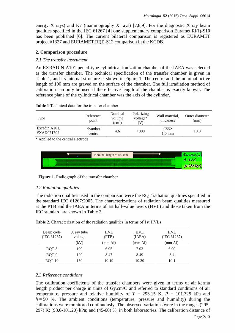
An EXRADIN A101 pencil-type cylindrical ionization chamber of the IAEA was selected
as the transfer chamber. The technical specification of the transfer chamber is given in
Table 1, and its internal structure is shown in Figure 1. The centre and the nominal active
length of 100 mm are graved on the surface of the chamber. The full irradiation method of
calibration can only be used if the effective length of the chamber is exactly known. The
reference plane of the cylindrical chamber was the axis of the cylinder.
Table 1 Technical data for the transfer chamber
Type Reference
point
Nominal
volume
(cm3)
Polarizing
voltage*
(V)
Wall material,
thickness
Outer diameter
(mm)
Exradin A101,
#XAD071702 chamber
centre 4.6 +300
C552
1.0 mm 10.0
* Applied to the central electrode
Figure 1. Radiograph of the transfer chamber
2.2 Radiation qualities
The radiation qualities used in the comparison were the RQT radiation qualities specified in
the standard IEC 61267:2005. The characterizations of radiation beam qualities measured
at the PTB and the IAEA in terms of 1st half-value layers (HVL) and those taken from the
IEC standard are shown in Table 2.
Table 2. Characterization of the radiation qualities in terms of 1st HVLs
Beam code
(IEC 61267)
X ray tube
voltage
HVL
(PTB)
HVL
(IAEA)
HVL
(IEC 61267)
(kV) (mm Al) (mm Al) (mm Al)
RQT-8 100 6.95 7.03 6.90
RQT-9 120 8.47 8.49 8.4
RQT-10 150 10.19 10.20 10.1
2.3 Reference conditions
The calibration coefficients of the transfer chambers were given in terms of air kerma
length product per charge in units of Gy.cm/C and referred to standard conditions of air
temperature, pressure and relative humidity of T = 293.15 K, P = 101.325 kPa and
h = 50 %. The ambient conditions (temperature, pressure and humidity) during the
calibrations were monitored continuously. The observed variations were in the ranges (295-
297) K; (98.0-101.20) kPa; and (45-60) %, in both laboratories. The calibration distance of
Nominal length = 100 mm

Metrologia 52 (2015) Tech. Suppl. 06014
Page 3/13
100 cm, from the focus of X-ray tubes to the reference plane was applied at both
laboratories.
3 Calibration at the PTB
3.1 The PTB irradiation facility and equipment
The IEC 61267 RQT radiation qualities used in this comparison are produced with a
unipolar X ray tube of type Comet MXR 165 with a W anode angle of 30° combined with a
constant potential generator. The inherent filtration is 4 mm Beryllium. The diameter of the
circular beam at 1 m distance from the focus was 10 cm. The air kerma rates were around
60 mGy/min.
The high voltage was measured invasively with a voltage divider manufactured and
calibrated at PTB. Photon fluence spectra of all radiation qualities were measured with a
high-purity germanium detector. Characteristic radiation quality data such as mean energies
and half-value layers are evaluated from these spectra. The first Al-half-value layers of the
qualities used in this comparison are listed in Table 2.
A transmission-type monitor chamber was used to normalize the X ray beam output. A
thermistor measures the temperature of the air inside the shielding box surrounding the
free-air chamber. Air pressure is measured by means of a calibrated barometer positioned
in the irradiation room. The PTB laboratory humidity is not controlled because it varies by
no more than between 30 % and 60 % and this is taken into account by an additional
uncertainty in the humidity correction factor. No humidity correction was applied to the
current measured using the transfer instrument. Each calibration is based on 5 repeated
measurements of the ionization charge measured in 60 s with the standard and the chamber
to be calibrated. The leakage is measured before and after the 5 repeated measurements and
the mean value is subtracted from the mean of the measured charge.
3.2 Determination of the air-kerma rate
The PTB maintains a cylindrical type “Fasskammer (FK)” primary standard free-air
chamber for radiation qualities produced with tube voltages between 30 kV and 300 kV.
For a free-air ionization chamber standard with measuring volume V, the air kerma rate is
determined by the relation
i
ikge
W
V
IK
air
air
air 1
1
(1)
where air is the density of air under reference conditions, I is the ionization current under
the same conditions, Wair is the mean energy expended by an electron of charge e to
produce an ion pair in air, gair is the fraction of the initial electron energy lost through
radiative processes in air, and ki are the correction factors to be applied to the standard.
Table 3. Physical constants used in the determination of the air-kerma rate
Constant Value uia
airb 1.2930 kg m
–3 0.0001
Wair / e 33.97 J C–1
0.0015
a ui is the relative standard uncertainty.
b Density of dry air at T0 = 273.15 K and P0 = 101.325 kPa.

Metrologia 52 (2015) Tech. Suppl. 06014
Page 4/13
The values used for the physical constants air and Wair /e are given in Table 3. For use with
this dry-air value for air, the ionization current I must be corrected for humidity and for the
difference between the density of the air of the measuring volume at the time of
measurement and the value given in the table.
The PTB cylindrical free-air chamber FK is in use as a primary air-kerma standard for X
radiations produced with tube voltages between 30 kV and 300 kV. A set of five central
collecting electrodes, each 7 mm in diameter and with lengths between 5 cm and 25 cm,
can be used in combination with a set of five diaphragms with diameters between 0.8 cm
and 3.0 cm, yielding a measuring volume between 2.5 cm3 and 180 cm
3. The main
dimensions and technical data for the chamber in the configuration used for the comparison
are given in Table 4. A particularity of the cylindrical geometry is that the X ray beam
enters the chamber 45 mm off-axis, parallel to the central electrode. This necessitates the
use of a correction factor, ksh, not relevant for parallel-plate chambers, that corrects for the
shadowing of the collector due to absorption of some secondary electrons resulting in
ionization loss.
Table 4. Main characteristics of the PTB medium-energy cylindrical free-air chamber
Aperture diaphragm diameter / cm 2.0009
Aperture diaphragm thickness / cm 1
Collecting (central) electrode length / cm 20.001
Outer electrode diameter / cm 20
Measuring volume / cm3 62.892
Polarising voltage / V +3000
Air attenuation path length / cm 48.1
Leakage current / fA <100
Table 5. Correction factors for the PTB Faßkammer standard
(a)
Generating potential / kV RQT 8 RQT9 RQT10 uiA uiB
Air attenuation ka(b)
1.0125 1.0115 1.01057 - 0.10
Ionization gain ksc(c)
0.9929 0.9935 0.9940 - 0.05
Electron loss ke 1.0000 1.0000 1.0001 - 0.05
Ion recombination ks 1.0039 1.0038 1.0037 0.05 -
Field distortion kd 1.0000 1.0000 1.0000 - 0.10
Polarity effect kpol 1.0000 1.0000 1.0000 0.05 -
Shadow effect, ksh 1.0017 1.0021 1.0021 - 0.05
Aperture edge trans. kl 1.0000 1.0000 1.0000 - 0.05
Wall transmission kp 1.0000 1.0000 1.0000 0.05 -
Humidity kh 0.9980 0.9980 0.9980 - 0.10
1 – gair 1.0000 1.0000 1.0000 - - (a)
Component uncertainties below 0.0002 have been neglected. (b)
Nominal values for 293.15 K and 1013.25 hPa; each measurement is corrected using the air density
measured at the time. (c)
This corrects for the re-absorption of scattered radiation and of fluorescence photons.
This and the other correction factors applied to the FK standard for the radiation qualities
used in this comparison are given in Table 5. The relative standard uncertainties associated
with the air kerma rate determination with the FK are summarized in Table 6 and result in a
combined standard uncertainty of 0.30 %. They were evaluated according to the GUM [5].

Metrologia 52 (2015) Tech. Suppl. 06014
Page 5/13
Table 6. Relative standard uncertainties (in %) associated with the standard “Faßkammer”
Source of uncertainty PTB
Type A Type B Ionization current 0.10 0.06
Volume 0.06
Positioning 0.01
Correction factors 0.09 0.20
Physical constants 0.15
FKK 0.13 0.26
0.30
3.3 Calibration of the air kerma-length product chamber at a nominal length of 5cm
The calibration of an air kerma-length product chamber is done in two steps:
1. The air kerma rate is measured at a distance of 1m from the source with the primary
standard free air chamber type "Fasskammer" according to chapter 2.2.
2. A rectangular aperture with an opening of width 50.11 mm and height 30.08 mm
was centred on the central axis of the beam at a distance of 98 cm from the focal
spot. The chamber was positioned horizontally perpendicular to the beam axis with
the centre of the marked ring on the middle of the chamber located on the beam axis
at 100 cm from the focal spot. The details are shown in Figure 2.
Figure 2. Setup for CT chamber calibrations at the PTB. (d1 = 978.8 mm, d2 = 1000 mm, d3 = 5mm,
w1 = 50.11 mm, w2 = 51.06 mm)
The conventional true value of the air kerma length product KLP is obtained from equation
(2).
residualnuFK kkLKPKL (2)
where FKK is the air kerma measured with the free-air chamber, L is the effective
irradiated length of the CT chamber, nuk corrects for influences of the non-uniformity of
the beam in horizontal direction along the axis of the CT chamber and residualk corrects for
the influences of photons transmitted through and scattered at the rectangular aperture
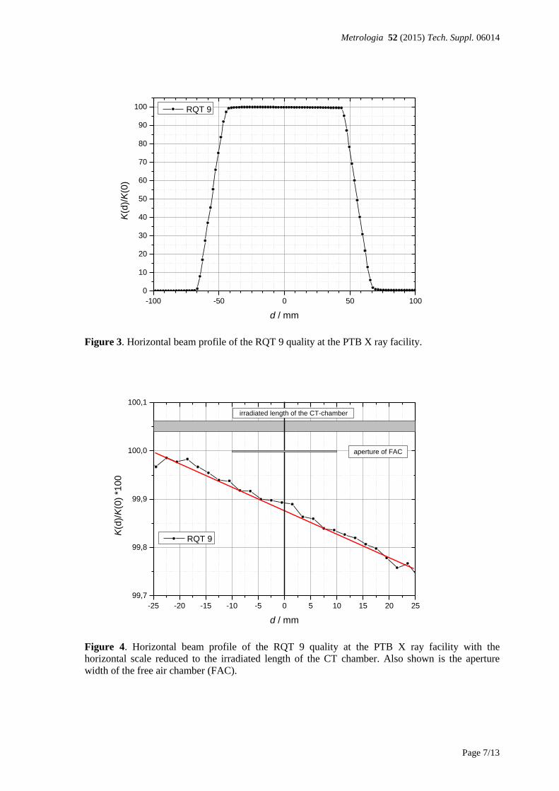
edges. The correction factor nuk was obtained from measurements of the horizontal beam
dose profile with a small farmer type ionisation chamber of type PTW TM30013-451
shown in Figure 3. The X ray tube of type Comet MXR 165 is used in a vertical position

Metrologia 52 (2015) Tech. Suppl. 06014
Page 6/13
which means that the cathode – anode axis is perpendicular to the horizontal alignment of
the CT chamber axis. Therefore the Heel effect is not present along the axis of the CT
chamber. In Figure 4 it is shown that the dose rate varies by less than 0.3 % along the
irradiated length of the CT chamber. As the dose rate varies approximately linear the
correction factor nuk was estimated to be close to 1 with a relative standard uncertainty of
0.1 %. The correction residualk was obtained from similar methods as described in chapter 4
of this report and found to be close to 1 with an estimated relative standard uncertainty of
0.1 %. The effective irradiated length of the CT chamber was estimated at 51.08 mm with a
standard uncertainty of 0.3 mm which is about 0.59 % and is the largest contribution to the
uncertainty. Using these values and the relative uncertainty of FKK shown in Table 6 the
relative standard uncertainty of KLP was estimated at 0.67 % as shown in Table 7. The
relative standard uncertainty associated with the calibration of the CT chamber was
estimated at 0.69 % as shown in Table 8 and 0.63 % if uncertainties due to physical
constants are omitted as shown in Table 9.
Table 7. Relative standard uncertainties (in %) associated with the determination of the air-kerma
length product PKL
Source of uncertainty PTB
Type A Type B Air kerma KFK 0.13 0.26
Irradiated length L 0.59
Correction factor knu 0.10
Correction factor kresidual 0.10
PKL 0.62 0.26
0.67
Table 8. Relative standard uncertainties (in %) associated with the calibration of the transfer
ionization chamber in terms of air kerma-length product
Source of uncertainty Type A Type B
Air-kerma length product KLP 0.62 0.26
Ionization current 0.10 0.06
Positioning 0.05
Monitor normalization 0.05
Air density correction 0.05
NKL,PTB 0.63 0.27
0.69
Table 9. Relative standard uncertainties (in %) associated with the calibration of the transfer
ionization chamber in terms of air kerma-length product if the uncertainties due to the physical
constants are omitted
Source of uncertainty Type A Type B
Air-kerma length product KLP 0.61 0.06
Ionization current 0.10 0.06
Positioning 0.05
Monitor normalization 0.05
Air density correction 0.05
NKL,PTB 0.62 0.10
0.63
Metrologia 52 (2015) Tech. Suppl. 06014
Page 7/13
Figure 3. Horizontal beam profile of the RQT 9 quality at the PTB X ray facility.
Figure 4. Horizontal beam profile of the RQT 9 quality at the PTB X ray facility with the
horizontal scale reduced to the irradiated length of the CT chamber. Also shown is the aperture
width of the free air chamber (FAC).
-100 -50 0 50 100
0
10
20
30
40
50
60
70
80
90
100
K(d
)/K
(0)
d / mm
RQT 9
-25 -20 -15 -10 -5 0 5 10 15 20 25
99,7
99,8
99,9
100,0
100,1
K(d
)/K
(0)
*10
0
d / mm
RQT 9
aperture of FAC
irradiated length of the CT-chamber

Metrologia 52 (2015) Tech. Suppl. 06014
Page 8/13
4 Calibration at the IAEA
4.1 The IAEA irradiation facility and equipment
An X ray tube type ISOVOLT MXR161/0.4-3.0 is used to generate the RQT diagnostic X
ray beam qualities at the IAEA. The output of the high-voltage generator, type ISOVOLT
160 Titan E, is monitored by a high-voltage divider, type FUG HVT 160 000, calibrated at
the PTB. Ionization currents are measured by Keithley K6517A electrometers normalized
to the monitor chamber manufactured by Titon Bt. Hungary. The internal capacitance and
all ranges of the electrometers are calibrated by a Keithley calibrator, type 263, traceable to
voltage and capacitor standards of the BEV. The reference air kerma rate for the calibration
of the transfer chamber was determined by the IAEA reference secondary standard
chamber, type Exradin A3, calibrated at the PTB in 2012.
The long-term stability of the Exradin A3 reference chamber is better than 0.25 % based on
the results of recalibrations at the PTB and back up chambers against the reference chamber
at the IAEA. For each beam quality, the air-kerma rate of 50 mGy/min was applied. No
further corrections for saturation, beam non-uniformity, and spectral differences were
applied for the determination of the reference air-kerma rates due to the similar calibration
conditions at both laboratories.
3.2 Setup for CT chamber calibration
The reference point of the transfer chamber was positioned in the reference plane at 100 cm.
The vertical size of the rectangular aperture is fixed 5 cm, meanwhile the horizontally can
be changed from zero to 110 mm. The sharp 85° angle edges of the aperture were precisely
manufactured to reduce the scattered photons and the uncertainty contribution from
determination of the irradiated length. The CT chamber behind the aperture can be moved
along its axis to irradiate any part of the active length. The X ray tube is installed in a
vertical position which means that the cathode to anode axis is perpendicular to the
horizontal alignment of the CT chamber axis to eliminate the heel effect of the X ray tube.
Details of the setup are shown in Figure 5.
Figure 5. Setup for CT chamber calibrations at the IAEA. (d1 = 950 mm, d2 = 1000 mm, d3 = 5mm,
w1 = 50 mm, w2 = 52.63 mm)
The uncertainties associated with the calibrations at the IAEA are listed in Table 9. The
various sources of uncertainty are grouped according to [5] as type A (statistical) and Type
B (non-statistical, based on scientific judgement) The uncertainty of the calibration
coefficient in terms of kerma-length product, NPk, is obtained essentially by combining the
uncertainty of the reference air kerma rate determined free in air and specific uncertainty
components related to the partial irradiation method of pencil chamber namely the
irradiation length and residual correction. Beam profiles measured in the reference plane at

Metrologia 52 (2015) Tech. Suppl. 06014
Page 9/13
the distance of 100 cm are shown in Figure 6. The beam profiles measured at both
laboratories ensured relatively uniform irradiation of the transfer chamber. Instead of the
application of a calculated radial non-uniformity correction factor, an additional uncertainty
component was introduced in both laboratories.
However, for this comparison the uncertainty components of the IAEA air kerma standard
due to the physical constants and correction factors of the PTB primary standard should be
removed because the IAEA secondary-standard chambers are traceable to the PTB primary
standards.
Table 10. Estimated combined standard uncertainty of a CT chamber calibration for RQT beam
qualities at the IAEA
Type A Type B
Uncertainty (%)
Step 1: Reference standard
*Calibration from BIPM/PSDL 0.29
Long term stability of the reference standard 0.25
Spectral difference of the beam at DOL and PSDL 0.06
Chamber positioning 0.03
Current measurements including range and time base corrections 0.02 0.05
Uncertainty due to temperature measurements 0.03
Uncertainty due to pressure measurements 0.01
Monitor chamber contribution 0.02
Relative combined standard uncertainty of Kair 0.03 0.39
Step 2: CT chamber to be calibrated
Uncertainty due to temperature measurements 0.01 0.03
Uncertainty due to pressure measurements 0.01 0.01
Monitor chamber contribution 0.02
Chamber positioning 0.03
**Difference in radial non-uniformity of the beam 0.20
Homogeneity of the active length 0.05
Projected irradiated length 0.16
Residual correction 0.10
Repeatability (new setup) 0.20
Relative combined standard uncertainty in Step 2 0.06 0.34
Relative combined standard uncertainty (Steps 1 + 2)
0.06
0.52
Overall relative uncertainty
0.53
* Reduced uncertainty of the PTB calibration of the IAEA secondary standard from uc = 0.4 % without uncertainties of physical constants and correction factors of PTB primary standard. [6]
** Different beam size used for reference air kerma determination and the pencil chamber calibration, see Figure 4.

Metrologia 52 (2015) Tech. Suppl. 06014
Page 10/13
Figure 6. X ray beam profiles measured at the IAEA diagnostic calibration facility.
5 Measurement results
The calibration coefficients were determined using the substitution method at both
laboratories, from a minimum of 3 repeated measurements using different setups at the
IAEA lab. The uniformity of the nominal active length of the chamber was checked before
the calibration, irradiating its 20 mm length at the centre and near to both ends of the active
length. The non-uniformity was found to be less than the standard deviation 0.02 % of the
current measurements. The reproducibility of the calibration at the IAEA before and after
the calibration at the PTB was better than 0.1 %.
The leakage currents of the transfer chambers never exceeded 0.02 % of the measured 70
pA currents at both laboratories, and were subtracted in each case. Another leakage could
also be measured in the radiation beam when the additional aperture is completely closed.
In this case the irradiated length is zero, but some radiation can get through and scattered at
the vertical sharp edges of the aperture. The current was found to be less than 50 fA and not
subtracted taking into account as part of the residual correction.
The slight differences in the HVL values of the same radiation qualities at the two
laboratories can be addressed through the application of suitable correction factors, kQ.[1]
These kQ factor have been calculated for the IAEA values by interpolation of the energy
response curves of the Exradin A101 transfer chamber to the PTB HVL values. They were
found to be negligible, except for RQT 8 beam quality, where kQ = 1.0005 was applied for
the IAEA calibration coefficients.
For the scattered radiation from and penetration through the sharp aperture edges measured
by the pencil chamber, the kresidual, correction was established [3]. For determination of the
kresidual and its uncertainty some additional measurements have been performed, using
different irradiation lengths from 10 mm to the 100 mm, and all the three RQT beam
qualities. Some of these measurements have also been repeated with further three types of
CT chambers; Radcal 10x6-3CT, PTW 30009; Victoreen 500-200; and at 2 m focus-
chamber distance to reduce the uncertainty coming from the not uniformly irradiation of the

Metrologia 52 (2015) Tech. Suppl. 06014
Page 11/13
pencil chambers. As it can be seen from the radiograms in Figure 7, only the Victoreen
chamber`s volume is closed mechanically sharply. The head and neck constructions of the
other two chambers to fix the central electrodes may involve some additional plus and
minus cavities into their nominal measuring volumes, so for their kresidual determinations
max. 95 mm irradiation length was applied.
Even if the measured ionization current ratios (CT/monitor chamber) normalised to 5 cm
irradiation length delivered excellent linear fitting to get the kresidual values as the linear
extrapolation to the zero length, the uncertainties of kresidual values are around their
magnitude ,0.1 %, due to the absolute uncertainty of the irradiated length, see Figure 8. For
example, in case of the smallest 10 mm irradiation length its uncertainty is 0.5 % and the
normalised current statistical uncertainty is 0.07 % at 2 m FDD.
The calibrations of the Radcal and PTW chambers irradiated fully their nominal 100 mm
sensitive length with 20 cm diameter of beam at FDD of 200 cm, delivered different
calibration coefficients up to 2 % as compared to the partial irradiation method.
Figure 7. Radiographs of various CT chambers. The arrow marks the nominal 100 mm sensitive
length for each type as the manufacturers stated.
Figure 8. Determination of kresidual for the Exradin A101 transfer chamber.

Metrologia 52 (2015) Tech. Suppl. 06014
Page 12/13
Table 11. Residual correction factors, kresidual, for irradiation length of 5 cm determined by the
extrapolation method for various CT chambers at different beam qualities
Radiation beam quality RQT-8 RQT-9 RQT-10
Focus-chamber distance (FDD)
1.0 m
2.0 m
1.0 m
2.0 m
1.0 m
2.0 m
Exradin A101, sn X71702 0.03 0.11 0.12 0.13 Exradin A101, sn 71703 0.01 0.11 Radcal 10X6-3CT 0.11 0.07
PTW 30009 0.09
Victoreen 500-200 0.09 0.06 0.03
Concerning the further kresidual determinations using other CT chambers, beam qualities and
distance, no energy, chamber or FDD dependencies were found to be larger than the
standard uncertainty of the kresidual values. Based on all these numbers in Table 11. the
average value kresidual = 1.0008 was applied for all calibration coefficients determined at the
IAEA.
6 Comparison results and discussion
The calibration coefficients for the transfer chamber determined at the PTB and the IAEA
and their ratios are presented in Table 12. The IAEA results representing the average of
calibration coefficients determined before and after the measurements performed at the
PTB in April 2014.
Table 12. Calibration coefficients for the transfer chamber determined at both laboratories
Beam quality kQ kresidual
(IAEA)
kresidual
(PTB)
PTB
(Gycm/C)
IAEA
(Gycm/C)
PTB/IAEA
RQT 8 1.0005 1.0008 1.0000 6.318E+07 6.328E+07 0.998
RQT 9 -- 1.0008 1.0000 6.264E+07 6.270E+07 0.999
RQT 10 -- 1.0008 1.0000 6.214E+07 6.217E+07 1.000
6.1 Uncertainty of the comparison
The reference ionization chamber of the IAEA used for the air kerma rate determination is
traceable to the primary standards of the PTB so the uncertainties associated with the
physical constants and the correction factors of the free air chambers do not contribute to
the uncertainty in the comparison of the calibration coefficients determined at the PTB and
the IAEA as it can be seen in Table 9 and Table 10. If these uncertainty components are
omitted, the relative standard uncertainties of the calibration coefficients determined at the
PTB and IAEA are 0.63 % and 0.53 % respectively. Since there is no further correlation
between the determinations of the air kerma-length product at the two laboratories, the
quadratic summation of these two components leads to the combined standard uncertainty
of the comparison of 0.82 %. It can be concluded that the level of agreement of the
calibration coefficients of both laboratories is well within the relative standard uncertainty
of this comparison.
7 Conclusions
The partial irradiation method for pencil shape CT chamber calibration in terms of air
kerma-length product is a reliable method in case of all commercial pencil chambers
independent of their constructions. The result of the comparison and its uncertainty can
support a new IAEA calibration service for CT chambers in terms of air kerma-length
product having 1.2 % expanded (k = 2) uncertainty for the RQT beam qualities.

Metrologia 52 (2015) Tech. Suppl. 06014
Page 13/13
Using the full irradiation calibration method is acceptable only if some performance or type
tests have approved the effective sensitive length of the pencil chamber in advance.
Additional considerations to the partial irradiation method described in the IAEA TRS 457
[1] are the following:
1. Estimation of residual correction for the applied irradiation length and setup is
recommended. (Note that if the extrapolation method is used by adjustable aperture,
the leakage current through the closed aperture is a good characterization of the
aperture quality.) When a Monte Carlo calculation are used for kresidual determinations,
it needs to be verified by other methods, since the extra focal radiation of X ray tube,
irradiation setup and real shape of fixed size aperture could influence the actual kresidual
value significantly.
2. Beam profile measurement is essential for determination of the non-uniformity
correction calculated for the length of applied radiation beam.
3. Repeated calibrations of the CT chamber using different parts of the sensitive length is
recommended to check the uniformity of its sensitivity.
8 References:
[1] IAEA TRS 457 Dosimetry in Diagnostic Radiology: an International Code of
Practice 2007
[2] K. Merimaa, M. Tapiovaara, A. Kossunen, P. Toroi, Calibration and features of air-
kerma length product meters Radiation Protection Dosimetry Volume 152, No. 4,
384-392 (2012)
[3] Francois O Boshud, Mihail Grecescu, Jean-Francois Valley, Calibration of
ionization chambers in air kerma length, Phys. Med. Biol. 46, 2477-2487, 2001
[4] IEC 61267:2005-11 “Medical diagnostic X ray equipment - Radiation conditions for
use in the determination of characteristics [5] ISO/IEC Guide to the Expression of Uncertainty of Measurement, JCGM 100:2008
[6] I. Csete, L. Büermann, I. Gomola, R. Girzikowsky, “Comparison of air kerma
measurements between the PTB and the IAEA for X-radiation qualities used in
general diagnostic radiology and mammography” Metrologia 50 (2013) Tech.
Suppl. 06008
[7] D.T. Burns, C Kessler and L Büermann, “Key comparison BIPM.RI(I)-K2 of the
air-kerma standards of the PTB, Germany and the BIPM in low-energy x-rays”
Metrologia 51 (2014) Tech. Suppl. 06011
[8] D.T. Burns, C Kessler, L Büermann “Key comparison BIPM.RI(I)-K3 of the air-
kerma standards of the PTB, Germany and the BIPM in medium-energy x-
rays” Metrologia 51 (2014) Tech. Suppl. 06016
[9] C. Kessler, D.T. Burns, L. Büermann , “
Key comparison BIPM.RI(I)-K7 of the air-
kerma standards of the PTB, Germany and the BIPM in mammography x-rays”,
Metrologia 48 (2011) Tech. Suppl. 06011