comparison of plain and finned tubes during pool …
TRANSCRIPT
HEFAT2012 9th International Conference on Heat Transfer, Fluid Mechanics and Thermodynamics
16 – 18 July 2012 Malta
COMPARISON OF PLAIN AND FINNED TUBES DURING POOL BOILING OF CaSO4 SOLUTIONS
Esawy M. and Malayeri M.R.**Author for correspondence
Institute for Thermodynamics and Thermal Engineering (ITW) University of Stuttgart
Pfaffenwaldring 6, D-70550, Stuttgart, Germany E-mail: [email protected]
ABSTRACT One of the most severe types of fouling occurs during pool
boiling heat transfer. This has led some processes such as thermal desalination units, in particular, to be operated below saturation temperature to avoid rapid and severe formation of crystallized deposits e.g. CaSO4 on heat transfer surfaces. This has been despite superiority of pool boiling to other modes of heat transfer. This study investigates experimentally the formation of deposit on the finned tubes during pool boiling of CaSO4 solutions. The structured tubes are low finned tube type with a fin density of 19 fins per inch, 1.35 mm fin pitch and Cu-Ni as substrate. Fouling runs are carried out for different heat fluxes ranging from 100 to 300 kW/m2 and different salt concentrations at atmospheric pressure. For the sake of comparison, similar runs are also conducted for plain stainless steel tubes. Experimental results show for the finned tubes, substantial reduction of fouling compared to those of the plain tube. If any deposit forms on the surface then it is only a very thin and fragile layer of crystals which differs significantly to plain tubes which is characterized with a thick layer of deposit. In addition, the finned tubes perform much better at lower heat fluxes. Finally, the cleanability of finned tubes is also examined which show good performance.
INTRODUCTION The utilisation of nucleate pool boiling heat transfer is widespread in industry as one of the most efficient modes of heat transfer. Among the widely used devices in industry in which heat transfer boiling is dominant are steam generators in power plants and evaporators. The superiority of boiling to other modes of heat transfer lies on supersaturated wall temperatures that produce bubbles with large scale turbulence which would then give rise to significantly higher heat transfer coefficient. Nevertheless the very same reason can simultaneously lead to severe crystallization fouling occurrence due to rapid deposit built-up in the micro-layer beneath the bubble [1]. A steep temperature gradient exists in the micro-
layer beneath bubbles which would result in rapid increase in concentration of up to a factor of 3-4, causing the acceleration of scale formation on the heat transfer surface [2]. This causes heat transfer coefficient to drop considerably and so does the deterioration of heat exchanger performance. Over the course of past few decades, numerous modified boiling surfaces have been developed and patented to enhance boiling heat transfer under clean conditions. Numerous comprehensive reviews on such approaches are available [3-5]. These can be categorized into two main groups of “active” and “passive” enhancement techniques. Active techniques require external power, such as electro-magnetic fields or surface vibration. Contrariwise, passive techniques employ specific surface geometries in order to increase the number of nucleation sites so that the heat transfer coefficient can be increased. This then enables the enhanced surfaces to transfer the given amount of heat to a liquid under reduced tube wall superheat. For practical reasons, passive techniques are the most viable option [6-7]. Most recently, Esawy et al. [8] classified various such structured tubes that are now available in the market. The structured surfaces are manufactured by reforming the base surface to make fins of standard or special configuration which can be classified into three categories as 1) finned tubes, 2) modified finned tubes and 3) porous surfaces tubes. In particular, finned tubes have proved to be useful in pool boiling heat transfer applications such as horizontal kettle boilers [9]. Although fouling is of equal concern for both plain and structured surfaces, nevertheless only a few open literatures reported and investigated fouling of the structured surfaces during pool boiling. Moore [10] and Thomas [11] reported that fouling on low-finned tubes in reboiliers occurred at a lesser extend compared to plain tubes. Furthermore it was reported that on low-finned tubes the fouling layer tends to flask off in a plate like form, as it was speculated that fins could act as knife edges for the scale formation. Thermal expansion or contraction of the fins during operation would also create a natural “self-
348
cleaning effect” which can lodge the deposit layer [5]. On the other hand, McKetta [9] reported that higher number of nucleation sites as well as the increased surface area ratio of 2.5 times to that of the plain tube will increase the bubbles generated from the finned tubes. Contrariwise there have been studies which showed that the impact of low finned tubes is limited to certain low heat fluxes ranged from 20 to 80 kW/m2
[12-13]. This highlights that the performance of the finned tubes is still a matter of debate particularly about i) the underlying mechanisms that would contribute to mitigation of fouling on finned tubes and ii) the extend of tube performance for different heat fluxes. Furthermore, most of the previous studies on finned tubes were carried out only for narrow range of salt concentrations and low heat fluxes lower than 100 kW/m2.
The present study endeavours to investigate experimentally the formation of deposits on the finned tubes during nucleate pool boiling in rigorous manner. The fouling runs during pool boiling of CaSO4 solutions are performed for the low finned tubes of 19 fins per inch at atmospheric pressure for various solution concentrations and different heat fluxes. For the sake of comparison, similar runs are also carried out for the plain stainless steel tubes to examine the performance of the finned tubes over the plain tubes under similar operating conditions. Finally, video images were also recorded employing a high speed video camera for the same heat flux to discern qualitatively bubble generation and behaviour on plain and finned tubes.
NOMENCLATURE Ab m2 Base surface area, AH [-] Hamaker constant Cb [g/L] Bulk concentration Db [m] Base diameter Di [m] Finned tube inner diameter Do [m] Finned tube outer diameter Dth [m] Diameter of thermocouple location Fw [N] van der Waals force h [m] Fins height I [A] Measured electric current k [W/mK] Thermal conductivity L [m] Heater heating zone length m [m] Fins pitch MW [g/mol] Molecular weight q [W] Heat transfer rate q [W/m2] Heat flux R [m] The deposit radius Rf [m2K/W] Fouling resistance Tb [K] Bulk temperature Ts [K] Surface temperature t [s] Time V [volt] Measured electric volt X [m] Separation distance between the surface
and the deposit
Greek symbol α [W/m2K] Heat transfer coefficient
EXPERIMENTAL SET-UP The full description of the pool boiling rig has been described elsewhere [14] thus is only explained here briefly. Heat transfer coefficient for various heat fluxes and CaSO4 concentrations can be measured at atmospheric pressure. Two glass view ports are provided at each end of the vessel for visual observations and video recording. Boiling vessel is a cylindrical stainless steel tank with a 304 mm inner diameter and a capacity of 30 L. An electrically heated rod of HTRI design is used with the maximum output power of the heater is 1500 Watt which can give a maximum heat flux of 450 kW/m2. The heater has four E-type thermocouples which are embedded into the heater. One of these thermocouples is used to trip the heater power supply if the internal temperature of the heater exceeds a set limit. The other three thermocouples are used to measure the surface temperature of the heater.
Test Tubes The investigated tube specimens are either plain or finned tubes. The original stainless steel cartridge heater, as shown in Fig. 1 is utilized to represent the plain tube type. The roughness of surface is 0.8 µm.
Fig. 1 HTRI cartridge heater (all dimensions in mm)
Table 1. Geometrical specifications of the finned tube.
The investigated finned tubes are low finned tubes with a fin density of 19 fpi (fins per inch) and Cu-Ni alloy as substrate. More details about these tubes are given in Table 1 with geometrical specifications defined in Fig. 2. The surface temperature of the tube can be measured by two 0.5 mm diameter K type thermocouples located at the vertically bottom and top positions of each finned tube. The holes for inserting these thermocouples into the tube wall are made by EDM
Fins density (fpi) 19 Inner diameter(Di), mm 10.7 Outer diameter(Do),mm 15.7 Base diameter(Db),mm 12.7 Fins height(h), mm 1.5 Fins pitch(m), mm 1.35 Wall thickness(s), mm 1 Tube length(L), mm 100
349

(Electrostatic Discharge Machining) with 40 mm depth in the tube wall.
Fig. 2 Test finned tube geometry
Fig. 3 provides detailed arrangements of the test tube assembly with the cartridge heater. To prepare the test tube, 4 mm from both ends of the test tube is machined to remove the fins from the surface, where two copper caps are soldered. The HTRI cartridge heater is then pushed tightly into the finned tube specimens such that the heating zone of the heater is fully covered. The gap between the heater and inner tube surface, if any, is filled with high thermal conductivity paste to reduce the thermal contact resistance between the tube and heater. A thermal resistive silicone paste is filled into the two copper caps to attach the finned tube and the heater.
Fig. 3 Test tube assembly
Calcium sulphate solution is prepared by directly dissolving calcium sulphate hemi-hydrate (CaSO4.1/2 H2O) in distilled water. The purity of calcium sulphate hemi-hydrate, after several titration trials is found to be 90%.
Measurement Procedure and Data Reduction For the determination of heat transfer coefficient, experimental data such as bulk temperature, heat flux, and average wall temperature of the tube is required. The heat flux is also calculated as
bAIVq . (1)
Where “V” and “I” are the measured heater voltage and current respectively and Ab is the base surface area of the finned tube.
LDA bb .. (2)
where Db and L are the finned tube base diameter and tube heating zone length respectively. The surface temperature of the tube is determined from the two thermocouples located inside the tube wall by assuming one-dimensional heat conduction through the wall as:
21 2
1,
iiss TT (3)
th
bithis D
DkLqTT ln
2
.
,, (4)
Where k is the tube thermal conductivity, and Dth is the respective tube diameter at the position of thermocouples. The average heat transfer coefficient can then be determined as:
)( bs TTq (5)
Finally the fouling resistance due to deposition of calcium sulphate is calculated as a function of time as:
0
11)(t
f tR (6)
or
0
)(q
TTq
TTtR bs
t
bsf (7)
The subscripts “t” and “0” denote conditions at any time and at the beginning of the experiment when the tube is considered to be clean, respectively. The experimental error associated to measured heat transfer coefficients and fouling resistances may be due to the errors of the measurement data of heat flux, surface temperature, and bulk temperature. The systematic errors for both bulk and surface temperature measurements are approximately ±0.4 K. An error of approximately ±2% in the heat flux is due to errors in the measurements of electrical current and voltage. Referring to Equations (5) and (6), the largest experimental errors for heat transfer coefficients and fouling resistance would be expected for the smallest temperature differences (Ts-Tb). For instance, uncertainty with 95% confidence is estimated for the heat transfer coefficient and fouling resistance for the fouling test of 1.6 g/L CaSO4 concentration and 200 kW/m2 heat flux. The calculated uncertainty of heat transfer coefficient changed from 6.24% to 2.63% while its values for the fouling resistance changed from 25.4% to 4.5% at the beginning and the end of the experiment, respectively.
350

RESULTS AND DISCUSSION Calcium sulphate is an inverse solubility salt in which its solubility decreases by increasing temperature. The saturation concentration of calcium sulphate at 100oC is 1.6 g/L. During pool boiling, an excessive increase in concentration is expected up to a factor of 3-4 which may occur beneath bubbles leading to rigorous precipitation of CaSO4 crystals on the heat transfer surface [2]. Fouling runs were carried out for two different tube types, the first one is an original stainless steel plain tube and the latter is a Cu–Ni finned tube, respectively. The concentration of CaSO4 solution during the runs was either 1.2 or 1.6 g/L. The heat flux also varied from 100 to 300 kW/m2.
Fouling of Plain Tubes Fig. 4 shows the variation of fouling resistance vs. time for the plain tube at various heat fluxes and a saturated concentration of 1.6 g/L. In addition, the initial fouling resistance curve during the first 60 min of operating time is also shown on the right hand side of this figure. It can be seen from the two figures that, all results follow the trends already reported by Jamialahmadi and Müller-Steinhagen [2] and Malayeri et al. [15]. It is apparent that each fouling curve consists of three main regions. 1. The first region which occurs in the first few minutes of
fouling runs and is characterized by a sharply decrease in heat transfer coefficient (or increasing fouling resistance) which is caused by the initial formation of CaSO4 deposits on the plain tube.
2. The initial incrustation spots which are mostly generated beneath the bubbles would virtually increase the number of bubble nucleation sites [16]. Accordingly, a gradual increase of the heat transfer coefficient during the second region occurs.
3. As the fouling layer grows in thickness, the fouling resistance increases until it reaches either the critical heater temperature (here 170oC) or asymptotic value.
Fig. 4 Fouling resistance of the plain tube for different heat fluxes and a given concentration of 1.6 g/L
Fouling results which are presented in Fig. 4 are terminated when the surface temperature reached a critical value of 170oC
for high heat fluxes of 300, and 200 kW/m2 after 15 and 24 hours, respectively. It is evident that the variations of fouling resistance with time are strongly affected by heat flux. Generally speaking by increasing heat flux the fouling resistance increases. Also by increasing heat flux, the elapsed time in the first region decreases. For instance, at 100 kW/m2, it is about 18 minutes, while it is only 6 minutes and 1 minute at 200 and 300 kW/m2, respectively. The same trend can be observed in Fig. 5 for the same heat fluxes and a sub-saturated CaSO4 concentration of 1.2 g/L. As expected, fouling resistance decreases due to the reduction of bulk concentration. The microlayer supersaturation decreases by decreasing the bulk concentration, consequently the fouling resistance decreases as shown in Fig. 5. Unlike the results for the concentration of 1.6 g/L, the fouling resistances reach asymptotic region after 1200 minutes for lower heat fluxes of
2
Fig. 5 Fouling resistance of the plain tube for different heat fluxes and given concentration of 1.2 g/L
Fouling of Finned Tubes As mentioned earlier, the test finned tubes are low finned tube type with fin density of 19 fins per inch, 1.35 mm fin pitch, and made of Cu-Ni alloy as substrate. Fouling runs during pool boiling of CaSO4 for the finned tubes were carried out at the same heat fluxes within the range of 100 to 300 kW/m2 and different CaSO4 concentrations of 1.6 and 1.2 g/L at atmospheric pressure. As shown in the preceding section for the plain tube, the heat flux can substantially influence the deposition process due to its effect on microlayer concentration beneath bubbles. However, the experimental results of the finned tube show quite a different propensity of fouling to those of plain tubes. Figs. 6 and 7 demonstrate the variation of fouling resistance as a function of time for the finned tube for different heat fluxes and CaSO4 concentration of 1.6 and 1.2 g/L, respectively. It can be seen that fouling curves demonstrate the following distinctive characteristics to those of the plain tube:
351

1. The shape of the finned tube fouling curve can be described as an “asymptotic” type which reaches its asymptotic value after a relatively short operating time.
2. The negative impact of high heat fluxes on the fouling behaviour for the finned tube is also noticeable. The results for the heat flux of 300 kW/m2 display an interesting trend, i.e. the asymptotic fouling resistance is lower than that of 200 kW/m2, the opposite to what was observed in the preceding section in case of the plain tube. This is perhaps due to the effect of the strong generated bubbles and fin geometrical properties on the deposit adhesion.
3. In case of low heat flux of 100 kW/m2, the values of fouling resistance fluctuate around zero indicating that no
fluxes and a concentration of 1.2 g/L
The reason for this relates to bubble behaviour i.e. bubbles that are coming from the side and bottom part of the finned tube
altogether generate high shear on the fin sides as they make their way from the fin base to the bulk liquid. Additionally another important factor is the “wiping action” which can be created at the fin base (between each two fins). The bubbles departed from fin base create a drag force behind them. Both the exerted shear and drag would help to remove frail deposit from the fin and base surfaces. Visual observations of both finned and plain tubes are made to confirm this. Fig. 8a shows two typical pictures of bubbles motion on finned and plain tubes during boiling of distilled water for a heat flux of 200kW/m². Not surprisingly there are more bubbles on the finned tube and those bubbles that are coming from the side and bottom part of the finned tube altogether generate a higher degree of turbulence, higher than those of plain tubes. In addition a single bubble growth and detachment sequences on finned tubes during boiling of distilled water at low heat flux of 30 kW/m² are shown in Fig. 8b. It can be seen from the figure that, the bubble created at the fin base between fins and it grows until it detached from the fins creating a drag force behind it as mentioned before.
Plain tube Finned tube
(a) bubbles mechanisms during clean boiling for the plain and finned tubes at a heat flux of 200 kW/m².
bubble nucleation bubble growth bubble detachment
(b) Single bubble growth on the finned tube during clean boiling at heat flux of 30 kw/m2
Fig. 8 Comparison of bubbles mechanisms during clean boiling for the plain and finned tubes
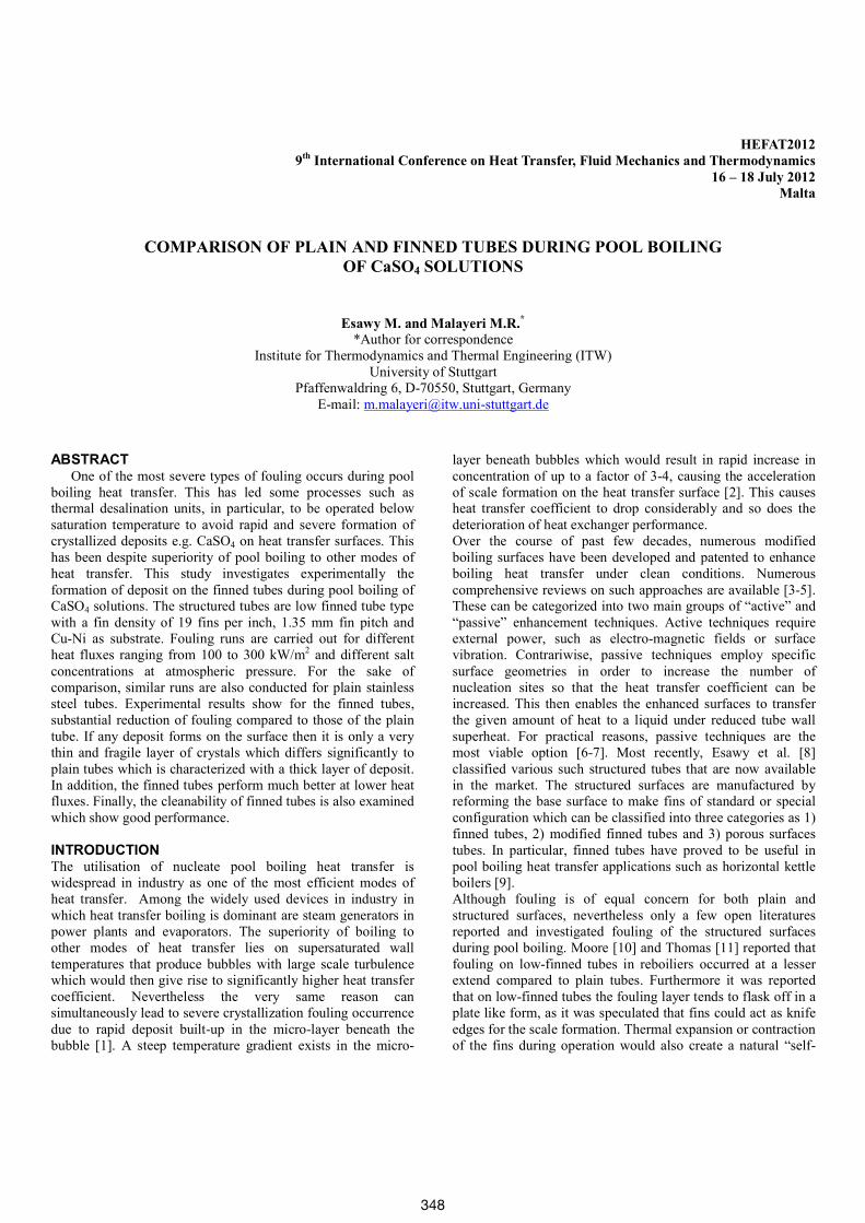
Effect of CaSO4 concentration Fig. 9 shows the influence of calcium sulphate concentration on the fouling behaviour of the finned tubes in terms of fouling resistance for a heat flux of 200 kW/m2. The results show how the fouling resistance strongly affected by decreasing the calcium sulphate concentration from 1.6 g/L to 1.2 g/L. Also for a concentration of 1.6 g/L, fouling resistance reaches its corresponding asymptotic value after 1200 minutes, while for 1.2 g/L, this time is approximately 100 minutes with a 55% reduction in the fouling resistance. As discussed before, by decreasing the CaSO4 concentration, the micro-layer
352
supersaturation decreases which leads to decrease in the deposition rate of calcium sulphate on the surface. Also, decreasing CaSO4 concentration results in a lower heat transfer performance due to changes in the mechanisms of bubble formation associated with the changing physical properties of the solution, particularly the surface tension [15].
Fig. 9 Effect of CaSO4 concentration on the fouling resistance of the finned tube for a heat flux of 200kW/m2
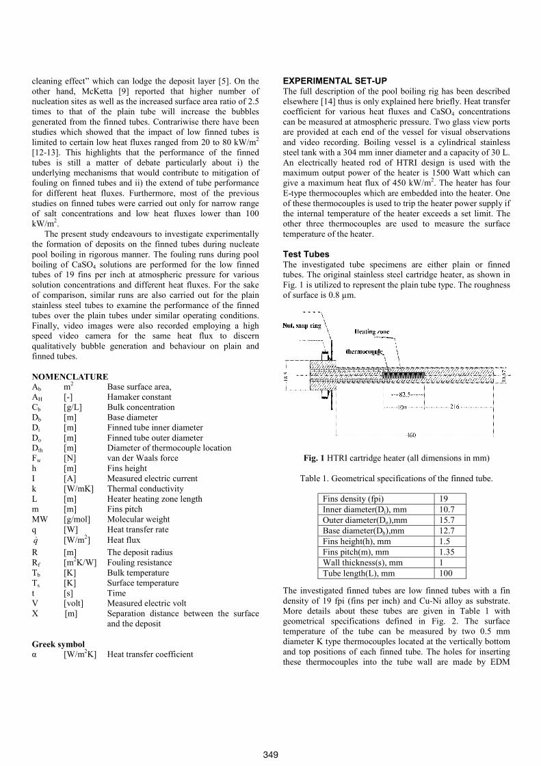
Comparisons between Plain and Finned TubesThe important feature of finned tubes is their fouling behaviour relative to plain tubes when subjected to similar operating conditions. As reported by McKetta [17] the good performance of the finned tubes over the plain tubes not only because of the number of nucleation sites but also due to the strong bubbles created on the finned tubes and the increased surface area ratio over the plain tubes. Fig. 10 shows the comparisons of the fouling resistance for the finned and plain tubes for a given concentration of 1.6 g/L and various heat fluxes of 100, and 300 kW/m2. It can be seen that at high heat flux of 300 kW/m2, the finned tube fouling resistance increases slowly with time until it reaches an asymptotic value of 1x10⁻⁵ m2K/W after 1200 minutes. Whereas for the plain tube, it increases rapidly until the surface temperature of the heater reaches its critical value of 170oC after approximately 950 minutes which leads to terminate the run automatically with corresponding fouling resistance of 1.7x10⁻⁴ m2K/W. It is evident that, the fouling resistance could be reduced by 95% in case of finned tube compared with the plain one for at the same heat flux of 300 kW/m2. As discussed before, the reason for this attributes to the effect of the generated bubbles on the finned tube, which make a higher degree of turbulence and eddies than those of plain tubes. This eddies could help for better removal of the initial deposit particles. On the other hand, it was observed that bubbles generated on the finned tubes are more spherical with shorter attachment time which expected not to allow a steep temperature gradient as one would expect for the plain tubes. In addition, the presence of the fins itself reduces the tube surface temperature significantly compared with the plain one. This can
lead to reduce the fouling resistance as the surface temperature decreases, the fouling rate decreases. The trend is different in case of low heat flux of 100 kW/m2 as shown in the same figure, in which the finned tube fouling resistance fluctuates approximately around zero. The reason for this due to the effect of both low surface temperature and the generated bubbles mechanism mentioned before.
0 200 400 600 800 1000 1200 1400
0.0
4.0x10⁻⁵
8.0x10⁻⁵
1.2x10⁻⁴
1.6x10⁻⁴
2.0x10⁻⁴
(4)
(1)
(2)
(3)
1.6 g/L CaSO4(1) Plain tube at 300 kW/m2
(2) Plain tube at 100 kW/m2
(3) Finned tube at 300 kW/m2
(4) Finned tube at 100 kW/m2
time, min
Fig. 10 Comparison of fouling resistance for plain and finned tubes at a heat flux of 300 kW/m2 and 200 kW/m2 with a concentration of 1.6 g/L.
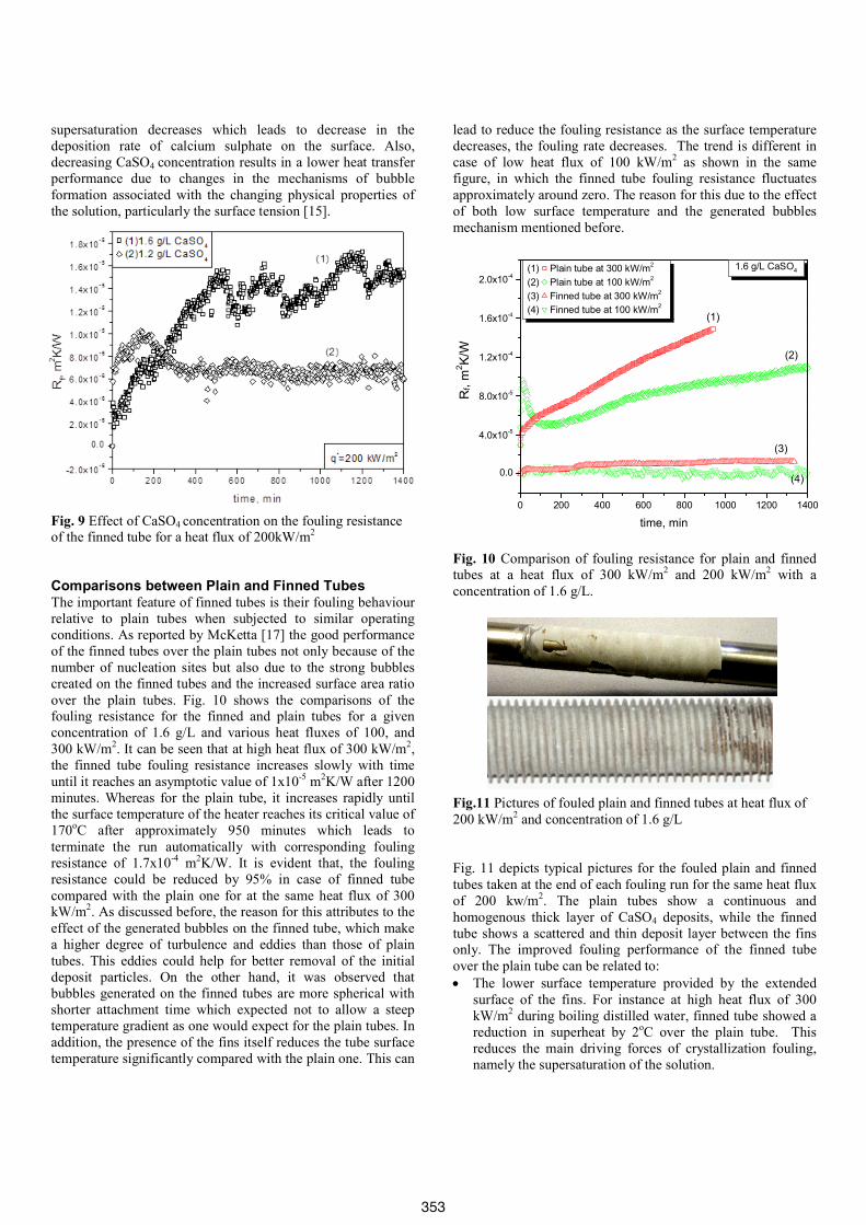
Fig.11 Pictures of fouled plain and finned tubes at heat flux of 200 kW/m2 and concentration of 1.6 g/L
Fig. 11 depicts typical pictures for the fouled plain and finned tubes taken at the end of each fouling run for the same heat flux of 200 kw/m2. The plain tubes show a continuous and homogenous thick layer of CaSO4 deposits, while the finned tube shows a scattered and thin deposit layer between the fins only. The improved fouling performance of the finned tube over the plain tube can be related to:
The lower surface temperature provided by the extended surface of the fins. For instance at high heat flux of 300 kW/m2 during boiling distilled water, finned tube showed a reduction in superheat by 2oC over the plain tube. This reduces the main driving forces of crystallization fouling, namely the supersaturation of the solution.
353
Bubble growth and detachment behaviour on finned tubes differ substantially from plain tubes. Due to the larger number of nucleation sites, more bubbles are generated from fin areas leading to higher degree of turbulence which improves removal of the initial crystals from the surface. The wiping action of bubbles growing at the base of the fins and moving along the fin surfaces. No deposits were hence found on the sides of fins above their base. The fins themselves inhibit the formation of a continuous, strongly attached fouling layer, hence promoting a scattered deposit pattern which is more susceptible to removal by shear forces. The thermal expansion and contraction of the fins during operation create a natural “self-cleaning effect” which can break the fouling layer.
Reproducibility of Fouling Results for the Finned Tubes Reproducibility of the fouling experimental data is one of the most important parameters used to ascertain the fouling behaviour of the heat transfer surfaces under the same operating conditions. To evaluate the reproducibility of the fouled finned tubes, each experiment was repeated twice at the same operating conditions. Fig. 12 show the reproducibility of the fouled finned tubes for a heat flux of 200 and 300 kW/m2 for a given CaSO4 concentration of 1.6 g/L. It can be seen from the figure that, both of the two fouling trails approximately have the same fouling trend in terms of fouling resistance, which show a good performance.
Fig. 12 Reproducibility of the finned tube for a heat flux of 300 and 200 kW/m² and concentration of 1.6 g/L
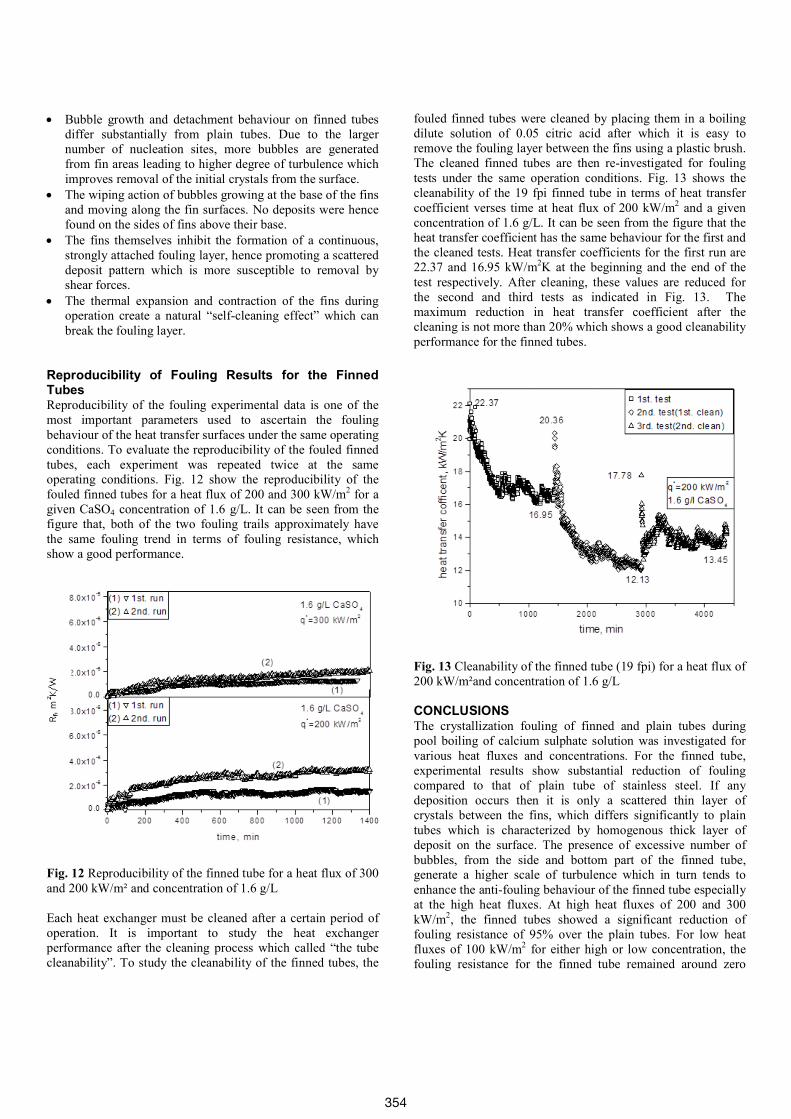
Each heat exchanger must be cleaned after a certain period of operation. It is important to study the heat exchanger performance after the cleaning process which called “the tube cleanability”. To study the cleanability of the finned tubes, the
fouled finned tubes were cleaned by placing them in a boiling dilute solution of 0.05 citric acid after which it is easy to remove the fouling layer between the fins using a plastic brush. The cleaned finned tubes are then re-investigated for fouling tests under the same operation conditions. Fig. 13 shows the cleanability of the 19 fpi finned tube in terms of heat transfer coefficient verses time at heat flux of 200 kW/m2 and a given concentration of 1.6 g/L. It can be seen from the figure that the heat transfer coefficient has the same behaviour for the first and the cleaned tests. Heat transfer coefficients for the first run are 22.37 and 16.95 kW/m2K at the beginning and the end of the test respectively. After cleaning, these values are reduced for the second and third tests as indicated in Fig. 13. The maximum reduction in heat transfer coefficient after the cleaning is not more than 20% which shows a good cleanability performance for the finned tubes.
Fig. 13 Cleanability of the finned tube (19 fpi) for a heat flux of 200 kW/m²and concentration of 1.6 g/L
CONCLUSIONS The crystallization fouling of finned and plain tubes during pool boiling of calcium sulphate solution was investigated for various heat fluxes and concentrations. For the finned tube, experimental results show substantial reduction of fouling compared to that of plain tube of stainless steel. If any deposition occurs then it is only a scattered thin layer of crystals between the fins, which differs significantly to plain tubes which is characterized by homogenous thick layer of deposit on the surface. The presence of excessive number of bubbles, from the side and bottom part of the finned tube, generate a higher scale of turbulence which in turn tends to enhance the anti-fouling behaviour of the finned tube especially at the high heat fluxes. At high heat fluxes of 200 and 300 kW/m2, the finned tubes showed a significant reduction of fouling resistance of 95% over the plain tubes. For low heat fluxes of 100 kW/m2 for either high or low concentration, the fouling resistance for the finned tube remained around zero
354
compared with its values of plain tubes. In addition the good performance of the finned tubes over the plain tubes under fouling conditions were studied and figured out. The cleanability and the reproducibility of the finned tubes were examined which showed good performance.
REFERENCES [1] Malayeri, M.R., and Müller-Steinhagen, H., Initiation of
CaSO4 scale formation on heat transfer surfaces under pool boiling conditions, Heat Transfer Eng,. Vol. 28, No. 3, 2007, pp. 240-247.
[2] Jamialahmadi, M., and Müller-Steinhagen, H., Scale formation during nucleate boiling - A review, Corrosion Reviews, Vol. 11, Part 1&2, 1993, pp. 25-54.
[3] Thome, J.R., Enhanced boiling heat transfer, Hemisphere Publishing Corp., New York, 1990, pp. 40.
[4] Webb, R.L., Principles of Enhanced Heat Transfer, John Wiley and Sons, Inc., 2005, pp. 3-10.
[5] Bergles, A.E., Enhancement of pool boiling, Int. J. Refrigeration, Vol. 20, 1997, pp.545-551.
[6] Ayub, A.H., and Bergles, A.E., Pool boiling enhancement of a modified GEWAT surface in water, Int. J. Heat Transfer, Vol. 110, 1988, pp. 266-268.
[7] Bergles, A.E., ExHFT for fourth generation heat transfer technology, J. Experimental Thermal Fluid Science, Vol. 26, 2002, pp. 335-344.
[8] Esawy, M., Malayeri, M.R. and Müller-Steinhagen, H., Mechanism of crystallization fouling during pool boiling of finned tubes, IWTC, Hurghada, Egypt, 2009, pp. 1417-1430.
[9] McKetta, J.J., Encyclopedia of chemical processing and design, Vol. 21, Marcel Dekker Inc., New York, 1984, pp. 474.
[10] Moore, J., Fin tubes foil fouling for scaling services, J. chemical processing, August, 1974, pp. 8-10.
[11] Thomas, C., Recent developments in the manufacturing and application of integral low fin tubing in titanium and zirconium, in Zirconium/Organics Conference, Gleneden Beach, Oregon, Proceedings, 1997, p 169.
[12] Bergles, A.E., and Somerscales, E.F.C., The effect of fouling on enhanced heat transfer equipment, J. Enhanced Heat Transfer, Vol. 2, 1995, pp. 157-166.
[13] Somerscales, E.F.C., and Curcio, L.A, Effect of calcium sulphate on pool boiling of enhanced surfaces, ASME WAM, Dallas, Texas, 1990.
[14] Esawy, M., Malayeri, M.R. and Müller-Steinhagen, H., Crystallization fouling of finned tubes during pool boiling: Effect of fin density, J. Heat and Mass Transfer, Vol. 46, 2010, pp. 1167-1176.
[15] Malayeri, M.R., Müller-Steinhagen, H. and Bartlett, T.H., Fouling of tube bundles under pool boiling conditions, J. Chem. Eng. Sci., Vol. 60, part 6, 2005, pp. 1503-1513.
[16] Bornhorst, A., Zhao, Q. and Müller-Steinhagen, H., Reduction of scale formation by ion implantation and magnetron sputtering on heat transfer surfaces, J. Heat Transfer Eng., Vol. 20, part 2, 1999, pp. 6-14.
[17] McKetta, J.J., Heat transfer design methods, Marcel Dekker Inc., New York, 1992, pp. 154.
355