comparison of spherical and membrane large lng … conferences/2005/sds... · comparison of...
TRANSCRIPT

© Gastech 2005
GASTECH 2005
Comparison of Spherical and Membrane Large LNG
Carriers in Terms of Cargo Handling
Author Kiho Moon, Chief Researcher Co-authors Daejun Chang, Senior Researcher
Donghun Lee, Researcher
Hyundai Industrial Research Institute
Myung-Bae Kim, General Manager Ho-Jong Ahn, General Manager Jong-Pil Ha, General Manager,
Project Planning Department 2
Hyundai Heavy Industries, Co., Ltd.

© Gastech 2005 Moon 2
Comparison of Spherical and Membrane Large LNG Carriers
in Terms of Cargo Handling
Kiho Moon*, Daejun Chang, Donghun Lee, Myung-Bae Kim, Ho-Jong Ahn and Jong-Pil Ha
Hyundai Heavy Industries, Dong-Ku, Ulsan, Korea
ABSTRACT This study presents a comprehensive comparative analysis of spherical and membrane large LNG carriers with respect to
cargo handling. The spherical Moss and the Mark III membrane types have the capacity of 185,000 m3 and 204,000 m3,
respectively. The study includes analyses on boil-off gas generation rate, cargo tank warm-up and cooldown, cargo
offloading, residual cargo handling, and comparative safety analysis. The boil-off gas generation rate is estimated as a
function of insulation thickness. For a carrier without a steam turbine propulsion system, irrespective of the types, the
boil-off gas should be liquefied in a reliquefaction unit. The heat ingress into the piping and its elements are found to
have a significant influence on the gas temperature entering the unit. Tank warm-up and cooldown study shows the
flexibility mainly governed by the thermal stress and consequently the plausible tank temperature variation limits. The
two types of LNG carriers show little variation in cargo offloading rate, but considerable difference in the amount of
residual cargo. This residual cargo should be treated in a proper way. The comparative safety analysis of the two LNG
carriers shows the relative advantages and disadvantages over each other.
----------------------------------------------------------------------------------------------------------------------------
*To whom all correspondence should be addressed.
© Gastech 2005 Moon 3
1 INTRODUCTION
The LNG carriers are designed, constructed and equipped to carry cryogenic liquefied natural gas (LNG) stored at a
minimum temperature of -163 oC and atmospheric pressure with density of 500 kg/m3. The spherical and membrane
types are accepted worldwide as cryogenic cargo containment systems.
The spherical independent tank (by Kvaerner-Moss Technology) consists of insulated single wall spherical tank,
supported by a vertically built skirt. The skirt is connected with the tank around the periphery of the equator. The cargo
tank material is aluminum alloy. Each cargo tank is seated in a separate cargo hold with the tank skirt mounted directly
on the foundation deck. The leak protection system prevents hull structural members from direct contact with cryogenic
liquid cargo in accordance with the Classification Society’s requirements. The Mark III (by Gaztransport & Technigaz)
reduces insulation thickness and weight significantly.
The insulation of tanks, irrespective of its type, is designed and constructed to accommodate the boil-off rate as
specified, for example, 0.15%/day. The LNG cargo tank has a filling limit. Especially for the membrane type, voyages sea
with cargo tank filling ratio between 10% of the tank lengthwise and 80% height wise are prohibited without rigorous
safety studies due to sloshing.
A number of technologies to design the cargo hold and handling systems have entered into practice for LNG carriers.
Evaluation for ensuring the structural integrity and the precise design of the cargo system is the most important concern.
Numerous economical reasons lead to a significant increase in tank capacity and innovations in cargo handling systems
such as BOG reliquefaction systems and propulsion systems such as dual fuel electric driven or diesel driven engines, etc.
The most critical concern of the LNG transportation societies is how to meet and manage the new environmental and
economical challenges.
LNG carriers should be adequately and safely designed for storing and handling their cryogenic cargo. This study
presents a comparative analysis of a spherical and membrane-typed cryogenic cargo hold and cargo handling system.
Evaluation of a cargo handling system is one of the most important elements in this study.

© Gastech 2005 Moon 4
2 VISIBILITY OF LNG CARRIER
Cargo containment systems have influence not only on the transport capacity but also on the visibility.
This section compared a spherical and a membrane type LNG carrier. Figure 1 shows the each ship’s visibility at ballast
condition. The shaded areas represent the blind zone.
2.77MM 1.77M
BLIND ZONE
2.5°
2.5° 0.3
1M
BLIND ZONE
2.12M
(a) Spherical 185K LNGC
2.77LL 1.77L
BLIND ZONE
0.38
L
BLIND ZONE
(b) Membrane 204K LNGC
Figure 1. Extent of blind zone and invisible length at ballast condition (M � 1.05L)
As shown in Figure 1, the spherical typed-LNG carrier has a lower visibility than the membrane type. Both types have
almost the same principal ship dimensions except cargo capacity.
3 CARGO OPERATION
3.1 Emergency discharge of cargo
The spherical LNGC is capable of pressure discharging of cargo in emergencies when all cargo pumps in a cargo tank fail.
Pressure discharging transfers LNG in the tank containing the failed cargo pumps to other tanks in normal condition. The
procedure may also perform at berthed condition if permitted by the terminal and the regulatory bodies concerned. In
case of the pressure discharge at sea, the operation should perform under still water condition.
The pressure discharge procedure accompanies the tank pressure peaks reaching about 1.9 barg at pressurization.
Therefore, the set pressure of the tank pressure relief valve should be adjusted higher under the supervision of the
master and the changes recorded in the ship’s log in accordance with the requirement of the rules.
During emergency pressure discharge from the tank, the vapor returns from a combined high- duty heater and
vaporizer. The vaporizer capacity is sufficiently covered to maintain cargo tank pressure during emergency pressure
discharge of cargo. In order for the operation to be controlled at low pressure, it is highly recommended to monitor the
rate of pressure increase in the cargo tank. Ballast adjustment is also performed to keep the ship balanced during
emergency discharge.

© Gastech 2005 Moon 5
On the other hand, the Mark III LNGC has an emergency cargo pump for discharging LNG in the case when both
cargo pumps fail. Each tank has a column where an electric motor-driven emergency cargo pump is lowered and a
column with a nitrogen purge connection is to be used as an emergency cargo pump.
In principle, one emergency cargo pump is installed on the ship to cover all cargo tanks. The emergency cargo pump
is handled through the top of cargo tanks without opening the tanks. Lowering of the emergency cargo pump in all tanks
is to be demonstrated before the gas trial and the pump will be kept in the lowered position in the last tank for an
operation test during the gas trial.
The emergency discharge operation is shown in Figure 2.
Figure 2. Emergency discharge operation for spherical (left) and membrane (right) type cargo containment systems
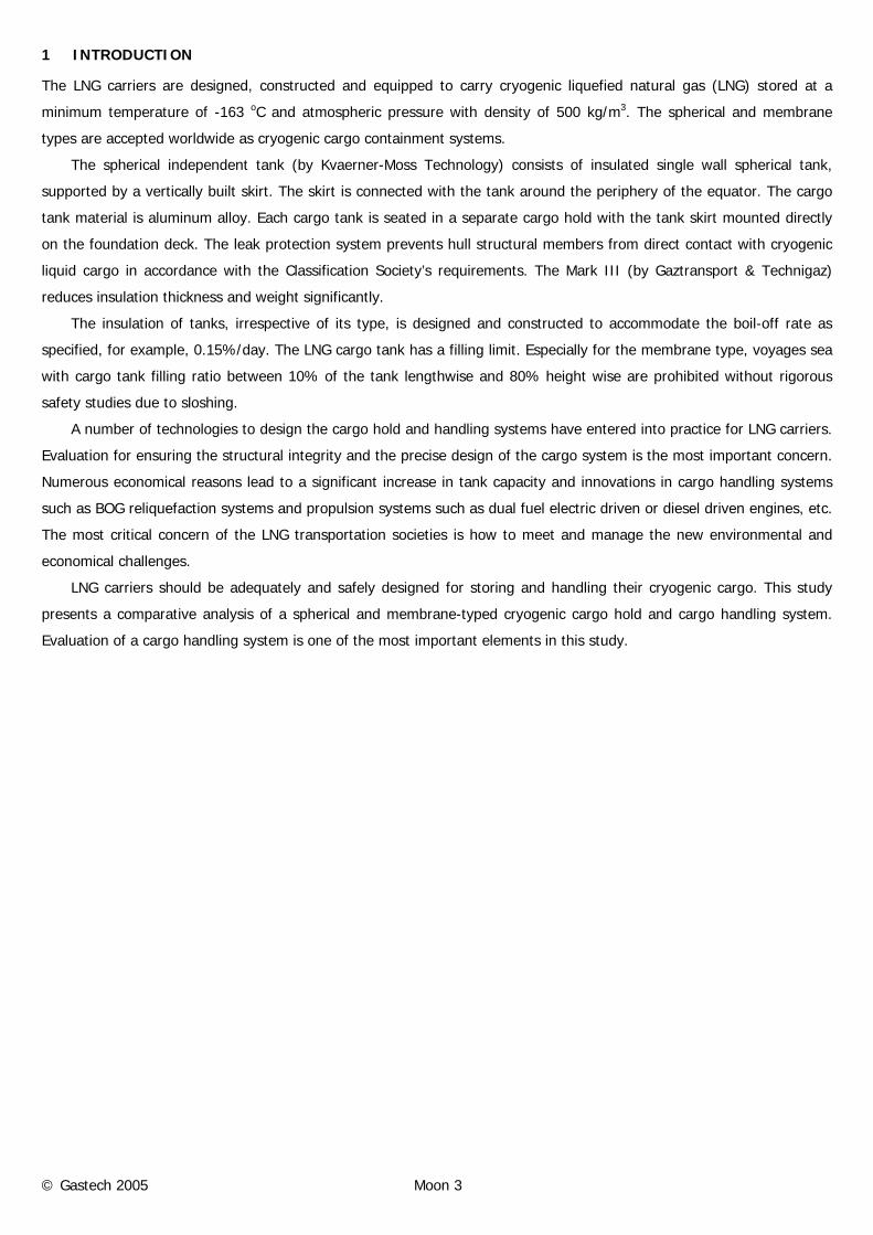
3.2 LNG Jettisoning
A containment or insulation system failure in one or more cargo tanks may necessitate the jettisoning of cargo from that
particular cargo tank to the sea. This is carried out using a single main cargo pump discharging LNG through a portable
jettisoning nozzle fitted on the ship’s manifold.
Since jettisoning of LNG creates hazardous conditions, the following deserve due consideration.
- All circumstances of failure must be carefully evaluated before the decision to jettison cargo is taken.
- All relevant fire fighting equipment must be manned and maintained in a state of readiness during the entire
operation.
- All accommodations, other openings and all vent fans must be secured.
- The No-Smoking rule must be rigidly enforced.
- The water curtain on the side of the jettison is to be running to protecting the ship’s structure.
Weather conditions and the heading of the vessel relative to the wind must be considered to ensure that the
jettisoned liquid and resultant vapor cloud are carried away from the vessel.
The portable jettisoning nozzle is capable of being mounted on any liquid manifolds, projecting 3 m over the ship’s
side and providing an outlet velocity of 40 m/s when supplied by two cargo pumps at rated capacity. The operation
procedure is shown in Figure 3.
Emergency Discharge
Emergency Discharge
Vapor In
Vapor In
© Gastech 2005 Moon 6
Figure 3. Emergency jettisoning operation for spherical (left) and membrane (right) type cargo containment systems
3.3 Cargo Tank Cool-down
Roughly speaking, analysis of cargo tank cool-down consists of two parts. The first part is to determine for a given spray
rate the resultant temperature drops in the gas phase, the internal tower, and the tank shell.
These are obtained by solving the transient energy balance which considers the heat flow into the tank through the
insulation and the cooling effect of the LNG spray delivered at -163℃.
The second part is to estimate the thermal stress using a FEM tool, which receives various predefined conditions
from the part.
In general, it is assumed that the tank wall is a lumped mass, and that all parts of the tank have the same
temperature. The gas phase temperature and heat transfer coefficients play a role of time-dependent boundary
conditions. HYSYS.Plant, a dynamic process simulator, was used to calculate the thermal distribution during cool-down.
The temperature profile and the heat transfer coefficients were then used as boundary conditions for the FEM model
program. For the cool-down calculation of the LNG cargo tank, uniform gas temperature is assumed throughout the tank
at any instance of time. In addition, temperature at the tank wall and the internal tower are assumed to be uniform. In
the heat transfer calculation, the droplet evaporation on the tank wall is neglected. The main heat transfer mechanism of
the tank cool-down between the solid walls and surrounding gas is accounted for by natural convection.
The velocity of the fluid is assumed to observe the turbulent film model. That is, the velocity is zero on the heated
body, increases rapidly in a thin boundary layer adjacent to the body and has a vanished gradient far from the body. The
temperature gradient between stagnant fluid and solid body is produced by heat transfer. The fluid motion due to natural
convection results from buoyancy force arising from changes in density.
Tank cool-down for a spherical and membrane LNG Carrier is performed for the spray rate, and the results for
transient profiles of mass flow and temperature are shown in Figures 4 and 5. When the tank gas temperature reaches
the natural gas dew point, spray efficiency sharply decreases and then residual LNG appears. The tank wall temperature
is higher than that of the tank gas. Some of the residual LNG will evaporate when it contacts the wall. This results in a
somewhat lower tank wall temperature than predicted in the calculation.
LNG Jettisoning Vapor In
LNG Jettisoning Vapor In

© Gastech 2005 Moon 7
0
5000
10000
15000
20000
25000
0 4 8 12 16
Time, Hours
Mas
s Fl
owra
te, kg
/hr
SprayBoil-Off GasCondensate
0
5000
10000
15000
20000
25000
0 4 8 12 16
Time, Hours
Mas
s Fl
owra
te, kg
/hr
SprayBoil-Off GasCondensate
(a) Spherical (b) Membrane
Figure 4. Profiles of mass flow rate during cool-down
-200
-150
-100
-50
0
50
0 4 8 12 16
Time, Hours
Tem
pera
ture
, oC Natural Gas
Internal Tower
Inside Wall
Outside Wall
Insulation Center
Outside Insulation
Hold Space
Equator
Sensor
-200
-150
-100
-50
0
50
0 4 8 12 16
Time, Hours
Tem
pera
ture
, oC
NaturalGas
PrimaryBarrier
TopPlywood
PrimaryInsulation
Triplex
SecondaryInsulation
BackPlywood
Mastic
InnerHull
CompartmentAir
OuterHull
(a) Spherical
(b) Membrane
Figure 5. Temperature profiles with low rate changes of spray LNG and boil-off gas during cool-down
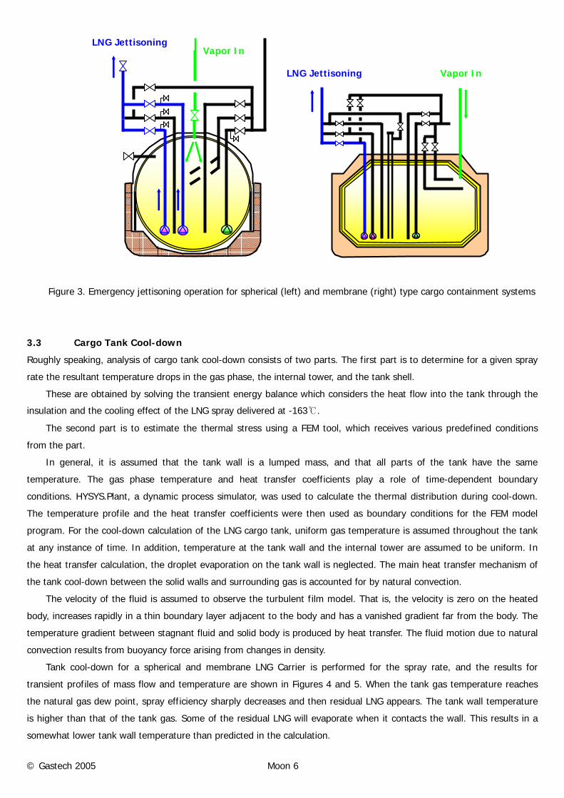
3.4 Cargo loading and offloading
Generally, cargo loading and offloading times are specified for the design of cargo pumps and pipes. Figures 6 and 7
show pressure drops of related lines and estimated loading and unloading times of typical membrane cargo tanks.
During loading and offloading operations, NPSH available varies since the cargo level inside the tank changes with
operation time. Discharge time is divided into several stages; the buildup period for starting pumps, the load stage and
the slowdown or stripping stage at the end of discharge. Spherical cargo tank design and evaluation has a similar
approach to those of LNG cargo pumps and pipes.
During the operations, the condition of the cargo containment and handling system should be continuously
monitored from the IAS and various safety protections should be provided to keep the system in a reliable state at all
times to evaluate their design. This study employs a dynamic simulation of all cargo handling processes for a rigorous
process monitoring.
© Gastech 2005 Moon 8
Tank 1Tank 2Tank 3Tank 4
A1A2A3A4
B_rB_l
C_l C_r
D2D3
F3F4 F2 F1
E1E4
0.03 bar
0.385 bar
0.038 bar
0.086 bar
0.148 bar0.126 bar0.104 bar
0.076 bar 0.086 bar 0.02 bar
0.379 bar
- 0.77 bar - 0.77 bar - 0.77 bar - 0.77 bar
Figure 6. Pressure loss in loading lines
Tank 124,564 m3
Tank 339,395 m3
Tank 435,018 m3
H
A1A2A3A4
B_rB_l
C_l C_r
D2D3
F3F4 F2 F1
E1E4
Tank 239,395 m3
Loading 7.4 hrUnloading 6.4 hr
Loading 11.5 hrUnloading 10.1 hr
Loading 11.5 hrUnloading 10.1 hr
Loading 9.6 hrUnloading 9.0 hr
Figure 7. Cargo loading and offloading time
4 BOR CALCULATION
The cargo tank is thermally insulated to achieve a boil-off rate not exceeding 0.15 percent by gross cargo volume per day
at 32℃ seawater temperature and 45℃ ambient air temperature.
There is a trade-off between boil-off rates and insulation thickness. Reducing the boil-off rate leads to an increase in
insulation cost, and vice versa. Figure 8 presents boil-off rates with insulation thickness. Estimation and prediction of boil-
off rates guides design of reliquefaction systems, cargo tank insulation systems and cargo handling systems.

© Gastech 2005 Moon 9
0.10
0.12
0.14
0.16
0.18
0.20
0.09 0.11 0.13 0.15 0.17
Secondary Insulation Thickness, mm
Boi
l-O
ff R
ate,
%/d
ay
10% Design MarginBOR 0.15%/day Limit
Figure 8. Secondary insulation thickness vs. boil-off rates for membrane cargo tank type
5 LNG reliquefaction system
Linde patents provide the basis for reliquefaction designs commercially available. The Linde process is composed of two
nitrogen compressors and a BOG (boil-off gas) compressor as shown in Figure 9. The cold stream from the nitrogen
expander is exchanged with BOG to be liquefied. The Tractebel process is much similar to the Linde process except for
elimination of the expansion valve.
The reliquefaction system simplifies the Linde process by removing the expansion valve and increasing energy
efficiency by optimizing the number of compressors for the nitrogen cycle. The outstanding features are a nitrogen-rich
purge, automatic capacity control, pre-cooling system and high reliability.
BOG Cycle
C
C
CE
N2 Cycle
BOG Cycle
CE
N2 Cycle
(a) Linde Process (b) Tractebel Process
Figure 9. Schematic process flow diagram for reliquefaction system
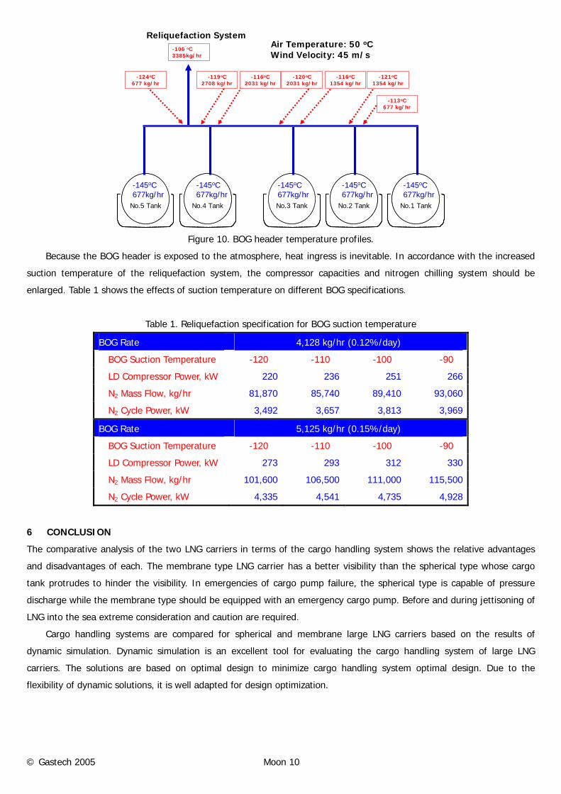
Process variables requiring precise estimation are BOG flow rates and their temperatures. Heat ingress through
piping and fittings is possibly mitigated by insulation of bellows, pipes and valves. Casing the BOG headers reduces the
heat loss from the forced convective heat transfer. As shown in Figure 10, preliminary inlet temperature of the
reliquefaction system is revealed.
© Gastech 2005 Moon 10
No.1 TankNo.2 TankNo.3 TankNo.4 TankNo.5 Tank
-145oC677kg/hr
-145oC677kg/hr
-145oC677kg/hr
-145oC677kg/hr
-145oC677kg/hr
-120oC2031 kg/hr
-121oC1354 kg/hr
-113oC677 kg/hr
-106 oC3385kg/hr
-116oC1354 kg/hr
-116oC2031 kg/hr
-119oC2708 kg/hr
Air Temperature: 50 oCWind Velocity: 45 m/s
-124oC677 kg/hr
Reliquefaction System
Figure 10. BOG header temperature profiles.
Because the BOG header is exposed to the atmosphere, heat ingress is inevitable. In accordance with the increased
suction temperature of the reliquefaction system, the compressor capacities and nitrogen chilling system should be
enlarged. Table 1 shows the effects of suction temperature on different BOG specifications.
Table 1. Reliquefaction specification for BOG suction temperature
BOG Rate 4,128 kg/hr (0.12%/day)
BOG Suction Temperature -120� -110� -100� -90�
LD Compressor Power, kW 220 236 251 266
N2 Mass Flow, kg/hr 81,870 85,740 89,410 93,060
N2 Cycle Power, kW 3,492 3,657 3,813 3,969
BOG Rate 5,125 kg/hr (0.15%/day)
BOG Suction Temperature -120� -110� -100� -90�
LD Compressor Power, kW 273 293 312 330
N2 Mass Flow, kg/hr 101,600 106,500 111,000 115,500
N2 Cycle Power, kW 4,335 4,541 4,735 4,928
6 CONCLUSION
The comparative analysis of the two LNG carriers in terms of the cargo handling system shows the relative advantages
and disadvantages of each. The membrane type LNG carrier has a better visibility than the spherical type whose cargo
tank protrudes to hinder the visibility. In emergencies of cargo pump failure, the spherical type is capable of pressure
discharge while the membrane type should be equipped with an emergency cargo pump. Before and during jettisoning of
LNG into the sea extreme consideration and caution are required.
Cargo handling systems are compared for spherical and membrane large LNG carriers based on the results of
dynamic simulation. Dynamic simulation is an excellent tool for evaluating the cargo handling system of large LNG
carriers. The solutions are based on optimal design to minimize cargo handling system optimal design. Due to the
flexibility of dynamic solutions, it is well adapted for design optimization.
© Gastech 2005 Moon 11
In addition, the membrane LNG carrier is capable of loading more than 8% LNG cargo in identical principal ship
dimensions. The boil-off gas rate is presented as a function of insulation thickness with a generally accepted boil-off gas
rate of 0.15%/day. Insulation and cargo handling system should be designed based on the specified BOR.
Estimated cool-down time for spherical type tank is 16 hours, satisfying the temperature requirement of the equator
sensor at -110℃. During cool-down, the maximum suction volume is observed to be 12,000 m3/hr at 1.5 hour. The
membrane cargo tank has a cool-down time of about 10 hours with a cargo tank atmosphere temperature of -140℃. The
maximum boil-off rate is predicted to be about 8,500 m3/hr at 1 hour.