operating guidance for membrane type lng carrier in partial filling condition · operating guidance...
TRANSCRIPT
OPERATING GUIDANCE FOR MEMBRANE TYPE LNG CARRIER IN PARTIAL FILLING CONDITION
Mirela Zalar, (V) BUREAU VERITAS / RESEARCH DEPARTMENT
ABSTRACT
One of the outcomes of extensive sloshing studies on partial fillings is the assessment of operational criteria for a 138,000 m3 membrane type LNG Carrier subjected to different environmental and navigation conditions that might cause undesired sloshing effects in partly filled tanks. This paper demonstrates the potential for safe operation of this class of vessel with intermediate fillings during the transient phase of LNG transfer. Operating guidance is presented in the form of navigation charts that serve as a guideline for ship operators to avoid critical environmental and navigation conditions while operating the ship in the partially filled condition.
KEY WORDS: LNG Carrier; Hydrodynamic; Sea-States; Sloshing; Resonance; Maximum Motion, Operability. INTRODUCTION Common operation of membrane type LNG Carriers is carried out with the cargo tank fully loaded at 95 percent of tank height or with minimum cargo contents of less then 5 percent during the return ballast voyage. A large number of sloshing studies carried out over the last 30 years resulted with the conclusion that severe sloshing effects can be mitigated by introducing large chamfers and reinforced insulation systems in the upper portion of the tanks. Hence, this modification of tank design enabled extending the allowable upper filling limit initially to 80 percent and then even to 70 percent of filling height for conventional LNG Carriers. Current practice demonstrates safe operation regarding the hull scantlings and containment system resistance on sloshing impact loads in the range of conventional fillings. However, recent LNG market growth with the subsequent demand for new LNG transportation concepts requires more flexible operations. Basic demand for partial filling operations is driven by the commercial trend towards small-spot trading, where particular concerns are given to safe LNG transfer during offshore loading and unloading. Sloshing, a violent behaviour of the liquid contents of tanks that are subjected to external forced motions, is a highly non-linear phenomenon that is affected by many parameters. Considerable attention is given to the energy of ship motion contained in the vicinity of the tank natural period. Resonant liquid flow can not be generalised and appears in different forms depending on the tank filling height, the predominant direction of excitation and the magnitude and composition of ship motion. One of the outcomes from Bureau Veritas’s extensive sloshing studies on partial fillings is the assessment of operational criteria for a 138,000 m3 membrane type LNG Carrier subjected to
different environmental and navigation conditions that might cause undesired sloshing effects in partly filled tanks. This paper demonstrates the possibility to operate vessels safely with intermediate fillings during the transient phase of LNG transfer. Operating guidance is presented in the form of navigation charts that serve as a guideline for ship operators to avoid critical environmental and navigation conditions while operating the ship in the partially filled condition. HYDRODYNAMIC ANALYSIS Hydrodynamic analysis is a key factor in each particular sloshing study and is aimed at evaluating overall vessel dynamic behaviour on waves that generate tank liquid response. Vessel response can be directly calculated using reliable numerical tools, or obtained experimentally from model tests. Hydrodynamic computations presented in this paper are performed by means of 3D-panel diffraction/radiation potential theory using the advanced Bureau Veritas program HydoSTAR (BV Reference Guide), fully validated through comparisons with semi-analytical studies, numerical results from recognized numerical tools and experimental results (Chen 2004). The HydroSTAR software uses efficient and advanced techniques, constantly improved by integrating the most recent theories and algorithms. Among the list of special features for offshore and naval applications, it includes a recently developed and validated dynamic coupling scheme between vessel motion and the motion of the liquid contents in partly filled tanks. This functionality has been shown to be particularly important for accurate prediction of dynamic behaviour of vessels carrying liquid cargo (Malenica et al. 2003). Basic considerations in hydrodynamic modelling are given to the vessel operation concept, with respect to the service definition, loading plan and environmental conditions provided by the operator.
Paper No. 2005- Zalar
ENVIRONMENTAL CONDITIONS Hydrodynamic Model The following general considerations are taken into account in the vessel hydrodynamic modelling:
Wave Scatter Diagram
The environmental conditions for sloshing analyses of ships in a seaway are described by the wave data that corresponds with the service specifications. Wind and current contributions on the 1st order ship response are not accounted for, as they only influence the mean position of the vessel.
o Ship hull form: to provide under-water hull shape, o General tank arrangement, to provide tank dimensions and
geometry for dynamic coupled analysis, o Loading conditions, to provide draught, hydrostatic and
mechanical properties, o Ship speeds & headings: to provide a ship service
benchmark. Typical environmental conditions considered in sloshing analyses correspond to the one of the following:
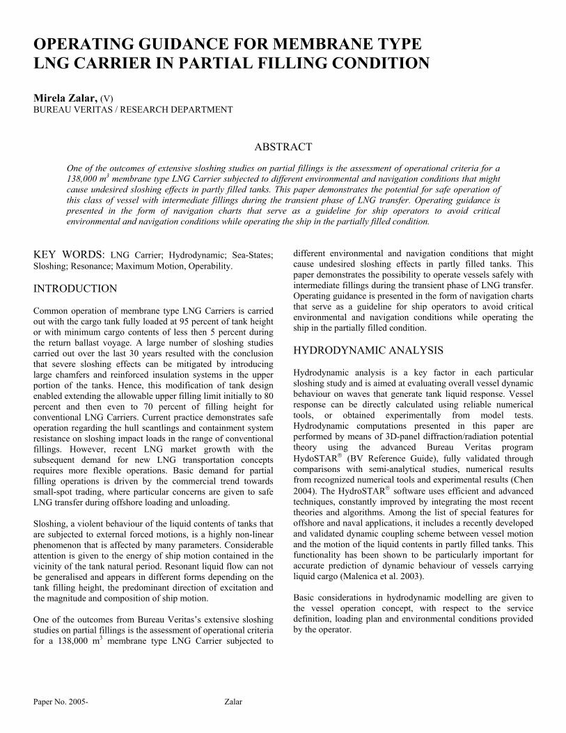
The geometry of the hydrodynamic model is typically developed from the vessel lines-plan or vessel offsets with the buoyant volume shape represented by a series of flat quadrilateral or triangular panels. The hydrodynamic model accounting for coupling effects due to the interaction of vessel motion and tank liquid motion is composed of the ship hull and tanks as a combined 3D-panel mesh (Figure. 1).
o North Atlantic wave scatter diagram IACS Res. 34 for world wide navigation,
o Directional wave scatter diagrams of all areas on expected routes (if required and specified),
o Directional wave scatter diagrams for the terminal site. Wave scatter diagrams represent the probability of occurrence associated with combinations of wave zero-crossing periods Tz and significant wave height Hs. A standard wave scatter diagram for unrestricted service is given in Table 1, extracted from IACS Recommendation 34 (IACS 2000). 100,000 records of wave events in the North Atlantic represent the probability of occurrence during approximately 20 years. The most extreme sea-state appearances are indicated with grey fields.
Figure 1: 3D-panel hydrodynamic model; generic (left); coupled (right) Table 1: Wave scatter for North Atlantic, by IACS Res. 34 Hs (m) 1.5 2.5 3.5 4.5 5.5 6.5 7.5 8.5 9.5 10.5 11.5 12.5 13.5 14.5 15.5 16.5 17.5 18.5 SUM
0.5 0 0 1 134 866 1186 634 186 37 6 1 0 0 0.0 0.0 0.0 0.0 0.0 30501.5 0 0 0 29 986 4976 7738 5570 2376 704 161 31 5 1 0 0.0 0.0 0.0 225752.5 0 0 0 2 198 2159 6230 7450 4860 2066 645 160 34 6 1 0.2 0.0 0.0 238103.5 0 0 0 0.2 35 696 3227 5675 5099 2838 1114 338 84 18 4 1 0.1 0.0 191284.5 0 0 0 0 6 196 1354 3289 3858 2686 1275 455 131 32 7 1 0.2 0.0 132895.5 0 0 0 0 1 51 498 1603 2373 2008 1126 464 151 41 10 2 0.4 0.1 83286.5 0 0 0 0 0.2 13 167 690 1258 1269 826 387 141 42 11 3 0.5 0.1 48067.5 0 0 0 0 3 52 270 594 703 525 277 112 37 10 3 0.6 0.1 25868.5 0 0 0 0 0 1 15 98 256 351 297 175 78 28 8 2 0.5 0.1 13099.5 0 0 0 0 0 0.2 4 33 102 160 152 99 48 19 6 2 0.4 0.1 62610.5 0 0 0 0 0 0 1 11 38 68 72 52 27 11 4 1 0.3 0.1 28511.5 0 0 0 0 0 0 0.3 3 13 27 31 25 14 6 2 1 0.2 0.1 12412.5 0 0 0 0 0 0 0.1 1 4 10 13 11 7 3 1 0.4 0.1 0 5113.5 0 0 0 0 0 0 0 0.3 1 4 5 5 3 2 1 0.2 0.1 0 2114.5 0 0 0 0 0 0 0 0.1 0.4 1 2 2 1 1 0.3 0.1 0 0 815.5 0 0 0 0 0 0 0 0 0.1 0.4 1 1 1 0.3 0.1 0.1 0 0 316.5 0 0 0 0 0 0 0 0 0 0.1 0.2 0.2 0.2 0.1 0.1 0 0 0 1SUM 0 0 1 165 2091 9280 19922 24879 20870 12898 6245 2479 837 247 66 16 3 1 100000
Tz (s)
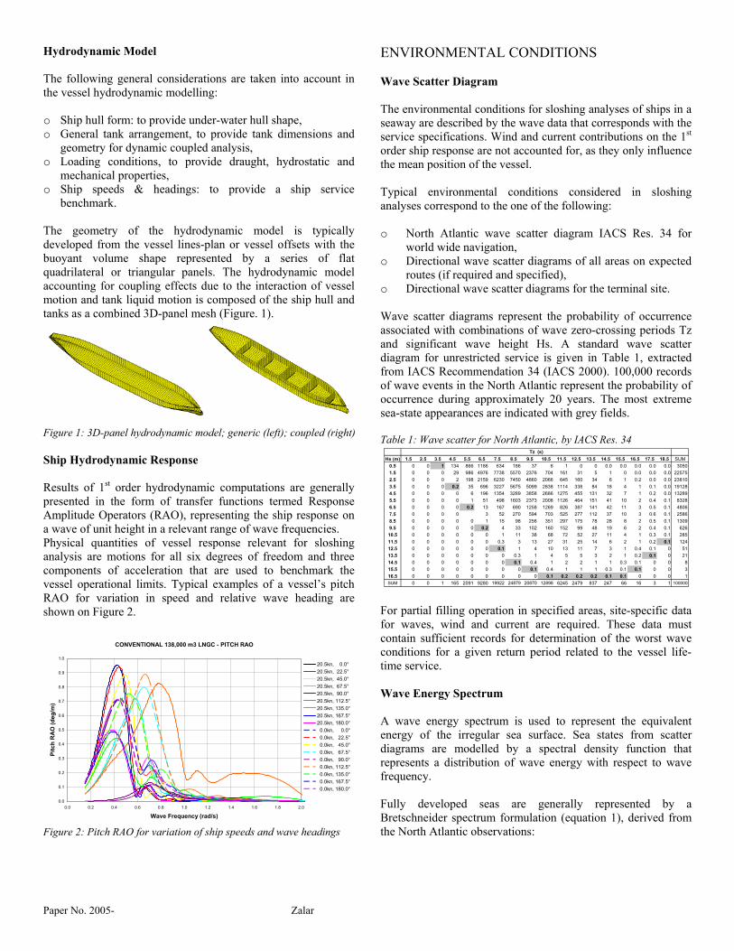
Ship Hydrodynamic Response Results of 1st order hydrodynamic computations are generally presented in the form of transfer functions termed Response Amplitude Operators (RAO), representing the ship response on a wave of unit height in a relevant range of wave frequencies. Physical quantities of vessel response relevant for sloshing analysis are motions for all six degrees of freedom and three components of acceleration that are used to benchmark the vessel operational limits. Typical examples of a vessel’s pitch RAO for variation in speed and relative wave heading are shown on Figure 2.
For partial filling operation in specified areas, site-specific data for waves, wind and current are required. These data must contain sufficient records for determination of the worst wave conditions for a given return period related to the vessel life-time service.
CONVENTIONAL 138,000 m3 LNGC - PITCH RAO
0.0
0.1
0.2
0.3
0.4
0.5
0.6
0.7
0.8
0.9
1.0
0.0 0.2 0.4 0.6 0.8 1.0 1.2 1.4 1.6 1.8 2.0
Wave Frequency (rad/s)
Pitc
h R
AO
(deg
/m)
20.5kn, 0.0°20.5kn, 22.5°20.5kn, 45.0°20.5kn, 67.5°20.5kn, 90.0°20.5kn, 112.5°20.5kn, 135.0°20.5kn, 167.5°20.5kn, 180.0° 0.0kn, 0.0° 0.0kn, 22.5° 0.0kn, 45.0° 0.0kn, 67.5° 0.0kn, 90.0° 0.0kn, 112.5° 0.0kn, 135.0° 0.0kn, 167.5° 0.0kn, 180.0°
Wave Energy Spectrum A wave energy spectrum is used to represent the equivalent energy of the irregular sea surface. Sea states from scatter diagrams are modelled by a spectral density function that represents a distribution of wave energy with respect to wave frequency. Fully developed seas are generally represented by a Bretschneider spectrum formulation (equation 1), derived from the North Atlantic observations: Figure 2: Pitch RAO for variation of ship speeds and wave headings
Paper No. 2005- Zalar
5
25.124
425.1
)(
4
ωω
ωωω
ξ
−
=
p
eHS sp (1)
Where: S : Wave energy density (m2 s). ω : Angular frequency of wave component (rad/s). ωp = 2π/Tp = 2π /(1.41 Tz) : Peak wave frequency (rad/s). SPECTRAL ANALYSIS The absolute responses in short term predictions of vessel hydrodynamic behaviour are determined by means of spectral analysis, obtained for each of the six degrees of freedom defined by the motion RAOs i.e., transfer functions H(ωe), for all combinations of vessel speed and heading. The energy associated with vessel motion response is calculated for each given sea-state modelled by the wave energy spectrum Sξ(ωe), distributed per wave frequency. Results are presented in the form of a response energy density spectrum Rx(ωe), with translational or rotational units of m2s/rad or deg2s/rad, respectively:
2)()()( eeex HSR ωωω ξ ⋅= (2) Response spectral moments mn (in m2/sn or deg2/sn) are given in general form:
∫∞
⋅=0
)( eneexn dRm ωωω (3)
Using equation 3, response spectral moments m0 and m2 are calculated to formulate motion 1/1000th amplitude (equation 4) required for operability limits, 1/10th amplitude (equation 5) representing magnitude of sloshing excitation and mean zero-crossing period (equation 6) associated with the tank resonance period for the resonance state.
01000/1 72.3 mR = (4)
010/1 54.2 mR = (5)
2
02mmRTZ π= (6)
TANK RESONANCE The objective of tank resonance analysis is to identify the relationship between tank filling height and tank natural period, which can be presented in the form of tank resonance curves. In a first approximation, tank resonance curves are traced according to the linear potential theory formulation, for the both, longitudinal and transverse directions (BV Guidance Note,
1984). The theoretical formulation is valid only for rectangular tanks and small amplitude motions, and can only serve as a preliminary prediction of tank resonance period. In more refined procedures, tank resonance period is determined by means of numerical simulations or small-scale tank model tests utilizing the period scanning method: the initial amplitude of dominant ship motion is imposed on the tank and the period of motion is systematically varied with a small time step around the theoretical resonance period. Finally, the resonance period is indicated by the highest value of: o Maximum mean kinetic energy from numerical simulation,
or o Maximum impact pressure measured by all pressure gauges
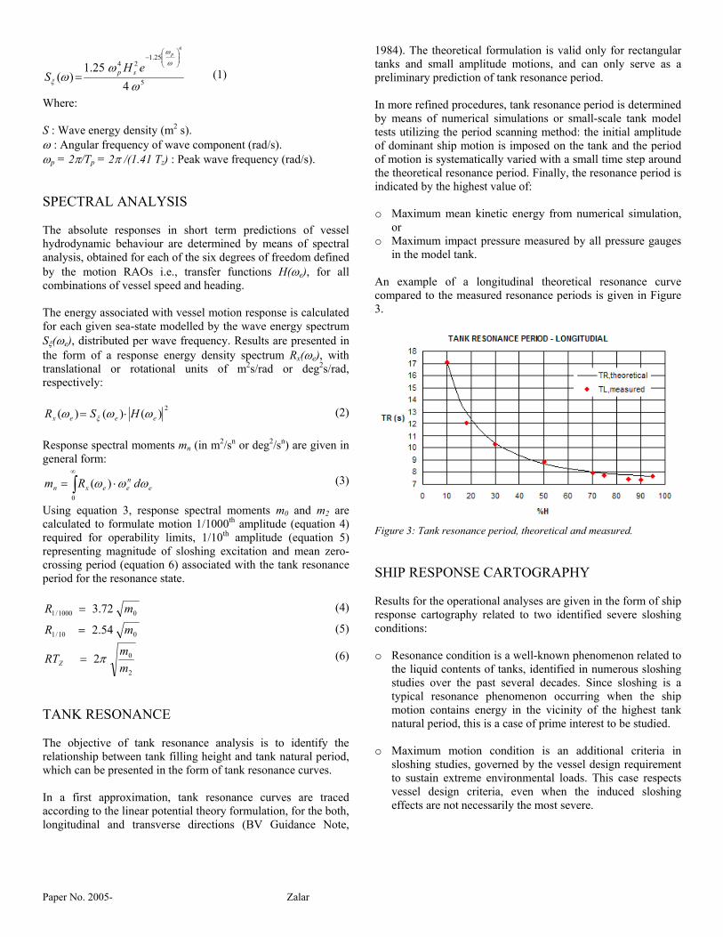
in the model tank. An example of a longitudinal theoretical resonance curve compared to the measured resonance periods is given in Figure 3.
Figure 3: Tank resonance period, theoretical and measured. SHIP RESPONSE CARTOGRAPHY Results for the operational analyses are given in the form of ship response cartography related to two identified severe sloshing conditions: o Resonance condition is a well-known phenomenon related to
the liquid contents of tanks, identified in numerous sloshing studies over the past several decades. Since sloshing is a typical resonance phenomenon occurring when the ship motion contains energy in the vicinity of the highest tank natural period, this is a case of prime interest to be studied.
o Maximum motion condition is an additional criteria in
sloshing studies, governed by the vessel design requirement to sustain extreme environmental loads. This case respects vessel design criteria, even when the induced sloshing effects are not necessarily the most severe.
Paper No. 2005- Zalar
0.1
0.1
0.20.2
02
0.3
0.3 0.3
0.4
0.4
0.4 0.4
0.5
0.50.5
0.5 0.5
0.6
0.6
0.6 0.6
0.7
0.70.7
0.7 0.7 0.7
0.8
0.8
0.8 0.8
0.9
0.9 0.90.9 0.9 0.9
WAVE ZERO-CROSSING PERIOD [s]
HE
AD
ING
[dg]
4 5 6 7 8 9 10 11 12 13 14 15 16 17 180.0
22.5
45.0
67.5
90.0
112.5
135.0
157.5
180.0
1.00.90.80.70.60.50.40.30.20.1
138,000 m3 LNGC - IACS NORTH ATLANTIC - V=20.5 knPITCH RESPONSE wrt
OPERATIONAL CONDITIONS & LONGITUDINAL TANK RESONANCE
TANK No2 PITCHFILLING PERIOD
0.1 H 14.8 - 20.7 s0.2 H 11.4 - 14.8 s0.3 H 9.8 - 11.4 s0.4 H 9.0 - 9.8 s0.5 H 8.5 - 9.0 s0.6 H 8.1 - 8.5 s0.7 H 7.9 - 8.1 s0.8 H 7.8 - 7.9 s0.9 H 7.7 - 7.8 s
RESONANCE LONGI.
PITCHAMPLITUDE [dg]
7.336.595.865.134.403.662.932.201.470.73
12% 79% 10% OCCURENCE
7.396.655.915.174.433.692.952.221.480.74
0.1
0.1
0.1
0.2
0.2
0.20.2
0.3
0.3 0.3
0.3 0.3 0.3
0.4
0.40.4
0.4 0.4
0.5
0.5
0.5 0.5
0.7
0.6
0.6 0.6 0.6
0.7
0.7 0.7
0.7 0.7 0.7
0.8
0.8 0.8
0.8 0.8
0.8
0.9 0.90.9 0.9
WAVE ZERO-CROSSING PERIOD [s]
HE
AD
ING
[dg]
4 5 6 7 8 9 10 11 12 13 14 15 16 17 180.0
22.5
45.0
67.5
90.0
112.5
135.0
157.5
180.0
1.00.90.80.70.60.50.40.30.20.1
138,000 m3 LNGC - IACS NORTH ATLANTIC - V=20.5 knSURGE RESPONSE wrt
OPERATIONAL CONDITIONS & LONGITUDINAL TANK RESONANCE
TANK No2 SURGEFILLING PERIOD
0.1 H 14.8 - 20.7 s0.2 H 11.4 - 14.8 s0.3 H 9.8 - 11.4 s0.4 H 9.0 - 9.8 s0.5 H 8.5 - 9.0 s0.6 H 8.1 - 8.5 s0.7 H 7.9 - 8.1 s0.8 H 7.8 - 7.9 s0.9 H 7.7 - 7.8 s
RESONANCE LONGI.
SURGEAMPLITUDE [m]
15.7114.1412.5711.009.437.866.294.713.141.57
12% 79% 10% OCCURENCE Figure 4: PITCH response at North Atlantic (IACS Res.34), V=20.5 kn Figure 7: SURGE response at North Atlantic (IACS Res.34), V=20.5 kn
0.1
0.1
0.1
0.2
0.2
0.3
0.3
0.3
0.3
0.4
0.40.4
0.40.4
0.5
0.5 0.5
0.50.5
0.5
0.6
0.60.6
0.6
0.6
0.7
0.70.7
0.70.7
0.7
0.8
0.8 0.8
0.8
0.8
0.8
0.9
0.9 0.90.90.9
0.9
WAVE ZERO-CROSSING PERIOD [s]
HE
AD
ING
[dg]
4 5 6 7 8 9 10 11 12 13 14 15 16 17 180.0
22.5
45.0
67.5
90.0
112.5
135.0
157.5
180.0
1.00.90.80.70.60.50.40.30.20.1
138,000 m3 LNGC - IACS NORTH ATLANTIC - V=0 knPITCH RESPONSE wrt
OPERATIONAL CONDITIONS & LONGITUDINAL TANK RESONANCE
TANK No2 PITCHFILLING PERIOD
0.1 H 14.8 - 20.7 s0.2 H 11.4 - 14.8 s0.3 H 9.8 - 11.4 s0.4 H 9.0 - 9.8 s0.5 H 8.5 - 9.0 s0.6 H 8.1 - 8.5 s0.7 H 7.9 - 8.1 s0.8 H 7.8 - 7.9 s0.9 H 7.7 - 7.8 s
RESONANCE LONGI.
PITCHAMPLITUDE [dg]
7.336.595.865.134.403.662.932.201.470.73
12% 79% 10% OCCURENCE
6.175.564.944.323.703.092.471.851.230.62
0.1
0.1
0.1
0.1
0.2
0.2
0.2
0.2
0.3
0.3
0.3
0.3
0.4
0.4
0.4
0.4
0.5
0.5
0.50.5
0.5
0.6
0.60.6
0.60.60.
60.
7
0.7 0.7
0.70.7
0.7
0.8
0.8 0.8
0.80.8
0.8
0.9
0.9
0.90.9 0.9
WAVE ZERO-CROSSING PERIOD [s]
HE
AD
ING
[dg]
4 5 6 7 8 9 10 11 12 13 14 15 16 17 180.0
22.5
45.0
67.5
90.0
112.5
135.0
157.5
180.0
1.00.90.80.70.60.50.40.30.20.1
138,000 m3 LNGC - IACS NORTH ATLANTIC - V=0 knSURGE RESPONSE wrt
OPERATIONAL CONDITIONS & LONGITUDINAL TANK RESONANCE
TANK No2 SURGEFILLING PERIOD
0.1 H 14.8 - 20.7 s0.2 H 11.4 - 14.8 s0.3 H 9.8 - 11.4 s0.4 H 9.0 - 9.8 s0.5 H 8.5 - 9.0 s0.6 H 8.1 - 8.5 s0.7 H 7.9 - 8.1 s0.8 H 7.8 - 7.9 s0.9 H 7.7 - 7.8 s
RESONANCE LONGI.
SURGEAMPLITUDE [m]
7.336.595.865.134.403.662.932.201.470.73
12% 79% 10% OCCURENCE Figure 5: PITCH response at North Atlantic (IACS Res.34), V=0 kn Figure 8: SURGE response at North Atlantic (IACS Res.34), V=0 kn
0.2
0.2
0.3
0.3
0.4
0.4
0.4
0.5
0.5
0.5
0.5
0.6
0.6
0.6
0.7
0.7
0.7
0.8
0.8
0.8
0.8
0.9
0.90.9
0.9
WAVE ZERO-CROSSING PERIOD [s]
HE
AD
ING
[dg]
4 5 6 7 8 9 10 11 12 13 14 15 16 17 180.0
22.5
45.0
67.5
90.0
112.5
135.0
157.5
180.0
1.00.90.80.70.60.50.40.30.20.1
138,000 m3 LNGC - GULF OF MEXICO GWS A32 - V=0 knPITCH RESPONSE wrt
OPERATIONAL CONDITIONS & LONGITUDINAL TANK RESONANCE
TANK No2 PITCHFILLING PERIOD
0.1 H 14.8 - 20.7 s0.2 H 11.4 - 14.8 s0.3 H 9.8 - 11.4 s0.4 H 9.0 - 9.8 s0.5 H 8.5 - 9.0 s0.6 H 8.1 - 8.5 s0.7 H 7.9 - 8.1 s0.8 H 7.8 - 7.9 s0.9 H 7.7 - 7.8 s
RESONANCE LONGI.
PITCHAMPLITUDE [dg]
7.336.595.865.134.403.662.932.201.470.73
60% 40% OCCURENCE
RESONANCE LONGI.
2.722.452.181.911.631.361.090.820.540.27
138,000 m3 LNGC - GULF OF MEXICO GWS A32 - V=0 knPITCH RESPONSE wrt
OPERATIONAL CONDITIONS & LONGITUDINAL TANK RESONANCE
TANK No2 PITCHFILLING PERIOD
0.1 H 14.8 - 20.7 s0.2 H 11.4 - 14.8 s0.3 H 9.8 - 11.4 s0.4 H 9.0 - 9.8 s0.5 H 8.5 - 9.0 s0.6 H 8.1 - 8.5 s0.7 H 7.9 - 8.1 s0.8 H 7.8 - 7.9 s0.9 H 7.7 - 7.8 s
PITCHAMPLITUDE [dg]
7.336.595.865.134.403.662.932.201.470.73
OCCURENCE
2.722.452.181.911.631.361.090.820.540.27
0.1
0.1
0.2
0.2
0.3
0.3
0.4
0.4
0.4
0.4
0.5
0.5
0.5
0.5
0.6
0 .6
0.7
0.7
0.7
0.7
0.7
0.8
0.8
0.9
0.9
0.8
WAVE ZERO-CROSSING PERIOD [s]
HE
AD
ING
[dg]
4 5 6 7 8 9 10 11 12 13 14 15 16 17 180.0
22.5
45.0
67.5
90.0
112.5
135.0
157.5
180.0
1.00.90.80.70.60.50.40.30.20.1
138,000 m3 LNGC - GULF OF MEXICO GWS A32 - V=0 knSURGE RESPONSE wrt
OPERATIONAL CONDITIONS & LONGITUDINAL TANK RESONANCE
TANK No2 SURGEFILLING PERIOD
0.1 H 14.8 - 20.7 s0.2 H 11.4 - 14.8 s0.3 H 9.8 - 11.4 s0.4 H 9.0 - 9.8 s0.5 H 8.5 - 9.0 s0.6 H 8.1 - 8.5 s0.7 H 7.9 - 8.1 s0.8 H 7.8 - 7.9 s0.9 H 7.7 - 7.8 s
RESONANCE LONGI.
SURGEAMPLITUDE [m]
7.336.595.865.134.403.662.932.201.470.73
60% 40% OCCURENCE
0.990.890.790.690.590.490.400.300.200.10
138,000 m3 LNGC - GULF OF MEXICO GWS A32 - V=0 knSURGE RESPONSE wrt
OPERATIONAL CONDITIONS & LONGITUDINAL TANK RESONANCE
TANK No2 SURGEFILLING PERIOD
0.1 H 14.8 - 20.7 s0.2 H 11.4 - 14.8 s0.3 H 9.8 - 11.4 s0.4 H 9.0 - 9.8 s0.5 H 8.5 - 9.0 s0.6 H 8.1 - 8.5 s0.7 H 7.9 - 8.1 s0.8 H 7.8 - 7.9 s0.9 H 7.7 - 7.8 s
SURGEAMPLITUDE [m]
7.336.595.865.134.403.662.932.201.470.73
OCCURENCE
0.990.890.790.690.590.490.400.300.200.10
Figure 6: PITCH response at Gulf of Mexico (GWS Area 32), V=0 kn Figure 9: SURGE response at Gulf of Mexico (GWS Area 32), V=0 kn
Paper No. 2005- Zalar
0.1
0.1
0.1 0.1 0.1
0.2
0.2
0.2
0.2 0.2
0.3
0.4
0.3
0.3 0.3
0.40.4
0.4
0.4 0.4 0.4
0.5
0.6
0.5
0.5 0.5 0.5
0.6
0.6
0.6
0.6 0.6
0.70.7
0.6
0.7 0.7
0.80.8
0.8
0.8 0.8
0.9
0.9
0.9
0.9 0.9
WAVE ZERO-CROSSING PERIOD [s]
HE
AD
ING
[dg]
4 5 6 7 8 9 10 11 12 13 14 15 16 17 180.0
22.5
45.0
67.5
90.0
112.5
135.0
157.5
180.0
1.00.90.80.70.60.50.40.30.20.1
138,000 m3 LNGC - IACS NORTH ATLANTIC - V=20.5 knROLL RESPONSE wrt
OPERATIONAL CONDITIONS & LONGITUDINAL TANK RESONANCE
TANK No2 ROLLFILLING PERIOD
0.1 H 12.4 - 16.2 s0.2 H 10.0 - 12.4 s0.3 H 8.7 - 10.0 s0.4 H 8.0 - 8.7 s0.5 H 7.6 - 8.0 s0.6 H 7.3 - 7.6 s0.7 H 6.8 - 7.3 s0.8 H 6.1 - 6.8 s0.9 H 5.5 - 6.1 s
RESONANCE TRANS.
ROLLAMPLITUDE [dg]
12% 79% 10% OCCURENCE
37.1633.4529.7326.0122.3018.5814.8711.157.433.72
0.1
0.1
0.1
0.1 0.1
0.20.2
0.2
0.2
0.2
0.30.3
0.3
0.4
0.3
0.4
0.4
0.4
0.3
0.4 0.4
0.50.5
0.5
0.5 0.5
0.6
0.6
0.5
0.6 0.6
0.7
0.7
0.7
0.6
0.7
0.80.8
0.8
0.7
0.8
0.9
0.8
0.9
0.9 0.9
WAVE ZERO-CROSSING PERIOD [s]
HE
AD
ING
[dg]
4 5 6 7 8 9 10 11 12 13 14 15 16 17 180.0
22.5
45.0
67.5
90.0
112.5
135.0
157.5
180.0
1.00.90.80.70.60.50.40.30.20.1
138,000 m3 LNGC - IACS NORTH ATLANTIC - V=20.5 knSWAY RESPONSE wrt
OPERATIONAL CONDITIONS & LONGITUDINAL TANK RESONANCE
TANK No2 SWAYFILLING PERIOD
0.1 H 12.4 - 16.2 s0.2 H 10.0 - 12.4 s0.3 H 8.7 - 10.0 s0.4 H 8.0 - 8.7 s0.5 H 7.6 - 8.0 s0.6 H 7.3 - 7.6 s0.7 H 6.8 - 7.3 s0.8 H 6.1 - 6.8 s0.9 H 5.5 - 6.1 s
RESONANCE TRANS.
SWAYAMPLITUDE [m]
12% 79% 10% OCCURENCE
10.109.098.087.076.065.054.043.032.021.01
Figure 10: ROLL response at North Atlantic (IACS Res.34), V=20.5 kn Figure 13: SWAY response at North Atlantic (IACS Res.34), V=20.5 kn
0.10.1
0.1
0.1 0.1
0.20.2
0.2
0.2 0.2
0.3
0.3
0.3
0.3 0.3
0.40.4
0.4
0.40.4
0.5
0.5
0.5
0.5 0.5
0.60.6
0.6
0.6
0.6 0.6
0.70.7
0.7
0.7
0.7 0.7
0.80.8
0.8
0.8
0.8 0.8
0.9 0.9
09
0.9 0.9
WAVE ZERO-CROSSING PERIOD [s]
HE
AD
ING
[dg]
4 5 6 7 8 9 10 11 12 13 14 15 16 17 180.0
22.5
45.0
67.5
90.0
112.5
135.0
157.5
180.0
1.00.90.80.70.60.50.40.30.20.1
138,000 m3 LNGC - IACS NORTH ATLANTIC - V=0 knROLL RESPONSE wrt
OPERATIONAL CONDITIONS & LONGITUDINAL TANK RESONANCE
TANK No2 ROLLFILLING PERIOD
0.1 H 12.4 - 16.2 s0.2 H 10.0 - 12.4 s0.3 H 8.7 - 10.0 s0.4 H 8.0 - 8.7 s0.5 H 7.6 - 8.0 s0.6 H 7.3 - 7.6 s0.7 H 6.8 - 7.3 s0.8 H 6.1 - 6.8 s0.9 H 5.5 - 6.1 s
RESONANCE TRANS.
ROLLAMPLITUDE [dg]
12% 79% 10% OCCURENCE
33.0329.7326.4323.1219.8216.5213.219.916.613.30
0.1
0.1
0.1
0.1
0.20.2
0.2
0.2 0.2
0.3
0.3
0.30.
3
0.3
0.40.4
0.4
0.4
0.4
0.50.5
0.5
0.5
0.5
0.60.6
0.6
0.5
0.6 0.6
0.70.7
0.7
0.7
0.7 0.7
0.8
0.8
0.8
0.8
0.8 0.8
0.90.9
0.9
0.9
0.9
0.9
WAVE ZERO-CROSSING PERIOD [s]
HE
AD
ING
[dg]
4 5 6 7 8 9 10 11 12 13 14 15 16 17 180.0
22.5
45.0
67.5
90.0
112.5
135.0
157.5
180.0
1.00.90.80.70.60.50.40.30.20.1
138,000 m3 LNGC - IACS NORTH ATLANTIC - V=0 knSWAY RESPONSE wrt
OPERATIONAL CONDITIONS & LONGITUDINAL TANK RESONANCE
TANK No2 SWAYFILLING PERIOD
0.1 H 12.4 - 16.2 s0.2 H 10.0 - 12.4 s0.3 H 8.7 - 10.0 s0.4 H 8.0 - 8.7 s0.5 H 7.6 - 8.0 s0.6 H 7.3 - 7.6 s0.7 H 6.8 - 7.3 s0.8 H 6.1 - 6.8 s0.9 H 5.5 - 6.1 s
RESONANCE TRANS.
SWAYAMPLITUDE [m]
12% 79% 10% OCCURENCE
8.958.067.166.275.374.483.582.691.790.90
Figure 11: ROLL response at North Atlantic (IACS Res.34), V=0 kn Figure 14: SWAY response at North Atlantic (IACS Res.34), V=0 kn
0.1
0.1
0.1
0.2
0.2
0.2
0.3
0.3
0.3
0.4
0.4
0.4
0.5
0.5
0.5
0.6
0.6
0.6
0.7
0.7
0.7
0.7
0.8
0.8
0.8
0.8
0.9
0.9
0.8
0.9
WAVE ZERO-CROSSING PERIOD [s]
HE
AD
ING
[dg]
4 5 6 7 8 9 10 11 12 13 14 15 16 17 180.0
22.5
45.0
67.5
90.0
112.5
135.0
157.5
180.0
1.00.90.80.70.60.50.40.30.20.1
138,000 m3 LNGC - GULF OF MEXICO GWS A32 - V=0 knROLL RESPONSE wrt
OPERATIONAL CONDITIONS & LONGITUDINAL TANK RESONANCE
TANK No2 ROLLFILLING PERIOD
0.1 H 12.4 - 16.2 s0.2 H 10.0 - 12.4 s0.3 H 8.7 - 10.0 s0.4 H 8.0 - 8.7 s0.5 H 7.6 - 8.0 s0.6 H 7.3 - 7.6 s0.7 H 6.8 - 7.3 s0.8 H 6.1 - 6.8 s0.9 H 5.5 - 6.1 s
RESONANCE TRANS.
ROLLAMPLITUDE [dg]
7.336.595.865.134.403.662.932.201.470.73
60% 40% OCCURENCE
5.454.904.363.813.272.722.181.631.090.54
0.1
0.1
0.2
0.2
0.2
0.30.3
0.3
0.4
0.4
0.4
0.5
0.5
0.5
0.6
0.6
0.5
0.7
0.7
0.7
0.8
0.8
0.8
0.8
0.9
0.9
0.9
0.9
WAVE ZERO-CROSSING PERIOD [s]
HE
AD
ING
[dg]
4 5 6 7 8 9 10 11 12 13 14 15 16 17 180.0
22.5
45.0
67.5
90.0
112.5
135.0
157.5
180.0
1.00.90.80.70.60.50.40.30.20.1
138,000 m3 LNGC - GULF OF MEXICO GWS A32 - V=0 knSWAY RESPONSE wrt
OPERATIONAL CONDITIONS & LONGITUDINAL TANK RESONANCE
TANK No2 SWAYFILLING PERIOD
0.1 H 12.4 - 16.2 s0.2 H 10.0 - 12.4 s0.3 H 8.7 - 10.0 s0.4 H 8.0 - 8.7 s0.5 H 7.6 - 8.0 s0.6 H 7.3 - 7.6 s0.7 H 6.8 - 7.3 s0.8 H 6.1 - 6.8 s0.9 H 5.5 - 6.1 s
RESONANCE TRANS.
SWAYAMPLITUDE [m]
7.336.595.865.134.403.662.932.201.470.73
60% 40% OCCURENCE
2.342.111.871.641.411.170.940.700.470.23
Figure 15: SWAY response at Gulf of Mexico (GWS Area 32), V=0 kn Figure 12: ROLL response at Gulf of Mexico (GWS Area 32), V=0 kn
Paper No. 2005- Zalar
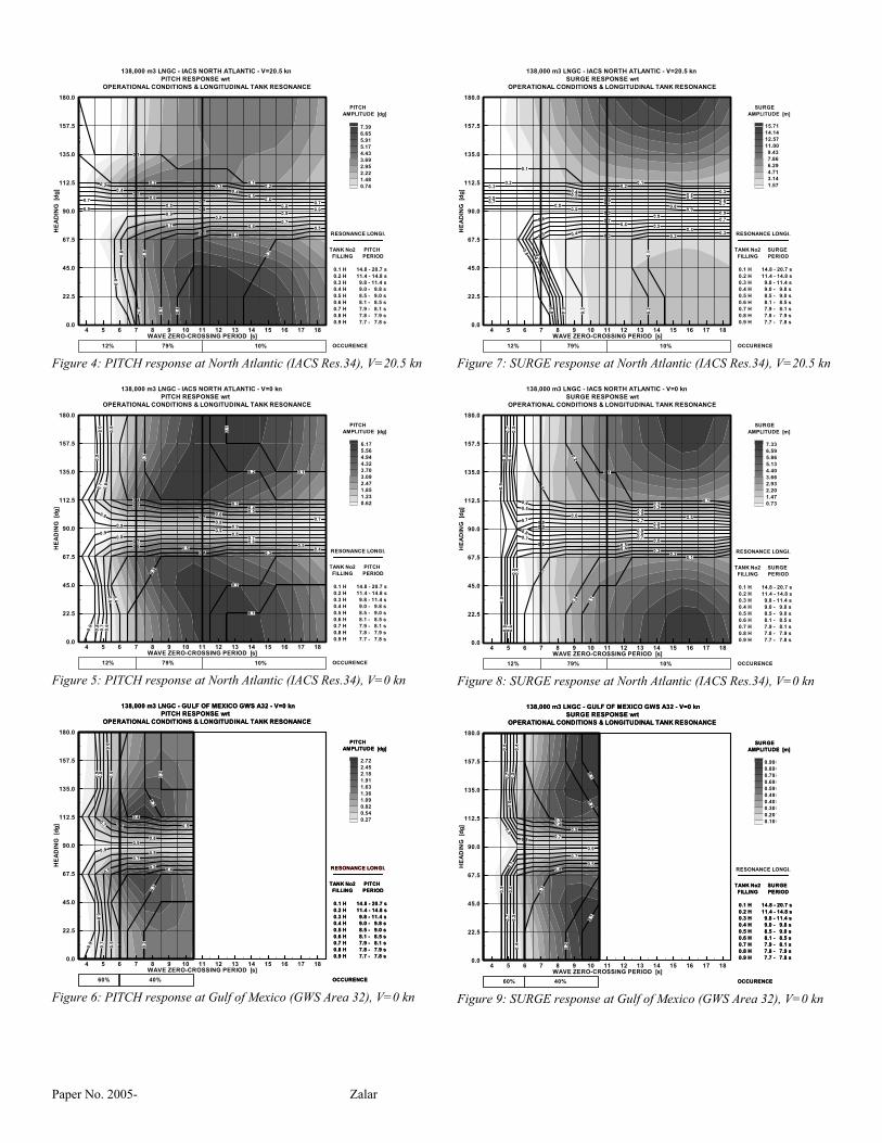
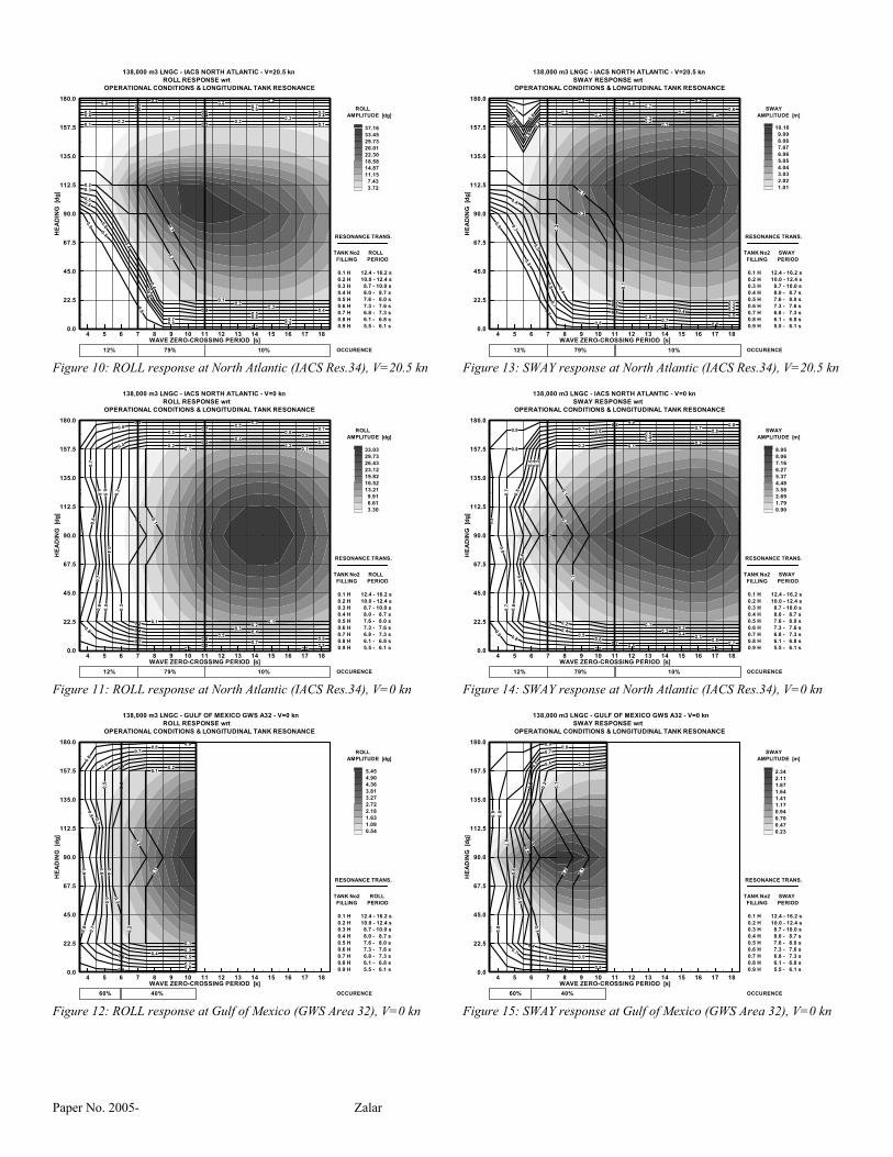
Based on the set of hydrodynamic computation results for characteristic intermediate loading conditions and tank resonance analysis for all partial fillings, the overall envelope of ship response is derived for two analyzed ship speeds (design speed and zero-speed) and nine headings from head to following sea. For the current example, environmental conditions correspond to the assumed scenario of ship service in North Atlantic and at a terminal in the Gulf of Mexico, with general wave data provided by IACS (IACS 2000) and Global Wave Statistics (BMT 1986). Iso-curves (zero-crossing periods) and iso-surfaces (amplitudes) of vessel response are presented in Figures 4 to 15, for both the longitudinal and transverse directions. DISSCUSSION The vessel responses utilized for determination of sloshing excitation are given in terms of maximum amplitudes at the significant 1/10th level and zero crossing periods, according to Bureau Veritas specification (BV Preliminary Guidelines, 2005). Four motion degrees of freedom are examined: Pitch, Surge, Roll and Sway; each of them might be dominant to excite the tank liquid in the longitudinal or transverse directions. The variables assigned to the diagram axes are wave headings (zero being head sea as per the common convention) and wave zero-crossing periods. Resonance Condition The vessel response relevant for the resonance condition is the vessel zero-crossing period, compared and associated with the tank natural period for each individual partial filling. These can be presented in the form of iso-curves of vessel response period plotted with contour levels corresponding to tank natural period for partial fillings from 10 percent to 90 percent of tank height. Combinations of ship speed, relative wave heading and wave period can be identified from the resonance maps to avoid a resonance condition regardless of the actual wave height and for any partial filling that might occur during a transient phase of LNG transfer. Maximum Motion Condition Maximum motion can affect any tank filling at certain combinations of wave significant height and wave zero-crossing period. These can be presented in the form of iso-surfaces, where ship response amplitudes are plotted at several contour levels, from zero to the maximum amplitude value. The combination of ship speed, relative wave heading and wave period can be identified from the maximum motion map to
avoid excessive ship motion for any partial filling that might occur. In order to mitigate severe sloshing effects associated with resonance condition, the regions of pronounced maximum motion and resonance for particular fillings should not coincide. CONCLUSION Operability guidance presented in this paper is devoted to the safe operation of conventional, not-reinforced vessels, aimed to: o Assess full flexibility when operating a vessel with
intermediate fillings during a transient phase of LNG transfer,
o Provide operational criteria to avoid undesired sloshing effects.
Resonance analyses provide information how to operate a vessel out of resonance in relation to any particular partial filling that can occur and regardless of the actual wave height. The maximum motion analyses provide information on the magnitude of the ship response that may affect any partial filling condition. In order to mitigate severe sloshing effects associated with a resonance condition, the regions of pronounced maximum motion and resonance for particular fillings should not coincide. Particular attention should be given to the description of environmental data for the operation at each specific site. As demonstrated by examples of response cartography, important regions of ship response can be omitted due to the insufficient data on the range of wave periods. In addition, more detailed data on the wave character, such as long-crested or swell seas, are indispensable to properly model the wave energy spectrum. Operability recommendations should be further refined by incorporation of the results of complementary analysis, such as: o Ship motion studies for additional ranges of ship speeds to
demonstrate overall ship performance for the most likely navigation conditions in service.
o Tank liquid motion study to define the upper bound of sea-states that allows safe vessel operation.
REFERENCES ABRAMSON, H.N. “The Dynamic Behavior of Liquids in
Moving Containers.” NASA SP-106, 1966 BRITISH MARINE TECHNOLOGY. “Global Wave
Statistics.” London: Unwin Brothers Limited, 1986 BUREAU VERITAS. “Sloshing on Board Ship - Partial filling
Study.” Guidance Note N.I. 171 ARD.1, 1984 BUREAU VERITAS. “Sloshing Assessment – Partial Fillings
of Membrane Type LNG Carriers and Offshore Floating Units.” Preliminary Guidelines, Rev. 1, 2005
Paper No. 2005- Zalar
Paper No. 2005- Zalar
BUREAU VERITAS. " HydroSTAR For Expert (v3.01) - A Reference Guide and Tutorial For Naval & Offshore Hydrodynamic Applications", 2004
CHEN, X.B. “Hydrodynamics in Offshore and Naval Applications.” 6th International Conference on Hydrodynamics, Perth, Australia, 2004
FALTINSEN, O.M., OLSEN H.A., ABRAMSON H.N. and BASS R.L. “Liquid Slosh in LNG Carriers.” 10th Symposium on Naval Hydrodynamics, Boston, USA, 1974
IACS, Rec.34. “Standard Wave Data for Direct Wave Load Analysis”, IACS Blue Book, Rev.1, 2000
MALENICA, Š., ZALAR, M. and CHEN, X.B. “Dynamic coupling of seakeeping and sloshing.” 13th ISOPE, Honolulu, USA, 2003
OCHI, M.K. “Wave Statistics for the Design of Ships and Ocean Structures.” SNAME Transactions, Vol. 86, 47-76, 1978,
SPITTAEL, L., ZALAR, M., LASPALLES, P. and BROSSET, L. “Methodology for Liquid Motion Analysis.” 19th GASTECH, Houston, USA, 2000
ZALAR, M., CAMBOS, P., BESSE, P., LE GALLO, B. and MRAVAK, Z. “Partial Fillings of Membrane Type LNG Carriers.” 21st GASTECH, Bilbao, Spain, 2005