structural optimization of a 220 000 m³ lng carrier - … lng opt_compit...structural optimization...
TRANSCRIPT
1
Structural Optimization of a 220 000 m³ LNG Carrier
Catalin Toderan, ANAST-ULG, Belgium, [email protected] J-L Guillaume-Combecave, Akeryards, France, [email protected]
Michel Boukaert, EXMAR, Belgium, [email protected] André Hage, DN&T, Belgium, [email protected]
Olivier Cartier, Bureau Veritas, France, [email protected] Jean-David Caprace, ANAST-ULG, Belgium, [email protected] Amirouche Amrane, ANAST-ULG, Belgium, [email protected]
Adrian Constantinescu, ANAST-ULG, Belgium, [email protected] Eugen Pircalabu, ANAST-ULG, Belgium, [email protected]
Philippe Rigo, ANAST-ULG, Belgium, [email protected] Abstract This paper relates to the development of a new concept of 220.000 m³ LNG designed by AKERYARDS France. This work is performed in the framework of FP6 IMPROVE project. The first phase of the activity related to the identification of stakeholder’s requirements and the definition of key performance indicators. In parallel, several calculations have been performed to test the existing tools and to evaluate the potential gain at the concept design. These activities, associated with the definition of a 220000 m³ QuatarFlex prototype, including the aspects related to the naval architecture and general arrangement, have been re-grouped in the so-called “first design loop”. The second phase concerns the development of new modules to be integrated in the optimization tools in order to satisfy the requirements defined in the first phase. The final phase will be the application of the new (improved) optimization tools for the final LNG product. We highlight that the main target will be the multi-objective structural optimization of the prototype defined by “the first design loop”. However, some feed-back concerning the naval architecture point of view could be expected in this phase. The aim of the paper is to present the results of the first phase, as well as an overview of the analyses carried out during the “first design loop”. Details about the different methodologies proposed for the second phase of the development are given. 1. Introduction The development of a new LNG concept is one of the targets of the FP6 IMPROVE project (Rigo et al., 2008). Obviously, the improved LNG product should satisfy the requirements from different stakeholders involved in LNG market (shipyards and ship-owners / operators) and to take into account the needs expressed by the design offices. In the same time, it is very important to assess the performance of this development, so to quantify the improvement (gain). A general overview of the IMPROVE framework, describing the different phases of the project and the choice of different strategies for the development, is given in Rigo et al. (2008). We highlight the fact that the major part of IMPROVE activity relates to the structural optimization and for this reason all the investigations and analysis presented here are oriented to the structural design. 2. Shipyard and ship-owner requirements for a new generation of LNG carriers One of the most important phase of IMPROVE activity was to identify, to investigate and to select shipyards and ship-owners requirements related to LNG product. The main partners involved on this task, AKERYARDS France (shipyard point of view) and EXMAR (ship-owner point of view), formulated an exhaustive list of requirements reviewed, commented and clarified by ANAST and DN&T (design office point of view).
2
The main challenge of this task was the “translate” stakeholder’s requirements into design criteria, so to identify the components of the design problem. These components have been used to set-up a complete roadmap for the LNG structural optimization problem. Recently AKERYARDS France designed and built several LNG carriers having the capacity between MedMax (74 000 m³) and WordWide (154 000 m³). In IMPROVE framework, they required to study the design of a QuatarFLEX (220 000 m³). This type is built nowadays only by asian shipyards. As a reference design of such a ship was not available at AKERYARDS, the shipyard proposed to perform a “first design loop” in the first phase of the project in order to design a QuatarFLEX prototype. This “first design loop” was a good opportunity for ANAST and DN&T to test the available tools (LBR5, VERISTAR, NAPA Steel, SAMCEF) and even to perform some concept optimizations using LBR5. The main interest of AKERYARDS was to reduce the construction cost balancing material and labor cost. The shipyard also presented a list of technological constraints related to production capabilities at Saint Nazaire. The main requirement from the ship-owner EXMAR was to avoid all structural problems in the cargo holds (tanks) and cofferdams. Any problem in these areas entails expensive repair works. Fatigue of cargo holds (tanks) and cofferdams and sloshing are the two critical issues and must be investigated to assess the structural strength. EXMAR feature also some innovative developments as “Ship to ship transfer” or “regasification ship – REGAS”. As these capabilities require a different design approach which is not yet covered by classification society’s rules, it was decided to consider them as secondary requirements to be taken into account in function of the remaining resources of the project. The complete list of shipyard and ship-owner requirements and the identification of design problem components are given at the Table 1 and Table 2 (See also Table 1 in Rigo and al. 2008). 3. QuatarFLEX prototype definition – the “first design loop” As mentioned above, the prototype has been designed by AKERYARDS during the “first design loop” phase. All the aspects related to the general arrangement, propulsion, hull shape and also the initial dimensioning of the structure have been investigated. The main characteristics of this prototype are given at the Table 3. The “first design loop” also included several tasks related to the optimization, as follows:
- ANAST performed a fast scantling optimization of the prototype with minimal construction cost objective function using the home-developed tool LBR5 (2008). The goal of this task was to check the behaviour of a gradient-based optimizer for the LNG model, to identify the major problems and to perform a first evaluation of construction cost.
- DN&T built a NAPA Steel model for the cargo part of the prototype; the aim was to test the potential of such a model for integration and to provide a CAD base for future applications related to FEA or detailed cost assessment.
- ANAST built a VERISTAR-Hull three tanks model for the cargo part of the LNG; the licences of this software and the technical assistance have been provided by Bureau Veritas. This model was used for several FEA calculation on coarse mesh (orthotropic elements) and fine mesh (generic shell and beam elements).
3
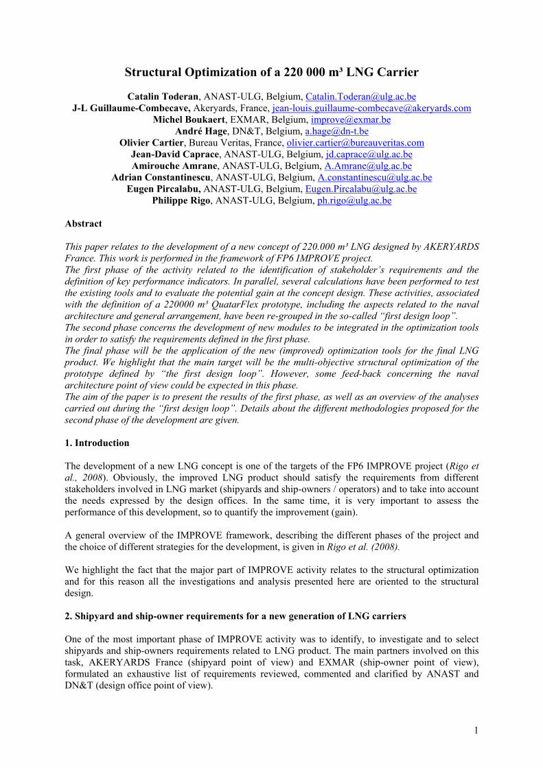
Table 1: Shipyard (AKERYARDS) requirements for LNG product
SHIP DESIGN REQUIREMENTS (AKERYARDS)
Reduction of production cost – balancing material and labor cost: this reduction concerns the optimization of structural scantlings but also a review of production processes, block splitting sequence, usage of available space using simulation techniques. Reduce draft in ballast condition (as this can lead to lower exploitation costs and cheaper ships): the main goal is to design a “dry” (not used for ballast) double-bottom, cheaper to build and to maintain. Reduce the hydrodynamic resistance (or minimum required power for propulsion) Development of “regasification” type ship (REGAS): REGAS ship is able to be unloaded through pipe connection after having changed on board the liquid cargo to natural gas. (this goal is required by the operator EXMAR but it is also specified by AKERYARDS)
Des
ign
goal
s
“Ship to ship transfer” capability: able to perform loading / unloading from a ship to another. (this goal is required by the operator EXMAR but it is also specified by AKERYARDS) Satisfy Bureau Veritas and GTT requirements.
The vessel should be able to sail with a cargo volume going from 0 % to 98.5 % of the total cargo volume, with all tanks loaded within the filling limits imposed by GTT. Constraints related to the production process - block size, standard plates dimension, workshops, portal crane and dry dock capacities.
Investigation on double-bottom height: if more than 3m (standard plate) additional welding is required. The increase of construction cost should be acceptable. Assessment of fatigue at early stage design is required. D
esig
n co
nstra
ints
STRUCTURAL DESIGN REQUIREMENTS (AKERYARDS)
Structural scantlings (stiffened plates, girders, frames,..) Local geometry for the fatigue sensitive parts.
Des
ign
para
met
ers
Double-bottom height – for a special investigation balancing the structural cost and the structural rigidity. Maximize fatigue life (scantlings, local geometry) Minimize the cost of the structure (scantlings, local geometry) Minimize the straightening work cost (scantlings) Minimize the additional construction cost due to a double-bottom height higher than 3 m (scantlings, double-bottom height)
Des
ign
goal
s
Maximize structural safety (scantlings, local geometry)
Satisfy Bureau Veritas Rules and GTT Requirements Design the hull structure to have the fatigue life >= 40 years, based on the classification society’s most severe requirements Satisfy production constraints related to the dimension of structural elements. (minimal plate thickness and dimensions, standardized profiles, maximal dimensions of T-synthetic) Reduce stress concentrations (e.g. at the feet of the cofferdam by including slope) regarding fatigue life. D
esig
n co
nstra
ints
Consider 120 N/mm² as allowable stress for the plate in contact with cargo. Design of the cofferdam inserted between fuel tank and hull plate.
Not
es &
ot
her
4
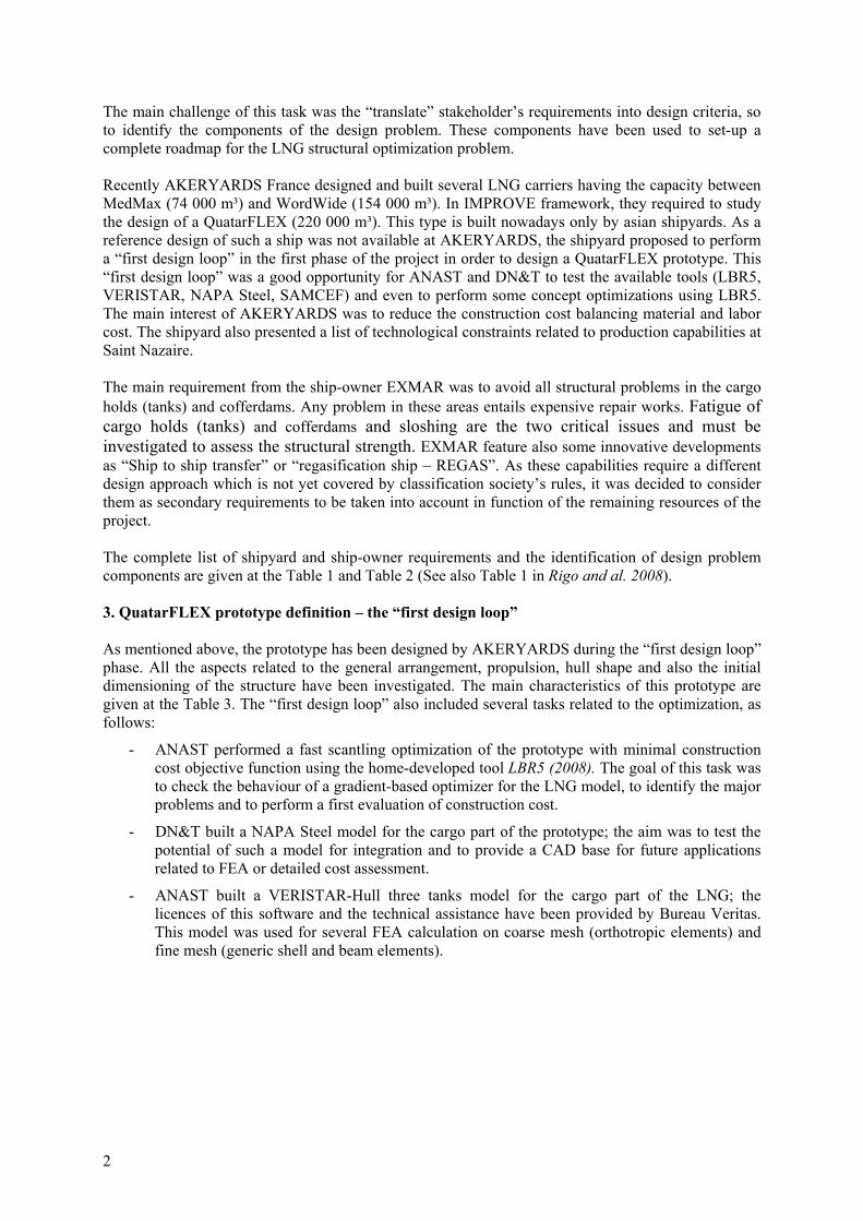
Table 2: Ship-owner (EXMAR) requirements for LNG product
SHIP DESIGN REQUIREMENTS (EXMAR)
Minimize hydrodynamic resistance / minimum required power for propulsion by optimizing the hull lines (Target gain = 3 %)
This is a relevant design goal for the Owner, however it is not possible to declare any minimum or target gain for this item. It should be confirmed by AKER how much gain they can get by optimizing the hull lines. Maximize propulsion efficiency. Reduce draft in ballast condition (as this can lead to lower exploitation costs and cheaper ships). Enable “Ship to ship transfer” capabilities. secondary requirement D
esig
n go
als
Develop “Regasification type ship - REGAS” capabilities. secondary requirement
Ship’s scantlings should be compatible with the Owner supplied dimensions of terminals
The vessel should be able to sail with the cargo volume going from 0 % to 98.5 % of the total cargo volume, with all tanks loaded within the filling limits imposed by GTT. The vessel should comply with Rules and Regulations for the following relevant loading conditions (filling) requested by the Owner: Ballast, max. bunkers, departure and arrival Homogeneously loaded at the designed draft (Specific Gravity = 0.47 ton/m³), max. bunkers,
departure and arrival Homogeneously loaded at the scantling draft (Specific Gravity = 0.50 ton/m³), max. bunkers,
departure and arrival One tank empty (No. 1, 2, 3, 4 or 5 cargo tank each, Specific Gravity = 0.47 ton/m³ and 0.50
ton/m³), departure and arrival Any two tanks filling condition (Specific Gravity = 0.47 ton/m³), departure and arrival Any one tank filling condition (Specific Gravity = 0.47 ton/m³), departure and arrival Dry docking, arrival Offshore unloading condition: homogenously cargo loaded (98 % filling, Specific Gravity =
0.47 ton/m³) with the bunkers of departure condition and 5 % of water in all water ballast tanks with actual free surface effects
Gain in hydrodynamic resistance (or in minimum required power for propulsion) ≥ 2%
Des
ign
cons
train
ts
The amount of fuel oil on board should be sufficient to obtain the cruising range > 10,000 NM on the basis of the following conditions: Service speed of 19.5 knots at the design draft Main propulsion machinery running at rating Fuel oil with specific gravity of 0.990 ton/m³ and a higher calorific value of 10,280 kcal/kg Fuel oil tanks 98% full, 2% un-pumpable with a reserve for 5 days
Insert the cofferdam between the fuel tank and side shell.
Not
es &
ot
her
5
STRUCTURAL DESIGN REQUIREMENTS
(EXMAR) Structural scantlings (stiffened plates, girders, frames, etc.) Prefer the usage of the following profile characteristics:
o As much as possible symmetrical profiles to avoid secondary bending stresses o The profiles should be optimized regarding the steel weight o The profiles should allow a good adhesion of the paint at the edges D
esig
n pa
ram
eter
s
Definition of local geometry for the fatigue sensitive parts.
Maximize the fatigue life (The Owner requested fatigue life should be ensured).
Des
ign
goal
s
Satisfy BV Class (and other) Rules and Regulations. Design the hull structure to have the fatigue life ≥ 40 years, based on the classification society’s most severe requirements. To constrain the effect of the fatigue at the feet of the cofferdam, investigate longitudinal sloshing and cargo motion (in cargo tanks which are filled within the GTT filling criteria) during pitching. Reduce stress concentrations (e.g. at the feet of the cofferdam by including slope) relevant for the fatigue life.
Des
ign
cons
train
ts
Ensure the unlimited filling condition at zero speed and within a given wave spectrum (unlimited filling condition in navigation is of no interest). Establish the link between ship routes and fatigue damages. Sensitivity analysis is required.
Not
es
&
othe
r
Table 3: Main characteristics of 220 000 m³ prototype
Length overall 317.00 m Length between perpendiculars 303.00 m Breadth moulded 50.00 m Depth (Main deck) 27.40 m Design draft (LNG = 0.47 t/m3) 12.50 m Qatar draft (LNG = 0.44 t/m3), abt 12.00 m Scantling draft 13.20 m Air draft 55.00 m Gross Tonnage, abt 145,000 (UMS) Net Tonnage 43,500 (UMS) Cargo capacity (100 % at – 163°C) Abt. 220,000 m3 Containment system GTT membrane CS1 (NO96 system
optionally) Boil-Off-Rate, abt 0.135 % per day Number of cargo tanks Five (5) Service Speed (at 85 % MCR, incl. 20 % SM) 20.0 knots Range Above 10,000 nautical miles Propulsive Power (Electric) 36,000 kW Propellers Twin-Screw, fixed-pitch propellers, abt.
8.00 m each (Usage of PODS optionally)
Installed Power (Dual-Fuel Gensets) 51,300 kW 3 x 16V50DF + 1 x 6L50DF (Based on Wärtsila engines)
Consumption (Fuel gas) Abt. 165.4 t/day Consumption (MDO pilot fuel) 1.8 t/day Complement 40 persons Classification Bureau Veritas
6
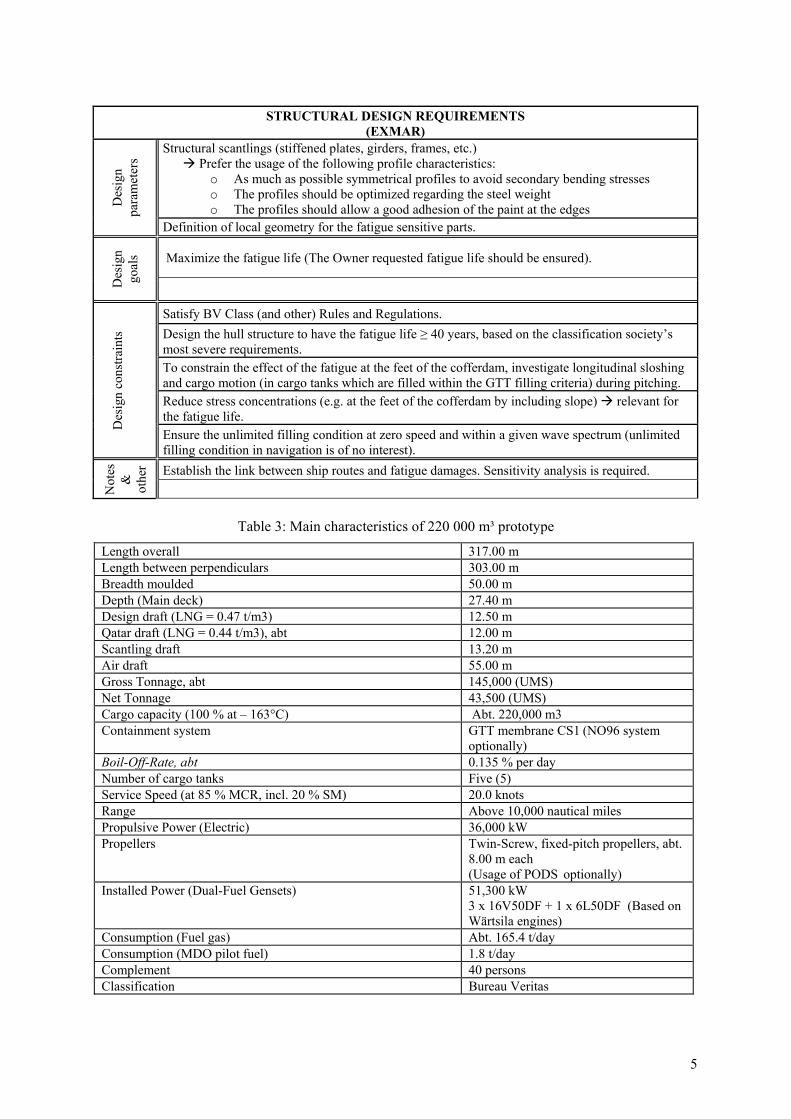
4. Structural optimization of the LNG prototype 4.1 Fast LBR5 optimization with minimal construction cost The goal of this optimization is to investigate the use of LBR5 optimization tool on the LNG product proposed by AKERYARDS and to identify the needs of improvement. Both structural analysis and scantlings optimization have been investigated. The initial scantling of the structural model has been defined by AKERYARDS using MARS software and respecting BV rules. The MARS model was imported in LBR5 via an automatic transfer file created through MARS user interface (web site: http://www.veristar.com/wps/portal/!ut/p/_s.7_0_A/7_0_CG8). This file contains the geometry and the scantlings but also the loadings. Additional nodes have been used in MARS in order to respect the detailed scantlings and to avoid some average values (stiffeners scantlings). As in MARS, due to the symmetry, only a half section has been modelled. The model obtained is presented in Figure 1.
Figure 1: LBR5 model for one tank (2.5 D and 2D)
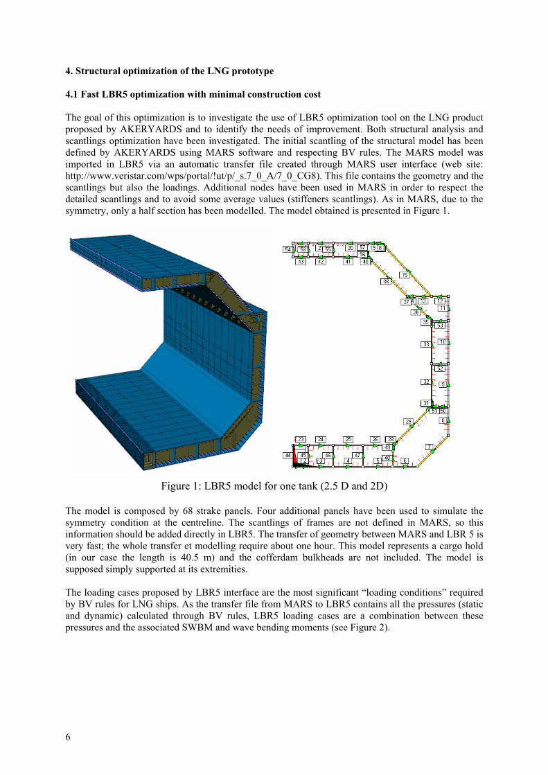
The model is composed by 68 strake panels. Four additional panels have been used to simulate the symmetry condition at the centreline. The scantlings of frames are not defined in MARS, so this information should be added directly in LBR5. The transfer of geometry between MARS and LBR 5 is very fast; the whole transfer et modelling require about one hour. This model represents a cargo hold (in our case the length is 40.5 m) and the cofferdam bulkheads are not included. The model is supposed simply supported at its extremities. The loading cases proposed by LBR5 interface are the most significant “loading conditions” required by BV rules for LNG ships. As the transfer file from MARS to LBR5 contains all the pressures (static and dynamic) calculated through BV rules, LBR5 loading cases are a combination between these pressures and the associated SWBM and wave bending moments (see Figure 2).
7
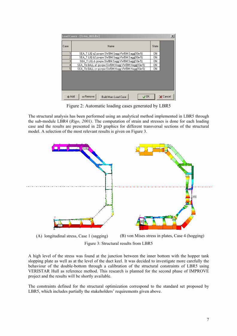
Figure 2: Automatic loading cases generated by LBR5 The structural analysis has been performed using an analytical method implemented in LBR5 through the sub-module LBR4 (Rigo, 2001). The computation of strain and stresses is done for each loading case and the results are presented in 2D graphics for different transversal sections of the structural model. A selection of the most relevant results is given on Figure 3.
(A) longitudinal stress, Case 1 (sagging) (B) von Mises stress in plates, Case 4 (hogging)
Figure 3: Structural results from LBR5
A high level of the stress was found at the junction between the inner bottom with the hopper tank slopping plate as well as at the level of the duct keel. It was decided to investigate more carefully the behaviour of the double-bottom through a calibration of the structural constraints of LBR5 using VERISTAR Hull as reference method. This research is planned for the second phase of IMPROVE project and the results will be shortly available. The constraints defined for the structural optimization correspond to the standard set proposed by LBR5, which includes partially the stakeholders’ requirements given above.
8
The set of these constraints covers: - plate, stiffeners and frames yielding - stiffened plate ultimate strength (Paik model) - plate buckling (Hughes model) - geometrical constraints - equality constraints (for frame spacing, for double-bottom stiffener spacing) - technical bounds (as defined by AKERYARDS)
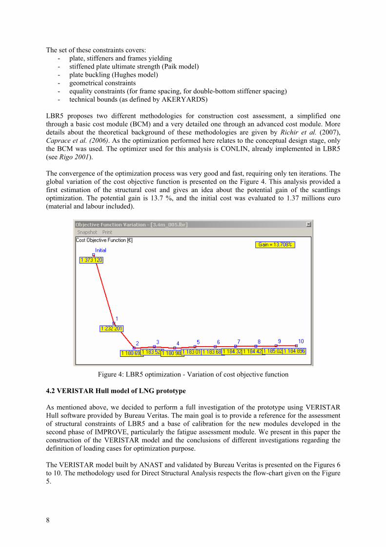
LBR5 proposes two different methodologies for construction cost assessment, a simplified one through a basic cost module (BCM) and a very detailed one through an advanced cost module. More details about the theoretical background of these methodologies are given by Richir et al. (2007), Caprace et al. (2006). As the optimization performed here relates to the conceptual design stage, only the BCM was used. The optimizer used for this analysis is CONLIN, already implemented in LBR5 (see Rigo 2001). The convergence of the optimization process was very good and fast, requiring only ten iterations. The global variation of the cost objective function is presented on the Figure 4. This analysis provided a first estimation of the structural cost and gives an idea about the potential gain of the scantlings optimization. The potential gain is 13.7 %, and the initial cost was evaluated to 1.37 millions euro (material and labour included).
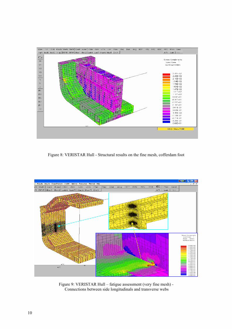
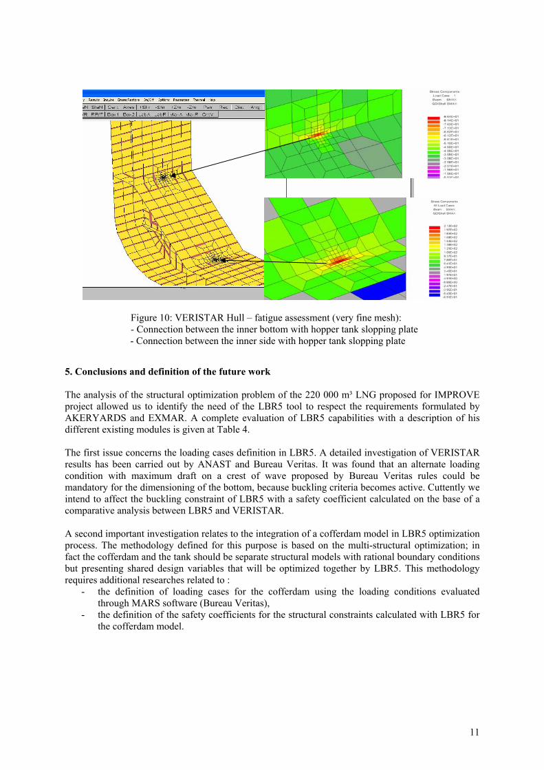
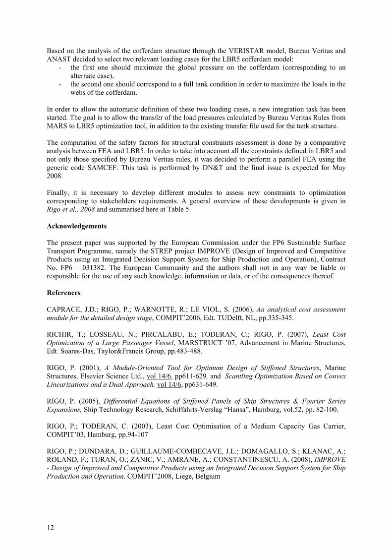
Figure 4: LBR5 optimization - Variation of cost objective function 4.2 VERISTAR Hull model of LNG prototype As mentioned above, we decided to perform a full investigation of the prototype using VERISTAR Hull software provided by Bureau Veritas. The main goal is to provide a reference for the assessment of structural constraints of LBR5 and a base of calibration for the new modules developed in the second phase of IMPROVE, particularly the fatigue assessment module. We present in this paper the construction of the VERISTAR model and the conclusions of different investigations regarding the definition of loading cases for optimization purpose. The VERISTAR model built by ANAST and validated by Bureau Veritas is presented on the Figures 6 to 10. The methodology used for Direct Structural Analysis respects the flow-chart given on the Figure 5.
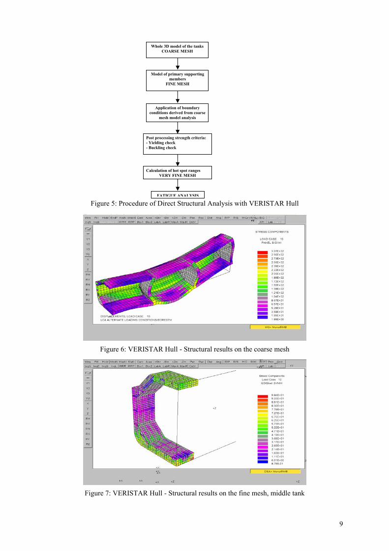
9
Figure 5: Procedure of Direct Structural Analysis with VERISTAR Hull
Figure 6: VERISTAR Hull - Structural results on the coarse mesh
Figure 7: VERISTAR Hull - Structural results on the fine mesh, middle tank
Whole 3D model of the tanks COARSE MESH
Model of primary supporting members
FINE MESH
Post processing strength criteria: - Yielding check - Buckling check
Calculation of hot spot ranges VERY FINE MESH
Application of boundary conditions derived from coarse
mesh model analysis
FATIGUE ANALYSIS
10
Figure 8: VERISTAR Hull - Structural results on the fine mesh, cofferdam foot
Figure 9: VERISTAR Hull – fatigue assessment (very fine mesh) - Connections between side longitudinals and transverse webs
11
Figure 10: VERISTAR Hull – fatigue assessment (very fine mesh): - Connection between the inner bottom with hopper tank slopping plate
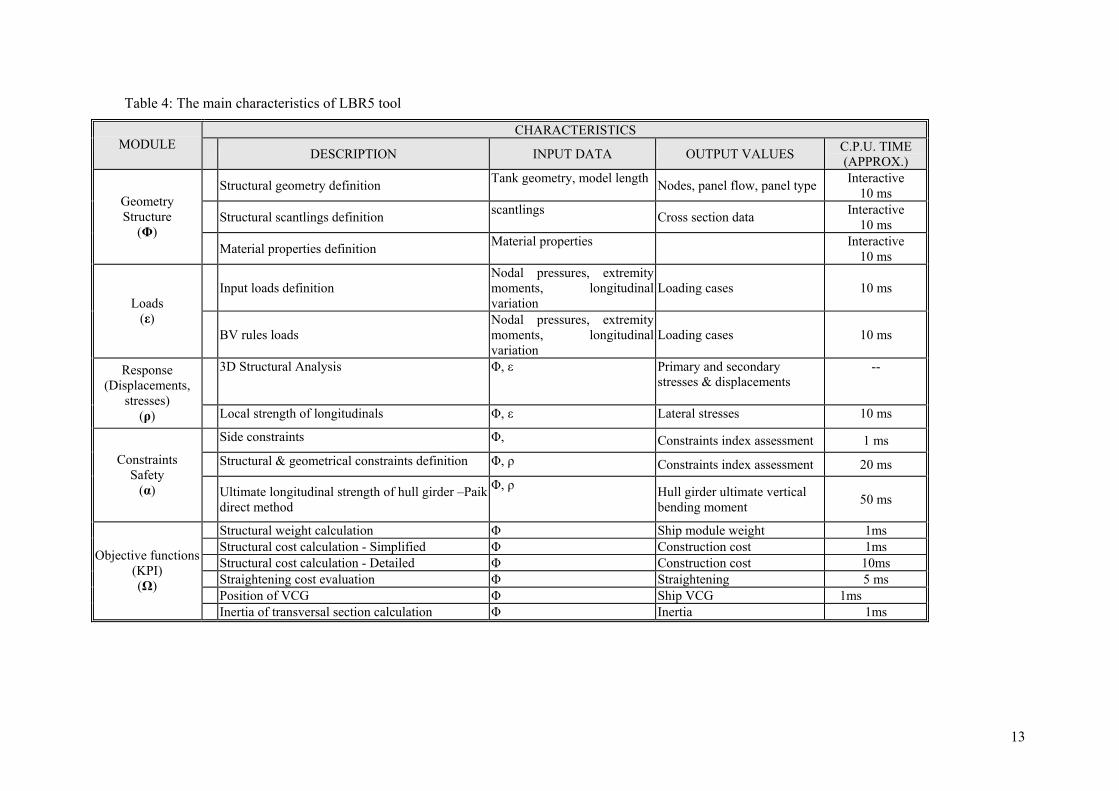
- Connection between the inner side with hopper tank slopping plate 5. Conclusions and definition of the future work The analysis of the structural optimization problem of the 220 000 m³ LNG proposed for IMPROVE project allowed us to identify the need of the LBR5 tool to respect the requirements formulated by AKERYARDS and EXMAR. A complete evaluation of LBR5 capabilities with a description of his different existing modules is given at Table 4. The first issue concerns the loading cases definition in LBR5. A detailed investigation of VERISTAR results has been carried out by ANAST and Bureau Veritas. It was found that an alternate loading condition with maximum draft on a crest of wave proposed by Bureau Veritas rules could be mandatory for the dimensioning of the bottom, because buckling criteria becomes active. Cuttently we intend to affect the buckling constraint of LBR5 with a safety coefficient calculated on the base of a comparative analysis between LBR5 and VERISTAR. A second important investigation relates to the integration of a cofferdam model in LBR5 optimization process. The methodology defined for this purpose is based on the multi-structural optimization; in fact the cofferdam and the tank should be separate structural models with rational boundary conditions but presenting shared design variables that will be optimized together by LBR5. This methodology requires additional researches related to :
- the definition of loading cases for the cofferdam using the loading conditions evaluated through MARS software (Bureau Veritas),
- the definition of the safety coefficients for the structural constraints calculated with LBR5 for the cofferdam model.
12
Based on the analysis of the cofferdam structure through the VERISTAR model, Bureau Veritas and ANAST decided to select two relevant loading cases for the LBR5 cofferdam model:
- the first one should maximize the global pressure on the cofferdam (corresponding to an alternate case),
- the second one should correspond to a full tank condition in order to maximize the loads in the webs of the cofferdam.
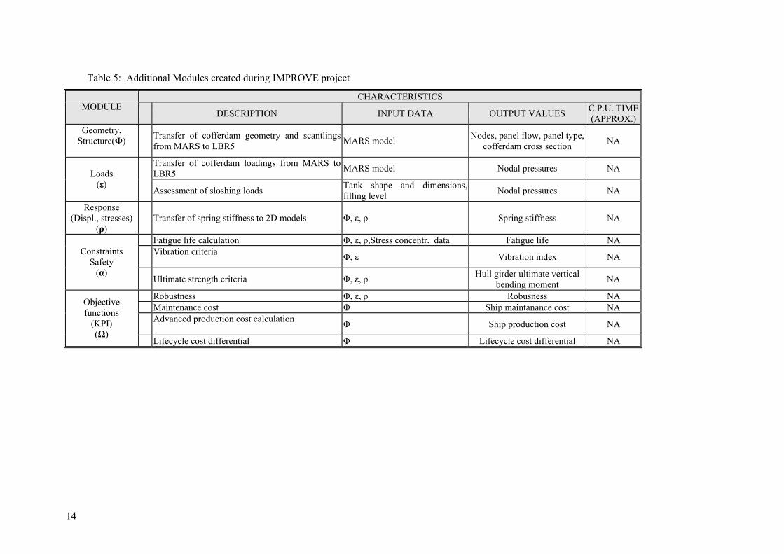
In order to allow the automatic definition of these two loading cases, a new integration task has been started. The goal is to allow the transfer of the load pressures calculated by Bureau Veritas Rules from MARS to LBR5 optimization tool, in addition to the existing transfer file used for the tank structure. The computation of the safety factors for structural constraints assessment is done by a comparative analysis between FEA and LBR5. In order to take into account all the constraints defined in LBR5 and not only those specified by Bureau Veritas rules, it was decided to perform a parallel FEA using the generic code SAMCEF. This task is performed by DN&T and the final issue is expected for May 2008. Finally, it is necessary to develop different modules to assess new constraints to optimization corresponding to stakeholders requirements. A general overview of these developments is given in Rigo et al., 2008 and summarised here at Table 5. Acknowledgements The present paper was supported by the European Commission under the FP6 Sustainable Surface Transport Programme, namely the STREP project IMPROVE (Design of Improved and Competitive Products using an Integrated Decision Support System for Ship Production and Operation), Contract No. FP6 – 031382. The European Community and the authors shall not in any way be liable or responsible for the use of any such knowledge, information or data, or of the consequences thereof. References CAPRACE, J.D.; RIGO, P.; WARNOTTE, R.; LE VIOL, S. (2006), An analytical cost assessment module for the detailed design stage, COMPIT’2006, Edt. TUDelft, NL, pp.335-345. RICHIR, T.; LOSSEAU, N.; PIRCALABU, E.; TODERAN, C.; RIGO, P. (2007), Least Cost Optimization of a Large Passenger Vessel, MARSTRUCT ’07, Advancement in Marine Structures, Edt. Soares-Das, Taylor&Francis Group, pp.483-488. RIGO, P. (2001), A Module-Oriented Tool for Optimum Design of Stiffened Structures, Marine Structures, Elsevier Science Ltd., vol 14/6, pp611-629, and Scantling Optimization Based on Convex Linearizations and a Dual Approach, vol 14/6, pp631-649. RIGO, P. (2005), Differential Equations of Stiffened Panels of Ship Structures & Fourier Series Expansions, Ship Technology Research, Schiffahrts-Verslag “Hansa”, Hamburg, vol.52, pp. 82-100. RIGO, P.; TODERAN, C. (2003), Least Cost Optimisation of a Medium Capacity Gas Carrier, COMPIT’03, Hamburg, pp.94-107 RIGO, P.; DUNDARA, D.; GUILLAUME-COMBECAVE, J.L.; DOMAGALLO, S.; KLANAC, A.; ROLAND, F.; TURAN, O.; ZANIC, V.; AMRANE, A.; CONSTANTINESCU, A. (2008), IMPROVE - Design of Improved and Competitive Products using an Integrated Decision Support System for Ship Production and Operation, COMPIT’2008, Liege, Belgium
13
Table 4: The main characteristics of LBR5 tool
CHARACTERISTICS MODULE
DESCRIPTION INPUT DATA OUTPUT VALUES C.P.U. TIME (APPROX.)
Structural geometry definition Tank geometry, model length Nodes, panel flow, panel type Interactive 10 ms
Structural scantlings definition scantlings Cross section data Interactive 10 ms
Geometry Structure
(Φ) Material properties definition Material properties Interactive
10 ms
Input loads definition Nodal pressures, extremity moments, longitudinal variation
Loading cases 10 ms Loads
(ε) BV rules loads
Nodal pressures, extremity moments, longitudinal variation
Loading cases 10 ms
3D Structural Analysis Φ, ε
Primary and secondary stresses & displacements
-- Response (Displacements,
stresses) (ρ) Local strength of longitudinals Φ, ε Lateral stresses 10 ms
Side constraints Φ, Constraints index assessment 1 ms
Structural & geometrical constraints definition Φ, ρ Constraints index assessment 20 ms Constraints Safety
(α) Ultimate longitudinal strength of hull girder –Paik
direct method
Φ, ρ Hull girder ultimate vertical bending moment 50 ms
Structural weight calculation Φ Ship module weight 1ms Structural cost calculation - Simplified Φ Construction cost 1ms Structural cost calculation - Detailed Φ Construction cost 10ms Straightening cost evaluation Φ Straightening 5 ms Position of VCG Φ Ship VCG 1ms
Objective functions(KPI) (Ω)
Inertia of transversal section calculation Φ Inertia 1ms
14
Table 5: Additional Modules created during IMPROVE project
CHARACTERISTICS MODULE
DESCRIPTION INPUT DATA OUTPUT VALUES C.P.U. TIME (APPROX.)
Geometry, Structure(Φ)
Transfer of cofferdam geometry and scantlings
from MARS to LBR5 MARS model Nodes, panel flow, panel type, cofferdam cross section NA
Transfer of cofferdam loadings from MARS to LBR5 MARS model Nodal pressures NA Loads
(ε) Assessment of sloshing loads Tank shape and dimensions,
filling level Nodal pressures NA
Response (Displ., stresses)
(ρ) Transfer of spring stiffness to 2D models Φ, ε, ρ Spring stiffness NA
Fatigue life calculation Φ, ε, ρ,Stress concentr. data Fatigue life NA
Vibration criteria Φ, ε Vibration index NA Constraints
Safety (α)
Ultimate strength criteria Φ, ε, ρ Hull girder ultimate vertical bending moment NA
Robustness Φ, ε, ρ Robusness NA Maintenance cost Φ Ship maintanance cost NA
Advanced production cost calculation Φ Ship production cost NA
Objective functions
(KPI) (Ω)
Lifecycle cost differential Φ Lifecycle cost differential NA