lng carrier master’s marine services manual -...
TRANSCRIPT

LNG Carrier Masters’s Marine Services Manual
Version Feb 2017
This document is proprietary to Gate terminal BV and shall not be reproduced in whole or part by any means without prior approval in writing from Gate’
1
LNG Carrier Master’s Marine Services Manual

LNG Carrier Masters’s Marine Services Manual
Version Feb 2017
This document is proprietary to Gate terminal BV and shall not be reproduced in whole or part by any means without prior approval in writing from Gate’
2
Emergency Contacts
Contact External Telephone Number / VHF Internal
Gate LNG Main Office +31 (0)181 799 000 1000
Gate LNG Emergency – Main Gate +31 (0)181 799 001 1001
Gate LNG Security – Main Gate +31 (0)181 799 035 1035
Gate LNG Control Room +31 (0) 181 799 020 / VHF 9 1020
Gate LNG SHEQ Advisor +31 (0)181 799 024 1024
Mobile +31 (0)6 1243 5062
Gate LNG PFSO = Marine Supervisor +31 (0)181 799 023 1023
Mobile +31 (0)6 1277 5202
email [email protected]
Shipping mailbox email [email protected]
Gate LNG Shift supervisor Operations +31 (0)181 799 022 1022
Mobile +31 (0)6 2352 7519
Duty Manager Mobile +31 (0)6 2007 1058
LNGC on Jetty 1 2010
LNGC on Jetty 2 2011
Immigration +31 (0)88 964 27 20
email [email protected]
Dirkzwager +31 (0)10 414 42 22
Port Security Officer (PFO) +31 (0)10 252 18 27
Port – Harbour Coordination Center (HCC) +31 (0)10 252 10 00/ VHF 14
HCC (Emergencies, ordering tugs, boatmen) VHF 11
HCC (listen out when alongside) VHF 19
Port – Vessel Traffic & Operations +31 (0)10 252 10 00 / VHF 19
Rotterdam – Rijnmond Seaport Police +31 (0)88 964 27 20
Rotterdam Police / Fire / Ambulance +31 (0)10 252 10 00 / VHF 11
DISCLAIMER:
For information purposes only, no right can be claimed, no responsibility for errors, subject to change without notice

LNG Carrier Masters’s Marine Services Manual
Version Feb 2017
This document is proprietary to Gate terminal BV and shall not be reproduced in whole or part by any means without prior approval in writing from Gate’
3
TABLE OF CONTENTS
1. INTRODUCTION .................................................................................................................. 6
1.1. Statement of purpose ......................................................................................................................................................................6
1.2. Scope of application .........................................................................................................................................................................6
1.3. References ..............................................................................................................................................................................................6
1.4. Definitions ..............................................................................................................................................................................................6
2. PORT OF ROTTERDAM ...................................................................................................... 9
2.1. Port Description ..................................................................................................................................................................................9
2.2. Port Location (PIG 7.3) .....................................................................................................................................................................9
2.3. Safety and Admission policy for LNG carriers ......................................................................................................................9
2.4. Port Metocean Environmental Data ....................................................................................................................................... 10
2.5. Port adverse weather conditions ............................................................................................................................................. 14
2.6. Port Tug Requirements / Towage ........................................................................................................................................... 14
2.7. Port Pilots / Pilotage – (PIG Section 11.3) ........................................................................................................................... 14
2.8. Port – Pre-Arrival and Departure Notifications ................................................................................................................. 14
2.9. Health (PIG 4.2) ................................................................................................................................................................................ 15
2.10. Immigration (PIG 4.3)..................................................................................................................................................................... 15
2.11. Customs (PIG 4.4) ............................................................................................................................................................................ 15
2.12. Documentation Required by PoR aboard LNGC (PIG Section 5) ............................................................................. 16
2.13. Reporting of Incidents (PIG 6) ................................................................................................................................................... 16
2.14. Emergency / Safety (PIG 9) ......................................................................................................................................................... 16
2.15. LNGC Maintenance and Repairs (PIG 14.3) ......................................................................................................................... 18
2.16. Port Security (PIG 10) .................................................................................................................................................................... 18
2.17. Stores and bunkering .................................................................................................................................................................... 18
2.18. Dangerous Goods (PIG 4.8) ........................................................................................................................................................ 19
2.19. Waste (PIG 4.9) ................................................................................................................................................................................. 19
2.20. Port Communication – VHF Channels: .................................................................................................................................. 19
2.21. Port LNGC Anchorage ................................................................................................................................................................... 19
2.22. Port Traffic Control – Vessel Traffic Service (VTS): .......................................................................................................... 20
2.23. Port / Local Time Zone (PIG 7.7) .............................................................................................................................................. 20
2.24. Flags and Signals ............................................................................................................................................................................. 20
3. TERMINAL INFORMATION ............................................................................................. 21

LNG Carrier Masters’s Marine Services Manual
Version Feb 2017
This document is proprietary to Gate terminal BV and shall not be reproduced in whole or part by any means without prior approval in writing from Gate’
4
3.1. Terminal Description ...................................................................................................................................................................... 21
3.2. Terminal Specification Overview .............................................................................................................................................. 21
3.3. Terminal & Berth Location .......................................................................................................................................................... 22
3.4. Terminal Policies .............................................................................................................................................................................. 23
3.5. Gate Pre-Arrival Procedures ....................................................................................................................................................... 29
3.6. Mooring / Berthing the LNGC ................................................................................................................................................... 31
3.7. Gangway Setting .............................................................................................................................................................................. 33
3.8. Ship / Shore Communications .................................................................................................................................................. 33
3.9. Ship / Shore Interface Meeting or Pre-Cargo Operation Meeting .......................................................................... 34
3.10. (Un)loading Preparation ............................................................................................................................................................... 34
3.11. (Un)loading Arms Connection ................................................................................................................................................... 35
3.12. Cargo Operation .............................................................................................................................................................................. 36
3.13. Unscheduled Cargo Operation Stoppage ............................................................................................................................ 36
3.14. (Un)loading Completion ............................................................................................................................................................... 37
3.15. Un-berthing ........................................................................................................................................................................................ 37
3.16. Gate Terminal Unloading Sequence of Events .................................................................................................................. 38
4. APPENDICES ..................................................................................................................... 39
4.1. Appendix A – Adverse Weather Policy: ................................................................................................................................ 39
4.2. Appendix B – Allowed Laytime & Allowed Unloading Time for LNGC’s .............................................................. 40
4.3. Appendix C – LNG Carrier Contact Information ............................................................................................................... 41
4.4. Appendix D1 – Safety and Admission Policy for LNG Carriers (Nijlhaven, Jetty 1 & 2)................................ 42
4.5. Appendix D2 – Safety and Admission Policy for LNG Carriers (Yukon haven, Jetty 3) ................................. 43
4.6. Appendix E – Forms Section ...................................................................................................................................................... 44
4.7. Appendix E1 – Work Authorization Form ............................................................................................................................ 44
4.8. Appendix E2 – Cargo Information Notice (also known as Notice of Departure) ............................................. 45
4.9. Appendix E3 – Notice of Arrival Information ..................................................................................................................... 46
4.10. Appendix E4 – Notice of Readiness ....................................................................................................................................... 47
4.11. Appendix E5 – Acceptance of the Notice of Readiness ............................................................................................... 48
4.12. Appendix E6 – Rejection of the Notice of Readiness .................................................................................................... 49
4.13. Appendix E7 – Terminal Status Notice.................................................................................................................................. 50
4.14. Appendix E8 – Notification of need to cancel subsequent Berthing Slot (due to LNG Carrier failing to
leave berth in a timely manner) ............................................................................................................................................................... 51
4.15. Appendix E9 – Gate Remedies for LNG Carrier Delays ................................................................................................. 52

LNG Carrier Masters’s Marine Services Manual
Version Feb 2017
This document is proprietary to Gate terminal BV and shall not be reproduced in whole or part by any means without prior approval in writing from Gate’
5
4.16. Appendix E10 – LNG Carrier / Gate Notice of Delay after Tendering the NOR ............................................... 53
4.17. Appendix E11 - Customer & Supplier info for cargoes ................................................................................................ 54
4.18. Appendix F – LNG Carrier / Gate Notice of Delay after Tendering the NOR .................................................... 55
4.19. Appendix G – Emergency Alarms ............................................................................................................................................ 56
4.20. Appendix H – Fire fighting Equipment / Capabilities .................................................................................................... 57
4.21. Appendix Ia – Jetty 1 & 2 Berth Arrangement Details ................................................................................................ 58
4.22. Appendix Ib – Jetty 3 Berth Arrangement Details ......................................................................................................... 59
4.23. Appendix I-1 – Jetty 1 & 2 – Platform Details .................................................................................................................. 61
4.24. Appendix I-2a – Jetty 1 & 2 Typical Mooring Plan ......................................................................................................... 62
4.25. Appendix I-2b Jetty 3 typical Mooring plan ....................................................................................................................... 63
4.26. Appendix I-3 – Jetty 1 & 2 Gangway Details ..................................................................................................................... 64
4.27. Appendix I-4a – Jetty 1 & 2 Manifold Flange Details (16 inch ANSI B16.5) ....................................................... 65
4.28. Appendix I-4b – Flange Details (10 inch ANSI B16.5) ................................................................................................... 67
4.29. Appendix I-5a – Jetty 1 & 2 (Un)loading Arm Details ................................................................................................... 68
4.30. Appendix I-5b Jetty 3 (Un)loading Arm Details ................................................................................................................ 69
4.31. Appendix I-6a – Jetty 1 & 2 Cargo Arm Operating Envelope ................................................................................... 70
4.32. Appendix I-6b – Jetty 3 Cargo Arm Operating Envelope ............................................................................................ 71
4.33. Appendix Ja – Ship / Shore Communication Details ..................................................................................................... 72
4.34. Appendix Jb Jetty 3 Ship / Shore Communication Details .......................................................................................... 73
4.35. Appendix K – Pre Cargo Operations Meeting Discussion Checklist ....................................................................... 74
4.36. Appendix K1 – Ship / Shore Safety Checklist .................................................................................................................... 75
4.37. Appendix K2 – Safety Declaration ........................................................................................................................................... 85
4.38. Appendix K3 – LNG (Un)loading Agreement ..................................................................................................................... 86
4.39. Appendix K4 – Declaration of Security ................................................................................................................................. 87
4.40. Appendix K5 – Statement of compliance Form ................................................................................................................ 89
4.41. Appendix K6 – ADN Checklist ................................................................................................................................................... 90
4.42. Appendix L – Post Cargo Operations Meeting Checklist & Issues Documentation ........................................ 96

LNG Carrier Masters’s Marine Services Manual
Version Feb 2017
This document is proprietary to Gate terminal BV and shall not be reproduced in whole or part by any means without prior approval in writing from Gate’
6
1. Introduction
1.1. Statement of purpose
This manual brings together relevant ship/shore and general Rotterdam Port information for Liquefied Natural Gas (LNG)
shipping activities at the Gate LNG Terminal
1.2. Scope of application
This document does not replace any of the formal Port or Terminal procedure, but merely highlights some key information.
For Marine issues the Master is advised to contact the Marine Supervisor at Gate Terminal.
The matters addressed in this manual are subject to contracts between Gate and its customers, Rotterdam Port regulations, and
regulations issued by international organizations. Masters using this manual are obliged to make sure they have the latest
versions of these regulations at their disposal and may not rely on this manual for the correct version of any applicable laws,
regulations or international standards or practices. Masters are also obliged to make sure they are in compliance with all health,
immigration, notification and customs requirements. The PIG Section 4 gives an overview of some of the requirements.
1.3. References
(a) ADN (European Agreement concerning the International Carriage of Dangerous Goods by Inland Waterways)
(b) Hydro meteo informatiebundel nr 4 hmb2012
(c) IMO “Ship/Shore Safety Check List”
(d) ISPS Compliance
(e) ISGINTT (International Safety Guide for Inland Navigation Tank-barges and Terminals)
(f) Port Information Guide Port of Rotterdam (PIG) – latest version
Port Information Guide
(g) 2010 Rotterdam Port management Bye-laws
Port Bye-laws 2010 (version January 2016)
(h) Safety and Admission policy for LNG Carriers Nijl haven (Jetty 1 & 2) and Yukon haven (Jetty 3)
(i) Safety assessment for the revised routing system in the approaches to Rotterdam II, MARIN , February 26, 2007
(j) SIGTTO “Liquefied Gas Handling Principles on Ships and Terminals”
(k) SIGTTO “Ship/shore Questionnaire for Compatibility Study of Liquefied Gas Ships with Loading / Unloading
jetties”, completed with Gate shore data
1.4. Definitions
I – Accord Européen relative au transport international des marchandises Dangereuses par voie de Navigation
Allowed Laytime – as defined in appendix B
Allowed Unloading Time – as defined in appendix B
ASD – Azimuth Stern Drive
BCM – Billion Cubic Meters
Cold Work – Repairs not involving and with no risk of fire or sparks.
EBB – Electronic Bulletin Board
ESD – Emergency Shutdown System
ETA – the estimated time of arrival of that LNG Carrier at the Pilot Boarding Station

LNG Carrier Masters’s Marine Services Manual
Version Feb 2017
This document is proprietary to Gate terminal BV and shall not be reproduced in whole or part by any means without prior approval in writing from Gate’
7
ETD – Estimated Time of Departure
Gate – Gate terminal B.V.
GMDSS – Global Maritime Distress Safety System
GGD – Municipal Health Services of Rotterdam
GMT – Greenwich Mean Time
HCC – Harbour Coordination Center
HMRC – Harbour Master’s Reporting Center
HoH – Hook of Holland
Hot Work – Work involving or may lead to a sources of ignition or temperatures sufficiently high to cause the
ignition of a flammable gas mixture. This includes but is not limited to work requiring the use of welding, burning or
soldering equipment, blow torches, power-driven tools, portable electrical equipment, sandblasting, or internal
combustion engine.
IMO – International Maritime Organization
IOPP – International Oil Pollution Prevention Certificate
ISGINTT – International Safety Guide for Inland Navigation Tank-barges and Terminals
ISGOTT – International Safety Guide for Oil Tankers and Terminals
ISPS – International Ship and Port Facility Security Code
LNGC – LNG carrier or ship capable of transporting LNG
MARPOL (Marine Pollution) – International Convention for the Prevention of Pollution From Ships
MOT – Maasvlakte Oil Terminal (adjacent to Gate LNG Terminal)
MMSM – this Master’s Marine Service Manual
mLC – Meters of Liquid Column
mT – Metric Tonnes
NA Peil – a bench mark in brass in the centre of Amsterdam, which is currently close to mean sea level at the Dutch
coast.
NoR – Notice of Readiness
N2 – Nitrogen Gas
OCIMF – Oil Companies International Marine Forum
Operator – Gate LNG Terminal
P & I – Protection and Indemnity Insurance
PBS – Pilot Boarding Station
PERC – Powered Emergency Release Coupler
PIG – Port Information Guide of the Port of Rotterdam
PoR – Port of Rotterdam
PPE – Personal Protection Equipment
Reasonable and Prudent Person – a person exercising the degree of skill, diligence, prudence and foresight which
would reasonably and ordinarily be exercised by an experienced person complying with all applicable laws and
international standards and engaged in the same type of undertaking under the same or similar circumstances and
conditions;
RSP – Reglement Scheepvaartpersoneel op de Rijn
Ship’s Representative – Ship’s Master or his appointed designee

LNG Carrier Masters’s Marine Services Manual
Version Feb 2017
This document is proprietary to Gate terminal BV and shall not be reproduced in whole or part by any means without prior approval in writing from Gate’
8
Ship’s Agent – Agency nominated by and acting on behalf of the vessel.
SIGTTO – Society of International Gas Tanker and Terminal Operators
SOLAS – Safety of Life at Sea Convention
SOPEP – Shipboard Oil Pollution Emergency Plan
Terminal – the Gate LNG terminal
Terminal’s Representative – Marine Supervisor or his representative
VT&O – Vessel Traffic & Operations
VTS – Vessel Traffic Service
LNG Carrier Masters’s Marine Services Manual
Version Feb 2017
This document is proprietary to Gate terminal BV and shall not be reproduced in whole or part by any means without prior approval in writing from Gate’
9
2. Port of Rotterdam
2.1. Port Description
The Port of Rotterdam is the main port of Europe and the fourth largest port in the world. The Port has calls from 35,000
seagoing vessels and 133,000 inland barges carrying over 430 million tons of cargo each year (2011). The Port operates 24
hours a day, 7 days a week and provides facilities for cargo handling, storage, and distribution. Nautical services for pilotage,
towage and linesmen are also readily available as are facilities for ship repair, maintenance and storage. The Port has 8 active
patrol boats and 2 on standby at all times. 8 Patrol boats have firefighting capabilities. For more information on the Port of
Rotterdam, visit the website:
http://www.portofrotterdam.com/EN/Pages/default.aspx
2.2. Port Location (PIG 7.3)
The Port of Rotterdam is situated at the entrance of the Nieuwe Waterweg River (Coordinates 52°00.0’N, 004°00.0’E) and
extends from its North Sea approach approximately 40 km further inland to the River Merwede (Rhine). Relevant nautical
charts and publications are listed in PIG Section 7.12
A description of the Port’s limits (boundaries) can be found in the PIG Section 7.4
2.3. Safety and Admission policy for LNG carriers
2.3.1 Nijl haven for Jetty 1 & 2 This document describes the nautical admission policy for LNG carriers (LNGC’s) in the Port of Rotterdam according to the
insights to date. See attached as Appendix D1.
In addition to these policies, the Port also:
Requires a LNGC to moor Bow in, Port side alongside heading NW (337o)
Have inspections on board moored vessels ensuring that vessels meet (inter)national safety, security and
environmental standards
Pilot boarding may be suspended when wave heights reach 2 to 2.7 m. (PIG 11.3)
Have a dedicated anchorage area for LNGC’s (see Section 2.10); and
All Masters are responsible for verifying and complying with the current Admission Policy for LNGC’s prior to arrival at the
Port.
2.3.2 Yukon haven for jetty 3 This document describes the nautical admission policy for LNG carriers (LNGC’s) in the Port of Rotterdam according to the
insights to date. See attached as Appendix D2.
In addition to these policies, the Port also:
In general requires a LNGC to moor Bow out, Port side alongside heading South (172o) Mooring bow in is allowed provided that a quick departure can be realized
Have inspections on board moored vessels ensuring that vessels meet (inter)national safety, security and
environmental standards
Pilot boarding may be suspended when wave heights reach 2 to 2.7 m. (PIG 11.3)
Have a dedicated anchorage area for LNGC’s (see Section 2.10); and
All Masters are responsible for verifying and complying with the current Admission Policy for LNGC’s prior to arrival at the
Port.

LNG Carrier Masters’s Marine Services Manual
Version Feb 2017
This document is proprietary to Gate terminal BV and shall not be reproduced in whole or part by any means without prior approval in writing from Gate’
10
2.4. Port Metocean Environmental Data
For general information regarding existing weather, tides, current, sea conditions, fog, ice, etc. the appropriate Traffic Center
sector can be contacted via VHF channel 11. Online hydrometeo information can be found at the website
http://www.portofrotterdam.com/en/Shipping/up-to-date/Hydrometeo/Pages/internet-amethyst.aspx
2.4.1 Wind – Measured at Gate terminal
Prevailing wind from the W-SW at Beaufort Force 3 – 5 (3.4 – 10.7 m/s)
Relative frequency of wind force greater than Beaufort Force 6 (13.8 m/s): 3%
Relative frequency of wind force greater than Beaufort Force 7 (17.1 m/s): 0%
Cumulative spread per month in terms of percentage
Cumulative spread per direction in terms of percentage
LNG Carrier Masters’s Marine Services Manual
Version Feb 2017
This document is proprietary to Gate terminal BV and shall not be reproduced in whole or part by any means without prior approval in writing from Gate’
11
2.4.2 Tides
Average water levels at Hook of Holland (Reference is NAP)
Low High
Dead tide -38 cm 75 cm
Mean tide -39 cm 126 cm
Spring tide -55 cm 153 cm
Extreme water levels measured:
High water: +288cm (28 Jan 1994)
Low water: -184cm (12 Mar 1996)
Additional general info can be found in PIG 7.17 and actual info via the following hyperlink:
http://live.getij.nl/getij_resultaat.cfm?location=BEERKNL
2.4.3 Currents
The currents in the Nijlhaven (along our jetties 1 & 2) are as follows
1.34 m/s = 2.6 kn (springtide flood)
0.49 m/s = 0.95 kn (springtide ebb)
The currents in the Yukonhaven (along our jetty 3) are negligible however passing vessels in the Yangtze channel might cause
surge depending on the passing distance, speed and draft.
General information regarding currents at the Port of Rotterdam is described in PIG section 7.17.
2.4.4 Water Density
General range near Europoort from 1025 kg/m3 at high water to 1012 kg/m3 at low water (depending on seasonal, tidal and
other influences). Additional information may be obtained via Harbour Master’s Office.
2.4.5 Water Depth
13.5 meters minimum alongside the Jetties 1 & 2 at LAT (=NAP -1.0)
10.0 meters alongside Jetty 3 at NAP

LNG Carrier Masters’s Marine Services Manual
Version Feb 2017
This document is proprietary to Gate terminal BV and shall not be reproduced in whole or part by any means without prior approval in writing from Gate’
12
2.4.6 Wave Data
Operational Conditions:
The frequency of exceedence of the different wave heights in the LNG channel for jetties 1 & 2 is calculated with a wave
model and the following table gives a result of these calculations:
Source: Wave Climate LNG terminal Maasvlakte, Sept 15, 2006
Exceedence probability swell jetty 1
(1990-2005)
Exceedence probability swell jetty 2
(1990-2005)
Swell P (all year) P (winter) P (summer P (all year) P (winter) P (summer
H=0.2 m 5.35% 8.5% 2.15% 4.22% 6.84% 1.57%
H=0.4 m 1.60% 2.64% 0.54% 1.15% 1.93% 0.37%
H=0.6 m 0.62% 1.09% 0.15% 0.41% 0.73% 0.08%
H=0.8 m 0.24% 0.44% 0.03% 0.13% 0.25% 0.01%
H=1.0 m 0.10% 0.18% 0.01% 0.04% 0.07% -
H=1.2 m 0.03% 0.06% - 0.02% 0.03% -
H=1.4 m 0.01% 0.03% - 0.00% 0.01% -
H=1.6 m 0.003% 0.006% - - - -
The wave direction of the swell entering the LNG channel varies between the main direction of the channel to approximately
25 degrees to the north
See also the PIG section 7.17 (Sea Conditions)
For jetty 3, which is situated at a sheltered location, swell is nil.
Only locally developed waves can be present. Maximum wave height is approx. 0.5m for the 7Bft. condition.

LNG Carrier Masters’s Marine Services Manual
Version Feb 2017
This document is proprietary to Gate terminal BV and shall not be reproduced in whole or part by any means without prior approval in writing from Gate’
13
2.4.7 General Weather
(1) Air and Water Temperatures
Air temperatures are relatively mild, due to the proximity of the Atlantic Ocean, with an absolute daily maximum
summer temperature reaching 35°C and a relatively mild winter climate with an absolute daily minimum temperature
reaching -15°C
Air temperature characteristics Water surface temperature characteristics
Average oC Average
minimum oC
Average
maximum oC Average oC
Average
minimum oC
Average
maximum oC
Jan 3.4 0.7 5.7 4.7 -0.1 7.2
Feb 3.4 0.3 6.3 4.7 -0.5 7.4
Mar 6.0 2.3 9.5 6.3 3.1 8.9
Apr 8.3 3.7 12.5 9.4 7.2 11.5
May 12.5 7.4 17.0 13.4 11.1 16.1
Jun 15.0 10.3 19.3 16.9 14.9 19.6
Jul 17.2 12.6 21.5 19.0 16.6 22.2
Aug 17.2 12.4 21.8 19.7 17.7 22.0
Sep 14.5 10.2 18.5 17.8 16.0 19.9
Oct 10.8 7.1 14.3 14.3 11.6 16.6
Nov 6.8 3.8 9.4 10.0 8.1 12.0
Dec 4.5 1.9 6.9 4.7 -0.1 7.2
(2) Atmospheric Pressure, Humidity, Rainfall, Wind
The following table provides a summary of the general weather conditions registered in Rotterdam over the period
1971–2000
Winter Spring Summer Autumn Year
Barometric pressure in HPa 1015.7 1014.8 1016.3 1015.1 1015.5
Relative humidity in % 88 81 80 86 84
Relative humidity in % at 12:00 UTC 85 71 68 78 76
Rainfall in mm 193.0 158.6 205.2 258.7 815.5
Days of Rainfall 59 56 53 61 229
Wind in m/s 5.7 5.0 4.2 4.8 4.9
Days wind >= 6 Bft (10.8-13.8 m/s) 23 15 6 15 59
Days wind >= 7 Bft (13.9-17.1 m/s) 7 3 0 4 14
Days wind >= 8 Bft (17.2-20.7 m/s) 1 0 - 0 1
(3) Visibility (measured at Hook of Holland)
Visibility is generally good. Rain and fog do from time to time reduce visibility and sometimes obstruct marine traffic
(when visibility drops below 1 km.
Frequency of visibility less than 2,000 m is 3.0% of the year
Frequency of visibility less than 1,500 m is 1.4% of the year
Frequency of visibility less than 500 m is 0.6% of the year
(4) Ice
Navigation from sea to Rotterdam is open at all times
LNG Carrier Masters’s Marine Services Manual
Version Feb 2017
This document is proprietary to Gate terminal BV and shall not be reproduced in whole or part by any means without prior approval in writing from Gate’
14
2.5. Port adverse weather conditions
The weather standards prescribed Nautical admission Policy which prevent an LNGC from proceeding to/from the Gate
Terminal are listed below.
Wind 6 on the Beaufort Scale (13.8 m/s)
Visibility at sea without a Deep Sea* pilot 2000 m for Jetty 1 & 2. For Jetty 3 no restriction
Visibility at sea with a Deep Sea* pilot 2000 m for Jetty 1 & 2. For Jetty 3 no restriction
Visibility in Port 2000 m for Jetty 1 & 2. For Jetty 3 no restriction
Deep Sea pilot will board at Brixham or Cherbourg, see PIG Section 11.3. These same criteria will also govern
whether the LNGC can leave the berth. The Harbour Master may also order changes as needed and the PIG could list
additional criteria.
2.6. Port Tug Requirements / Towage
Tugs will be required to satisfy the Port’s LNG admission Policy. (See paragraph 2.3 and appendix D1 & D2 of this
document). Towage is discussed in the PIG Section 11.4
Ordering a tug can be done through the LNGC’s agent, through the pilot or through the Port’s Vessel Traffic & Operations.
The VT&O contact information is:
Phone: +31 10 252 24 00
Email: [email protected]
VFH: Channel 19
Tugs must pick up the LNGC at the harbour entrance. Recommended speed for being tied to a tug is 4 to 6 knots depending on
the location of the tie. On VTS sector channel you can arrange a working channel with the tug, which will normally be VHF
channel 6 or 8. The pilots work on different channels with the tugs.
2.7. Port Pilots / Pilotage – (PIG Section 11.3)
Ordering a Pilot: When the ETA-48 hour notice is made; indicate the need for pilots.
According the Nautical Admission Policy for LNG carriers the reporting policy is uniform to deep draught vessels. Reporting
your ETA-48 hour notice needs to be done via your local agent. For additional information on ordering a pilot see Section 11.3
and Section 4.5 of the PIG.
Pilot boarding on arrival: Normal Pilot boarding by helicopter (preferred) or by tender. Helicopter pilot for small scale
vessels is not viable as no room for helicopter landing or winching area markings.
Regardless using Deep Sea Pilots, the Pilot for entering the harbour of Rotterdam will board the LNG Carrier just before the
Precautionary Area which is 7 nautical miles (roughly 13 kilometer) before the Maas Centre Buoy (see Map 1 at chapter 2.20
of this manual). If the LNG Carriers uses Deep Sea Pilotage, that Pilot comes on board at the Pilot Boarding Station at
Brixham or Cherbourg and takes over from there.
Normal Pilot boarding by tender may be suspended when wave heights reach 2 to 2.7 m.
LNGC can go at anchor or stem the current until safe conditions return.
Pilot Communication at ETA-3 hours is done via VHF channel 01 to “Sector Maasapproach” Communication with the Pilot
cutter, -tender or –swath can be accomplished on VHF Channel 02 to “Pilot Maas”. For more practical information on
Pilotage, please use the Port Information Guide (Section 11.3), all practical matters are described, including all communication
rules regarding pilotage.
2.8. Port – Pre-Arrival and Departure Notifications
Pre-arrival communications required by the Port of Rotterdam are discussed in PIG Section 3 and the Notices that are required
at each communiqué are discussed in PIG Section 4.5 and 4.6 respectively. The relevant Arrival and Departure Notice
Checklist can then be found in PIG Section 3.2 and PIG Section 3.3 respectively.

LNG Carrier Masters’s Marine Services Manual
Version Feb 2017
This document is proprietary to Gate terminal BV and shall not be reproduced in whole or part by any means without prior approval in writing from Gate’
15
2.9. Health (PIG 4.2)
Prior to arrival, the master has to complete and sign a Maritime Declaration of Health. The standard international form has to
be used and can be found at website:
http://www.portofrotterdam.com/en/Shipping/rules-regulations/port-health-authority/Pages/default.aspx
In case one of the form questions has been answered by “yes”, or in the case of other quarantine problems:
Advise the pilot, the ship agent and HCC
Mail or fax this form to [email protected] or fax this form to 010-252-1600
Keep the person responsible for medical care on board to answer any questions.
In all cases keep the Maritime Declaration of Health form stand-by.
In case of an epidemic threat the master can be requested to report the health situation on board to Vessel Traffic Operations or
VTS centre Hook of Holland.
2.10. Immigration (PIG 4.3)
Compliance with rules of the Rotterdam-Rijnmond Seaport Police (responsible for immigration) is compulsory at all times. In
the circumstances where the provisions of the Aliens Act (regulations pertaining to foreigners) fail to be complied with, the
persons to be held responsible may be reported. The use of standard IMO forms is mandatory.
Prior to Arrival the Master must:
forward a Crew and Passenger list (IMO FAL form no. 5 and 6) to your local agent and the contact specified below;
and
report the presence of any stowaways.
Prior Departure the Master must duly notify the head of the checkpoint through which his vessel will be passing, of his intent
to depart from the Netherlands. This notice must be made:
no more than six and no less than three hours prior to the actual departure of the vessel; and
in the event the vessel remains at the relevant location for less than three hours, in sufficient time as to grant the
checkpoint official opportunity to carry out the required inspection of persons.
Checkpoint Contact Information
Rotterdam-Rijnmond Seaport Police
St Jobsweg 6
3024 EJ ROTTERDAM
Telephone: +31 10 274 74 71
Fax: +31 10 275 01 21
e-Mail: [email protected]
www.dutch-immigration.nl (download crew manifest program)
Other relevant Immigration information about the LNGC’s stay in the Port can be found in PIG Section 4.3
2.11. Customs (PIG 4.4)
Documents - Prior to arrival, the following documents must be available on board:
cargo-statements ( Bills of Lading, Cargo manifest, Cert of Origin if available)
crew’s effects declaration (IMO FAL form no. 4)
vessel’s stores declaration (IMO FAL form no. 3)
It is strongly recommended that these papers are at hand before arrival in port.
Bonded store
Goods, which are not to be cleared, must be stored in one room, which room can be sealed by Customs. It is recommended to
put these goods in that room before entering the harbour. Masters of ships must be careful that these seals are not damaged. If
renewal or removal is wanted, this can be applied by Customs.

LNG Carrier Masters’s Marine Services Manual
Version Feb 2017
This document is proprietary to Gate terminal BV and shall not be reproduced in whole or part by any means without prior approval in writing from Gate’
16
Prior to departure
A vessel is not allowed to proceed to sea without having obtained a clearance certificate from Customs (IMO FAL form no. 1).
More information on Customs is available in the PIG Section 4.4 and on the Dutch Customs website:
http://www.douane.nl/english/
2.12. Documentation Required by PoR aboard LNGC (PIG Section 5)
The Port of Rotterdam Authority places importance on complying with rules and regulations. Therefore the vessel could be
subject to inspection by inspectors of the Transport and Environmental Safety Department or Port State Control. Because port
operations take place around the clock, these inspections take place during day- and nighttime. To ensure a smooth operation,
the following documentation and certificates (or certified copies of certificates) need to be available at all times:
For oil/chemical/gas tankers:
IOPP
SOPEP
Shipboard marine pollution emergency plan
Garbage record book
Oil record book part I and II
Certificate of Fitness chemical/gas, including product list
Procedures and arrangements manual
Cargo record book
ISGOTT Ship Shore Safety checklist
Stowage plan arrival and departure Rotterdam.
Material safety datasheet(‘s)
Bill of lading
Shipping document for bulk liquid cargoes
2.13. Reporting of Incidents (PIG 6)
Masters of vessels staying in the Port of Rotterdam are obliged to report or request permission for a number of issues and
events. PIG Section 6 lists these requirements.
2.14. Emergency / Safety (PIG 9)
Emergency Contacts
Incidents and accidents on board: VHF 11 or by telephone (+31-10 252 1000)
For emergency assistance in the case of an incident or accident on board and to order and to alert the police, fire
fighters, ambulances department /ambulance service) or patrol vessel of the Rotterdam Port Authority, you can
directly contact Harbour Coordination Centre via VHF 11.
Inform Marine Supervisor (+31 612775202) and/or Shift supervisor via portophone, telephone (+31 181 799 022),
mobile (+31 623 527 519) or hotline on board.
Details to be reported: name of ship, name and number of berth, nature of calamity.
Emergency Coordination Centre
In addition to the police department, fire department and the health authorities, the Division Harbour Master is one of
the emergency services within the municipal organization for incident response. The emergency coordination center is
the Harbour Coordination Center, where the departments of Vessel Traffic & Operations and Transport &
Environmental Safety are located together, with direct links to police, fire fighters, and ambulances.
LNG Carrier Masters’s Marine Services Manual
Version Feb 2017
This document is proprietary to Gate terminal BV and shall not be reproduced in whole or part by any means without prior approval in writing from Gate’
17
Emergency Scenarios
If there is a major calamity, the sirens will be activated
If only a limited area is affected, the public will be informed either by police patrol cars or Port of Rotterdam
Authority patrol boats using public address systems
On the first Monday of every month, the sirens are tested at noon
Should the siren be activated as the result of a technical defect, VHF channel 11 will advise all concerned
Emergency Procedures In Case of Alarm
Go inside and stay there until further notice
Close all windows and doors
Close all air inlets and outlets
Shut down the air conditioning
Try to select accommodation that is central, out of the wind, as high as possible, but without ventilation
Keep wet cloths ready to cover your nose and mouth if necessary
Do not smoke and avoid exertion so as to limit the use of oxygen
Render help to others and offer shelter
Extinguish open fires & boilers, including pilot lights
Inform other people
When a ship is underway, maintain a listening watch via the appropriate sector channel.
Consult the map VTS sector channels on the website
When a ship is alongside, maintain a listening watch via VHF channel 19
Emergency Procedure in Case Ship has to be evacuated
Shut down all engines
Take only the utmost necessities (personal medicines, protective or warm clothing, valuables, passports, money, toilet
articles, domestic animals and if possible a portable radio);
Lock the doors
The municipality will provide public transport if possible, as will be announced by the patrol cars or boats
Reception centers will be established for displaced persons
Sick and disabled people will be transported by ambulance or wheelchair taxis if necessary
Emergency - Spills
The Port Bye-laws state that all spills have to be reported to Harbour Coordination Centre: VHF 11. Failure to comply
with these Bye-laws is punishable by law.
Details to be reported: name of ship, name of berth, activity or incident.
See also PIG Chapter 2 Harbour Master’s Office.
Emergency - Collisions / Groundings
On losing anchors or chain, running aground, anchored in port, sunk by collision or in any way out of control or in
situations that may endanger the safety of shipping, Harbour Coordination Centre: VHF 11
Details to be reported: name of ship, position, nature of situation.
See also PIG Chapter 2 Harbour Master’s Office.

LNG Carrier Masters’s Marine Services Manual
Version Feb 2017
This document is proprietary to Gate terminal BV and shall not be reproduced in whole or part by any means without prior approval in writing from Gate’
18
2.15. LNGC Maintenance and Repairs (PIG 14.3)
All maintenance and repairs are prohibited alongside our jetties unless permission is received from both Gate Terminal as the
Port Authority
Two types of repairs are distinguished:
(1) Cold work - repairs not involving and with no risk of fire or sparks.
These repairs require a PoR permit from the Harbour Master’s Reporting Center if:
the vessel is temporarily immobilized
the repairs are performed on a tanker that is or has been loaded with dangerous goods
(2) Hot work - repairs involving or with a risk of fire or sparks
Before starting these repairs, a permit from the Harbour Coordination Center is compulsory
for all tankers.
all ships that are or have been loaded with dangerous goods
hot work in engine rooms or ballast and other tanks for all other ships
ships located in a Petroleum harbour: see berths for the list of Petroleum harbours
To request such a permit, contact the Harbour Coordination Center,
http://www.portofrotterdam.com/en/Shipping/contact-support/Pages/default.aspx, see Section 2.4 of the PIG or download the
form (only available in Dutch) on
http://www.portofrotterdam.com/en/Shipping/contact-support/Pages/forms-checklists.aspx
For more complete information refer to PIG Section 14.3
2.16. Port Security (PIG 10)
General - All requirements and regulations on Port Security will be found in PIG 10. At an early stage, the agent and Gate will
have contact regarding the security aspects of the planned visit to the Terminal. The agent will take care that an up to date crew
list and visitor list is available at the main gate of the Terminal. When a ship reports in front of the unloading quay, or so much
earlier as is deemed necessary, the PFSO and SSO liaise again via the VHF to verify the ship’s security level and, if necessary,
make further agreements or pass on particular details. Upon arrival of the vessel the PFSO and the SSO will meet and have the
Declaration of Security filled in as per the MMSM, section 3.4.5, if there is a difference in security level between ship and the
Terminal or on request of the PFSO or the SSO.
Security Level - The current Security level in the Port of Rotterdam can be found on the website
https://www.portofrotterdam.com/en/shipping/up-to-date-information
Reporting to Port Security - The Rotterdam port area has about 140 port facilities, each with its own Port Facility Security
Officer. The Port Security Officer, who is also the Harbour Master, notifies the Port Facility Security Officer as necessary
regarding specific details of the security situation of a calling ship. A list of ISPS-compliant port facilities and Port Facility
Security Officers can be found on the website http://www.portofrotterdam.com/en/Shipping/rules-regulations/Pages/port-
security.aspx
Embarking and Disembarking Crew and Visitors - should be reported to the Port Facility Security Officer of the port
facility called at. This is normally done via the vessel’s agent and will be verified with the SSO after the vessel is moored.
If the actual security level is 2 or 3, more security checks may be in force before admittance to the terminal is allowed (e.g.
pick up and return service from/to the main gate by host/hostess of the visitor, baggage check). If this cannot be realized via
the vessel, admittance of these visitors will be refused (See also PIG Chapter 4 Notification/Immigration).
2.17. Stores and bunkering
Stores and Bunkers Over Land - This is not allowed at this Terminal, except for small items which can be carried in one hand
Stores and Bunkers by Barge - Is only allowed:
after cargo transfer is completed and

LNG Carrier Masters’s Marine Services Manual
Version Feb 2017
This document is proprietary to Gate terminal BV and shall not be reproduced in whole or part by any means without prior approval in writing from Gate’
19
if there is sufficient time left before departure (depending on the planning of the Terminal). Time needed for these
operations are on account of the LNGC.
2.18. Dangerous Goods (PIG 4.8)
LNG Carriers must report this info via their local agent to the Harbour Master on departure from the last port of loading or
ultimately on entering Dutch territorial waters. For departure this must be done 3 hours before leaving the port of Rotterdam.
For details to be reported see PIG section 4.8.
2.19. Waste (PIG 4.9)
At ETA-24 the LNGC must report regardless if waste will be landed at the port of Rotterdam
Fill out waste report form (can be downloaded from website
http://www.portofrotterdam.com/en/Shipping/contact-support/Pages/forms-checklists.aspx
This is normally done via the local ship’s agent as this form is only available in Dutch
For more information see Section 4.9 of the PIG
Note: The Terminal does not have facilities to handle waste so any needs at the Terminal’s berth must be arranged by
the Ship’s Agent by barge after (un)loading.
2.20. Port Communication – VHF Channels:
See Section 12.2 of the PIG for an overview of the VHF channels used by patrol vessels, tugs, intra ships and inter ships.
2.21. Port LNGC Anchorage
For LNG Carriers, a dedicated Anchor Area has been created and is situated north of the Eurogeul. The Area is called 3B and
is shown on Map 1 below. The Depth here is 20.7 meter and the exact location is 52°02’N, 003°36’E; Maas Approach VHF01.
Map 1
Prohibited anchorage
The Maas Entrance in an area extending from the port entrance Noorderhoofd 3.5 nautical miles seawards and extending 600
meters to the north and south of the leading lights 112 where so indicated by warning signs on the rivers.
It is strongly recommended not to anchor in:
the precautionary area near the Maas Center buoy (see chart above);
the Eurogeul and Maasgeul channels, including emergency anchorage areas; and
the turning basins of the Eurogeul and Maasgeul channels.

LNG Carrier Masters’s Marine Services Manual
Version Feb 2017
This document is proprietary to Gate terminal BV and shall not be reproduced in whole or part by any means without prior approval in writing from Gate’
20
2.22. Port Traffic Control – Vessel Traffic Service (VTS):
VTS Area: the Rotterdam VTS area extends for 38 nautical miles seawards of the port entrance to 2 nautical miles east of the
Van Brienenoord Bridge and 4 nautical miles east of the Spijkenisse Bridge across the Oude Maas River, including all adjacent
harbour basins.
For details we refer to the Port Information Guide 11.2
2.23. Port / Local Time Zone (PIG 7.7)
GMT+1 hour. However, from the night of the last Saturday on Sunday in March and in October, the time will be GMT+2 hr.
2.24. Flags and Signals
When within PoR Limits, from sunrise to sunset, all Vessels shall fly their national flag and the national flag of the
Netherlands. In addition, Vessels shall at all times, comply with the International Code of Signals and display flags, shapes and
lights as required by the International Regulations for the Prevention of Collision at Sea.

LNG Carrier Masters’s Marine Services Manual
Version Feb 2017
This document is proprietary to Gate terminal BV and shall not be reproduced in whole or part by any means without prior approval in writing from Gate’
21
3. Terminal Information
3.1. Terminal Description
The Terminal is located on Maasvlakte 1 in the Port of Rotterdam in the Netherlands. The Terminal has an initial throughput
capacity of 12 billion m3 (BCM) per annum and will consist of three storage tanks, two conventional ship berths in the
Nijlhaven, one small scale berth in the Yukonhaven and a regasification plant. Each tank has a working storage capacity of
180,000 m3 with a total working storage capacity of 540,000 m3. Each storage tank is of full containment design which
consists of a metal inner tank, a thick layer of insulation and a concrete outer tank. The conventional ship berths (Jetty 1 & 2)
are designed to accommodate LNG carriers between approximately 6,500 and 267,000 m3. The small scale ship berth (Jetty 3)
is designed for inland barges and seagoing LNG carriers until 20,000 m3 (40,000m3 in the future). The terminal is designed to
unload, load and do transshipments.
3.2. Terminal Specification Overview
Berth Jetty 1 & 2 Jetty 3
Maximum Vessel LOA 350m 180m
Minimum Vessel Length 95m 50m
Maximum Loaded Vessel Draft 12.5m 7.5m
Maximum Vessel Beam 55m 30m
Design water depth N.A.P. -15.00m N.A.P. -10.00m
Water depth at berth N.A.P. -14.5m N.A.P. -10.00m
Maximum Approach Speed to Fenders 12cm/s, accidental 15cm/s 10cm/s
Maximum Docking Angle 5 degrees 5 degrees
Port’s Chart Datum Level N.A.P. (=L.A.T. + 1.0m) N.A.P. (=L.A.T. + 1.0m)
Dock Water Density Range 1012-1025 kg/m3 1012-1025 kg/m3
LNG density range 440-480 kg/m3 440-480 kg/m3
Cargo arms – SVT Three (un)loading and one vapour return Three hybrid arms
Cargo arm size 20 Inch 10 Inch
Connectors 16 inch “Quick connect” type hydraulic
couplers
10 inch “Quick connect” type hydraulic
couplers
Design working pressure 100mLC 100mLC
Usual terminal working pressure 50 to 250mbar 50 to 250mbar
Emergency release Yes Yes
Terminal design unloading rate 14,500m3/h (Jetty 1)
12,500m3/h (Jetty 2)
N/A
Terminal design loading rate 3000m3/h 1000m3/h
Storage tanks 3 3
Tank working capacity 3 x 180,000 m3 3 x 180,000 m3
Return vapour temperature -130° after 1 hours (at full rate) vapour
return for unloads
Docking Aid System Approach distance/velocity/angle meter
system
Approach distance/velocity/angle meter
system
Vessel Collision warning system N/A Alarm via AIS system
Mooring Line Load Monitoring Yes Yes (on QRH’s only)

LNG Carrier Masters’s Marine Services Manual
Version Feb 2017
This document is proprietary to Gate terminal BV and shall not be reproduced in whole or part by any means without prior approval in writing from Gate’
22
3.3. Terminal & Berth Location
The Terminal and berths are located on a 42 hectare site directly to the south of Maasvlakte Oil Terminal (MOT) in Rotterdam,
close to the port entrance on the North Sea coast as shown in Figure 1. The coordinates for the Terminal berths are 51º-58.1’N,
004º-04.7’E
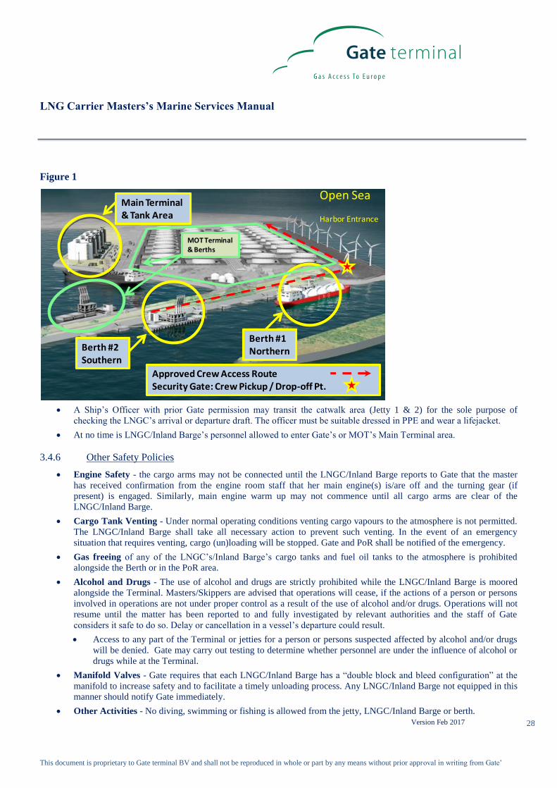
Figure 1
The berths physical location is depicted in Figure 2. This location provides easy access for LNG Carriers with all necessary
auxiliary and handling facilities available nearby.
Figure 2

LNG Carrier Masters’s Marine Services Manual
Version Feb 2017
This document is proprietary to Gate terminal BV and shall not be reproduced in whole or part by any means without prior approval in writing from Gate’
23
3.4. Terminal Policies
3.4.1 General
Responsibilities of the Master of an LNGC or Skipper of an inland barge
Primary responsibility for the safe conduct of operations on board the vessel rests with the Master/Skipper. The Master/Skipper
should take care that he and all other persons on board whilst on board as well as ship’s personnel whilst on the premises of the
Terminal carefully follow all rules, regulations, formalities, measures and directions given and/or to be given by or on behalf
of the authorities and/or Gate.
The Master/Skipper should take care that all agreements made between Gate and persons on board are carefully observed.
All operations on board relative to the LNGC/inland barge and/or the cargo are to be executed under surveillance of the
Master/Skipper, also if such operations are carried out by personnel of Gate.
LNGC’s and Inland Barges must be:
Maintained in class with a member of the International Association of Classification Societies which has prior
experience in classifying LNG Carriers/Inland Barges, and in compliance with all applicable treaties, conventions,
laws, and regulations, as well as the requirements of the LNG Carrier/Inland Barge registry country and of any
relevant governmental authority in the Netherlands, which relate to seaworthiness, design, safety, navigation,
operation, pollution and similar technical and operational matters;
Staffed with a competent crew, including all key officers and a sufficient number ( in accordance with minimum safe
manning certificate issued by ship’s flag state and comply with SOLAS/ADN/RSP) of other crew members fluent in
both written and spoken Dutch and/or English to be able to coordinate with personnel at the Terminal, and a Master,
Chief Engineer, Chief Mate, and Cargo Engineer (and such other officers having responsibilities associated with the
handling of cargo) who are all appropriately licensed fully conversant with, and experienced in, LNG operations;
In compliance with all Safety of Life At Sea (SOLAS) requirements, as recommended by OCIMF and/or SIGTTO (or
ADN and ISGINTT for Inland Barges);
Constructed, safely manned, operated and maintained in compliance with all relevant laws, regulations and standards
applicable to it and as would be exercised by a Reasonable and Prudent Person;
Issued with a valid inspection certificate (no older than 12 months at time of arrival)
Entered (with full Protection and Indemnity coverage) with a P & I Club that is a member of the International Group
Agreement of P & I Clubs;
Seagoing vessels for Jetty 1 & 2 equipped with a near mid-ships manifold to OCIMF standards, able to receive
standard 16” loading arm couplers and a manifold elevation over still water between 15.0 and 27.4 meter
Seagoing vessels and Inland Barges for Jetty 3 equipped with a near mid-ships manifold, able to receive standard 10”
loading arm couplers and a manifold elevation over still water between 3.7 and 18.75 meter
Seagoing vessels equipped with adequate facilities, designed in accordance with OCIMF’s and/or SIGTTO’s
recommendations, for mooring, unmooring, and handling LNG Cargo, i.e:
Inland barges equipped with adequate facilities , designed in accordance with ADN regulations and ISGINTT
guidelines
mooring lines all fitted on drums/winches with brakes and with soft (nylon) tails; capable to pull 30 to 200 kN
pretension in the lines and typical winch brake holding powers between 600 and 900 kN. For small scale vessels
with a length below 115meter) and Inland Barges, mooring lines on bollards may be allowed depending the
outcome of a mooring study
compatible ship/shore communication links (for telecom and data transfer) based on glass-fibre optic system
and/or electric (Pyle) 37-pin backup (to North Atlantic pin allocation standard) in compliance with international
regulations in order to enable the LNGC/Inland Barge to communicate with the Terminal.

LNG Carrier Masters’s Marine Services Manual
Version Feb 2017
This document is proprietary to Gate terminal BV and shall not be reproduced in whole or part by any means without prior approval in writing from Gate’
24
Lifeboat Tests - The vessel is not permitted to test its lifeboats without prior authorisation of Gate and the Port. The launching
of freefall lifeboats, which may be obstructed by mooring lines, is not permitted.
Standby Tugs – May be required in certain weather conditions (see Appendix A – Adverse Weather policy) or when
maintenance has been approved that will affect the manoeuvrability of the LNGC (as specified in 3.4.3 of this manual).
Minimum standard is 60 Ton Bollard pull for Jetty 1 & 2 or 45 Ton Bollard pull for Jetty 3
Direct transfer from ship to ship – For any manipulation of goods which is to take place between the LNGC/Inland Barge
and another vessel, prior permission from Gate is required. Even if Gate has allowed this transfer, it will take place under the
Master’s/Skipper’s responsibility and for account and risk of the Master/Skipper and the owner of the LNGC/Inland Barge and
not for account and risk of Gate.
Utilities – With prior approval by Gate, the following utilities can be arranged by the Ship’s agent for delivery to the berth
after cargo (un)loading.
Freshwater - In general, you will order supplies of potable water before arrival via your agent. Your agent will arrange that
the water barge arrives at the right time. No transfer of water to the ship will be allowed while LNG cargo (un)loading is
ongoing. Reporting of bunkering fresh water is mandatory upon arrival to the Terminal representative.
Ship’s stores/provisions - must be arranged through the Ship’s Agent with proper notification and approval of Gate.
Bulk Ship’s stores/provisions will be loaded from a supply boat aft of the LNGC’s accommodation block using the
Ship’s stores crane;
Small items of stores which can be carried in one hand may be taken from the Berth via the gangway only after
permission from Gate is given.
Bunkering - must be arranged through the Ship’s Agent with proper notification and approval of Gate and will be delivered by
barge.
Water pollution – Unless officially approved, it is forbidden to allow the discharge of substances, in any way or for any
reason at the Terminal or into the water.
Waste Management - There are no disposal facilities available at the Terminal. The LNGC shall provide for the storage of
waste material, including hazardous wastes and oil from pollution incidents or the Ship’s Agent can arrange for waste disposal
by barge. For more information on the PoR policy on waste, see PIG Sections 4.9 and 16.6.
Barges alongside for fresh water, stores, bunkers, waste etc- allowed:
Only after approval of Gate,
After the LNGC/Inland Barge is (un)loaded,
There is sufficient time left before departure. Any delays due to these operations shall be the responsibility of the
ship.
Mooring Winches - All LNGC’s and Inland Barges equipped with automatic line tension capability will be set to manual
while at the berth.
Deck scuppers, drain holes and drip trays on the LNGC within the area of any potential pollution must be suitably plugged
and any accumulated water drained off. Any water drained from the vessel must be free from all polluting agents.
Line Handlers and mooring boats for seagoing vessels must be arranged by the LNGC via its Agent.
Inland Barges must be able to (un)moor without the need for line handlers
3.4.2 LNGC/Inland Barge “State of Readiness”
LNGC/Inland Barge - The Master/Skipper is required to maintain a general state of readiness, therefore:
The LNGC/Inland Barge must maintain sufficient positive stability to ensure the safety of the LNGC/Inland Barge, the
Terminal and the cargo (un)loading process and to be prepared for an emergency unberthing if necessary by:
Managing the LNGC’s/Inland Barge’s ballast water to minimize the reduction in draft created by the cargo
(un)loading process;
Attempting to maintain zero list while at the Berth;
Maintaining the appropriate trim at the berth taking into account the depth of water available.

LNG Carrier Masters’s Marine Services Manual
Version Feb 2017
This document is proprietary to Gate terminal BV and shall not be reproduced in whole or part by any means without prior approval in writing from Gate’
25
Sufficient Crew must be retained aboard the LNGC/Inland Barge to ensure the safety of cargo operations and to face any
emergency that may occur including, departure from the berth.
Crew Rest - All LNGC’s/ crew must be suitably rested and fit for duty in accordance with the obligations ILO Convention N.
180 (Seafarers' Hours of Work and the Manning of Ships Convention) and IMO's STCW Convention, 1978, as amended in
1995.
For Inland Barges regulations according RSP and “Arbeidstijdenwet/Arbeidstijdenbesluit vervoer” are applicable
Engine Readiness - Unless prior written approval has been given by Gate, boilers, generators, main engines, steering
machinery and other equipment essential for manoeuvring must be maintained in standby mode to enable the LNGC/Inland
Barge to use her own engines and steering system at short notice in the event of an emergency un-berthing.
3.4.3 Maintenance and Repairs by LNGC/Inland Barge at berth
Any repair or maintenance work (either Hot Work or Cold Work) which would impair the safety of the cargo
operations (above deck) or the manoeuvrability of the LNGC/Inland Barge is prohibited. In the event that the
LNGC/Inland Barge experiences any incident while alongside which affects the cargo operations or the
manoeuvrability of the LNGC/Inland Barge, Gate shall be immediately notified. Gate and LNGC/Inland Barge shall
agree (initially by Hot Line with documentation in Appendix E1) on appropriate actions to mitigate any dangers to
both parties and the safety of cargo operations.
All other work required by the LNGC while alongside the berth shall be approved by Gate using the Work
Authorization form found in Appendix E1. During the pre-cargo meeting, the vessel will provide the terminal
representative a “daily work plan.” Both the LNGC/Inland Barge and Gate will be required to sign the Work
Authorization form. The LNGC/Inland Barge must comply with its own “Permit To Work” procedures and a full risk
analysis shall be carried out by the LNGC/Inland Barge and discussed with Gate before the Terminal Work
Authorization form will be issued.
In either of the above scenarios, Gate has the right to require the LNGC/Inland Barge to have a standby tug in place to
assure safety while the work is being performed.
For PoR policies regarding Maintenance and Repairs see PIG Section 14.3.
3.4.4 Fire Prevention and Safety Policies – The following shall be adhered to while the LNGC/Inland Barge is at
the Berth
The LNGC’s Safety Plan must be posted adjacent to the gangway, along with a cabin plan and up to date crew list,
and must be available to Gate in case of an emergency.
Personal Protection Equipment (PPE) - Any LNGC/Inland Barge crewmember that leaves the vessel for any reason
must comply with Gate’s PPE requirements in Appendix F.
The LNGC/Inland Barge staff must be familiar with all Gate and MOT Emergency Alarm Signals and policies listed
in Appendix G.
The LNGC/Inland Barge should be familiar with the existence of the Terminal’s firefighting equipment and
capabilities which are listed in Appendix H.
The LNGC’s/Inland Barge’s water spray system (deluge) must be on standby at all times, & capable of being
pressurized at short notice. All fire hoses fitted with dual jet/fog nozzles in the area of the cargo tanks and manifold
area are to be connected to the LNGC’s/Inland Barge’s fire main system and led out, ready for immediate use. The
LNGC’s/Inland Barge’s fire main must be fully pressurized whilst alongside.
The Terminal’s International Shore Connection is located at the upper platform on the berth and looks similar to
Figure 3. The LNGC must connect to it if vessel’s fire main can’t be pressurized with vessels firewater pumps.
Figure 3

LNG Carrier Masters’s Marine Services Manual
Version Feb 2017
This document is proprietary to Gate terminal BV and shall not be reproduced in whole or part by any means without prior approval in writing from Gate’
26
The LNGC’s/Inland Barge’s fixed dry-powder (DP) systems must also be ready for immediate use. If applicable,
hoses shall be led out for those systems used to protect the manifold areas. Portable dry powder fire extinguishers
must be available at each side of the cargo manifold. The vessels fixed DP monitors must be configured and
positioned correctly.
All windows and portholes of the LNGC/Inland Barge must remain closed. All external doors except those
designated for personnel access must remain closed. Those doors designated for personnel access must be closed
immediately after use.
Air conditioning intakes must be set to ensure that the atmospheric pressure inside the accommodation is always
greater than that of the external atmosphere. Air conditioning systems must not be set to 100% recirculation, as this
will cause the pressure of the internal atmosphere to fall to less than that of the external atmosphere, due to the
extraction fans operating in sanitary spaces and galleys.
If at any time it is suspected that gas is being drawn into the accommodation, central air conditioning and mechanical
ventilation systems should be stopped and the intakes covered or closed.
Portable and fixed electric and electronic equipment used in the LNGC’s/Inland Barge’s Hazardous Areas must be
of an approved type for such areas and satisfactorily maintained.
The use of Naked Lights is prohibited on board the LNGC/Inland Barge and in the Terminal.
Smoking in the Terminal is strictly prohibited. Smoking on board the LNGC may only take place in enclosed spaces
that are specifically designated by the Master in consultation with the Marine Supervisor or his representative. A
maximum of two smoking areas are permitted whilst alongside, these must be declared prior to cargo operations
commencing.
On board of Inland Barges smoking is prohibited unless a designated location has at least 2 doors between this room
and the deck area
The use of mobile phones is strictly prohibited in the Hazardous Areas of the Terminal and onboard the
LNGC/Inland Barge, unless of an Ex-approved type. Non-approved types must be switched off. Mobile phones are
only to be used in the accommodation area of the LNGC/Inland Barge with the Master’s/Skipper’s permission;
Matches, lighters and any other sources of ignition, including portable electronic equipment (iPod’s, cameras,
MP3 players, etc.) are not permitted in the Terminal.
3.4.5 Terminal Security
Terminal Security and access is the joint responsibility of Gate and the LNGC/Inland Barge under the International
Ship and Port Security (ISPS) Code. Gate’s Security Officer (PFSO), and the LNGC’s Master or Ship Security

LNG Carrier Masters’s Marine Services Manual
Version Feb 2017
This document is proprietary to Gate terminal BV and shall not be reproduced in whole or part by any means without prior approval in writing from Gate’
27
Officer (SSO) will review and agree to the security measures each will implement. This will be documented by the
signing of the Declaration of Security found in Appendix L4.
Evidence of any serious breach, repeated deficiencies, or significant lack of understanding or implementation of the
requirements of ISPS Code by the LNGC’s/Inland Barge’s Crew may result in cessation of cargo operations and
rejection of an LNG Tanker and or identified crew members or visitors. Above mentioned issues may be identified
via spot checks done by PFSO, Deputy PFSO and/or SSO. The incident will be discussed with the responsible
person(s) after which a Letter Of Protest can be issued. In addition, all visitors and ship’s crew are advised that the
taking of pictures/video of the Terminal is strictly forbidden.
Access to the Terminal is strictly limited to Terminal personnel, the LNGC’s/Inland Barge’s Crew and approved
visitors or contractors.
The LNGC’s/Inland Barge’s arrival crew list, including any embarking personnel must be transmitted by email to
Gate prior to the LNGC’s/Inland Barge’s arrival. LNGC/Inland Barge owner, management personnel, government
officers, vendors (unless not specifically approved), and other visitors with a valid reason for entry and who have
been pre-approved by the Master/Skipper may also be allowed into the Terminal. The list of visiting personnel should
be advised to Gate by email before the arrival of the LNGC/Inland Barge. Any changes to this list must be
communicated to Gate immediately.
The Terminal requires personal photographic identification (seaman’s ID or national ID documents) and reserves the
right to search all visitors, vehicles and packages entering and leaving Gate’s facility. No unaccompanied baggage
will be permitted into the facility. Gate reserves the right to board the LNGC/Inland Barge at any time to ensure that
her Security Plan and applicable regulations are being observed.
Persons on board the LNGC/Inland Barge being present on the Terminal’s premises as well as those who enter the
Terminal’s premises on request of the Master and/or the persons on board, do so entirely at their own risk, also when
this happens with permission of or under escort by Gate. Gate is never liable for death, injury, damage, loss, fines,
costs or other harm incurred by those who set foot on the Terminal’s premises.
Gate reserves the right to refuse entry of personnel, packages vehicles etc. into the Terminal.
Shore leave for members of the LNGC’s/Inland Barge’s Crew will be granted, subject to Customs & Immigration
approval and compliance to Gate policies and procedures.
LNGC/Inland Barge Crew that leave the LNGC/Inland Barge and transit the berth:
Must have a valid photographic ID (seaman’s ID or national ID);
Must comply fully with Gate’s Security Procedures & all Terminal regulations concerning safety;
Must have permission from Gate Security Personnel to transit from the Jetty to the Security gate;
May be subject to drugs and alcohol testing at the security gate, failure to participate in sample or positive
detection will result in access restriction and notification to the Ship’s Master//Inland Barge’s Skipper ;
Must walk directly to and from the Security gate upon leaving the LNGC/Inland Barge;
Are responsible to make necessary arrangements for the collection and drop-off of the Crew at the Terminal’s
Jetty Security gate;
Must follow the (PPE Free) Safety Corridor. A painted line is the designated access route for LNGC’s/Inland
Barge’s Crew to enter or leave the berth from the LNGC/Inland Barge (See Figure 4). Only this area may be
transited by the LNGC’s/Inland Barge’s Crew;
Access to the Terminal Jetty and / or the Safety Corridor to the Jetty Security gate will not be allowed during
cool-down / warm-up, ramp down / ramp up or connection / disconnection of the (un)loading arms.
LNG Carrier Masters’s Marine Services Manual
Version Feb 2017
This document is proprietary to Gate terminal BV and shall not be reproduced in whole or part by any means without prior approval in writing from Gate’
28
Figure 1
Main Terminal& Tank Area
Berth #2Southern
Berth #1Northern
Open Sea
Approved Crew Access RouteSecurity Gate: Crew Pickup / Drop-off Pt.
Harbor Entrance
MOT Terminal & Berths
A Ship’s Officer with prior Gate permission may transit the catwalk area (Jetty 1 & 2) for the sole purpose of
checking the LNGC’s arrival or departure draft. The officer must be suitable dressed in PPE and wear a lifejacket.
At no time is LNGC/Inland Barge’s personnel allowed to enter Gate’s or MOT’s Main Terminal area.
3.4.6 Other Safety Policies
Engine Safety - the cargo arms may not be connected until the LNGC/Inland Barge reports to Gate that the master
has received confirmation from the engine room staff that her main engine(s) is/are off and the turning gear (if
present) is engaged. Similarly, main engine warm up may not commence until all cargo arms are clear of the
LNGC/Inland Barge.
Cargo Tank Venting - Under normal operating conditions venting cargo vapours to the atmosphere is not permitted.
The LNGC/Inland Barge shall take all necessary action to prevent such venting. In the event of an emergency
situation that requires venting, cargo (un)loading will be stopped. Gate and PoR shall be notified of the emergency.
Gas freeing of any of the LNGC’s/Inland Barge’s cargo tanks and fuel oil tanks to the atmosphere is prohibited
alongside the Berth or in the PoR area.
Alcohol and Drugs - The use of alcohol and drugs are strictly prohibited while the LNGC/Inland Barge is moored
alongside the Terminal. Masters/Skippers are advised that operations will cease, if the actions of a person or persons
involved in operations are not under proper control as a result of the use of alcohol and/or drugs. Operations will not
resume until the matter has been reported to and fully investigated by relevant authorities and the staff of Gate
considers it safe to do so. Delay or cancellation in a vessel’s departure could result.
Access to any part of the Terminal or jetties for a person or persons suspected affected by alcohol and/or drugs
will be denied. Gate may carry out testing to determine whether personnel are under the influence of alcohol or
drugs while at the Terminal.
Manifold Valves - Gate requires that each LNGC/Inland Barge has a “double block and bleed configuration” at the
manifold to increase safety and to facilitate a timely unloading process. Any LNGC/Inland Barge not equipped in this
manner should notify Gate immediately.
Other Activities - No diving, swimming or fishing is allowed from the jetty, LNGC/Inland Barge or berth.
LNG Carrier Masters’s Marine Services Manual
Version Feb 2017
This document is proprietary to Gate terminal BV and shall not be reproduced in whole or part by any means without prior approval in writing from Gate’
29
Grounding - The electrical ground cable should not be connected with LNGC/Inland Barge as the cargo arms of
LNG receiving terminal are mounted with insulating flanges (SIGTTO).
3.5. Gate Pre-Arrival Procedures
3.5.1 LNG Pre-Arrival Checks
The LNGC’s/Inland Barge’s crew shall perform pre-arrival checks that (at a minimum) comply with the recommendations of
SIGTTO/ISGINTT. Records shall be maintained and made available to the Terminal and PoR when required. Confirmation of
completion of pre-arrival checks and any deficiencies shall be reported to the terminal in the Pre-Arrival Information notice.
Any defects which may affect the safety of navigation, berthing or cargo operations must also be reported to the PoR as
applicable.
The Pre-Arrival checks will include but not be limited to:
Cargo Readiness - All necessary preparations for handing cargo need to be completed prior to docking at the
Terminal. As a minimum this includes:
Having the proper size manifold presentation flange (Appendix I4a for Jetty 1 & 2 or Appendix I4b for Jetty 3);
Manifold flanges inspected and approved for service prior to arrival;
Scuppers in place;
Fire prevention precautions in place;
Mooring lines and associated equipment inspected and ready for use;
If equipped with a double block and bleed configuration at the manifold: arrive with deck lines as agreed upon
during pre-arrival meeting (warm and empty or pre-cooled and inventoried.)
Necessary documentation is completed and available for review once moored.
3.5.2 LNGC/Inland Barge Pre-Arrival Notice Requirements:
(1) Cargo Information Notice
For each LNG cargo to be (un)loaded via the Terminal, Gate must receive a Cargo Information Notice by email
([email protected] and [email protected]) upon departure of the LNGC/Inland Barge
previous port. The form of the notice can be found in Appendix E2 and includes important information about the
condition of the cargo upon departure and the expected characteristics of the LNG cargo upon arrival at the Terminal.
If the destination of the LNGC/Inland Barge after departure from the previous port was changed to Gate terminal, the
Cargo Information Notice will be delivered to Gate as soon as possible after such acquisition or diversion.
(2) Notice of Arrival
The LNGC/Inland Barge is required to provide Gate with a Notice of Arrival by email ([email protected]
and [email protected]) immediately upon departure from the last port. The notice will include an
estimated time of arrival of the LNGC at the Pilot Boarding Station (ETA) as well as other important information.
For Inland Barges the ETA should be given for arrival at Gate terminal. The LNGC/Inland Barge must also provide
updates at prescribed intervals along the voyage so the Terminal may adequately manage all of its activities and
commitments. The required form for the initial notice and all updates can be found in Appendix E3. The required
update intervals are:
(a) 72 hours before the then current ETA;
(b) 48 hours before the then current ETA;
(c) 24 hours before the then current ETA;
(d) 12 hours before the then current ETA.

LNG Carrier Masters’s Marine Services Manual
Version Feb 2017
This document is proprietary to Gate terminal BV and shall not be reproduced in whole or part by any means without prior approval in writing from Gate’
30
If the destination of the LNGC/Inland Barge after departure from the previous port was changed to Gate terminal, the
Notice of Arrival will be delivered to Gate as soon as possible after such acquisition or diversion and all updates still
possible will be delivered on schedule.
(3) Notice of Readiness
A Notice of Readiness shall be issued to Gate by the LNGC via email ([email protected] and
[email protected]) (on behalf of Gate’s Customer) as soon as the LNGC has reached the Pilot
Boarding Station (situated 7 nautical miles (13 km) before the Maas Center Buoy) and:
(a) has cleared the necessary formalities with the Port Authority, Harbour Master and all other relevant authorities
and has complied with all necessary customs notification requirements and
(b) is ready in all respects to proceed to the Terminal’s (un)loading berth designated by the Terminal and commence
(un)loading
The form of the notice can be found in Appendix E4 and it will be time-stamped by Gate upon receipt
For inland barges the Notice of Readiness shall be issued upon arrival at jetty 3 or, if the jetty is occupied, upon
arrival at her location where she is waiting until requested to proceed to jetty 3.
3.5.3 Terminal Pre-Arrival Notice Requirements
(1) Acceptance or Rejection of the Notice of Readiness:
Gate will accept or reject the NOR following receipt of the notice from the LNGC by email using the form of notice
found in Appendix E5 and Appendix E6.
If the LNGC has tendered the NOR and the Terminal or Master encounters or foresees a problem which will cause a
delay to the LNGC in berthing, unloading or departing the Terminal, it must notify the other party immediately by
email using the form in Appendix E10.
(2) Terminal Status Notice
Gate will provide the LNGC with a Terminal Status Notice at least 24 hours prior to the then current ETA. The form
of this can be found in Appendix E7 and will be given by e-mail.

LNG Carrier Masters’s Marine Services Manual
Version Feb 2017
This document is proprietary to Gate terminal BV and shall not be reproduced in whole or part by any means without prior approval in writing from Gate’
31
3.6. Mooring / Berthing the LNGC
Arriving LNG vessels proceed from the port entrance to the turning basin where they will be turned (as shown in Figure 5a &
5b) and then pushed alongside the appropriate berth (as directed by Gate) by the attending tugs.
Figure 5a
Figure 5b
Berth #3

LNG Carrier Masters’s Marine Services Manual
Version Feb 2017
This document is proprietary to Gate terminal BV and shall not be reproduced in whole or part by any means without prior approval in writing from Gate’
32
The berth and cargo transfer systems are designed for LNG carriers/Inland Barges to moor port side alongside, with the
vessel’s bow facing the sea. This is the required mooring pattern for all vessels moored at the Terminal.
To assist vessels with their approach, the Terminal’s berth is equipped with an approach angle/distance/velocity indicator
board to aid in vessel alignment to the fenders of the berth. (see Figure 6) The maximum approach speed allowed for Jetty 1 &
2 is 12 cm/s (For Jetty 3 the maximum approach speed allowed is 10cm/s) and the maximum permitted angle between the
LNGC’s side and the berth fender is five (5) degrees. Other mooring criteria are shown in Gate’s Adverse Weather Policy
(Appendix A).
Figure 6
Jetty 1 & 2 are designed to accommodate LNGC’s from 95-350 m in length and from 5,000 to 267,000 m3 in size. The
maximum vessel displacement is 210,000 mT.
The berth is equipped with four (4) breasting dolphins and six (6) mooring dolphins with all details and drawings shown in
Appendix Ia and I2a. All dolphins are equipped with double, triple or quadruple quick release hooks and have the ability to
accommodate up to 6 spring-lines and 14 breast-lines.
Breasting Dolphins: Each breasting dolphin is fitted with a double or triple quick-release hook assembly. Each hook in the
assembly is rated at 125t SWL. Every breasting dolphin is equipped with a motorized capstan.
Mooring Dolphins:. The four outer mooring dolphins are each fitted with a quadruple quick-release hook assembly. Each
hook in the assembly is rated at 125t SWL. The two inner mooring dolphins are each fitted with a triple quick-release hook
assembly. Each hook in the assembly is rated at 125t SWL. Every mooring dolphin is equipped with a motorized capstan.
Jetty 3 is designed as a quayside to accommodate small scale LNGC’s from 50 – 180m in length and until 20,000m3 in size
(210 meter and/or 40,000m3 in the future) and Inland Barges until 135m in length and 10,000m3 in size.
She is equipped with 6 triple quick release hook assemblies for headlines, breast-lines and stern-lines and 2 double quick
release hook assemblies for spring lines, see Appendix Ib and I2b.
Each hook assembly is equipped with a motorized capstan and each hook in the assembly is rated at 75t SWL.
Additional there are 20 bollards at 11.15m spacing positioned on the quayside plus 14 bollards recessed into the front of the
quay at 2 elevations (NAP+1.7m and NAP+3.2m).
The Terminal and the LNG carrier shall agree on a mooring configuration and mooring plan prior to arrival which meets
OCIMF guidelines. Synthetic tails of a suitable length and minimum-braking load consistent with OCIMF guidelines shall be

LNG Carrier Masters’s Marine Services Manual
Version Feb 2017
This document is proprietary to Gate terminal BV and shall not be reproduced in whole or part by any means without prior approval in writing from Gate’
33
used on all steel mooring wires and/or HMPE mooring lines. This plan shall be sent to the Pilots with a copy to the linesmen
organisation (de “Eendracht”).
LNGC’s with a length over 115 meter should use the quick release hooks.
Other LNGC’s and Inland barges may use the bollards for their mooringplan.
LNGC’s: Mooring crews/line handlers and boats are arranged by the ship’s Agent to handle mooring lines during berthing and
un-berthing operations. The mooring boat crew will take the LNGC’s mooring lines from the ship allowing mooring lines to be
lifted by the electrically powered capstans that are fitted on the mooring dolphins to assist in hauling the mooring lines towards
the mooring hooks.
Inland Barges: Mooring is done by the crew on board the Inland Barge without assistance of line handlers.
The Master of the LNGC or the Skipper of the Inland Barge will ensure that all mooring lines used are clean and will not
pollute the waters surrounding the Terminal or PoR.
The responsibility for the safe mooring and the tending of mooring lines lies with the Master/Skipper. To assist the Master in
tending the lines, Gate will provide the Master with a wireless laptop at the ship / shore interface (pre-cargo) meeting capable
of displaying line-tension reading on all quick release hooks. The laptop can also provide local weather data. However, in
accordance with the ship/shore safety checklist (Appendix L1), Gate can intervene on this issue if considered necessary. It is
emphasized that care must be given to ensuring that the mooring loads are evenly distributed over the mooring pattern and that
no lines are allowed to become slack or over-tight.
Checks are to be made to ensure that tending of the moorings is maintaining the LNGC in a satisfactory position within the
safe working envelope of the unloading arms (Appendix I6a and I6b ). At the Terminal, a system is in place to automatically
monitor the details of mooring tension.
Fire wires are not needed to be prepared. Both Port authorities and Gate terminal adopted the OCIMF recommendations on
ETOPS (October 2009)
3.7. Gangway Setting
On Jetty 1 & 2 the Terminal gangway will be the designated access between the Terminal and the LNGC. For small scale
vessels on Jetty 1 a smaller terminal gangway is available. For other small scale vessels a portable ship’s gangway can be used
as alternative. All personnel transiting to/from the LNGC shall use this access unless the Terminal and LNGC have come to
another agreement. See Appendix I1 and I3.
As soon as berthing has been completed, the LNGC must notify Gate of her “all-fast“ time and be ready to receive the
Terminal gangway. The Terminal will operate the gangway and land it in the pre-designated area. A non-slip surface must be
provided by the vessel at the base of the gangway. The LNGC is required to assist the Terminal in the safe and proper
positioning of the gangway.
On Jetty 3 there is no terminal gangway. LNGC’s and Inland barges have to use their gangway to arrange a safe access to/from
the terminal. Inland barges can also use the vertical ladders located at the waterfront of the jetty.
The gangway will be inspected by the Terminal and the LNGC/Inland Barge when it is in position and landed. The Terminal
and LNGC will have to agree that the access provided enables the safe transfer of personnel between the Terminal and the
LNGC/Inland Barge. The LNGC/Inland Barge is required to ensure proper lighting of the gangway area and her main deck.
The Terminal will provide lighting on the Terminal side.
3.8. Ship / Shore Communications
Primary ship / shore communications will be provided by means of a glass-fiber optic link or an electric (Pyle National 37 pin)
multi-pin back-up depending on the LNGC’s/Inland Barge’s systems. Only the primary or back-up link will be connected, not
both. This link provides both phone and ESD capabilities. This link will be set immediately after the gangway is landed and
deemed a safe access to the LNGC/Inland Barge. Terminal staff will connect the shore cable, the vessel’s crew is not permitted
to connect or disconnect the shore cable. It will remain operative until the gangway is about to be removed for un-berthing.
The vessel must ensure that the onboard ESD connection is in good condition and clear of any obstructions.
The ESD system shall only be “inhibited” on agreement with the Gate; Gate will require the ESD system to be inhibited during
arm connection / disconnection operations.
For Jetty 3 a Universal Safety Link is available.
Technical details of the Communications/ESD Link may be found in Appendix Ja for Jetty 1 & 2 or Appendix Jb for Jetty 3.

LNG Carrier Masters’s Marine Services Manual
Version Feb 2017
This document is proprietary to Gate terminal BV and shall not be reproduced in whole or part by any means without prior approval in writing from Gate’
34
The link will allow the following:
Hot line between the Terminal and LNGC Bi-directional
ESD LNGC- Terminal Bi-directional
ESD Terminal - LNGC Bi-directional
Mooring Load Monitor Omni directional
All vessels will also be provided with an Intrinsically Safe, portable UHF radio. This radio is for use as communication back
up and also direct communication to the Terminal jetty operation staff, however the primary communication should continue to
be the Hot Line.
When an LNGC is alongside the berth, it should also maintain a listening watch via VHF PoR channel 19. Additional PoR
communications details can be found in the PIG Section 12.
The Language that will be used for all communications between the Terminal and LNGC/Inland barge will be English or
Dutch.
LNGC’s Communication Systems
The use of LNGC’s GMDSS (Global Maritime Distress Safety System) installation for transmitting, except the GMDSS
satellite communications and VHF radio on one (1) watt power, is not authorized while the cargo arms are connected. The
LNGC’s main transmitting aerials must be disconnected and earthed.
The LNGC’s/Inland Barge’s radars shall be switched off while the cargo arms are connected.
Additionally, the LNGC’s AIS unit should also be either switched off at the Terminal or set to a power setting of equal to or
less than 1 watt.
3.9. Ship / Shore Interface Meeting or Pre-Cargo Operation Meeting
The procedures set forth in this MMSM have been established to facilitate a safe, pre-planned cargo operation and must be
adhered to. The Terminal’s Loading master or his representative and the Ship’s Master/ Inland Barge’s Skipper or his designee
will hold a pre-Cargo Operation meeting on board to discuss all items listed in Appendix K – (The Pre-Cargo Operations
Meeting Checklist). The forms referenced in Appendix K must be discussed, completed and agreed to, signified by signing
prior to cargo (un)loading. Some of the required forms are attached as Appendix K1 – K6.
K1 -The Ship Shore Safety Checklist from ISGOTT. Follow-up safety checks will be conducted at agreed intervals
throughout the (un)loading period and the checklist will be signed accordingly sample as attached in.
K2 - Safety Declaration
K3 - LNG Cargo Operations Agreement
K4 - ISPS Declaration of Security
K5 - Statement of compliance
K6 – ADN Checklist
Before the arms are connected, Gate’s Loading master or his representative will board the LNGC/Inland Barge accompanied
by a representative of Gate’s customer for Custody Transfer, mostly a surveyor.
The quantity that will be transferred will be based for Custody Transfer on the LNGC/Inland Barge tanks gauging. To verify
the composition of LNG during cargo transfer, an on-line chromatograph is installed at the Jetty.
3.10. (Un)loading Preparation
As per ISGOTT, SIGTTO and ISGINTT recommendations, grounding cables are not used as the Terminal cargo arms have
insulating flanges.
Unloading of the LNGC via Jetty 1 and 2 will be carried out using three standard 20 inch liquid cargo arms with 16
inch 150 lbs ANSI B16.5 flanges and one 20 inch vapour return arm with 16 inch 150 lbs ANSI B16.5 flanges. If the
number of liquid cargo arms or vapour arms available is different, the LNGC will be notified and agreement will be
made at the pre-cargo operations meeting.

LNG Carrier Masters’s Marine Services Manual
Version Feb 2017
This document is proprietary to Gate terminal BV and shall not be reproduced in whole or part by any means without prior approval in writing from Gate’
35
For loading a LNGC via Jetty 1 and 2 normally 1 liquid and 1 vapour arm will be connected. Loading rate can be up
to 3000 m3/h depending on the shared BOG handling capacity from vessel and terminal.
For loading a LNGC/Inland Barge via Jetty 3, 1or 2 10 inch liquid arms with 10 inch 150 lbs ANSI B16.5 flanges and
1 10 inch vapour arm with 10 inch 150 lbs ANSI B16.5 vapour arm will be connected. Loading rate can be up to
1000m3/h
The LNGC is required to:
Handle LNG densities of 440 up to 480 kg/ m3 at a maximum unloading rate of 14,000m3/h for Jetty 1, 12,500
m3/h for Jetty 2 against an LNG head of approximately 100 meters liquid column at the inlet flange of the cargo
arms, corrected for the installation of the strainers listed below.
Have in-line Strainers with an ASTM 20 Mesh (nominal aperture of 0.84mm) or ASTM 60 Mesh (nominal
aperture of 0.25mm) for each liquid line unless otherwise agreed by Gate. Manifold strainers must be in
accordance with the SIGTTO “Recommendations for the installations of Cargo Strainers on LNG Carriers”
Have a minimum manifold discharge pressure of 85 mLC in order to maintain reasonable unloading rates, and
thus limited berth times.
Having the ability to receive warm vapours from shore at start of unloading process and arrive at the Terminal
with LNG saturation pressures of 70-150 mbarg.
Have a manifold configuration that is based on LNGC manifolds that complies with OCIMF guidelines. Other
type of flange manifold require reducers from manifold flanges dimension to “ANSI 150 DIA 16 inch – smooth
or raised face” (vessel supplied).
The LNGC’s/Inland Barge manifold water curtain shall be started and flow confirmed before the Terminal
manoeuvers the cargo arms aboard. The water curtain shall remain running continuously until completion of cargo
operations & after the final arm has been confirmed gas free and disconnected.
The arms at Jetty 1 and 2 have a special hydraulic clamp system for a 16 inch diameter flange which requires the
LNGC to have smooth or raised finish flanges, (see Appendix I4a).
The arms at Jetty 3 have a special hydraulic clamp system for a 10 inch diameter flange which requires the
LNGC/Inland Barge to have a raised face flange (See Appendix I4b). All arms are equipped with a “dry-break”
emergency release PERC system that will automatically disconnect (ESD 2 - Emergency Shutdown) when the arm is
approaching an over-extension (see Appendix I6a & I6b).
In the event where during (un)loading the LNGC/Inland Barge will consume gas from her cargo tanks, the burnt gas
shall be measured and accounted for in accordance with the GIIGNL LNG Custody Transfer Handbook, Third edition
3.01, GIIGNL 2011 (section 2.1 “General formula for calculating the LNG energy transferred”).
3.11. (Un)loading Arms Connection
Connecting the arms - Gate is responsible for connecting the arms and the LNGC’s/Inland Barge staff may be requested to
assist as appropriate. The Terminal will provide the gaskets for connecting the arms as required. The LNGC/Inland Barge
shall ensure that her lines and valves allow for safe connection.
Control and Supervision - At all times the cargo operations must be supervised onboard the LNGC/Inland Barge by a
qualified/certified person appointed by the Master/Skipper. The person so appointed shall maintain communications with the
Terminal and the Master/Skipper.
Gate Personnel - Two Operators plus a Loading master (or his representative) will be present for the berthing, connection,
cool down and disconnection of the LNGC/Inland Barge
Cargo Equipment Condition - The Master/Skipper is required to ensure that all the LNGC’s/Inland Barge’s equipment used
in or essential to the safe and efficient cargo operation is properly manned and maintained throughout the cargo operation. Any
deficiency that impacts the safety or efficiency of the cargo operation must be immediately reported to Gate.
Cargo Measurement - The LNGC/Inland Barge is required to conduct initial and final gauging of the cargo tanks prior to the
start of and after completion of cargo operation. The Master/Skipper shall ensure that the cargo gauging is done in compliance

LNG Carrier Masters’s Marine Services Manual
Version Feb 2017
This document is proprietary to Gate terminal BV and shall not be reproduced in whole or part by any means without prior approval in writing from Gate’
36
with the LNGC’s/Inland Barge’s Custody Transfer Measurement System (CTMS) Manual. Gate and a Representative of
Gate’s customer will witness the Cargo Gauging and an Independent Marine Surveyor (if present) will certify the results.
3.12. Cargo Operation
Gate Personnel - One operator will be in attendance at the berth/LNGC/Inland Barge during cargo operation covering the
berth manifold and interim ship safety walks.
Open Vapour Line - Return vapour shall be sent to/from the LNGC/Inland Barge by the Terminal using gas from its LNG
storage tanks. During unloading the LNGC/Inland Barge shall control the return vapour pressure it requires, during loading the
terminal shall control the return vapour. The vessel must ensure that all vapour flow meter readings are recorded prior to and
after vapour transfers with the terminal.
Arm Cool-Down - The (unloading) LNGC or the (loading) terminal/LNGC/Inland Barge shall cool-down the arms at a rate
of max 3oCelsius/min by supplying LNG at approximately 2.0 – 3.0 barg to the arm at a reduced flow of approx 50 m3/hr.
LNGC shall adjust cool-down line pressure/flow at the Terminals direction. The LNGC’s control of LNG flow and pressure
during LNG arm cool-down shall be mutually agreed during the Pre-CargoMeeting. Gate will monitor the cool-down and ask
the LNGC to increase or decrease the LNG pressure as required. Arm cool-down takes approximately 60 minutes shore side.
The LNGC/Inland Barge is responsible for ensuring effective cooling down of its pipeline system in a timely manner so as not
to delay cargo operations.
(Un)loading Commencement - The commencement of cargo (un)loading shall be mutually agreed between Gate and
LNGC/Inland Barge. The party who is pumping shall notify the other party of the time it starts the first and subsequent pumps.
Additional pumps shall only be started after both have verified its ability to handle the increased rate. Each arm at Jetty 1 and 2
have a maximum rate capability of 6000 m3/h (3 arms =14,500 m3/h on Jetty 1 & 12,500 m3/h on Jetty 2. Difference is due to
surge pressure prevention). At no time should this rate be exceeded. The maximum bulk rate will be stipulated by Gate during
the Pre-Cargo Meeting.
At Jetty 3, the maximum loading rate is 1000m3/h
Cargo operation - The LNGC/Inland Barge and Gate will monitor the (un)loading rate, temperatures and pressures
throughout the cargo operation. The LNGC/Inland Barge is to notify Gate hourly of the quantity aboard the LNGC, the rate
and the estimated time for completion of the operation.
Shore Sampling - Gate will take samples of the LNG and analyze them with its on-line gas chromatograph (located at the
Jetty).
(Un)loading Completion - Cargo unloading shall stop at the agreed heel to remain onboard the LNGC. Cargo loading shall
stop at the agreed volume received by the LNGC/Inland Barge. (ship’s stop)
The LNGC/Inland Barge shall notify Gate one hour prior to commencing a reduction of the cargo (un)loading rate. The LNGC
or Gate notifies the other party of the time it stops a pump and the pump number.
In the event that the LNGC is to heel out (i.e. for passage to dry dock or other reasons) the terminal shall be notified at
least 96 hours in advance of this requirement detailing the additional time required to accommodate the activity. This
amount shall be agreed by Gate and LNGC during the Pre-Cargo Meeting, taking into account the remaining capacity
in the shore storage tanks and the Terminal berth schedule.
3.13. Unscheduled Cargo Operation Stoppage
If conditions require that cargo (un)loading be stopped, Gate and LNGC/Inland Barge should endeavour to notify the
other party beforehand. If this is not practical, they shall stop cargo operation and communicate the situation to the
other as soon as it is practical.
Cargo operations must be stopped if there is a failure in communication between the terminal and the LNGC/Inland
Barge.
Gate reserves the right to delay or stop the cargo operation due to operational requirements of the Terminal.
(Un)loading Limits - Gate and LNGC/Inland Barge will monitor the weather and the LNGC’s/Inland Barge’s motion
throughout the cargo operation. If the weather or the LNGC’s/Inland Barge’s motion endangers the Terminal or the
LNGC/Inland Barge, either side shall stop the cargo operation.

LNG Carrier Masters’s Marine Services Manual
Version Feb 2017
This document is proprietary to Gate terminal BV and shall not be reproduced in whole or part by any means without prior approval in writing from Gate’
37
Gate’s full Adverse Weather Policy is shown in Appendix A.
In any event, Gate reserves the right to require the LNGC/Inland Barge to have a standby tug with sufficient
power in place should Gate believe, in its best judgment, the current or expected weather conditions justify the
presence of a tug to increase the safety of the Terminal and the LNGC/Inland Barge.
If conditions affect the safety or efficiency of the cargo (un)loading by either side, it shall be communicated
immediately to the other.
3.14. (Un)loading Completion
Draining & Purging cargo arms – Once the vessel’s staff confirms cargo operations are completed and manifold valves are
confirmed closed, Gate will be responsible to drain and purge the arms. Complete draining and purging operation will be in
close communication and cooperation between ship and shore to prevent unsafe situations. As a guiding rule;
pressurize and drain inboard part of the arm 1 time to shore side,
pressurize and drain outboard part of the arm to ships side till empty,
pressurize and drain inboard part of arm to shore side till empty,
Continue with next arm.
Once all arms are drained and confirmed to be free of liquid, purge all arms to below 2% methane content in a
nitrogen environment, depressurize all arms and start disconnection
Cargo Arms Disconnection - Gate is responsible for disconnecting the cargo arms and the LNGC’s/Inland Barge’s staff may
be requested to assist as appropriate. The LNGC/Inland Barge shall ensure that her lines and valves allow for a safe
disconnection. The Terminal and LNGC’s/Inland Barge’s staff will blind their respective connections after the arms are
disconnected.
Terminal / LNGC/Inland Barge Post Cargo Operations Meeting - A post Cargo Operations meeting will be held on board
immediately after the cargo operation and all items in Appendix L shall be discussed and any issues documented. The Loading
master or his representative and the Master’s/Skipper’s designated person in charge shall attend this meeting.
THE SAFETY OF THE TERMINAL AND LNGC/INLAND BARGE SHALL BE OF PARAMOUNT IMPORTANCE
THROUGHOUT THE LNGC’S/INLAND BARGE’S STAY AT THE BERTH.
3.15. Un-berthing
The Master/Skipper is bound to leave the berth and dedicated LNG basin (the “Nijlhaven”/”Yukon haven”) as soon as possible
after termination of cargo operation. Gate has the right to demand that the LNGC/Inland Barge be removed from her berth
when Gate deems this necessary for reasons of safety, compliance with safety regulations and/or directions from the harbor
authorities or other authorities, upon the end of the Allowed Unloading Time (see Appendix B) or for any other valid reason.
If the LNGC/Inland Barge does not leave the berth timely, then Gate may take all safe and necessary steps to effect the
removal of the LNGC/Inland Barge from the Terminal’s berth and dedicated LNG basin.
Gate will notify the Master/Skipper of the remedies it plans in the event that a LNGC/Inland Barge fails to leave berth timely
using the form in Appendix E9. Gate will use reasonable endeavours to notify the Master/Skipper in the event it is required to
cancel the next berthing slots due to the fact that the LNGC/Inland Barge fails to leave the berth in a timely manner, using the
form in Appendix E8.
Upon completion of the Post-Cargo Operations Meeting, Gate will give notice to the LNGC/Inland Barge that it is “ready to
retrieve the Gangway” and will disconnect the communication links.
Prior to the commencement of un-berthing, the Master and Pilot shall exchange information that allows for the safe passage of
the LNGC from the Berth to the pilot station. This shall include any necessary discussions with Gate or PoR regarding passage
restrictions due to other LNGC’s located at another Gate berth or any incoming LNG traffic. Bridge Team Management
practices shall be utilized to enhance the safe navigation of the LNGC.

LNG Carrier Masters’s Marine Services Manual
Version Feb 2017
This document is proprietary to Gate terminal BV and shall not be reproduced in whole or part by any means without prior approval in writing from Gate’
38
Tugs shall be made fast prior to Stand By Engines and the testing of the main engines ahead and astern. The mooring lines
shall not release until the above has been verified.
The Master and Pilot shall ensure that Gate is aware of the order for releasing mooring lines.
The Skipper on Inland Barges will ask permission from Gate before unberthing and inform PoR via the appropriate VHF
channel.
Unberthing Limits
In order to protect the Berth and LNGC the following maximum unberthing limits have been set:
(See Appendix D1 or D2)
3.16. Gate Terminal (Un)loading Sequence of Events
(1) Mooring / Berthing
(2) “All fast” or “Ready to Receive Gangway” Notice by LNGC/Inland Barge (Laytime Clock Starts)
(3) Setting of the Gangway
(4) Satisfaction of Immigration & Customs Requirements
(5) Installation of ESDS (Emergency Shutdown System) / Communications links
(6) Ship / Shore Pre cargo operations Meeting or Interface Meeting
(7) (Un)loading Process
(a) Start Water Curtain
(b) Connect cargo Arms
(c) Arm(s) Purging with N2 / Leak Test
(d) Initial Gauging (Opening CTS)
(e) ESD’s test Warm Condition
(f) LNGC/Inland Barge cargo lines (if needed) & Arm Cooling Down
(g) ESD’s test Cold Condition
(h) Start Cargo operations
(i) Sampling Onshore
(j) Finish Cargo operations
(k) Inhibit ESD
(l) Drain Liquid Arms
(m) Close Vapour Return
(n) Final Gauging (Closing CTS)
(o) Purging the Liquid Arms
(p) Disconnecting Liquid Arms
(q) Purging Vapour Return Arm
(r) Disconnecting Vapour Arm
(s) Stop Water Curtain
(8) Ship / Shore Post cargo operations Meeting or Closing Meeting
(9) Disconnection ESD’s / Communication Links
(10) “Ready to Retrieve Gangway” Notice Gate (Laytime Clock Stops)
(11) Removing of Gangway
(12) Un-berthing

LNG Carrier Masters’s Marine Services Manual
Version Feb 2017
This document is proprietary to Gate terminal BV and shall not be reproduced in whole or part by any means without prior approval in writing from Gate’
39
4. Appendices
4.1. Appendix A – Adverse Weather Policy:
ACTIVITY at LNG Jetty WIND
(m/s)
SEA
(Meter) ACTION
Berthing: NW - W wind & wave
S – SW wind & wave
Un-berthing:
NW – W wind
S – SW wind
Note:
Limits depend on available tug capacity
> 13.8
> 13.8
> 13.8
> 13.8
> 2.7
> 2.7
n.a.
n.a.
Berthing suspended
Berthing suspended
Departure suspended
Departure suspended
Forecasted wind speeds during expected
period alongside > 13.7 m/s, then all berthing
operations suspended.
(Un)loading
LNG alongside Jetty
Notes:
When mooring loads exceed set alarm
levels, and lines cannot be balanced to
remove peaks, then cargo operations will
stop.
If trends in vessel motions indicate ESD 1
limits will be approached, cargo
operations will stop.
Either action will lead to discussion
between Vessel Traffic Controller (PoR),
LNG terminal (Gate), and ship’s master
or Barge’s Skipper on necessity to take
follow-up measures.
21
17
20
> 21
> 17
SWELL
1.0 m
1.0 m
1.0 m
1.0 m
(Swell measured at jetty)
Put dedicated tug on active stand-by
Discuss Forecast to STOP (un)loading.
STOP (un)loading
Disconnect cargo arms
Forecasted. Discuss situation with traffic
controller, pilot, and ship’s Master or Inland
Barge’s Skipper.
If prognosis is for further deterioration, then:
(1) Disconnect cargo arms
(2) Remove gangway
(3) Pilot on Board (not for Inland Barge)
(4) Tug to support mooring integrity.
Actual Discuss situation with PoR Traffic
Controller, Pilot, and ship’s Master; issues to
consider: -
additional moorings
ship stability
unberthing ship or Barge
OTHER CRITERIA
Electrical Storms
In the vicinity or at the Terminal
Rolling/Listing
Rolling
Listing
Applicable to LNG Jetty
STOP cargo operations, close all ship tank valves
and vents until storm has cleared the Terminal and
poses no further threat.
STOP cargo operations if vessel rolls 2°, i.e. 1°
either side of the upright position, or earlier if
discretion dictates.
Weather forecast & ships stability to be discussed
between Ship Master & Vessel Traffic Controller.
STOP cargo operations at 3°. Ship to close all
cargo valves and take corrective action

LNG Carrier Masters’s Marine Services Manual
Version Feb 2017
This document is proprietary to Gate terminal BV and shall not be reproduced in whole or part by any means without prior approval in writing from Gate’
40
4.2. Appendix B – Allowed Laytime & Allowed Unloading Time for LNGC’s
Size carrier (m3) Allowed Unloading Time (hrs) Allowed Laytime (hrs)
From To
65000 70000 24 20
70000 80000 25 21
80000 90000 26 22
90000 100000 27 23
100000 145000 28 24
145000 155000 29 25
155000 165000 30 26
165000 175000 31 27
175000 185000 32 28
185000 195000 33 29
195000 205000 34 30
205000 215000 35 31
215000 225000 36 32
225000 235000 37 33
235000 245000 38 34
245000 255000 39 35
255000 265000 40 36
265000 275000 41 37
Allowed Laytime starts at the LNG Carrier's notice of LNG Carrier in final position and ready to receive gangway and Actual
Laytime stops when the last flange of the Terminal liquid cargo arms and vapour return line is disconnected from the LNG
Carrier manifold presentation flanges and Gate's notice of ready to retrieve gangway.
Allowed Unloading Time starts with acceptance of the NOR and Actual Unloading Time stops upon the LNG Carrier
departing from the Terminal's dedicated LNG Channel.

LNG Carrier Masters’s Marine Services Manual
Version Feb 2017
This document is proprietary to Gate terminal BV and shall not be reproduced in whole or part by any means without prior approval in writing from Gate’
41
4.3. Appendix C – LNG Carrier Contact Information
Cargo number ETA ETD
Please include International Dialing and prefix number with each contact number
Organization Telephone Fax Email
Vessel
Owner
Vessel’s Manager
Duty Manager
Charterer
Local Agent
P&I Club

LNG Carrier Masters’s Marine Services Manual
Version Feb 2017
This document is proprietary to Gate terminal BV and shall not be reproduced in whole or part by any means without prior approval in writing from Gate’
42
4.4. Appendix D1 – Safety and Admission Policy for LNG Carriers (Nijlhaven, Jetty 1 & 2)
Manoevre Arrival Nijlhaven UKC Policy 0,50 m static
Size restriction Vessels max l.o.a. 345 m.
Tidal restriction 1. L < 120 meter: No restrictions
L > 120 meter: Passing “Lower Leading Light: HW + 00:30 till HW + 01:30 and HW + 04:30 till next HW – 02:30
(distance LNG pilot station – lower leading light = 16 nM)
Wind restriction Max 13,8 m/s (Max 6 Bft)
A wave height of about 2,4m will result in pilotage being “suspended for small shipping (L<125m)” A wave height of about 3,2m is the critical height for suspended pilotage for all shipping.
If suspended there are 2 options:
1. Pilot comes on board by helicopter (free of charge when pilotage is suspended) – VHF Maas Approach will ask if the ship can accept a pilot via a helicopter. This can be done in daytime for ships (L>125m), in nighttime for ships
(L>150m). 2. Ship needs to wait (go at anchor or stem the current)
Visibility restriction LNG Carriers: 2000 meters at sea, 2000 meters in port
Speed restriction N/A
Pilot boarding by small tender: Pilot ladder 2 feet above the water, speed 5 knots Pilot boarding by large tender: Pilot ladder 6 feet above the water, speed 5 – 7 knots
Passing requirements Articles 6.6 and 6.7 of the Port Regulations are in force.
Vessels that have obtained exemption from this article from the Harbour master must maintain a minimum distance of 200
meter to the manifold of the LNG carrier if it is performing cargo operations
If a berth is occupied by a LNG carrier, another LNG carrier cannot pass
If berth 1 is occupied by a LNG carrier, a LNG carrier moored at berth 2 can depart by leaving via the south side (backing up) A LNG carrier is not allowed to enter the harbour basin via the north side
Tug use L > 250 m: minimum 4 tugs, minimum bollard pull 60 tons, stand by at harbour entrance
L < 250 m: minimum 2 tugs, minimum bollard pull 60 tons, stand by at harbour entrance
L < 180 m: minimum 1 tug, minimum bollard pull 60 tons, stand by at harbour entrance
Berthing requirements N/A
Free text option L≥180m, 2 pilots boarding
L<180m, 1 pilot boarding General: Vessels with a freeboard > 9 m must provide an accommodation ladder in addition to the pilot ladder. Pilots refuse
to use mechanical pilot hoists. The decision to board via tender or helicopter is made by the pilot.
Boarding by helicopter: Pilots will board by hoist cable, or, if the vessel is equipped with full landing gear, the helicopter will land on deck. Instructions to the crew: never touch the line or the pilot. Pilots do not require assistance during the hoisting
procedure. Just stay well clear of the line and the pilot. The location for boarding the pilot is at the discretion of the helicopter
pilot and depends on the type of ship. If the location is the bridge wing, remove the rubber mats (so helicopter line can make contact with steel) major course changes should be avoided during the hoisting and landing operations
Manoevre Departure Nijlhaven UKC Policy 0,50 m static
Size restriction Vessels max l.o.a. 345 m.
Tidal restriction N/A
Wind restriction See arrival
Visibility restriction See arrival
Speed restriction See arrival
Passing requirements N/A
Tug use L > 250 m: minimum 2 tugs, minimum bollard pull 60 tons, number of tugs determined by pilot
L < 250 m: minimum 1 tug, minimum bollard pull 60 tons, number of tugs determined by pilot
Unberthing requirements N/A
Free text option See arrival

LNG Carrier Masters’s Marine Services Manual
Version Feb 2017
This document is proprietary to Gate terminal BV and shall not be reproduced in whole or part by any means without prior approval in writing from Gate’
43
Safety and admission policy for LNG carriers general nautical admission policy LNG carrier
1 Deep Sea Pilotage is not compulsory, but recommended.
2. ETA and ETD reporting policy is uniform to deep draught ships (ETA 48 hours before arrival, ETD 12 hours before departure).
3. Other reporting issues: Security, Dangerous Goods, Waste, International Oil Pollution Prevention Certificate (IOPP) according to existing policy.
4. Pilot boarding station:
Arrival: Abeam of buoy E9 (52o 00.2’N 003o 35.0’E). Use of PPU (Portable Pilot Unit) is always compulsory, uniform with deep draught ships.
Departure: At MNW3 – MW4 buoy
5. Departure of LNG carriers will be scheduled depending on traffic situation according to existing policy.
6. Passenger ships, passenger ferries have priority above LNG carriers.
7. Mooring configurations to be sent to Harbour Master and linesmen association.
8. Escort by patrol vessel: uniform to deep draught ships policy (starting from Maas Center up to berth)
9. Crossing traffic at junction Beerkanaal - Calandkanaal will be regulated.
10. No crossing traffic on departure of LNG carriers between the port entrance (harbour lights) and the “Lage Licht”.
I.e. no incoming vessels destined for the river Nieuwe Waterweg during this period.
11. During cargo operations no other vessel activities are allowed in the LNG harbour basin. This item deals with activities on board the (unloading)
LNG carrier. E.g. lowering of life boats for training purposes will not be permitted or “hot” work (welding or flame cutting) on board will not be
permitted.
4.5. Appendix D2 – Safety and Admission Policy for LNG Carriers (Yukon haven, Jetty 3)
Manoevre Arrival Yukonhaven UKC Policy 0,50 m static
Size restriction Vessels max l.o.a. 180 m.
Tidal restriction N/A
Wind restriction Max 13,8 m/s (Max 6 Bft) First 15 calls
Visibility restriction LNG Carriers: 2000 meters at sea, 2000 meters in port
Speed restriction N/A
Passing requirements N/A
Tug use 2 Tugs, minimum bollard pull 45 Tons – (first 15 calls, secured or stand by only, not for inland barges)
If the vessel can demonstrate adequate maneuverability (e.g. it is equipped with Azipods or high lift rudders) the pilot might
deviate from this requirement
Berthing requirements Standard mooring bow out. Mooring with bow in is allowed provided that a quick departure can be realized. Vessels with a length of less than 115 meters can secure their mooring lines on bollards (versus Quick Release Hooks)
Free text option One pilot on arrival
Manoevre Departure Yukonhaven UKC Policy 0,50 m static
Size restriction Vessels max l.o.a. 180 m.
Tidal restriction N/A
Wind restriction Max 13,8 m/s (Max 6 Bft) First 15 calls
Visibility restriction LNG Carriers: 2000 meters at sea, 2000 meters in port
Speed restriction N/A
Passing requirements N/A
Tug use 2 Tugs, minimum bollard pull 45 Tons – (first 15 calls, secured or stand by only, not for inland barges) If the vessel can demonstrate adequate maneuverability (e.g. it is equipped with Azipods or high lift rudders) the pilot might
deviate from this requirement
Unberthing requirements N/A
Free text option One pilot on departure

LNG Carrier Masters’s Marine Services Manual
Version Feb 2017
This document is proprietary to Gate terminal BV and shall not be reproduced in whole or part by any means without prior approval in writing from Gate’
44
4.6. Appendix E – Forms Section
4.7. Appendix E1 – Work Authorization Form
Gate LNG Work Authorization
From the Master of M.V. /S.S. __________________________ Date _______________
To: Gate Terminal
I wish to carry out the following repairs/maintenance while alongside your Berth. Repairs/maintenance will/will not* involve
hot work, will/will not* immobilize the Ship and will take approximately _______ hours.
If subsequently it is determined that the repairs/maintenance work is likely to extend beyond the time stated above, the Master
must notify the Terminal Leader and request an extension to the agreed time.
Description of repair/maintenance:
______________________________________________________________________________________________________
______________________________________________________________________________________________________
______________________________________________________________________________________________________
_____________________
* Delete as necessary
The Master will comply with his company’s own Permit To Work procedures and has reviewed the Permit To Work that he
has requested with the Terminal. A full risk analysis has been carried out by the Master and discussed with the Terminal. It is
understood the Master is entirely responsible for ensuring that the repairs/maintenance are carried out safely.
For Ship For Gate Terminal
Name: Name:
Rank: Position:
Signature Signature
Date:
Time:
Date:
Time:

LNG Carrier Masters’s Marine Services Manual
Version Feb 2017
This document is proprietary to Gate terminal BV and shall not be reproduced in whole or part by any means without prior approval in writing from Gate’
45
4.8. Appendix E2 – Cargo Information Notice (also known as Notice of Departure)
Send to [email protected] and [email protected]
Info description Name, Number, Value
Name Capacity User
LNG Carrier Name & IMO number/ Inland Barge name & ENI number
Cargo ID#
Last Port
Last port Departure Time and Date
Estimated Time of Arrival (ETA) at the Pilot Boarding Station/ Gate terminal
Quantity of LNG loaded in m3 (total) OR heel (ROB) on board
Vapour pressure
Temperature of the liquid
Quality of the LNG on board Value
Wobbe Index
Gross calorific value of LNG
Density of LNG
PPM sulfur in LNG
% of chemical components Components Units Value at Load Port
Methane CH4 % Mol
Ethane C2H6 % Mol
Propane C3H8 % Mol
Iso Butane i-C4H10 % Mol
N-Butane n- C4H10 % Mol
Iso Pentane i-C5H12 % Mol
N-Pentane n-C5H12 % Mol
N-Hexane n- C6H14 % Mol
Nitrogen N2 % Mol
Oxygen O2 % Mol
Carbon dioxide CO2 % Mol
Quantity of LNG to be (un)loaded in m3 (less fuel & boil off
during the voyage)
Quantity of LNG to be (un)loaded in MWh (less fuel & boil off during the
voyage)
Other remarks (e.g. factors affecting voyage time or unloading rate)

LNG Carrier Masters’s Marine Services Manual
Version Feb 2017
This document is proprietary to Gate terminal BV and shall not be reproduced in whole or part by any means without prior approval in writing from Gate’
46
4.9. Appendix E3 – Notice of Arrival Information
Send to [email protected] and [email protected]
Pre-arrival information questionnaire
Question LNG Carrier Comments
Name of LNG Carrier/Inland Barge
Call Sign
IMO / ENI No.
Country of Registry
Name of Master / Skipper
Name of Owner / Operator (Transporter)
Total Number of persons onboard
ETA
Current position, direction and speed Optional
LNG consumed since last port Optional
Last Port of Call
Date of International Oil Pollution Prevention Certificate (IOPP)
Confirm that Passage Plan has been prepared for the voyage and covers the period berth to berth.
Confirm that the primary and secondary cargo measurement systems are functioning
Confirm that all cargo monitoring systems are operational and that void space atmosphere monitoring systems are functioning.
Anticipated quantity to (un)load
Sailing displacement
Anticipated berthing displacement
Distance of manifold vapour connection to stern, bow, and bridge
Confirm that all moorings are on powered reels but will not be left on ‘auto’ once vessel is moored
Anticipated cargo (un)loading rate
Anticipated (un)loading Time
Ship’s deficiencies that would affect port performance including the need for repairs
Requirements for nitrogen, fuel, water, stores garbage removal that will be taken from third parties
Cargo density in KG/M³
Cargo Temperature
Anticipated Saturated Vapour Pressure on arrival
Ship Inmarsat No’s: Voice No.
Voice No.
Fax No.
Telex No.
Ship GSM : Mobile Phone No
Ship Email:
MMSI No.

LNG Carrier Masters’s Marine Services Manual
Version Feb 2017
This document is proprietary to Gate terminal BV and shall not be reproduced in whole or part by any means without prior approval in writing from Gate’
47
4.10. Appendix E4 – Notice of Readiness
Send to [email protected] and [email protected]
Dear Sirs,
This is to inform you that the LNG Carrier , owned by under my command, has arrived at
the Pilot Boarding Station at ……………………………. hours, has cleared the necessary formalities with the Port Authority,
Harbour Master and all other relevant authorities, has complied with all necessary customs notification requirements and is
ready in all respects to proceed to the berth designated by Gate and commence unloading her cargo of LNG.
The pressure of each tank of the LNG Carrier is at the moment:
Tank nrs 1 2 3 4 5
Pressure measured at CTS
Yours Faithfully,
<Date>, <time>
Master
Observations:
Capacity User Unloading port:
Gate LNG Terminal
Notice accepted by
Mr.
Signature
at Gate Terminal on the
Date:
at hour, min

LNG Carrier Masters’s Marine Services Manual
Version Feb 2017
This document is proprietary to Gate terminal BV and shall not be reproduced in whole or part by any means without prior approval in writing from Gate’
48
4.11. Appendix E5 – Acceptance of the Notice of Readiness
Dear Sirs,
We accept the Notice of Readiness and in the table below we give you the details to berth.
Name
Capacity
User
Cargo ID # IMO number
LNG Carrier
Berthing
priority
and time
Berth
number
Allowed
(Un)loading
Time
Allowed
Laytime
Yours Faithfully
<Date>, <Time>
For and on behalf of Gate

LNG Carrier Masters’s Marine Services Manual
Version Feb 2017
This document is proprietary to Gate terminal BV and shall not be reproduced in whole or part by any means without prior approval in writing from Gate’
49
4.12. Appendix E6 – Rejection of the Notice of Readiness
Dear Sirs,
The Notice of Readiness tendered at <date>, <time> is rejected. The reason for the rejection is mentioned in the table below:
Name
Capacity
User
Cargo ID
#
IMO
Number
LNG Carrier
Reason for rejection
Yours Faithfully
<Date>
For and on behalf of Gate

LNG Carrier Masters’s Marine Services Manual
Version Feb 2017
This document is proprietary to Gate terminal BV and shall not be reproduced in whole or part by any means without prior approval in writing from Gate’
50
4.13. Appendix E7 – Terminal Status Notice
Dear Sirs,
We herewith send you the Terminal Status Notice for the <LNG Carrier name>, <LNG Carrier IMO nr>
Name Capacity User
Cargo ID
Details relating to any
restrictions at the Terminal,
which will impact upon the
(un)loading of the Cargo
Timing and rate of (un)loading
Any non-availability of jetty
equipment
Weather forecast at Unloading
Port
Yours Faithfully
<Date>
For and on behalf of Gate
LNG Carrier Masters’s Marine Services Manual
Version Feb 2017
This document is proprietary to Gate terminal BV and shall not be reproduced in whole or part by any means without prior approval in writing from Gate’
51
4.14. Appendix E8 – Notification of need to cancel subsequent Berthing Slot (due to LNG Carrier failing to leave berth in a timely manner)
Dear Sirs,
We herewith notify you that, due to the fact that your LNG Carrier with IMO number <IMO number> failed to leave the berth
in a timely manner, we may be required to cancel the next Berthing Slot, which starts at [date, time].
Yours Faithfully
<Date>
For and on behalf of Gate

LNG Carrier Masters’s Marine Services Manual
Version Feb 2017
This document is proprietary to Gate terminal BV and shall not be reproduced in whole or part by any means without prior approval in writing from Gate’
52
4.15. Appendix E9 – Gate Remedies for LNG Carrier Delays
Dear Sirs,
Your LNG Carrier with IMO number <IMO number>, failed to leave berth in time and exceeds the Allowed Unloading Time.
We plan to undertake the following actions:
-
-
-
-
The reasons for these actions are………
Yours Faithfully
<Date>
On and behalf of Gate

LNG Carrier Masters’s Marine Services Manual
Version Feb 2017
This document is proprietary to Gate terminal BV and shall not be reproduced in whole or part by any means without prior approval in writing from Gate’
53
4.16. Appendix E10 – LNG Carrier / Gate Notice of Delay after Tendering the NOR
Dear Sirs,
We herewith notify you that a problem occurred / is foreseen that will cause a delay to the LNG Carrier in
berthing/unloading/departing. Please find the details in the table below.
Cargo ID# IMO number
LNG Carrier
NOR tendered
at: (hrs:min)
Nature and cause of delay Estimated
delay (in
hrs:min)
We propose to discuss the situation soonest.
Yours Faithfully
<Date>
For and on behalf of <Name Master>/Gate

LNG Carrier Masters’s Marine Services Manual
Version Feb 2017
This document is proprietary to Gate terminal BV and shall not be reproduced in whole or part by any means without prior approval in writing from Gate’
54
4.17. Appendix E11 - Customer & Supplier info for cargoes
ISO standard required for gauging devices on board of LNGC’s: ISO 18132-1; 2006
ISO standard for taking the samples: ISO 8943; 2007
Reference temperatures: 25°C for enthalpy and 0°C for volume (so 25/0)

LNG Carrier Masters’s Marine Services Manual
Version Feb 2017
This document is proprietary to Gate terminal BV and shall not be reproduced in whole or part by any means without prior approval in writing from Gate’
55
4.18. Appendix F – LNG Carrier / Gate Notice of Delay after Tendering the NOR
Personal Protection Equipment (PPE) - Any LNG Carrier crewmember that leaves the vessel for any reason must
comply with Gate’s PPE requirements
Depending on the reason for leaving the vessel we have different policies:
A crewmember leaving the vessel (e.g. for checking the draft fore and aft) needs to wear full PPE*
A crewmember leaving the vessel and is heading for the main gate with the intention to pass the main gate, a PPE free
corridor is created which must be followed.
The corridor is clearly marked by colored lines and is heading directly from the jetties to the main gate.
If a crewmember without PPE is noticed outside the PPE free corridor, all shore leaves will be denied, meaning that
crewmembers are not allowed to leave the vessel.
Further the matter will be discussed with the responsible persons on board, a report will be made and a Letter of Protest will be
issued.
*Full PPE means:
Safety shoes or –boots
Fire retarding clothes
Safety helmet
Safety glasses
Life vest

LNG Carrier Masters’s Marine Services Manual
Version Feb 2017
This document is proprietary to Gate terminal BV and shall not be reproduced in whole or part by any means without prior approval in writing from Gate’
56
4.19. Appendix G – Emergency Alarms
Alarms for Gate, MOT, Ship, PoR, Etc.
Condition Description of Signal
Fire & Gas alarm Audible Alarm slow whoop 3.5sec on, 0.5sec off
Time that Gate alarms will be tested:
11:00 a.m. local time each first Monday each Month
Time that MOT alarms will be tested:
12:00 a.m. local time each first Monday each Month
Time that Port alarms will be tested:
12:00 a.m. local time each first Monday each Month
Time that Ship alarms will be tested: ___ a.m. local time each ______
LNG Carrier Masters’s Marine Services Manual
Version Feb 2017
This document is proprietary to Gate terminal BV and shall not be reproduced in whole or part by any means without prior approval in writing from Gate’
57
4.20. Appendix H – Fire fighting Equipment / Capabilities
Fire-fighting facilities on the main deck include:
Two elevated remotely operated monitors near the berthing line (to cover loading arms and LNG Carrier manifold)
One remotely operated (lower) monitor at rear of the deck covering the deck manifold area
Water deluge on the front of loading arm risers and front of the column supporting the gangway
Deluge of the gangway
Deluge of the KO drum
An international ship/shore connection to allow the connection of a fire hose from the LNG Carrier
A 4-way hydrant located at the access bridge
Remote fire fighting is possible from the Jetty Monitoring Building as well as the Central Control Room
At the LNG Spillage basin there is a High Expansion Foam system to cover the spilled LNG contained in this basin.

LNG Carrier Masters’s Marine Services Manual
Version Feb 2017
This document is proprietary to Gate terminal BV and shall not be reproduced in whole or part by any means without prior approval in writing from Gate’
58
4.21. Appendix Ia – Jetty 1 & 2 Berth Arrangement Details
Dolphin MD1 MD2 MD3 BD1 BD2 BD3 BD4 MD4 MD5 MD6
Dist to
Manifold C/L 175 135 95 52.5 25 2 -14 -30 -60 -105 -145 -185
Dist to
Berthing line 45.5 45.5 45.5 5.25 5.25 - - 5.25 5.25 45.5 45.5 45.5
Height
Dolphins
above NAP
6 6 6 6 6 - - 6 6 6 6 6
Height of
Fenders C/L
above NAP
- - - 2 2 1.8 1.8 2 2 - - -
Fender
dimension - - -
4.2 x
4.2
4.2 x
4.2
1.4 x
6.5
1.4 x
6.5
4.2 x
4.2
4.2 x
4.2 - - -
Hooks 4 4 3 2 3 - - 3 2 3 4 4
Berth limit
for Hooks
vertical angle
-15
+45
-15
+45
-15
+45
-15
+45
-15
+45 - -
-15
+45
-15
+45
-15
+45
-15
+45
-15
+45
Inner hooks
horizontal
angle
100 100 90 120 90 - - 90 120 90 100 100
End hooks
horizontal
angle
120 120 120 120 120 - - 90 120 120 120 120
Port Side towards berth
Berth Heading 337° toward seaward
Channel Width 200 m
Effective Centre of Fenders below Pier 5.5 m
Pier Height above NAP 7.5 m
Fender face/Berthing line from Jetty face 2.6 m
Permissible Surge Excursion Fwd/Aft ±2.00 m
Permissible Sway Excursion Port/Stbd 5.40 m
Dist of Berth Target to Right of Origin 0.50 m
Dredge Depth Below NAP/ Contractual Depth Below NAP 15m / 14.5m
Wind Speed Specified at 10m Height Max 30 m/s
Current Specified at Depth Max 0.45 m/s
Difference between NAP and HHW/LLW +2.73/-1.52

LNG Carrier Masters’s Marine Services Manual
Version Feb 2017
This document is proprietary to Gate terminal BV and shall not be reproduced in whole or part by any means without prior approval in writing from Gate’
59
4.22. Appendix Ib – Jetty 3 Berth Arrangement Details
Port Side towards berth
Berth Heading 172° toward seaward
Channel Width 120 m
Effective Centre of Fenders below Pier
3 rows cylindrical roll fenders
Length 1500mm
Outer diameter 1000mm
Inner diameter 600mm
Pier Height above NAP 5.0
Fender Face/Berthing Line from Jetty face 1.0 m
Permissible Surge Excursion Fwd/Aft ±3.30 m
Permissible Sway Excursion Port/Stbd 1.50 m
Dist of Berth Target to Right of Origin
Arm A+C Arm A+B Arm B+C
0.0 m -2.50 m +0.3 m
Dredge Depth Below NAP/ Contractual Depth Below NAP 10.5m / 10.0m
Wind Speed Specified at 10m Height Max 30 m/s
Current Specified at Depth Negligible alongside Jetty
Difference between NAP and HHW/LLW +3.25 m / -2.00 m
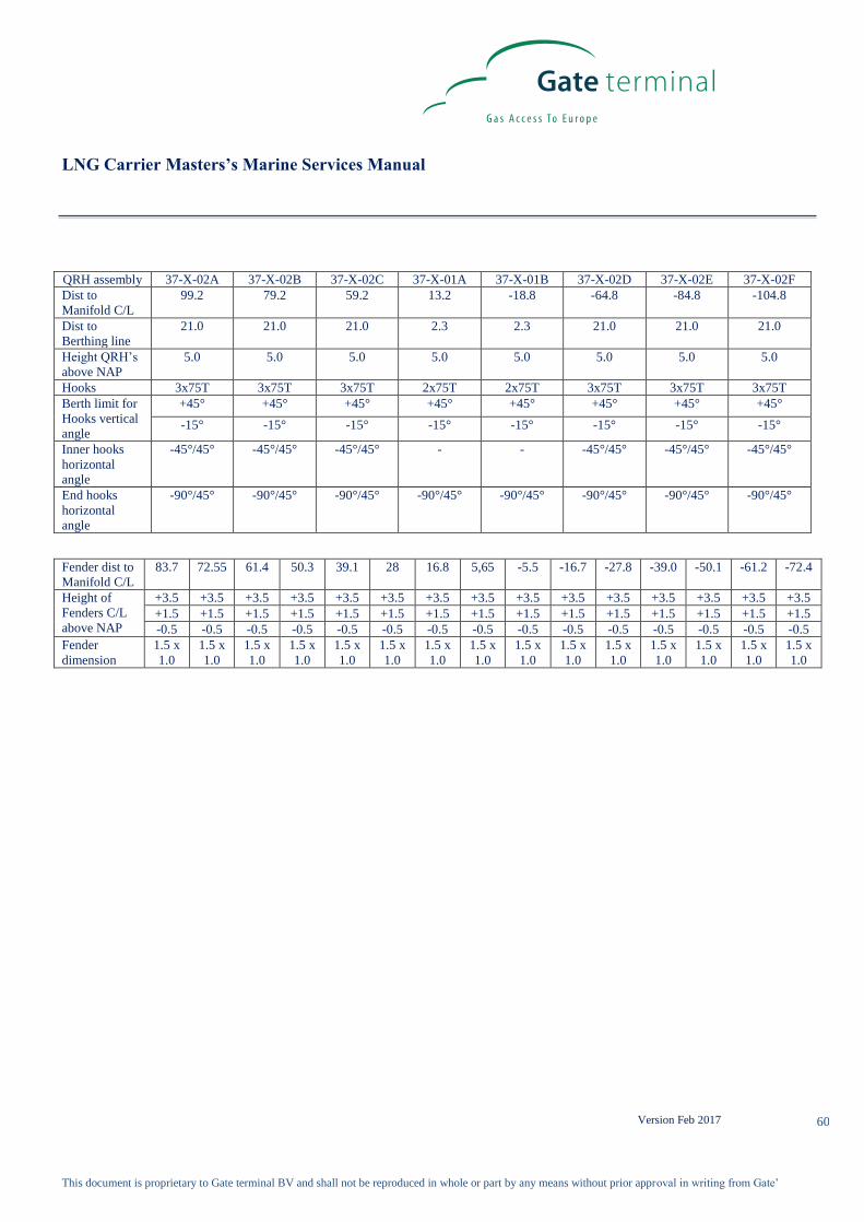
LNG Carrier Masters’s Marine Services Manual
Version Feb 2017
This document is proprietary to Gate terminal BV and shall not be reproduced in whole or part by any means without prior approval in writing from Gate’
60
QRH assembly 37-X-02A 37-X-02B 37-X-02C 37-X-01A 37-X-01B 37-X-02D 37-X-02E 37-X-02F
Dist to
Manifold C/L
99.2 79.2 59.2 13.2 -18.8 -64.8 -84.8 -104.8
Dist to
Berthing line
21.0 21.0 21.0 2.3 2.3 21.0 21.0 21.0
Height QRH’s
above NAP
5.0 5.0 5.0 5.0 5.0 5.0 5.0 5.0
Hooks 3x75T 3x75T 3x75T 2x75T 2x75T 3x75T 3x75T 3x75T
Berth limit for
Hooks vertical
angle
+45° +45° +45° +45° +45° +45° +45° +45°
-15° -15° -15° -15° -15° -15° -15° -15°
Inner hooks
horizontal
angle
-45°/45° -45°/45° -45°/45° - - -45°/45° -45°/45° -45°/45°
End hooks
horizontal
angle
-90°/45° -90°/45° -90°/45° -90°/45° -90°/45° -90°/45° -90°/45° -90°/45°
Fender dist to
Manifold C/L
83.7 72.55 61.4 50.3 39.1 28 16.8 5,65 -5.5 -16.7 -27.8 -39.0 -50.1 -61.2 -72.4
Height of
Fenders C/L
above NAP
+3.5 +3.5 +3.5 +3.5 +3.5 +3.5 +3.5 +3.5 +3.5 +3.5 +3.5 +3.5 +3.5 +3.5 +3.5
+1.5 +1.5 +1.5 +1.5 +1.5 +1.5 +1.5 +1.5 +1.5 +1.5 +1.5 +1.5 +1.5 +1.5 +1.5
-0.5 -0.5 -0.5 -0.5 -0.5 -0.5 -0.5 -0.5 -0.5 -0.5 -0.5 -0.5 -0.5 -0.5 -0.5
Fender
dimension
1.5 x
1.0
1.5 x
1.0
1.5 x
1.0
1.5 x
1.0
1.5 x
1.0
1.5 x
1.0
1.5 x
1.0
1.5 x
1.0
1.5 x
1.0
1.5 x
1.0
1.5 x
1.0
1.5 x
1.0
1.5 x
1.0
1.5 x
1.0
1.5 x
1.0

LNG Carrier Masters’s Marine Services Manual
Version Feb 2017
This document is proprietary to Gate terminal BV and shall not be reproduced in whole or part by any means without prior approval in writing from Gate’
61
4.23. Appendix I-1 – Jetty 1 & 2 – Platform Details
10m/35o
10m/35o
36.0
23.25
NAP + 7.5
A
Shore Access
JETTY #1 JETTY #2
VL
2,5-3,5
2,5-3,5
4,0
4,0
4,0
9,4
2,6 drift 3,0
Jetty #1 = 22,0
A – Gangway working area
L
L
L
V
- Hybrid unloading arm
Jetty #2 = 14.5

LNG Carrier Masters’s Marine Services Manual
Version Feb 2017
This document is proprietary to Gate terminal BV and shall not be reproduced in whole or part by any means without prior approval in writing from Gate’
62
4.24. Appendix I-2a – Jetty 1 & 2 Typical Mooring Plan

LNG Carrier Masters’s Marine Services Manual
Version Feb 2017
This document is proprietary to Gate terminal BV and shall not be reproduced in whole or part by any means without prior approval in writing from Gate’
63
4.25. Appendix I-2b Jetty 3 typical Mooring plan
Frontview of Jetty 3 with cylindrical fenders, vertical ladders, bollards and recessed bollards.
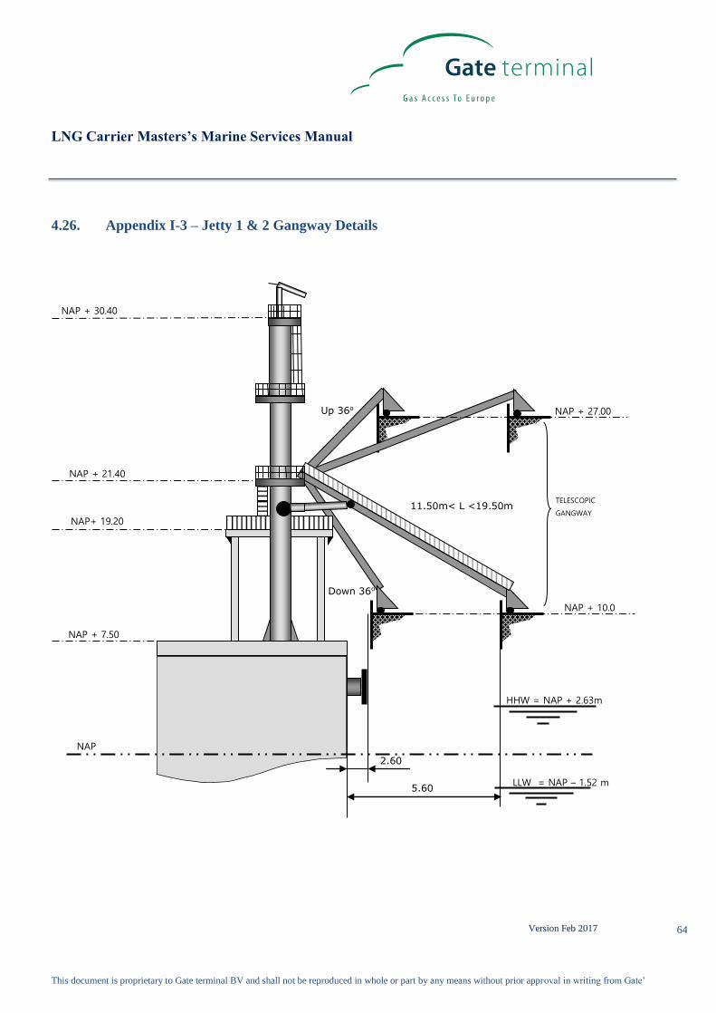
LNG Carrier Masters’s Marine Services Manual
Version Feb 2017
This document is proprietary to Gate terminal BV and shall not be reproduced in whole or part by any means without prior approval in writing from Gate’
64
4.26. Appendix I-3 – Jetty 1 & 2 Gangway Details
Down 36o
11.50m< L <19.50m
Up 36o
2.60
5.60
HHW = NAP + 2.63m
LLW = NAP – 1.52 m
NAP
NAP + 10.0
NAP + 27.00
NAP + 30.40
NAP + 7.50
NAP+ 19.20
NAP + 21.40
TELESCOPIC
GANGWAY

LNG Carrier Masters’s Marine Services Manual
Version Feb 2017
This document is proprietary to Gate terminal BV and shall not be reproduced in whole or part by any means without prior approval in writing from Gate’
65
4.27. Appendix I-4a – Jetty 1 & 2 Manifold Flange Details (16 inch ANSI B16.5)

LNG Carrier Masters’s Marine Services Manual
Version Feb 2017
This document is proprietary to Gate terminal BV and shall not be reproduced in whole or part by any means without prior approval in writing from Gate’
66
ANSI/ASME B16.5 – 2009 Paragraph 6.4.5.3
Either a serrated concentric or serrated spiral finish having a resultant surface finish
from 3.2 to 6.3 μm (125 to 250 μin.) average roughness shall be furnished. The cutting tool employed should have an
approximate 1.5mm (0.06 in.) or larger radius, and there should be from 1.8 grooves/mm through 2.2 grooves/mm (45
grooves/in. through 55 grooves/in.)

LNG Carrier Masters’s Marine Services Manual
Version Feb 2017
This document is proprietary to Gate terminal BV and shall not be reproduced in whole or part by any means without prior approval in writing from Gate’
67
4.28. Appendix I-4b – Flange Details (10 inch ANSI B16.5)

LNG Carrier Masters’s Marine Services Manual
Version Feb 2017
This document is proprietary to Gate terminal BV and shall not be reproduced in whole or part by any means without prior approval in writing from Gate’
68
4.29. Appendix I-5a – Jetty 1 & 2 (Un)loading Arm Details

LNG Carrier Masters’s Marine Services Manual
Version Feb 2017
This document is proprietary to Gate terminal BV and shall not be reproduced in whole or part by any means without prior approval in writing from Gate’
69
4.30. Appendix I-5b Jetty 3 (Un)loading Arm Details

LNG Carrier Masters’s Marine Services Manual
Version Feb 2017
This document is proprietary to Gate terminal BV and shall not be reproduced in whole or part by any means without prior approval in writing from Gate’
70
4.31. Appendix I-6a – Jetty 1 & 2 Cargo Arm Operating Envelope

LNG Carrier Masters’s Marine Services Manual
Version Feb 2017
This document is proprietary to Gate terminal BV and shall not be reproduced in whole or part by any means without prior approval in writing from Gate’
71
4.32. Appendix I-6b – Jetty 3 Cargo Arm Operating Envelope
Arms 37-J-01-B & C, manifold 300mm South
of spotting line
Arms 37-J-01-A & B, manifold 2500mm North Arms 37-J-01-A & C, manifold at spotting line
of spotting line

LNG Carrier Masters’s Marine Services Manual
Version Feb 2017
This document is proprietary to Gate terminal BV and shall not be reproduced in whole or part by any means without prior approval in writing from Gate’
72
4.33. Appendix Ja – Ship / Shore Communication Details
Pyle National Pin and Signal Data
Seatechnik provides both fibre optic and the 37 pin Pyle National electric cable.
Fibre optic cable reel (50 meters) and 6 way shore side connector and receptacle compatible with Furukawa and Seatechnik
fibre optic systems.
37 pin Pyle National receptacle with 50 meter cable and compatible plug. Shore terminal will supply the umbilical cable.
System will conform to EN 1532 standard. Pyle National Shore PINS:
ESD (SHORE-SHIP): 13,14
ESD (SHIP-SHORE) ESD: 15,16;
Hotline phone 5,6
PABX TELEPHONE: 7,8,
Public Phone Standard 9-10 ;
ESDS Link Diagrams -
Fibre Optic
Pyle National 37 Pin Fibre Optic
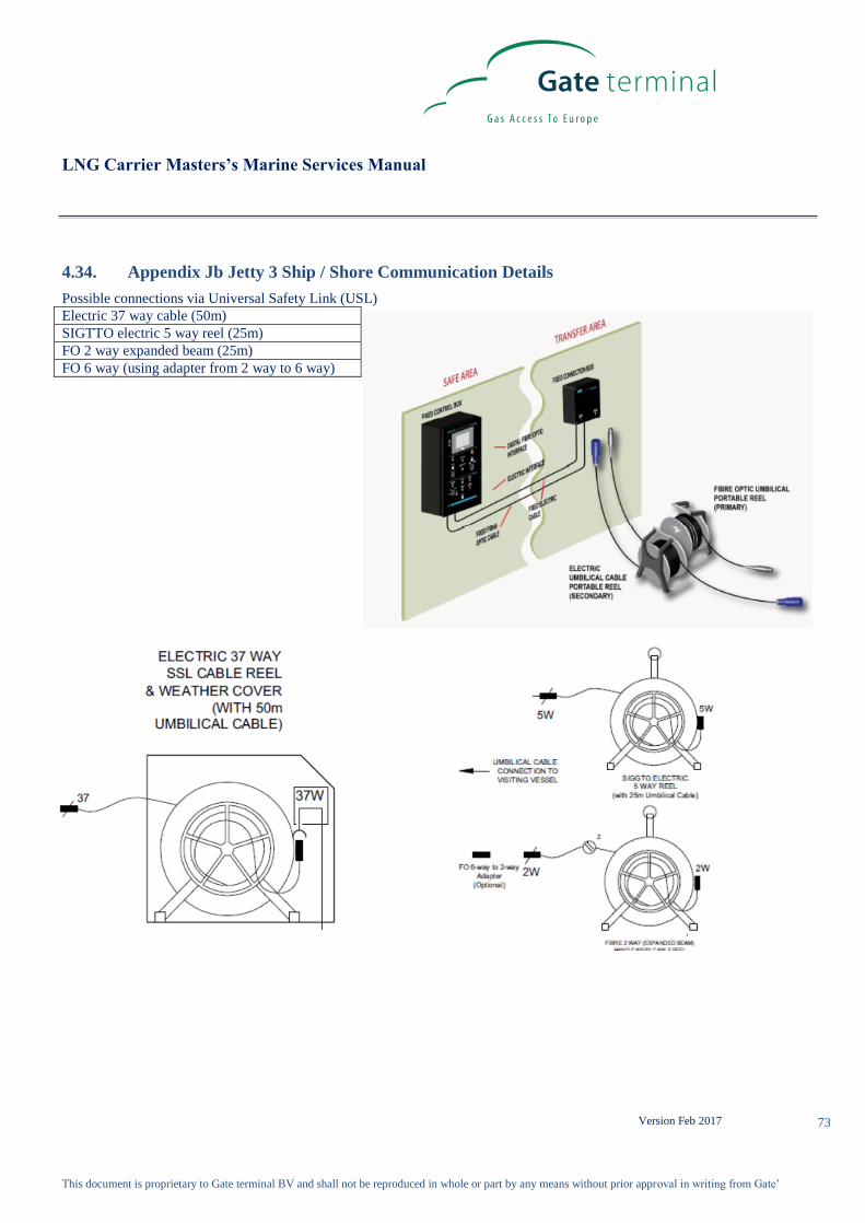
LNG Carrier Masters’s Marine Services Manual
Version Feb 2017
This document is proprietary to Gate terminal BV and shall not be reproduced in whole or part by any means without prior approval in writing from Gate’
73
4.34. Appendix Jb Jetty 3 Ship / Shore Communication Details
Possible connections via Universal Safety Link (USL)
Electric 37 way cable (50m)
SIGTTO electric 5 way reel (25m)
FO 2 way expanded beam (25m)
FO 6 way (using adapter from 2 way to 6 way)

LNG Carrier Masters’s Marine Services Manual
Version Feb 2017
This document is proprietary to Gate terminal BV and shall not be reproduced in whole or part by any means without prior approval in writing from Gate’
74
4.35. Appendix K – Pre Cargo Operations Meeting Discussion Checklist
1. Agree on needed adjustments to Laytime
2. Issue laptop with operating instructions
3. Verify communication channels and procedures to use
4. Discuss alarm settings
5. Agree on (un)loading rates and any required adjustments
6. Agree on cargo arm cool-down flow and pressure
7. Complete and Sign K1 – Ship / Shore Safety Checklist
8. Complete and Sign K2 – Safety Declaration
9. Complete and Sign K3 – LNG (Un)loading Agreement
10. Complete and Sign K4 – ISPS Declaration of Security
11. Complete and Sign K5 – Statement of compliance
12. LNGC will provide a “daily work plan” to identify Maintenance and repair issues.
13. Others as identified

LNG Carrier Masters’s Marine Services Manual
Version Feb 2017
This document is proprietary to Gate terminal BV and shall not be reproduced in whole or part by any means without prior approval in writing from Gate’
75
4.36. Appendix K1 – Ship / Shore Safety Checklist
Date of Arrival: ____________ Time of Arrival: ________
Berth: GATE LNG Jetty # Port: Rotterdam
Ship’s Name: _________________________
Instructions for completion:
The safety of operations requires that all questions and relevant statements are considered and the associated responsibility for
compliance are accepted, either jointly or singly by clearly ticking () the appropriate box. Where either party is not prepared
to accept assigned accountability, a comment must be made in the ‘remarks’ column and due consideration should be given to
assessing whether operations can proceed.
Where a particular item is considered not to be applicable to the ship, terminal or to the planned operation, a note to this effect
should be entered in the ‘remarks’ column.
Coding of Items
The presence of the letters A, P or R in the column entitled ‘Code’ indicates the following:
A (‘Agreement’). This indicates an agreement or procedure that should be identified in the ‘remarks’ column of the
check-list or communicated in some other mutually acceptable form.
P (‘Permission’). In the case of a negative answer to the statements coded ‘P’, operations should not be conducted
without written permission from the PoR authority.
R (‘Re-Check’). This indicates items to be re-checked at appropriate intervals as agreed between both parties at periods
stated in the declaration.
The joint declaration should not be signed until both parties have checked and accepted
their assigned responsibilities and accountabilities.

LNG Carrier Masters’s Marine Services Manual
Version Feb 2017
This document is proprietary to Gate terminal BV and shall not be reproduced in whole or part by any means without prior approval in writing from Gate’
76
Part ‘A’ – Bulk Liquid General – Physical Checks Bulk Liquid General Ship Terminal Code Remarks
1. There is safe access between ship and shore. R
2. The ship is securely moored. R
3. The agreed ship/shore communication system
is operative. A.R
System: Portophone
Backup System: Hotline + VHF 9
4. Emergency towing-off pennants are correctly
rigged and positioned and ready for immediate
use.
R
Propose to follow OCIMF
recommendation (Oct 2009) on
ETOPS
5. The ship’s fire hoses and fire-fighting
equipment is positioned and ready for
immediate use.
R
6. The terminal’s fire-fighting equipment is
positioned and ready for immediate use. R
7. The ship’s cargo and bunker hoses/pipelines
and manifolds are in good condition, properly
rigged and appropriate for the service
intended.
8. The terminal’s cargo and bunker hoses/arms
are in good condition, properly rigged and
appropriate for the service intended.
9. The cargo transfer system is sufficiently
isolated and drained to allow safe removal of
blank flanges prior to connection.
10. Scuppers and ‘save alls’ on board are
effectively plugged and drip trays are in
position and empty.
R
11. Temporarily removed scupper plugs will be
constantly monitored. R
12. Shore spill containment and sumps are
correctly managed.
13. The ship’s unused cargo and bunker
connections are properly secured with blank
flanges fully bolted.
14. The terminal’s unused cargo and bunker
connections are properly secured with blank
flanges fully bolted.
15. All cargo, ballast and bunker tank lids are closed

LNG Carrier Masters’s Marine Services Manual
Version Feb 2017
This document is proprietary to Gate terminal BV and shall not be reproduced in whole or part by any means without prior approval in writing from Gate’
77
16. Sea and overboard discharge valves, when
not in use, are closed and visibly secured.
17. All external doors, ports and windows in the
accommodation, stores and machinery
spaces are closed. Engine room vents may be
open.
R
18. The ship’s emergency fire control plans are
located externally.
Locations:
Question 19 – 20 (Inert Gas systems) are deleted because they are not applicable for
this terminal Part ‘B’ – Bulk Liquid General – Verbal Verification
Bulk Liquid – General Ship Terminal Code Remarks
21. The ship is ready to move under its own
power. P R
22. There is an effective deck watch in
attendance on board and adequate
supervision of operations on the ship and
in the terminal.
R
23. There are sufficient personnel on board to
deal with an emergency. R
24. The procedures for cargo and ballast
handling have been agreed A.R
See Appendix K3 LNG (Un)loading Agreement
25. The emergency signal and shutdown
procedure to be used by the ship and
shore have been explained and
understood.
A
Ship:
Shore: Slow whoop (3.5/0.5)
(see MMSM, Appendix G)
26. Material safety data sheets (MSDS) for
the cargo transfer have been exchanged
where requested.
P R
27. The hazards associated with toxic
components in the cargo being handled
have been identified.
H2S Content: NIL
Benzene Content: NIL
28. An International Shore Fire Connection
has been provided.
29. The agreed tank venting system will be
used. A R
Method:
Vapour return
30. The requirements for closed operations
have been agreed. R
31. The operation of the P/V system has been

LNG Carrier Masters’s Marine Services Manual
Version Feb 2017
This document is proprietary to Gate terminal BV and shall not be reproduced in whole or part by any means without prior approval in writing from Gate’
78
verified.
32. Where a vapour return line is connected,
operating parameters have been agreed. A R
50-250 mbarg (see MMSM 3.2)
33. Independent high level alarms, if fitted, are
operational and have been tested. A R
Ship: High Level:
High High Level:
34. Adequate electrical insulating means are
in place in the ship/shore connection. A R
Insulating flanges fitted on
cargo arms.
35. Shorelines are fitted with a non-return
valve or procedures to avoid ‘back filling’
have been discussed.
P R
36. Smoking areas have been identified and
requirements with regard to smoking are
observed.
A R
Nominated smoking areas:
See smoking notices
37. Naked light regulations are being
observed. A R
See MMSM 3.4.4
Use of naked lights is
prohibited
38. Ship/shore telephones, mobile phones and
pager requirements are being observed. A R
See MMSM 3.4.4
39. Hand torches (flashlights) are of an
approved type.
40. Fixed VHF/UHF transceivers and AIS
equipment are on the correct power mode
or switched off.
41. Portable VHF/UHF transceivers are of an
approved type.
42. The ship’s main radio transmitter aerials
are earthed and radars are switched off.
43. Electric cables to portable electrical
equipment within the hazardous area are
disconnected.
44. Window type air conditioning units are
disconnected.
45. Positive pressure is maintained inside the
accommodation and air conditioning
intakes, which may permit the entry of
cargo vapours, are closed
46. Measures have been taken to ensure
sufficient mechanical ventilation in the
pump room.
R

LNG Carrier Masters’s Marine Services Manual
Version Feb 2017
This document is proprietary to Gate terminal BV and shall not be reproduced in whole or part by any means without prior approval in writing from Gate’
79
47. There is provision for an emergency
escape.
48. The maximum wind and swell criteria for
operations has been agreed. A
Stop Cargo @: 17-20 m/s
Disconnect @: 21 m/s
Unberth @: Advise PoR
See MMSM Appendix A
49. Security protocols have been agreed
between the Ship Security Officer and
the Port Facility Security Officer, if
appropriate
A
Shore ISPS Level:
Ship ISPS Level:
D.o.S. YES/NO
50. Where appropriate, procedures have been
agreed for receiving nitrogen supplied
from shore, either for inerting or purging
ship’s tanks, or for line clearing into the ship
A P
N2 only for line clearing
Questions 51 – 61 and Part ‘C’ Bulk Liquid Chemicals – Verbal Verification are deleted because
they are not applicable for this terminal
Part ‘D’ – Bulk Liquefied Gases – Verbal Verification
Bulk Liquefied Gases Ship Terminal Code Remarks
1. Material Safety Data Sheets are available,
providing the necessary data for the safe
handling of cargo.
2. A manufacturer’s inhibition certificate,
where applicable, has been provided. P
3. The water spray system is ready for
immediate use.
4. There is sufficient protective equipment
(including self-contained breathing
apparatus) and protective clothing ready for
immediate use.
5. Hold and inter-barrier spaces are properly
inerted or filled with dry air, as required.
6. All remote control valves are in working
order.
7. The required cargo pumps and
compressors are in good working order,
and the maximum working pressures
have been agreed between ship and shore.
A
Max 10 barg on manifold
8. Re-liquefaction or boil off control
equipment is in good working order.

LNG Carrier Masters’s Marine Services Manual
Version Feb 2017
This document is proprietary to Gate terminal BV and shall not be reproduced in whole or part by any means without prior approval in writing from Gate’
80
9. The gas detection equipment has been
properly set for the cargo, is calibrated,
has been tested and inspected and is in good order.
10. Cargo system gauges and alarms are
correctly set and in good order.
11. Emergency shutdown systems have
been tested and are working properly.
12. Ship and shore have informed each
other of the closing rate of ESD valves, automatic valves or similar devices.
A
Ship:
Shore ESD1: 23 – 59 sec
Shore ESD2: 5 sec
13. Information has been exchanged
between ship and shore on the
maximum/minimum temperatures/ pressures of the cargo to be handled.
A
Ship Min……. Max………
Shore: See MMSM 3.1, 3.10
and 3.12
14. Cargo tanks are protected against
inadvertent overfilling at all times while any cargo operations are in progress.
15. The compressor room is properly
ventilated; the electrical motor room is
properly pressurized and the alarm system is working.
16. Cargo tank relief valves are set correctly
and actual relief valve settings are
clearly visibly displayed. (Record settings below)
Cargo Tank Relief Valve Settings
Tank No 1 Tank No 2
Tank No 3 Tank No 4
Tank No 5 Tank No 6
Declaration We the undersigned have checked, where appropriate jointly, the items on this checklist and have satisfied ourselves that the
entries we have made are correct to the best of our knowledge.
We have also made arrangements to carry out the repetitive checks as necessary and agreed that those items with the letter ‘R’
in the column ‘Code’ not supplemented by number in the check-list should be re-checked at intervals not exceeding 4 hours
(twice a shift).
For Ship For Shore
Name:
Name:

LNG Carrier Masters’s Marine Services Manual
Version Feb 2017
This document is proprietary to Gate terminal BV and shall not be reproduced in whole or part by any means without prior approval in writing from Gate’
81
Rank:
Rank:
Signature:
Signature:
Date: Time: Date: Time:

LNG Carrier Masters’s Marine Services Manual
Version Feb 2017
This document is proprietary to Gate terminal BV and shall not be reproduced in whole or part by any means without prior approval in writing from Gate’
82
REPEAT CHECKS DURING CARGO OPERATIONS
1. There is a safe access between the ship and shore.
2. The ship is securely moored.
3. The agreed ship/shore communication system is operative.
4. The ships fire hoses and fire-fighting equipment are positioned and ready for immediate use.
5. The terminal’s fire-fighting equipment are positioned and ready for immediate use.
6. Scuppers and save-alls on board are effectively plugged and drip trays are in position and empty.
7. Temporarily removed scupper plugs will be constantly monitored.
8. Shore spill containment and sumps are correctly managed.
9. All external doors, ports and windows in the accommodation, stores and machinery spaces are closed.
Engine room vents may be open.
10. The ship is ready to move under its own power.
11. There is an effective deck watch in attendance on board and adequate supervision of operations on the
ships and in the terminal.
12. There are sufficient personnel on board to deal with an emergency.
13. Agreed tank venting system is being used.
14. The requirements for closed operations are being observed.
15. Operating parameters of vapour return line are being observed.
16. Independent high level alarms are still in operation.
17. Electrical insulation in place at the ship/shore connection.
18. Smoking regulations are being observed.
19. Naked light regulations are being observed.
20. Ship/shore telephones, mobile phones and pager requirements are being observed.
21. Measures taken to ensure sufficient mechanical ventilation in the pump room.

LNG Carrier Masters’s Marine Services Manual
Version Feb 2017
This document is proprietary to Gate terminal BV and shall not be reproduced in whole or part by any means without prior approval in writing from Gate’
83
Record of Repetitive Checks
Date
Time
Initials
Ship
Initials
Shore
Date
Time
Initials
Ship
Initials
Shore
Date
Time
Initials
Ship
Initials
Shore

LNG Carrier Masters’s Marine Services Manual
Version Feb 2017
This document is proprietary to Gate terminal BV and shall not be reproduced in whole or part by any means without prior approval in writing from Gate’
84
Terminal / Vessel satisfaction sheet
The Berth area was visually inspected after completion of cargo (un)loading, securing of all Terminal cargo arms and Ship’s
(un)loading lines. The Berth and Ship were found to be free of pollution unless otherwise noted:
_____________________________________________________________________________________________________
_____________________________________________________________________________________________________
_____________________________________________________________________________________________________
_____________________________________________________________________________________________________
_____________________________________________________________________________________________________
Ship Shore
Good Average Good Average
Safety / security awareness
Pre-transfer meeting
Communications to / from terminal
English skills
Gangway access and guidance
Vessel moorings
Cargo operations
Ship / shore cooperation
Other (comments below)
For Ship For Shore
Name:
Name:
Rank:
Position:
Signature
Signature
Date:
Time:
Date:
Time:
In addition, after the vessel has departed the berth, a visual inspection shall be made of all fenders and mooring equipment. Any defects
found shall be reported to the vessel, her agent and owners.

LNG Carrier Masters’s Marine Services Manual
Version Feb 2017
This document is proprietary to Gate terminal BV and shall not be reproduced in whole or part by any means without prior approval in writing from Gate’
85
4.37. Appendix K2 – Safety Declaration
Terminal: Gate LNG Date: ___________
The Master SS/MV ________________ Port of Rotterdam, The Netherlands
Dear Sir,
Responsibility for the safe conduct of operations whilst your ship is at this terminal rests jointly with you, as master of the ship,
and with the responsible terminal representative. We wish, therefore, before operations start, to seek your full co-operation and
understanding on the safety requirements set out in the Ship/Shore Safety Check List which are based on safe practices widely
accepted by oil, gas and the tanker industries.
We expect you, and all under your command, to adhere strictly to these requirements throughout your stay alongside this
terminal and we, for our part, will ensure that our personnel do likewise, and co-operate fully with you in the mutual interest of
safe and efficient operations.
Before the start of operations, and from time to time thereafter for our mutual safety, a member of the terminal staff, where
appropriate together with a responsible officer, will make a routine inspection of your ship to ensure that the questions on the
Ship/Shore Safety Check List can be answered in the affirmative. Where corrective action is needed we will not agree to
operations commencing or, should they have been started, we will require them to be stopped.
Similarly, if you consider safety is endangered by any action on the part of our staff or by any equipment under our control
you should demand immediate cessation of operations.
THERE CAN BE NO COMPROMISE WITH SAFETY
Please acknowledge receipt of this letter by countersigning and returning the attached copy.
Signed: _________________________ Signed: ________________________
Terminal Representative Master / Chief Officer
Terminal Representative on Duty is: SS/MV_________________________
______________________________
Position or Title:__________________
Telephone No.: __________________
UHF/VHF Channel: _______________
Date: _____________ Time: ___________

LNG Carrier Masters’s Marine Services Manual
Version Feb 2017
This document is proprietary to Gate terminal BV and shall not be reproduced in whole or part by any means without prior approval in writing from Gate’
86
4.38. Appendix K3 – LNG (Un)loading Agreement
Date: _________ Time of All Fast: _________
Berth: Gate LNG Port: Rotterdam
Ship’s Name: _________________________
The events listed below are to be agreed to by the Terminal and Ship
1) Steam off main Engines at: _______ Arms can be brought aboard and connected.
2) Terminal to provide Hot line, phone, and portable UHF communications and instruct the Ship in their use.
3) Terminal to provide laptop computer for monitoring mooring line tension displays and weather information and
instruct the Ship in their use.
4) Vapour arm to be inerted with nitrogen until 2% or less Oxygen is achieved and leak tested at 1.5 Barg with soap
solution.
5) Liquid arms to be inerted with nitrogen until 2% or less Oxygen is achieved and then leak tested at the ship/shore
flange connection to 5-6 Barg with soap solution.
6). Initial cargo gauging to be done in accordance with Ships Custody Transfer Manual and calculations to be made as
per Throughput Agreement. The Terminal will witness the gauging and the Independent Marine Surveyor will certify
the results.
7). Ship’s vapour valve may be opened immediately after gauging
8) Warm ESD test to be carried out from Terminal and Ship. Ship activated ESD tested first
9) Liquid arms to be cooled-down, approximately 60 minutes in duration. Ship to adjust cool-down line pressure at
Terminals directions.
10). Cold ESD test to be carried out between terminal and Ship
11) Cargo pumps started at mutual request. Notify each other of each start time and the pump started.
12) Return vapour is free flowed from the Terminals storage tanks. Ship to control return vapour pressure.
13) Notify each other of the time of full cargo rate. Rate estimated at _________ m3/hour
14) Ship to notify Terminal of cargo aboard, rate and estimated completion time hourly.
15) Ship to notify Terminal one hour before ramping down cargo rate.
16) Notify each other of the time and designation of each pump that is shutdown.
17) Terminal to drain LNG cargo arms and inert with nitrogen until less than 2% methane by volume in a nitrogen
atmosphere is achieved.
18) Closing cargo gauging to be done in accordance with Ships Custody Transfer Manual and calculations to be made as
per GTC’s. The Terminal will witness the gauging and the Marine Surveyor will certify the results.
19) Terminal to inert Vapour arm with N2 until less than 2% methane by volume in a N2 atmosphere is achieved.
20) Terminal to disconnect liquid and vapour arms. Liquid strainers to be visually inspected and condition noted.
21) Terminal to install blinds on arms and manoeuvers to stowed position and secure.
22) Terminal to note time of arms clear. Ship can start main engine warm-up.
23) Ship to install blinds on its liquid and vapour arms.
For Ship
For Shore
Name:
Name:
Rank:
Rank:
Signature
Signature
Date:
Time:
Date:
Time:

LNG Carrier Masters’s Marine Services Manual
Version Feb 2017
This document is proprietary to Gate terminal BV and shall not be reproduced in whole or part by any means without prior approval in writing from Gate’
87
4.39. Appendix K4 – Declaration of Security
Name of Ship: __________________________________
Port of Registry: __________________________________
IMO Number: __________________________________
Name of Port Facility: Gate LNG
This Declaration of Security is valid from _________ until ___________ for the following activities:
LNG Ships’ storing via supply boat via Ship’s stores crane
LNG liquid and vapour hardarm connecting, purging, and cool-down
LNG cargo (un)loading
LNG liquid and vapour hardarm draining, purging, and disconnecting
LNG Ships’ preparations for unberthing and actual unberthing
Under the following security levels:
Security level(s) for the ship: ____________________________
Security level(s) for the port facility: ____________________________
The terminal facility and ship agree to the following security measures and responsibilities to ensure compliance with the
requirements of Part “A” of the International Code for the Security of Ships and of Port Facilities. The affixing of the initials of the GSO or SSO
under these columns indicates that the activity will
be done, in accordance with the relevant approved
plan, by:
Activity Gate Facility The Ship
Ensuring the performance of all security duties
Monitoring restricted areas to ensure that only authorized
personnel have access
Controlling access to the port facility
Controlling access to the ship
Monitoring of the port facility, including berthing areas and areas
surrounding the ship
Monitoring of the ship. Including berthing areas and areas
surrounding the ship
Handling of cargo
Delivery of ship’s stores
Handling unaccompanied baggage
Controlling the embarkation of persons and their effects

LNG Carrier Masters’s Marine Services Manual
Version Feb 2017
This document is proprietary to Gate terminal BV and shall not be reproduced in whole or part by any means without prior approval in writing from Gate’
88
Ensuring that security communication is readily available
between the ship and the port facility
The signatures to this agreement certify that security measures and arrangements for both the port facility and the ship during
the specified activities meet the provisions of Chapter XI-2 and Part “A” of the Code that will be implemented in accordance
with the provisions already stipulated in their approved plan or the specific arrangements agreed to and set out in the attached
Appendix ??
Dated: _____________________ on the _______________________
Signed for and on behalf of
Port Facility:
LNG Ship:
Signature of Port Facility Officer Signature of Master or Ship Security Officer
Name and title of person who signed
Name:
Name:
Title:
Title:
Contact Details Indicate telephone numbers or radio channels to be used
For the Port Facility
For the Ship
PFSO
Master
DPFSO
SSO
Company
CSO

LNG Carrier Masters’s Marine Services Manual
Version Feb 2017
This document is proprietary to Gate terminal BV and shall not be reproduced in whole or part by any means without prior approval in writing from Gate’
89
4.40. Appendix K5 – Statement of compliance Form
From the Master of M.V. /S.S: __________________ Date: _____________
To: Gate Terminal B.V.
As Master of the above named vessel, I acknowledge, for and on behalf of the owner, charterers and operators of the above
named vessel receipt of the latest version of the Masters Marine Service Manual of the Gate Terminal.
In consideration for permission to use the berths of the Terminal, I accept and agree to abide and be bound by all the
provisions of the Master Marine Service Manual of Gate.
For Ship For Terminal
Name:
Name:
Rank:
Position:
Signature
Signature
Date:
Time:
Date:
Time:

LNG Carrier Masters’s Marine Services Manual
Version Feb 2017
This document is proprietary to Gate terminal BV and shall not be reproduced in whole or part by any means without prior approval in writing from Gate’
90
4.41. Appendix K6 – ADN Checklist

LNG Carrier Masters’s Marine Services Manual
Version Feb 2017
This document is proprietary to Gate terminal BV and shall not be reproduced in whole or part by any means without prior approval in writing from Gate’
91

LNG Carrier Masters’s Marine Services Manual
Version Feb 2017
This document is proprietary to Gate terminal BV and shall not be reproduced in whole or part by any means without prior approval in writing from Gate’
92

LNG Carrier Masters’s Marine Services Manual
Version Feb 2017
This document is proprietary to Gate terminal BV and shall not be reproduced in whole or part by any means without prior approval in writing from Gate’
93
LNG Carrier Masters’s Marine Services Manual
Version Feb 2017
This document is proprietary to Gate terminal BV and shall not be reproduced in whole or part by any means without prior approval in writing from Gate’
94

LNG Carrier Masters’s Marine Services Manual
Version Feb 2017
This document is proprietary to Gate terminal BV and shall not be reproduced in whole or part by any means without prior approval in writing from Gate’
95

LNG Carrier Masters’s Marine Services Manual
Version Feb 2017
This document is proprietary to Gate terminal BV and shall not be reproduced in whole or part by any means without prior approval in writing from Gate’
96
4.42. Appendix L – Post Cargo Operations Meeting Checklist & Issues Documentation
Document / Discuss:
Terminal discharge issues that arose
LNG Carrier discharge issues that arose
Resources and Cost associated with any “Relocation Orders”
Agreement on the Certificate of Quality to be issued
Recommendations for process improvement
Estimated time before Gate issues “Ready to Retrieve Gangway” order
Status of any “Authorized Work” being done by the LNG Carrier
Status of any Crew that is ashore
Status of incoming LNG Carrier’s that may affect departure
Any anticipated delays by LNG Carrier to get underway
Weather, traffic or navigation issues for LNG Carrier departure