compax-m/s - motion control systems - a complete … · automation compax-m/s compact servo...
TRANSCRIPT

AutomationCOMPAX-M/SCOMPAX-M/SCOMPAX-M/SCOMPAX-M/SCompact Servo Contro ler
Catalogue 192-040011 N17 / UKVersion 17 / November 2000

192-040011 N17COMPAX compact servo controller
Automation2 Parker Hannifin GmbH
Electromechanical Division

192-040011 N17COMPAX compact servo controller
Automation3 Parker Hannifin GmbH
Electromechanical Division
Contents
COMPAX compact servo contro l ler ...................................................4
COMPAX application examples...................................................................................... 5
COMPAX - modern control technology ......................................................................... 6
System features ............................................................................................................... 7
COMPAX - fami ly .........................................................................................8
COMPAX 1000SL.............................................................................................................. 8
COMPAX 25XXS............................................................................................................... 9
COMPAX 45XXS/85XXS................................................................................................. 10
COMPAX-M..................................................................................................................... 11
COMPAX 35XXM ............................................................................................................ 13
Accessor ies / opt ions ............................................................................14
Software tools ................................................................................................................ 14
Operating panels............................................................................................................ 14
Hand-held terminal ........................................................................................................ 14
HEDA interface (Option A1/A4).................................................................................... 14
Parker servomotors ....................................................................................................... 14
EMC measures ............................................................................................15
AC surge filter ................................................................................................................ 15
Motor output filter .......................................................................................................... 16
External ballast resistors .............................................................................................. 17
COMPAX sof tware var iants ..................................................................18
COMPAX XX30: round table control............................................................................. 18
COMPAX XX50: synchronous cycle control................................................................ 19
COMPAX XX60: electronic gearbox ............................................................................. 20
COMPAX XX70: electronic cam control ....................................................................... 21
Technica l data ............................................................................................25
COMPAX order code ................................................................................28
Order code for accessor ies .................................................................29

192-040011 N17COMPAX compact servo controller
Automation4 Parker Hannifin GmbH
Electromechanical Division
COMPAX compact servo controller- Positioning control and servo amplifier in one unit -
The COMPAX family
The COMPAX compactservo controller ...integrates the following functionsinto one single device:• Operation of synchronous and
asynchronous motors.• Operation of 3-phase synchro-
nous linear motors.• Control of motion and peripherals• Closed loop control of speed /
power / position.• Power output stages:
1.0kW to 35kW• Communication via several in-
terfaces• Power input:
• from central power unit, or• directly from 230V AC or up to
500V AC• Program memory with 250 data
locationsThe hardware does not need to bechanged when using different mo-tor types - digitally set parametervalues are simply re-programmed.
Typical fields of applica-tion ...Examples of the applications forthis advanced technology are:• Assembly systems e.g. rotary
tables, continuous assemblyconveyors
• Special-purpose machinese.g. dosing units, electronicgearboxes
• Handling systems e.g. palet-tising, feeding, removal
• Machine tools e.g. tool posi-tioning, synchronous machining,tool drive
• Textile machines e.g. materialcovering, cutting & sewing
• Packaging machines e.g.roller feed, electronic cams,main drives
• Production machinery e.g.flying saws, coiling, rotatingcutters
• Measuring and testing e.g.sensor positioning, continuouspath control.
The control technology...of COMPAX compact servocontrol units offer the followingadvantages over separatehardware for position, speedand torque control:• rapid, simple and safe pa-
rameter setting and start-up• fast and stable control direct
from the factory• low peak torque requirements
and better tracking character-istics (reduced following error)
• only two independent optimi-sation parameters for the threecontrol loops
• central digital control of allcomponents from the poweroutput stage to the set pointgenerator
• less cabling with reduced sus-ceptibility to faults.
COMPAX 25XXS1*230V AC /3*230V AC2.5kW / 5kW6.3A / 12.6A
Mains power moduleNMD10: Up to 3*500V AC • 10kW / 20kWNMD20: Up to 3*500V AC • 20kW / 40kW
COMPAX 35XXMUp to 3 * 500V AC35kW / 70kW50A / 100A
COMPAX 45XXSUp to 3 * 500V AC4.5kW / 9kW6.5A / 13.0A
COMPAX 85XXSUp to 3 * 500V AC8.5kW / 17kW12.5A / 25.0A
COMPAX P1XXM: 3.8kW / 5.9kW • 5.5A / 8.5ACOMPAX 02XXM: 4.5kW / 5.9kW • 6.5A / 8.5ACOMPAX 05XXM: 8kW / 11.8kW • 11.5A / 17ACOMPAX 15XXM: 17kW / 34kW • 25A / 50A
Nominal data / peak data
COMPAX 10XXSL1*230V AC1kW / 2kW2.5A / 5.0A
Subject to technical change. Data represents the technical status at the time of closing the press.

192-040011 N17COMPAX compact servo controller
Automation5 Parker Hannifin GmbH
Electromechanical Division
COMPAX application examples
Transverse stop adjustment in materialfeed
Gantry robots
Longitudinal stop adjustment Rolling out films
Angled beam saw Mark-related cutting to size
Processing while in motion Electronic cam control
perforating welding

192-040011 N17COMPAX compact servo controller
Automation6 Parker Hannifin GmbH
Electromechanical Division
COMPAX - modern control technology ...Equipment technology for decentralised motiontasksCOMPAX has access to all system-related parame-ters, such as motor type, intermediate circuit voltage,motor currents, external moment of inertias, outputstage temperature etc. Automatic control parametersetting and the application of progressive controlconcepts such as monitor control and adaptive con-trol are only possible once these parameters havebeen accessed. The information obtained by integra-ting motion control and the entire control system intoone unit is used for fine tuning between closed loopand open loop elements of the control system. Thisleads to increased dynamic performance and greaterstability with reduced peak currents and torques. Aspecial signal processor uses a cycle time of 100 mi-croseconds to ensure rapid closed loop control. As aresult, the drive unit has the best possible servocharacteristics with regard to dynamic performance,stiffness and the peak torque available.
Fast and stableis a perfect description of the guiding principle em-ployed in all Parker Hannifin, Electromechanical Divi-sion digital controllers. The intelligence of our con-trollers avoids the costly and time-consuming prob-lems often experienced when starting up and config-uring a servo drive. Users will find that the experi-ence and knowledge gained from 30 years of practi-cal work in the drive control field have been imple-mented in the hardware and software used in thedigital COMPAX servo controllers. Users no longerneed to have a lot of experience of control systems.Modern methods, such as monitor and adaptiveclosed loop control are used by Parker Hannifin,Electromechanical Division to continue improving theperformance and options available on servo-control-lers.
Automatic control parameter setting
All the data needed to set the controller, such asexternal moments of inertia, motor type, transmissionratio etc., is entered directly in the servo control unit.The intelligent servo control unit automatically cal-culates the optimum controller parameters. Whenfirst activated, all control loops operate in a fast andstable manner straight away. A large number of pa-rameters no longer have to be compared using aprocess intensive both in terms of time and practicalknowledge. The automatic control parameter settingprocess considerably reduces the number of control-ler parameters requiring setting.At the most, only two unrelated optimisation para-meters (damping / rigidity) still have to be adapted tothe relevant application.
Project planning and starting up a servo controlunit
- Motor type- Gearing data- Drive type- Minimum mass- Maximum mass
Positioning axisfully functional
POWER ON
Assembly and
and motorwiring of controller
Production of controller
Dimensioning of drive
Production of controller
Dimensioning of drive
POWER ON
Test run
axis fullyfunctional
control technology Conventional control technology
Drive data Drive data
Data flow forparametrization
Possibly:Adjustment to meet
special needs byoptimizing parameters
- Attenuation- Stiffness
Assembly and wiringConnection of test
instruments of control-ler and motor
Empirical adjustmentof control parameters
(P - I - D) drive oscillates,too soft,not robust enough
Excessivecontouring errorsor drive oscillates,too soft,not robust enough
Test run
Conversion of travel incre-ments to travel units
Empirical setting ofposition controller
(P)
Automaticparametrization
fast and stable
Digital closed loop controlPower, speed and position are controlled byCOMPAX in a totally digital manner. Digital signalprocessors (DSPs) impressively satisfy the require-ment for computing capacity needed for software al-gorithms. The DSP is the technically highly devel-oped, universal platform required to implement func-tions such as nominal value generation, synchronisa-tion, slip compensation, fine interpolation as well asrapid motion programs. The digital signal processorforms the "heart" and the "main switching unit" ofmodern servo control units. Increasing computingoutput and memory sizes ensure transparency forfuture trends and further developments.The Parker Hannifin, Electromechanical Division,has been implementing the flexible access peripheryfor over ten years using specific ASIC.Today, DSP and ASIC provide the conceptual basisfor the most efficient solution in terms of controlquality and the most favoured solution in terms cost.Other advantages of purely digital closed loop control:• no analogue operating element, i.e. no drift.• reproducible controller parameters, since these are
stored digitally.• customer-specific modifications can be made to the
software

192-040011 N17COMPAX compact servo controller
Automation7 Parker Hannifin GmbH
Electromechanical Division
System featuresThe benefitsWhen using integrated process control in the com-pact COMPAX servo control unit, the superordinateprocess control unit is relieved of all motion-relatedcontrol tasks. Many applications allow for standaloneoperation. Using compact servo control units re-duces the costs and complexity of superordinatecontrol systems. Considerable savings can be madein the cabling as well as the control cabinet. The ma-chine can be started up faster and in a considerablysimpler manner.
Open communicationParker Hannifin Electromechanical Division providesengagement of the servo control unit by all leadingfield bus systems. A motion bus as well as inputsand outputs also form part of the goods available, asdo visual display elements:• RS232 (interface for parameter setting and open
loop control).• HEDA – real time input bus• Interbus S• Profibus DP and FMS (supported by Simatic S7 –
module)• CAN bus / CANopen• CS31 - system bus• 16 (8) binary inputs and outputs for status and pro-
gram control• Universal programmable controller data interface
via binary inputs and outputs• 3-digit, 7-segment display for error and status in-
formation (not available with the COMPAX 1000SL)and LED status display
The control systemin the basic COMPAX unit is designed perfectly forthe technical control requirements of a servo axis.Special control commands are implemented in thevarious unit variants for synchroniser or gearboxfunctions.Up to 250 structured motion commands can besaved in the internal program memory. The openloop control of the program procedure can be influ-enced via serial interface or binary I/O's.The structure of the order commands has been keptsimple and is based on the well-known programminglanguage BASIC. Program control instructions, com-parator functions, setting / resetting outputs and mo-
tion-related commands for specifying the speed, po-sition, acceleration, etc. are all available. For moreinformation, see the following sample program:
1: ACCEL 250 Acceleration time 250ms2: SPEED 80 Velocity 80%3: P010=P040*2.75 Multiplication4: P005=P005/2 Division with parameter assign-
ment5: V002=P041+20 Addition with parameter6: V001=S1+17 Addition with status and variable
assignment7: REPEAT 10 Conditional wait loop 1s8: IF E7=1 GOTO 13 Check if input E7 is at logic 19: WAIT 100 Wait time 100ms10: END End of REPEAT loop11: OUTPUT A7=1 Set output; no positioning12: GOTO 1713: POSA 1250 Positioning14: OUTPUT A8=1 Turn on output A8 for 500 ms15: WAIT 50016: OUTPUT A8=017: END
All commands are processed in sequence (sequen-tial programming). Program implementation can bebroken off (interrupt) at any time via the "Break" sig-nal. The axis is braked using with deceleration timeset. The program can be continued from anotherpoint.
Position recordingRotational and linear synchronous and asynchro-nous motors are supported. The following systemsare used for position recording:• Resolver (standard).• Sine-cosine sensor (single turn; multi-turn)
Option S1 or with programmable reset route optionS2.
The following are also supported:• Linear servo motors with sine-cosine sensors com-
bined with Hall effect sensors for commutation(COMPAX – option S3).
If there are angle deviations between the motor andload (slip), the load position can also be recorded viaan external encoder for optional correction.

192-040011 N17COMPAX 1000SL
Automation8 Parker Hannifin GmbH
Electromechanical Division
COMPAX - familyHousing technology:The housing and heat sink are designed to prevent the following 3 major problems occurring in the servo driveand control system.♦ The fully-enclosed metal housing provides shielding against electromagnetic interference♦ The generously proportioned heat sink prevents overheating and increases service life♦ Large surface contact with the rear panel provides good high frequency grounding
COMPAX 1000SLConnector assignment
Fiel
dbus
InEn
code
r
Inpu
t / O
utpu
tR
esol
ver
Fiel
dbus
Out
Lim
it Sw
itch
24 V
DC
RDu
mp
H2H1
RS2
32X6
X5X1
3
X12
X17
X19
X2X1
X4X3
X14
X15
HED
A
Out
HED
A
In
Inpu
t+
-
L1N
PEU
VW
PE+
-
Mot
orB
rake
PE+
-
230
V A
C
COM
PAX
- SL
X7
X13 Encoder
X6 RS232
X7 OUTX5 IN
Bus-systems:
X19 Input/Output
X14/X15 HEDAX17
Initiators
X12 Resolver
X3 24V DCVoltage suppply
X4 Ballast-resistor
X1 Motor andmotor brake
X2 230V ACVoltage supply
Connection PE -
Output data
DeviceCOMPAX ..
Nominal cur-rent [Aeff]
Peak current[Aeff] <5s
Power[kVA]
10XXSL 2.5 5 1
Power supply (limit values)
• 1*100V AC-1*250V AC; 45-65HzTypical AC mains: 230V ±10%
Regeneration mode
• Storable energy: 660µF/17Ws• External ballast resistance: 100Ω / 60W continuous /
253W for >1s (10s cooling period)For external ballast resistors, refer to page 16.
Installation and dimensions
Fiel
dbus
InEn
code
r
Inpu
t / O
utpu
tRe
solv
erFi
eldb
us O
utLi
mit
Switc
h
24 V
DC
RD
ump
H2
H1
RS23
2X6
X5X1
3
X12
X17
X19
X2X1
X4X3
X14
X15
HEDA
O
utHE
DA
In
Inpu
t+
-
L1N
PEU
VW
PE+
-
Mot
orBr
ake
PE
230
V A
C
85
180
206,
5
145,5
197,
5
16
5
55 174
+-
CO
MPA
X - S
L
183
X7
Fastening: 3 M4 Allen screwsInstallation distance: 100mm

192-040011 N17COMPAX 25XXS
Automation9 Parker Hannifin GmbH
Electromechanical Division
COMPAX 25XXSConnector assignment
X6
Input
Output
Status
Value
+- Enter
Ready Error
RS 232
Test
Control
X8 X10
X9 X11
Number
X6 RS232
X10 digital input and output
X11 control
X8 input / output
X9 test
X12 resolver
X14 HEDAX16 absolute
X18 fan
X13 encoder
X15 HEDAX17 initiatoren
CO
MPA
X-S
Plan view:
X5 Bus systems IN
X7
X2
X3
X1
X4
F193.16 AT
PEL3L2L1
PE
NL
3 x
230V
AC
1 x
230V
AC
AC supply
+- 24V DC
supply
Bus systemsOUT
motor andmotor brake
-+
PEWVU
PEBB
-+
Ballastresistor
1234
12
12345678
123
X2/
X3/
X1/
X4/
230V AC
230V AC
230V
AC
L1
L2L3
max
. 230
V A
C +
10%
lin
e to
line
vol
tage
!
Output data
DeviceCOMPAX ..
Nominal cur-rent [Aeff]
Peak current[Aeff] <5s
Power[kVA]
at mains supply: 230V AC25XXS 6.3 12.6 2.5
Power supply (limit values)• 3*80V AC - 3*250V AC; 45 - 65 Hz
1*100V AC-1*250V AC; 45-65HzTypical AC mains: 1(3) * 230V ±10%
Regeneration mode
• Storable energy: 1100µF/27 Ws• External ballast resistance: 56Ω / 180W
For external ballast resistors, refer to page 16.
Installation and dimensionsThe two retaining plates supplied can optionally beattached onto the back or the heat sink side.
Side by side mountingThe left-hand side of the heat sink is fastened to theunit. This is fastened to a metal wall using 2 retainingplates.Status when delivered:
290
Status Number
X6
X8 X10
- + Enter
Ready Error
RS232
Input
Output
Test
Control
X9 X11
Value
98130
270
240
1030
16
6565
221271
98
CO
MPA
X-S
Flat design by converting front flange mount-ingsThe left-hand side of the heat sink is fastened to theunit. It is fastened to a metal wall using 2 retainingplates.
S ta tu s N um be r
X6
X8 X10
- + E n ter
Ready E rror
RS232
In p u t
O u tp u t
Te st
C o n tro l
X9 X11
Value
186
270
240
290
1030
186
220
65
65
131181
17
95
CO
MPA
X-S
Fastening: 4 M6 Allen screwsInstallation distance: 135mm

192-040011 N17COMPAX 4500S / COMPAX 8500S
Automation10 Parker Hannifin GmbH
Electromechanical Division
COMPAX 45XXS/85XXSConnector assignment
X11X9
Input
Output Output
Input
Test Control
X10
X6
X8
RS232
Ready Error
ENTER+-
Value
Status Number
X9 test
X12 resolver
X16 absoluteX14 HEDA
X18 reserved
X11 Control
X6 RS232
output motor
X17 initiators
X13 encoder
DIGITAL
X15 HEDA
X8 digital input / output
X10 digital input / output
ext. supply
Plan view COMPAX 45XXS / 85XXS
HV
TD
L1
L2
L3
AC supply
Ballastresistor
X5 RS485 INX7 RS485 OUT
RD
X2
ConnexionPE 10mm2
Installation and dimensions
395
DIGITAL
24
378
351
77125
65
275325
11 65
Output data for individual units
DeviceCOMPAX ..
Nominal cur-rent [Aeff]
Peak current[Aeff] <5s
Power[kVA]
at mains supply: 400V AC45XXS 6.5 13.0 4.585XXS 12.5 25.0 8.6at mains supply: 460V AC45XXS 5.4 13.0 4.585XXS 10.5 25.0 8.6
Power supply (limit values)
• 3*80V AC - 3*500V AC; 45-65Hz.Typical AC mains: 400V ±10%; 460V ±10%; 480V ±5%.
Regeneration mode
• Storable energy:COMPAX 45XXS: 330µF / 52WsCOMPAX 85XXS: 500µF/80 Ws
• Internal ballast resistor: 300W continuous/3kW for<1s (20s cooling time).
• External ballast resistance: 22Ω/450WFor the external ballast resistors available, pleaserefer to page 16.
Fastening: 4 M5 Allen screwsInstallation distance: 135mm

192-040011 N17COMPAX-M
Automation11 Parker Hannifin GmbH
Electromechanical Division
COMPAX-M(COMPAX P1XXM, COMPAX 02XXM, COMPAX 05XXM, COMPAX 15XXM)
Connector assignment.
X2 intermediate loop power connections
X3 24V control voltage
X4 control- and status signals / bus signals or short circuit plug
X13 Encoder
COMPAX-M
X6
In pu t
O u tp u t
S ta tus
Value
+- E n te r
Ready E rro r
R S 2 3 2
Test
C o n tro l
X8 X10
X9 X11
N u m b e r
X1 motor
X5 control- andstatus- signal
bus-signalsinput
X6 RS232
X10 Input / Output
X11 Control
X8 Input / Output
X9 Test
X12 resolverX14 HEDA
X16 absolute encoder
X18 fan
X15 HEDAX17 initiators
Fan configuration:Units with fan: Units without fan:COMPAX P100M, COMPAX05XXM, COMPAX 15XXM
COMPAX 02XXM, NMD10,NMD20
Output data for individual unitsDeviceCOMPAX ..
Nominalcurrent[Aeff]
Peak current[Aeff] <5s
Power[kVA]
at mains supply: 400V ACP1XXM 5.5 8.5 3.802XXM 6.5 8.5 4.505XXM 11.5 17.0 8.015XXM 25.0 50.0 17.0at mains supply: 460V ACP1XXM 4.5 8.5 3.802XXM 5.4 8.5 4.505XXM 9.6 17.0 8.015XXM 21.0 50.0 17.0
Power supplyThe power is supplied via a central mains module;NMD10 or NMD20 (refer to page 12).With the component EAM5/01, available as an ac-cessory, DC voltage can be supplied:Input voltage range: 100V DC – 650V DC.When in regeneration mode, the DC bus voltagemust be limited to 750V DC.
Installation / dimensionsDirect wall installation
31
857550
10 40
450
430
364
50
390340
9665Attach with four 6-mm
hex-socket-head-screws
S ta tu s N um ber
X6
X8 X10
- + Enter
Ready E rro r
RS232
Input
Output
Test
Control
X9 X11
Value
DIGITAL
6049
10 40
450
430
364
02XXM, 05XXM,15XXM, NMD10
& NMD20
P1XXM
COMPAX-M
DIGITAL
S ta tus Number
X8 X10
E n te r
Ready Error
RS232
In p u t
O u tpu t
T est
C o ntro l
Value
COMPAX-M
Attach with two 6-mmhex-socket-head-screws
65
Installation distance: 86mm / 61mm
Indirect wall installation (not for COMPAXP100M)
50
5082
424
408
S ta tu s N um b er
X6
X8 X10
- + E n ter
Ready E rro r
RS232
In p u t
O u tp u t
T est
C on tro l
X9 X11
Value
DIGITAL
50
441,
542
4
8550
COMPAX-M
294244 96
mountingplate
mountingplate
For the angle required, please refer to designationMST2.

192-040011 N17NMD mains module
Automation12 Parker Hannifin GmbH
Electromechanical Division
Central mains power moduleOne mains power module can supply a number ofCOMPAX-M controllers (up to type 15XXM) with dif-ferent power ratings. The total load must not exceedthe rating of the mains power module. The total loadis calculated from the number of axes running simul-taneously and their respective power outputs. Itshould be noted here that not all axes will normallybe running simultaneously at rated torque and ratedspeed.The following functions are contained within themains power module:
• AC surge filter• Ballast resistors• A separate external supply is required for the 24V
DC control voltage.
The power voltage and the auxiliary voltage are sup-plied from the mains power module. The bus con-nection for the DC power, for the 24V auxiliary volt-age and an internal bus connection for control signalsrun on the top front model side.
View and assignment ofmains modules NMD10 and NMD20
L1 L2 L3 PE 24VPE + -
X1
X2
X3
X4
24V+
-
+
-24V
PE
+LS
-LS
PE
+LS
-LS
X6
Ready Error
X7
IN OUTRS 485
X8
Control
Power Supply
X8 Control
X7 bus-systems OUT
X4 control- and status-signals Bus signals continuation
X3 control voltage 24 V
X2 power inter- mediate loop
voltage supply 3*(80-500)V AC/X1 24V CC
X6 bus-systems IN
X18 fan
Technical data• Creates DC power for direct-on-line operation
(560V DC from 3 x 400V AC).
CE conformity
• EMC susceptibility/emissions in accordance withEN61800-3.
• Safety: VDE 0160/EN 50178.Output rating
Nominal out-put
Peak output
NMD10: 10 kW 20 kW (<3s)NMD20: 20 kW 40 kW (<3s)
Mains supply fuse protection• NMD10/NMD20: 20A/35A K circuit breaker or
16A/35A Neozed conventional fuse.Mains power• Nominal 3x400V AC +10% -15% • 45Hz – 65Hz• Range 80V AC - 500V AC •••• All mains configurations may
be usedTypical AC mains: 400V ±10%; 460V ±10%;480V ±5%
Control voltage• 24V DC ±10% •••• Fuse protection: 16A •••• Ripple:
<1Vp-p
Ready contact: 0.5A; 60V; 30W.
Thermal protection• 85°C heat sink temperature triggers an emergency
stop; the Ready contact drops out.Overvoltage limitation• Energy returned to the system during braking is
stored in the supply capacitors. The capacity andstorable energy is: 1100µF/173WsIf the energy returned causes overvoltage, the in-ternal power dump will turn on.
Regenerative powerrating
Lastsfor
Cooling downtime
NMD1017 kW <0.1s >10s2.8 kW <1s >20sWithout fan: 120W unlimitedWith fan: 250W unlimitedNMD2010 kW <0.1s >10s1.7 kW <1s >20sWithout fan: 120W unlimitedWith fan: 200W unlimited
External ballast resistors are available forNMD20 (refer to page 16).

192-040011 N17COMPAX 3500M
Automation13 Parker Hannifin GmbH
Electromechanical Division
COMPAX 35XXMConnector assignment
Digital
COMPAX-M
X5 X7
IN OUT
X19
Control
H1
X6
Inpu t
O utp u t
S ta tu s
Value
+- E n ter
Ready E rro r
R S 2 3 2
Test
C o n tro l
X8 X10
X9 X11
N u m b e r
X13 Encoder
X9 Test
X6 RS232X7 OUTX5 IN
Bussystems:
X19 Control X8/X10 In-/
Output
X11 ControlX14/X15 HEDA
X17 InitiatorsX16 Absolute encoder
X12 Resolver
Plan view
L1 L2 L3
PE
PE
PE+ -
U V W
PE
+ -
F1
Mains InputDC - In Braking
Motor
Motor
X 2024 V
X 21
Resistance
X 22 X 1
Brake
X 23
Motor
Spannungs-versorgungbis 500V AC
24V Steuer-spannung
externer Ballast-
widerstandMotor-Bremse
F1 3.16A
Output data
UnitCOMPAX ..
Nominal cur-rent [Aeff]
Peak current[Aeff] <5s
Power[kVA]
at mains supply: 400V AC35XXM 50.0 100.0 35.0at mains supply: 460V AC35XXM 42.0 100.0 35.0
Voltage supply range
• 3 x 250V – 3 x 500V AC; 45 - 65 Hz.Typical AC mains: 400V ±10%;460V ±10%; 480V ±5%
• Other COMPAX-M controllers can be linked se-quentially up to a rating of 15KW.
Mains supply fuse protection
62A K circuit breaker or suitable Neozed conventionalfuse.
Regeneration mode
• Storable energy: 3450µF/542 Ws• External ballast resistance: 10Ω / 2kW
For external ballast resistors, refer to page 16.
Installation / dimensionsFastening: 4 M6 Allen screws
390340
86
6565
218190
450
363
190
430
10 14
38
Digital
COMPAX-M
X5 X7
IN OUT
X19
Control
H1
X6
In p u t
O u tp u t
S ta tu s
Value
+- E nte r
Ready E rro r
R S 2 3 2
Test
C o n tro l
X8 X10
X9 X11
N u m b e r

192-040011 N17Accessories / options
Automation14 Parker Hannifin GmbH
Electromechanical Division
Accessories / optionsSoftware toolsThe ServoManager PC program is used to read, edit,print and file parameters and motion programs.The following functions are included:• convenient axis manager.• COMPAX configuration• downloading of COMPAX parameters• error tracking and error history• control of variables• direct terminal access to COMPAX
Operating panels(not for COMPAX 1000SL)The operating panel is available for front plate in-stallation or with the housing; it is used for controllingCOMPAX via the digital inputs.
Hand-held terminalThe BDF2/01 hand-held terminal is a convenientmenu-guided unit which canbe used to operate and con-figure COMPAX. The hand-held unit is connected toCOMPAX via the RS232 in-terface. It is therefore verywell suited to rapid diagnosisand for supporting start-up.The hand-held terminal of-fers the following functions:• displays any status value• menu-guided configuration• viewing and editing of pa-
rameters• viewing and editing pro-
grams• direct entry of commands
HEDA interface(Option A1/A4)
COMPAX-to-COMPAX interfaceFor COMPAX XX00, COMPAX XX60 andCOMPAX XX70.
HEDA synchronises several axes for simultaneousprocessing to a precision of ±2.5 microseconds.To do this, a COMPAX master (operating mode 1)transmits 2 synchronisation words to the slave axes(maximum 16) to enable synchronisation to occur.The slave axes (operating mode 2) are synchronisedautomatically. The master only transmits to one axisaddress.Application examples:• Connection of several axes to one encoder and
distribution of signals via HEDA.• Transferring the nominal position value or the ac-
tual position value from the master to the slaveaxes connected via HEDA.
• Coupling several cam profile generators using acommon time basea
• Applications with constantly-changing master
Interface between IPM and COMPAXXX00.To implement tracking and contouring tasks with theHAUSER interpolation module (IPM) for PCs and in-dustrial PCs.Communication occurs via the HEDA interface, arapid synchronous serial interface between the IPMand the COMPAX network.Functional scope of the IPM and COMPAX network:• Contours can be stored for up to 9 axes with up to
100 000 points• 16 (8 with the COMPAX 1000SL) datum-related
digital outputs.• Exchange of data between 9 axes within 1ms (set-
point values, auxiliary functions, position, lag error,speed, torque)
• Freedom to program all inputs and outputs• Internal native-language memory can still be used
to its full extent• Can be independently operated as a single axis
positioning system
Parker servomotorsThe following features are common to all motors:!Sinusoidal EMC !Standard flange ! IP 65 type of protection (IP 64 wave)! Integrated resolver/SinCos
! Class F insulation ! Peak torque up to three times nominal torque for maximum of 3 secondsFor more information, please request our motors catalogue (no. 192-060011).
BDF2 hand-heldterminal:
COMPAX
SHIFT
H1 H2
SHOK

192-040011 N17EMC measures
Automation15 Parker Hannifin GmbH
Electromechanical Division
EMC measuresAC surge filter
The following input filters may be used for RF suppression and/or for compliance withthe emission limit values as specified by EN61800-3.Type: NFI01/02
Type: NFI01/03
Dimension diagram:
6,6
ABC
DEFG
Ø 4
LINE
LOAD
Type: NFI01/04
30761
152
337320
356.
5
M5
25 400
347
LineNetzseite
LoadLastseite
10mm2
COMPAX 35XXM with sequentially mounted COMPAX-M controllers: Type: NFI01/05
LIN
E
LOA
D
110
±0.3
150
max
.
325 ±1 M1017Nm
6,5 x 15301 max.378 max. 81 max.
15
42
58
NMD10 / COMPAX45XXS / 85XXS
COMPAX 1000SL:(COMPAX 1000SL motor
cable > 50m
NMD20:
COMPAX 35XXM:
NFI01/02 NFI01/03A 177 240B 151 217C 70±0.3 115±0.3D 140 159E 125 145±0.5F 111 129G 65 64

192-040011 N17AC surge filter / motor output filter
Automation16 Parker Hannifin GmbH
Electromechanical Division
COMPAX 25XXS: motor cable >10mCOMPAX 10XXSL: motor cable <50m
COMPAX 25XXS: motor cable ≤≤≤≤10m
NFI01/01 Dimension diagram: NFI01/06 Dimension diagram:
50,8±0,385,4116139
79,5
101
88,9
±0,4
55,5
Ø 4
5,2 x 4
LINE
LOAD
66 max.91 max.
51 m
ax.
75 ±0.3
5,3L
NFASTON6,3 x 0,8
L'
N'
LIN
E
LOA
D
27
12
32 max.3,5
20
• Unshielded: <0.5m• Shielded: <5m
Motor output filterWe supply motor output filters for use with long motor leads (greater than 20m)
• Type: MDR01/01 16A / 2mH
• Type: MDR01/02 30A / 1.1mH
• Type: MDR01/03 >30A / 0.64mH
COMPAX 1000SL,COMPAX 25XXS:
Length of connec-tion between input
filter and unit:
Up to 16A nomi-nal motor current:
Up to 30A nomi-nal motor current:
Over 30A nominalmotor current:
MDR01/01 MDR01/02 MDR01/03A [mm] 150 180 205B [mm] 67 76 107D [mm] 113 136 157E [mm] 50 57 83F [mm] 6 6 7H [mm] 195 195 260I [mm] 95 110 150
Weight [kg] 4 6 17
ABI
FD E
H
U 1 V 1 W1 + - U 2 V 2 W2 + -

192-040011 N17External ballast resistors
Automation17 Parker Hannifin GmbH
Electromechanical Division
External ballast resistorsNMD20 with external ballast resistance of 15ΩΩΩΩ
Regenerative power rating Lasts for Cooling down timeBRM4/01: 0.57 kW unlimited
6.8 kW <1s >20s37 kW <0.4s >120s
BRM4/02: 0.74 kW unlimited8.9 kW 1s >20s37 kW <0.4s >120s
BRM4/03: 1.50 kW unlimited18 kW <1s >20s37 kW <0.4s >20s
COMPAX 25XXS with external ballast resistance of 56ΩΩΩΩRegenerative power rating Lasts for Cooling down timeBRM5/01: 180W unlimited
1 kW <1s >10s2.3 kW <0.4s ≥8s
COMPAX 45XXS/85XXS with external ballast resistance of 22ΩΩΩΩRegenerative power rating Lasts for Cooling down time BRM6/01: 450W unlimited
6.9 kW <1s >20s 28 kW <0.4s ≥120s
COMPAX 35XXM with external ballast resistance of 10ΩΩΩΩRegenerative power rating Lasts for Cooling down timeBRM7/01: 2.00 kW unlimited
56 kW <1s >100s17 kW <1s >10s
COMPAX 10XXSL with external ballast resistance of 100ΩΩΩΩRegenerative power rating Lasts for Cooling down timeBRM8/01: 60W unlimited
253W <1s ≥10s
Overloadingprotection
switch
95 97
96 98
AB
C
120
6,5
C
92
12
C
120
150
The ballast resistors are provided with a 1.5m connection lead. The maximumpermitted length is 2m.
protection againstcontact
∅∅∅∅ 5,8
222239 71
101
0.3m connection lead(max. 2m permitted)
6
7,5
40
2026240
225
0.25m connection lead.(max. 2m permitted)
Dimension diagram:BRM4, BRM6 and
BRM7
Dimension diagram:BRM5/01
Dimension dia-gram:BRM8/01
192-040011 N17Round table control
Automation18 Parker Hannifin GmbH
Electromechanical Division
COMPAX software variantsIn addition to the basic unit (COMPAX XX00) for general positioning tasks, software variants are alsoavailable for special applications:
Solutions are available for a wide range of applications by configuring a basic unit using add-on modules. Thismodular approach allows you to add or change hardware and software options to implement a solution tailoredexactly to your requirements. Each solution is therefore only based on standard hardware. The basic unit for allvariants is the COMPAX XX00M and this is used for general positioning tasks. The application-specific unitvariants can be distinguished from the basic unit by a numerical code which follows the COMPAX name. Thefirst two digits indicate the power of the output stage, the next two digits describe the application-specific vari-ants.
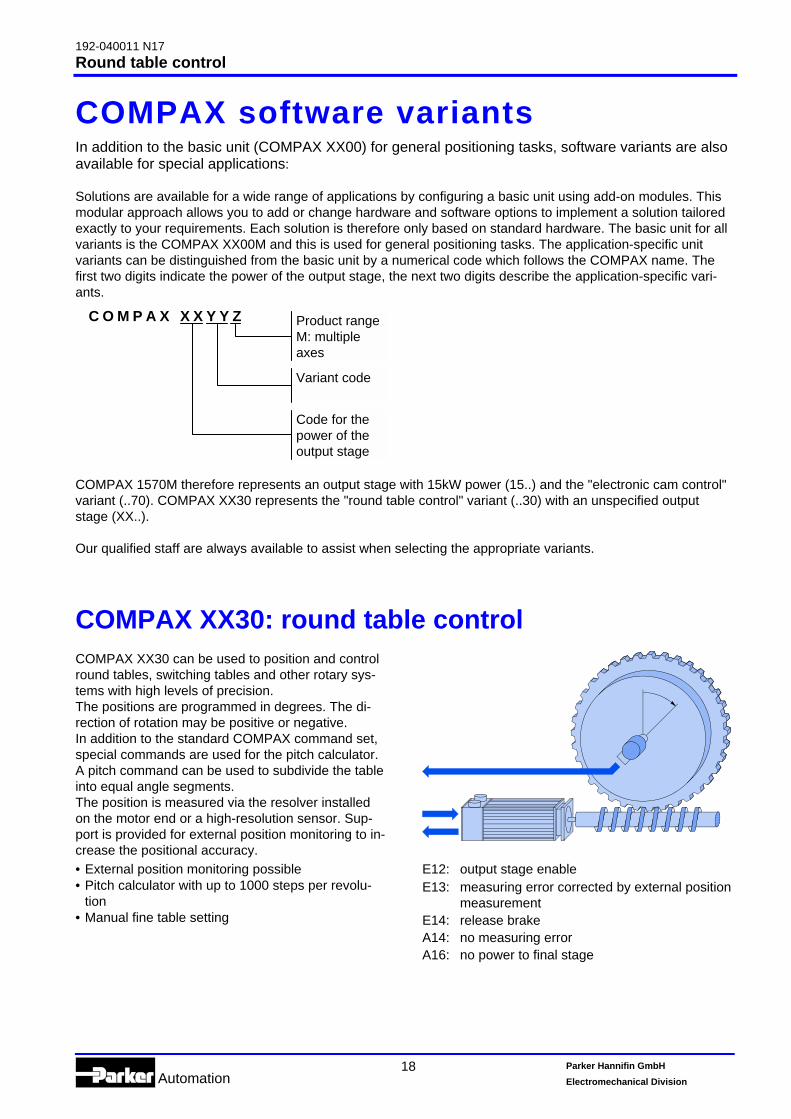
C O M P A X X X Y Y Z
COMPAX 1570M therefore represents an output stage with 15kW power (15..) and the "electronic cam control"variant (..70). COMPAX XX30 represents the "round table control" variant (..30) with an unspecified outputstage (XX..).
Our qualified staff are always available to assist when selecting the appropriate variants.
COMPAX XX30: round table controlCOMPAX XX30 can be used to position and controlround tables, switching tables and other rotary sys-tems with high levels of precision.The positions are programmed in degrees. The di-rection of rotation may be positive or negative.In addition to the standard COMPAX command set,special commands are used for the pitch calculator.A pitch command can be used to subdivide the tableinto equal angle segments.The position is measured via the resolver installedon the motor end or a high-resolution sensor. Sup-port is provided for external position monitoring to in-crease the positional accuracy.• External position monitoring possible• Pitch calculator with up to 1000 steps per revolu-
tion• Manual fine table setting
E12: output stage enableE13: measuring error corrected by external position
measurementE14: release brakeA14: no measuring errorA16: no power to final stage
Product rangeM: multipleaxes
Variant code
Code for thepower of theoutput stage

192-040011 N17Synchronous cycle control
Automation19 Parker Hannifin GmbH
Electromechanical Division
COMPAX XX50: synchronous cycle controlFunction not available with the COMPAX 1000SL! Implement this function with the electronic cam control.
Continuously driven saws and shears, con-tinuous processingA saw carriage is attached parallel to the direction ofmaterial flow. This is accelerated to the speed of thematerial to be processed and then travels at thesame speed as the material. If the relative speedbetween material and saw carriage is zero, synchro-nous running has been achieved. COMPAX will re-port this state via a digital output. Now the cuttingprocess is performed by running the cutting toolacross the direction of travel at right angles. Syn-chronous running is ended via a digital input and thecarriage stops. The carriage then moves automati-cally (or in a defined manner) to its initial position orto a predetermined position. The saw then waits untilthe material feed has travelled the distance corre-sponding to the cut length.
Angled beam sawA derivative of the continuously driven saw is the an-gled beam saw, used for wide materials. Here, thesaw guide (the linear axis) lies at a fixed angle abovethe material to be cut. The saw blade is at right an-gles to the direction of material travel. If the saw ismoved, this results in a saw movement in the direc-tion of material travel. This movement depends onthe angle between the saw guide and material. Thecontrol system uses the beam angle to calculate thesaw's feed speed so that synchronicity is set be-tween the saw blade and material. The relativespeed therefore becomes zero. Once the cuttingprocess is complete, the saw is raised and returnedto its waiting position.
Mark-related machining (registration)In some applications, the material feed is not con-tinuously measured but a measurement is takenwhenever a mark made on the material is reached.The longitudinal measurement then only begins oncethe mark has been detected and this has beencommunicated via a COMPAX input.
Reject length, chaff lengthWith increasing material speed, longer machiningtimes and decreasing cut lengths, the drive spendsincreasingly less time in the waiting position. If thiswaiting time approaches zero, then the control unitswitches to a substitute length, commonly known asthe reject length. COMPAX reports this state via anoutput. If compliance cannot be maintained with thereject length, which is normally greater than thestandard dimension, the control unit switches intochaff mode. This is the minimum length which can becut.
Manual cuttingWhen cutting manually, synchronisation is started di-rectly from the waiting position. In such instances,the specified length is not taken into account.
Head cut - initial machiningSpecial provision is made for handling the first syn-chronisation request after a START signal is re-ceived.
Material simulationDuring the start-up phase, when there is usually nomaterial available, the material speed can be simu-lated using a parameter or a potentiometer on theoverride input.
Further examples of machining processes whilein motion:
• stamping • filling • screwing • pouring • drilling
Special inputs and outputs:
E13:manual cuttingE14:mark signal validE15:end of synchronous travelE16:mark inputA14:synchronous comparatorA15:reject length too smallA16:reject length

192-040011 N17Electronic gearbox
Automation20 Parker Hannifin GmbH
Electromechanical Division
COMPAX XX60: electronic gearboxRange of application:Synchronous angle control, synchronous speedcontrol, processing while in motion.
Depending on the operating mode, COMPAX XX60can read and process an external master signal ei-ther as an alternative to or in conjunction with theinternal master. The external master signal can begenerated by:! an encoder on a master axis or! an encoder emulation from COMPAX and/or SV
drive, if these are controlling the master drive.It is recorded via an interface in COMPAX. The en-coder pulse assessment is set using parameters.This makes it possible to run a slave drive unit syn-chronously to the master unit. A ratio of 1:1, or a ra-tio in a large setting range (i>1 or i<1) can be se-lected via parameters. A negative prefix can be usedto signify reversed direction of rotation. COMPAXXX60 has two parameters for determining standardratio factors.The external master input can be controlled by tworeal time inputs (delay time 1ms). In addition to theenable input, which approves the external mastersignal for the controller, there is the option ofswitching between the two standard ratio factors.
Example:
Internal reference as dimensional refer-enceWhen the dimension reference is an internal refer-ence, the internal nominal value specifications areapplied to the datum point of the slave drive. Exter-nal command pulses are added to the current posi-tion as relative positioning. External nominal valuespecifications do not move the datum point.
absolute positioning to 100mmexternal reference value +70mmrelative positioning to +30mmabsolute positioning to 0mm
P0 P1 P2 P3! Absolute positioning to 100 mm (P1).! Approval of external nominal value (E16="1"). Unit
travels up to +70 mm in response to impulses froma command sensor (P2).
! Relative positioning by +30mm (P3)! Absolute command to datum point (P0)
Master position as dimensional refer-enceIf the dimensional reference is a master position, theinternal datum point of the slave drive is shifted bythe externally specified nominal value. The internalreference system is altered (can be corrected againby a reference journey).Superimposed movements are possible in this oper-ating mode. You can carry out positioning relative tothe master position. This can be used to undertakean internal machining program on a moved work-piece.
Absolutpositionierung auf 100mmExterner Sollwert +70mmRelativpositionierung um +30mmAbsolutpositionierung auf 0mm
P0 P0' P1 P2 P3
Clarification of this operating mode is provided in thefigure. This figure is based on the positioning cycleshown previously. Initially, the following axis is refer-enced to the internal datum point (P0). When theexternal nominal value is read, the datum point isshifted by the value specified.When using the absolute command for the datumpoint (POSA 0), the system is positioned to P0`. P0`is shifted by the value of the external positioningrelative to P0.The external nominal value can also be activatedduring an internal running move and the internal po-sitioning superimposed.Special inputs and outputs:E14:switching the dimensions reference to internal
reference or master position.E15:external switching of transmission factor.E16:engaging external nominal value.

192-040011 N17Electronic cam control
Automation21 Parker Hannifin GmbH
Electromechanical Division
COMPAX XX70: electronic cam control- M e c h a n i c a l c a m a n d c a m s h a f t f u n c t i o n i m p l e m e n t e d e l e c -
t r o n i c a l l y i n a s a f e a n d r e l i a b l e m a n n e r -
Table of motion co-ordinates
90
S1
180270
3600
Slave position
r
Cam plate
Cam disk
Slave positionRadius r =
Master angle
S2
Master angle
The field of application
• Using the COMPAX XX70 compact servo control-ler, mechanical cams and camshafts can be im-plemented electronically.
• The movement of the main axis is recorded by anincremental encoder. COMPAX XX70 generates thesetpoint of the slave axis according to the move-ment relationship requested and controls the driveaccordingly. The slave axis is implemented using a3-phase servo motor (either synchronous or asyn-chronous).
Typical fields of application can be found in thepackaging industry.Within a power range of 2.5kW - 35kW, theCOMPAX XX70 allows the drive power to be decen-tralised, thereby reducing:• space requirements• variety of parts required• mechanical coupling componentsThis results in:• smaller machines• reduction in cost• shorter set-up times• less expenditure on maintenance
The implementation
• The cam profile ......is stored in COMPAX XX70 as a sequence of ref-erence points in non-volatile memory and has thefollowing properties:• Up to 2500 reference points between which
COMPAX interpolates in a linear fashion• Repeatability: up to 0.02 degrees• Several profiles can be stored at the same time• Profiles can be selected externally• Dynamic switching between profiles using the "In-
terlink curves" function• The camshaft......is simulated using auxiliary functions which can beassigned to all reference points. COMPAX has thefollowing auxiliary functions:• Programmable control of 8 digital outputs. The ini-
tial pattern is set up when processing the first ref-erence point
• An analogue voltage is generated via 2 analogueoutputsA voltage in the range of ±10V is output dependingon the programmed auxiliary value and on the an-gle of the master axis.

192-040011 N17Electronic cam control
Automation22 Parker Hannifin GmbH
Electromechanical Division
Cam control functions
The primary taskThe control unit's primary task is to move a slaveaxis in accordance with the profile of motion pro-grammed by the user and depending on the angle ofthe master axis. Several slave axes with individuallyprogrammed profiles can be coupled to the masteraxis.
Slave
Master
Slave(length)
Master(angle)
90° 180° 270° 360°
Coupling and decoupling the slave axisThe slave axis can be coupled and decoupled inseveral ways.
Coupling and decoupling at standstill
The simplest way to initialise the axis is by perform-ing a homing routine after the power has been ap-plied. Once the system has been started externally,COMPAX automatically selects the cam requiredand is ready to follow the master axis. The masteraxis usually now starts its running move. The slaveaxis runs in accordance with the movement relation-ship entered.
Coupling and decoupling while master axis is ro-tating
The following options are available for coupling on arotating master axis:
• When the external "couple" control signal is re-ceived, the slave axis starts up, then moves downthe stored profile, starting from the programmedsynchronous position (MS). Decoupling occurs inthe same manner.
•
slav
e
mastercouplingsignal
MS
S0
When theexternal "couple" signal is received, the slave axisonly starts up once the master axis has also reachthe programmed coupling position (ME). The slaveaxis moves from the specified synchronous posi-tion and does so synchronously with the masteraxis. Decoupling occurs in the same manner, i.e.the slave axis at the decoupling position (MA) exitssynchronous mode and slows down at the brakingposition (MB) to come to rest at S0.
slav
e
master
S0
ME MScouplingsignal
The option of dynamic cam changeover alsoallows for the implementation of individualcoupling and decoupling operations.
Programmable cam cyclesYou can determine whether the slave axis shouldcontinually follow the master axis or whether thecoupling to the master axis should be ended after adefined number of cam cycles.
Lag warningYou can monitor the variation between the actualposition and the programmed profile by means of apreset "lag warning". COMPAX will generate an out-put signal whenever this value is exceeded.

192-040011 N17Electronic cam control
Automation23 Parker Hannifin GmbH
Electromechanical Division
Label synchronisationIn the packaging and printing industry, synchronisa-tion of a slave axis to printed labels is often neces-sary in order to compensate for material slip. If theslave position is adjusted by the amount of slip, cal-culated between product and label sensor, the errorcan be corrected until the next label appears.
Starting synchronisation
When the master is at a standstill
The slave is informed of the master's present posi-tion before the start. Recording of the master posi-tion is initiated by a control input.
When the master is moving
Targeted start of master position recording:a) Statically or dynamically via a control input.b) Via a control input in conjunction with the next
edge of the encoder index track.
c) Edge-triggered via a control input for a singlemaster cycle.Application:Asynchronous starting of a profile which must bereferenced to a product carried on a belt at regu-lar intervals.
Cam design serviceWhen working with applications for the COMPAXXX70 electronic cam generator, there is always theoption of having Hauser create all the necessaryprofile data.The Technical Support department will perform thistask as a service which is charged according to cost.A program called "Optimus Motus" is used as a soft-ware design tool. Depending on the application, thissoftware tool can be used to implement many differ-ent types of motion profile. This offers the possibilityof optimising the acceleration requirements of theapplication and therefore selecting the most eco-nomic motor/controller combination.
Example: Cam design using the "Optimus Motus" program

192-040011 N17Electronic cam control
Automation24 Parker Hannifin GmbH
Electromechanical Division
CamEditor for creating curves
All the 2500 available data records in the reference point memory may be assigned to a single profile or to anumber of profiles. Each reference point can generate an auxiliary function signal using the 8 digital and 2 ana-logue outputs.
Creating profilesYou can use the HAUSER CamEditor to create camprofiles. This is a Windows program and provides theadvantages of a Windows interface.
Profile input and creating the reference point ta-ble
You specify the fixed points which are essential tothe profile. The CamEditor takes these and uses aninterpolation process to create intermediate pointswhich reflect the required profile. The result is dis-played in graphic form as a position, speed and ac-celeration plot.
CamEditor may be used to assign auxiliary functionsto any reference point.
Fixpoints set point tablefor COMPAX
1. set point
2. set point
max. 2500set points
Calculation of the set points with the PC
Master Slave
0º
120º
130º
140º
0mm
10mm
15mm
17mm
145º 18mm
Menu for fixed point entry
Menu for auxiliary function entry
Linear cam diagram
Polar cam diagram
192-040011 N17Technical data
Automation25 Parker Hannifin GmbH
Electromechanical Division
Technical dataPower featuresFunctional capability
• Position, speed and current controller.• IGBT output stage protected from short circuits and
ground/earth faults.• Digital positioning controller.• Motion controller.
Supported motors & resolvers
• Sine-commuted synchronous motors up to a max.speed of 9000 rpm.
• Asynchronous motors.• Supported resolvers
• Litton:JSSBH-15-E-5JSSBH-21-P4RE-21-1-A05RE-15-1-B04
• Tamagawa: 2018N321 E64• Siemens: 23401-T2509-C202
• SinCos support (Stegmann).• 3 phase synchronous linear motors with:
• sine-cosine linear encoder (1Vss).• digital Hall sensor commutation (5V).
Output data for individual units
DeviceCOMPAX ..
Nominal cur-rent [Aeff]
Peak current[Aeff] <5s
Power[kVA]
at mains supply: 230V AC10XXSL 2.5 5.0 1.025XXS 6.3 12.6 2.5at mains supply: 400V AC45XXS 6.5 13.0 4.585XXS 12.5 25.0 8.6P1XXM 5.5 8.5 3.802XXM 6.5 8.5 4.505XXM 11.5 17.0 8.015XXM 25.0 50.0 17.035XXM 50.0 100.0 35.0at mains supply: 460V AC45XXS 5.4 13.0 4.585XXS 10.5 25.0 8.6P1XXM 4.5 8.5 3.802XXM 5.4 8.5 4.505XXM 9.6 17.0 8.015XXM 21.0 50.0 17.035XXM 42.0 100.0 35.0
CE conformity
• EMC susceptibility/emissions in accordance withEN61800-3.
• Safety: VDE 0160/EN 50178.
Voltage supply (limit values)
COMPAX-M (NMD)• 3*80V AC - 3*500V AC; 45-65Hz.COMPAX 35XXM• 3 x 250V – 3 x 500V AC; 45 - 65 Hz.COMPAX 25XXS• 3*80V AC - 3*250V AC; 45 - 65 Hz
1*100V AC-1*250V AC; 45-65HzCOMPAX 10XXSL• 1*100V AC-1*250V AC; 45-65HzCOMPAX 45XXS/85XXS• 3*80V AC - 3*500V AC; 45-65Hz.
Mains supply fuse protection
K circuit breaker or suitable Neozed conventionalfuse.• NMD (COMPAX-M)
NMD10: 16A (K circuit breaker: 20A)NMD20: 35A
• COMPAX 35XXM: 62A• COMPAX 25XXS: 1x230V AC: 16A
3*230V AC: 10A• COMPAX 10XXSL: 16A• COMPAX 45XXS/85XXS: 16A
DC bus voltage
• 300V DC with 3(1)x230V AC.• 560V DC of 3x400V AC supply.• 650V DC with 3x460V AC.
Output voltage to motor
Ignoring power losses, motor output rating is 86% ofthe AC supply voltage available
Braking operation
• Storable energy• NMD10/20: 1100µF / 173Ws• COMPAX 25XXS: 1000µF/27 Ws• COMPAX 45XXS: 330µF/52 Ws• COMPAX 85XXS: 500µF/80 Ws• COMPAX 1000SL: 660µF/17 Ws
• Ballast resistors (refer to page 16)

192-040011 N17Technical data
Automation26 Parker Hannifin GmbH
Electromechanical Division
Control voltage
• 24V DC ±10%, Ripple <1VSSCurrent required:• 1.3A for COMPAX 35XXM.• 1A for COMPAX 45XXS/85XXS.• 0.8A for the other units.• digital outputs, each 100 mA max.• if needed, for fan approx. 100 mA.• for motor holding brake (0.35A-1.6A).• if needed, absolute encoder: 0.3A.
Accuracy
• Positioning of the motor shaft:Resolution: 16 bits (= 0.3 minutes of angle)Absolute precision: +/-15 minutes of angle
Maximum power dissipation
• COMPAX 10XXSL: ...................... 50W• COMPAX P1XXM: ..................... 140W• COMPAX 02XXM / NMD10/20: . 120W• COMPAX 05/10/15XXM: ........... 250W• COMPAX 25XXS: ....................... 80W• COMPAX 45XXS/85XXS:.......... 170W• COMPAX 35XXM: ..................... 610W
Native-language memory
250 data records, protected from power failure.Data record functions• Positioning commands, I/O instructions, program
commands:ACCEL, SPEED, POSA, POSR, WAIT, GOTO,GOSUB, IF, OUTPUT, REPEAT, RETURN, END,WAIT START, GOTO EXT, GOSUB EXT, SPEEDSYNC, OUTPUT A0, GOTO, POSR SPEED, POSROUTPUT , +, -, *, /.
Target value generator
• Ramps: linear, quadr., smooth; 10ms...60s.• Travel specified in increments, mm, inch or variable
using a scaling factor.
Monitoring functions
• Mains power/auxiliary control voltage.• Motor and power stage temperature/locked-shaft
protection.• Lag error monitoring.• Ready contact: 0.5A; 60V; 30W.
Ambient conditions
• Temperature range: 0...45°C.• Max. relative air humidity in acc. with DIN 40040
class F (≤75%) non-condensing.
InterfacesControl inputs: 16 (8 for COMPAX 1000SL)
• 24V DC, 10 kOhm.
Control outputs: 16 (8 for COMPAX 1000SL)
• active HIGH, short circuit protected; 24V/100 mA.
RS 232
• 9600 Baud or 4800 Baud(for COMPAX 1000SL, fixed at 9600 Baud).
• Length of words 8 bits, 1 start bit, 1 stop bit.• Software handshake XON, XOFF.
Programmable controller data interface (not forCOMPAX 1000SL)
• Via 5 binary inputs and outputs.
Encoder interface (option; standard for COMPAX1000SL)
• Encoder emulation: 512 or 1024 counts/rev• Encoder input: RS422 interface; supply: 5V;
120-5000 lines/rev
COMPAX 1000SL signal interfaces (optional)
• Encoder emulation or• Encoder input or• Step/direction input or• Analogue input ± 10V
Absolute value sensor interface (option A1) (notfor COMPAX 1000SL)
• Supply voltage: 24V+/-10%.• Sensing code: grey code, single step.• Direction of counting: in clockwise direction when
looking at the shaft: rising.• Data interface: RS422 /24-bit data format (start:
MSB). • Cycle frequency: 100 kHz.
SinCos (option S1/S2/S3)
• High-resolution encoder instead of resolver.• Singleturn or Multiturn (absolute value over 4096
motor revolutions).• Option S2 with multiturn: absolute value sensor with
programmable transmission factor.• Option S3 for linear motors.
HEDA: synchron, serial real time interface
Included in option A4 or option A1.

192-040011 N17Technical data
Automation27 Parker Hannifin GmbH
Electromechanical Division
Bus connection optionsAll with opto-isolated bus link.
RS485
• Max. 115k Baud • 2 or 4 wire/RS485
Interbus S
• 2-conductor remote bus • 500 kBaud.• max. 64 participants per ring.
Profibus
• 1.5M Baud • Sinec L2-DP and FMS.
CS31
• COMPAX - ABB interface.
CANbus
• Up to 1.0MBaud • Basic CAN.• CAN protocol in acc. with specification 1.2.• Hardware in acc. with ISO/DIS 11898
CANopen
• Protocol in acc. with CiA DS 301.• Profile CiA DS 402 for drives.
OperationParameter input/status request
• Via COMPAX hand-held terminal.• Via RS232 and bus interface.• Via the programmable controller data interface (not
for COMPAX 1000SL).• Status query also via the 3-digit LED display on the
front plate (not for COMPAX 1000SL).
HousingHousing
• Fully-enclosed metal housing.• Insulation: VDE 0160/protection class IP20.• IP54 on request.
Connections
• Motor, power bus, control inputs & outputs via ter-minals.
• Sensor cables & interfaces via two-part connectors.
Installation
• Panel-mounting, suitable for installation in industrialcontrol cabinets.
Dimensions
• NMD/COMPAX-M: refer to page 11.• COMPAX 25XXS: refer to page 9.• COMPAX 10XXSL: refer to page 8.• COMPAX 45XXS/85XXS: refer to page 10.• Weights: COMPAX P1XXM: .............5.6 kg
COMPAX 10XXS: .............1.6 kgCOMPAX 25XXSL: ...........4.6 kgCOMPAX 45XXS/85XXS: ..6.5 kgCOMPAX 02XX:.................7.1 kgCOMPAX 05/15: ................7.8 kgCOMPAX 35XXM:............22.5 kgNMD10:..............................7.6 kgNMD20:..............................8.1 kg
Standard scope of supply• COMPAX with User Guide.• X8, X9, X10, X11 mating connectors.• ServoManager.
Mains power moduleFor technical data, please refer to page 12.
Permissible 3-phase mains powersuppliesThe units (COMPAX or NMD) can be operated on allmains configurations 1. Examples:
IT mains power supplies
TN mains power supplies
1When using Delta mains power sup-plies, note that CE requirements (lowvoltage guideline) are no longer satis-fied when the voltage between aphase and earth >300V AC (isolatedmeasurement voltage).
192-040011 N17Order code
Automation28 Parker Hannifin GmbH
Electromechanical Division
COMPAX order codeCOMPAX order code A / D / E / E / F / SCOMPAX-M performance class
3.8 kVA P 14.5 kVA 0 28.0 kVA 0 517.0 kVA 1 535.0 kVA 3 5
COMPAX-S(L) performance class1.0 kVA 1 02.5 kVA 2 54.5 kVA 4 58.6 kVA 8 5
VariantsStandard 0 0Round table control 3 0Synchronous cycle control (not for COMPAX 1000SL) 5 0Electronic gearbox 6 0Electronic cam control 7 0
Unit typeCOMPAX-M MCOMPAX-S (L) S
OptionsNo absolute value sensor / real time bus option requested 0
HEDA real time bus (incl. absolute value sensor module) (not for COMPAX1000SL)
1
HEDA real time bus for COMPAX 1000SL 4
D/A monitor option not requested 0D/A monitor (not for COMPAX 1000SL) 1
Encoder input option not requested (not for COMPAX 1000SL) 0Encoder input (with line terminator) (not for COMPAX 1000SL) 2Encoder input (without line terminator) (not for COMPAX 1000SL) 4Analogue speed specification (not for COMPAX 1000SL) 7
Encoder emulation option not requested 0Encoder emulation (not for COMPAX 1000SL) 3
Field bus option not requested 0RS 485 interface (4-wire) 1Interbus S interface 2Profibus 3CAN bus 4RS 485 interface (2-wire) 5CS31 protocol (ABB) 7CANopen 8
Sine-cosine option not requested 0Feedback module for high-resolution sensor 1Feedback module for high-resolution sensor – multiturn with programmable transmission factor 2Feedback module for linear motors 3
192-040011 N17Order code
Automation29 Parker Hannifin GmbH
Electromechanical Division
Order code for accessoriesOrder code /10kW mains power module (only in conjunction with COMPAX-M) N M D 1 0 / -- --20kW mains power module (only in conjunction with COMPAX-M) N M D 2 0 / -- --Monitor box for option D1 (D/A monitor) (not for COMPAX 1000SL) A S S 0 1 / 0 1Operating panel (without housing for front plate installation) (not for COMPAX 1000SL) B D F 0 1 / 0 2Operating panel (with housing) (not for COMPAX 1000SL) B D F 0 1 / 0 3Interface cable between operating panel and COMPAX (not for COMPAX 1000SL) S S K 0 6 / ... ... 1
User terminal with 1.5m cable B D F 0 2 / 0 1Ballast resistor for NMD20 (0.57 / 37kW) B R M 0 4 / 0 1Ballast resistance for NMD20 (0.74 / 37kW) B R M 0 4 / 0 2Ballast resistance for NMD20 (1.5 / 37kW) B R M 0 4 / 0 3Ballast resistance for COMPAX 25XXS (0.18 / 2.3kW) B R M 0 5 / 0 1Ballast resistance for COMPAX 45XXS / 85XXS (0.57 / 28kW) B R M 0 6 / 0 1Ballast resistance for COMPAX 35XXM (2.0 / 56kW) B R M 0 7 / 0 1Ballast resistance for COMPAX 10XXSL (60 / 253W) B R M 0 8 / 0 1AC surge filter for COMPAX 25XXS (motor cable >10m) or COMPAX 1000SL (< 50m motor cable) N F I 0 1 / 0 1AC surge filter for COMPAX 25XXS (< 10m motor cable) N F I 0 1 / 0 6AC surge filter for NMD10 / COMPAX 45/85XXS / COMPAX 1000SL (COMPAX 1000SL > 50m motor cable) N F I 0 1 / 0 2AC surge filter for NMD20 N F I 0 1 / 0 3AC surge filter for COMPAX 35XXM N F I 0 1 / 0 4AC surge filter for COMPAX 35XXM with sequentially mounted COMPAX-M N F I 0 1 / 0 5Motor output filter for up to 16A nominal motor current M D R 0 1 / 0 1Motor output filter for up to 30A nominal motor current M D R 0 1 / 0 2Motor output filter for over 30A nominal motor current M D R 0 1 / 0 3Installation set for indirect wall installation (refer to page 11) M T S 0 2 / 0 1Module for direct DC supply from COMPAX-M E A M 0 5 / 0 1Sensor cable between encoder and COMPAX G B K 1 1 / ... ... 1
Sensor cable between absolute value sensor and COMPAX G B K 0 1 / ... ... 1
Interface cable for PC – COMPAX (RS232) S S K 0 1 / ... ... 1
Interface cable between encoder emulation - COMPAX; encoder distributor - encoder distributor S S K 0 7 / ... ... 1
Interface cable between COMPAX and encoder distributor S S K 0 4 / ... ... 1
Interface cable for HEDA: COMPAX (slave) - COMPAX (slave) S S K 1 4 / ... ... 1
Interface cable for HEDA: COMPAX (master) - COMPAX (slave) S S K 1 5 / ... ... 1
Field bus interface cable: NMD – NMD – COMPAX-S – COMPAX 35XXM S S K 1 3 / ... ... 1
Terminal module for the I/Os from COMPAX 1000SL (connection lead: 1m; 2.5m; 5m) E A M 0 3 / ... ... 1
Encoder distributor E A M 0 4 / 0 1DC power supply for COMPAX-M E A M 0 5 / 0 1Bus conclusion: encoder - bus B U S 0 1 / 0 1Bus conclusion: HEDA real time bus B U S 0 2 / 0 1Bus conclusion: Profibus B U S 0 3 / 0 1Interface converter for RS232 – RS485 for F1 option S S U 0 1 / 0 11 Length codes for shielded cablesLength [m] 1.0 2.5 5.0 7.5 10.0 12.5 15.0 20.0 25.0 30.0 35.0 40.0 45.0 50.0Code 01 02 03 04 05 06 07 08 09 10 11 12 13 14
Example of SSK01/09: length 25mDescriptions of the motor connection cables (motor cable, resolver cable) can be found in the "Synchro-nous servomotors catalogue 192-060011".

192-040011 N17COMPAX
Automation30 Parker Hannifin GmbH
Electromechanical Division

192-040011 N17COMPAX
Automation31 Parker Hannifin GmbH
Electromechanical Division
Automation
Parker Hannifin GmbHEMD HAUSERRobert-Bosch-Str. 22D-77656 Offenburg, GermanyTel.: +49 (0)781 509-0Fax: +49 (0)781 509-176Website: www.parker-emd.come-mail: [email protected]
Parker Hannifin plcEMD Digiplan21 Balena ClosePoole, Dorset. BH17 7DX UKTel.: +44 (0)1202 69 9000Fax: +44 (0)1202 69 5750Website: www.parker-emd.come-mail: [email protected]
Fortunately not all raw eggs ...
... but good to know that it wouldn't cause aproblem even if they were ..