competition build manual - opel-blitz.lv
TRANSCRIPT

COMPETITION
BUILDMANUAL
NOVA/CORSA


COMPETITION
BUILDMANUALNOVA/CORSA
COMPILED
AND
DEVISED
BY
Andrew DuerdenWITH
Gordon Birtwistle

ISBN 0 9516102 0 1© GM EURO SPORT 19912nd Edition
All rights reserved. No part of this bookmay be reproduced or transmitted in any formor by any means, electronic or mechanical,including photocopying, recording or byany information storage or retrieval system,without permission in writing from thecopyright holder.
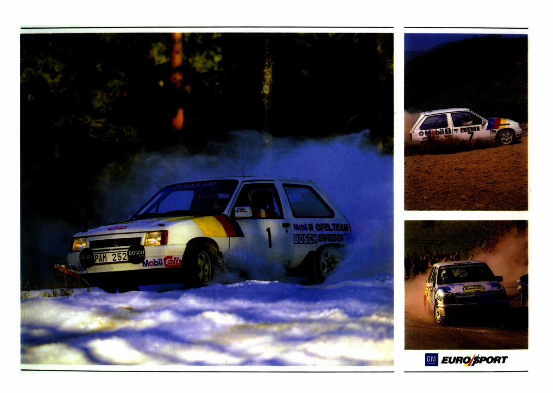
Front cover: Graham Turner
Produced by:
Printed by:J.T. McLaughlin Ltd., Euxton, Chorley.
Published by:Euro Sport Publications,Hadley House,Great Glen,Leicestershire. LE8 OGNEngland.
Martin Meadows Marketing.
FOREWORD
Ever since the basic Nova appeared on thecompetition scene back in 1985, clubmen havebeen recording success after success. In its firstyear of rallying, the potent GM Dealer SportNova GTE in the hands of Dave Metcalfe,showed a fantastic turn of speed, emphasising itscompetitiveness and serving notice of itspotential for honours.
That initial Nova GTE was put together byEngineer Brian Ashwood and his team. Theirbackground work prepared the foundation forthe new Nova/Corsa project, the Motor SportDevelopment engineers - David Gray, inparticular - developing and aquiring the manyand varied parts and components to produce the"Clubmans" Kit. The kit, together with thismanual now ensures that anyone can faithfullyreproduce the factory specification, relying onthe techniques and experience gathered frommany years of successful competition and,hopefully, gain the results that have now beenshown to be within the Nova/Corsa's capability.
This manual sets new standards in providingan exact and detailed guide to the preparation ofa vehicle for motorsport use. Andrew Duerden,together with Gordon Birtwistle, has tapped thatvast reservoir of specialist knowledge held by theMotor Sport Developments engineering staff toproduce a unique reference book. The mystiquebehind building a top-flight competition car hasnow been removed - now its down to the driver.
Good Luck.
Melvyn HodgsonChairman and Managing DirectorMotor Sport Developments

DISCLAIMER
Every effort has been made to ensure that thecontents of this publication were accurate andup-to-date at the time of going to press. Noliability can be accepted by the authors orpublishers for loss, damage or injury causedby errors in, or omission from, the informationgiven.
Motor sport can be hazardous and the in-clusion of any information does not necessarilymake it safe to use in any form of competitionor testing.
The modifications described in this publica-tion are, in some cases, of an extensive naturebut have all been specifically designed to givethe ultimate performance. These may adverselyaffect the normal life of standard parts andmay thus affect the New Vehicle Warranty.This does not mean that the performance carwill be unreliable - in fact, it may be assumedthat it will be at least as reliable as other cars ofcomparable performance.
Any inclusion of performance parts in theClubmans Kit or parts described in this bookletdoes not necessarily mean that the parts complywith the relevant homologation regulations orNational Type Approval requirements. It is thecompetitors responsibility to ensure that hisvehicle complies with regulations and is eligiblefor the specific homologation category for whichthe vehicle is entered.
I ntroduction
Model Availability
Homologation
Preparation
- Bodyshell
- Front suspension
- Power Steering
- Rear suspension
- The Braking system
- Engine
- Transmission
- Electrical
Group N guidelines
Appendix
- Clubmans Kit contents
- Homologation papers
CONTENTS


INTRODUCTION
This manual has been specifically produced inconjunction with the GM Euro Sport package ofparts assemblies and components produced byMotor Sport Developments and known as the"Clubmans Kits". Consequently, the text refersexclusively to the preparation of a Nova/Corsamodel to FIA International Group A level to thespecification within the Clubmans Kit. Otherparts and assemblies can be used in preparationof a group A Nova/Corsa, but they are notincluded in this manual and do not form part ofthe GM Euro Sport package.
The manual has been laid out with easy-to-read pages within well - defined sections. Thepreparation chapter has been sub-divided intovarious sections referring to vehicle sections -bodyshell, running gear, etc - this has then beensubdivided into the separate divisions relating tospecific components. At the end of each section,you will find a parts diagram together with a listof parts and assemblies referred to within thatsection. The actual pricing list is in a separatebooklet supplied with this manual.
Now you have received the manual, it is ofparamount importance that the registration cardat the front is completed and returned. This cardis the only method by which to ensure furtherupdates for the 12 month period followingregistration will be sent to you. As newequipment is developed or a component isevoluted, bulletins to update the manual willautomatically be sent to those who haveregistered on the cards provided.
This manual is designed to provide you withthe fullest information on the preparation of aNova/Corsa model for international rallying.We are always interested to know yourcomments in writing on any aspect that you feelcould be improved or modified. We will also behappy to receive any details of ommisions oritems that you would like to see in the manual.Only by feedback can we continue to improve onwhat is hoped will be a helpful and informativebook.

MODEL AVAILABILITY
When preparing a vehicle to the clubmansspecification contained in this manual, it isintended that the base vehicle used will be anexisting Nova GTE or Corsa GSi. These modelsare identical save for badging and very smalldifferences in trim. Additionally, some slightvariations on standard specification occurs,territory to territory. For instance, most NovaGTE models sold in the U.K. come equippedwith central locking and sunroofs. Corsa GSimodels sold in right hand drive form in theRepublic of Ireland do not have these two itemsfitted as standard. However, apart from theseminor differences, the main mechanicalcharacteristics remain the same.
The motive unit is a "Family One", nominal1600 cc, overhead camshaft, fuel injected typewhich is designated 1600 SE and, currently, isnot fitted to any other vehicle. The `Family One'group of engines (which includes the 1200 cc and1300 cc version with different bore/strokeconfigurations) also includes a carburettored1600 cc unit (known as 1600 SV type) which hasa different cylinder head and distributor to theSE motor, but in most other respects remains thesame.
The transmission is known as the F13 typeand the basic production unit is fitted, in fivespeed form, to all GM 1600 cc Family Oneengined Vauxhall and Opel cars.
The 1600cc injected Nova and CorsaGTE/GSi models were first introduced in thespring of 1988 and received no major revisionsto the standard specification until late 1990when a facelifted version was introduced. Thismodel incorporated revised bumpers, grille, frontwings and headlamps coupled with a newinterior styling package, and was referred to as aGSi in both Nova and Corsa livery.
Although this manual concentrates on thepreparation of vehicle using a Nova/CorsaGTE/GSi as a base, the section concerningbodyshell preparation does include details on theminor differences in bodyshells, if preparing a carfrom another hatchback bodyshell from therange of various cubic capacity Nova/Corsamodels. Vauxhall Nova GSi
HOMOLOGATION
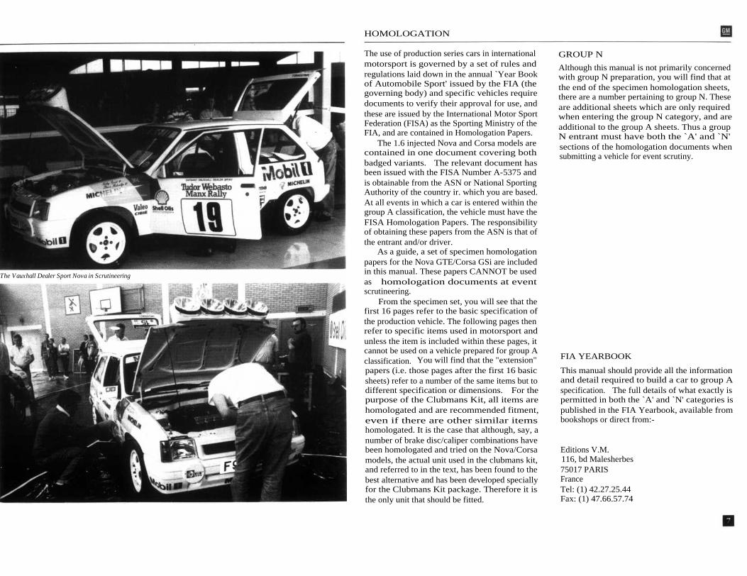
The Vauxhall Dealer Sport Nova in Scrutineering
The use of production series cars in internationalmotorsport is governed by a set of rules andregulations laid down in the annual `Year Bookof Automobile Sport' issued by the FIA (thegoverning body) and specific vehicles requiredocuments to verify their approval for use, andthese are issued by the International Motor SportFederation (FISA) as the Sporting Ministry of theFIA, and are contained in Homologation Papers.
The 1.6 injected Nova and Corsa models arecontained in one document covering bothbadged variants. The relevant document hasbeen issued with the FISA Number A-5375 andis obtainable from the ASN or National SportingAuthority of the country ir. which you are based.At all events in which a car is entered within thegroup A classification, the vehicle must have theFISA Homologation Papers. The responsibilityof obtaining these papers from the ASN is that ofthe entrant and/or driver.
As a guide, a set of specimen homologationpapers for the Nova GTE/Corsa GSi are includedin this manual. These papers CANNOT be usedas homologation documents at eventscrutineering.
From the specimen set, you will see that thefirst 16 pages refer to the basic specification ofthe production vehicle. The following pages thenrefer to specific items used in motorsport andunless the item is included within these pages, itcannot be used on a vehicle prepared for group Aclassification. You will find that the "extension"papers (i.e. those pages after the first 16 basicsheets) refer to a number of the same items but todifferent specification or dimensions. For thepurpose of the Clubmans Kit, all items arehomologated and are recommended fitment,even if there are other similar itemshomologated. It is the case that although, say, anumber of brake disc/caliper combinations havebeen homologated and tried on the Nova/Corsamodels, the actual unit used in the clubmans kit,and referred to in the text, has been found to thebest alternative and has been developed speciallyfor the Clubmans Kit package. Therefore it isthe only unit that should be fitted.
GROUP N
Although this manual is not primarily concernedwith group N preparation, you will find that atthe end of the specimen homologation sheets,there are a number pertaining to group N. Theseare additional sheets which are only requiredwhen entering the group N category, and areadditional to the group A sheets. Thus a groupN entrant must have both the `A' and `N'sections of the homologation documents whensubmitting a vehicle for event scrutiny.
FIA YEARBOOK
This manual should provide all the informationand detail required to build a car to group Aspecification. The full details of what exactly ispermitted in both the `A' and `N' categories ispublished in the FIA Yearbook, available frombookshops or direct from:-
Editions V.M.116, bd Malesherbes75017 PARISFranceTel: (1) 42.27.25.44Fax: (1) 47.66.57.74


BODYSHELL
The Bodyshell preparation and strengtheningprocedures outlined in this manual arefundamental to the success of the finishedproject. They will both extend the competitionlife of the shell and by increasing its torsionalstiffness contribute favourably towards thehandling characteristics of the finished vehicle.FIA Regulations, Appendix "J" for Touring cars,Group A permit a limited amount of bodyshellreinforcement, but it is important to adherestrictly to the definitions of the particular ArticleNo. 5.7:1 Lightening and Reinforcements. Allmodifications outlined within this chapter are incompliance with these guidelines.
General Motors Europe have extensivemotorsport experience with the Nova/Corsamodel and have developed a body strengtheningkit specifically for use in conjunction with the1600cc. model range. This kit includes all theadditional reinforcement plates required for thesuspension pick-up points, engine mountingpoints, roll cage pick-up points and a side jackingpoint, etc. When fitted in conjunction with therequisite additional welding as described, willgive an adequate degree of increased strengthand durability demanded by a motorsportenvironment.
A specially designed roll cage has beendeveloped and homologated for this model. Thiscage also incorporates the rear mounting pointsfor the safety harnesses.
Due to the nature of the modifications, theycan only be effectively carried out on a barebodyshell, so if your starting point is either a new1600 Nova GTE or Opel Corsa GSi, then allmechanical, trim and electrical components mustbe completely removed from the vehicle beforeembarking on any aspects of bodyshellpreparation. Whilst this section applies primarilyto bodyshells with Part Number 90297213LHD, or 90297215 RHD, bodyshells from othersources can be used, although they may differ inseveral basic respects. The main differencesbeing confined to the front suspension turretsand the inner and outer chassis rails. They havealready been additionally strengthened in the1600 models. From experience these bodyshells
do not present any problems under motorsportconditions, and are equally as good as the 1600shell when fully prepared with the bodystrengthening kit. Obviously some additionalplating and welding could be requiredparticularly in these areas on bodyshells from analternative source.
Before commencing any bodyshellpreparation operations, both front wings, doorsand tailgate must be removed from thebodyshell. All sound deadening material andgeneral sealants around all body seams can thenbe removed to provide more favourable weldingconditions. The application of heat to therequired area will enable any surplus material tobe scraped off more readily, finishing off theoperation with a wire brush. It's a fairlylaborious task but very important and ifthoroughly carried out will pay dividends at thewelding and later stages of preparation.
Any surplus brackets, unused supports suchas brakepipe/petrol pipe clip attachment pointscan be removed, and to enable a revised seatmounting system to be fitted, the standard seatadjustment/mounting brackets should also beremoved with care. This will enable a muchmore satisfactory installation of a wide range ofcompetition type seating for both driver and co-driver. Also carefully remove both the gearlevergaiter support bracket and the centre supportshelf from the centre tunnel section, in readinessfor the installation of the revised gearshift andlinkage at a later stage. Once the carpet centresupport has been removed, an elongated hole,approximately 80mm by 25mm must be formedin the centre section of the floor panel, along itscentreline, starting 80mm rearward of the tunnelto bulkhead bodyseam. This is to give access tothe engine bay for the revised gear linkage. Thearea of centre tunnel and exposed holei mmediately below the gearlever gaiter supportbracket can be closed off and strengthened usingthe shaped blanking plate supplied. This shouldbe welded into place.
The gear-linkage forward support bearinghousing bracket should be welded into positionat the forward end of the centre tunnel.

BODYSHELL
Access for this operation is from theunderbonnet and underside of the bodyshell.However, before welding this bracket into place,the bearing housing itself should be modified tofit the bracket correctly. This will entail cuttingaway a portion of the bearing housing flange justbelow two of the attachment holes. Three holesshould then be drilled through the housing andbracket, using the housing as a template. Threenuts should then be tack welded to the rear faceof the bracket. This will enable easy attachmentof the bearing housing to the bracket after it hasbeen welded into position.
This bracket is shaped to fit the exactposition required, and when measured should be65mm rearwards from the face of the steeringrack mounting plate. This should then exactlylocate the bracket in its correct position, whichwhen measured should be 65mm rearwards fromthe face of the steering rack mounting plate.NOTE: This is a delicate operation as thepositioning of this support bracket is crucial forsatisfactory gear linkage operation.
The aperture in the steering rack mountingbracket where it meets the lower chassis regionmust also be increased in size along the loweredge by removing 10mm from this flange. Seamweld the section after removing this metal.NOTE: This MUST be carried out at this stageto give adequate clearance for the revisedgearchange mechanism.Refer to the diagrams for guidance.
The bodyshell, now free from all unwanteditems, can be cleaned off in readiness for theseam welding and strengthening operation. Allexposed body seams throughout the bodyshellthat are actually spotwelded in the productionprocess require further "stitching", preferablywith a MIG-type welder. This entails making anadditional 25mm run of weld every 35mm alongEACH visible body seam throughout thebodyshell, and applies equally to the underside,underbonnet and bulkhead areas. However, thelower flanges of the front chassis rails where theyj oin the inner wheelarch require special attention.Using either a spotweld cutting tool or drill bit,carefully cut through ONE THICKNESS of the
seam in between each production spotweld andfill hole with weld, forming a "puddle weld". Inaddition to this operation, certain areas requirefurther reinforcement by welding on additional,specially profiled mild steel plates. These aresupplied in the kit, their profile following that ofthe original area and by double skinning give theadditional strength required. Final positioningwill be apparent when the plates are placedagainst the designated area, and should notrequire further modification prior to welding inplace. The inner pivot point for the bottomwishbone can be further strengthened by weldinga large metal washer onto the forward face. Thehole through the pivot should then be openedout to 12mm, to accommodate the largerdiameter bolt. The bodyshell also has in excessof 20 drain holes in the floorpan, these must beclosed off by welding the circular discs suppliedover the holes. The side lift jacking point cannow be fitted. Place the strengthening plateagainst the sill and mark the centre of the holerequired. This should be 22.5cm rear of thefront wing joint on the sill. Cut a 35mm. holethrough outer skin only. The inner 35mm. holeshould be formed with its centre 55mm. abovethe floor panel, so that when the tube isintroduced it is not parallel to the ground, butslopes upwards towards the inside of thebodyshell. The tube can now be insertedthrough the plate and sill, before finally weldinginto place.

Please note that both front wings MUST beremoved for this operation.
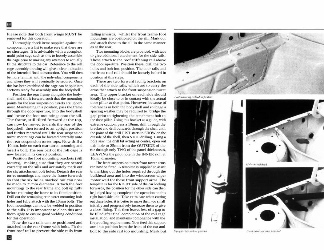
Thoroughly check items supplied against thecomponent parts list to make sure that there areno shortages. It is advisable with a complex,multi-point cage such as this to loosely assemblethe cage prior to making any attempts to actuallyfit the structure to the car. Reference to the rollcage assembly drawing will give a clear indicationof the intended final construction. You will thenbe more familiar with the individual componentsand where they will eventually be secured. Oncethis has been established the cage can be split intosections ready for assembly into the bodyshell.
Position the rear frame alongside the body-shell, and tilt it forward such that the mountingpoints for the rear suspension turrets are upper-most. Maintaining this position, pass the framethrough the door aperture, into the bodyshelland locate the foot mountings onto the sill.The frame, still tilted forward at the top,can now be moved towards the rear of thebodyshell, then turned to an upright positionand further rearward until the rear suspensionturret mountings can be located centrally ontothe rear suspension turret tops. Now drill a10mm. hole on each rear turret mounting and
i nsert a bolt. The rear part of the roll cage isnow located in its correct position.
Position the foot mounting brackets (SillMounts), making sure that they are seatedcorrectly on the sills and accurately mark outthe six attachment bolt holes. Detach the rearturret mountings and move the frame forwardsso that the six holes marked out can nowbe made to 25mm diameter. Attach the footmountings to the rear frame and bolt up fullybefore returning the frame to its fitted position.Drill out the remaining rear turret mounting boltholes and fully attach with the 10mm bolts. Thefoot mountings can now be welded in positionto the sills. It is important to clean this areathoroughly to ensure good welding conditionsfor this operation.
Now the two rails can be positioned andattached to the rear frame with bolts. Fit thefront roof rail to prevent the side rails from
falling inwards, whilst the front frame footmountings are positioned on the sill. Mark outand attach these to the sill in the same manneras at the rear.
Two mounting blocks are provided, with tabsto give additional attachment for the side rails.These attach to the roof stiffening rail abovethe door aperture. Position these, drill the twoholes and bolt into position. The door rails andthe front roof rail should be loosely bolted inposition at this stage.
There are two forward facing brackets oneach of the side rails, which are to carry thearms that attach to the front suspension turretarea. The upper bracket on each side shouldi deally be close to or in contact with the actualdoor pillar at that point. However, because oftolerances in both the bodyshell and rollcage aspacing washer may be required to `bridge thegap' prior to tightening the attachment bolt tothe door pillar. Using this bracket as a guide, withextreme caution, pass a 10mm. drill through thebracket and drill outwards through the shell untilthe point of the drill JUST starts to SHOW on theoutside of the shell, then STOP drilling. Using ahole saw, the drill bit acting as centre, open outthis hole to 25mm from the OUTSIDE of thecar through only TWO of the panel thicknesses,LEAVING the pilot hole in the INNER skin at10mm diameter.
The front suspension turret/front tower armscan now be fitted. A template is supplied to assistin marking out the holes required through thebulkhead area and into the windscreen wipermotor well for these front support arms. Thetemplate is for the RIGHT side of the car lookingforwards, the position for the other side can thenbe judged having completed the operation on thisright hand side unit. Take extra care when cuttingout these holes, it is better to make them too smallinitially and progressively increase them to givea close-fitting. This then leaves less of a gap tobe filled after final completion of the roll cageinstallation, and maintains compliance with thefireproofing requirements. Now feed this supportarm into position from the front of the car andbolt to the side rail top mounting. Mark out

BODYSHELL PROTECTION
the two holes alongside the suspension turretand drill out to 10mm. A third 10mm. hole hasto be drilled at the point where the diagonalsupport meets the front tower arm, but openedout to 25mm on the outer skin of the chassismember, to enable the fixing bolt to be insertedand tightened. Bodyshell and rollcage tolerancesagain may require spacing washers to be fitted to` bridge the gap' between the tower arm and thebody panel prior to tightening the attachmentbolt. Again, use the 10mm. hole as the pilothole for the hole saw. The diagonal supportarm can now be passed down through the wipermotor well area to the lower attachment point,the front tower arm can then be positioned andthe assembly fully secured. Repeat this procedurefor the other side of the car.
Four heavy gauge washers and fixing blocksare now left. These are for additional attachmentof the sides of the rear frame. Drill 10mm holesthrough the INNER SHELL ONLY, at the fourrear frame side mounting points. Pass the upperfixing block upwards inside the shell, position aheavy gauge washer between the shell and theframe, then retain by inserting the bolt. Repeatfor the lower fixing points. Check that all boltsand component parts are in place and that youare content with the general fit.
Now go round ALL attachment points andthoroughly tighten all bolts.
The strengthening and preparation is nowcomplete but it is suggested that the roll cagei s removed whilst the bodyshell is painted.
FRONT SUSPENSION BRACEThis is the last item under the general descriptionof body strengthening, and must be fitted to thecar by attaching to the front suspension topmounting bolts. This can be left until all the otheroperations have been carried out. Spacers may berequired to give adequate clearance between thebrace and the manifold on certain vehicles.
SUMP AND TANK SHIELDSAn undershielding kit has been developed for theGroup A car. This front shield protects the enginesump and transmission assembly, and attaches byfour bolts to the front mounting points for theforward facing, lower suspension arms. The rearof the shield is attached by two bolts, adjacent tothe inner pivot points for the lower wishbones.A threaded insert is already incorporated in thestrengthening plate supplied for this area andshould have been fitted during the bodyshellpreparations. The rear attachment points arenot pre-drilled in the sumpguard. These mustbe marked out to suit the individual vehicle withthe front of the sumpguard correctly attached.The holes must then be drilled out to size (12 to12.5mm) for positive location of the sumpguard,since this then becomes an integral part of thechassis.
NOTE: The hole positions can easily bemarked on to the shield by the following method.Remove the head from a 12mm bolt, screwthis remaining threaded portion into the rearattachment point leaving approximately 5mmof thread above the surface. Fit the shield tofront attachments and apply pressure to therear of the shield at each attachment point,the threaded section should then clearly markthe shield accurately where the holes should bedrilled.
The lighter gauge rear shield is profiled to fitaround the fuel tank area. The rear part of theshield attaches to the rear tank mounting points.Three holes must be drilled on either side of theshield, for bolting through the floor.
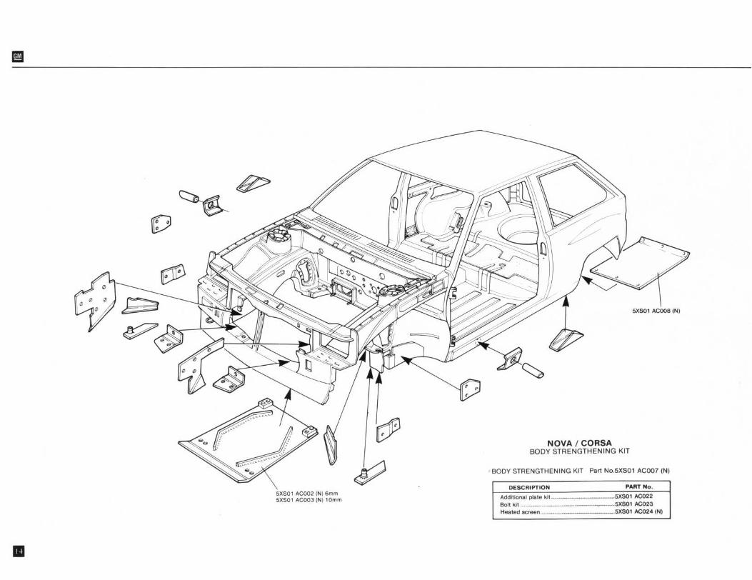

BODYSHELL PARTS LIST

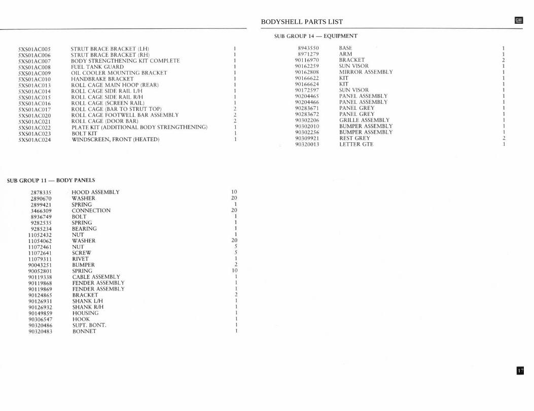
BODYSHELL PARTS LIST

FRONT SUSPENSION
The basic concept of the standard road car's
pick-up point using the larger 12mm boltsuspension layout has been retained but
supplied. This hole should have been enlarged toextensive modifications have been made to the
suit this bolt during the bodyshell preparation.way that the components have been constructed.
Prior to assembly, fit the front wheel bearingA revised front suspension assembly has been
to its housing in the knuckle and retain with thedesigned,
fabricated
and
homologated
two circlips. At this stage, press the drive flangespecifically for use in Group A motorsport, and
into the wheel bearing, and fit the wheel studs toMUST be used as a complete package. There is
this assembly. Fit the threaded insert into theno compatibility between individual components
mounting post clamp from the TOP face, secureand those found on the standard car.
by clamping with standard pinch bolt.
TheThis new assembly consists of a modified
knuckle assembly can now be attached to theknuckle assembly, fabricated lower control arm
lower control arm by a cap headed bolt andincorporating spherical joints, an adjustable,
washer inserted through the underside of thetubular lower suspension arm/castor control link,
outer spherical joint, into this threaded insert.complete with spherical bearing and reinforced
The lower suspension arm is attached to thefront attachment bracket. The heavy duty front
lower control arm at one end by a bolt, but thestrut body with adjustable spring platform
spherical joint at the opposite end locates with aposition, is fitted with a De Carbon monotube,
bracket attached to the front crossmember.gas filled shockabsorber insert. This attaches to
This has been profiled to fit the crossmemberthe knuckle assembly and incorporates a wheel
AFTER the strengthening plate for this point hascamber adjustment facility in the top securing
been attached, and has been designed to fit inbolt. The alloy top mounting uses a spherical
this original position using the three originalj oint housed eccentrically to allow further castor
mounting bolts. This bracket is also designed toand camber adjustment. The knuckle assembly
be used as the front attachment for thesupplied in the kit is derived from the normal
sumpguard.production component but has been further
The shockabsorber insert should be fitted tomachined within the wheel bearing housing to
the strut body, to be secured by a single nut, butaccept the larger diameter wheel bearing, and the
lightly lubricate the bearing surfaces and maketop mounting bolt hole enlarged to 14mm.
sure that the bump stop rubber is in place on theTo complement this package, a selection of
shockabsorber rod before assembly. The lower`superprogressive' road springs and suitably
spring guide ring, chosen road spring (springmatched dampers have been developed to cover
clamp required for this operation), top springtarmac and gravel applications.
plate, followed by the top mounting assemblyThese springs are constructed from tapered
can then be secured by a single nut. There iswire and offer a wheel travel capability coupled
provision for a grease nipple to be fitted to thewith increased spring rate, unattainable from
top part of the strut body, just above theconventionally constructed, constant wire
threaded section. Access to this nipple can bediameter springs.
made between the lower coils of the road springfor occasional lubrication with a proprietary
ASSEMBLY PROCEDURE
graphited grease.The completed shockabsorber and spring
Ensure that all components are thoroughly
assembly is attached to the knuckle using thecleaned and bushes lightly lubricated prior to
special bolt supplied. This 14mm. top bolt isassembly. Assemble under clean conditions at all
handed since it has an `eccentric' head to enabletimes. The spherical joints are located both in the
wheel camber adjustment.
The offset head oflower control arm and strut top mounting plate
this bolt fits between the two small angled platesby circlips. Attach lower control arm to chassis
on the strut body, the lock nut and special

hardened washer supplied should be fitted to theplain side.
These bolts must be tightened by a torquewrench immediately after the geometry has beenset to the required figures. This is a very criticalarea on the suspension, and as a precaution thetorque figure should be checked as a serviceoperation during vehicle use.
TIGHTENING TORQUES
Top Bolt,
14mm to 18kg/m. (130 Ib/ft.)Bottom Bolt,
12mm to 12kg/m. ( 90lb/ft.)
FRONT SUSPENSION DATA
As a direct result of National and Internationalrallying experience with this model, the GMEurosport development engineers in conjunctionwith their `team' drivers have optimised thesuspension settings for different types of eventand surfaces. It is suggested that these areadhered to particularly for the first competitiveouting, after which some drivers may prefer tomake their own subtle changes to these settingsto give slightly different handling characteristics.The package has been developed for optimumperformance without a front anti-roll bar.
When setting the castor and camber angles, itis vitally important that both sides of the carmeasure similarly. The tracking figures shouldalso be regularly checked, sudden discrepanciesin the measured data could indicate that somecomponent has been damaged. In Group Aspecification this is a very responsive vehicle andto maintain driver friendliness attention to thegeometry settings is a priority.
FRONT GEOMETRY DATA
DESCRIPTION
GRAVEL and OFF ROAD
2mm toe out
4 degrees +ve.
1 1 /2 degrees -ve.
TRACKING
CASTOR:
CAMBER:
NOTE: For predominantly radiused road surface,wheel camber to 1 1 /2 degrees -ve.
FRONT ROADSPRING DATA
Gravel and Off-Road Events.Superprogressive.Reference Number: 5XS03AC031European Tarmac Events.Superprogressive.Reference Number: 5XS03AC032Smooth Tarmac.. Spain or similar.Superprogressive.Reference Number: 5XS03AC033
NOTES: The springs have been designed to giveoptimum performance and correct vehicle rideheight, when the lower spring guide ring orplatform is set at 140mm. This is whenmeasured from the top edge of the springplatform to the knuckle attachment lugs.
GENERAL COMMENTS
When setting the suspension in the first instance,it is suggested that the top mountings hepositioned such as to give maximum positivecastor. That is with the top of the strut as far aspossible towards the rear of the suspension turretaperture. Further adjustment can then be carriedout at the knuckle and the spherically jointed endof the lower arm as required.
as
EURO TARMAC
LOW TARMAC:
2mm toe out
4 degrees +ve.
2 degrees -ve.
found in Ireland for example, reduce front


FRONT SUSPENSION PARTS LIST

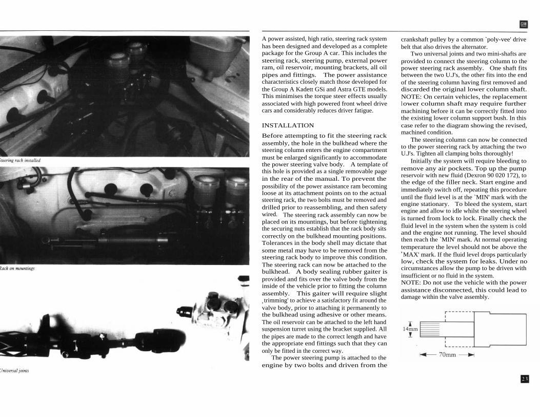
A power assisted, high ratio, steering rack systemhas been designed and developed as a completepackage for the Group A car. This includes thesteering rack, steering pump, external powerram, oil reservoir, mounting brackets, all oilpipes and fittings. The power assistancecharacteristics closely match those developed forthe Group A Kadett GSi and Astra GTE models.This minimises the torque steer effects usuallyassociated with high powered front wheel drivecars and considerably reduces driver fatigue.
INSTALLATION
Before attempting to fit the steering rackassembly, the hole in the bulkhead where thesteering column enters the engine compartmentmust be enlarged significantly to accommodatethe power steering valve body. A template ofthis hole is provided as a single removable pagein the rear of the manual. To prevent thepossibility of the power assistance ram becomingloose at its attachment points on to the actualsteering rack, the two bolts must be removed anddrilled prior to reassembling, and then safetywired. The steering rack assembly can now beplaced on its mountings, but before tighteningthe securing nuts establish that the rack body sitscorrectly on the bulkhead mounting positions.Tolerances in the body shell may dictate thatsome metal may have to be removed from thesteering rack body to improve this condition.The steering rack can now be attached to thebulkhead. A body sealing rubber gaiter isprovided and fits over the valve body from theinside of the vehicle prior to fitting the columnassembly. This gaiter will require slight, trimming' to achieve a satisfactory fit around thevalve body, prior to attaching it permanently tothe bulkhead using adhesive or other means.The oil reservoir can be attached to the left handsuspension turret using the bracket supplied. Allthe pipes are made to the correct length and havethe appropriate end fittings such that they canonly be fitted in the correct way.
The power steering pump is attached to theengine by two bolts and driven from the
crankshaft pulley by a common `poly-vee' drivebelt that also drives the alternator.
Two universal joints and two mini-shafts areprovided to connect the steering column to thepower steering rack assembly. One shaft fitsbetween the two U.J's, the other fits into the endof the steering column having first removed anddiscarded the original lower column shaft.NOTE: On certain vehicles, the replacementlower column shaft may require furthermachining before it can be correctly fitted intothe existing lower column support bush. In thiscase refer to the diagram showing the revised,machined condition.
The steering column can now be connectedto the power steering rack by attaching the twoU.J's. Tighten all clamping bolts thoroughly!
Initially the system will require bleeding toremove any air pockets. Top up the pumpreservoir with new fluid (Dexron 90 020 172), tothe edge of the filler neck. Start engine andimmediately switch off, repeating this procedureuntil the fluid level is at the `MIN' mark with theengine stationary. To bleed the system, startengine and allow to idle whilst the steering wheelis turned from lock to lock. Finally check thefluid level in the system when the system is coldand the engine not running. The level shouldthen reach the `MIN' mark. At normal operatingtemperature the level should not be above the'MAX' mark. If the fluid level drops particularlylow, check the system for leaks. Under nocircumstances allow the pump to be driven withinsufficient or no fluid in the system.NOTE: Do not use the vehicle with the powerassistance disconnected, this could lead todamage within the valve assembly.

REAR SUSPENSION WHFFT.S AND TYRFS
The standard rear axle beam is retained for theGroup A specification, and does not requireadditional strengthening. Special competitionbushes are supplied in the kit, and should befitted to the body mounting pivot point of therear axle. De-carbon gas filled shockabsorbershave been developed in conjunction withsuperprogressive `minibloc' rear springs forgravel and tarmac events. These must be used inconjunction with the corresponding front springsand shockabsorbers, as they are part of a fullyintegrated package. The 18mm. diameter anti-roll bar, standard fitment on the GTE/GSimodels, must be fitted for tarmac surfaceapplications. However, certain drivers may alsoprefer the loose surface handling characteristicsresulting from running with a rear anti-roll barfitted.
REAR ROADSPRING DATA
Gravel and Off-Road Events.Minibloc.Reference Number: 5XS04A0004All Tarmac Events.Minibloc.Reference Number: 5XS04A0005
NOTE: An additional spacer may be requiredunder the springs to achieve the correct rear rideheight and appearance when using the Europeantarmac front spring.
REAR SUSPENSION GEOMETRY
All conditions of use.CAMBER:
From 0 degrees 40 mins. negativeto 1 degree 35 mins negative.
( Maximum deviation Left to Right, 30 mins.)TRACKING: From 0.5mm. (5mins.) Toe Out
to 4.Omm. (40 mins.) Toe In.These parameters cannot be adjusted, and if theyfall outside of the above limits it would suggestthat the rear beam has become distorted.
Wheels have been specially produced for this carby O.Z. These are available in 15 inch diameter,with a 6 inch rim width. Experience has shownthat this gives the best possible wheel/tyreconfigurations from a performance point of viewfor both tarmac and loose surface use. They alsogive compatibility with a wide range of tyres andsizes permitted within this engine capacity classfrom most major tyre manufacturers.
PERFORMANCE DATA:Fifth gear @ 7600 RPM
Final Drive
Racing Tyres
Gravel TyresRatio 18/56-14 14/60-14
KPH/MPH KPH/MPH4.53:1 166.5/102.7 175.6/108.34.86:1 155.3/95.8 163.9/101.1
TYRE PRESSURES:
FRONT REARRacing tyres
2.0 Bar
1.6 BarGravel Tyres
1.8 Bar
1.6 Bar


THE BRAKING SYSTEM
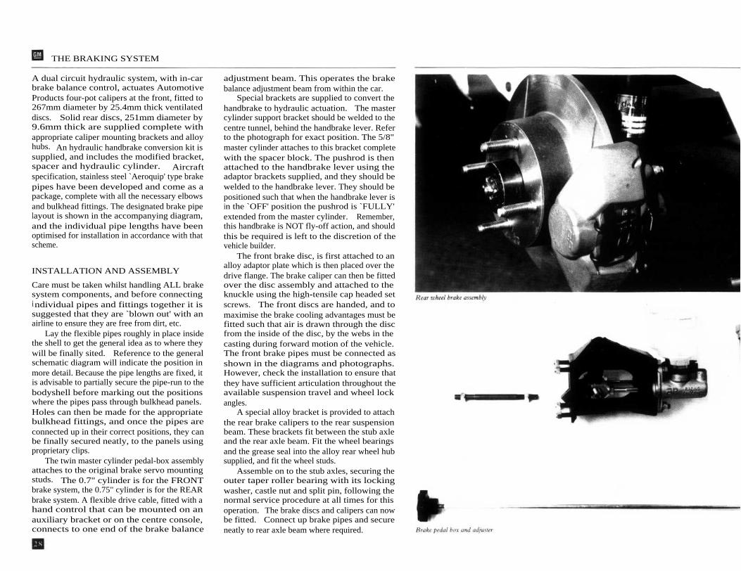
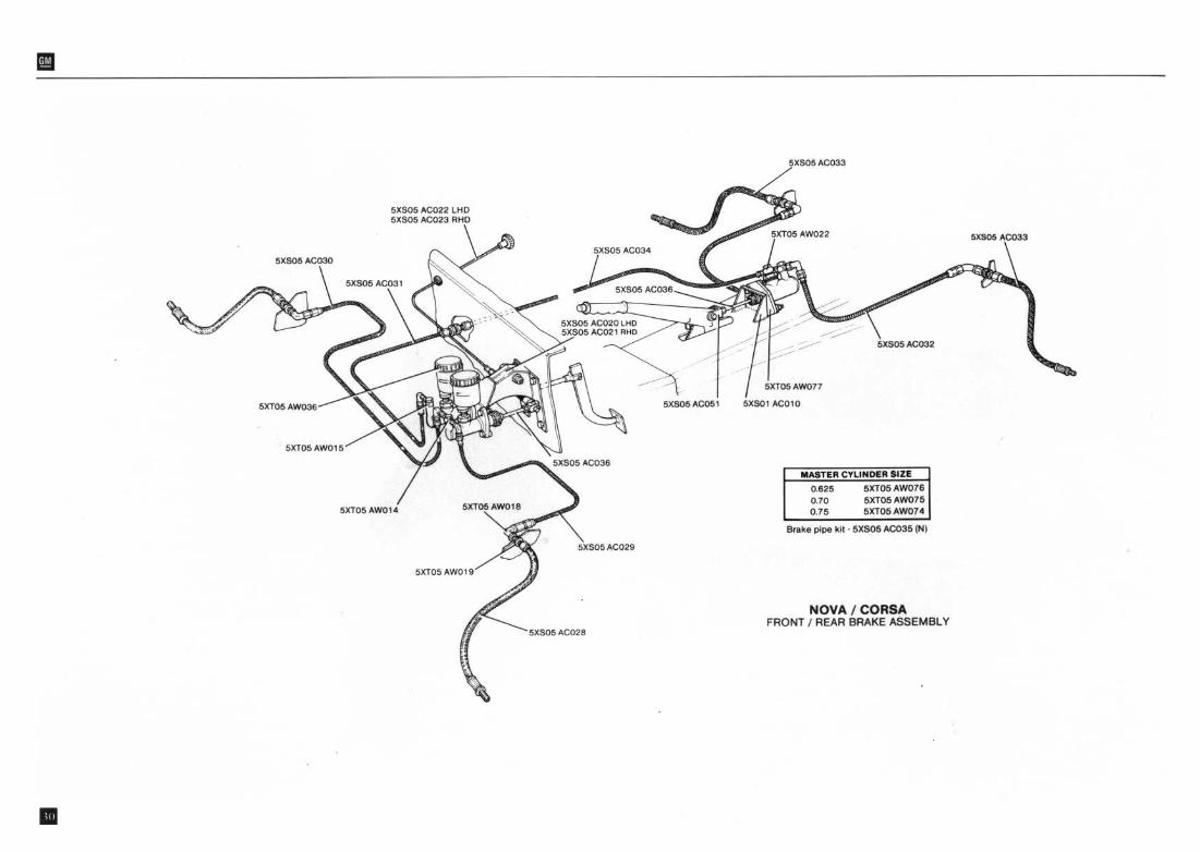
A dual circuit hydraulic system, with in-carbrake balance control, actuates AutomotiveProducts four-pot calipers at the front, fitted to267mm diameter by 25.4mm thick ventilateddiscs. Solid rear discs, 251mm diameter by9.6mm thick are supplied complete withappropriate caliper mounting brackets and alloyhubs. An hydraulic handbrake conversion kit issupplied, and includes the modified bracket,spacer and hydraulic cylinder. Aircraftspecification, stainless steel `Aeroquip' type brakepipes have been developed and come as apackage, complete with all the necessary elbowsand bulkhead fittings. The designated brake pipelayout is shown in the accompanying diagram,and the individual pipe lengths have beenoptimised for installation in accordance with thatscheme.
INSTALLATION AND ASSEMBLY
Care must be taken whilst handling ALL brakesystem components, and before connectingindividual pipes and fittings together it issuggested that they are `blown out' with anairline to ensure they are free from dirt, etc.
Lay the flexible pipes roughly in place insidethe shell to get the general idea as to where theywill be finally sited. Reference to the generalschematic diagram will indicate the position inmore detail. Because the pipe lengths are fixed, itis advisable to partially secure the pipe-run to thebodyshell before marking out the positionswhere the pipes pass through bulkhead panels.Holes can then be made for the appropriatebulkhead fittings, and once the pipes areconnected up in their correct positions, they canbe finally secured neatly, to the panels usingproprietary clips.
The twin master cylinder pedal-box assemblyattaches to the original brake servo mountingstuds. The 0.7" cylinder is for the FRONTbrake system, the 0.75" cylinder is for the REARbrake system. A flexible drive cable, fitted with ahand control that can be mounted on anauxiliary bracket or on the centre console,connects to one end of the brake balance
adjustment beam. This operates the brakebalance adjustment beam from within the car.
Special brackets are supplied to convert thehandbrake to hydraulic actuation. The mastercylinder support bracket should be welded to thecentre tunnel, behind the handbrake lever. Referto the photograph for exact position. The 5/8"master cylinder attaches to this bracket completewith the spacer block. The pushrod is thenattached to the handbrake lever using theadaptor brackets supplied, and they should bewelded to the handbrake lever. They should bepositioned such that when the handbrake lever isin the `OFF' position the pushrod is `FULLY'extended from the master cylinder. Remember,this handbrake is NOT fly-off action, and shouldthis be required is left to the discretion of thevehicle builder.
The front brake disc, is first attached to analloy adaptor plate which is then placed over thedrive flange. The brake caliper can then be fittedover the disc assembly and attached to theknuckle using the high-tensile cap headed setscrews. The front discs are handed, and tomaximise the brake cooling advantages must befitted such that air is drawn through the discfrom the inside of the disc, by the webs in thecasting during forward motion of the vehicle.The front brake pipes must be connected asshown in the diagrams and photographs.However, check the installation to ensure thatthey have sufficient articulation throughout theavailable suspension travel and wheel lockangles.
A special alloy bracket is provided to attachthe rear brake calipers to the rear suspensionbeam. These brackets fit between the stub axleand the rear axle beam. Fit the wheel bearingsand the grease seal into the alloy rear wheel hubsupplied, and fit the wheel studs.
Assemble on to the stub axles, securing theouter taper roller bearing with its lockingwasher, castle nut and split pin, following thenormal service procedure at all times for thisoperation. The brake discs and calipers can nowbe fitted. Connect up brake pipes and secureneatly to rear axle beam where required.

THE BRAKING SYSTEM
NOTE: The brake master cylinder combinationsupplied will give adequate brake balancecompensation for almost every surface condition.However, should the balance become a problemon events that include a large percentage ofextremely tortuous downhill sections on drytarmac, the rear braking can be reduced evenfurther by fitting a 7/8" master cylinder to theREAR brake system.
BRAKE MATERIAL INFORMATION
From our experience we would suggest fittingFerodo 2459 material for both front and rearbrake pads. This will give good all roundbraking performance and satisfactory brakebalance control for both tarmac and loosesurface conditions. There are of course,alternatives - Ferodo 3466 is a softer materialand DS 11 a much harder material.
Under some operating conditions a hardermaterial on the front pads may be aconsideration. However, since there is thepossibility that the DS11 material may notalways be running within its optimumtemperature range, the brake balance couldbecome inconsistent, and very REAR biased,even to the extent of continuous rear wheellocking. Should these circumstances prevail, thechoice of DS 11 has not been the correct decision.Revert to the recommended Ferodo 2459.

BRAKES PARTS LIST
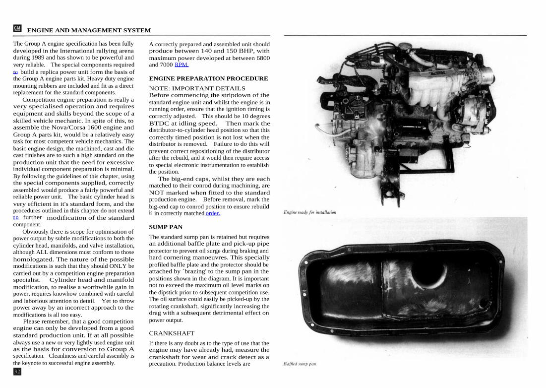
ENGINE AND MANAGEMENT SYSTEM
The Group A engine specification has been fully
A correctly prepared and assembled unit shoulddeveloped in the International rallying arena
produce between 140 and 150 BHP, withduring 1989 and has shown to be powerful and
maximum power developed at between 6800very reliable.
The special components required
and 7000 RPM.to build a replica power unit form the basis ofthe Group A engine parts kit. Heavy duty engine
ENGINE PREPARATION PROCEDUREmounting rubbers are included and fit as a direct
NOTE: IMPORTANT DETAILSreplacement for the standard components.
Before commencing the stripdown of theCompetition engine preparation is really a
standard engine unit and whilst the engine is invery specialised operation and requires
running order, ensure that the ignition timing isequipment and skills beyond the scope of a
correctly adjusted. This should be 10 degreesskilled vehicle mechanic. In spite of this, to
BTDC at idling speed.
Then mark theassemble the Nova/Corsa 1600 engine and
distributor-to-cylinder head position so that thisGroup A parts kit, would be a relatively easy
correctly timed position is not lost when thetask for most competent vehicle mechanics. The
distributor is removed.
Failure to do this willbasic engine design, the machined, cast and die
prevent correct repositioning of the distributorcast finishes are to such a high standard on the
after the rebuild, and it would then require accessproduction unit that the need for excessive
to special electronic instrumentation to establishindividual component preparation is minimal.
the position.By following the guidelines of this chapter, using
The big-end caps, whilst they are eachthe special components supplied, correctly
matched to their conrod during machining, areassembled would produce a fairly powerful and
NOT marked when fitted to the standardreliable power unit. The basic cylinder head is
production engine. Before removal, mark thevery efficient in it's standard form, and the
big-end cap to conrod position to ensure rebuildprocedures outlined in this chapter do not extend
is in correctly matched order.to further modification of the standardcomponent.
SUMP PANObviously there is scope for optimisation of
power output by subtle modifications to both the
The standard sump pan is retained but requires
cylinder head, manifolds, and valve installation,
an additional baffle plate and pick-up pipe
although ALL dimensions must conform to those
protector to prevent oil surge during braking and
homologated. The nature of the possible
hard cornering manoeuvres. This specially
modifications is such that they should ONLY be
profiled baffle plate and the protector should be
carried out by a competition engine preparation
attached by `brazing' to the sump pan in the
specialist.
Cylinder head and manifold
positions shown in the diagram. It is important
modification, to realise a worthwhile gain in
not to exceed the maximum oil level marks on
power, requires knowhow combined with careful
the dipstick prior to subsequent competition use.
and laborious attention to detail. Yet to throw
The oil surface could easily be picked-up by the
power away by an incorrect approach to the
rotating crankshaft, significantly increasing the
modifications is all too easy.
drag with a subsequent detrimental effect on
Please remember, that a good competition
power output.engine can only be developed from a goodstandard production unit. If at all possible
CRANKSHAFT
always use a new or very lightly used engine unit
If there is any doubt as to the type of use that theas the basis for conversion to Group A
engine may have already had, measure thespecification. Cleanliness and careful assembly is
crankshaft for wear and crack detect as athe keynote to successful engine assembly.
precaution. Production balance levels are

ENGINE
already very good and no further balancing isrequired. If the crankshaft is not as new, lightlypolish the journals with a suitable grade ofcrankshaft finishing tape. Thoroughly clean thecomponent with petrol or other suitable solvent.Blow out the oil passages with compressed airprior to reassemble. The main bearing shells andbolts are as production.
PISTONS AND CONRODS
To give the correct increase in the compressionratio and increased durability, Cosworth, fullskirt, forged pistons are supplied. These have alighter gudgeon pin which is a pressed fit into thesmall end bearing, as in the normal productioncondition. The Cosworth pistons are sized to becompatible ONLY with the standard productionbore dimensions. These are in fact graded, butthe increased operating clearances with theCosworth piston easily accommodates any slightvariance in bore size.
The Cosworth piston is a direct replacementfor the standard unit, which can be discarded.Circlip grooves are evident around the gudgeonpin housing on the Cosworth piston, these mustbe completely disregarded as circlips are notrequired for this application. As a precaution theconrods should be crack detected after thestandard pistons have been removed and prior toassembly with the replacement pistons.However, both the removal and fitting of thepistons to the conrods is a specialised operationand must be carried out by appropriatelyqualified and equipped personnel. Heavy dutyconrod bearing cap retaining bolts are suppliedwhich also give more positive bearing capalignment.
The pistons have a designed `deck height' togive a compression ratio of approximately11.4:1, and when installed should protrudeabove the block face at top dead centre by0.4mm. plus or minus 0.10mm. (0.016ins, plusor minus 0.004ins.) This dimension should bechecked in case of block discrepancies.
ENGINE BLOCK
78.995mm. to 79.025mm3.11ins. to 3.1112ins.
CYLINDER HEAD ASSEMBLY
The bore size must be standard to remain withinthe 1600cc maximum capacity limits and shouldtherefore conform to the following dimensions.
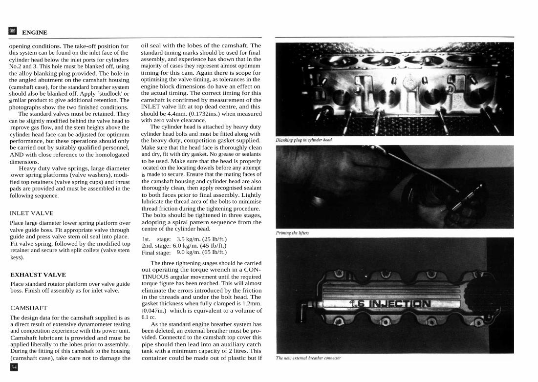
An oversize, competition piston has not beendeveloped. Prior to assembly, deglaze bores to amicro finish and 45 degree hatch pattern. Thetake-off hole for the standard engine breathertower assembly, situated on the inlet side ofthe block, must be blanked off with the platesupplied. See photograph for the detail. Assemblei n accordance with normal build procedures.
Carefully dismantle the cylinder head, placingeach component in numbered removal order sothat the parts required can be reassembled intheir original positions.
Prior to further cylinder head preparations,a modification to give increased oil supply tothe hydraulic lifters, thus ensuring adequateoil pressure under high oil temperature andsustained high engine speed operating conditionsMUST be carried out. The oil pressure feed holei n the cylinder head casting, situated at theexhaust side of the cylinder head face shouldbe increased in diameter. This operation requiresextra care, and entails drilling out the existing, angled' 2mm. hole to 3mm. The hole must beenlarged throughout its depth (approximately40mm.), until it joins with the larger diameterpart of the `gallery' section, taking extra careto follow the path of the existing `angled'hole. Make sure that the oil passages do notcontain any residual swarf after completion ofthe modification. Follow standard proceduresfor cylinder head refurbishing.
The production Nova/Corsa 1600 enginefeatures exhaust gas recirculation. This is partof the emission control system, where regulatedquantities of the exhaust gasses are recycledthrough the inlet tracts under certain throttle
ENGINE
opening conditions. The take-off position forthis system can be found on the inlet face of thecylinder head below the inlet ports for cylindersNo.2 and 3. This hole must be blanked off, usingthe alloy blanking plug provided. The hole inthe angled abutment on the camshaft housing(camshaft case), for the standard breather systemshould also be blanked off. Apply `studlock' orsimilar product to give additional retention. Thephotographs show the two finished conditions.
The standard valves must be retained. Theycan be slightly modified behind the valve head toi mprove gas flow, and the stem heights above thecylinder head face can be adjusted for optimumperformance, but these operations should onlybe carried out by suitably qualified personnel,AND with close reference to the homologateddimensions.
Heavy duty valve springs, large diameterl ower spring platforms (valve washers), modi-fied top retainers (valve spring cups) and thrustpads are provided and must be assembled in thefollowing sequence.
INLET VALVE
Place large diameter lower spring platform overvalve guide boss. Fit appropriate valve throughguide and press valve stem oil seal into place.Fit valve spring, followed by the modified topretainer and secure with split collets (valve stemkeys).
EXHAUST VALVE
Place standard rotator platform over valve guideboss. Finish off assembly as for inlet valve.
CAMSHAFT
The design data for the camshaft supplied is asa direct result of extensive dynamometer testingand competition experience with this power unit.Camshaft lubricant is provided and must beapplied liberally to the lobes prior to assembly.During the fitting of this camshaft to the housing(camshaft case), take care not to damage the
oil seal with the lobes of the camshaft. Thestandard timing marks should be used for finalassembly, and experience has shown that in themajority of cases they represent almost optimumtiming for this cam. Again there is scope foroptimising the valve timing, as tolerances in theengine block dimensions do have an effect onthe actual timing. The correct timing for thiscamshaft is confirmed by measurement of theINLET valve lift at top dead centre, and thisshould be 4.4mm. (0.1732ins.) when measuredwith zero valve clearance.
The cylinder head is attached by heavy dutycylinder head bolts and must be fitted along withthe heavy duty, competition gasket supplied.Make sure that the head face is thoroughly cleanand dry, fit with dry gasket. No grease or sealantsto be used. Make sure that the head is properlyl ocated on the locating dowels before any attemptis made to secure. Ensure that the mating faces ofthe camshaft housing and cylinder head are alsothoroughly clean, then apply recognised sealantto both faces prior to final assembly. Lightlylubricate the thread area of the bolts to minimisethread friction during the tightening procedure.The bolts should be tightened in three stages,adopting a spiral pattern sequence from thecentre of the cylinder head.
1st.
stage: 3.5 kg/m. (25 Ib/ft.)2nd. stage: 6.0 kg/m. (45 Ib/ft.)Final stage: 9.0 kg/m. (65 Ib/ft.)
The three tightening stages should be carriedout operating the torque wrench in a CON-TINUOUS angular movement until the requiredtorque figure has been reached. This will almosteliminate the errors introduced by the frictionin the threads and under the bolt head. Thegasket thickness when fully clamped is 1.2mm.( 0.047in.) which is equivalent to a volume of6.1 cc.
As the standard engine breather system hasbeen deleted, an external breather must be pro-vided. Connected to the camshaft top cover thispipe should then lead into an auxiliary catchtank with a minimum capacity of 2 litres. Thiscontainer could be made out of plastic but if
ENGINE
made from a non-translucent material musti nclude a transparent window for compliancewith Appendix `J' Group A. See photographshowing additional elbow in place.
LUBRICATION SYSTEMThe standard oil pump is retained and is capableof giving adequate flow and pressure for thisengine specification. However, in view of themodifications to the oil feed in the cylinderhead casting, the oil pressure relief valve mustbe adjusted to compensate. This entails the fittingof a 3mm. shim behind the pressure relief valvespring to increase its pre-load. The oil coolerconnects to the engine by a sandwich plate thatattaches to the block, between the oil filter unit.The high pressure pipes are made to the correctlength for connection to the oil cooler radiatorwhen fitted to the left hand side of the frontpanel, viewed from the front of the car. Aspecial attachment bracket is supplied. Beforeassembly, fill oil radiator and pipes with chosenengine oil.
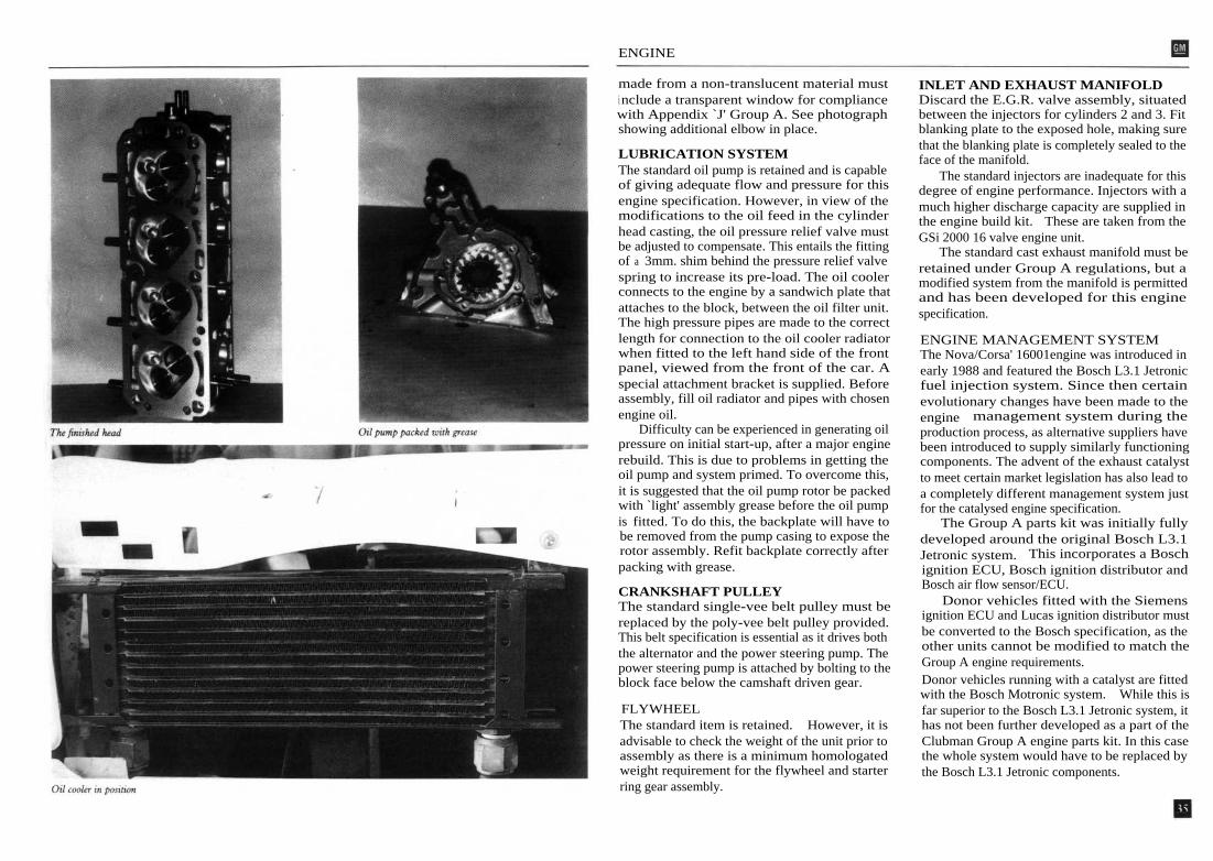
Difficulty can be experienced in generating oilpressure on initial start-up, after a major enginerebuild. This is due to problems in getting theoil pump and system primed. To overcome this,it is suggested that the oil pump rotor be packedwith `light' assembly grease before the oil pumpis fitted. To do this, the backplate will have tobe removed from the pump casing to expose therotor assembly. Refit backplate correctly afterpacking with grease.
CRANKSHAFT PULLEYThe standard single-vee belt pulley must bereplaced by the poly-vee belt pulley provided.This belt specification is essential as it drives boththe alternator and the power steering pump. Thepower steering pump is attached by bolting to theblock face below the camshaft driven gear.
FLYWHEELThe standard item is retained. However, it isadvisable to check the weight of the unit prior toassembly as there is a minimum homologatedweight requirement for the flywheel and starterring gear assembly.
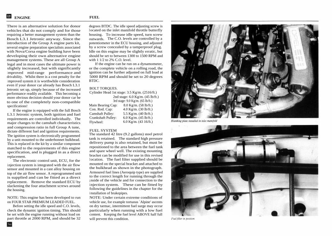
INLET AND EXHAUST MANIFOLDDiscard the E.G.R. valve assembly, situatedbetween the injectors for cylinders 2 and 3. Fitblanking plate to the exposed hole, making surethat the blanking plate is completely sealed to theface of the manifold.
The standard injectors are inadequate for thisdegree of engine performance. Injectors with amuch higher discharge capacity are supplied inthe engine build kit. These are taken from theGSi 2000 16 valve engine unit.
The standard cast exhaust manifold must beretained under Group A regulations, but amodified system from the manifold is permittedand has been developed for this enginespecification.
ENGINE MANAGEMENT SYSTEMThe Nova/Corsa' 16001engine was introduced inearly 1988 and featured the Bosch L3.1 Jetronicfuel injection system. Since then certainevolutionary changes have been made to theengine management system during theproduction process, as alternative suppliers havebeen introduced to supply similarly functioningcomponents. The advent of the exhaust catalystto meet certain market legislation has also lead toa completely different management system justfor the catalysed engine specification.
The Group A parts kit was initially fullydeveloped around the original Bosch L3.1Jetronic system. This incorporates a Boschignition ECU, Bosch ignition distributor andBosch air flow sensor/ECU.
Donor vehicles fitted with the Siemensignition ECU and Lucas ignition distributor mustbe converted to the Bosch specification, as theother units cannot be modified to match theGroup A engine requirements.Donor vehicles running with a catalyst are fittedwith the Bosch Motronic system. While this isfar superior to the Bosch L3.1 Jetronic system, ithas not been further developed as a part of theClubman Group A engine parts kit. In this casethe whole system would have to be replaced bythe Bosch L3.1 Jetronic components.
ENGINE FUEL
There is an alternative solution for donorvehicles that do not comply and for thoserequiring a better management system than theBosch L3.1 Jetronic anyway. Since theintroduction of the Group A engine parts kit,several engine preparation specialists associatedwith Nova/Corsa engine building have beendeveloping their own alternative enginemanagement systems. These are all Group Alegal and in most cases the ultimate power isslightly increased, but with significantlyi mproved mid-range performance anddrivability. Whilst there is a cost penalty for thei mproved system it is worthwhile considerationeven if your donor car already has Bosch L3.1Jetronic set up, simply because of the increasedperformance readily available. This becoming amore obvious decision should your donor car beto one of the completely non-compatiblespecifications!
If the engine is equipped with the full BoschL3.1 Jetronic system, both ignition and fuelrequirements are controlled individually. Themajor changes to the camshaft characteristicsand compression ratio in full Group A tune,dictate different fuel and ignition requirements.The ignition system is electronically programmedby a unit mounted to the underbonnet bulkhead.This is replaced in the kit by a similar componentmatched to the requirements of this enginespecification, and is plugged in as a directreplacement.
The electronic control unit, ECU, for theinjection system is integrated with the air flowsensor and mounted in a cast alloy housing ontop of the air flow sensor. A reprogrammed unitis supplied and can be fitted as a directreplacement. Remove the standard ECU byslackening the four attachment screws aroundthe housing.
NOTE: This engine has been developed to runon FOUR STAR PREMIUM LEADED FUEL.
Before setting the idle speed and C.O. levels,check the dynamic ignition timing. This shouldbe set with the engine running without load onpart throttle at 2000 RPM, and should be 32
degrees BTDC. The idle speed adjusting screw islocated on the inlet manifold throttle butterflyhousing. To increase idle speed, turn screwoutwards. The C.O. levels are controlled by apotentiometer in the ECU housing, and adjustedby a screw concealed by a tamperproof plug.Idle on this engine may be slightly erratic, butshould be set to between 1300 to 1500 RPM andwith 1 1/2 to 2% C.O. level.
If the engine can be run on a dynamometer,or the complete vehicle on a rolling road, theignition can be further adjusted on full load at5000 RPM and should be set to 20 degreesBTDC.
BOLT TORQUES.Cylinder Head 1st stage: 3.5 Kg/m. (2516/ft.)
2nd stage: 6.0 Kg/m. (45 lb/ft.)3rd stage: 9.0 Kg/m. (65 lb/ft.)
Main Bearing Cap:
8.0 Kg/m. (58 lb/ft.)Con. Rod. Cap:
4.0 Kg/m. (30 lb/ft.)Camshaft Pulley:
5.5 Kg/m. (40 lb/ft.)Crankshaft Pulley:
6.0 Kg/m. (45 lb/ft.)Flywheel:
6.0 Kg/m. (43 16/ft.)
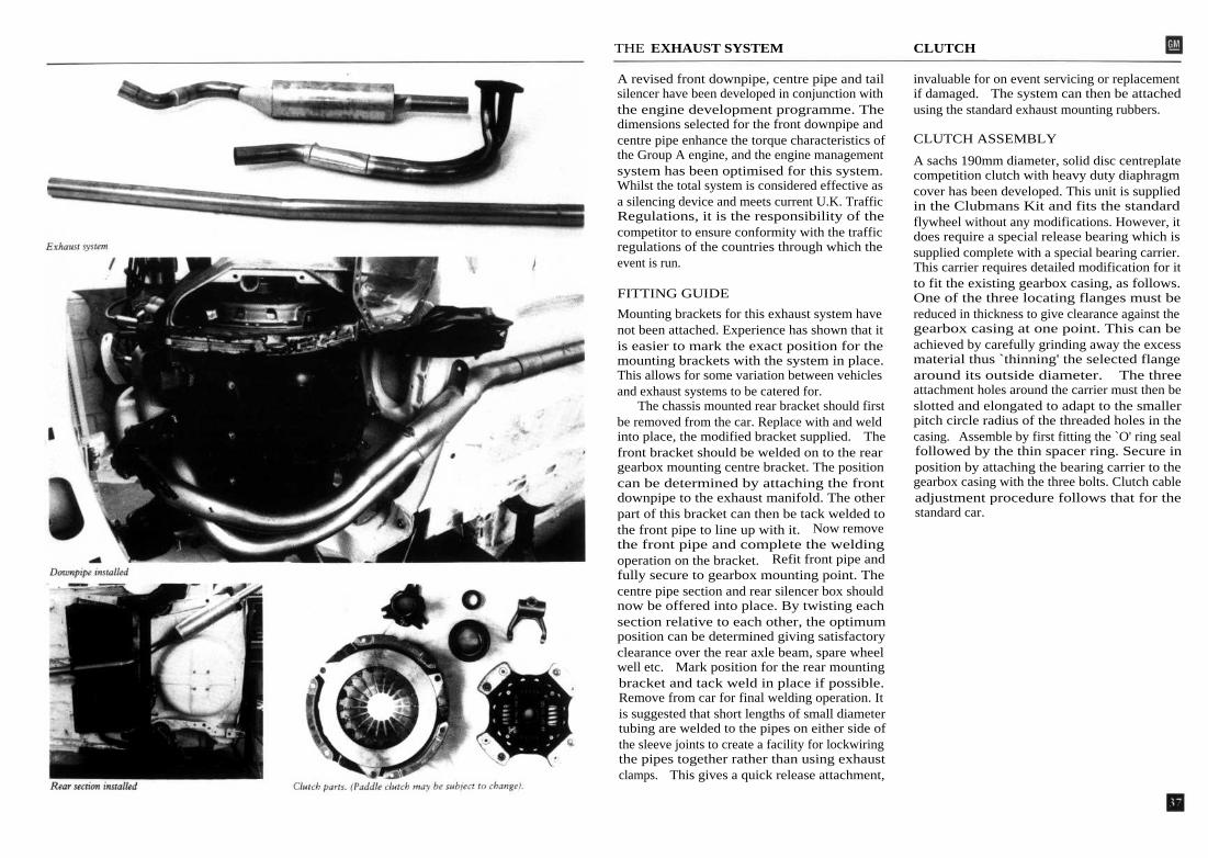
FUEL SYSTEMThe standard 42 litre (9.2 gallons) steel petroltank is retained. The standard high pressuredelivery pump is also retained, but must berepositioned to the area between the fuel tankand spare wheel well. The existing mountingbracket can be modified for use in this revisedlocation. The fuel filter supplied should bemounted on the special bracket and attached tothe bulkhead as shown in the photograph.Armoured fuel lines (Aeroquip type) are suppliedto the correct length for running through theinside of the vehicle and for connection to theinjection system. These can be fitted byfollowing the guidelines in the chapter for theinstallation of brakepipes.NOTE: Under certain extreme conditions ofvehicle use, for example tortuous `Alpine' ascentson dry tarmac, intermittent fuel surge may occurparticularly when running with a low fuelcontent. Keeping the fuel level ABOVE half fullwill prevent this condition.
THE EXHAUST SYSTEM CLUTCH
A revised front downpipe, centre pipe and tailsilencer have been developed in conjunction withthe engine development programme. Thedimensions selected for the front downpipe andcentre pipe enhance the torque characteristics ofthe Group A engine, and the engine managementsystem has been optimised for this system.Whilst the total system is considered effective asa silencing device and meets current U.K. TrafficRegulations, it is the responsibility of thecompetitor to ensure conformity with the trafficregulations of the countries through which theevent is run.
FITTING GUIDE
Mounting brackets for this exhaust system havenot been attached. Experience has shown that itis easier to mark the exact position for themounting brackets with the system in place.This allows for some variation between vehiclesand exhaust systems to be catered for.
The chassis mounted rear bracket should firstbe removed from the car. Replace with and weldinto place, the modified bracket supplied. Thefront bracket should be welded on to the reargearbox mounting centre bracket. The positioncan be determined by attaching the frontdownpipe to the exhaust manifold. The otherpart of this bracket can then be tack welded tothe front pipe to line up with it. Now removethe front pipe and complete the weldingoperation on the bracket. Refit front pipe andfully secure to gearbox mounting point. Thecentre pipe section and rear silencer box shouldnow be offered into place. By twisting eachsection relative to each other, the optimumposition can be determined giving satisfactoryclearance over the rear axle beam, spare wheelwell etc. Mark position for the rear mountingbracket and tack weld in place if possible.Remove from car for final welding operation. Itis suggested that short lengths of small diametertubing are welded to the pipes on either side ofthe sleeve joints to create a facility for lockwiringthe pipes together rather than using exhaustclamps. This gives a quick release attachment,
invaluable for on event servicing or replacementif damaged. The system can then be attachedusing the standard exhaust mounting rubbers.
CLUTCH ASSEMBLY
A sachs 190mm diameter, solid disc centreplatecompetition clutch with heavy duty diaphragmcover has been developed. This unit is suppliedin the Clubmans Kit and fits the standardflywheel without any modifications. However, itdoes require a special release bearing which issupplied complete with a special bearing carrier.This carrier requires detailed modification for itto fit the existing gearbox casing, as follows.One of the three locating flanges must bereduced in thickness to give clearance against thegearbox casing at one point. This can beachieved by carefully grinding away the excessmaterial thus `thinning' the selected flangearound its outside diameter. The threeattachment holes around the carrier must then beslotted and elongated to adapt to the smallerpitch circle radius of the threaded holes in thecasing. Assemble by first fitting the `O' ring sealfollowed by the thin spacer ring. Secure inposition by attaching the bearing carrier to thegearbox casing with the three bolts. Clutch cableadjustment procedure follows that for thestandard car.

ENGINE PARTS LIST


GEARBOX AND DIFFERENTIAL ASSEMBLY
A close ratio 'dog type' gearbox kit has beenspecially developed for this model. This gearboxutilises the casing and intermediate housing or'sandwich plate' from the standard car's F13speed gearbox but the component parts of theclose ratio kit must be assembled along with arevised end cover and gearshift cover assembly.As this is a heavy-duty gearbox unit, many ofthe component parts are larger that the corre-sponding standard item. To accommodate thesesome detailed internal modifications must becarried out on the casing BEFORE commencingassembly operations.
CASING MODIFICATIONS
The following operations are required within thearea normally containing the DIFFERENTIALUNIT.
Remove the speedometer drive gear assemblyand blank off the hole with the blanking plugsupplied. The speedometer drive gear supportl ug can now be removed by grinding awaythe excess material. Also 'chamfer' the regionadjacent to this blanking plug and removeexcess material by creating a 'flattened' profileto the area immediately above the centrelineof the differential bearing housings. This willgive the additional clearance required for easyi nstallation of the differential assembly. Cleanoff all internal rough edges due to variances incastings to give clearance for the crown wheel.
The following operations are required withinthe area normally containing the GEARBOXASSEMBLIES.
The reverse gear shaft support housing isalready machined to 'convex' profile, this mustbe further modified by grinding to a 'rounded'profile. To ensure COMPLETE engagement ofthe dog teeth in 4th gear, the 1st/2nd and3rd/4th gear selector shaft support housing mustbe spot-faced, removing 1.5mm from the entireface of the casting at this point. The casting mustalso be relieved by further radiuses in the cornerof this area, to give additional clearance betweenthe casing and the selector fork enabling it to buttagainst this machined face. The amount to be
removed can easily be determined by insertingthe selector fork and shaft into position in thecasing as a guide. Since the 4th gear wheel is largerthan the standard item, a considerable amountof material must be removed from the casing atthe point where the gear cluster encroaches intothe differential housing. Approximately 2mmclearance is called for when assembled, and thisclearance can be viewed through the aperture indifferential case when the gearbox cluster is fittedi nto the casing.
Modifications to INTERMEDIATE HOUS-I NG or SANDWICH PLATE.
The mainshaft bearing housing will foul onthe 1st gear wheel unless the casting marksare removed by rounding off the affected areabefore assembly. The amount of material to beremoved can easily be confirmed by offering upthe mainshaft complete with the gear. All theabove mentioned points are highlighted in theillustrations for this chapter.
GEARBOX ASSEMBLY PROCEDURE
It is very important that all the parts requiredare thoroughly cleaned prior to commencingreassembly of the gearbox and a clean, swarf-freearea is reserved for the build.
Carefully remove all gears from the mainshaft,since they have only been fitted loosely to the shaftfor packaging purposes. It may be prudent to notethe sequence of this assembly and confirm withthe diagrams provided.
The final drivegear pinion is integral withthe mainshaft, but prior to further assemblycarefully fit the spacing washer behind thegear, making sure that the small locating balli s correctly located in the small hole provided inthe shaft and spacer, thus preventing the spacerfrom revolving.
Now lightly lubricate the roller bearings andslide over the mainshaft, along with the gearwheels and selector hubs in the order andposition shown by the exploded diagrams andphotographs.
NOTE: If the donor gearbox has already cov-ered a significant distance, renew the mainshaft
GEARBOX AND DIFFERENTIAL ASSEMBLY
and 1st motion shaft bearings as a precaution.Now at this stage the mainshaft bearing can
be fitted into its housing in the sandwich plateand secured with the correct circlip. For easeof assembly, press the other bearing on to the1st motion shaft and loosely position its largeretaining circlip behind the bearing in readinessfor final assembly. This circlip CANNOT befitted AFTER this shaft and bearing have beenpressed into the sandwich plate. The sandwichplate must now be supported in a vice withthe gearbox side facing towards you. Takehold of the two assemblies, (mainshaft and1st motion shaft) and whilst holding the two`in mesh', simultaneously introduce the shafts totheir respective positions `through' the sandwichplate. That is the mainshaft into its bearing, the1st motion shaft and bearing into its housing,securing the 1st motion shaft with the large circlipbehind the bearing.
Now reposition this assembly in the vice,turning it through 180 degrees such that thegear clusters are behind the sandwich plate andfacing away from you.
Place the 1st/2nd gear selector fork aroundits hub and press the selector shaft through thisfork and into the sandwich plate. Ensure that thedetent grooves are uppermost and then carefullysecure the fork to the shaft with two roll-pins.The 5th gear selector rod assembly can nowbe inserted through the sandwich plate andthe 3rd/4th gear selector fork placed aroundits hub.
Engage 2ND GEAR and push the mainshaftaway from you to the full extent of the availablefree movement. This will give better access toinstall and secure the interlock pin assemblyto the sandwich plate with two cap headedbolts. Once this is fitted, the mainshaft canbe returned to its correct position up againstthe bearing, and the 1st/2nd gear selector rodreturned to the NEUTRAL position. The 3rd/4thgear selector rod can now be inserted through theaxis of the 5th gear selector assembly, into the3rd/4th gear selector fork and secured with careby roll-pins. The 5th gear pawl assembly shouldnow be attached to the sandwich plate using two
cap-headed bolts, making sure that the slot inthe 3rd/4th gear selector rod located the end ofthe pawl.
The 5th gear complete with its hub andselector fork can now be fitted to the end ofthe mainshaft. The selector fork locates on theend of the 5th gear selector rod assembly. Securethe gear to the shaft with the 33mm nut, NOTELEFT HAND THREAD, and tighten to a torqueof 14kg/m.(100lb/ft.), THEN indent the lockingcollar. Insert the small blanking plug into thehole in the end of the 5th gear selector shaftassembly, Please ensure that the small holes inthe shaft, blanking plug and selector fork ALLalign with each other BEFORE securing with tworoll-pins.
The other 5th gear can be fitted with thespacer ring to the end of the 1st motion shaftand secured by a circlip. Fit the reverse gearto its shaft with the thick spacer positionedbetween the gear and the sandwich plate. Thereverse gear thrust washer must not be fitted, asit would prevent full engagement of the gear inthis gearbox. Carefully insert this shaft assemblyinto the hole in the sandwich plate making surethat the small LOCATING BALL is aligned withthe machined groove in the sandwich plate. Usinga copper faced hammer, drift the shaft fully intothe hole.The long interlocking pin can now be insertedinto position through the reverse gear detenthole. Fit reverse gear selector fork to shaft, fitinto sandwich plate and secure fork to shaft withroll-pin.
The FOUR detent pins and springs can nowbe inserted. and retained using the force-fitplugs.
The gearbox cluster assembly is now com-plete and can be checked for correct operationbefore final installation into the gearbox casing.
NOTE: This unit must be fitted to thegearbox casing BEFORE the special end coveris attached. To re-check clearance of 4th gear tocasing, refer to previous instructions regardingcasing modifications.


GEARSHIFT COVER AND DIFFERENTIAL ASSEMBLY
In conjunction with this gearbox a revisedgearshift mechanism has been developedensuring precision gearchange characteristics andbetter durability.
The standard gearshift cover assembly isreplaced by a modified assembly supplied as acomplete unit. This is a heavy duty construction,and is compatible with the redesignedgearchange linkage.
DIFFERENTIAL ASSEMBLYPROCEDUREAlternative final drive ratios in heavy duty formand a six-pack limited slip differential assemblyhave been fully developed for use in conjunctionwith this gearbox unit.
The increased size of this crown wheel doesnot allow sufficient space to retain thespeedometer drive gear. The limited slipdifferential is supplied fully assembled and is pre-set to give approximately 75% lock-up. Thisfigure has been determined by extensive rallyingexperience with the model and gives goodtraction characteristics, yet remaining easy todrive. There is scope within the limited slip unitfor this figure to be altered, by alternative shimconfiguration, but would suggest that the 75%figure will more that satisfy the needs of themajority of drivers.
Assembly of this differential unit to thecrown wheel follows the normal serviceprocedure for the Nova/Corsa model.
Don't forget the general rule that if the donortransmission has already covered a considerabledistance, rebuild with new bearings. If in doubt,fit new.
IMPORTANT PLEASE NOTE: This heavyduty differential assembly CANNOT be FITTEDto, or REMOVED from the differential housinguntil the gearbox assembly is withdrawn from itscasing by a minimum of 5mm.
DRIVESHAFTSTo transmit the extra power developed by theengine in Group A trim, it has been necessary todesign and develop special heavy dutydriveshafts. These are fitted with much larger
constant velocity joints and special drive flangesrunning in larger diameter wheel bearings. Theseshafts are capable of handling the torque fromthe 2-litre engine, so the competition life in thisapplication is considerably improved.
The driveshafts must be fitted in accordancewith workshop procedures for the standard car.
GEARCHANGE MECHANISMThree `Apex' joints, shaped connecting rod, longstraight shaft, short hollow shaft, shaft supportbearing and housing, gearchange lever assemblyand joining block are supplied. This is acomplete assembly and can only be used as such.
ASSEMBLY PROCEDUREThis can only be fitted in the first instance,AFTER the engine and gearbox have beeninstalled. Attach the shaft support bearing andhousing to the forward mounted bracketpreviously welded into place during thebodyshell preparations. Fit one `Apex' jointbetween the short shaft from gearshift cover andone end of shaped connecting rod. The longstraight shaft should be lightly lubricated andpositioned through the hole in the centre tunnel,through the forward positioned spherical bearingand finally connected to the shaped connectingrod using another `Apex' joint. The gearchangelever assembly can now be joined to this straightshaft using the remaining `Apex' joint and theshort hollow shaft which slides over the end of it.This forms a sliding joint for gearchangeadjustment purposes, and can be firmly fixed inthe desired position using the clamping block.
BEFORE MARKING OUT where thegearchange assembly is to be attached to thecentre tunnel, the gearbox should be placed inNEUTRAL gear position, the gearchange inNEUTRAL position and the sliding jointprovisionally clamped in mid position. With thegearchange assembly firmly attached, check theavailability of the six gears. Any finaladjustments to the linkage can be made by firstslackening the four bolts on the sliding jointclamping block, this will then allow the lever tobe repositioned.


TRANSMISSION PARTS LIST
GEARBOX & FINAL DRIVE DATA
The Homologated ratios for the heavy dutygearbox are as follows. It is important toremember that these are internal and not theoverall ratios.
RATIO
NUMBER OF TEETH1st . . . . 2.54:1
33:132nd .... 1.76:1
30:173rd .... 1.42:1
27:194th .... 1.19:1
25:215th .... 1.04:1
24:23Rev .... 3.31:1
29:13 x 43:29
Several optional final drive ratios have beenhomologated but the crown-wheel and pinionsets that equate to the ratios are not necessarilyreadily available.
The following ratios are currently being usedsuccessfully:
Gravel. 4.64:1Tarmac. 4.36:1
PERFORMANCE DATA: Fifth gearCq• 7500 RPM
Final DriveRatio
Racing Tyres
Gravel Tyres18/56-14 14/60-14
KPH/MPH KPH/MPH4.64:1
161.10/100.054.36:1 171.433/106.48
SPEEDS IN GEARS AT 7500 rpm
4.36:1 Final Drive18/56 - 14 Michelin Racing Tyres
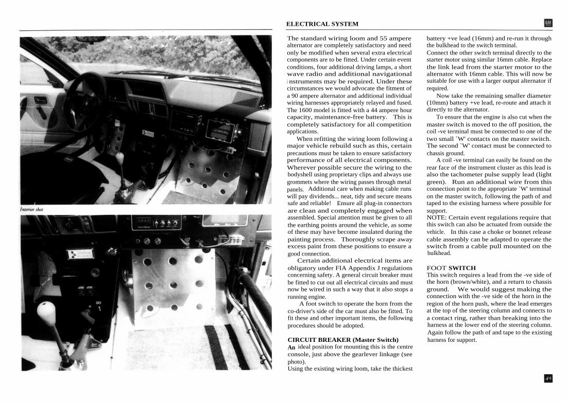
ELECTRICAL SYSTEM
The standard wiring loom and 55 amperealternator are completely satisfactory and needonly be modified when several extra electricalcomponents are to be fitted. Under certain eventconditions, four additional driving lamps, a shortwave radio and additional navigationali nstruments may be required. Under thesecircumstances we would advocate the fitment ofa 90 ampere alternator and additional individualwiring harnesses appropriately relayed and fused.The 1600 model is fitted with a 44 ampere hourcapacity, maintenance-free battery. This iscompletely satisfactory for all competitionapplications.
When refitting the wiring loom following amajor vehicle rebuild such as this, certainprecautions must be taken to ensure satisfactoryperformance of all electrical components.Wherever possible secure the wiring to thebodyshell using proprietary clips and always usegrommets where the wiring passes through metalpanels. Additional care when making cable runswill pay dividends... neat, tidy and secure meanssafe and reliable! Ensure all plug-in connectorsare clean and completely engaged whenassembled. Special attention must be given to allthe earthing points around the vehicle, as someof these may have become insulated during thepainting process. Thoroughly scrape awayexcess paint from these positions to ensure agood connection.
Certain additional electrical items areobligatory under FIA Appendix J regulationsconcerning safety. A general circuit breaker mustbe fitted to cut out all electrical circuits and mustnow be wired in such a way that it also stops arunning engine.
A foot switch to operate the horn from theco-driver's side of the car must also be fitted. Tofit these and other important items, the followingprocedures should be adopted.
CIRCUIT BREAKER (Master Switch)An ideal position for mounting this is the centreconsole, just above the gearlever linkage (seephoto).Using the existing wiring loom, take the thickest
battery +ve lead (16mm) and re-run it throughthe bulkhead to the switch terminal.Connect the other switch terminal directly to thestarter motor using similar 16mm cable. Replacethe link lead from the starter motor to thealternator with 16mm cable. This will now besuitable for use with a larger output alternator ifrequired.
Now take the remaining smaller diameter(10mm) battery +ve lead, re-route and attach itdirectly to the alternator.
To ensure that the engine is also cut when themaster switch is moved to the off position, thecoil -ve terminal must be connected to one of thetwo small `W' contacts on the master switch.The second `W' contact must be connected tochassis ground.
A coil -ve terminal can easily be found on therear face of the instrument cluster as this lead isalso the tachometer pulse supply lead (lightgreen). Run an additional wire from thisconnection point to the appropriate `W' terminalon the master switch, following the path of andtaped to the existing harness where possible forsupport.NOTE: Certain event regulations require thatthis switch can also be actuated from outside thevehicle. In this case a choke or bonnet releasecable assembly can be adapted to operate theswitch from a cable pull mounted on thebulkhead.
FOOT SWITCHThis switch requires a lead from the -ve side ofthe horn (brown/white), and a return to chassisground. We would suggest making theconnection with the -ve side of the horn in theregion of the horn push, where the lead emergesat the top of the steering column and connects toa contact ring, rather than breaking into theharness at the lower end of the steering column.Again follow the path of and tape to the existingharness for support.
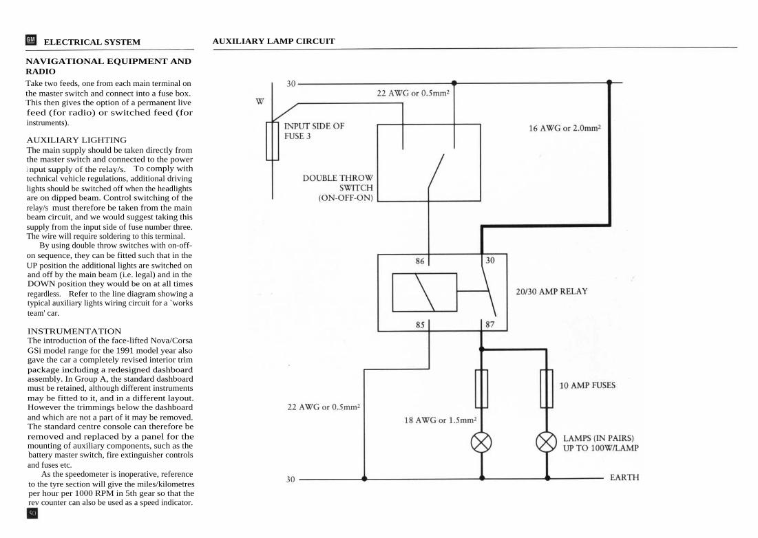
ELECTRICAL SYSTEM
NAVIGATIONAL EQUIPMENT ANDRADIO
Take two feeds, one from each main terminal onthe master switch and connect into a fuse box.This then gives the option of a permanent livefeed (for radio) or switched feed (forinstruments).
AUXILIARY LIGHTINGThe main supply should be taken directly fromthe master switch and connected to the poweri nput supply of the relay/s. To comply withtechnical vehicle regulations, additional drivinglights should be switched off when the headlightsare on dipped beam. Control switching of therelay/s must therefore be taken from the mainbeam circuit, and we would suggest taking thissupply from the input side of fuse number three.The wire will require soldering to this terminal.
By using double throw switches with on-off-on sequence, they can be fitted such that in theUP position the additional lights are switched onand off by the main beam (i.e. legal) and in theDOWN position they would be on at all timesregardless. Refer to the line diagram showing atypical auxiliary lights wiring circuit for a `worksteam' car.
INSTRUMENTATIONThe introduction of the face-lifted Nova/CorsaGSi model range for the 1991 model year alsogave the car a completely revised interior trimpackage including a redesigned dashboardassembly. In Group A, the standard dashboardmust be retained, although different instrumentsmay be fitted to it, and in a different layout.However the trimmings below the dashboardand which are not a part of it may be removed.The standard centre console can therefore beremoved and replaced by a panel for themounting of auxiliary components, such as thebattery master switch, fire extinguisher controlsand fuses etc.
As the speedometer is inoperative, referenceto the tyre section will give the miles/kilometresper hour per 1000 RPM in 5th gear so that therev counter can also be used as a speed indicator.
AUXILIARY LAMP CIRCUIT

ELECTRICAL PARTS LIST

ELECTRICAL WIRING DIAGRAM
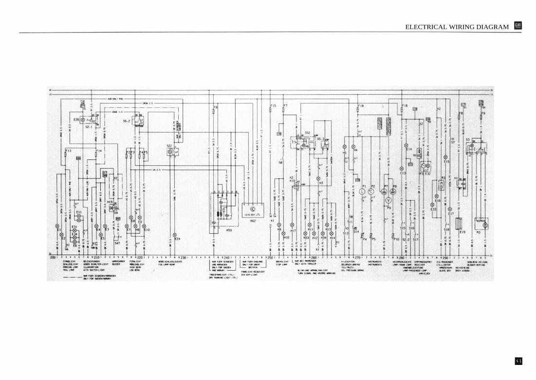
ELECTRICAL WIRING DIAGRAM
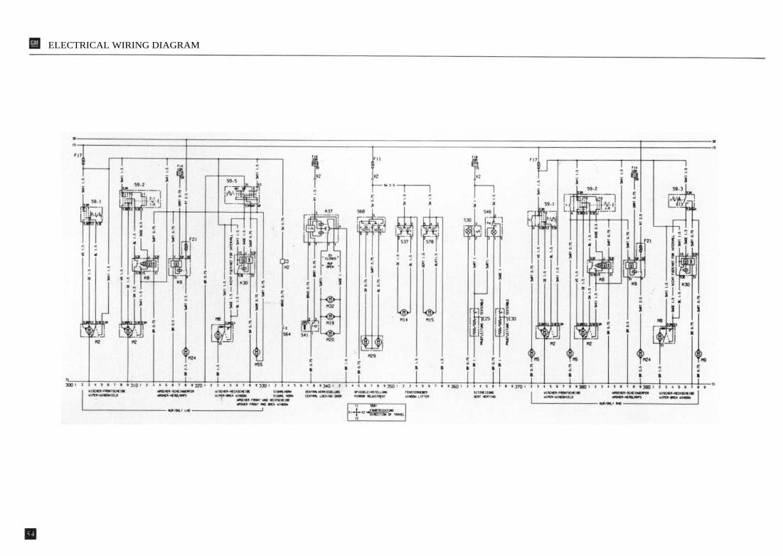
ELECTRICAL WIRING DIAGRAM
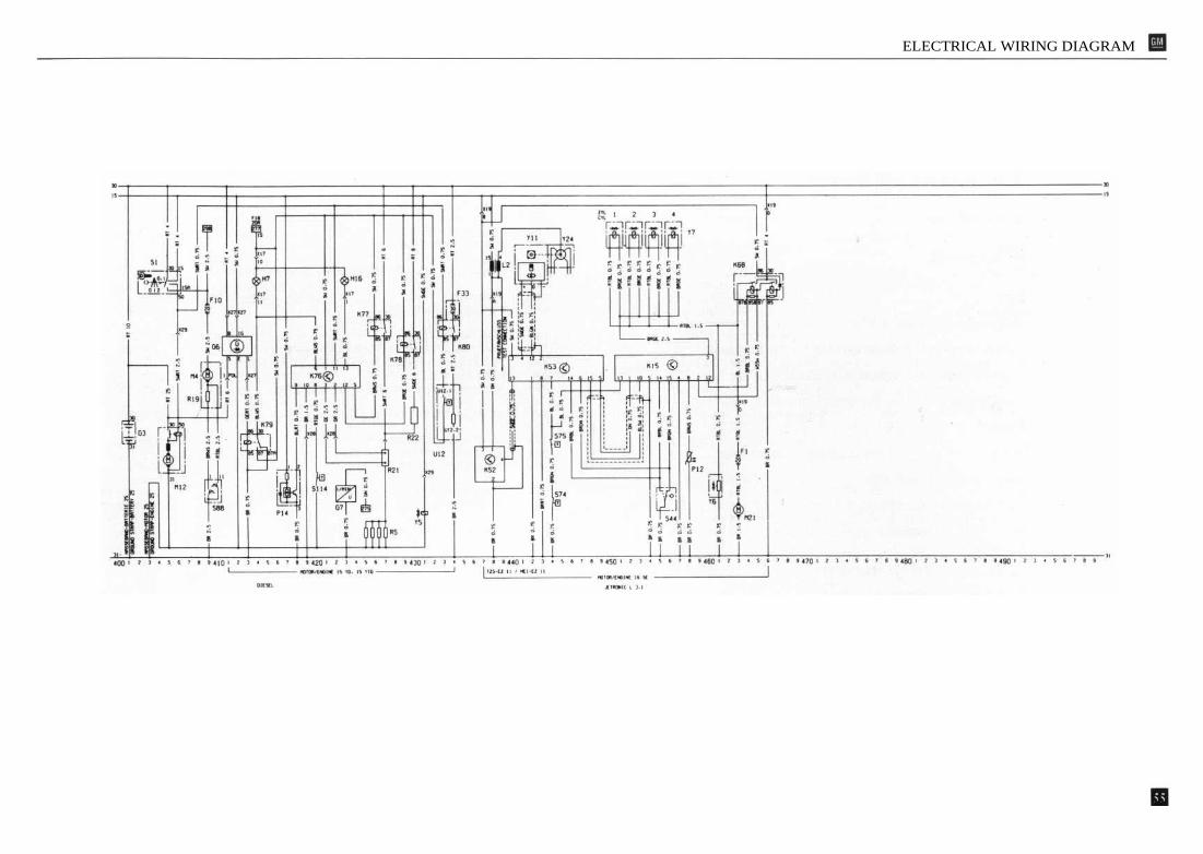
ELECTRICAL WIRING DIAGRAM

ELECTRICAL WIRING DIAGRAM

ELECTRICAL WIRING DIAGRAM

ELECTRICAL WIRING DIAGRAM

GROUP N GUIDELINES
A Group N car is fundamentally a standardproduction car fitted with obligatory additionalsafety items such as a roll cage, safety harnessesand plumbed-in fire extinguishers, to complywith specific FIA Regulations for Touring Cars -Group N. In addition you will have to carry outsome further permitted modifications to makethe car more competitive.
Starting with the engine, not a great deal canbe done to a normally aspirated engine underGroup N regulations apart from blueprinting,which is not cost effective. The basic enginedesign and component finish is to such a highstandard that the need for excessive individualcomponent preparation is minimal. However,there is some scope for a power increase as aresult of re-programming the ignition and fuelelectronic control units, and these modifiedcomponents are now generally available on theaftermarket.
Suspension modifications are permitted, inthat the springs and shock absorbers may bereplaced with uprated units, but their workingprinciple and attachment points must remainunchanged. The ride height of the vehicle mustconform to the homologated dimensions.Flexible bushes at the suspension pivot pointsmay be changed for mechanically similar bushes,but made from a harder compound.
The dimensions of the brakes must remain asnormal production specification for the modelbut the pad/lining material can be changed. Thehandbrake may be converted to 'fly-off' actionand aviation type brake lines are permitted, butno form of brake balance adjustment is allowed.
The exhaust system can be modified from thefirst silencer box to the exit, provided that thepipe size does not exceed that forward of the firstsilencer box.
BODYSHELLThe reinforcement procedures and the bodystrengthening components featured in the GroupA Kit, outlined earlier in this manual for theGroup A car can be followed, as seam weldingand strengthening of the suspended part isallowed under Group N regulations. Please note
that the carpet and gearlever gaiter supportsreferred to in that section CANNOT beremoved. The seat mounting system can bemodified to accept seats from a different source,but the alternative seats must have at least thesame MINIMUM weight as the original seats.This can be achieved by ballasting if necessary.Ballast must be securely attached to thereplacement seats for both safety and eligibilityreasons. All the interior trim must be fitted to thecar, including the rear seats, although they maynot necessarily function as a seat once the rollcage is installed!
ROLL CAGEThe Group A Clubman Kit safety roll cage canbe fitted, and holes through the trim panels canbe made if necessary to enable this component tobe attached. The section in this manualspecifically outline the fitting procedure for theGroup A car, but applies equally for a Group Ninstallation.
A front suspension brace is permittedbetween the suspension mounting points oncondition that it is fixed exclusively by bolts onto the suspension mounting points.
ELECTRICALThis section of the manual applies equally toGroup N preparation. Brakes, transmission,exhaust, suspension and engine preparationchapters are exclusively for the Group A car andhave no compatibility with the requirements ofGroup N.
GM Eurosport do not have any specificcomponents for the Group N car, althoughcertain components from the Group A ClubmansKit can be used. These are restricted to thefollowing parts:Body Strengthening KitFuel tank GuardStrut brace (tube), Strutbrace brackets LH/RHRoll cage assemblyRear beam bushesRear road springsRear shock absorbersEngine mounting rubbers (set of 3)

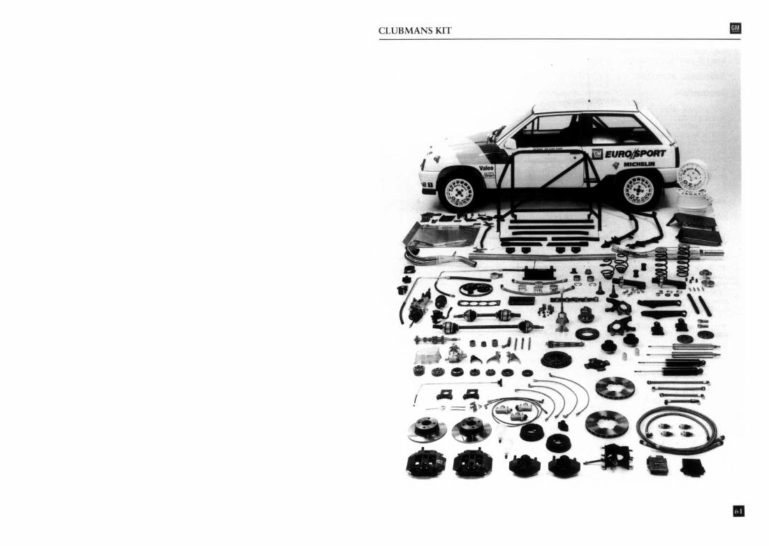
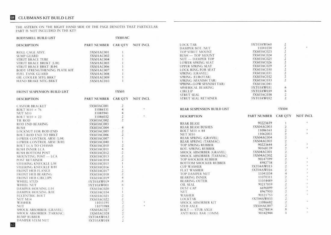
CLUBMANS KIT BUILD LIST

CLUBMANS KIT BUILD LIST

CLUBMANS KIT BUILD LIST