complex systems operational analysis - a case study for...
TRANSCRIPT
Model-Based operational analysis for complex systems -
A case study for electric vehicles
Abdelkrim Doufene
Massachusetts Institute of Technology
77 Massachusetts Ave, ESD. E40-227
Cambridge, MA 02139, USA
Hugo G. Chalé G.
ALSTOM Transport
48 rue Albert Dhalenne
93482 Saint-Ouen Cedex, France
Alain Dauron
RENAULT
1 avenue du Golf
78288 Guyancourt, France
Daniel Krob
Ecole Polytechnique
Laboratoire d’Informatique (LIX)
91128 Palaiseau Cedex, France
Published and used by INCOSE with permission.
ABSTRACT. We present in this paper an operational analysis of a complex system following a
Model Based Systems Engineering approach, illustrated by a case study on electric vehicles. We
explain some strategic issues and reasons that make electric vehicles important and complex systems,
and how these vehicles can significantly contribute to the European policies for sustainable
development. We explain why it is necessary to apply a Systems Engineering approach to deal with
the complexity of such systems, and we give an overview of the architectural design framework we
follow. We present a model of the system of interest and of its environment built from the analysis of
public documents and literature reviews. This allowed us to identify the key stakeholders, external
interfaces, needs, use cases and operational scenarios. Based on this operational analysis, we present
ways to pursue functional and trade-off analyses.
Introduction
Electric vehicles (EVs) appear as revolutionary and beneficial innovations especially from an
environmental point of view. The emergence of new services associated to electric mobility requires
considering a larger area of interests mixing, at the very least, vehicles and infrastructure. Many more
stakeholders and enabling systems are involved in the EVs` environment, and the lifecycles of the
latter are largely independent and asynchronous.
Our study aims at applying modern Model Based Systems Engineering (MBSE) techniques (see
[Estefan, 2007] for example) and the best practices identified during industrial systems development
projects in order to improve product performance and quality, and to reduce the engineering costs.
We conduct a case study for EVs. We focus in this article on an operational analysis following an
instantiation of a generic complex systems engineering method, using the OMG Systems Modeling
Language (OMG SysML™)1 [Friedenthal, 2008; Weilkiens, 2008], as explained in [Krob, 2009 and
2010].
One of the advantages of using the techniques of systems engineering (SE) is to apply a holistic
1 The OMG systems Modeling Language (OMG SysML™), http://www.omgsysml.org/
approach to the problem in order to have the most complete possible design. Given the complexity of
our system of interest, the objective in this paper is not to present the complete design, but to focus on
an operational analysis through enough examples to understand our approach. The examples we
present are meant to be illustrative and not exhaustive. They are chosen mainly to study the
Use/Exploitation phase of the EV lifecycle that highlights major new features of the EV innovation
related to the reduction of energy consumption and carbon dioxide (CO2) emissions.
The first part of the paper gives a global preview of our approach. In Section 2, we begin with an
overview of the background of our study and some strategic issues related to EVs, followed by the
motivation of our SE approach and a presentation of the architectural design framework used in our
study. In Section 3, we present the model of the system of interest and its environment with associated
needs and operational analyses. Finally, in Section 4, we explain the passage towards functional and
trade-off analyses and present a brief conclusion of our study.
Background
Before conducting an operational analysis, we present the background of EVs and the reasons for
which we opt for an SE approach. We give an overview of the architectural design framework that
supports the operational analysis of our system.
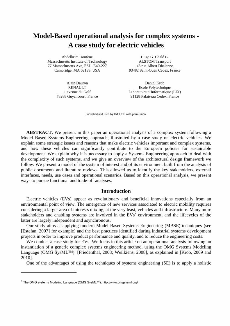
The European Commission expects that in its 27 countries, energy needs will continue to increase
up to 2030. In 2030, primary energy consumption would be 11% higher than in 2005 [EET, 2007].
We see, in Figure 1, the final energy demand by sector and note the importance of energy
consumption corresponding to the transport sector.
Figure 1. Final Energy Demand by Sector [EET, 2007]
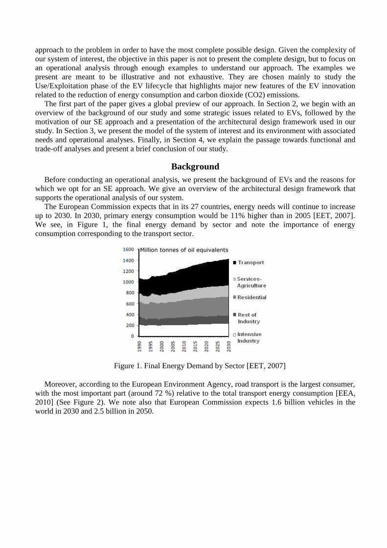
Moreover, according to the European Environment Agency, road transport is the largest consumer,
with the most important part (around 72 %) relative to the total transport energy consumption [EEA,
2010] (See Figure 2). We note also that European Commission expects 1.6 billion vehicles in the
world in 2030 and 2.5 billion in 2050.
Figure 2. Final energy consumption by mode of transport [EEA, 2010]
On the other hand, personal vehicles using internal combustion engines (ICE) are responsible for
10% of CO22 emissions in the atmosphere3. For all these reasons, EVs would be a significant
contribution to the European policies for sustainable development by reducing CO2 emissions and
non-renewable energy consumption.
Research works have been conducted in this context, to show the contribution of these vehicles in
reducing CO2 emissions and energy consumption in the USA, and associated business models. For
example, the authors of [Heywood et al., 2009] describe a set of policies needed, about personal
vehicle transportation, in order to contribute to the reduction petroleum consumption and greenhouse
gas emissions from cars and light-duty trucks in the USA over the next decades. In another example,
using a computable general equilibrium model, [Karplus, 2008] presents an evaluation of the potential
for the plug-in hybrid electric vehicle to enter the US personal vehicle market, and how this type of
vehicle can alter electricity output, refined oil consumption and CO2 emissions. A last example,
[Vogt-Schilb et al., 2009] presents a study conducted by CIRED4, focusing on macroeconomic and
macro-energetic aspects of the electric vehicle deployment. Results show that this deployment can
positively influence the economy, in particular, in scenarios considering climate policy and tensions
on oil prices, but also that the EVs allow a significant reduction on emissions from private transport.
They used a general equilibrium model that captures interactions between the dynamics of the world
economy and of technical systems.
Thus, in our case, two global measures of effectiveness (MOE) seem to rise above other criteria:
on the one hand, the protection of the environment by reducing CO2 emissions5, and, on the other
hand, minimizing the total cost of ownership of the EVs, with a reasonable driving autonomy,
compared with the ICE vehicles.
2 Carbon Dioxide.
3 Source: World Resources Institute. (cf, Vers l’automobile décartonnée, publication of La Chambre Syndicale Internationale de
l’Automobile et du Motocycle). Editions 2010. 4
CIRED: Centre International de Recherche sur l’Environnement et le Développement, http://www.centre-cired.fr/ 5 The same way for other pollutants as : Nitrogen oxide (NOx), Hydrocarbon (HC) and Carbon monoxide (CO). Source: Presentation of
Rémi Bastien, Director of the Department of Research, Advanced Engineering, and Materials at Renault: The Electric Vehicle Program of
the Renault-Nissan Alliance, in Automotive Electronics and Systems Congress
CESA, Electric and Hybrid Vehicles, Paris, November 2010.

Why use a systems engineering approach?
EVs are high-technology innovative products. The traditional vehicle architectures are not a priori
optimal solutions for the EV. New services appear and require taking into consideration the EVs and
infrastructure.
Their study needs to start from "an almost blank sheet" and to use modern methods of design given
the complexity of the problem. Indeed, numerous stakeholders (users, automotive manufacturers,
energy suppliers, telecommunication operators, parking, etc.) are involved in the EVs` environment.
Their interactions are complex and their lifecycles are largely independent and asynchronous. Other
reason that draws interest into this type of systems is the necessity to take the infrastructure into
consideration as explained in [Roos, 2004]. Also, we should not forget other factors that underlie the
success or failure of a new car program [Hanawalt, 2010].
To justify further the choice of our system of interest, we show the complex economic equation
and business model related to EVs. Given that the battery price is a significant part of the total EV
cost, one could imagine that the vehicle could be bought and the battery rented or leased. For the first
generation of EVs (meaning low production volumes), the price will be higher than for an ICE
vehicle. On the other hand, some environmental bonuses (5000 euros in France6) should have a
balanced purchasing effect and gains are expected in use thanks to the price of electric energy (see
Figure 3). The business model becomes more complex given that the prices of energy may drastically
change during the day, and that some value is attached to the ability to level energy demands on the
energy network (see for example [Kempton, 2005] about “Vehicle to grid” interactions).
Figure 3. The costs of purchase and use: comparison between ICE and Electric Vehicles7.
Given what has been previously exposed, and in order to deal with the complexity of our system of
interest, we follow a SE approach. As defined in [INCOSE, 2010], “Systems engineering is an
interdisciplinary approach and means to enable the realization of successful systems. It focuses on
defining customer needs and required functionality early in the development cycle, documenting
requirements, and then proceeding with design synthesis and system validation while considering the
complete problem: operations, cost and schedule, performance, training and support, test,
manufacturing, and disposal. SE considers both the business and the technical needs of all customers
with the goal of providing a quality product that meets the user needs.”
6 Source: France Government web site. January 2011.
http://www.gouvernement.fr/gouvernement/achats-de-vehicules-neufs-refonte-du-dispositif-de-bonus-malus-ecologique (January 2011) 7 Source: Presentation of Rémi Bastien, Director of the Department of Research, Advanced Engineering, and Materials at Renault: The
Electric Vehicle Program of the Renault-Nissan Alliance, in Automotive Electronics and Systems Congress
CESA, Electric and Hybrid Vehicles, Paris, November 2010.
Additionally, given the ecologic and economic purpose of EVs, we refer to some basic principles
explained in [Sage, 1997 and 1998] showing the key role of SE and management to achieving
industrial ecology and sustainable development. For further details, the reader can refer to [INCOSE,
2010; Sage, 2000, 2005 and 2009; Meinadier, 1998; Blanchard, 1998; Buede, 2009; Honour, 2004].
Our systems architectural design framework
When we follow a SE approach, we often use an architectural framework that provides guidance
and rules for structuring, classifying and organizing architectures [Cloutier, 2010]. For example, we
may cite U.S. Department of Defense Architecture Framework (DODAF)8 and the UK Ministry of
Defense Architecture Framework (MODAF)9. See also [Richards, 2006] for more examples.
A framework serves as a reference to organize all the components of the architecture of a system
with several viewpoints. Architectural views are important to cover all the scope of the system
architecture. The principle of views was first proposed by [Zachman, 1987].
We will use here a framework inspired by the SAGACE method originally proposed in [Penalva,
1997]. SAGACE revolves around three main principles: a modeling approach; a representation of
views (a matrix of nine points of view); and a graphical modeling language. In order to achieve a
complete modeling of a system, it advocates studying the system in steps in an iterative manner. The
various steps highlight elements like issues and system environment, project purpose and missions,
stakeholders, etc. Once these elements are clearly identified, we can then design the system and
describe it in the matrix of nine points of view: Operational, Functional and Structural viewpoints, all
refined by three time perspectives [Benkhannouchel, 1993; Chatel, 2004; Meinadier, 1998 and 2002].
In our study, we will also use these three main viewpoints of analysis, refined, however, by
behavioral - and not by time as in SAGACE – perspectives, which is well supported by the SysML
modeling language as explained in [Krob, 2009 and 2010], [Chale et al., 2012] and [Doufene et al.,
2012 and 2013].
• The Operational viewpoint aims to define WHY the system, i.e. to specify the relationships
between the system and its environment, that is to say the system's mission and the services it offers.
• The Functional viewpoint aims to explain the system`s logical functioning, i.e. WHAT has to be
done, not considering how it will be realized.
• The Structural viewpoint that defines HOW the system is realized, i.e. physical components
(hardware, software and humans) organized to implement the system.
Environment and operational analysis
As explained previously, the EVs are surrounded by a systemic environment where everything
evolves over time. However, some elements of the system of interest, like the systems’ missions,
external interfaces, and use cases, etc. should be invariants. In order to find the invariants of our
system of interest, the first step is to identify external interfaces, by modeling the system`s
environment and analyzing needs. Thus, we can specify most clearly the systems’ missions.
We present, in this section, our system of interest and propose a modeling of its environment. We
present a needs analysis and an operational analysis by showing the EV and some external systems
operational contexts, use cases and scenarios (examples mainly focus on the relation to energy
consumption).
8 http://cio-nii.defense.gov/sites/dodaf20/. 9 http://www.mod.uk/DefenceInternet/AboutDefence/WhatWeDo/
InformationManagement/MODAF/ accessed January 2011.

Which system are we talking about?
Our system of interest is the electric vehicle (EV). We define an EV as a vehicle that uses electric
motors for propulsion, powered by an on-board battery pack. The EV communicates with the
charging station and exchanges messages with some stakeholder via an Information and
Communication System in order to process information such as its state of charge and billing.
The automotive manufacturer Renault targets a market of 10% in the world for EVs in ten years.
The target market represents, mainly, vehicle owners for whom autonomy is not a particular problem,
given their daily usage and daily driving distances. This represents over 70% of market share,10
considering for instance that 87% of Europeans drive less than 60 kilometers daily11.
Figure 4. An electric vehicle.
Modelling the system environment
As explained previously, one of the most important points in an SE approach is the management of
the interfaces. Indeed, it is crucial to delimit the system of interest from systems with which it
interacts to prevent any evolution that could affect the other systems or the overall system behavior.
This delimitation allows having the clearest possible view of external interfaces of the system of
interest before diving into the optimization of its internal interfaces. To achieve this delimitation, we
propose a modeling of the EVs` environment.
We analyzed public documents and conducted literature reviews to study the EVs` environment.
This allowed us to identify a set of stakeholders and highlight important external interfaces. Indeed,
numerous stakeholders (customers, users, automotive manufacturers, energy suppliers, financial
institutions, telecommunication operators, parking, etc.) are involved in the EVs` environment. Given
the long list of external systems, and in order to be unambiguous, we organized them in seven high-
level external systems (or categories) according to the role of each external system in relation to the
system of interest (see Figure 5).
10 Interview of Renault-Nissan CEO Carlos Ghosn, September 30th 2010. http://www.rtl.fr/actualites/vie-pratique/article/carlos-ghosn-au-
mondial-de-l-auto-renault-lance-les-commandes-des-voitures-electriques-5953121278. 11
Source: Presentation of Rémi Bastien, Director of the Department of Research, Advanced Engineering, and Materials at Renault: The
Electric Vehicle Program of the Renault-Nissan Alliance, in Automotive Electronics and Systems Congress
CESA, Electric and Hybrid Vehicles, Paris, November 2010.
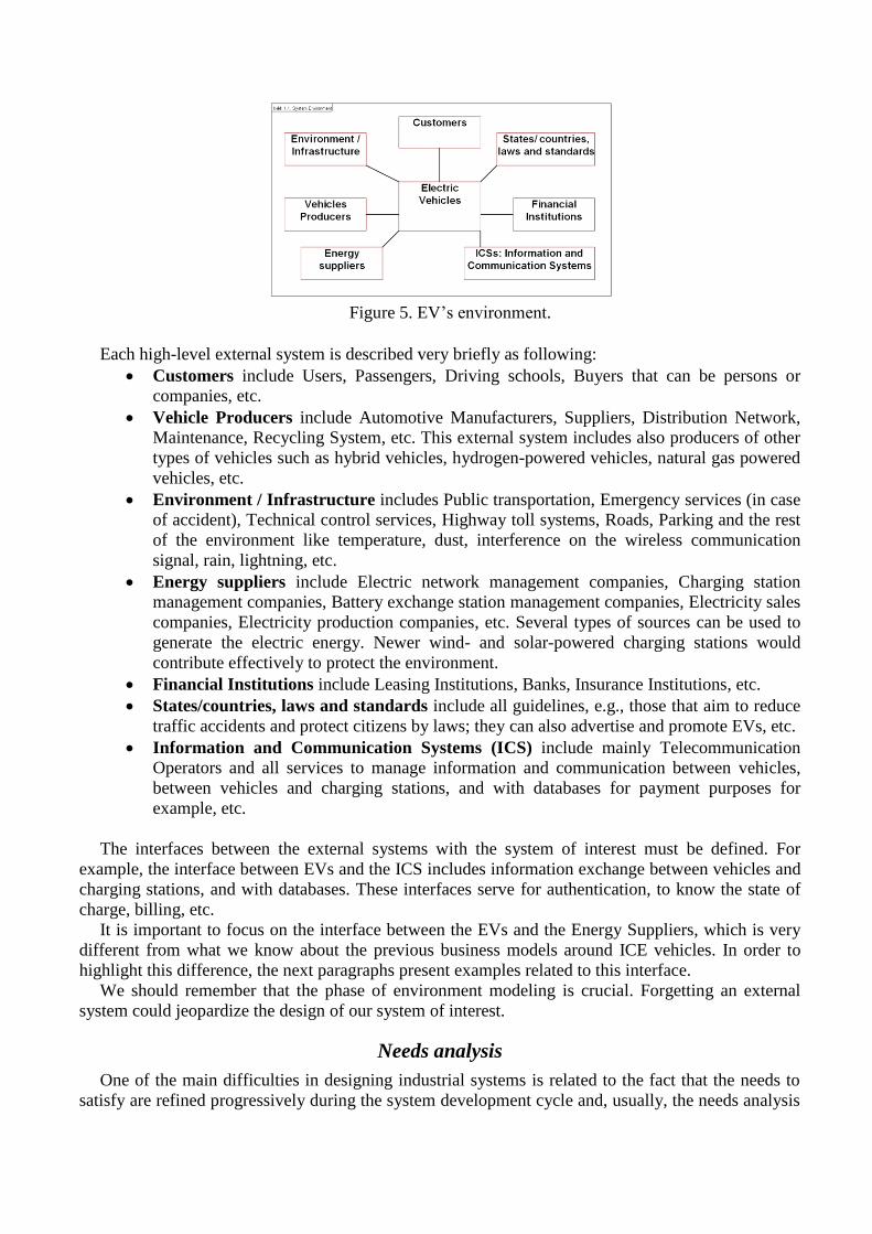
Figure 5. EV’s environment.
Each high-level external system is described very briefly as following:
Customers include Users, Passengers, Driving schools, Buyers that can be persons or
companies, etc.
Vehicle Producers include Automotive Manufacturers, Suppliers, Distribution Network,
Maintenance, Recycling System, etc. This external system includes also producers of other
types of vehicles such as hybrid vehicles, hydrogen-powered vehicles, natural gas powered
vehicles, etc.
Environment / Infrastructure includes Public transportation, Emergency services (in case
of accident), Technical control services, Highway toll systems, Roads, Parking and the rest
of the environment like temperature, dust, interference on the wireless communication
signal, rain, lightning, etc.
Energy suppliers include Electric network management companies, Charging station
management companies, Battery exchange station management companies, Electricity sales
companies, Electricity production companies, etc. Several types of sources can be used to
generate the electric energy. Newer wind- and solar-powered charging stations would
contribute effectively to protect the environment.
Financial Institutions include Leasing Institutions, Banks, Insurance Institutions, etc.
States/countries, laws and standards include all guidelines, e.g., those that aim to reduce
traffic accidents and protect citizens by laws; they can also advertise and promote EVs, etc.
Information and Communication Systems (ICS) include mainly Telecommunication
Operators and all services to manage information and communication between vehicles,
between vehicles and charging stations, and with databases for payment purposes for
example, etc.
The interfaces between the external systems with the system of interest must be defined. For
example, the interface between EVs and the ICS includes information exchange between vehicles and
charging stations, and with databases. These interfaces serve for authentication, to know the state of
charge, billing, etc.
It is important to focus on the interface between the EVs and the Energy Suppliers, which is very
different from what we know about the previous business models around ICE vehicles. In order to
highlight this difference, the next paragraphs present examples related to this interface.
We should remember that the phase of environment modeling is crucial. Forgetting an external
system could jeopardize the design of our system of interest.
Needs analysis
One of the main difficulties in designing industrial systems is related to the fact that the needs to
satisfy are refined progressively during the system development cycle and, usually, the needs analysis
stabilizes late in the design cycle. We present first here some examples of macro-needs that we will
refine later for the explanation purpose.
Table I: Macro-needs examples.
(1) The user expects that the EV's purpose is zero emission of CO2.
(2) The user needs to be reassured by usage support and assistance.
(3) The user wants powerful and safe EVs.
(4) The user wants to be able to supply the vehicle with energy.
(5) The automotive manufacturer wants the EV to attract a large number of customers.
(6) The automotive manufacturer wants to explain the environment-friendly performance to the
customers combined with the economic opportunity and unique services.
By analyzing the macro-needs in the Table I, we can refine some of them. For example, the macro-
need (3) may be refined as following.
Table II: Refinement of the macro-need (3) “powerful and safe EVs”.
The user wants to receive a very quick response to an acceleration or deceleration request.
The user wants good acceleration level when fully pressing the accelerator pedal
The user does not want to feel the physical limitations of the EV`s autonomy.
The user wants the maximum speed not to exceed a defined safety threshold.
The user wants a completely safe behavior in respect to electric risk.
The macro-need (4) is another example that has a major impact on the management of the interface
between the EVs and the Energy Suppliers. We can refine it as following.
Table III: Refinement of the macro-need (4) “supply with energy”.
The user wants to recharge or/and exchange the battery automatically.
The user wants to recharge the EV at home and at work, in parking during shopping, at public
charging stations or at fast charging stations.
The user does not want to waste time when recharging the EV battery.
Another example of refinement is to limit the economic risk perceived by customer by the
introduction of a government bonus for purchasing an EV. Additionally environmental regulations
and automotive standards impose other constraints.
Finally, as we said previously, we have to continue the needs analysis and refinement until we
have clear, precise and measurable needs. We could also note also that we can organize the macro-
needs following a framework like PESTEL for "Political, Economic, Social, Technological,
Environmental and Legal". [PESTEL, 2007].
Operational analysis
As explained previously, the operational analysis aims to specify the system's missions and the
utility of the system. First, we synthesize the operational contexts of the system of interest and those
of the external systems; then we analyze use cases and scenarios.
An operational context of a system is a state in which it can operate. An operational contexts
diagram presents all the possible operational contexts of the system and the transitions between them.
The study of operational contexts aims to have a global view of all the situations which we have to
consider, by combining the states of the system of interest and those of external systems. The purpose
is to answer the question: given a context, what shall the system do and/or how shall the system be
realized in order to operate in its environment. State is the technical term used to model a context in
the SysML state machine diagrams. We can represent the context diagram using state transition
diagram. Within the context diagram, the state boxes represent the states of system of interest or
external systems.
So, we consider static and dynamic views of analysis. A Use Case is a refinement of a context in
which we describe statically external systems involved in a given context and the nature of their
interactions with the system of interest. A scenario is a refinement of a use case (and thus of the
associated context) in which we describe dynamically the interactions between the external systems
involved in a given context and the system of interest.
In the following, we present the EV`s operational contexts, examples of external systems`
operational contexts and some use cases and scenarios. We use SysML diagrams [Friedenthal, 2008;
Weilkiens, 2008]. As explained in [Krob, 2009 and 2010][Doufene, 2013], to describe the operational
contexts we use State Machine diagrams, for describing the use cases we use Use Case diagrams, and
for the scenarios we use Sequence diagrams. We use, as a modeler, the Artisan Studio software12.
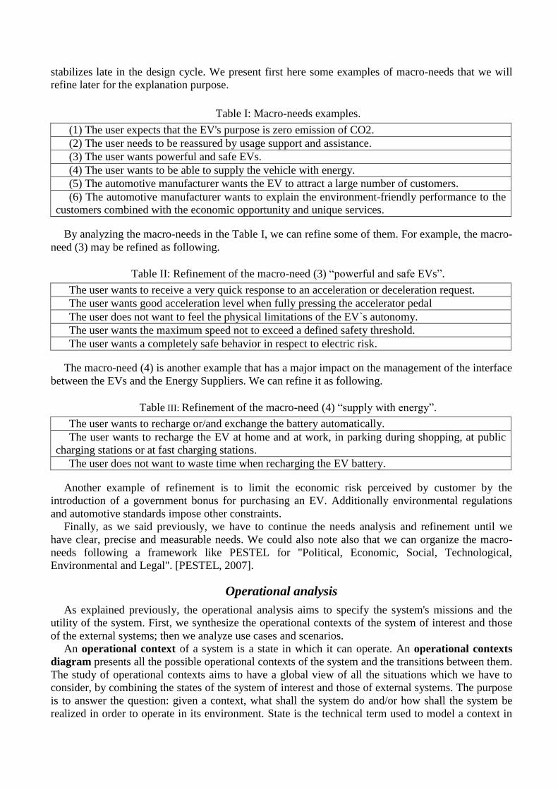
EV operational contexts. The study of the operational contexts of the system of interest must retrace
its lifecycle. We begin with the main EV`s lifecycle phases: Design, Production, Distribution /
Commercialization, Use / Exploitation, Maintenance / Reparation and Recycling. Then, we detail all
the phases. In the Figure 6, we present the possible EV`s states. For example, in the Use/Exploitation
phase, we show the EV’s states: the vehicle is discharged (not enough energy to run), the vehicle is
connected to the Electric Network (in order to be recharged) and the vehicle is charged (running or
parked).
Figure 6. EV`s operational contexts.
Once the EV`s operational contexts are defined, we study the operational contexts of the external
systems. Indeed, to have a complete analysis, we have to study the system of interest by combining its
states and those of the external systems.
External systems contexts. Unlike the operational contexts of the system of interest, in external
systems contexts analysis, we only show the external systems` states that are directly concerned with
the system of interest, not all the external systems` lifecycles. We present two examples that are
12 http://www.artisansoftwaretools.com/studiouno
useful to learn more about the interface between the EVs and the Energy Suppliers. We focus only on
the external system “Electric Network” that is included in the high-level external system “Energy
Suppliers.” The examples are also sufficient to understand our approach and the rest of our study.
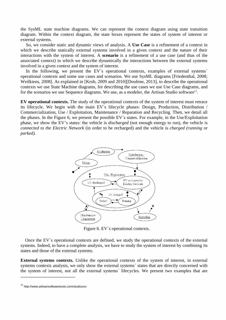
Electric Network operational contexts. The Electric Network (EN) is a sub-system of the high-level
external system “Energy Suppliers.” The EN interacts with the EV in its state “connected to EN.”
Therefore, we focus only on the EN states concerned, not all the lifecycle of the EN. These states are
EN is not functional and EN is functional (normal demand or peak of demand).
Figure 7. EN`s operational contexts.
ICS operational contexts. The ICS can be available or not, due to the states of the sub-systems. The
detail level of these operational contexts, shown in Figure 8, is sufficient and it is not necessary, in
this paper, to detail them.
Figure 8. ICS`s operational contexts.
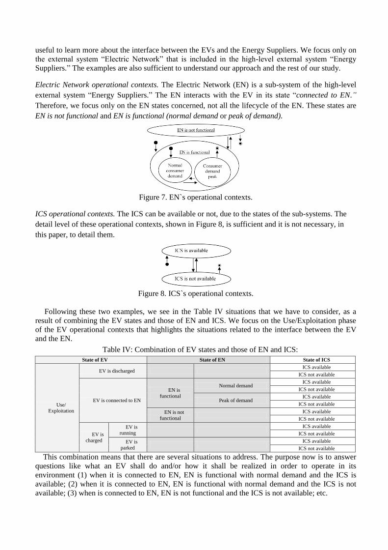
Following these two examples, we see in the Table IV situations that we have to consider, as a
result of combining the EV states and those of EN and ICS. We focus on the Use/Exploitation phase
of the EV operational contexts that highlights the situations related to the interface between the EV
and the EN.
Table IV: Combination of EV states and those of EN and ICS:
State of EV State of EN State of ICS
Use/
Exploitation
EV is discharged ICS available
ICS not available
EV is connected to EN
EN is
functional
Normal demand ICS available
ICS not available
Peak of demand ICS available
ICS not available
EN is not
functional
ICS available
ICS not available
EV is
charged
EV is running
ICS available
ICS not available
EV is
parked
ICS available
ICS not available
This combination means that there are several situations to address. The purpose now is to answer
questions like what an EV shall do and/or how it shall be realized in order to operate in its
environment (1) when it is connected to EN, EN is functional with normal demand and the ICS is
available; (2) when it is connected to EN, EN is functional with normal demand and the ICS is not
available; (3) when is connected to EN, EN is not functional and the ICS is not available; etc.
All possible questions aim to make a complete design of the system of interest. Obviously, we have
to take into consideration all the operational contexts of all the external systems and the events that
trigger the transitions between the contexts of each external system, but that is not our purpose in this
paper. The next step is to refine all these operational contexts statically by use cases and dynamically
by scenarios. This step is important to move towards functional and structural analyses that aim,
respectively, to describe what the system shall do, and how the system shall be realized to operate in
its environment, considering each possible operational context.
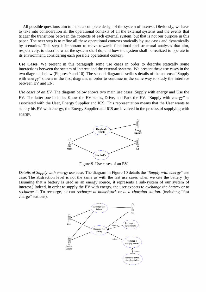
Use Cases. We present in this paragraph some use cases in order to describe statically some
interactions between the system of interest and the external systems. We present these use cases in the
two diagrams below (Figures 9 and 10). The second diagram describes details of the use case ”Supply
with energy” shown in the first diagram, in order to continue in the same way to study the interface
between EV and EN.
Use cases of an EV. The diagram below shows two main use cases: Supply with energy and Use the
EV. The latter one includes Know the EV states, Drive, and Park the EV. “Supply with energy” is
associated with the User, Energy Supplier and ICS. This representation means that the User wants to
supply his EV with energy, the Energy Supplier and ICS are involved in the process of supplying with
energy.
Figure 9. Use cases of an EV.
Details of Supply with energy use case. The diagram in Figure 10 details the “Supply with energy” use
case. The abstraction level is not the same as with the last use cases when we cite the battery (by
assuming that a battery is used as an energy source, it represents a sub-system of our system of
interest.) Indeed, in order to supply the EV with energy, the user expects to exchange the battery or to
recharge it. To recharge, he can recharge at home/work or at a charging station. (including “fast
charge” stations).
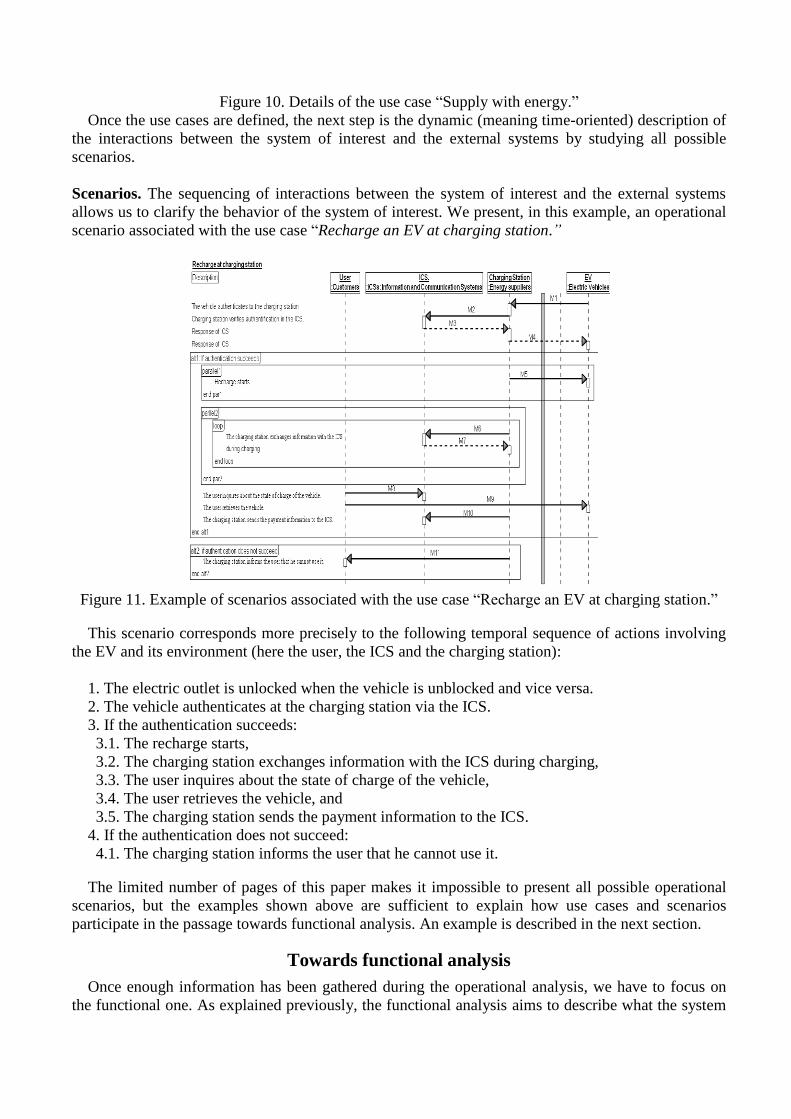
Figure 10. Details of the use case “Supply with energy.”
Once the use cases are defined, the next step is the dynamic (meaning time-oriented) description of
the interactions between the system of interest and the external systems by studying all possible
scenarios.
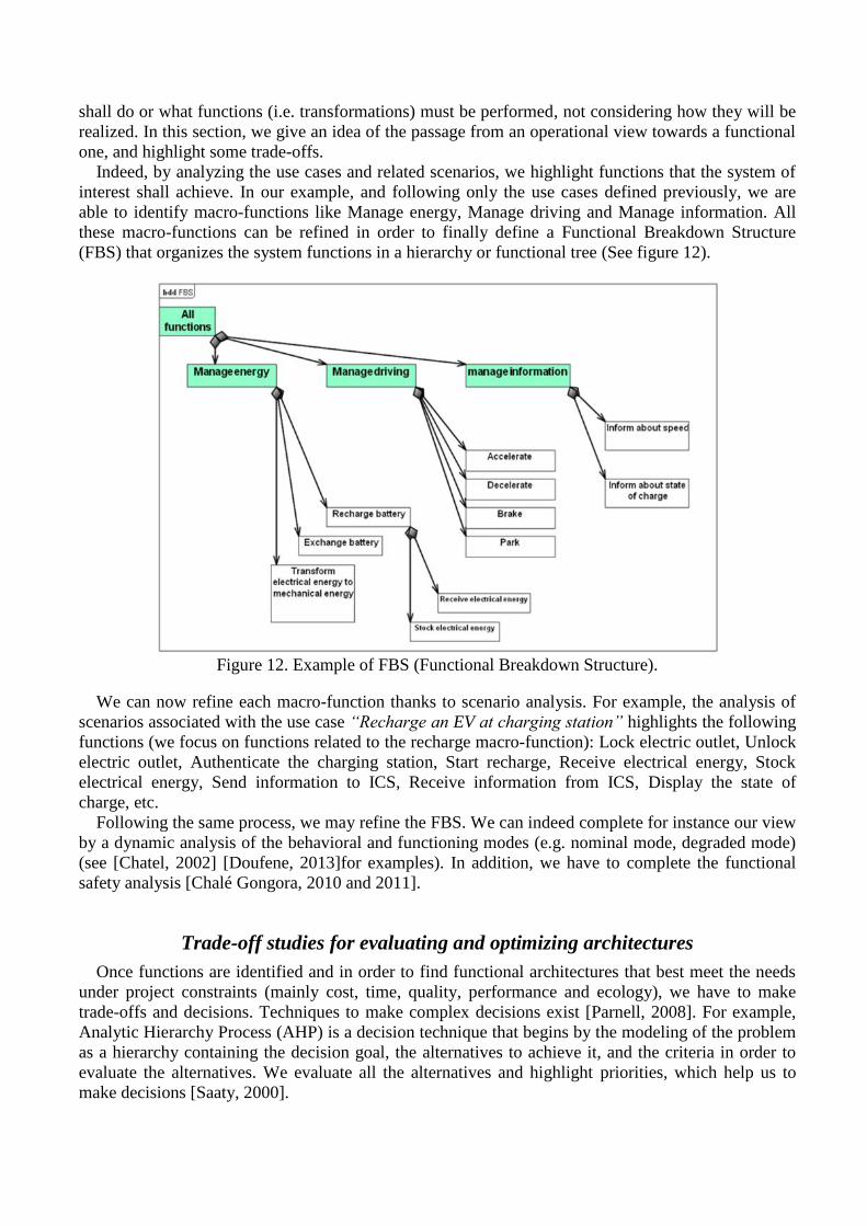
Scenarios. The sequencing of interactions between the system of interest and the external systems
allows us to clarify the behavior of the system of interest. We present, in this example, an operational
scenario associated with the use case “Recharge an EV at charging station.”
Figure 11. Example of scenarios associated with the use case “Recharge an EV at charging station.”
This scenario corresponds more precisely to the following temporal sequence of actions involving
the EV and its environment (here the user, the ICS and the charging station):
1. The electric outlet is unlocked when the vehicle is unblocked and vice versa.
2. The vehicle authenticates at the charging station via the ICS.
3. If the authentication succeeds:
3.1. The recharge starts,
3.2. The charging station exchanges information with the ICS during charging,
3.3. The user inquires about the state of charge of the vehicle,
3.4. The user retrieves the vehicle, and
3.5. The charging station sends the payment information to the ICS.
4. If the authentication does not succeed:
4.1. The charging station informs the user that he cannot use it.
The limited number of pages of this paper makes it impossible to present all possible operational
scenarios, but the examples shown above are sufficient to explain how use cases and scenarios
participate in the passage towards functional analysis. An example is described in the next section.
Towards functional analysis
Once enough information has been gathered during the operational analysis, we have to focus on
the functional one. As explained previously, the functional analysis aims to describe what the system
shall do or what functions (i.e. transformations) must be performed, not considering how they will be
realized. In this section, we give an idea of the passage from an operational view towards a functional
one, and highlight some trade-offs.
Indeed, by analyzing the use cases and related scenarios, we highlight functions that the system of
interest shall achieve. In our example, and following only the use cases defined previously, we are
able to identify macro-functions like Manage energy, Manage driving and Manage information. All
these macro-functions can be refined in order to finally define a Functional Breakdown Structure
(FBS) that organizes the system functions in a hierarchy or functional tree (See figure 12).
Figure 12. Example of FBS (Functional Breakdown Structure).
We can now refine each macro-function thanks to scenario analysis. For example, the analysis of
scenarios associated with the use case “Recharge an EV at charging station” highlights the following
functions (we focus on functions related to the recharge macro-function): Lock electric outlet, Unlock
electric outlet, Authenticate the charging station, Start recharge, Receive electrical energy, Stock
electrical energy, Send information to ICS, Receive information from ICS, Display the state of
charge, etc.
Following the same process, we may refine the FBS. We can indeed complete for instance our view
by a dynamic analysis of the behavioral and functioning modes (e.g. nominal mode, degraded mode)
(see [Chatel, 2002] [Doufene, 2013]for examples). In addition, we have to complete the functional
safety analysis [Chalé Gongora, 2010 and 2011].
Trade-off studies for evaluating and optimizing architectures
Once functions are identified and in order to find functional architectures that best meet the needs
under project constraints (mainly cost, time, quality, performance and ecology), we have to make
trade-offs and decisions. Techniques to make complex decisions exist [Parnell, 2008]. For example,
Analytic Hierarchy Process (AHP) is a decision technique that begins by the modeling of the problem
as a hierarchy containing the decision goal, the alternatives to achieve it, and the criteria in order to
evaluate the alternatives. We evaluate all the alternatives and highlight priorities, which help us to
make decisions [Saaty, 2000].
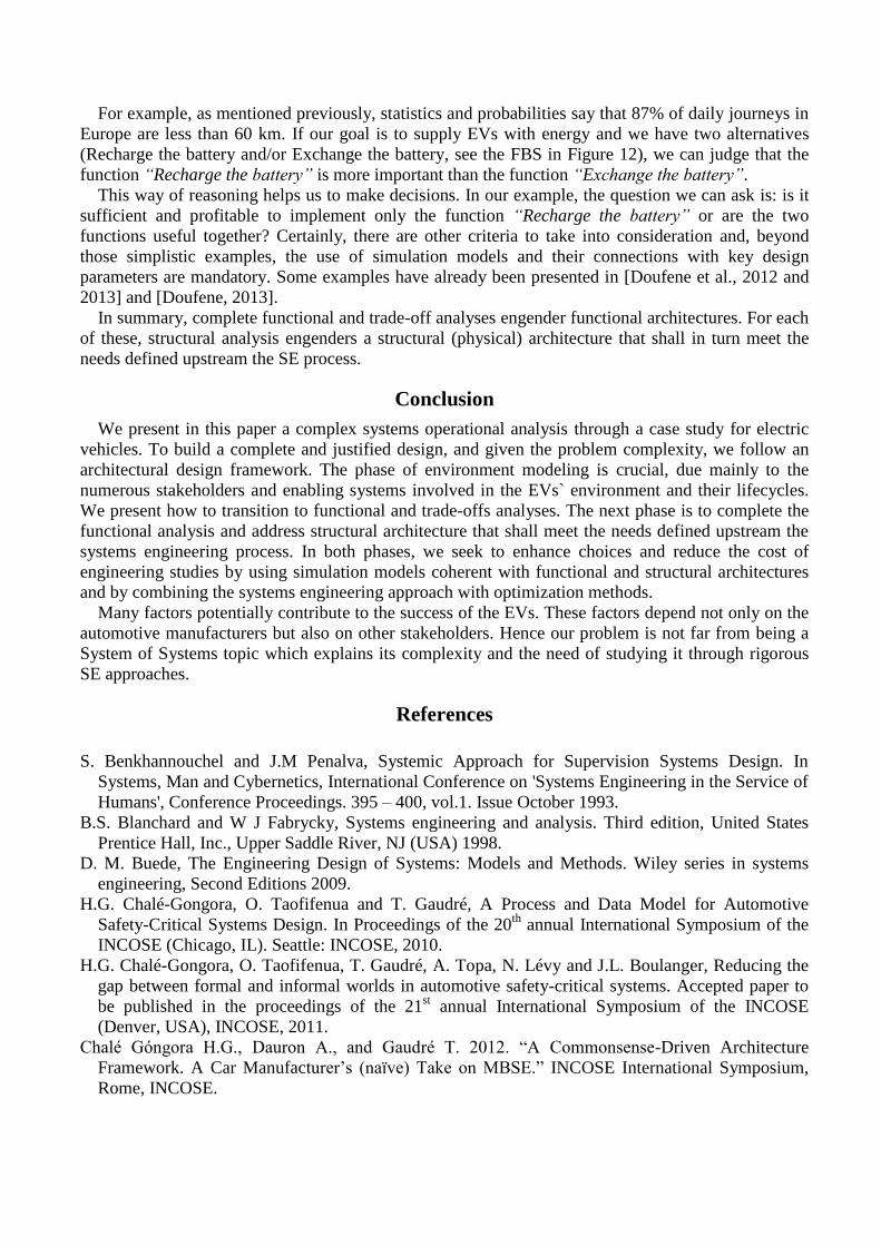
For example, as mentioned previously, statistics and probabilities say that 87% of daily journeys in
Europe are less than 60 km. If our goal is to supply EVs with energy and we have two alternatives
(Recharge the battery and/or Exchange the battery, see the FBS in Figure 12), we can judge that the
function “Recharge the battery” is more important than the function “Exchange the battery”.
This way of reasoning helps us to make decisions. In our example, the question we can ask is: is it
sufficient and profitable to implement only the function “Recharge the battery” or are the two
functions useful together? Certainly, there are other criteria to take into consideration and, beyond
those simplistic examples, the use of simulation models and their connections with key design
parameters are mandatory. Some examples have already been presented in [Doufene et al., 2012 and
2013] and [Doufene, 2013].
In summary, complete functional and trade-off analyses engender functional architectures. For each
of these, structural analysis engenders a structural (physical) architecture that shall in turn meet the
needs defined upstream the SE process.
Conclusion
We present in this paper a complex systems operational analysis through a case study for electric
vehicles. To build a complete and justified design, and given the problem complexity, we follow an
architectural design framework. The phase of environment modeling is crucial, due mainly to the
numerous stakeholders and enabling systems involved in the EVs` environment and their lifecycles.
We present how to transition to functional and trade-offs analyses. The next phase is to complete the
functional analysis and address structural architecture that shall meet the needs defined upstream the
systems engineering process. In both phases, we seek to enhance choices and reduce the cost of
engineering studies by using simulation models coherent with functional and structural architectures
and by combining the systems engineering approach with optimization methods.
Many factors potentially contribute to the success of the EVs. These factors depend not only on the
automotive manufacturers but also on other stakeholders. Hence our problem is not far from being a
System of Systems topic which explains its complexity and the need of studying it through rigorous
SE approaches.
References
S. Benkhannouchel and J.M Penalva, Systemic Approach for Supervision Systems Design. In
Systems, Man and Cybernetics, International Conference on 'Systems Engineering in the Service of
Humans', Conference Proceedings. 395 – 400, vol.1. Issue October 1993.
B.S. Blanchard and W J Fabrycky, Systems engineering and analysis. Third edition, United States
Prentice Hall, Inc., Upper Saddle River, NJ (USA) 1998.
D. M. Buede, The Engineering Design of Systems: Models and Methods. Wiley series in systems
engineering, Second Editions 2009.
H.G. Chalé-Gongora, O. Taofifenua and T. Gaudré, A Process and Data Model for Automotive
Safety-Critical Systems Design. In Proceedings of the 20th
annual International Symposium of the
INCOSE (Chicago, IL). Seattle: INCOSE, 2010.
H.G. Chalé-Gongora, O. Taofifenua, T. Gaudré, A. Topa, N. Lévy and J.L. Boulanger, Reducing the
gap between formal and informal worlds in automotive safety-critical systems. Accepted paper to
be published in the proceedings of the 21st annual International Symposium of the INCOSE
(Denver, USA), INCOSE, 2011.
Chalé Góngora H.G., Dauron A., and Gaudré T. 2012. “A Commonsense-Driven Architecture
Framework. A Car Manufacturer’s (naïve) Take on MBSE.” INCOSE International Symposium,
Rome, INCOSE.

V. Chatel, E.M El Koursi, C. Feliot and U. Huismann,.Functional analysis of the sub-system of
energy and infrastructure of conventional rail. IEEE International Conference Systems, Man and
Cybernetics, vol.3 Issue October 2002.
V. Chatel and C. Feliot, Functional analysis for safe and available system design, IEEE International
Conference Systems, Man and Cybernetics, 2004.
R. Cloutier, G. Muller, D. Verma, R. Nilchiani, E. Hole and M. Bone , The Concept of Reference
Architectures. Systems Engineering Vol. 13, No. 1, 2010.
A. Doufene. Architecture des systems complexes et optimization – Application aux vehicules
electriques. PhD thesis, Ecole Polytechnique, France, 2013.
A. Doufene, H.G. C. Gongora and D. Krob. Sharing the Total Cost of Ownership of Electric Vehicles:
A Study on the Application of Game Theory. 23rd Annual INCOSE International Symposium –
Philadelphia USA. 24-27 June, 2013.
A. Doufene, H.G. C. Gongora and D. Krob. Complex Systems Architecture Framework. Extension to
Multi-Objective Optimization. Complex Systems Design & Management. (CSDM), Paris
December 2012. proceedings "Science and Engineering" series by Springer.
EEA, Final Energy Consumption by Sector, 2010. Official document of European Environment
Agency, available on http://www.eea.europa.eu/data-and-maps/indicators/transport-final-energy-
consumption-by-mode/transport-final-energy-consumption-by-2))
EET, European Energy and Transport –Trends to 2030. European Commission- Directorate-General
for Energy and Transport. 2007.
J.A. Estefan, Survey of Model-Based Systems Engineering (MBSE) Methodologies, Report of
INCOSE MBSE Focus Group, Rev. A, May 25, 2007.
S. Friedenthal, A. Moore and R. Steiner, A practical guide to SysML - The Systems Modeling
Language, Morgan Kaufmann, 2008.
E.S. Hanawalt and W.B. Rouse, Car Wars: Factors Underlying the Success or Failure of New Car
Programs, Wiley Periodicals, Systems Engineering Vol 13, No. 4, 2010.
J. Heywood, P. Baptista, I. Berry, K. Bhatt, L. Cheah, F. Sisternes, V. Karplus, D. Keith, M. Khusid,
D. MacKenzie and J. McAulay, An Action Plan for Cars: The Policies Needed to Reduce U.S.
Petroleum Consumption and Greenhouse Gas Emissions. MIT Energy Initiative, Cambridge,
Massachusetts. December 2009.
E.C. Honour, Understanding the Value of Systems Engineering. INCOSE, 2004.
INCOSE, Systems Engineering Handbook. A guide for system lifecycle processes and activities.
International Council on Systems Engineering (INCOSE), San Diego, CA. January 2010.
V. Karplus, Prospects for Plug-In Hybrid Transportation in the United States: A General Equilibrium
Analysis. Master of Science Thesis, Technology and Policy Program, and Dept. of Civil and
Environmental Engineering, MIT, 2008.
W. Kempton and J. Tomic, Vehicle-to-grid power implementation: From stabilizing the grid to
supporting large-scale renewable energy, Journal of Power Sources, Volume 144, Issue 1, Pages
280-294, 1 June 2005.
D. Krob, Eléments d’architecture des systèmes complexes, in "Gestion de la complexité et de
l’information dans les grands systèmes critiques", A. Appriou, Ed., 179-207, CNRS Editions, 2009.
D. Krob, Enterprise Architecture, Modules 1-10, Ecole Polytechnique, 2009-2010 (personal
communication).
J.P. Meinadier, Ingénierie et intégration de systèmes, Hermès, 1998.
J.P. Meinadier, Le métier d'intégration de systèmes, Hermès-Lavoisier, 2002.
G.S. Parnell, P.J. Driscoll and D.L. Henderson, Decision Making in Systems Engineering and
Management. Wiley Series in Systems Engineering and Management, 2008.
J.M. Penalva, La modélisation par les systèmes en situations complexes, PhD Thesis, Université de
Paris 11, Orsay, France. 1997.
PESTEL, PESTEL analysis of the macro-environment. Oxford University Press. 2007.

M.G. Richards, D.E. Hastings, N.B. Shah and D.H. Rhodes, Managing Complexity with the
Department of Defense Architecture Framework: Development of a Dynamic System Architecture
Model, Conference on Systems Engineering Research, Los Angeles, CA, April 2006.
D. Roos, R. de Neufville, F. Moavenzadeh and S. Connors, The design and development of next
generation infrastructure systems, in: Systems, Man and Cybernetics, IEEE International
Conference on, Issue October 2004.
T.L. Saaty and L.G. Vargas, Models, Methods, Concepts & Applications of the Analytic Hierarchy
Process, International Series in Operations Research and Management Science, Springer; 2000.
A. P. Sage, Systems Engineering and Management for Industrial Ecology and Sustainable
Development, IEEE International Conference on Systems, Man, and Cybernetics, 'Computational
Cybernetics and Simulation'., 784 - 790 vol.1, Issue Oct. 1997.
A.P. Sage, Risk Management for Sustainable Development, IEEE International Conference on
Systems, Man, and Cybernetics,4815 - 4819 vol.5, Issue October 1998.
A.P. Sage, Systems Engineering Education, IEEE Transactions on Systems, Man and Cybernetics,
Part C Application and Reviews, Vol. 30, NO. 2, May 2000.
A.P. Sage, Systems of Systems: Architecture Based Systems Design and Integration. Presentation in
IEEE International Conference on Systems, Man, and Cybernetics, 2005.
A.P. Sage and W. B. Rouse, Handbook of Systems Engineering and Management. Wiley series in
systems engineering, second editions 2009.
A. Vogt-Schilb, O. Sassi C. Cassen and J.C. Hourcade, Electric vehicles: What economic viability
and climate benefits in contrasting futures?, Report of Centre International de Recherche sur
l’Environnement et le Développement, CIRED October 2009. (Available online on
http://www.centre-cired.fr/ IMG/pdf/ electricvehicule.pdf, accessed March 2011).
T. Weilkiens, Systems Engineering with SysML / UML – Modeling, Analysis, Design. Morgan
Kaufmann Publishers, 2008.
J.A. Zachman, A framework for information systems architecture, IBM Systems Journal, 26, (3), 276-
292, 1987.
Biography
Dr. Abdelkrim Doufene is currently (2014) a Postdoctoral Associate in the Engineering Systems
Division (ESD) at MIT. His present work focuses on the architecture of large-scale systems for water
desalination and solar energy. His research interests include architecture of complex systems, decision
and information systems, geographic information systems, multi-disciplinary analysis and
optimization, game theory, and data mining, as well as technology innovation policy.
Abdelkrim Doufene obtained a PhD from École Polytechnique in France in 2013. He completed the
ParisTech doctoral program in management at the ENPC School of International Management. He
holds a master's degree in decision and information systems from Université Paris 1 Panthéon-
Sorbonne, ESSEC and CNAM. He also graduated from École Nationale Supérieure d’Informatique in
Algeria as an information systems engineer.
He was a research engineer in the R&D department (Electric Vehicles Program) for the automotive
manufacturer Renault (2010-2013). He has also taught in various universities and schools.
Dr. Hugo Guillermo Chalé Góngora is a System Engineer at ALSTOM Transport, where he is
also supporting the development and the deployment of model-based systems engineering. He has
over twelve years of experience in the definition and tailoring of SE processes, methods and tools for
product design. His topics of interest include safety-critical systems, formal methods, architecture
description languages and, most recently, autonomous systems. Dr. Chalé is a former co-chair and
founder of the INCOSE Automotive Working Group.
Dr. Alain Dauron graduated Engineer from Ecole Polytechnique in 1984 and then obtained a PhD
degree at Université de Paris IX Dauphine in the area of Automatic Control applied to internal
combustion engine. It was his first job as a Renault research engineer, in the framework of a
collaboration with INRIA (Institut National de la Recherche en Informatique et Automatique).
He then built and led a research group in charge of Automatic control activities for R&AE projects.
After moving to Powertrain Engineering division in 1998, he had several management positions in
Powertrain Control development and tuning activities, and then he became Department leader of
powertrain control systems. Coming back to advanced engineering in 2007, he led the upstream
Systems Engineering department, aiming at applying SE in R&AE projects and at improving SE
methods & tools. From 2011 to 2013, he also led a Research project about long range mobility based
on Electric Vehicle. He is now General Manager in charge of Systems Engineering processes,
methods and tools. His main interests in Systems Engineering are Requirements engineering, Systems
V&V, SE in the context of large product lines, MBSE, and coupling of SE with
calculation/optimization.
Alain Dauron represents Renault in the AFIS (French INCOSE Chapter) Board of Directors, and is
one of the two co-chairs of the INCOSE Automotive Working Group.
Former student of Ecole Normale Supérieure, Prof. Daniel Krob got a Ph.D. (1988) and an
Habilitation (1991) in Computer Science from University Paris 7. He is Senior Researcher at the
French National Center for Scientific Research (CNRS), presently Institute Professor at Ecole
Polytechnique and head of the Dassault Aviation - DCNS - DGA - Thales - Ecole Polytechnique -
ENSTA ParisTech - Telecom ParisTech Chair "Engineering of Complex Systems" since its creation
in 2003. Daniel Krob worked in algebraic & enumerative combinatorics, algorithms for mobile
telecommunications and finite automata & formal languages, before specializing nowadays in systems
architecture, systems engineering and systems modeling. He is the author of more than 90 scientific
papers, 4 books and holds 2 patents. Daniel Krob founded and directed the "Laboratoire
d’Informatique Algorithmique: Fondements et Applications" ( LIAFA) of University Paris 7 during 6
years. He was also head, during several years, of the steering committees of two major international
conferences in combinatorics & theoretical computer science (FPSAC & STACS). Presently Daniel

Krob is chairman of the evaluation committees of the "Information Management & Modeling"
department of the French Aerospace lab (ONERA) and of the "Architecture & Evaluation of Systems
of Systems" group of the technical expertise department of the French ministry of defense (DGA). At
international level, he is also one of the 15 founding members of the Omega-Alpha honour association
in Systems Engineering.