compressible flow ch16
DESCRIPTION
Compressible flow.TRANSCRIPT

COMPRESSIBLE FLOW
This chapter deals with the thermodynamic aspects of simple compressible flows throughnozzles and passages. Several of the cycles covered in Chapter 11 have flow inside com-ponents where it goes through nozzles or diffusers. For instance, a set of nozzles inside asteam turbine converts a high-pressure steam flow into a lower pressure high-velocityflow that enters the passage between the rotating blades. After several sections, the flowgoes through a diffuser-like chamber and another set of nozzles. The flow in a fan-jet hasseveral locations where a high-speed compressible gas flows; it passes first through a dif-fuser followed by a fan and compressor, then through passages between turbine blades,and finally exits through a nozzle. A final example of a flow that must be treated as com-pressible is the flow through a turbocharger in a diesel engine; the flow continues furtherthrough the intake system and valve openings to end up in a cylinder. The proper analysisof these processes is important for an accurate evaluation of the mass flow rate, the work,heat transfer, or kinetic energy involved, and feeds into the design and operating behaviorof the overall system.
All of the examples mentioned here are complicated with respect to the flow geom-etry and the flowing media, so we will use a simplifying model. In this chapter we willtreat one-dimensional flow of a pure substance that we will also assume behaves as anideal gas for most of the developments. This allows us to focus on the important aspectsof a compressible flow, which is influenced by the sonic velocity, and the Mach numberappears as an important variable for this type of flow.
16.1 STAGNATION PROPERTIES
In dealing with problems involving flow, many discussions and equations can be simpli-fied by introducing the concept of the isentropic stagnation state and the properties asso-ciated with it. The isentropic stagnation state is the state a flowing fluid would attain if itunderwent a reversible adiabatic deceleration to zero velocity. This state is designated inthis chapter with the subscript 0. From the first law for a steady-state process we con-clude that
h � � h0 (16.1)
The actual and the isentropic stagnation states for a typical gas or vapor are shownon the h–s diagram of Fig. 16.1. Sometimes it is advantageous to make a distinction be-tween the actual and the isentropic stagnation states. The actual stagnation state is thestate achieved after an actual deceleration to zero velocity (as at the nose of a body placedin a fluid stream), and there may be irreversibilities associated with the deceleration
V2
2
W16-1
16
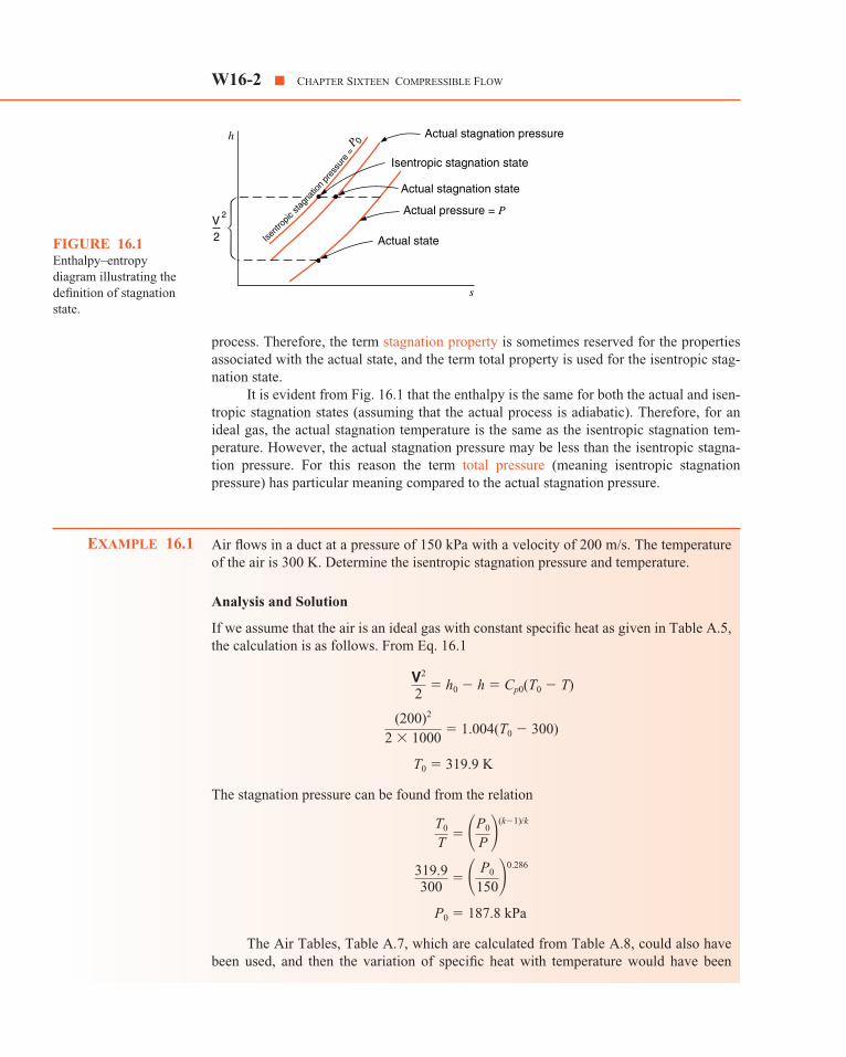
process. Therefore, the term stagnation property is sometimes reserved for the propertiesassociated with the actual state, and the term total property is used for the isentropic stag-nation state.
It is evident from Fig. 16.1 that the enthalpy is the same for both the actual and isen-tropic stagnation states (assuming that the actual process is adiabatic). Therefore, for anideal gas, the actual stagnation temperature is the same as the isentropic stagnation tem-perature. However, the actual stagnation pressure may be less than the isentropic stagna-tion pressure. For this reason the term total pressure (meaning isentropic stagnationpressure) has particular meaning compared to the actual stagnation pressure.
Air flows in a duct at a pressure of 150 kPa with a velocity of 200 m/s. The temperatureof the air is 300 K. Determine the isentropic stagnation pressure and temperature.
Analysis and Solution
If we assume that the air is an ideal gas with constant specific heat as given in Table A.5,the calculation is as follows. From Eq. 16.1
The stagnation pressure can be found from the relation
The Air Tables, Table A.7, which are calculated from Table A.8, could also havebeen used, and then the variation of specific heat with temperature would have been
P0 � 187.8 kPa
319.9300
� � P0
150�0.286
T0
T � �P0
P �(k�1)/k
T0 � 319.9 K
(200)2
2 � 1000 � 1.004(T0 � 300)
V2
2 � h0 � h � Cp0(T0 � T)
EXAMPLE 16.1
W16-2 � CHAPTER SIXTEEN COMPRESSIBLE FLOW
Isent
ropic
stagn
ation
pres
sure
=P 0
Actual stagnation pressure
Isentropic stagnation state
Actual stagnation state
Actual pressure = P
Actual state
s
h
V2
2FIGURE 16.1Enthalpy–entropydiagram illustrating thedefinition of stagnationstate.

taken into account. Since the actual and stagnation states have the same entropy, we pro-ceed as follows: Using Table A.7,
T � 300 K h � 300.47 Pr � 1.1146
h0 � h � � 300.47 � � 320.47
T0 � 319.9 K Pr0 � 1.3956
P0 � 150 � � 187.8 kPa
16.2 THE MOMENTUM EQUATIONFOR A CONTROL VOLUME
Before proceeding, it will be advantageous to develop the momentum equation for thecontrol volume. Newton’s second law states that the sum of the external forces acting on abody in a given direction is proportional to the rate of change of momentum in the givendirection. Writing this in equation form for the x-direction, we have
For the system of units used in this book, the proportionality can be written directlyas an equality.
(16.2)
Equation 16.2 has been written for a body of fixed mass, or in thermodynamic par-lance, for a control mass. We now proceed to write the momentum equation for a controlvolume, and we follow a procedure similar to that used in writing the continuity equationand the first and second laws of thermodynamics for a control volume.
Consider the control volume shown in Fig. 16.2 to be fixed relative to its coordinateframe. Each flow that enters or leaves the control volume possesses an amount of momen-tum per unit mass, so that it adds or subtracts a rate of momentum to or from the controlvolume.
d(mVx)dt
� � Fx
d(mVx)dt
� � Fx
1.39561.1146
(200)2
2 � 1000V2
2
THE MOMENTUM EQUATION FOR A CONTROL VOLUME � W16-3
F
miPi Tivi Vi
·
·d mV
dtPe Teve Ve
me
FIGURE 16.2Development of themomentum equation for acontrol volume.

Writing the momentum equation in a rate form similar to the balance equations formass, energy, and entropy, Eqs. 6.1, 6.7, and 9.2, respectively, results in an expression ofthe form
Rate of change � Fx � in � out (16.3)
Only forces acting on the mass inside the control volume (for example, gravity) or on thecontrol volume surface (for example, friction or piston forces) and the flow of mass carry-ing momentum can contribute to a change of momentum. Momentum is conserved, sothat it cannot be created or destroyed, as was previously stated for the other control vol-ume developments.
The momentum equation in the x-direction from the form of Eq. 16.3 becomes
Fx � Vix � Vex (16.4)
Similarly, for the y- and z- directions,
Fy � Viy � Vey (16.5)
and
Fz � Viz � Vez (16.6)
In the case of a control volume with no mass flow rates in or out (i.e., a controlmass), these equations reduce to the form of Eq. 16.2 for each direction.
In this chapter we will be concerned primarily with steady-state processes in whichthere is a single flow with uniform properties into the control volume, and a single flowwith uniform properties out of the control volume. The steady-state assumption meansthat the rate of momentum change for the control volume terms in Eqs. 16.4, 16.5, and16.6 are equal to zero. That is,
� 0 � 0 � 0 (16.7)
Therefore, for the steady-state process the momentum equation for the control vol-ume, assuming uniform properties at each state, reduces to the form
Fx � (Ve)x � (Vi)x (16.8)
Fy � (Ve)y � (Vi)y (16.9)
Fz � (Ve)z � (Vi)z (16.10)
Furthermore, for the special case in which there is a single flow into and out of the controlvolume, these equations reduce to
Fx � [(Ve)x � (Vi)x] (16.11)
Fy � [(Ve)y � (Vi)y] (16.12)
Fz � [(Ve)z � (Vi)z] (16.13)m�m�m�
� mi� me�� mi� me�� mi� me�
d(mVz)c.v.
dt
d(mVy)c.v.
dtd(mVx)c.v.
dt
� me� mi
d(mVz)dt
� �
� me� mi
d(mVy)
dt � �
� me� mi
d(mVx)dt
� �
�
W16-4 � CHAPTER SIXTEEN COMPRESSIBLE FLOW

On a level floor a man pushing a wheelbarrow (Fig. 16.3) into which sand is falling atthe rate of 1 kg/s. The man is walking at the rate of 1 m/s, and the sand has a velocity of10 m/s as it falls into the wheelbarrow. Determine the force the man must exert on thewheelbarrow and the force the floor exerts on the wheelbarrow due to the falling sand.
Analysis and Solution
Consider a control surface around the wheelbarrow. Consider first the x-direction. FromEq. 16.4
Fx � (Ve)x � (Vi)x
Let us analyze this problem from the point of view of an observer riding on thewheelbarrow. For this observer, Vx of the material in the wheelbarrow is zero and therefore,
However, for this observer the sand crossing the control surface has an x-component ve-locity of �1 m/s, and , the mass flow out of the control volume, is �1 kg/s. Therefore,
Fx � (1 kg/s) � (1 m/s) � 1 N
If one considers this from the point of view of an observer who is stationary on theearth’s surface we conclude that Vx of the falling sand is zero and therefore
(Ve)x � (Vi)x � 0
However, for this observer there is a change of momentum within the control volume,namely,
Next consider the vertical (y) direction.
Fy � (Ve)y � (Vi)y� mi
d(mVy)c.v.
dt � � me�
� Fx � d(mVx)c.v.
dt � (1 m/s) � (1 kg/s) � 1 N
� mi� me
m
d(mVx)c.v.
dt � 0
� mi
d(mVx)c.v.
dt � � me�
EXAMPLE 16.2
THE MOMENTUM EQUATION FOR A CONTROL VOLUME � W16-5
Sand: = 10 m/sm = 1 kg/s
= 1 m/s
Vy
FxVx
–Fy
·
FIGURE 16.3 Sketchfor Example 16.2.

For both the stationary and moving observer, the first term drops out because Vy of themass within the control volume is zero. However, for the mass crossing the control sur-face, Vy � 10 m/s and
� �1 kg/s
Therefore
Fy � (10 m/s) � (�1 kg/s) � �10 N
The minus sign indicates that the force is in the opposite direction to Vy
16.3 FORCES ACTING ON A CONTROL SURFACE
In the last section we considered the momentum equation for the control volume. We nowwish to evaluate the net force on a control surface that causes this change in momentum.Let us do this by considering the control mass shown in Fig. 16.4, which involves a pipebend. The control surface is designated by the dotted lines and is so chosen that at thepoint where the fluid crosses the system boundary, the flow is perpendicular to the controlsurface. The shear forces at the section where the fluid crosses the boundary of the controlsurface are assumed to be negligible. Figure 16.4a shows the velocities, and Fig. 16.4bshows the forces involved. The force R is the result of all external forces on the controlmass, except for the pressure of all surroundings. The pressure of the surroundings, P0,acts on the entire boundary except at Ai and Ae, where the fluid crosses the control surface,Pi and Pe represent the absolute pressures at these points.
m
W16-6 � CHAPTER SIXTEEN COMPRESSIBLE FLOW
P0
ViyVi
Vix
Ve
Vex
Vey
P0
P0
P0
Pi
Pe
Ry
RxR
(a)
(b)
FIGURE 16.4 Forcesacting on a controlsurface.
The net forces acting on the system in the x- and y-directions, Fx and Fy, are the sumof the pressure forces and the external force R in their respective directions. The influenceof the pressure of the surroundings, P0, is most easily taken into account by noting that itacts over the entire control mass boundary except at Ai and Ae. Therefore, we can write
Fx � (PiAi)x � (P0Ai)x � (PeAe)x � (P0Ae)x � Rx
Fy � (PiAi)y � (P0Ai)y � (Pe Ae)y � (P0Ae)y � Ry
This equation may be simplified by combining the pressure terms.
Fx � [(Pi � P0)Ai]x � [(Pe � P0)Ae]x � Rx
Fy � [(Pi � P0)Ai]y � [(Pe � P0)Ae]y � Ry (16.14)
The proper sign for each pressure and force must of course be used in all calculations.Equations 16.8, 16.9, and 16.14 may be combined to give
(16.15)
If there is a single flow across the control surface, Eqs. 16.11, 16.12, and 16.14 can becombined to give
Fx � (Ve � Vi)x � [(Pi � P0)Ai]x � [(Pe � P0)Ae]x � Rx
Fy � (Ve � Vi)y � [(Pi � P0)Ai]y � [(Pe � P0)Ae]y � Ry (16.16)
A similar equation could be written for the z-direction. These equations are very useful inanalyzing the forces involved in a control-volume analysis.
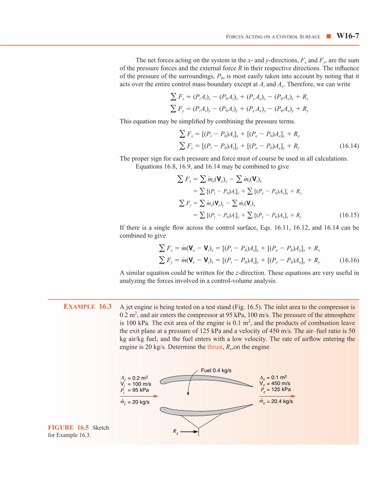
A jet engine is being tested on a test stand (Fig. 16.5). The inlet area to the compressor is0.2 m2, and air enters the compressor at 95 kPa, 100 m/s. The pressure of the atmosphereis 100 kPa. The exit area of the engine is 0.1 m2, and the products of combustion leavethe exit plane at a pressure of 125 kPa and a velocity of 450 m/s. The air–fuel ratio is 50kg air/kg fuel, and the fuel enters with a low velocity. The rate of airflow entering theengine is 20 kg/s. Determine the thrust, Rx,on the engine.
EXAMPLE 16.3
m�m�
� � [(Pi � P0)Ai]y � � [(Pe � P0)Ae]y � Ry
� Fy � � me(Ve)y � � mi˙ (Vi)y
� � [(Pi � P0)Ai]x � � [(Pe � P0)Ae]x � Rx
� Fx � � me(Ve)x � � mi(Vi)x
��
��
FORCES ACTING ON A CONTROL SURFACE � W16-7
Fuel 0.4 kg/s
Rx
= 0.1 m2
= 450 m/s= 125 kPa
= 20.4 kg/s
Ve Pe
me·
Ai Ae= 0.2 m2
= 100 m/s= 95 kPa
= 20 kg/s
ViPi
mi·
FIGURE 16.5 Sketchfor Example 16.3.

Analysis and Solution
In the solution that follows, it is assumed that forces and velocities to the right are positive.Using Eq. 16.16
(Note that the momentum of the fuel entering has been neglected.)
16.4 ADIABATIC, ONE-DIMENSIONAL, STEADY-STATE FLOW OF AN INCOMPRESSIBLEFLUID THROUGH A NOZZLE
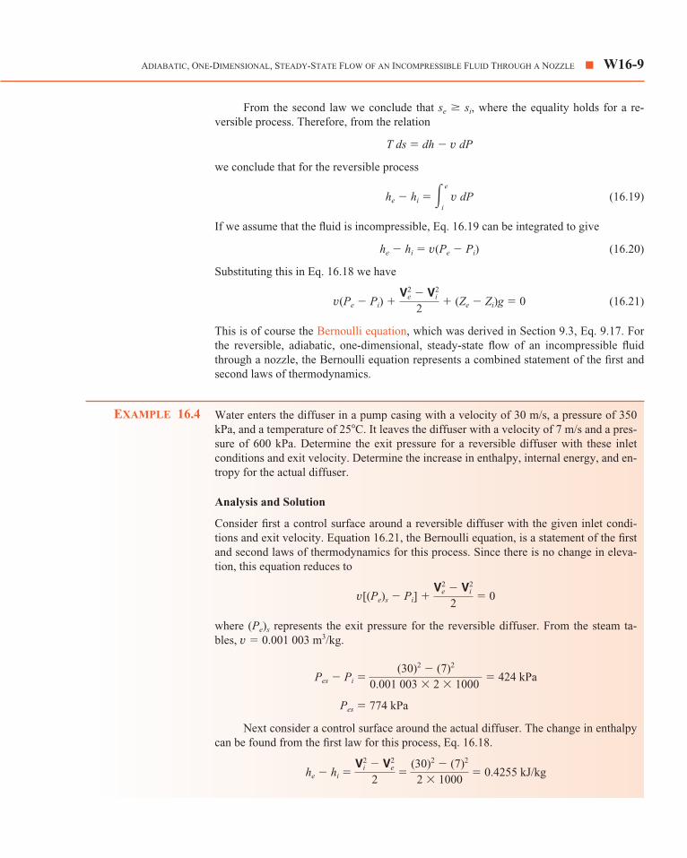
A nozzle is a device in which the kinetic energy of a fluid is increased in an adiabaticprocess. This increase involves a decrease in pressure and is accomplished by the properchange in flow area. A diffuser is a device that has the opposite function, namely, to in-crease the pressure by decelerating the fluid. In this section we discuss both nozzles anddiffusers, but to minimize words we shall use only the term nozzle.
Consider the nozzle shown in Fig. 16.6, and assume an adiabatic, one-dimensional,steady-state process of an incompressible fluid. From the continuity equation we con-clude that
e � mi � �AiVi � �AeVe
or
(16.17)
The first law for this process is
he � hi � � (Ze � Zi)g � 0 (16.18)V2
e � V2i
2
Ai
Ae �
Ve
Vi
m
Rx � 10.68 kN
Rx � [(95 � 100) � 0.2] � [(125 � 100) � 0.1] � 20.4 � 450 � 20 � 1001000
Rx � [(Pi � P0)Ai]x � [(Pe � P0)Ae]x � (meVe � miVi)x
W16-8 � CHAPTER SIXTEEN COMPRESSIBLE FLOW
Control surface
TePeVe
TiPiVi
FIGURE 16.6Schematic sketch of anozzle.
From the second law we conclude that se � si, where the equality holds for a re-versible process. Therefore, from the relation
T ds � dh � v dP
we conclude that for the reversible process
he � hi � (16.19)
If we assume that the fluid is incompressible, Eq. 16.19 can be integrated to give
he � hi � v(Pe � Pi) (16.20)
Substituting this in Eq. 16.18 we have
v(Pe � Pi) � � (Ze � Zi)g � 0 (16.21)
This is of course the Bernoulli equation, which was derived in Section 9.3, Eq. 9.17. Forthe reversible, adiabatic, one-dimensional, steady-state flow of an incompressible fluidthrough a nozzle, the Bernoulli equation represents a combined statement of the first andsecond laws of thermodynamics.
Water enters the diffuser in a pump casing with a velocity of 30 m/s, a pressure of 350kPa, and a temperature of 25�C. It leaves the diffuser with a velocity of 7 m/s and a pres-sure of 600 kPa. Determine the exit pressure for a reversible diffuser with these inletconditions and exit velocity. Determine the increase in enthalpy, internal energy, and en-tropy for the actual diffuser.
Analysis and Solution
Consider first a control surface around a reversible diffuser with the given inlet condi-tions and exit velocity. Equation 16.21, the Bernoulli equation, is a statement of the firstand second laws of thermodynamics for this process. Since there is no change in eleva-tion, this equation reduces to
v[(Pe)s � Pi] � � 0
where (Pe)s represents the exit pressure for the reversible diffuser. From the steam ta-bles, v � 0.001 003 m3/kg.
Next consider a control surface around the actual diffuser. The change in enthalpycan be found from the first law for this process, Eq. 16.18.
he � hi � � 0.4255 kJ/kgV2
i � V2e
2 �
(30)2 � (7)2
2 � 1000
Pes � 774 kPa
Pes � Pi � (30)2 � (7)2
0.001 003 � 2 � 1000 � 424 kPa
V2e � V2
i
2
EXAMPLE 16.4
V2e � V2
i
2
� e
i v dP
ADIABATIC, ONE-DIMENSIONAL, STEADY-STATE FLOW OF AN INCOMPRESSIBLE FLUID THROUGH A NOZZLE � W16-9

The change in internal energy can be found from the definition of enthalpy, he � hi �(ue � ui) � (Peve � Pivi).
Thus, for an incompressible fluid
The change of entropy can be approximated from the familiar relation
T ds � du � P dv
by assuming that the temperature is constant (which is approximately true in this case)and noting that for an incompressible fluid dv � 0. With these assumptions
se � si � � 0.000 586 kJ/kg K
Since this is an irreversible adiabatic process, the entropy will increase, as the above cal-culation indicates.
16.5 VELOCITY OF SOUND IN AN IDEAL GAS
When a pressure disturbance occurs in a compressible fluid, the disturbance travels with avelocity that depends on the state of the fluid. A sound wave is a very small pressure dis-turbance; the velocity of sound, also called the sonic velocity, is an important parameterin compressible-fluid flow. We proceed now to determine an expression for the sonic ve-locity of an ideal gas in terms of the properties of the gas.
Let a disturbance be set up by the movement of the piston at the end of the tube,Fig. 16.7a. A wave travels down the tube with a velocity c, which is the sonic velocity.
ue � ui
T � 0.174 75
298.2
� 0.174 75 kJ/kg
� 0.4255 � 0.001 003(600 � 350)
ue � ui � he � hi � v(Pe � Pi)
W16-10 � CHAPTER SIXTEEN COMPRESSIBLE FLOW
P + dP + dh + dh
dV c
Wave front
P h
Properties of gas after wave passes Properties of gas before wave passes
P h
P + dP + d h + dh
cc – dV
Control surface
(a)
(b)
ρ ρ ρ
ρ ρ ρFIGURE 16.7Diagram illustrating sonicvelocity. (a) Stationaryobserver. (b) Observertraveling with wave front.

Assume that after the wave has passed the properties of the gas have changed an infinites-imal amount and that the gas is moving with the velocity dV toward the wave front.
In Fig. 16.7b this process is shown from the point of view of an observer who trav-els with the wave front. Consider the control surface shown in Fig. 16.7b. From the firstlaw for this steady-state process we can write
(16.22)
From the continuity equation we can write
(16.23)
Consider also the relation between properties
T ds � dh �
If the process is isentropic, ds � 0, and this equation can be combined with Eq. 16.22 togive the relation
� c dV � 0 (16.24)
This can be combined with Eq. 16.23 to give the relation
� c2
Since we have assumed the process to be isentropic, this is better written as a partialderivative.
� c2 (16.25)
An alternate derivation is to introduce the momentum equation. For the control vol-ume of Fig. 16.7b the momentum equation is
(16.26)
On combining this with Eq. 16.23, we obtain Eq. 16.25.
� c2
It will be of particular advantage to solve Eq. 16.25 for the velocity of sound in anideal gas.
When an ideal gas undergoes an isentropic change of state, we found in Chapter 8that, for this process, assuming constant specific heat
or
��P���s
� kP�
dPP
� k d�� � 0
��P���s
dP � �c d V
PA � (P � dP)A � m(c � d V � c) � �Ac(c �d V � c)
��P���s
dPd�
dP�
dP�
c d� � � dV � 0
��c � (� � d�)�(c � dV)
dh � c d V � 0
h � c2
2 � (h � dh) �
(c � d V)2
2
VELOCITY OF SOUND IN AN IDEAL GAS � W16-11

Substituting this equation in Eq. 16.25, we have an equation for the velocity ofsound in an ideal gas,
c2 � (16.27)
Since for an ideal gas
this equation may also be written
c2 � kRT (16.28)
Determine the velocity of sound in air at 300 K and at 1000 K.
Analysis and Solution
Using Eq. 16.28
Similarly, at 1000 K, using k � 1.4,
c � � 633.9 m/s
Note the significant increase in sonic velocity as the temperature increases.
The Mach number, M, is defined as the ratio of the actual velocity V to the sonicvelocity c.
M � (16.29)
When M � 1 the flow is supersonic; when M � 1 the flow is subsonic; and when M � 1the flow is sonic. The importance of the Mach number as a parameter in fluid-flow prob-lems will be evident in the paragraphs that follow.
16.6 REVERSIBLE, ADIABATIC, ONE-DIMENSIONAL FLOW OF ANIDEAL GAS THROUGH A NOZZLE
A nozzle or diffuser with both a converging and diverging section is shown in Fig. 16.8.The minimum cross-sectional area is called the throat.
Our first consideration concerns the conditions that determine whether a nozzle ordiffuser should be converging or diverging, and the conditions that prevail at the throat.For the control volume shown, the following relations can be written.
Vc
�1.4 � 0.287 � 1000 � 1000
� �1.4 � 0.287 � 300 � 1000 � 347.2 m/s
c � �kRT
EXAMPLE 16.5
P� � RT
kP�
W16-12 � CHAPTER SIXTEEN COMPRESSIBLE FLOW
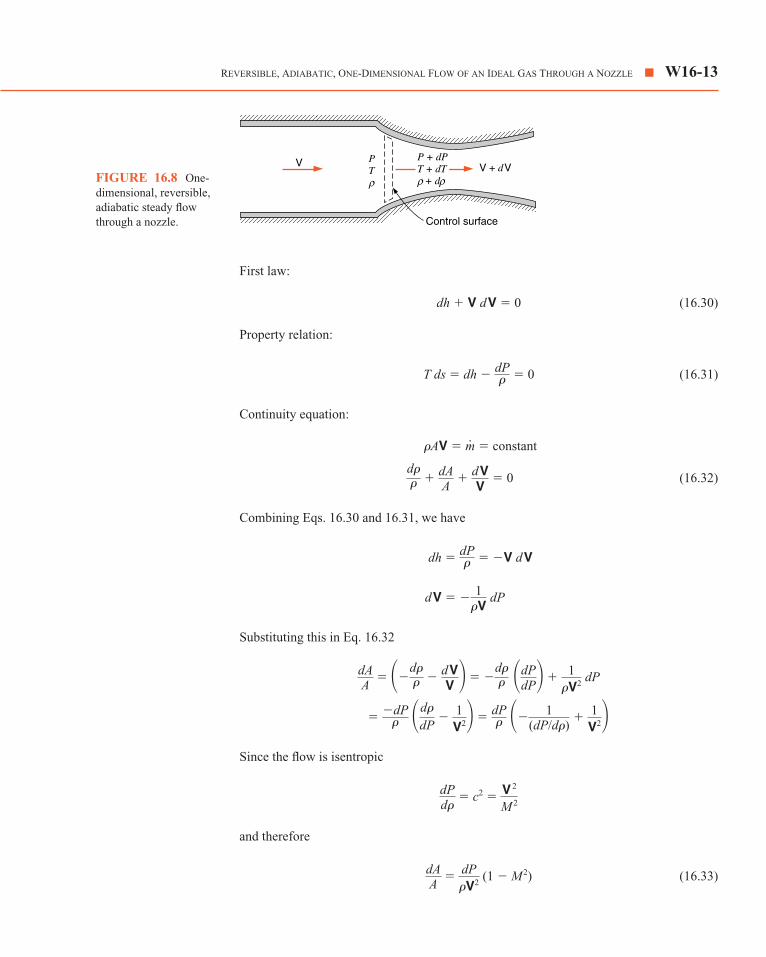
First law:
dh � V dV � 0 (16.30)
Property relation:
T ds � dh � � 0 (16.31)
Continuity equation:
(16.32)
Combining Eqs. 16.30 and 16.31, we have
Substituting this in Eq. 16.32
Since the flow is isentropic
and therefore
(1 � M2) (16.33)dAA
� dP�V2
dPd�
� c2 � V
2
M
2
� �dP� �d�
dP � 1
V2� � dP� ��
1(dP/d�)
� 1V2�
dAA
� ��d�� � d V
V � � �d�� �dP
dP� � 1�V2
dP
d V � � 1�V
dP
dh � dP� � �V d V
d�� � dA
A � d V
V � 0
�AV � m � constant
dP�
REVERSIBLE, ADIABATIC, ONE-DIMENSIONAL FLOW OF AN IDEAL GAS THROUGH A NOZZLE � W16-13
V + dVV
Control surface
PT
P + dPT + dT + dρ ρ ρFIGURE 16.8 One-
dimensional, reversible,adiabatic steady flowthrough a nozzle.

This is a very significant equation, for from it we can draw the following conclusionsabout the proper shape for nozzles and diffusers:
For a nozzle, dP � 0. Therefore,
for a subsonic nozzle, M � 1 ⇒ dA � 0, and the nozzle is converging;
for a supersonic nozzle, M � 1 ⇒ dA � 0, and the nozzle is diverging.
For a diffuser, dP � 0. Therefore,
for a subsonic diffuser, M � 1 ⇒ dA � 0, and the diffuser is diverging;
for a supersonic diffuser, M � 1 ⇒ dA � 0, and the diffuser is converging.
When M � 1, dA � 0, which means that sonic velocity can be achieved only at thethroat of a nozzle or diffuser. These conclusions are summarized in Fig. 16.9.
We will now develop a number of relations between the actual properties, stagna-tion properties, and Mach number. These relations are very useful in dealing with isen-tropic flow of an ideal gas in a nozzle.
Equation 16.1 gives the relation between enthalpy, stagnation enthalpy, and kineticenergy.
h � � h0
For an ideal gas with constant specific heat, Eq. 16.1 can be written as
V2 � 2Cp0(T0 � T) � 2 kRTk � 1
�T0
T � 1�
V2
2
W16-14 � CHAPTER SIXTEEN COMPRESSIBLE FLOW
M > 1Supersonic
P DecreasesA Increases
M > 1Supersonic
P IncreasesA Decreases
M < 1Subsonic
P DecreasesA Decreases
M < 1Subsonic
P IncreasesA Increases
(a)
(b)
FIGURE 16.9Required area changes for(a) nozzles and (b) diffusers.
Since
(16.34)
For an isentropic process,
Therefore,
(16.35)
(16.36)
Values of P/P0, �/�0, and T/T0 are given as a function of M in Table A.12 for thevalue k � 1.40.
The conditions at the throat of the nozzle can be found by noting that M � 1 at thethroat. The properties at the throat are denoted by an asterisk (*). Therefore,
(16.37)
(16.38)
(16.39)
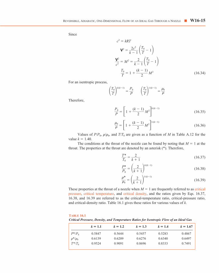
These properties at the throat of a nozzle when M � 1 are frequently referred to as criticalpressure, critical temperature, and critical density, and the ratios given by Eqs. 16.37,16.38, and 16.39 are referred to as the critical-temperature ratio, critical-pressure ratio,and critical-density ratio. Table 16.1 gives these ratios for various values of k.
�*�0
� � 2k � 1�
1/(k�1)
P*P0
� � 2k � 1�
k/(k�1)
T *T0
� 2k � 1
�0
� � �1 � (k � 1)
2 M
2�1/(k�1)
P0
P � �1 �
(k � 1)2
M
2�k/(k�1)
�T0
T �1/(k�1)
� �0
��T0
T �k/(k�1)
� P0
P
T0
T � 1 �
(k � 1)2
M
2
V2
c2 � M
2 � 2k � 1
�T0
T � 1�
V2 � 2c2
k � 1 �T0
T � 1�
c2 � kRT
REVERSIBLE, ADIABATIC, ONE-DIMENSIONAL FLOW OF AN IDEAL GAS THROUGH A NOZZLE � W16-15
k � 1.1 k � 1.2 k � 1.3 k � 1.4 k � 1.67
P*/P0 0.5847 0.5644 0.5457 0.5283 0.4867
�*/�0 0.6139 0.6209 0.6276 0.6340 0.6497
T*/T0 0.9524 0.9091 0.8696 0.8333 0.7491
TABLE 16.1Critical Pressure, Density, and Temperature Ratios for Isentropic Flow of an Ideal Gas

16.7 MASS RATE OF FLOW OF AN IDEAL GASTHROUGH AN ISENTROPIC NOZZLE
We now turn our attention to a consideration of the mass rate of flow per unit area, /A, ina nozzle. From the continuity equation we proceed as follows:
(16.40)
By substituting Eq. 16.35 into Eq. 16.40, the flow per unit area can be expressed in termsof stagnation pressure, stagnation temperature, Mach number, and gas properties.
(16.41)
At the throat, M � 1, and therefore the flow per unit area at the throat, /A*, can be foundby setting M � 1 in Eq. 16.41.
(16.42)
The area ratio A/A* can be obtained by dividing Eq. 16.42 by Eq. 16.41.
(16.43)
The area ratio A/A* is the ratio of the area at the point where the Mach number is M to thethroat area, and values of A/A* as a function of Mach number are given in Table A.12 onpage W16-35. Figure 16.10 shows a plot of A/A* vs. M, which is in accordance with our pre-vious conclusion that a subsonic nozzle is converging and a supersonic nozzle is diverging.
AA*
� 1M
�� 2k � 1��1 � k �1
2 M
2��(k�1)/ 2(k�1)
mA*
� P0
�T0k
R �
1
�k � 12 �(k�1)/2(k�1)
m
mA
� P0
�T0
kR
� M
�1 � k � 12
M
2�(k�1)/ 2(k�1)
� PM
�T0
kR
1 � k � 12
M
2
� PV�kRT k
R T0
T 1
T0
mA
� �V � PVRT
kT0
kT0
m
W16-16 � CHAPTER SIXTEEN COMPRESSIBLE FLOW
k = 1.4
AA4
3
2
1
0.5 1.0 1.5 2.0 2.5 3.0
*
M
FIGURE 16.10 Arearatio as a function ofMach number for areversible, adiabaticnozzle.
The final point to be made regarding the isentropic flow of an ideal gas through anozzle involves the effect of varying the back pressure (the pressure outside the nozzleexit) on the mass rate of flow.
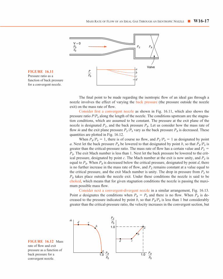
Consider first a convergent nozzle as shown in Fig. 16.11, which also shows thepressure ratio P/P0 along the length of the nozzle. The conditions upstream are the stagna-tion conditions, which are assumed to be constant. The pressure at the exit plane of thenozzle is designated PE, and the back pressure PB. Let us consider how the mass rate offlow and the exit plane pressure PE /P0 vary as the back pressure PB is decreased. Thesequantities are plotted in Fig. 16.12.
When PB /P0 � 1, there is of course no flow, and PE /P0 � 1 as designated by pointa. Next let the back pressure PB be lowered to that designated by point b, so that PB /P0 isgreater than the critical-pressure ratio. The mass rate of flow has a certain value and PE �PB. The exit Mach number is less than 1. Next let the back pressure be lowered to the crit-ical pressure, designated by point c. The Mach number at the exit is now unity, and PE isequal to PB. When PB is decreased below the critical pressure, designated by point d, thereis no further increase in the mass rate of flow, and PE remains constant at a value equal tothe critical pressure, and the exit Mach number is unity. The drop in pressure from PE toPB takes place outside the nozzle exit. Under these conditions the nozzle is said to bechoked, which means that for given stagnation conditions the nozzle is passing the maxi-mum possible mass flow.
Consider next a convergent-divergent nozzle in a similar arrangement, Fig. 16.13.Point a designates the conditions when PB � P0 and there is no flow. When PB is de-creased to the pressure indicated by point b, so that PB/P0 is less than 1 but considerablygreater than the critical-pressure ratio, the velocity increases in the convergent section, but
m
MASS RATE OF FLOW OF AN IDEAL GAS THROUGH AN ISENTROPIC NOZZLE � W16-17
abcd
P0
V ≈ 0
T0
PE PB
P––P0
Valve
FIGURE 16.11Pressure ratio as afunction of back pressurefor a convergent nozzle.
m· d cb
a1.0
a
b
cd
1.0
1.0PB––P0
PB––P0
PE––P0
FIGURE 16.12 Massrate of flow and exitpressure as a function ofback pressure for aconvergent nozzle.

M � 1 at the throat. Therefore, the diverging section acts as a subsonic diffuser in whichthe pressure increases and velocity decreases. Point c designates the back pressure atwhich M � 1 at the throat, but the diverging section acts as a subsonic diffuser (with M � 1at the inlet) in which the pressure increases and velocity decreases. Point d designates oneother back pressure that permits isentropic flow, and in this case the diverging section actsas a supersonic nozzle, with a decrease in pressure and an increase in velocity. Betweenthe back pressures designated by points c and d, an isentropic solution is not possible, andshock waves will be present. This matter is discussed in the section that follows. Whenthe back pressure is decreased below that designated by point d, the exit-plane pressure PE
remains constant, and the drop in pressure from PE to PB takes place outside the nozzle.This is designated by point e.
A convergent nozzle has an exit area of 500 mm2. Air enters the nozzle with a stagnationpressure of 1000 kPa and a stagnation temperature of 360 K. Determine the mass rate offlow for back pressures of 800 kPa, 528 kPa, and 300 kPa, assuming isentropic flow.
Analysis and Solution
For air k � 1.4 and Table A.12 may be used. The critical-pressure ratio, P*/P0 is 0.528.Therefore, for a back pressure of 528 kPa, M � 1 at the nozzle exit and the nozzle ischoked. Decreasing the back pressure below 528 kPa will not increase the flow.
For a back pressure of 528 kPa,
� 0.8333 T* � 300 K
At the exit
m � �AV
�* � P*RT *
� 5280.287 � 300
� 6.1324 kg/m3
� �1.4 � 0.287 � 300 � 1000 � 347.2 m/s
V � c � �kRT
T *T0
EXAMPLE 16.6
W16-18 � CHAPTER SIXTEEN COMPRESSIBLE FLOW
P0
V ≈ 0
T0
Throat 1.0
PE PB
abc
de
P––P0
FIGURE 16.13Nozzle pressure ratio as afunction of back pressurefor a reversible,convergent-divergentnozzle.

Applying this relation to the throat section
� 6.1324 � 500 � 10�6 � 347.2 � 1.0646 kg/s
For a back pressure of 800 kPa, PE/P0 � 0.8 (subscript E designates the propertiesin the exit plane). From Table A.12
Applying this relation to the exit section,
� 8.2542 � 500 � 10�6 � 211.1 � 0.8712 kg/s
For a back pressure less than the critical pressure, which in this case is 528 kPa,the nozzle is choked and the mass rate of flow is the same as that for the critical pres-sure. Therefore, for an exhaust pressure of 300 kPa, the mass rate of flow is 1.0646 kg/s.
A converging-diverging nozzle has an exit area to throat area ratio of 2. Air enters thisnozzle with a stagnation pressure of 1000 kPa and a stagnation temperature of 360 K.The throat area is 500 mm2. Determine the mass rate of flow, exit pressure, exit tempera-ture, exit Mach number, and exit velocity for the following conditions:
a. Sonic velocity at the throat, diverging section acting as a nozzle.(Corresponds to point d in Fig. 16.13.)
b. Sonic velocity at the throat, diverging section acting as a diffuser.(Corresponds to point c in Fig. 16.13.)
Analysis and Solution
(a) In Table A.12 of the Appendix we find that there are two Mach number listed forA/A* � 2. One of these is greater than unity and one is less than unity. When the diverg-ing section acts as a supersonic nozzle, we use the value for M � 1. The following arefrom Table A.12
� 2.0 ME � 2.197 � 0.0939 � 0.5089TE
T0
PE
P0
AE
A*
EXAMPLE 16.7
m
m � �AV
�E � PE
RTE � 800
0.287 � 337.7 � 8.2542 kg/m3
VE � ME
cE � 211.1 m/s
cE � �kRTE � �1.4 � 0.287 � 337.7 � 1000 � 368.4 m/s
TE � 337.7 K
ME � 0.573 � � TE/T0 � 0.9381
m
MASS RATE OF FLOW OF AN IDEAL GAS THROUGH AN ISENTROPIC NOZZLE � W16-19

Therefore,
PE � 0.0939(1000) � 93.9 kPa
TE � 0.5089(360) � 183.2 K
cE � � 271.3 m/s
VE � MEcE � 2.197(271.3) � 596.1 m/s
The mass rate of flow can be determined by considering either the throat section orthe exit section. However, in general it is preferable to determine the mass rate of flowfrom conditions at the throat. Since in this case M � 1 at the throat, the calculation isidentical to the calculation for the flow in the convergent nozzle of Example 16.6 whenit is choked.
(b) The following are from Table A.12.
� 2.0 M � 0.308 � 0.936 � 0.9812
PE � 0.936(1000) � 936 kPa
TE � 0.9812(360) � 353.3 K
cE � � 376.8 m/s
VE � MEcE � 0.308(376.8) � 116 m/s
Since M � 1 at the throat, the mass rate of flow is the same as in (a), which is alsoequal to the flow in the convergent nozzle of Example 16.6 when it is choked.
In the example above, a solution assuming isentropic flow is not possible if the backpressure is between 936 kPa and 93.9 kPa. If the back pressure is in this range, there willbe either a normal shock in the nozzle or oblique shock waves outside the nozzle. Thematter of normal shock waves is considered in the following section.
16.8 NORMAL SHOCK IN AN IDEAL GASFLOWING THROUGH A NOZZLE
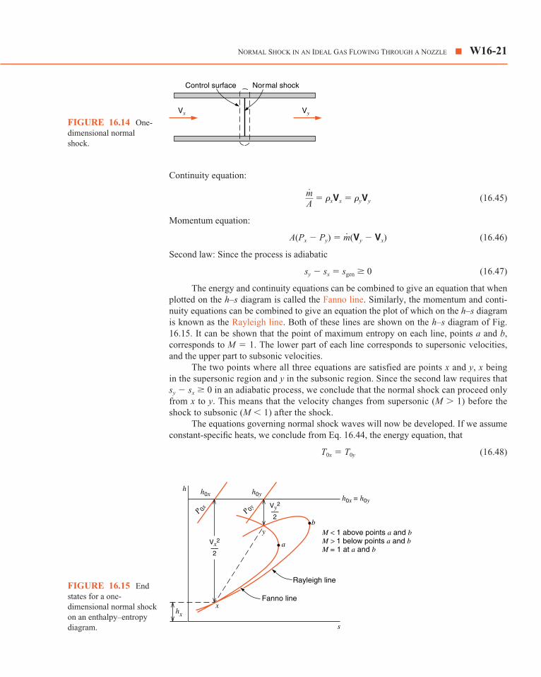
A shock wave involves an extremely rapid and abrupt change of state. In a normal shockthis change of state takes place across a plane normal to the direction of the flow. Figure16.14 shows a control surface that includes such a normal shock. We can now determinethe relations that govern the flow. Assuming steady-state, steady-flow, we can write thefollowing relations, where subscripts x and y denote the conditions upstream and down-stream of the shock, respectively. Note that no heat or work crosses the control surface.
First law:
hx � � hy � � h0x � h0y (16.44)V2
y
2V2
x
2
�kRTE � �1.4 � 0.287 � 353.3 � 1000
TE
T0
PE
P0
AE
A*
�kRTE � �1.4 � 0.287 � 183.2 � 1000
W16-20 � CHAPTER SIXTEEN COMPRESSIBLE FLOW
Continuity equation:
� �xVx � �yVy (16.45)
Momentum equation:
A(Px � Py) � (Vy � Vx) (16.46)
Second law: Since the process is adiabatic
sy � sx � sgen � 0 (16.47)
The energy and continuity equations can be combined to give an equation that whenplotted on the h–s diagram is called the Fanno line. Similarly, the momentum and conti-nuity equations can be combined to give an equation the plot of which on the h–s diagramis known as the Rayleigh line. Both of these lines are shown on the h–s diagram of Fig.16.15. It can be shown that the point of maximum entropy on each line, points a and b,corresponds to M � 1. The lower part of each line corresponds to supersonic velocities,and the upper part to subsonic velocities.
The two points where all three equations are satisfied are points x and y, x beingin the supersonic region and y in the subsonic region. Since the second law requires thatsy � sx � 0 in an adiabatic process, we conclude that the normal shock can proceed onlyfrom x to y. This means that the velocity changes from supersonic (M � 1) before theshock to subsonic (M � 1) after the shock.
The equations governing normal shock waves will now be developed. If we assumeconstant-specific heats, we conclude from Eq. 16.44, the energy equation, that
T0x � T0y (16.48)
m
mA
NORMAL SHOCK IN AN IDEAL GAS FLOWING THROUGH A NOZZLE � W16-21
Vx
Normal shockControl surface
Vy
FIGURE 16.14 One-dimensional normalshock.
Rayleigh line
Fanno line
s
h h0x h0yh0x = h0y
P 0x P 0y
a
b
Vy2
––2
Vx2
––2
xhx
y M < 1 above points a and bM > 1 below points a and bM = 1 at a and b
FIGURE 16.15 Endstates for a one-dimensional normal shockon an enthalpy–entropydiagram.

That is, there is no change in stagnation temperature across a normal shock. IntroducingEq. 16.34
� 1 � � 1 �
and substituting into Eq. 16.48 we have
(16.49)
The equation of state, the definition of Mach number, and the relation c �can be introduced into the continuity equation as follows:
�xVx � �yVy
But
�x � �y �
(16.50)
Combining Eqs. 16.49 and 16.50, which involves combining the energy equations and thecontinuity equation, gives the equation of the Fanno line.
(16.51)
The momentum and continuity equations can be combined as follows to give theequation of the Rayleigh line.
(16.52) Py
Px �
1 � kM
2x
1 � kM
2y
Px(1 � kM
2x) � Py(1 � kM
2y)
Px � PxM
2x
RTx (kRTx) � Py �
PyM
2y
RTy (kRTy)
Px � �xM
2xc
2x � Py � �y
M
2yc
2y
Px � �xV2x � Py � �yV
2y
Px � Py � mA
(Vy � Vx) � �yV2y � �xV
2x
Py
Px �
Mx 1 � k � 12
M
2x
My 1 � k � 12
M
2y
� �Py
Px�2�My
Mx�2
Ty
Tx �
PyVy
PxVx �
Py
My
cy
Px
Mx
cx �
Py
My�Ty
Px
Mx�Tx
Py
RTy
Px
RTx
�kRT
Ty
Tx �
1 � k � 12
M
2x
1 � k � 12
M
2y
k � 12
M
2y
T0y
Ty
k � 12
M
2x
T0x
Tx
W16-22 � CHAPTER SIXTEEN COMPRESSIBLE FLOW
Equations 16.51 and 16.52 can be combined to give the following equation relating Mx
and My.
(16.53)
Table A.13, on page W16-36, gives the normal shock functions, which include My
as a function of Mx. This table applies to an ideal gas with a value k � 1.40. Note that Mx
is always supersonic and My is always subsonic, which agrees with the previous statementthat in a normal shock the velocity changes from supersonic to subsonic. These tables alsogive the pressure, density, temperature, and stagnation pressure ratios across a normalshock as a function of Mx. These are found from Eqs. 16.49 and 16.50 and the equation ofstate. Note that there is always a drop in stagnation pressure across a normal shock and anincrease in the static pressure.
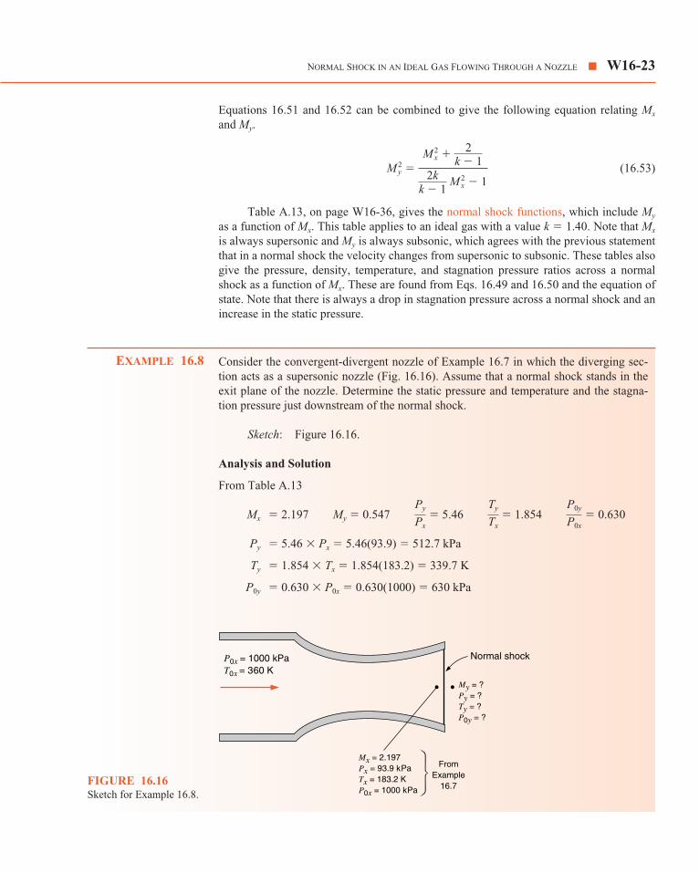
Consider the convergent-divergent nozzle of Example 16.7 in which the diverging sec-tion acts as a supersonic nozzle (Fig. 16.16). Assume that a normal shock stands in theexit plane of the nozzle. Determine the static pressure and temperature and the stagna-tion pressure just downstream of the normal shock.
Sketch: Figure 16.16.
Analysis and Solution
From Table A.13
Mx � 2.197 My � 0.547 � 5.46 � 1.854 � 0.630
Py � 5.46 � Px � 5.46(93.9) � 512.7 kPa
Ty � 1.854 � Tx � 1.854(183.2) � 339.7 K
P0y � 0.630 � P0x � 0.630(1000) � 630 kPa
P0y
P0x
Ty
Tx
Py
Px
EXAMPLE 16.8
M
2y �
M
2x � 2
k � 12k
k � 1 M
2x � 1
NORMAL SHOCK IN AN IDEAL GAS FLOWING THROUGH A NOZZLE � W16-23
P0x = 1000 kPaT0x = 360 K
Normal shock
Mx = 2.197Px = 93.9 kPaTx = 183.2 KP0x = 1000 kPa
FromExample
16.7
My = ?Py = ?Ty = ?P0y = ?
FIGURE 16.16Sketch for Example 16.8.

In the light of this example, we can conclude the discussion concerning the flowthrough a convergent-divergent nozzle. Figure 16.13 is repeated here as Fig. 16.17 forconvenience, except that points f, g, and h have been added. Consider point d. We have al-ready noted that with this back pressure the exit plane pressure PE is just equal to the backpressure PB, and isentropic flow is maintained in the nozzle. Let the back pressure beraised to that designated by point f. The exit-plane pressure PE is not influenced by this in-crease in back pressure, and the increase in pressure from PE to PB takes place outside thenozzle. Let the back pressure be raised to that designated by point g, which is just suffi-cient to cause a normal shock to stand in the exit plane of the nozzle. The exit-plane pres-sure PE (downstream of the shock) is equal to the back pressure PB, and M � 1 leaving thenozzle. This is the case in Example 16.8. Now let the back pressure be raised to that corre-sponding to point h. As the back pressure is raised from g to h the normal shock movesinto the nozzle as indicated. Since M � 1 downstream of the normal shock, the divergingpart of the nozzle that is downstream of the shock acts as a subsonic diffuser. As the backpressure is increased from h to c the shock moves further upstream and disappears at thenozzle throat where the back pressure corresponds to c. This is reasonable since there areno supersonic velocities involved when the back pressure corresponds to c, and hence noshock waves are possible.
Consider the convergent-divergent nozzle of Examples 16.7 and 16.8. Assume that thereis a normal shock wave standing at the point where M � 1.5. Determine the exit-planepressure, temperature, and Mach number. Assume isentropic flow except for the normalshock (Fig. 16.18).
Sketch: Figure 16.18.
Analysis and Solution
The properties at point x can be determined from Table A.12, because the flow is isen-tropic to point x.
Mx � 1.5 � 0.2724 � 0.6897 � 1.1762Ax
A*x
Tx
T0x
Px
P0x
EXAMPLE 16.9
W16-24 � CHAPTER SIXTEEN COMPRESSIBLE FLOW
1.0
PE PB
abc
de
P––P0
hgf
FIGURE 16.17Nozzle pressure ratio as a function of backpressure for a convergent–divergent nozzle.

Therefore,
Px � 0.2724(1000) � 272.4 kPa
Tx � 0.6897(360) � 248.3 K
The properties at point y can be determined from the normal shock functions,Table A.13.
My � 0.7011 � 2.4583 � 1.320 � 0.9298
Py � 2.4583Px � 2.4583(272.4) � 669.6 kPa
Ty � 1.320Tx � 1.320(248.3) � 327.8 K
P0y � 0.9298P0x � 0.9298(1000) � 929.8 kPa
Since there is no change in stagnation temperature across a normal shock,
T0x � T0y � 360 K
From y to E the diverging section acts as a subsonic diffuser. In solving thisproblem, it is convenient to think of the flow at y as having come from an isentropicnozzle having a throat area Such a hypothetical nozzle is shown by the dottedline. From the table of isentropic flow functions, Table A.12, we find the followingfor My � 0.7011.
My � 0.7011 � 1.0938 � 0.7202 � 0.9105
From the statement of the problem
� 2.0
Also, since the flow from y to E is isentropic,
� � 2.0 � � 1 � 1.0938 � 1.86011.1762
AE
A*y
AE
A*E �
AE
A*y �
AE
A*x �
A*xAx
� Ax
Ay �
Ay
A*y
AE
A*x
Ty
T0y
Py
P0y
Ay
A*y
A*y .
P0y
P0x
Ty
Tx
Py
Px
NORMAL SHOCK IN AN IDEAL GAS FLOWING THROUGH A NOZZLE � W16-25
PE = ?ME = ?
x y
P0 = 1000 kPaT0 = 360 K
Mx = 1.5 Mv = ?
A Ax* y*
FIGURE 16.18Sketch for Example 16.9.

From the table of isentropic flow functions for A/A* � 1.860 and M � 1
ME � 0.339 � 0.9222 � 0.9771
� 0.9222
PE � 0.9222(P0y) � 0.9222(929.8) � 857.5 kPa
TE � 0.9771(T0E) � 0.9771(360) � 351.7 K
In considering the normal shock, we have ignored the effect of viscosity and thermalconductivity, which are certain to be present. The actual shock wave will occur over somefinite thickness. However, the development as given here gives a very good qualitativepicture of normal shocks, and also provides a basis for fairly accurate quantitative results.
16.9 NOZZLE AND DIFFUSER COEFFICIENTS
Up to this point we have considered only isentropic flow and normal shocks. As waspointed out in Chapter 9, isentropic flow through a nozzle provides a standard to whichthe performance of an actual nozzle can be compared. For nozzles, the three important pa-rameters by which actual flow can be compared to the ideal flow are nozzle efficiency, ve-locity coefficient, and discharge coefficient. These are defined as follows:
The nozzle efficiency �N is defined as
�N � (16.54)
The efficiency can be defined in terms of properties. On the h–s diagram of Fig.16.19 state 0i represents the stagnation state of the fluid entering the nozzle; state e repre-sents the actual state at the nozzle exit; and state s represents the state that would havebeen achieved at the nozzle exit if the flow had been reversible and adiabatic to the sameexit pressure. Therefore, in terms of these states the nozzle efficiency is
�N �h0i � he
h0i � hs
Actual kinetic energy at nozzle exitKinetic energy at nozzle exit with isentropic flow to same exit pressure
PE
P0E �
PE
P0y
TE
T0E
PE
P0E
W16-26 � CHAPTER SIXTEEN COMPRESSIBLE FLOW
h
s
P0
PEhs
he
h0i
Ve2
2
FIGURE 16.19Enthalpy–entropydiagram showing theeffects of irreversibility ina nozzle.

Nozzle efficiencies vary in general from 90 to 99%. Large nozzles usually havehigher efficiencies than small nozzles, and nozzles with straight axes have higher efficien-cies than nozzles with curved axes. The irreversibilities, which cause the departure fromisentropic flow, are primarily due to fricitional effects and are confined largely to theboundary layer. The rate of change of cross-sectional area along the nozzle axis (that is,the nozzle contour) is an important parameter in the design of an efficient nozzle, particu-larly in the divergent section. Detailed consideration of this matter is beyond the scope ofthis text, and the reader is referred to standard references on the subject.
The velocity coefficient CV is defined as
CV � (16.55)
It follows that the velocity coefficient is equal to the square root of the nozzle efficiency
CV � (16.56)
The coefficient of discharge CD is defined by the relation
CD �
In determining the mass rate of flow with isentropic conditions, the actual back pres-sure is used if the nozzle is not choked. If the nozzle is choked, the isentropic mass rate offlow is based on isentropic flow and sonic velocity at the minimum section (that is, sonic ve-locity at the exit of a convergent nozzle and at the throat of a convergent–divergent nozzle).
The performance of a diffuser is usually given in terms of diffuser efficiency, whichis best defined with the aid of an h–s diagram. On the h–s diagram of Fig. 16.20 states 1and 01 are the actual and stagnation state of the fluid entering the diffuser. States 2 and 02are the actual and stagnation states of the fluid leaving the diffuser. State 3 is not attainedin the diffuser, but it is the state that has the same entropy as the initial state and the pres-sure of the isentropic stagnation state leaving the diffuser. The efficiency of the diffuser�D is defined as
�D � (16.57)�hs
V21/2
� h3 � h1
h01 � h1 �
h3 � h1
h02 � h1
Actual mass rate of flowMass rate of flow with isentropic flow
��N
Actual velocity at nozzle exitVelocity at nozzle exit with isentropic flow and same exit pressure
NOZZLE AND DIFFUSER COEFFICIENTS � W16-27
h
s
∆hsP1
P01P02
P2
V12
2
01 02
32
1
FIGURE 16.20Enthalpy–entropydiagram showing thedefinition of diffuserefficiency.

If we assume an ideal gas with constant specific heat this reduces to
�D �
Cp0 � T1 �
Therefore,
(16.58)
16.10 NOZZLES AND ORIFICESAS FLOW-MEASURING DEVICES
The mass rate of flow of a fluid flowing in a pipe is frequently determined by measuringthe pressure drop across a nozzle or orifice in the line, as shown in Fig. 16.21. The idealprocess for such a nozzle or orifice is assumed to be isentropic flow through a nozzle that
�D � �1 � k � 1
2 M
21��P02
P01�(k�1)/k
� 1
k � 12
M
21
�P02
P1�(k�1)/k
� �1 � k � 12
M
21��P02
P01�(k�1)/k
�P02
P1�(k�1)/k
� �P01
P1�(k�1)/k
� �P02
P01�(k�1)/k
�D � �P02
P1�(k�1)/k
� 1
k � 12
M
21
T3
T1 � �P02
P1�(k�1)/k
V21 � M
21c
21
c21
kRkR
k � 1
T3 � T1
T02 � T1 �
(T3 � T1)T1
T1
V21
2 Cp0
W16-28 � CHAPTER SIXTEEN COMPRESSIBLE FLOW
(b)(a)
Well-rounded orifice
Venacontracta
Sharp-edged orifice
FIGURE 16.21Nozzles and orifices asflow-measuring devices.
has the measured pressure drop from inlet to exit and a minimum cross-sectional areaequal to the minimum area of the nozzle or orifice. The actual flow is related to the idealflow by the coefficient of discharge, which is defined by Eq. 16.57.
The pressure difference measured across an orifice depends on the location of thepressure taps as indicated in Fig. 16.21. Since the ideal flow is based on the measuredpressure difference, it follows that the coefficient of discharge depends on the locations ofthe pressure taps. Also, the coefficient of discharge for a sharp-edged orifice is consider-ably less than that for a well-rounded nozzle, primarily due to a contraction of the stream,known as the vena contracta, as it flows through a sharp-edged orifice.
There are two approaches to determining the discharge coefficient of a nozzle ororifice. One is to follow a standard design procedure, such as the ones established by theAmerican Society of Mechanical Engineers,1 and use the coefficient of discharge givenfor a particular design. A more accurate method is to calibrate a given nozzle or orifice,and determine the discharge coefficient for a given installation by accurately measuringthe actual mass rate of flow. The procedure to be followed will depend on the accuracydesired and other factors involved (such as time, expense, availability of calibration facili-ties) in a given situation.
For incompressible fluids flowing through an orifice, the ideal flow for a given pres-sure drop can be found by the procedure outlined in Section 16.4. Actually, it is advanta-geous to combine Eqs. 16.17 and 16.21 to give the following relation, which is valid forreversible flow.
v(P2 � P1) � � v(P2 � P1) � � 0 (16.59)
or
v(P2 � P1) � � 0
V2 � (16.60)
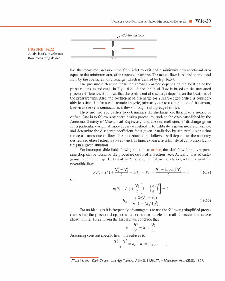
For an ideal gas it is frequently advantageous to use the following simplified proce-dure when the pressure drop across an orifice or nozzle is small. Consider the nozzleshown in Fig. 16.22. From the first law we conclude that
hi � � he �
Assuming constant specific heat, this reduces to
� hi � he � Cp0(Ti � Te)V2
e � V2i
2
V2e
2V2
i
2
2v(P1 � P2)
[1 � (A2/A1)2]
V22
2 �1 � �A2
A1�2�
V22 � (A2
/A1)2V2
2
2V2
2 � V21
2
NOZZLES AND ORIFICES AS FLOW-MEASURING DEVICES � W16-29
1Fluid Meters, Their Theory and Application, ASME, 1959; Flow Measurement, ASME, 1959.
Control surface
FIGURE 16.22Analysis of a nozzle as aflow-measuring device.

Let �P and �T be the decrease in pressure and temperature across the nozzle. Since weare considering reversible adiabatic flow, we note that
or
Using the binomial expansion on the right side of the equation, we have
1 � � 1 � � � �
If �P/Pi is small, this reduces to
Substituting this into the first-law equation, we have
� Cp0
But for an ideal gas
Cp0 � and vi � R
Therefore,
� vi �P
which is the same as Eq. 16.59, which was developed for incompressible flow. Therefore,when the pressure drop across a nozzle or orifice is small, the flow can be calculated withhigh accuracy by assuming incompressible flow.
The Pitot tube, Fig. 16.23, is an important instrument for measuring the velocity ofa fluid. In calculating the flow with a Pitot tube, it is assumed that the fluid is deceleratedisentropically in front of the Pitot tube, therefore, the stagnation pressure of the freestream can be measured.
Applying the first law to this process, we have
h � � h0
If we assume incompressible flow for this isentropic process, the first law reduces to(because T ds � dh � v dP)
� h0 � h � v(P0 � P)
or
V � (16.61)�2v(P0 � P)
V2
2
V2
2
V2e � V2
i
2
Ti
Pi
kRk � 1
k � 1k
�P Ti
Pi
V2e � V2
i
2
�TTi
� k � 1k
�PPi
k � 1k
�PPi
� k � 12k2
�P2
P2i
�TTi
1 � �TTi
� �1 � �PPi�(k�1)/k
Ti � �T
Ti � �Pi � �P
Pi�(k�1)/k
Te
Ti � �Pe
Pi�(k�1)/k
W16-30 � CHAPTER SIXTEEN COMPRESSIBLE FLOW

If we consider the compressible flow of an ideal gas with constant specific heat, thevelocity can be found from the relation
� h0 � h � Cp0(T0 � T) � Cp0T
� Cp0T (16.62)
It is of interest to know the error introduced by assuming incompressible flow whenusing the Pitot tube to measure the velocity of an ideal gas. To do so, we introduce Eq.16.35 and rearrange it as follows:
(16.63)
But
or
(16.64)
Substituting this into Eq. 16.63 and rearranging
(16.65)
Expanding this equation by the binomial theorem, and including terms through (V/c0)4,
we have
� 1 � k2
�Vc0�
2
� k8
�Vc0�
4PP0
PP0
� �1 � k � 12
�Vc0�
2�k/(k�1)
c2
V2 �
c20
V2 � k � 1
2
c2
V2 � k � 1
2 �� 2
k � 1�� c20
V2� � 1� � c2
0
V2 � k � 1
2
1 � 2c2
(k � 1)V2 �
2c20
(k � 1)V2� � where � � c0 � �kRT0
V2
2 � kRc2
(k � 1)kR �
kRc20
(k � 1)kR
V2
2 � Cp0T � Cp0T0
P0
P � �1 � k � 1
2 M
2�k/(k�1)
� �1 � �k � 12 ��V2
c2��k/(k�1)
��P0
P �(k�1)/k
� 1��T0
T � 1�V2
2
NOZZLES AND ORIFICES AS FLOW-MEASURING DEVICES � W16-31
V
Static pressureP
P0 – PP – Patm
P0
P0 – Patm
Stagnation pressure
FIGURE 16.23Schematic arrangement ofa Pitot tube.

On rearranging this we have
� 1 � (16.66)
For incompressible flow, the corresponding equation is
� 1
Therefore, the second term on the right side of Eq. 16.66 represents the error in-volved if incompressible flow is assumed. The error in pressure for a given velocity andthe error in velocity for a given pressure that would result from assuming incompressibleflow are given in Table 16.2.
A short introduction is given to compressible flow in general, with particular applicationto flow through nozzles and diffusers. We start with introduction of the isentropic stagna-tion state (recall the stagnation enthalpy from Chapter 6), which becomes important forthe subsequent material. The momentum equation is formulated for a general control vol-ume from which we can infer forces that must act on a control volume due to the presenceof the flow of momentum. A special case is the thrust exerted on a jet engine due to thehigher flow of momentum out.
The flow through a nozzle is introduced first as an incompressible flow, already cov-ered in Chapter 9, leading to the Bernoulli equation. Then we cover the concept of the ve-locity of sound, which is the speed at which isentropic pressure waves travel. The speed ofsound, c, is a thermodynamic property, which for an ideal gas can be expressed explicitly interms of other properties. As we analyze the compressible flow through a nozzle, we dis-cover the significant different behavior of the flow depending on the Mach number. For aMach number less than 1, it is subsonic flow and a converging nozzle increases the velocity,whereas for a Mach number larger than 1, it is supersonic (hypersonic) flow and you need adiverging nozzle to increase the velocity. Similar conclusions apply to a diffuser. With alarge enough pressure ratio across the nozzle, we will have M � 1 at the throat (smallestarea) at which location we have the critical properties (T*, P* and �*). The resulting massflow rate through a convergent and convergent-divergent nozzle is discussed in detail as afunction of the back pressure. Several different types of reversible and adiabatic—thus,isentropic—flows are possible, ranging from subsonic flow everywhere to sonic at the
SUMMARY
P0 � P
�0V2/2
14
�Vc0�
2P0 � P
�0V2/2
W16-32 � CHAPTER SIXTEEN COMPRESSIBLE FLOW
TABLE 16.2
Approximate Error in Pressure Error in VelocityRoom-Temperature for a Given for a Given
V/c0 Velocity, m/s Velocity, % Pressure, %
0.0 0 0 0
0.1 35 0.25 �0.13
0.2 70 1.0 �0.5
0.3 105 2.25 �1.2
0.4 140 4.0 �2.1
0.5 175 6.25 �3.3

throat only and then subsonic followed by supersonic flow in the diverging section. Themass flow rate is maximum when the nozzle is choked, and you have M � 1 at the throatwhen further decrease in the back pressure will not result in any larger mass flow rate.
For back pressures for which an isentropic solution is not possible, a shock may bepresent. We cover the normal shocks and the relations across the shock satisfying the con-tinuity equation and energy equation (Fanno line), as well as the momentum equation(Rayleigh line). The flow through a shock goes from supersonic to subsonic, and there is adrop in the stagnation pressure while there is an increase in entropy across the shock.With a possible shock in the diverging section or at the exit plane or outside the nozzle wecan do the flow analysis for all possible back pressures, as shown in Fig. 16.17.
In the last two sections, we cover the more practical aspects of using nozzles or dif-fusers. They are characterized by efficiencies or flow coefficients, which are useful be-cause they are constant over a range of conditions. Nozzles or orifices are used in anumber of different forms to measure flow rates, and it is important to know when to treatthe flow as compressible.
You should have learned a number of skills and acquired abilities from studyingthis chapter that will allow you to:
• Find the stagnation flow properties for a given flow.
• Apply the momentum equation to a general control volume.
• Know the simplification for an incompressible flow and how to treat it.
• Know the velocity of sound and how to calculate it for an ideal gas.
• Know the importance of the Mach number and what it implies.
• Know the isentropic property relations and how properties like pressure, tempera-ture, and density vary with the Mach number.
• Realize that the flow area and the Mach number are connected and how.
• Find the mass flow rate through a nozzle for an isentropic flow.
• Know what a choked flow is and under which conditions it happens.
• Know what a normal shock is and when to expect it.
• Be able to connect the properties before and after the shock.
• Know how to relate the properties across the shock to the upstream and downstreamproperties.
• Realize the importance of the stagnation properties and when they are varying.
• Treat a nozzle or diffuser flow from knowledge of the efficiency or the flow coefficient.
• Know how nozzles or orifices are used as measuring devices.
Stagnation enthalpy h0 � h � V2
Momentum equation Fx �
x-direction
Bernoulli equation v(Pe � Pi) � � (Ze � Zi)g � 0
Speed of sound ideal gas c � �kRT
12
(V2e � V2
i )
� miVix � � meVex
d(mVx)dt
� �
12
KEY CONCEPTSAND FORMULAS
KEY CONCEPTS AND FORMULAS � W16-33

Mach number M � V/c
Area pressure relation (1 � M 2)
Isentropic relations between local properties at M and stagnation properties
Pressure relation P0 � P
Density relation �0 � �
Temperature relation T0 � T
Mass flow rate
Critical temperature T* � T0
Critical pressure P* � P0
Critical density �* � �0
Critical mass flow rate � A*P0
Normal shock
P0y � Py
sy � sx � Cp ln � R ln � 0
Nozzle efficiency �N �
Discharge coefficient CD �
Diffuser efficiency �D ��hs
V21/2
mactual
ms
h0i � he
h0i � hs
Py
Px
Ty
Tx
�1 � k � 12
M2y�k/(k�1)
Ty
Tx �
1 � k � 12
M
2x
1 � k � 12
M
2y
Py
Px �
1 � kM
2x
1 � kM
2y
M
2y � �M
2x � 2
k � 1 �/� 2kk � 1
M
2x � 1�
kRT0
� 2k � 1�
(k�1)/2(k�1)
m
� 2k � 1�
1/(k�1)
� 2k � 1�
k/(k�1)
2k � 1
m � AP0 kRT0
M/�1 � k � 1M 2
2 �(k�1)/2(k�1)
�1 � k � 12
M 2��1 � k � 1
2 M
2�1/(k�1)
�1 � k � 12
M
2�k/(k�1)
dAA
� dP�V2
W16-34 � CHAPTER SIXTEEN COMPRESSIBLE FLOW

TABLE A.12 � W16-35
TABLE A.12One-Dimensional Isentropic Compressible-Flow Functions for an Ideal Gas with Constant Specific Heat and Molecular Weight and k � 1.4
M M* A/A* P/P0 �/�0 T/T0
0.0 0.00000 � 1.00000 1.00000 1.00000
0.1 0.10944 5.82183 0.99303 0.99502 0.99800
0.2 0.21822 2.96352 0.97250 0.98028 0.99206
0.3 0.32572 2.03506 0.93947 0.95638 0.98232
0.4 0.43133 1.59014 0.89561 0.92427 0.96899
0.5 0.53452 1.33984 0.84302 0.88517 0.95238
0.6 0.63481 1.18820 0.78400 0.84045 0.93284
0.7 0.73179 1.09437 0.72093 0.79158 0.91075
0.8 0.82514 1.03823 0.65602 0.73999 0.88652
0.9 0.91460 1.00886 0.59126 0.68704 0.86059
1.0 1.0000 1.00000 0.52828 0.63394 0.83333
1.1 1.0812 1.00793 0.46835 0.58170 0.80515
1.2 1.1583 1.03044 0.41238 0.53114 0.77640
1.3 1.2311 1.06630 0.36091 0.48290 0.74738
1.4 1.2999 1.11493 0.31424 0.43742 0.71839
1.5 1.3646 1.17617 0.27240 0.39498 0.68966
1.6 1.4254 1.25023 0.23527 0.35573 0.66138
1.7 1.4825 1.33761 0.20259 0.31969 0.63371
1.8 1.5360 1.43898 0.17404 0.28682 0.60680
1.9 1.5861 1.55526 0.14924 0.25699 0.58072
2.0 1.6330 1.68750 0.12780 0.23005 0.55556
2.1 1.6769 1.83694 0.10935 0.20580 0.53135
2.2 1.7179 2.00497 0.93522E-01 0.18405 0.50813
2.3 1.7563 2.19313 0.79973E-01 0.16458 0.48591
2.4 1.7922 2.40310 0.68399E-01 0.14720 0.46468
2.5 1.8257 2.63672 0.58528E-01 0.13169 0.44444
2.6 1.8571 2.89598 0.50115E-01 0.11787 0.42517
2.7 1.8865 3.18301 0.42950E-01 0.10557 0.40683
2.8 1.9140 3.50012 0.36848E-01 0.94626E-01 0.38941
2.9 1.9398 3.84977 0.31651E-01 0.84889E-01 0.37286
3.0 1.9640 4.23457 0.27224E-01 0.76226E-01 0.35714
3.5 2.0642 6.78962 0.13111E-01 0.45233E-01 0.28986
4.0 2.1381 10.7188 0.65861E-02 0.27662E-01 0.23810
4.5 2.1936 16.5622 0.34553E-02 0.17449E-01 0.19802
5.0 2.2361 25.0000 0.18900E-02 0.11340E-01 0.16667
6.0 2.2953 53.1798 0.63336E-03 0.51936E-02 0.12195
7.0 2.3333 104.143 0.24156E-03 0.26088E-02 0.09259
8.0 2.3591 190.109 0.10243E-03 0.14135E-02 0.07246
9.0 2.3772 327.189 0.47386E-04 0.81504E-03 0.05814
10.0 2.3905 535.938 0.23563E-04 0.49482E-03 0.04762
� 2.4495 � 0.0 0.0 0.0

W16-36 � CHAPTER SIXTEEN COMPRESSIBLE FLOW
Mx My Py /Px �y /�x Ty /Tx P0y/P0x P0y /Px
1.00 1.00000 1.0000 1.0000 1.0000 1.00000 1.8929
1.05 0.95313 1.1196 1.0840 1.0328 0.99985 2.0083
1.10 0.91177 1.2450 1.1691 1.0649 0.99893 2.1328
1.15 0.87502 1.3763 1.2550 1.0966 0.99669 2.2661
1.20 0.84217 1.5133 1.3416 1.1280 0.99280 2.4075
1.25 0.81264 1.6563 1.4286 1.1594 0.98706 2.5568
1.30 0.78596 1.8050 1.5157 1.1909 0.97937 2.7136
1.35 0.76175 1.9596 1.6028 1.2226 0.96974 2.8778
1.40 0.73971 2.1200 1.6897 1.2547 0.95819 3.0492
1.45 0.71956 2.2863 1.7761 1.2872 0.94484 3.2278
1.50 0.70109 2.4583 1.8621 1.3202 0.92979 3.4133
1.55 0.68410 2.6362 1.9473 1.3538 0.91319 3.6057
1.60 0.66844 2.8200 2.0317 1.3880 0.89520 3.8050
1.65 0.65396 3.0096 2.1152 1.4228 0.87599 4.0110
1.70 0.64054 3.2050 2.1977 1.4583 0.85572 4.2238
1.75 0.62809 3.4063 2.2791 1.4946 0.83457 4.4433
1.80 0.61650 3.6133 2.3592 1.5316 0.81268 4.6695
1.85 0.60570 3.8263 2.4381 1.5693 0.79023 4.9023
1.90 0.59562 4.0450 2.5157 1.6079 0.76736 5.1418
1.95 0.58618 4.2696 2.5919 1.6473 0.74420 5.3878
2.00 0.57735 4.5000 2.6667 1.6875 0.72087 5.6404
2.05 0.56906 4.7362 2.7400 1.7285 0.69751 5.8996
2.10 0.56128 4.9783 2.8119 1.7705 0.67420 6.1654
2.15 0.55395 5.2263 2.8823 1.8132 0.65105 6.4377
2.20 0.54706 5.4800 2.9512 1.8569 0.62814 6.7165
2.25 0.54055 5.7396 3.0186 1.9014 0.60553 7.0018
2.30 0.53441 6.0050 3.0845 1.9468 0.58329 7.2937
2.35 0.52861 6.2762 3.1490 1.9931 0.56148 7.5920
2.40 0.52312 6.5533 3.2119 2.0403 0.54014 7.8969
2.45 0.51792 6.8363 3.2733 2.0885 0.51931 8.2083
2.50 0.51299 7.1250 3.3333 2.1375 0.49901 8.5261
2.55 0.50831 7.4196 3.3919 2.1875 0.47928 8.8505
2.60 0.50387 7.7200 3.4490 2.2383 0.46012 9.1813
2.70 0.49563 8.3383 3.5590 2.3429 0.42359 9.8624
2.80 0.48817 8.9800 3.6636 2.4512 0.38946 10.569
2.90 0.48138 9.6450 3.7629 2.5632 0.35773 11.302
3.00 0.47519 10.333 3.8571 2.6790 0.32834 12.061
4.00 0.43496 18.500 4.5714 4.0469 0.13876 21.068
5.00 0.41523 29.000 5.0000 5.8000 0.06172 32.653
10.00 0.38758 116.50 5.7143 20.387 0.00304 129.22
TABLE A.13One-Dimensional Normal Shock Functions for an Ideal Gas with Constant Specific Heat and Molecular Weight and k � 1.4

CONCEPT-STUDY GUIDE PROBLEMS16.1 Is stagnation temperature always higher than free
stream temperature? Why?
16.2 Which temperature does a thermometer or ther-mocouple measure? Would you ever need tomake a correction to that?
16.3 The jet engine thrust is found from the overallmomentum equation. Where is the actual forceacting (it is not a long-range force in the flow)?
16.4 How large a force must be applied to a squirt gunto have 0.1 kg/s water flow out at 20 m/s? Whatpressure inside the chamber is needed?
16.5 By looking at Eq. 16.25, rank the speed of soundfor a solid, a liquid, and a gas.
16.6 Does speed of sound in an ideal gas depend onpressure? What about a real gas?
16.7 Can a convergent adiabatic nozzle produce a su-personic flow?
16.8 Sketch the variation in V, T, P, �, and M for a subsonic flow into a convergent nozzle with M � 1 at the exit plane?
16.9 Sketch the variation in V, T, P, �, and M for asonic (M � 1) flow into a divergent nozzle withM � 2 at the exit plane?
16.10 To maximize the mass flow rate of air through agiven nozzle, which properties should I try tochange and in which direction, higher or lower?
16.11 How do the stagnation temperature and pressurechange in an isentropic flow?
HOMEWORK PROBLEMS � W16-37
16.12 Can any low enough backup pressure generate anisentropic supersonic flow?
16.13 Is there any benefit to operate a nozzle choked?
16.14 To increase the flow through a choked nozzle, theflow can be heated/cooled or compressed/ex-panded (four processes) before or after the nozzle.Explain which of these eight possibilities willhelp and which will not.
16.15 Which of the cases in Fig. 16.17 (a–h) have en-tropy generation and which do not?
16.16 A given convergent nozzle operates so it ischoked with stagnation inlet flow properties of400 kPa, 400 K. To increase the flow, a reversibleadiabatic compressor is added before the nozzleto increase the stagnation flow pressure to 500kPa. What happens to the flow rate?
16.17 How much entropy per kg flow is generated in theshock in Example 16.9?
16.18 Suppose a convergent-divergent nozzle is oper-ated as case h in Fig. 16.17. What kind of nozzlecould have the same exit pressure but with a re-versible flow?
16.19 How does the stagnation temperature and pres-sure change in an adiabatic nozzle flow with anefficiency of less than 100%?
16.20 How high can a gas velocity (Mach number) beand still be treated as incompressible flow within2% error?
HOMEWORK PROBLEMS
Stagnation Properties
16.21 Steam leaves a nozzle with a pressure of 500 kPa,a temperature of 350�C, and a velocity of 250m/s. What is the isentropic stagnation pressureand temperature?
16.22 An object from space enters the earth’s upper at-mosphere at 5 kPa, 100 K, with a relative velocityof 2000 m/s or more. Estimate the object’s sur-face temperature.
16.23 Steam is flowing to a nozzle with a pressure of 400kPa. The stagnation pressure and temperature aremeasured to be 600 kPa and 350�C, respectively.What are the flow velocity and temperature?
16.24 The products of combustion of a jet engine leavethe engine with a velocity relative to the plane of400 m/s, a temperature of 480�C, and a pressure of75 kPa. Assuming that k � 1.32, Cp � 1.15 kJ/kg Kfor the products, determine the stagnation pres-sure and temperature of the products relative tothe airplane.
16.25 A meteorite melts and burns up at temperaturesof 3000 K. If it hits air at 5 kPa, 50 K, how higha velocity should it have to experience such atemperature?
16.26 I drive down the highway at 110 km/h on a daywith 25�C, 101.3 kPa. I put my hand, cross-sectional area 0.01 m2, flat out the window. What

is the force on my hand and what temperature do Ifeel?
16.27 Air leaves a compressor in a pipe with a stagna-tion temperature and pressure of 150�C, 300 kPa,and a velocity of 125 m/s. The pipe has a cross-sectional area of 0.02 m2. Determine the statictemperature and pressure and the mass flow rate.
16.28 A stagnation pressure of 108 kPa is measuredfor an airflow where the pressure is 100 kPa and20�C in the approach flow. What is the incomingvelocity?
Momentum Equation and Forces
16.29 A jet engine receives a flow of 150 m/s air at 75kPa, 5�C, across an area of 0.6 m2 with an exitflow at 450 m/s, 75 kPa, 600 K. Find the massflow rate and thrust.
16.30 A 4-cm diameter pipe has an inlet flow of 10 kg/swater at 20�C, 200 kPa. After a 90 degree bend asshown in Fig. P16.30, the exit flow is at 20�C, 190kPa. Neglect gravitational effects and find the an-choring forces Fx and Fy.
W16-38 � CHAPTER SIXTEEN COMPRESSIBLE FLOW
x
y
1
2
FIGURE P16.30
10 m
PexitTexit
FIGURE P16.32
16.31 A water cannon sprays 1 kg/s liquid water at a ve-locity of 100 m/s horizontally out from a nozzle.It is driven by a pump that receives the waterfrom a tank at 15�C, 100 kPa. Neglect elevationdifferences and the kinetic energy of the waterflow in the pump and hose to the nozzle. Find thenozzle exit area, the required pressure out of thepump, and the horizontal force needed to holdthe cannon.
16.32 An irrigation pump takes water from a lake anddischarges it through a nozzle, as shown in Fig.P16.32. At the pump exit the pressure is 700 kPa,and the temperature is 20�C. The nozzle is located10 m above the pump, and the atmospheric pressure
is 100 kPa. Assuming reversible flow through thesystem, determine the velocity of the water leav-ing the nozzle.
16.33 A jet engine at takeoff has air at 20�C, 100 kPa,coming at 25 m/s through the 1.0-m diameter inlet.The exit flow is at 1200 K, 100 kPa, through theexit nozzle of 0.4 m diameter. Neglect the fuel flowrate and find the net force (thrust) on the engine.
16.34 A water turbine using nozzles is located at thebottom of Hoover Dam 175 m below the surfaceof Lake Mead. The water enters the nozzles at astagnation pressure corresponding to the columnof water about it minus 20% due to losses. Thetemperature is 15�C, and the water leaves at stan-dard atmospheric pressure. If the flow through thenozzle is reversible and adiabatic, determine thevelocity and kinetic energy per kilogram of waterleaving the nozzle.
16.35 A water tower on a farm holds 1 m3 liquid waterat 20�C, 100 kPa, in a tank on top of a 5-m-talltower. A pipe leads to the ground level with a tapthat can open a 1.5-cm-diameter hole. Neglectfriction and pipe losses, and estimate the time itwill take to empty the tank of water.
Adiabatic 1-D Flow and Velocity of Sound
16.36 Find the expression for the anchoring force Rx foran incompressible flow like the one in Fig. 16.6.

Show that it can be written as
Rx � (Pi � P0)Ai � (Pe � P0)Ae
16.37 Find the speed of sound for air at 100 kPa at thetwo temperatures 0�C and 30�C. Repeat the an-swer for carbon dioxide and argon gases.
16.38 If the sound of thunder is heard 5 seconds afterthe lightning is seen and the weather is 20�C, howfar away is the lightning taking place?
16.39 Estimate the speed of sound for steam directlyfrom Eq. 16.25 and the steam tables for a state of6 MPa, 400�C. Use table values at 5 and 7 MPa atthe same entropy as the wanted state. Equation16.25 is then done by finite difference. Find alsothe answer for the speed of sound assuming steamis an ideal gas.
16.40 The speed of sound in liquid water at 25�C isabout 1500 m/s. Find the stagnation pressure andtemperature for a M � 0.1 flow at 25�C, 100 kPa.Is it possible to get a significant mach numberflow of liquid water?
Reversible Flow Through a Nozzle
16.41 A convergent nozzle has a minimum area of 0.1 m2
and receives air at 175 kPa, 1000 K flowing with100 m/s. What is the back pressure that will pro-duce the maximum flow rate? Find that flow rate.
16.42 A convergent-divergent nozzle has a throat areaof 100 mm2 and an exit area of 175 mm2. Theinlet flow is helium at a total pressure of 1 MPa,stagnation temperature of 375 K. What is the backpressure that will give sonic condition at thethroat, but subsonic everywhere else?
16.43 A jet plane travels through the air with a speed of1000 km/h at an altitude of 6 km, where the pres-sure is 40 kPa and the temperature is �12�C.Consider the inlet diffuser of the engine where airleaves with a velocity of 100 m/s. Determine thepressure and temperature leaving the diffuser, andthe ratio of inlet to exit area of the diffuser, as-suming the flow to be reversible and adiabatic.
16.44 Air is expanded in a nozzle from a stagnationstate of 2 MPa, 600 K, to a back pressure of 1.9MPa. If the exit cross-sectional area is 0.003 m2,find the mass flow rate.
16.45 Air flows into a convergent-divergent nozzle withan exit area of 1.59 times the throat area of 0.005
Vi � Ve
Vi � Ve
HOMEWORK PROBLEMS � W16-39
m2. The inlet stagnation state is 1 MPa, 600 K.Find the back pressure that will cause subsonicflow throughout the entire nozzle, with M � 1 atthe throat. What is the mass flow rate?
16.46 Air flows into a convergent-divergent nozzle withan exit area of 2.0 times the throat area of 0.005m2. The inlet stagnation state is 1 MPa, 600 K.Find the back pressure that will cause a reversiblesupersonic exit flow with M � 1 at the throat.What is the mass flow rate?
16.47 Air is expanded in a nozzle from a stagnationstate of 2 MPa, 600 K, to a static pressure of200 kPa. The mass flow rate through the nozzle is5 kg/s. Assume the flow is reversible and adia-batic and determine the throat and exit areas forthe nozzle.
16.48 Air at 150 kPa, 290 K, expands to the atmosphereat 100 kPa through a convergent nozzle with exitarea of 0.01 m2. Assume an ideal nozzle. What isthe percent error in mass flow rate if the flow isassumed incompressible?
16.49 A convergent-divergent nozzle has a throat diam-eter of 0.05 m and an exit diameter of 0.1 m. Theinlet stagnation state is 500 kPa, 500 K. Find theback pressure that will lead to the maximum pos-sible flow rate and the mass flow rate for threedifferent gases: air, hydrogen, or carbon dioxide.
16.50 A nozzle is designed assuming reversible adia-batic flow with an exit Mach number of 2.6 whileflowing air with a stagnation pressure and temper-ature of 2 MPa and 150�C, respectively. The massflow rate is 5 kg/s, and k may be assumed to be1.40 and constant. Determine the exit pressure,temperature and area, and the throat area.
16.51 A 1-m3 insulated tank contains air at 1 MPa, 560K. The tank is now discharged through a smallconvergent nozzle to the atmosphere at 100 kPa.The nozzle has an exit area of 2 � 10�5 m2.
a. Find the initial mass flow rate out of the tank.
b. Find the mass flow rate when half the mass hasbeen discharged.
16.52 Assume the same tank and conditions as in Prob-lem 16.51. After some flow out the nozzle, flowchanges to become subsonic. Find the mass in thetank and the mass flow rate out at that instant.
16.53 A 1-m3 uninsulated tank contains air at 1 MPa,560 K. The tank is now discharged through a

small convergent nozzle to the atmosphere at 100kPa, while heat transfer from some source keepsthe air temperature in the tank at 560 K. The noz-zle has an exit area of 2 � 10�5 m2.
a. Find the initial mass flow rate out of the tank.
b. Find the mass flow rate when half the mass hasbeen discharged.
16.54 Assume the same tank and conditions as in Prob-lem 16.53. After some flow out the nozzle, flowchanges to become subsonic. Find the mass in thetank and the mass flow rate out at that instant.
Normal Shocks
16.55 The products of combustion enter a convergentnozzle of a jet engine at a total pressure of 125kPa, and a total temperature of 650�C. The atmos-pheric pressure is 45 kPa, and the flow is adia-batic, with a rate of 25 kg/s. Determine the exitarea of the nozzle.
16.56 Consider the nozzle of Problem 16.47 and deter-mine what back pressure will cause a normalshock to stand in the exit plane of the nozzle. Thisis case g in Fig. 16.17. What is the mass flow rateunder these conditions?
16.57 At what Mach number will the normal shockoccur in the nozzle of Problem 16.49 flowing withair if the back pressure is halfway between thepressures at c and d in Fig. 16.17?
16.58 The nozzle in Problem 16.50 will have a throatarea of 0.001272 m2 and an exit area 2.896 timesas large. Suppose the back pressure is raised to1.4 MPa and that the flow remains isentropic ex-cept for a normal shock wave. Verify that theshock Mach number (Mx) is close to 2 and find theexit Mach number, the temperature, and the massflow rate through the nozzle.
16.59 Consider the diffuser of a supersonic aircraft fly-ing at M � 1.4 at such an altitude that the temper-ature is �20�C, and the atmospheric pressure is50 kPa. Consider two possible ways in which thediffuser might operate, and for each case calculatethe throat area required for a flow of 50 kg/s.
a. The diffuser operates as reversible adiabaticwith subsonic exit velocity.
b. A normal shock stands at the entrance to thediffuser. Except for the normal shock the flowis reversible and adiabatic, and the exit veloc-
W16-40 � CHAPTER SIXTEEN COMPRESSIBLE FLOW
ity is subsonic. This is shown in Fig. P16.59.Assume a convergent-divergent diffuser withM � 1 at the throat.
Normal shock
M = 1.4
FIGURE P16.59
16.60 Consider the nozzle in Problem 16.42 flowing air.What should the back pressure be for a normalshock to stand at the exit plane? This is case g inFig. 16.17. What is the exit velocity after theshock?
Nozzles, Diffusers, and Orifices
16.61 Air is expanded in a nozzle from 700 kPa, 200�C,to 150 kPa in a nozzle having an efficiency of90%. The mass flow rate is 4 kg/s. Determine theexit area of the nozzle, the exit velocity, and theincrease of entropy per kilogram of air. Comparethese results with those of a reversible adiabaticnozzle.
16.62 Repeat Problem 16.43 assuming a diffuser effi-ciency of 80%.
16.63 Air enters a diffuser with a velocity of 200 m/s, astatic pressure of 70 kPa, and a temperature of�6�C. The velocity leaving the diffuser is 60 m/s,and the static pressure at the diffuser exit is 80kPa. Determine the static temperature at the dif-fuser exit and the diffuser efficiency. Compare thestagnation pressures at the inlet and the exit.
16.64 Steam at a pressure of 1 MPa and temperature of400�C expands in a nozzle to a pressure of 200kPa. The nozzle efficiency is 90%, and the massflow rate is 10 kg/s. Determine the nozzle exitarea and the exit velocity.
16.65 A sharp-edged orifice is used to measure the flowof air in a pipe. The pipe diameter is 100 mm,and the diameter of the orifice is 25 mm. Up-stream of the orifice, the absolute pressure is150 kPa, and the temperature is 35�C. The pres-sure drop across the orifice is 15 kPa, and thecoefficient of discharge is 0.62. Determine themass flow rate in the pipeline.

16.66 A critical nozzle is used for the accurate measure-ment of the flow rate of air. Exhaust from a carengine is diluted with air so its temperature is50�C at a total pressure of 100 kPa. It flowsthrough the nozzle with throat area of 700 mm2
by suction from a blower. Find the needed suctionpressure that will lead to critical flow in the noz-zle, the mass flow rate, and the blower work, as-suming the blower exit is at atmospheric pressure100 kPa.
16.67 Steam at 800 kPa, 350�C flows through a conver-gent-divergent nozzle that has a throat area of 350mm2. The pressure at the exit plane is 150 kPa,and the exit velocity is 800 m/s. The flow fromthe nozzle entrance to the throat is reversible andadiabatic. Determine the exit area of the nozzle,the overall nozzle efficiency, and the entropy gen-eration in the process.
16.68 Steam at 600 kPa, 300�C, is fed to a set of conver-gent nozzles in a steam turbine. The total nozzleexit area is 0.005 m2, and they have a dischargecoefficient of 0.94. The mass flow rate should beestimated from the measurement of the pressuredrop across the nozzles, which is measured to be200 kPa. Determine the mass flow rate.
16.69 A convergent nozzle is used to measure the flowof air to an engine. The atmosphere is at 100 kPa,25�C. The nozzle used has a minimum area of2000 mm2, and the coefficient of discharge is0.95. A pressure difference across the nozzle ismeasured to be 2.5 kPa. Find the mass flow rateassuming incompressible flow. Also find the massflow rate assuming compressible adiabatic flow.
ENGLISH UNIT PROBLEMS � W16-41
16.70 The coefficient of discharge of a sharp-edged ori-fice is determined at one set of conditions by useof an accurately calibrated gasometer. The orificehas a diameter of 20 mm, and the pipe diameter is50 mm. The absolute upstream pressure is 200kPa, and the pressure drop across the orifice is 82mm of mercury. The temperature of the air enter-ing the orifice is 25�C, and the mass flow ratemeasured with the gasometer is 2.4 kg/min. Whatis the coefficient of discharge of the orifice atthese conditions?
16.71 A convergent nozzle with exit diameter of 2 cmhas an air inlet flow of 20�C, 101 kPa (stagnationconditions). The nozzle has an isentropic effi-ciency of 95%, and the pressure drop is measuredto be 50 cm water column. Find the mass flowrate, assuming compressible adiabatic flow. Re-peat this calculation for incompressible flow.
Review Problems
16.72 At what Mach number will the normal shockoccur in the nozzle of Problem 16.47 if the backpressure is 1.4 MPa? (Trial and error on Mx.)
16.73 Atmospheric air is at 20�C, 100 kPa, with zero ve-locity. An adiabatic reversible compressor takesatmospheric air in through a pipe with cross-sectional area of 0.1 m2 at a rate of 1 kg/s. It iscompressed up to a measured stagnation pressureof 500 kPa and leaves through a pipe with a cross-sectional area of 0.01 m2. What are the requiredcompressor work and the air velocity, static pres-sure, and temperature in the exit pipeline?
ENGLISH UNIT PROBLEMS16.74E Steam leaves a nozzle with a velocity of 800
ft/s. The stagnation pressure is 100 lbf/in.2, andthe stagnation temperature is 500 F. What is thestatic pressure and temperature?
16.75E Air leaves the compressor of a jet engine at atemperature of 300 F, a pressure of 45 lbf/in.2,and a velocity of 400 ft/s. Determine the isen-tropic stagnation temperature and pressure.
16.76E A meteorite melts and burns up at temperaturesof 5500 R. If it hits air at 0.75 lbf/in.2, 90 R,how high a velocity should it have to reach sucha temperature?
16.77E A jet engine receives a flow of 500 ft/s air at 10lbf/in.2, 40 F, inlet area of 7 ft2 with an exit at1500 ft/s, 10 lbf/in.2, 1100 R. Find the massflow rate and thrust.
16.78E A water turbine using nozzles is located at thebottom of Hoover Dam 575 ft below the surfaceof Lake Mead. The water enters the nozzles at astagnation pressure corresponding to the columnof water above it minus 20% due to friction. Thetemperature is 60 F, and the water leaves atstandard atmospheric pressure. If the flowthrough the nozzle is reversible and adiabatic,

determine the velocity and kinetic energy perkilogram of water leaving the nozzle.
16.79E Find the speed of sound for air at 15 lbf/in.2, atthe two temperatures of 32 F and 90 F. Repeatthe answer for carbon dioxide and argon gases.
16.80E Air is expanded in a nozzle from 300 lbf/in.2,1100 R to 30 lbf/in.2. The mass flow ratethrough the nozzle is 10 lbm/s. Assume the flowis reversible and adiabatic and determine thethroat and exit areas for the nozzle.
16.81E A jet plane travels through the air with a speedof 600 mi/h at an altitude of 20 000 ft, where thepressure is 5.75 lbf/in.2 and the temperature is25 F. Consider the diffuser of the engine whereair leaves with a velocity of 300 ft/s. Determinethe pressure and temperature leaving the dif-fuser, and the ratio of inlet to exit area of thediffuser, assuming the flow to be reversible andadiabatic.
16.82E A convergent nozzle has a minimum area of 1 ft2 and receives air at 25 lbf/in.2, 1800 R flow-ing with 330 ft/s. What is the back pressure thatwill produce the maximum flow rate? Find thatflow rate.
16.83E The products of combustion enter a nozzle of ajet engine at a total pressure of 18 lbf/in.2 and atotal temperature of 1200 F. The atmosphericpressure is 6.75 lbf/in.2. The nozzle is conver-gent, and the mass flow rate is 50 lbm/s. As-sume the flow is adiabatic. Determine the exitarea of the nozzle.
W16-42 � CHAPTER SIXTEEN COMPRESSIBLE FLOW
16.84E A 50-ft3 uninsulated tank contains air at 150lbf/in.2, 1000 R. The tank is now dischargedthrough a small convergent nozzle to the atmos-phere at 14.7 lbf/in.2 while heat transfer fromsome source keeps the air temperature in thetank at 1000 R. The nozzle has an exit area of2 � 10�4 ft2.
a. Find the initial mass flow rate out of the tank.
b. Find the mass flow rate when half the masshas been discharged.
c. Find the mass of air in the tank and the massflow rate out of the tank when the nozzle flowchanges to become subsonic.
16.85E Repeat Problem 16.81, assuming a diffuser effi-ciency of 80%.
16.86E Air enters a diffuser with a velocity of 600 ft/s, astatic pressure of 10 lbf/in.2, and a temperatureof 20 F. The velocity leaving the diffuser is 200ft/s, and the static pressure at the diffuser exit is11.7 lbf/in.2. Determine the static temperature atthe diffuser exit and the diffuser efficiency.Compare the stagnation pressures at the inletand the exit.
16.87E A convergent nozzle with exit diameter of 1 in.has an air inlet flow of 68 F, 14.7 lbf/in.2 (stag-nation conditions). The nozzle has an isentropicefficiency of 95%, and the pressure drop is mea-sured to be 20 in. water column. Find the massflow rate assuming compressible adiabatic flow.Repeat this calculation for incompressible flow.
COMPUTER, DESIGN, AND OPEN-ENDED PROBLEMS16.88 Make a program that calculates the stagnation
pressure and temperature from a static pressure,temperature, and velocity. Assume the fluid is airwith constant specific heats. If the inverse relationis sought, one of the three properties in the flowmust be given. Include that case also.
16.89 Use the menu-driven software to solve Problem16.67. Find from the menu-driven steam tablesthe ratio of specific heats at the inlet and the speedof sound from its definition in Eq. 16.28.
16.90 (Adv.) Make a program that will track the processin time as described in Problems 16.51 and 16.53.Investigate the time it takes to bring the tank pres-sure to 125 kPa as a function of the size of the
nozzle exit area. Plot several of the key variablesas functions of time.
16.91 A pump can deliver liquid water at an exit pres-sure of 400 kPa using 0.5 kW of power. Assumethe inlet is water at 100 kPa, 15�C, and that thepipe size is the same for the inlet and exit. De-sign a nozzle to be mounted on the exit line sothat the water exit velocity is at least 20 m/s.Show the exit velocity and mass flow rate as afunction of the nozzle exit area with the samepower to the pump.
16.92 In all the problems in the text, the efficiency of apump or compressor has been given as a constant.In reality, it is a function of the mass flow rate and
the fluid state through the device. Examine the lit-erature for the characteristics of a real air com-pressor (blower).
16.93 The throttle plate in a carburetor gives a severerestriction to the airflow where at idle it is criticalflow. For normal atmospheric conditions, esti-mate then the inlet temperature and pressure tothe cylinder of the engine.
16.94 For an experiment in the laboratory, and airflowrate should be measured. The range should befrom 0.05 to 0.10 kg/s, and the flow should be de-livered to the experiment at 110 kPa. Size one (or
COMPUTER, DESIGN, AND OPEN-ENDED PROBLEMS � W16-43
two in parallel) convergent nozzle(s) that sits in aplate. The air is drawn through the nozzle(s) bysuction of a blower that delivers the air at 110kPa. What should be measured and what accuracycan be expected?
16.95 An afterburner in a jet engine adds fuel that isburned after the turbine but before the exit nozzlethat accelerates the gases. Examine the effect on anozzle exit velocity of having a higher inlet tem-perature but the same pressure as without theafterburner. Are these nozzles operating with sub-sonic or supersonic flow?