compound-compressible nozzle flow
TRANSCRIPT

A. B E R N S T E I N 1
Senior Analytical Engineer, Pratt & Whitney Aircraft,
East Hartford, Conn.
W. H . H E I S E R 2
Assistant Professor, Department of Mechanical Engineering,
Massachusetts Institute of Technology, Cambridge, Mass.
C. H E V E N O R 3
Analytical Engineer, Pratt & Whitney Aircraft,
East Hartford, Conn.
Compound-Compressible Nozzle Flow A one-dimensional theory based upon fundamental flow relationships is presented for analyzing the behavior of one or more gas streams flowing through a single nozzle. This compound-compressible flow theory shows that the behavior of each stream is influenced by the presence of the other streams. The theory also shows that the behavior of com-pound-compressible flow is predicted by determining how changing conditions at the nozzle exit plane affect conditions within the nozzle. It is found that, when choking of the compound-compressible flow nozzle occurs, an interesting phenomenon exists: The compound-compressible flow is shown to be choked at the nozzle throat, although the in-dividual stream Mach numbers there are not equal to one. This phenomenon is verified by a wave analysis which shows that, when choking occurs, a pressure wave cannot be propagated upstream to the nozzle throat even though some of the individual streams have Mach numbers less than one. Algebraic methods based on this compound-compressible flow theory are used to demonstrate the usefulness of this approach in computing the behavior of compound-compressible flow nozzles. A comparison of the compound-compressible flow theory with three-dimensional computer calculations shows that the effects of streamline curvature on nozzle behavior ca?i be disregarded for many practical nozzle configurations. Test results from a typical two-flow nozzle show excellent agree-ment with the predictions from the theory.
M c Introduction
I ODERN propulsion engines often exhaust several different streams of gas side-by-side through a single nozzle, Fig. 1. These flows can exhibit sizeable compressiblity effects and they will be referred to here as compound-compressible nozzle flows. The purpose of this paper is to provide, for the first time, a simple method to predict the behavior and clarify the under-standing of such flows.
A one-dimensional analysis similar to that used in single-stream compressible flow problems is applied here to compound-com-pressible flow problems. The great advantage of this type of ap-proach is that it provides physical insight into the nature of the flow.
Mixing between the various streams is not considered in the development of the basic theory, but its effect on compound-compressible flow behavior will be discussed. It will be shown that mixing often has a negligible effect on the flow behavior.
The usefulness of the compound-compressible flow theory is demonstrated by comparing its predictions with both three-dimensional computer calculations and experimental results.
The basic approach used to develop the compound-compressi-ble flow theory will be to determine how changing conditions at the nozzle exit plane change conditions within the nozzle. This will be seen to be the heart of the matter and all results obtained in this paper are presented in this light. Note should be taken of a pioneering contribution to compound-compressible nozzle flows made by Pearson, Holliday, and Smith [l].4 Their results are consistent with the general conclusions arrived at in this paper.
j\l INTERFACE
FLOW 3 - 1 i
i —
FLOW
2 1 1
1 — !
1 1 1 ; i i i i i i
1 / — 1
INLET
P L A N E
Fig. 1 Schematic drawing of axia l ly symmetric compressible-nozzle flow
One-Dimensional Compound-Compressible Nozzle Flow Theory
The development of one-dimensional compound-compressible nozzle flow theory follows that of Shapiro [2] for single-stream flow. The most important alteration is that the fluid static pressure is chosen as the dependent parameter because it can vary only along the nozzle in one-dimensional flow, whereas all other fluid properties can also change from stream-to-stream across the nozzle.
This analysis is sufficiently general to include any arbitrary number of streams designated by the integer n. For example, at anj' position in the nozzle,
dx ~ ^• 1 Now, Propulsion Staff Engineer, Commercial Airplane Division,
The Boeing Company, Renton, Wash. 2 Now, Head, Turbine Research and Technology Group, Pratt &
Whitney Aircraft, East Hartford, Conn. 3 Now, Computer Specialist, Gerber Scientific Instrument Com-
pany, South Windsor, Conn. ' Numbers in brackets designate References at end of paper. Contributed by the Applied Mechanics Division for publication
(without presentation) in the J O U R N A L OF A P P L I E D M E C H A N I C S . Discussion of this paper should be addressed to the Editorial De-
partment, ASME, United Engineering Center, 345 East 47th Street, New York, N. Y. 10017, and will be accepted until October 15, 1967. Discussion received after the closing date will be returned. Manu-script received by ASME Applied Mechanics Division, November 15, 1966. Paper No. 67—APM-L.
t = l dx (1)
where A is the total flow area, / l , is the flow area of the ith stream, and x is the axial nozzle position coordinate. In single-stream one-dimensional theory, dA /dx is arbitrarily small and this carries over into the present case where all dAJdx are arbitrarily small. The transverse pressure gradients caused by streamline curvature can then be neglected and this leads to the conclusion that static pressure is only a function of axial position.
It is also assumed that the flow in each stream is stead}', adia-batic, and isentropic and that each fluid is a perfect gas with con-stant thermodynamic properties. Note that these assumptions exclude mixing effects.
5 4 8 / S E P T E M B E R 1 9 6 7 Transactions of the A S M E Copyright © 1967 by ASME
Downloaded 05 Feb 2013 to 171.64.160.102. Redistribution subject to ASME license or copyright; see http://www.asme.org/terms/Terms_Use.cfm

n S T R E A M S D T V _ r0'H oi ' i' R. K N O W N
_ Ai ( J L _ i\ da; A,- VM, j / da;
(In p)
where A:, is the ratio of specific heats, M, is the Mach number (M,-= VJy/kiRiTi) for the ith stream, and p is the fluid static pres-sure. Equations (1) and (2) may be combined to yield
dx (In V ) =
dA dx
where
i - ( - -hi k< \ m , 2 j
h k< \M, 2 V
1 M. /3 dx
W
The term /3, the compound-flow indicator, will subsequently be shown to be significant in determining the nature of the flow (i.e., whether it is compound-subsonic or compound-supersonic).
The behavior of compound-compressible flow in a nozzle of fixed geometry can be most profitably examined by regarding the inlet pressure as an independent variable, Fig. 2. If the stagnation pressures (poi), the stagnation temperatures (7V), and the gas properties are constant and known for each stream, the mass flows (w,) are functions only of the local pressure and the local flow area:
Wi = Ajpoi
VToi C o . ) ^H, G , - l ) _ i C o , ) (5)
Thus, for any given value of p at the inlet plane, where the A ,• are known, equation (5) may be used to determine the corre-sponding values of wt. With the w{ fixed by the inlet pressure, it can be seen from equation (5) that the local A{ are functions only of the local p and known quantities in the remainder of the nozzle. Since the local M, are also functions only of the local p and known quantities, namely,
M,» = kj - 1
l»- 1
L(?)" - (0)
it follows directly that the local value of j3, equation (4), is a function only of the inlet pressure, the local pressure, and known quantities. Therefore, equation (3) can be integrated in principle from inlet to exit for any chosen value of inlet pressure. Referring
to Fig. 2, the consequences of the choice of inlet pressure can now be examined.
If the inlet pressure is sufficiently high (curves a and b), equa-tion (6) will yield values of M, 1 small enough that (3 will be > 0 everywhere in the nozzle and p will therefore change in the same direction as A throughout, equation (3). In particular, both p and A will have their smallest values at a geometric throat where A reaches its minimum. Note that the integration also shows what the back pressures must be to maintain these flows.
At the same time, the differentiation of with respect to p yields
d§_ dp = s P ^ w [ ( 1 - M ' a ) i + 2 (
1 + M,2 > 0
(7)
Fig. 2 Compound-compressible flow in a nozzle of fixed geometry
Each stream may then be separately treated as a single-stream one-dimensional flow (Shapiro [2], Table 8.2). Consequently,
(2)
which shows that (3 always changes in the same direction as p. Therefore, for curves a and b, /3 will also change in the same direction as A and will also have its minimum value at the throat.
As the inlet pressure is decreased, the value of /3 at the throat will also decrease. In fact, when the inlet pressure is chosen to be sufficiently small, /3 reaches zero at the throat. When this occurs, equation (3) is indeterminant and no longer serves to determine the axial pressure gradient at the throat. Under this condition, application of L'Hospital's rule to equation (3) yields
dx (In p)
(3) d2A dx2
M,-2)2 + 2
(8)
The geometry of any throat is such that d'A/dx' is always >0. Therefore, d(ln p)/dx will be either the positive or negative root of a real number.
Curve c represents the choice of the positive root while curve d represents the choice of the negative root. Comparison of curves c and d reveals a familiar single-stream compressible flow situation: The geometric throat is a saddle point for two isen-tropic solutions in the divergent section of the nozzle. No back pressure between curves c and d can correspond to an isentropic flow. It is anticipated that those back pressures which do not correspond to isentropic solutions, such as that of curve e, may be reached by means of compound shocks initiated at some point on curve d.
The behavior of the flow along curve c is similar to that of curves a and b; i.e., A, p, and (3 will reach their minimum values at the throat. Note that the positive root of equation (8) is chosen only when the back pressure corresponds exactly to that of curve c.
The implications of the choice of the negative root of equation (8) will now be considered in detail (curve d). Since equation (7) has shown that j3 always changes in the same direction as p, dfl/dx must also be negative at the throat. Accordingly, /3 must de-crease from positive to negative as it passes through zero at the throat. Furthermore, with /3 negative entering the divergent section (where dA/dx is > 0), simultaneous examination of equa-tions (3) and (7) shows that the local values of both p and /3 must continue to decrease through the divergent section. Note that the integration of equation (3) still shows what the back pressure must be to maintain this flow.
No isentropic solutions exist for inlet pressures corresponding to values less than that of curve d because /3 would reach zero upstream of the geometric throat. This would result in an infinite axial pressure gradient, equation (3).
Journal of Applied Mechanics S E P T E M B E R 1 9 6 7 / 5 4 9
Downloaded 05 Feb 2013 to 171.64.160.102. Redistribution subject to ASME license or copyright; see http://www.asme.org/terms/Terms_Use.cfm

Some interesting conclusions can be made by examining the in-fluence of back pressure, p„, on the inlet pressure. A back pres-sure greater than that of curve c will affect the pressure at the inlet plane and will thus influence the flow rates of the individual streams. Any back pressure less than that of curve c will affect neither the inlet pressure nor the flow rates. This condition will be referred to as compound-choking. Under such conditions, the nozzle geometric throat controls the behavior of the flow.
Also, since dp/dx is always < 0 for curve d, Bernoulli's equa-tion shows that a continuous acceleration of the flow takes place throughout the nozzle. Applying this to equation (3), it can be seen that, for continuous acceleration of the flow, |3 > 0 whenever dA/dx < 0 and (3 < 0 whenever dA/dx > 0. Thus, for con-tinuous acceleration of the flow in a single-stream convergent-divergent nozzle, examination of /3 reveals that the flow must be subsonic in the convergent section, sonic at the throat, and supersonic in the divergent section, equation (4). In the follow-ing section, it will be shown that for compound-compressible flow an analogous situation exists: The flow must- be compound-sub-sonic in the convergent section, compound sonic at the throat, and compound-supersonic in the divergent section. It will also be shown that these regimes are differentiated by the com-pound-flow indicator, /3.
Compound Waves The compound-choking phenomena just described can be ex-
plained by examining the effects of small pressure disturbances on the flow. A diagram of such a disturbance is shown in Fig. 3. It is consistent with one-dimensional theory to take the flow area as constant in wave calculations. If a weak plane pressure dis-turbance is imposed on the flow, Fig. 3(a), this disturbance cannot propagate at different absolute velocities in each stream without violating the condition that the static pressures at the stream interfaces be equal. Therefore, the wave must be continuous and must travel as a single compound wave, Fig. 3(b). Although the wave is not necessarily plane, the pressure rise across it cannot vary from stream to stream.
As indicated in Fig. 3(6), the absolute terminal velocity in the upstream direction of the compound wave is designated by a . It follows directly that: a > 0 corresponds to compound-subsonic flow; a = 0 corresponds to compound-sonic flow; a < 0 corre-sponds to compound-supersonic flow.
An analytical expression for the compound wave velocitj^, a, can be derived by treating each stream separately as a flexible tube and conserving mass, momentum, and entropy across the compound wave in the frame of reference of the compound wave. It follows that
AAf
A-i
A^
kiPi
1
M = + m , . Y A V h R i T i 7
(9)
where A signifies the change across the compound wave. Since the flow area is constant,
3a INITIAL PLANE PRESSURE DISTURBANCE
cy FLOW 3
FLOW 2
FLOW I
FLOW 3
F<AP PiAP P -A P
P A P ' / / / / / / / / / / / / / / / / / / / / /
3b UPSTREAM MOVING COMPOUND W A V E IN TERMINAL S T A T E
P A.I I ! A3 •AA3 P • A P p A2 i A2 •AA2 P A P p Al a -' AA| P A P p A2 r 1 A2 AA2 P AP P A 3 , A3 *AA3 P I A P
Fig. 3 Evolution of a one-dimensional compound wave
" A 0 - E f
i M,2 ( v f e + M') _
(12)
Examination of equation ( 1 2 ) shows that the compound wave velocity a, and the compound flow indicator j3, must always have the same sign. Therefore /3 > 0 corresponds to compound-sub-sonic flow; P = 0 corresponds to compound-sonic flow; /3 < 0 corresponds to compound-supersonic flow.
Nolo that compound-choking can only occur at the nozzle mini-mum area for it is there only that (3 can equal zero. Note also that small-amplitude compound waves cannot move upstream in the compound-supersonic region. One would therefore expect that compound-shock waves could arise and cause the steady com-pound-compressible flow to be nonisentropic in the compound-supersonic region. By the same reasoning, compound-shock waves are not expected in the compound-subsonic region.
Several conclusions may be drawn from this analysis:
1 The concept of flow choking at Mach one is no longer valid in compound-flow analysis. Indeed, when compound flow is choked, the individual stream Mach numbers at the throat will not be equal to one (except for the unique case where the stagna-tion pressures of all the streams are equal and the Mach numbers of all the streams are unity). Rather, compound-choking is de-termined by the compound-flow indicator and can occur only when j8 = 0 at the minimum nozzle flow area.
2 Not every stream need have a Mach number < 1 in order that the flow be compound-subsonic and not every stream need have a Mach number > 1 in order that the flow be compound-supersonic. In fact, equation (4) shows that the various streams influence f3 in proportion to their flow areas, which agrees with intuitive reasoning.
3 The compound-flow regimes determined by j3, compound-subsonic and compound-supersonic, are analogous to the sub-sonic and supersonic flow regimes encountered in single-stream nozzles. In fact, the usual single-stream results are obtained when n = 1 in the foregoing equations.
Y , A/1, = A.-t = 0 i = i
(10)
across the wave. And since pt = p and Ap t = Ap, equations (9) and (10) may be combined to yield the desired relation for the compound wave velocity a\ namely,
E £ i = 1 Ki
A VktRiTi 7
= 0 (11)
Equations ( 4 ) and ( 1 1 ) may be combined to yield
Computational Procedures tor Compound-Compressible Nozzles
Despite the need for differential equations in drawing conclu-sions about one-dimensional compound-compressible flows, the solutions for the behavior of these flows will lie seen to require only algebraic computations.
Although the equations in the preceding sections were derived for n flows, to illustrate the application of this analysis, only two-stream convergent-divergent nozzles will be considered in this section. This will not only result in the development of less involved equations but will also clarify the role of the geometric throat and the phenomenon of choking.
5 5 0 / S E P T E M B E R 1 9 6 7 Transactions of the A S M E
Downloaded 05 Feb 2013 to 171.64.160.102. Redistribution subject to ASME license or copyright; see http://www.asme.org/terms/Terms_Use.cfm

As has been shown, the behavior of compound-compressible flow is determined by the relationships of k{, Rh A,-, wit Tm, po;, and p. Equations (1) and (5) can be combined to yield
£ uu Vr~*i / M k < 12 / kj \ i _ / i = 1 Poi \pj Ir> \ki - 1/ L \PoJ
ki-V b
= E ^ = (13) 1 = 1
Using equation (13), the following expression may be written for two streams at any point in the nozzle:
•A wt VT, ir, VT,
A u *
fcl+1-
where
i r i " i ' / » i (
_ ( V ) * ' 1 _ ( p . ) h f W j ( h - 1 \ \ p j L \Po./ J ) [R>k\ \A-2 — 1/
fa+r
I C ^ ) ' - ' <»» Wi VT0 1 Poi
These are the fundamental equations for solving two-stream compound-compressible flow probems.
When unchoked flow exists, it has been shown that the flow be-havior is determined by the back pressure, Fig. 2, and = pCIit.
P02 /Pffl
0.6
0.5
0.4
l
0.3
0.2
0.1
= 0.5
0.4
K,,K, = 1.4 R, ,R, = 53.3 FTLB, SLUG-'R
A T ' w i V % " = °-315
Al'/ATHR0AT = 0 5
0.226 0.431 0.4
0.2 _ _ — 0.3
1 t i l l . 3 4 5 6 7 8
po. /Pco Fig. 4 Typical relationship of flow parameters in a convergent-divergent nozzle
Thus, for unchoked flow, equation (14) may be applied at the exit plane. Typical solutions of equation (14) for unchoked flow are presented in nondimensional terms in Fig. 4 as the curved lines of different A,*/A^\ t . Although these curves were generated for particular values of k, R, and temperature-corrected mass flow ratio (i«2 V T m / W i Vt\>\), similar solutions can be generated for any other values of these parameters.
Under choked flow conditions, it has been shown that the flow behavior is determined by the nozzle geometric throat where ft = 0. Equations (4) and (6) can be combined to yield the follow-ing equation for choked conditions:
v2 V'l w, V t
Tm ^ /h Po2\ JA-i - 1 /p_\ . \A-1 p j I 2 L w
1 - i i
- 1 1
X C02) ' f t (a-2 - l) 1 -
l-h C02)
h-r hi
- l
X
1 r fa - 1 2 ( fcl \
1 - (") h
\p0./ A'i - 1J 1 - (") h
\p0./ (16)
Equations (14) and (16) may be simultaneously solved, by trial-and-error, to determine the relationship between P02/P01, "-'2 VTm/ «' 1 VT0i, Ai*/Athroat and pthroat/poi at choking for any given gas properties. The relationsliip between P02/P01, W2 VT\n/wi V'Tqu and /liV-lehroat is shown in Fig. 5. It can be seen that, for any given value of w2 VTm/wt VT\u there is a unique P02/P01 corre-sponding to each .Ai*/ylthroat. These values appear as horizontal lines in Fig. 4 because the back pressure does not affect the choked solution.
Referring to Fig. 4 for any given combination of Ai*/yi8 Iu and A]* / A throat in a single nozzle, the intersection of the corresponding lines indicates the onset of choking (curve c in Fig. 2). For values of poi/pa smaller than that at the intersection, the flow behavior is given by the unchoked curve. For values of poi/p« greater than that at the intersection, the flow behavior is given by the choked straight line. Therefore, the entire flow behavior of a compound-compressible nozzle can be described by a single line. For example, the dashed line in Fig. 4 represents a nozzle with -41 * / . 1 throat = 0.431 and A S / A ^ n = 0.226. (These are the ac-tual dimensions of the test model described in the experimental section of this paper.)
The behavior of Mi and M2 at the throat for choked flow as a function of w2 VT^/Wi VTm and fixed -4i*/Athroat and gas properties is shown in Fig. 6. Note that neither stream is sonic at the nozzle throat.
-1.4 2.5
R,, Rj = 53.3 FT-LB.SLUG- =R ; 0.431 K|. K2 = I* R,. R2 = 53.3 FT-LB/ SLUG - :R
P02/P01
W2yTo 2 /W l v /Toi Fig. 5 Relationship of flow parameters during choked flow
0 1 1 1 1 ' 0 0.1 0.2 0.3 0.4 0.5
W 2 v % / w ,
Fig. 6 Stream Mach numbers at the nozzle throat during choked flow
S T R E A M I N
M A C H 1 0
N U M B E R
A T T H R O A T ,
1.0
Journal of Applied Mechanics S E P T E M B E R 1 9 6 7 / 5 5 1
Downloaded 05 Feb 2013 to 171.64.160.102. Redistribution subject to ASME license or copyright; see http://www.asme.org/terms/Terms_Use.cfm
Additionally, it is important to note here that the solutions presented previously are independent of the individual flow areas at the inlet plane. In practice, however, it is possible for these areas, if not properly designed, to cause large three-dimensional effects at the inlet plane, due, for example, to independent chok-ing of the primary stream. Nevertheless, it is still either the nozzle exit area or geometric throat, not the inlet areas, which will control the flow behavior. Thus, even if these three-dimen-sional effects cause stagnation pressure losses at the inlet plane, the theory still gives the correct solution provided that pM and pa are measured downstream of the loss. In any case, this situation can be avoided by designing the proper flow areas for the inlet plane. This can easily be done by solving equations (1) and (5) simultaneously at the inlet plane for the flow parameters corre-sponding to the one-dimensional solution.
The procedures outlined in this section are particularly suited to problems where w2 ^/TM/W, y/T0i is specified. However, the theory can be applied equally as well to generate solutions for any suitable set of given conditions. The methods presented here may also be extended to cases of more than two flows.
Three-Dimensional Two-St ream Nozzle Computer Calculations
One of the basic assumptions of the one-dimensional theory is that the effects of streamline curvature are small enough to be neglected. This can be an important restriction in the applica-tion of the theory to actual nozzles. Therefore, to demonstrate the effect of such curvatures, a three-dimensional two-stream nozzle solution will be compared with the one-dimensional theory. To do this, an axially symmetric two-flow nozzle computation was carried out. A brief description of the computation is given here to justify its use in evaluating the one-dimensional theory.
The basic idea behind this calculation can best be understood by recalling that the curves in Fig. 2 were obtained by an integra-tion of equation (3) through the nozzle. Here a numerical integration includes three-dimensional effects.
Some important assumptions are made about the flow before this solution is applied; namely,
1 The system must be symmetrical with respect to its center line.
2 The two flows are isentropic and do not mix but are in con-tact along a slipline.
3 The static pressure is free to vary along the slipline but must be equal across it at every point.
4 The primary, or inner, stream must be everywhere super-sonic while the secondary, or outer, stream is not restricted. This allows a method of characteristics to be used for the primary stream calculations.
For any one problem, the temperature-corrected mass flow ratio, the ratio of specific heats for each stream, the gas constant for each stream, the coordinates of the wall shape, and the primary stream inlet Mach number are considered to be specified.
N O Z Z L E W A L L
S E C O N D A R Y S T R E A M
P 0 2 , T 0 2 , w 2 , r 2 , k 2
S U P U N E / MAC'H / A " LINES
/ / /
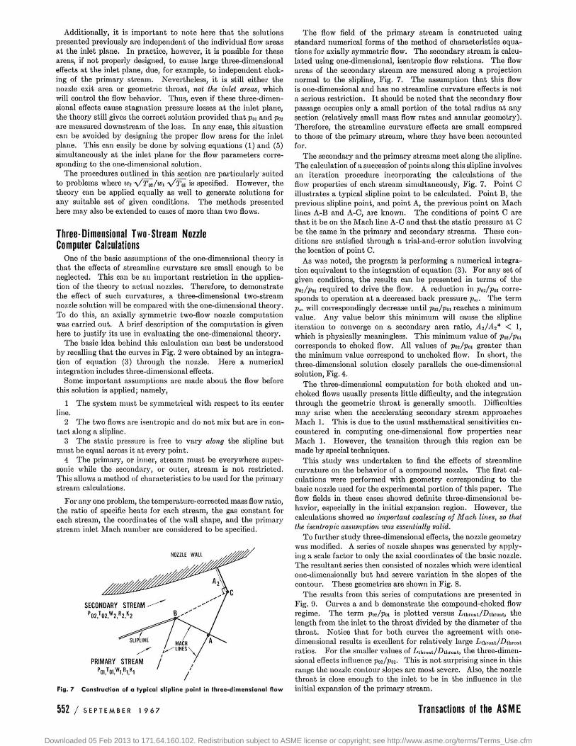
Fig. 7 Construction of a typical slipline point in three-dimensional f low
P R I M A R Y S T R E A M
The flow field of the primary stream is constructed using standard numerical forms of the method of characteristics equa-tions for axially symmetric flow. The secondary stream is calcu-lated using one-dimensional, isentropic flow relations. The flow areas of the secondary stream are measured along a projection normal to the slipline, Fig. 7. The assumption that this flow is one-dimensional and has no streamline curvature effects is not a serious restriction. It should be noted that the secondary flow passage occupies only a small portion of the total radius at any section (relatively small mass flow rates and annular geometry). Therefore, the streamline curvature effects are small compared to those of the primary stream, where they have been accounted for.
The secondary and the primary streams meet along the slipline. The calculation of a succession of points along this slipline involves an iteration procedure incorporating the calculations of the flow properties of each stream simultaneously, Fig. 7. Point C illustrates a typical slipline point to be calculated. Point B, the previous slipline point, and point A, the previous point on Mach lines A-B and A-C, are known. The conditions of point C are that it be on the Mach line A-C and that the static pressure at C be the same in the primary and secondary streams. These con-ditions are satisfied through a trial-and-error solution involving the location of point C.
As was noted, the program is performing a numerical integra-tion equivalent to the integration of equation (3). For any set of given conditions, the results can be presented in terms of the Pai/Pn required to drive the flow. A reduction in p02/poi corre-sponds to operation at a decreased back pressure p„. The term p„ will correspondingly decrease until pm/poi reaches a minimum value. Any value below this minimum will cause the slipline iteration to converge on a secondary area ratio, A2/A2* < 1, which is physically meaningless. This minimum value of pm/poi corresponds to choked flow. All values of pm/Vn greater than the minimum value correspond to unchoked flow. In short, the three-dimensional solution closely parallels the one-dimensional solution, Fig. 4.
The three-dimensional computation for both choked and un-choked flows usually presents little difficulty, and the integration through the geometric throat is generally smooth. Difficulties may arise when the accelerating secondary stream approaches Mach 1. This is due to the usual mathematical sensitivities en-countered in computing one-dimensional flow properties near Mach 1. However, the transition through this region can be made by special techniques.
This study was undertaken to find the effects of streamline curvature on the behavior of a compound nozzle. The first cal-culations were performed with geometry corresponding to the basic nozzle used for the experimental portion of this paper. The flow fields in these cases showed definite three-dimensional be-havior, especially in the initial expansion region. However, the calculations showed no important coalescing of Mach lines, so that the isentropic assumption was essentially valid.
To further study three-dimensional effects, the nozzle geometry was modified. A series of nozzle shapes was generated by apply-ing a scale factor to only the axial coordinates of the basic nozzle. The resultant series then consisted of nozzles which were identical one-dimensionally but had severe variation in the slopes of the contour. These geometries are shown in Fig. 8.
The results from this series of computations are presented in Fig. 9. Curves a and b demonstrate the compound-choked flow regime. The term pm/poi is plotted versus Z*throat/-Dthroat, the length from the inlet to the throat divided by the diameter of the throat. Notice that for both curves the agreement with one-dimensional results is excellent for relatively large Lthro»t/-Dthro»t ratios. For the smaller values of Lthroot/Duiroat, the three-dimen-sional effects influence pce/poi. This is not surprising since in this range the nozzle contour slopes are most severe. Also, the nozzle throat is close enough to the inlet to be in the influence in the initial expansion of the primary stream.
5 5 2 / S E P T E M B E R 1 9 6 7 Transactions of the A S M E
Downloaded 05 Feb 2013 to 171.64.160.102. Redistribution subject to ASME license or copyright; see http://www.asme.org/terms/Terms_Use.cfm

T H E B A S I C N O Z Z L E A N D T Y P I C A L V A R I A T I O N S E X P E R I M E N T A L R E S U L T S
ONE D I M E N S I O N A L T H E O R Y
A E X I T —
S H O R T E N E D 1—H "-THROAT | E L O N G A T E D N O Z Z L E
N O Z Z L E ; " - E X I T B A S I C N O Z Z L E
BASIC NOZZLE DIMENSIONS :
A ' r ' A T H R O A T = 0.431
M / * E X I T - 0226
U H R O A T / D T H R O A T = 0.374
L E X I T - " E X I T = 0.695
Kj=K2= 14 Rl=R2=53.3
Fig . 8 N o z z l e s used in t h r e e - d i m e n s i o n a l c o m p a r i s o n
O N E DIMENSIONAL
AXIALLY S Y M M E T R I C
0.6
P02/P01 0.4
W j ^ / W . / f o , =0.052
C O M P O U N D
C H O K E D
W 2 V / T 0 ! / W , Y F O , 0 . 3 1 5
P02 P 0 1
W 2 y T o 2 / w , y T m =0.052
C O M P O U N D
U N C H O K E D
Pm/P» 4 0
W 2 / W W i v / T o i =0.315
P01/R0 2 7 5
W 2 A 2 W , / T 0 , = 0-315
P02/P01
Pfl2 /Poi
W 2 y T 0 2 / W , y T | 1 , = 0.209
w2yf02/w lv/r0i = 0.052
—0 o-
0 0.4 0.8 1.2 0 0.4 0 8 1.2
L T H K U A T ' D T H R O A T L T H R O A T / D J H R O A T
Fig . 9 C o m p a r i s o n of o n e - d i m e n s i o n a l a n d t h r e e - d i m e n s i o n a l resul ts
Curves o and d demonstrate the compound-unchoked flow regime. Again, agreement with the one-dimensional results is excellent. The discrepancies for short nozzles are not so pro-nounced here since the exit conditions, and not the throat condi-tions, are dominant. Some departure from the one-dimensional line is seen for the longer nozzles. It is felt that this may be due to accumulating inaccuracies resulting from the finite difference techniques used. For long nozzles, these errors may become significant by the time the exit plane is reached.
The agreement between the one-dimensional and the axially symmetric solutions is excellent for the range of nozzle variation examined. Three-dimensional effects have little influence on the level of P02/P01 for the nozzle geometries considered.
Experimental Results Extensive test programs conducted 011 a wide variety of nozzle
types and geometries have shown excellent agreement between the one-dimensional compound-flow theory and experimental re-sults. These test programs have included convergent, cylindrical, and convergent-divergent nozzles with both two and three streams.
The success of the one-dimensional theory is not surprising. The previous section indicated that the behavior of compound flow nozzles is reasonably insensitive to three-dimensional effects. For nozzles with small wall frictional effects, and fairly undis-torted inlet flow, only the effects of mixing can cause the one-dimensional model to be inaccurate when applied to real nozzles. It is reasonable to assume that, since the flow is turbulent, mixing is confined to a shear layer between adjacent streams which grows with axial position at an angle of less than 8 deg [3]. It is there-fore clear that the shapes of the and the nozzle length are the major factors which determine the degree of mixing. The ten-dency of the mixing will be to pump the low-velocitj' streams and
2 4 6 8 10 Poi/Pco
Fig . 1 0 C o m p a r i s o n of c o m p o u n d - c o m p r e s s i b l e f l o w t h e o r y w i t h e x p e r i m e n t a l resul ts
to retard the high-velocity streams. The extent of the influence of mixing depends primarily on the flow rates of each stream. The behavior of streams with proportionately low rates will be greatly affected by mixing while those with higher flow rates will ex-perience only small effects. Note, however, that in the important case of choked Uow, mixing effects downstream of the nozzle throat can exert no influence whatsoever upon the behavior of the flow. Thus, for many nozzle applications, mixing will influence only a small portion of the flow.
Because of the space limitations of this paper, a fully compre-hensive comparison of one-dimensional theory with experimental data from a wide variety of compound-flow nozzle types and geometries is impractical. According^, the basic nozzle previ-ously discussed was selected for comparison. Being convergent-divergent, it is a representative two-stream nozzle in that it can display both the choked and unchoked regimes of compound flow.
Tests were run over a wide range of temperature-corrected mass flow ratios while varying pm/p^ from approximately 2 to 10. This allowed the nozzle to exhibit both choked and unchoked behavior at each mass flow ratio. Fig. 10 is a comparison of ex-perimental results with predictions based upon the one-dimen-sional compound-flow theory. The choked flow regime is the straight portion of the theoretical lines and, as expected, occurs at the higher poi/paThe unchoked flow regime is the curved portion of the lines which occurs at the lower primary nozzle stagnation pressure ratios.
It can be seen that the one-dimensional theory shows excellent agreement with the experimental data, particularly in the choked flow regime. Correlation with experimental data in the un-choked flow regime is somewhat less accurate. However, in view of the mixing effects previously discussed, this was to be expected. During choked flow, all mixing downstream of the nozzle throat can have no effect 011 the flow. Thus the effective mixing length for choked flow is merely the distance from the inlet plane to the throat. On the other hand, during unchoked flow, all mixing downstream of the nozzle throat will have a very definite effect on the flow behavior. With unchoked flow, then, the effective mixing length is the entire length of the nozzle.
As anticipated, we also observe that mixing has little effect at the higher mass flow ratios but exerts increasing influence as mass flow ratio decreases. Furthermore, the important effect of mixing is to pump the secondary flow and therefore reduce the required pm/poi-
It is noted that the model tested was not an ideally designed nozzle; i.e., the primary stream was independently choked and slightly underexpanded at the inlet plane. However, the model used in the experiments was operated sufficiently near to its isentropic design conditions that stagnation pressure losses in the supersonic stream were probably not important, and shock losses
Journal of Applied Mechanics SEPTEMBER 1 9 6 7 / 5 5 3
Downloaded 05 Feb 2013 to 171.64.160.102. Redistribution subject to ASME license or copyright; see http://www.asme.org/terms/Terms_Use.cfm
are impossible in the subsonic secondary stream. This was indi-cated in the previous section, where the three-dimensional solu-tion showed no significant coalescing of the primary stream Mach lines under conditions for which the tests were run. Although Poi/Pos is measured upstream of the inlet plane, these argu-ments justify our neglect of total pressure losses in all calcula-tions.
Concluding Remarks A new one-dimensional theory describing the behavior of com-
pound-compressible nozzle flows has been developed and its implications have been examined from a number of viewpoints.
The theory yields simple algebraic methods for calculating the operation of compound-compressible nozzles. Comparison of the algebiaic results with those of three-dimensional flow field com-putations indicates that the effects of streamline curvature are not important for many practical nozzle configurations. Com-parison of the algebraic results with experimental data for flows with unimportant mixing effects shows that the theory can
accurately predict the behavior of real devices. A complete definition of the range of applicability of the simple
theory requires a great deal of experimental experience. For ex-ample, little information is available about the rate of growth of the mixing zone between the high-velocity streams, and no in-formation is available about the detailed nature of compound-shock waves. Furthermore, no predictions about the thrust or nozzle efficiency can be made when the flow is choked until the losses caused by a compound-shock wave are known. Conse-quently, it appears that the compound-compressible nozzle pro-vides a number of interesting and important areas of research.
References 1 Pearson, H., HoUiday, J. B„ and Smith, S. F., "A Theory of
the Cylindrical Ejector Supersonic Propelling Nozzle," Journal of the Royal Aeronautical Society, London, Section 62, 1958, p. 746.
2 Shapiro, A. H., The Dynamics and Thermodynamics of Com-pressible Fluid Flow, Ronald Press Co., New York, 1953.
3 Sclilichting, H., Boundary Layer Theory, 4th ed., McGraw-Hill, New York, 1960, pp. 598-600.
5 5 4 / S E P T E M B E R 1 9 6 7 Transactions of the A S M E
Downloaded 05 Feb 2013 to 171.64.160.102. Redistribution subject to ASME license or copyright; see http://www.asme.org/terms/Terms_Use.cfm