computational analysis of injection-molding residual …cecas.clemson.edu/~gli/papers/jmpt08.pdfin...
TRANSCRIPT

Cdb
MMa
Cb
c
a
A
R
R
1
A
K
P
R
W
A
1
Wt
T
0d
j o u r n a l o f m a t e r i a l s p r o c e s s i n g t e c h n o l o g y 2 0 3 ( 2 0 0 8 ) 19–36
journa l homepage: www.e lsev ier .com/ locate / jmatprotec
omputational analysis of injection-molding residual-stressevelopment in direct-adhesion polymer-to-metal hybridody-in-white components
. Grujicica,∗, V. Sellappana, B. Pandurangana, G. Lia, A. Vahidia, Norbert Seyrb,arc Erdmannc, Jochen Holzleitner c
International Center for Automotive Research CU-ICAR, Department of Mechanical Engineering,lemson University, Clemson, SC 29634, United StatesBMW Group Forschung und Technik, Hanauer Straße 467, 80788 Munchen, GermanyBMW AG, Forschungs- und Innovationszentrum, Knorrstraße 147, 80788 Munchen, Germany
r t i c l e i n f o
rticle history:
eceived 28 July 2007
eceived in revised form
3 September 2007
ccepted 16 September 2007
eywords:
olymer metal hybrids
esidual stresses
arpage
utomotive structural components
a b s t r a c t
To overcome some of the main limitations of the current polymer metal hybrid (PMH) tech-
nologies, a new approach, the so-called “direct-adhesion” PMH process, has been recently
proposed [Grujicic, M., Sellappan, V., Arakere, G., Seyr, N., Erdmann, M., in press. Com-
putational feasibility analysis of direct-adhesion polymer-to-metal hybrid technology for
load-bearing body-in-white structural components, J. Mater. Process. Technol.]. Within this
approach, the necessary level of polymer-to-metal mechanical interconnectivity is attained
through the use of polymer-to-metal adhesion promoters. Such promoters are applied to the
metal stamping prior to their placement into the injection mold for plastic-subcomponent
injection molding. The resulting enhanced polymer-to-metal adhesion affects the way
injected plastic develops residual stresses while it is cooled from the plastic-melt temper-
ature down to room temperature. In the present work, injection-molding mold-filling and
material-packing analyses are combined with a structural analysis involving polymer/metal
adhesion analysis to assess the extent of residual stresses and warping in a prototypi-
cal direct-adhesion PMH component. The magnitude and the distribution of such stresses
and distortions are critical for the component assembly, performance and durability. The
results obtained show that adhesion at the metal-stamping/plastics-subcomponent inter-
faces, whose presence is the bases for the direct-adhesion PMH technology, has a profound
effect on the distribution and magnitude of residual stresses/distortions in the PMH com-
ponent and that it must be taken into account when the component and its manufacturing
esig
(PMH) design technologies try to take full advantage of the
processes are being d
. Introduction
hile metals and plastics are typically fierce competi-ors in automotive manufacturing, the polymer-metal-hybrid
∗ Corresponding author at: 241 Engineering Innovation Building, Clemsel.: +1 864 656 5639; fax: +1 864 656 4435.
E-mail address: [email protected] (M. Grujicic).924-0136/$ – see front matter © 2007 Elsevier B.V. All rights reserved.oi:10.1016/j.jmatprotec.2007.09.059
ned.
© 2007 Elsevier B.V. All rights reserved.
on University, Clemson, SC 29634-0921, United States.
two classes of materials by combining them in a singu-lar component/sub-assembly. Several patented PMH design/manufacturing technologies have already proven their abil-
i n g
20 j o u r n a l o f m a t e r i a l s p r o c e s sity to allow the automotive original equipment manufacturers(OEMs) to engage flexible assembly strategies, decrease capi-tal expenditures and reduce labor required to manufacture avehicle. The key feature of PMH structures is that the materialsemployed complement each other so that the resulting hybridmaterial can offer structural performance which is not presentin either of the two constituent materials independently.Among many technical and economic benefits associated withthe use of the PMH technologies, the following appear to bethe most important: (a) reduction of the number of compo-nents; (b) production of the integrated components ready toassemble; (c) weight reduction compared to the traditionalall-metal solutions; (d) additional design and styling freedom;(e) production of in-mold features like brackets, bosses andattachment points; (f) safety improvement due to lowered cen-ter of gravity of the vehicle; (g) a major (several fold) increase inthe bending strength of stamped metal sections. This effect iswell understood and is attributed to the plastic subcomponentwhich forces the metal to maintain its cross-section propertiesthroughout the loading cycle and delays the onset of failuredue to localized buckling; and (h) improved damping in theacoustic range (relative to their all-steel counterparts, oftenas high as four times lower initial decibel reading measuredin a simple hammer-strike test).
The main PMH technologies currently being employed bythe automotive OEMs and suppliers can be grouped into threemajor categories: (a) injection over-molding technologies; (b)metal over-molding technologies combined with secondaryjoining operations; and (c) adhesively bonded PMH structures.Since these were reviewed in great detail in our recent work(Grujicic et al., in press), they will be only briefly described inthis section.
In the injection over-molding process (originally developedand patented by Bayer (Zoellner and Evans, 2002)), a metal-stamping profile is placed in an injection mold and polymer(typically glass fiber reinforced nylon) is injected around theprofile. The plastic wraps around the edges of the sheet metaland/or through carefully designed extruded holes or buttons.There are no secondary operations required and the draw-ing oils/greases do not need to be removed from the metalstamping.
In the metal over-molding PMH technology (developed andpatented by Rhodia (Plastic-Metal Hybrid Material, 2007)), asteel stamping is placed in an injection mold in order to coatits underside with a thin layer of reinforced nylon. In a sec-ondary operation, the polymer-coated surface of the metalinsert is ultrasonically welded to an injection molded nylonsubcomponent. In this process, a closed-section structurewith continuous bond lines is produced which offers a highload-bearing capability. The hollow core of the part permitsfunctional integration-like cable housings and air or waterchannels.
In the adhesively bonded PMHs (developed and patented byDow Automotive (Recktenwald, 2005)), glass-fiber reinforcedpoly-propylene is typically joined to a metal stamping usingDow’s proprietary low-energy surface adhesive (LESA). The
acrylic-epoxy adhesive does not require pre-treating of the lowsurface-energy poly-propylene and is applied by high-speedrobots. Adhesive bonding creates continuous bond lines, mini-mizes stress concentrations and acts as a buffer which absorbst e c h n o l o g y 2 0 3 ( 2 0 0 8 ) 19–36
contact stresses between the metal and polymer subcompo-nents. Adhesively bonded PMHs also enable the creation ofclosed-section structures which offer high load-bearing capa-bilities and the possibility for enhanced functionality of hybridparts (e.g. direct mounting of air bags in instrument-panelbeams or incorporation of air or water circulation inside doormodules).
While the aforementioned PMH technologies have beenwidely used in various non-structural and load-bearingautomotive components, it is well established that they, nev-ertheless, display some serious shortcomings. For example,to maintain the structural integrity of the part, the holesneeded for polymer-to-metal interlocking in the injectionover-molding process are not allowed. Similarly, edge over-molding of the stamping may be restricted. In the caseof adhesively bonded PMHs, the adhesive cost, long cur-ing time and limited ability of the adhesive to withstandaggressive chemical and thermal environments encounteredin the paint-shop during body-in-white (BIW) pretreatmentand E-coat curing may create defective PMH components.Consequently, alternative lower-cost PMH technologies forstructural load-bearing BIW components which are compat-ible with the BIW manufacturing process chain are beingsought.
One of such technologies, which is the subject of thepresent work, is the so-called direct-adhesion PMH (DA-PMH)technology in which the joining between the metal andthermo-polymer subcomponents is attained through directadhesion of injection-molded thermoplastics to the metalwithout the use of interlocking rivets/over-molded edges orstructural adhesives (Grujicic et al., in press, submitted forpublication-a). There are several potential advantages offeredby this technology over the ones discussed above: (a) polymer-to-metal adhesion strengths (20–30 MPa) comparable withthose obtained in the case of thermo-setting adhesives arefeasible but only at a small fraction of the manufacturingcycle time; (b) the shorter cycle time and the lack of use ofan adhesive allow for more economical PMH-component pro-duction; (c) unlike the adhesive-bonding technology, joiningis not limited to simple and non-interfering contact surfaces;(d) reduced possibility for entrapping air in undercuts of acomplex surface; (e) no holes for the formation of interlockingrivets are required and, hence, structural integrity of the part isnot compromised; and (f) overall reduction in the constraintsplaced upon the design complexity of the PMH component.
In a typical DA-PMH process, selective portions of the metalstamping are degreased and coated with an adhesion pro-moter before the stamping is placed into the injection mold.Upon the injection of the molten plastics into the mold cav-ity and following a brief material packing stage, the plasticsbegin to contract (due to cooling). In a conventional injectionover-molding process, no significant adhesion exists betweenthe metal stamping and the plastic injection molded subcom-ponent. Consequently, the in-mold residual stresses tend todevelop mainly as a result of non-uniform cooling, large dif-ferences in the polymer-subcomponent wall thickness and the
level of material packing, as well as due to the restrictionsimposed to the polymer subcomponent by the mold duringshrinkage. In the case of a DA-PMH process, on the other hand,injected polymer adheres to the metal stamping and it is not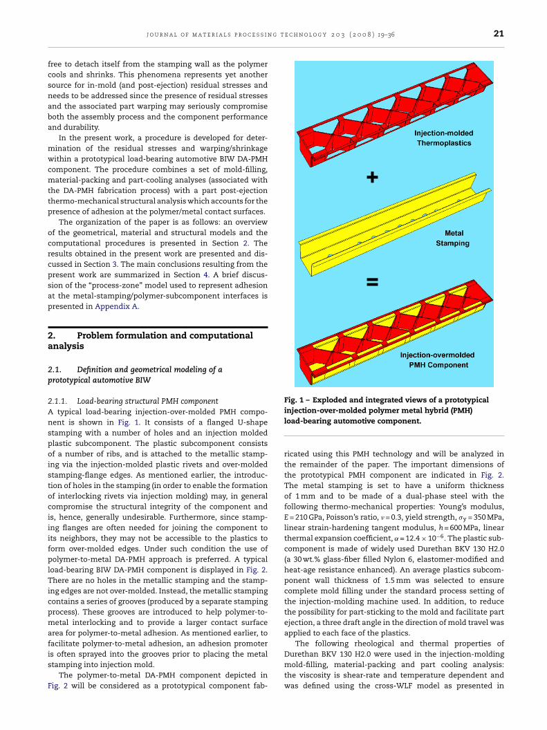
g t e c h n o l o g y 2 0 3 ( 2 0 0 8 ) 19–36 21
fcsnaba
mwcmttp
ocrcpsap
2a
2p
2AnspoistociiifplTicpmafis
F
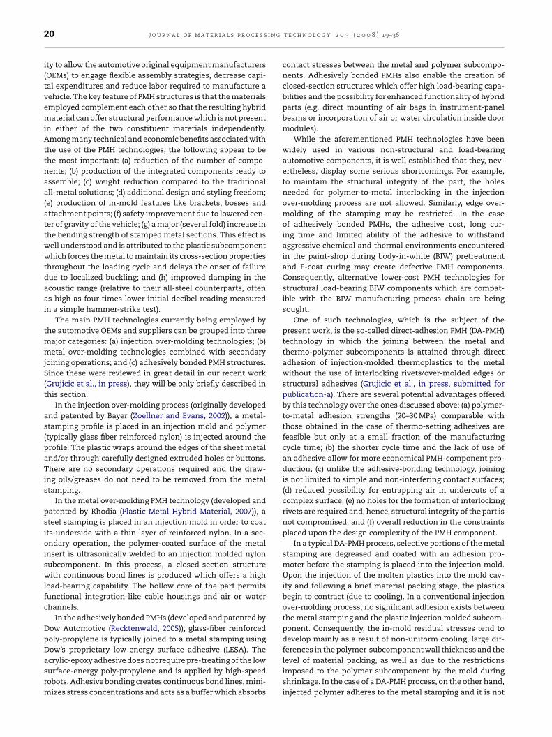
Fig. 1 – Exploded and integrated views of a prototypical
j o u r n a l o f m a t e r i a l s p r o c e s s i n
ree to detach itself from the stamping wall as the polymerools and shrinks. This phenomena represents yet anotherource for in-mold (and post-ejection) residual stresses andeeds to be addressed since the presence of residual stressesnd the associated part warping may seriously compromiseoth the assembly process and the component performancend durability.
In the present work, a procedure is developed for deter-ination of the residual stresses and warping/shrinkageithin a prototypical load-bearing automotive BIW DA-PMH
omponent. The procedure combines a set of mold-filling,aterial-packing and part-cooling analyses (associated with
he DA-PMH fabrication process) with a part post-ejectionhermo-mechanical structural analysis which accounts for theresence of adhesion at the polymer/metal contact surfaces.
The organization of the paper is as follows: an overviewf the geometrical, material and structural models and theomputational procedures is presented in Section 2. Theesults obtained in the present work are presented and dis-ussed in Section 3. The main conclusions resulting from theresent work are summarized in Section 4. A brief discus-ion of the “process-zone” model used to represent adhesiont the metal-stamping/polymer-subcomponent interfaces isresented in Appendix A.
. Problem formulation and computationalnalysis
.1. Definition and geometrical modeling of arototypical automotive BIW
.1.1. Load-bearing structural PMH componenttypical load-bearing injection-over-molded PMH compo-
ent is shown in Fig. 1. It consists of a flanged U-shapetamping with a number of holes and an injection moldedlastic subcomponent. The plastic subcomponent consistsf a number of ribs, and is attached to the metallic stamp-
ng via the injection-molded plastic rivets and over-moldedtamping-flange edges. As mentioned earlier, the introduc-ion of holes in the stamping (in order to enable the formationf interlocking rivets via injection molding) may, in generalompromise the structural integrity of the component ands, hence, generally undesirable. Furthermore, since stamp-ng flanges are often needed for joining the component tots neighbors, they may not be accessible to the plastics toorm over-molded edges. Under such condition the use ofolymer-to-metal DA-PMH approach is preferred. A typical
oad-bearing BIW DA-PMH component is displayed in Fig. 2.here are no holes in the metallic stamping and the stamp-
ng edges are not over-molded. Instead, the metallic stampingontains a series of grooves (produced by a separate stampingrocess). These grooves are introduced to help polymer-to-etal interlocking and to provide a larger contact surface
rea for polymer-to-metal adhesion. As mentioned earlier, toacilitate polymer-to-metal adhesion, an adhesion promoter
s often sprayed into the grooves prior to placing the metaltamping into injection mold.The polymer-to-metal DA-PMH component depicted inig. 2 will be considered as a prototypical component fab-
injection-over-molded polymer metal hybrid (PMH)load-bearing automotive component.
ricated using this PMH technology and will be analyzed inthe remainder of the paper. The important dimensions ofthe prototypical PMH component are indicated in Fig. 2.The metal stamping is set to have a uniform thicknessof 1 mm and to be made of a dual-phase steel with thefollowing thermo-mechanical properties: Young’s modulus,E = 210 GPa, Poisson’s ratio, � = 0.3, yield strength, �y = 350 MPa,linear strain-hardening tangent modulus, h = 600 MPa, linearthermal expansion coefficient, ˛= 12.4 × 10⁻⁶. The plastic sub-component is made of widely used Durethan BKV 130 H2.0(a 30 wt.% glass-fiber filled Nylon 6, elastomer-modified andheat-age resistance enhanced). An average plastics subcom-ponent wall thickness of 1.5 mm was selected to ensurecomplete mold filling under the standard process setting ofthe injection-molding machine used. In addition, to reducethe possibility for part-sticking to the mold and facilitate partejection, a three draft angle in the direction of mold travel wasapplied to each face of the plastics.
The following rheological and thermal properties of
Durethan BKV 130 H2.0 were used in the injection-moldingmold-filling, material-packing and part cooling analysis:the viscosity is shear-rate and temperature dependent andwas defined using the cross-WLF model as presented in
22 j o u r n a l o f m a t e r i a l s p r o c e s s i n g
Fig. 2 – Exploded and integrated views of a prototypical
polymer-to-metal direct-adhesion polymer metal hybrid(PMH) load-bearing automotive component.our previous work (Grujicic et al., in press), specific heat,Cp = 1909 J/kg K, thermal conductivity, k = 0.14 W/mK, glasstransition temperature, Ttrans = 479.0 K. Likewise, the fol-lowing thermo-mechanical properties were used in thestructural mechanics analysis of the PMH part warp-ing/shrinking and residuals-stress development within thepart: Young’s modulus, E = 7 GPa, Poisson’s ratio, � = 0.4,yield strength, �y = 150 MPa, linear strain-hardening tangentmodulus, h = 100 MPa, linear thermal expansion coefficient,˛= 4 × 10⁻⁵. It should be noted, however, that the thermo-mechanical properties for Durethan BKV 130 H2.0 givenabove pertain to the properties of this material in its as-received (isotropic) condition. The actual properties usedin the thermo-mechanical analyses were both anisotropicand non-uniform throughout the part and were obtainedby combining the mold-filling results pertaining to the localorientation of the glass-fibers with a rule-of-mixture compu-tational scheme for determination of the effective (two-phase)material properties. A more detailed account of this procedure
is given in next section.As mentioned earlier, to enhance polymer-to-metaladhesion, an adhesion promoter is often used in the polymer-to-metal DA-PMH technologies. In the present work, it is
t e c h n o l o g y 2 0 3 ( 2 0 0 8 ) 19–36
assumed that an adhesion promoter is used; however, its use isincluded only implicitly into the thermo-mechanical analysisin the present work. In other words, no separate “geometricalpart” was created to represent the adhesion-promoter layer.Instead, its effect on enhancing polymer-to-metal adhesion isincluded by creating an adhesion interface between the poly-mer and metal. This adhesion interface is characterized by atraction-separation law whose main parameters are the adhe-sion strengths (i.e. a normal and two shear interfacial stressesat which polymer/metal decohesion/de-bonding begins totake place; the corresponding normal separation and sheardisplacements and the resulting normal and shear worksof decohesion). Since both normal and shear decohesionmodes are generally represented using a “universal” traction-separation law (Grujicic et al., submitted for publication-b),only two sets of parameters mentioned above are indepen-dent (e.g. for the normal separation mode, the work of normaldecohesion is functionally related to the normal adhesionstrength and to the critical (normal) polymer/metal inter-facial separation). Following our previous work (Grujicic etal., submitted for publication-b), typical values are used forthe normal adhesion strength, �n = 10 MPa, shear adhesionstrength, �sh = 10 MPa, critical normal separation, dn = 5 nm,and critical shear displacement, dsh = 25 nm. A more detaildescription of the interfacial separation (i.e. decohesion) lawused in the present work and the finite elements used to repre-sent this law in the thermo-mechanical analysis is presentedin Appendix A.
2.2. Pre-processing of PMH component model formold-filling and thermo-mechanical analyses
Before computational analyses of the mold-filling and mate-rial packing stages of the prototypical PMH componentfabrication process by injection over-molding can be carriedout, geometrical models for the metal stamping and plasticssubcomponent had to be constructed. This was done usingCATIA, a computer-aided design (CAD) package from DassaultSystems (CATIA, 2007). Next, the geometrical models had tobe properly meshed and pre-processed (i.e. locations of theinjection gates had to be specified, the thermal conditionsat the metal-stamping/plastic-subcomponent interface andmetal stamping/mold interface had to be defined, etc.). Someof the main aspects of the pre-processing procedure are dis-cussed in the remainder of this section.
After a CAD model of the metal stamping is generated, it ismeshed. To meet the requirements of the mold-filling/packingcomputer program, Moldflow Plastics Insight 6.1 (Moldflow, forshort) from Moldflow Corporation (Moldflow Plastics Insight,2006) used in the present work, the metal stamping is dis-cretized using ca. 120,000 triangular three-node first-ordersingle-layer (shell) elements with an average edge length ofca. 1.0 mm.
In order to properly model the development of residualstresses within the PMH part and, specifically, in order tomodel the metal-stamping grooves, the polymer subcompo-
nent is modeled as a solid part and discretized using tetrahe-dron four-node first-order (continuum) elements. To ensure aperfect mesh matching at the metal/polymer interfaces, thetetrahedron edge length was also kept around 1.0 mm.
j o u r n a l o f m a t e r i a l s p r o c e s s i n g t
Fig. 3 – Triangular mesh used for discretization of the metalst
atdpc
ipcms
oo(umcmtmcrpd(fl
mopcbatptMtMomp
tamping and tetrahedron mesh used for discretization ofhe injection-molded thermoplastic subcomponent.
The triangular mesh used to discretize the metal stampingnd the tetrahedron mesh used to discretize the thermoplas-ic subcomponent for a portion of the PMH component areepicted in Fig. 3. As mentioned earlier, the two meshes matcherfectly across the metal-stamping/polymer-subcomponentontact interfaces.
The presence of mesh matching at the metal/plasticnterfaces is highly critical since the coincident metal- andlastic-part nodes are used to construct a set of interfacialohesion elements. There were XXX such elements in theodel and they were all triangular-prism six-node traction-
eparation interfacial elements, Appendix A.All the aspects of pre-processing described above and the
nes presented in the remainder of this section were carriedut using Hypermesh program from Altair engineering Inc.
Hypermesh, 2007). For the injection-mold filling/packing sim-lations, the remainder of the pre-processing included: place-ent of the injection points, definition of thermal boundary
onditions at the metal-stamping/plastic-subcomponent andetal-stamping/tool interfaces, definition and application of
he rheological and thermal properties of the participatingaterials, and specification of the injection-molding pro-
ess parameters (e.g. plastic-melt temperature, injection flowate, velocity/pressure switchover, packing-stage duration,art-ejection condition, etc.). Once the pre-processing proce-ure is completed within Hypermesh, a Moldflow input file
in the .udm format) is created and imported in the Mold-ow.
As far as the pre-processing procedure for the thermo-echanical analysis is concerned, it included the construction
f the interfacial cohesion zone, thermo-mechanical materialroperty specification, definition of the initial and boundaryonditions, and loading. As mentioned earlier, the interactionetween melt flow and glass-fiber reinforcements lead to thelignment of the fibers with the local flow direction, and, inurn, to the anisotropy in plastic-material thermo-mechanicalroperties. The information regarding the spatial distribu-ion of the (anisotropic) material properties resulting from theoldflow mold-filling /packing calculations (stored in a .xml
ype file) is converted using a general mathematical package
atlab (MATLAB, 2006) into a material-data file. The syntaxf the material file was made consistent with the require-ents of Abaqus/Standard (ABAQUS, 2006), the finite element
rogram used in the present thermo-mechanical analysis of
e c h n o l o g y 2 0 3 ( 2 0 0 8 ) 19–36 23
residual-stress development. Following the same procedure,the spatial distribution of temperature within the plastics sub-component and metal stamping attained using the Moldflowset of analyses at the end of the packing stage are exported as atemperature initial-condition file consistent with the Abaqusinitial-condition data file format. As far as the boundary con-ditions are concerned, six degrees of freedom for one of themetal-stamping nodes are constrained to prevent the transla-tion and rotation of the PMH part.
Upon the completion of the pre-processing procedures, foreach case, a mold-filling/material-packing analysis is carriedout to determine the spatial distributions of the (anisotropic)thermo-mechanical material properties and of the temper-ature. These results are then imported into Abaqus and astatic thermo-mechanical analysis is carried out in order to:(a) determine the spatial distribution of residual stresses dur-ing the part cool-down to room temperature and (b) establishif decohesion/de-bonding has taken place at the plastic/metalinterfaces and to what extent. It should be noted that, in theprocedure described above, it is assumed that, due to the pres-ence of high packing pressures, shrinkage of the plastic doesnot take place during the filling and packing stages of theinjection-molding process.
2.3. Modeling of injection-molding fabrication of BIWpolymer metal hybrid
2.3.1. Structural componentFabrication of the PMH structural components by thermo-plastics injection molding is a widely used in the automotiveindustry. A typical PMH injection-molding process involvesthe following distinct stages: (a) metal stamping(s) placementinto the mold; (b) filling of the mold with molten thermoplas-tics; (c) packing—the injection of additional plastic materialinto the mold under high pressure to compensate for thecooling-induced volumetric shrinkage of the plastics; (d) cool-ing which gives rise to the solidification of the plastic materialresiding in the mold; (e) ejection of the PMH part/componentfrom the mold after the plastics has solidified. During the fill-ing, packing and cooling stages of the PMH injection-moldingprocess, the material(s) (in particular the plastics) is sub-jected to complex thermo-mechanical loading which givesrise to the changes in local specific volume (density) and partshape, as well as to the development of the in-mold resid-ual stresses in the part. In other words, while the PMH partresides in the mold, its (thin-wall) plastic subcomponent isconstrained within the mid-plane causing the (residual, built-in) stresses to develop in the part during solidification ofthe plastics. Upon ejection, these stresses tend to relax (atleast partially) causing distortion/warping and further shrink-age of molded part. Additional warping and shrinking ofthe part occurs during cooling of the ejected molded partfrom the ejection temperature down to the room tempera-ture.
To take into account the fact that the PMH injection moldedplastic subcomponent, analyzed in the present work, was
made of glass-fiber filled thermo-plastics, and hence, maypresent some challenges during mold filling, possess residualstresses at the moment of component ejection from the moldand contain a heterogeneous, anisotropic material and a non-
i n g
24 j o u r n a l o f m a t e r i a l s p r o c e s suniform spatial distribution of the temperature, the followinganalyses were conducted: (a) determination of the opti-mal placement and the optimal number of plastics-injectionpoints; (b) mold-filling analysis to obtain the filling time andspatial distribution of the glass-fiber orientation throughoutthe plastics subcomponent; and (c) plastic-material packingand cooling analyses to ensure that the mold-cavity is com-pletely filled with the plastics at the instant of PMH partejection from the mold. As mentioned earlier, all of theseanalyses were carried out using Moldflow Plastics Insight 6.1(Moldflow Plastics Insight, 2006). To conduct the subsequentthermo-mechanical analysis of the residual-stress devel-opment and part shrinkage/warping, the following resultsobtained using Moldflow were passed to Abaqus/Standard(ABAQUS, 2006): (a) spatial distribution of the plastic-materialorthotropic mechanical properties (Young’s moduli: E11, E22,and E33; Shear moduli: G12, G13, and G23; and Poisson’s ratio:�12, �13, and �23, where direction 1 coincides with the localglass-fiber directions), (b) spatial distribution of the plasticmaterial orthotropic thermo-mechanical properties (thermalexpansion coefficient, ˛1, ˛2, and ˛3), (c) spatial distribu-tion of the local-to-global rotation matrices, and (d) spatialdistribution of the temperature through the entire PMHpart.
Since the detail for all the Moldflow-based analyses listedabove were overviewed in great details in our recent work(Grujicic et al., in press), only a brief discussion of each willbe given in the remainder of this section.
2.3.2. Injection-molding process parameters and settingsIn the injection-molding analysis carried out in the presentwork, it was assumed that a Netstal commercial injection-molding machine Model 4200H-2150 is used with thefollowing specifications: (a) the injection unit—maximummachine injection stroke = 248 mm, maximum machine injec-tion rate = 5024 cm3/s, machine screw diameter = 80 mm; (b)the hydraulic unit—maximum machine hydraulic pres-sure = 17.5 MPa, intensification ratio = 10.0, machine hydraulicresponse time = 0.2 s; and (c) the clamping unit—maximummachine clamp force = 3800 t. Also the injection mold-ing is assumed to be done under the following processparameters: filling stage—melt temperature = 563 K, injectionrate = 400 cm3/s, velocity/pressure switchover at 99% vol-ume filled; packing stage—time = 10 s, pressure = 80 MPa; coolingstage—mold surface temperature = 363 K, ejection tempera-ture = 458 K, fraction of solid phase at ejection = 1.0; moldmaterial—tool steel P20; thermoplastics material—Durethan BKV130 H2.0 (an elastomer-modified Nylon 6 filled with 30 wt.% ofglass-fibers and heat-age stabilized).
2.4. Optimal placement and number of injection points
Before simulations of the injection-molding process can becarried out, the optimal placement and the number of injec-tion points has to be determined. The gate location analysisemployed in the present work uses the part geometry, the
selected material and the specified process settings and relieson the following criteria: molding feasibility and the achieve-ment of balanced flow, so that areas furthest away fromthe gate(s) (i.e. injection point(s)) are filled at approximatelyt e c h n o l o g y 2 0 3 ( 2 0 0 8 ) 19–36
the same time (Moldflow Plastics Insight, 2006). To ensurethat small enough plastics-wall-thicknesses can be injectionmolded, two gates (one attached to the second and the other tothe fifth rib x-shaped intersection) were utilized in the presentwork, Fig. 2.
2.4.1. Mold filling analysisThe mold filling process is governed by the mass, momen-tum and energy conservation equations, which were reviewedin our recent work (Grujicic et al., in press). When injectionmolding of thermo-plastics filled with fibers is considered, asis the present case, the flow field is generally assumed to beindependent of the orientation distribution of the fibers. Inother words, the mold-filling and packing analyses are de-coupled from the fiber orientation analysis. This assumptionis strictly justified only in the case of injection molding ofthe thin-walled parts, as is the present case, in which thefibers are oriented nearly parallel to the mid-plane and, hence,their interaction with the melt flow is limited (Grujicic et al.,in press; Lipscomb et al., 1988; Rosenberg et al., 1990; Zheng,1991; Phan-Thien et al., 1991; Phan-Thien and Graham, 1991;Altan et al., 1992). The conditions which have to be satisfiedin order for the influence of the fibers on the fluid motion tobe neglected can be found in Tucker (1991).
When the mold filling of thin-wall parts is analyzed, as isthe present case, the following two “lubrication” approxima-tions are generally made: (a) through-the-thickness-variationsin pressure are neglected and (b) the pressure field is takento satisfy Hele-Shaw (elliptic) equation (Moldflow PlasticsInsight, 2006). These approximations were used in the presentwork since they greatly simplify the effort needed to obtain thesolution for the governing equations.
Mold-filling governing differential equations were sub-jected to the following boundary conditions in the presentwork: (a) either the inlet-flow rate or the pressure bound-ary conditions are defined at the injection points (gates); (b)a zero-pressure condition is defined on the advancing flowfront; and (c) a zero-normal-pressure gradient is specified overthe mold-cavity-surface. These conditions do not ensure ano-slip condition over the mold-cavity-surface, which mayallow the fluid to “slip”. The resulting inaccuracies in thevelocity-field predictions, however, were found not to be sig-nificant (Grujicic et al., in press; Guell and Lovalenti, 1995).Since the aforementioned lubrication approximations limitthe analysis to the consideration of only the flow paral-lel with the local mid-plane, the approach used in thepresent work cannot be used to model the fountain flow(a flow type containing velocity components normal to thelocal mold wall). To reduce/eliminate the resulting inaccura-cies in the temperature and the fiber-orientation predictionsin the outermost layers of an injection molded part, thelocal approximation proposed in references Grujicic et al.(in press) and Crochet et al. (1994) was used in the presentwork.
To obtain temporal and spatial evolutions of the pres-sure during filling, the Hele-Shaw (elliptic) equation is solved
numerically using the conventional Galerkin finite elementmethod (within a local coordinate system in which the x1axis coincides with a line connecting the first two nodesof a given element and the x1 and x2 axes define the

g t
mctecds
cWritfita
devssmsUaoc(octa
2FiktFZpaast
wIcttvoaurm
p
j o u r n a l o f m a t e r i a l s p r o c e s s i n
id-plane). Four-node tetrahedron elements are used to dis-retize the plastic injection-molded subcomponent whilewo-node beam elements to model the runner system. Beforelement-based equations are assembled, a local-to-globaloordinate transformation is applied to obtain a full three-imensional computational model in the global coordinateystem.
The flow front is tracked using the standard node-centeredontrol-volume approach (Moldflow Plastics Insight, 2006).ithin this approach, within each time increment, the flow
ate into each node located on the flow front is calculated. Thiss used in conjunction with a given time step to determine ifhe control volume associated with the node in question islled. If the control volume is filled, the flow front is advancedo the node in question. Otherwise, the flow front is notdvanced.
To obtain spatial and temporal evolutions of temperatureuring mold filling (and packing), the energy conservationquation is solved numerically in such a way that the con-ection and viscous dissipation terms from a previous timetep are treated as source terms during the current timetep. Fast heat conduction over the metal stamping andold surfaces is accounted for using a cycle-averaged (con-
tant and uniform) temperature boundary condition at the-shape/polymer and mold/polymer interfaces. The cycle-veraged temperature of the U-shape and mold surfaces isbtained by solving a three-dimensional steady-state heatonduction equation using a boundary element methodGrujicic et al., in press; Rezayat and Burton, 1990). The effectf thermal contact resistance at the metal-stamping/moldontact surfaces (which leads to higher plastic-melt tempera-ures) is obtained using the procedure proposed by Grujicic etl. (2005).
.4.2. Fiber orientation distribution analysisor accurate predictions of the shrinkage and warping of annjection-molded part made of fiber-filled thermo-plastics,nowledge of the (flow-induced) fiber-orientation distribu-ion throughout the part is critical (Grujicic et al., in press;olgar and Tucker, 1984; Fan et al., 1998; Phan-Thien andheng, 1997). Since most commercial fiber-filled thermo-lastics commonly used for injection molding can be classifieds semi- or highly concentrated suspensions, fiber/fiber inter-ctions and spatial constraints to the fiber motion mayignificantly affect the final fiber-orientation distribution inhe part.
Fiber/fiber interactions are accounted for, in the presentork, using Folgar and Tucker model (Folgar and Tucker, 1984).
n this model, A suspension-specific isotropic parameter, CI,alled the “Interaction Coefficient” is introduced in the diffusionerm of the equation of motion for an isolated fiber in a New-onian fluid originally proposed by Jeffery (Jeffery, 1922). Thealue for CI is assessed using direct numerical–simulationsf fiber/fiber interactions within simple-shear flow (Fan etl., 1998) in which short-range interactions are quantifiedsing a lubrication model (Yamane et al., 1994) while long-
ange interactions were calculated using a boundary elementethod.The orientation of a fiber is defined using the unit vector
which is collinear with the fiber axis. The fiber-orientation
e c h n o l o g y 2 0 3 ( 2 0 0 8 ) 19–36 25
probability-distribution function is then defined using the sec-ond, −aij = 〈pp〉, and the fourth, aijkl = 〈pppp〉, order orientationtensors, where the angular brackets denote the ensemble aver-age. The temporal evolution of fiber orientation is defined bythe Folgar-Tucker equation (Advani and Tucker, 1987). To solvethis equation, the fourth-order tensor needs to be expressed interms of the second-order tensor. The “closure approximation”proposed in Grujicic et al. (in press) and Doi (1981) is used in thepresent work. Following determination of the fiber orientationunit normal, p (as a function of the initial fiber orientation,aspect ratio, the number density in the suspension and theshear-strain magnitude), the components of the second- andfourth-order orientation tensors aij and aijkl are computed.These are next used in an anisotropic rotary diffusion equa-tion to determine the magnitude of the fiber/fiber interactioncoefficient CI, and, in turn, the final fiber-orientation distribu-tion.
The fiber-orientation distribution equation is solvednumerically using the explicit Euler time-differencing schemewith a time step which is smaller than that used for the flowfront advancement analysis and which satisfies the appro-priate Courant stability criterion. For the fiber-orientationgoverning equation, the fiber-orientation tensors in the ele-ments which are associated with the injection gates have to bespecified. While the exact fibers orientations at the gates loca-tions are usually unknown, the choice of the initial conditionhas been found to have little impact on the final orientationdistribution of the fibers (Grujicic et al., in press; Zheng et al.,1999).
As mentioned earlier, the Hele-Shaw approximation doesnot include the effect of the lateral mold-walls on the advance-ment of flow field which, in turn, can lead to incorrectpredictions of the fibers orientation in the outermost layersof an injection-molded part. This, consequently, may lead toincorrect prediction of the part warping. To overcome theseshortcomings, two ad hoc remedies are used in the presentwork: (a) a vanishing tangential velocity along the mold wallsis imposed during fiber-orientation calculations when com-puting velocity gradients from the velocity field; and (b) an“infinite-aspect-ratio” assumption is used for the fibers nearthe mold walls (Grujicic et al., in press; Lipscomb et al.,1988).
2.4.3. Plastics material packing analysisWhile the packing phase of the injection-molding processis governed by the same conservation equations as the fill-ing phase, an additional equation, the equation of state (alsoknown as the P–V–T relation), must be defined in order toinclude the effect of melt compressibility. The P–V–T relationdefines a functional relationship between the specific volume,V, temperature, pressure, and cooling rate.
A two-domain Tait P–V–T relation (Grujicic et al., in press;Moldflow Plastics Insight, 2006) was used in the present work.It should be noted that a number of material properties (suchas volume thermal expansion coefficients and compressibil-ity) and their temperature and pressure dependencies are
derived from the equation of state. Also, the P–V–T relationis used to represent various phase transformations such asfreezing/melting, crystallization, and ductile-to-glass transi-tion.
i n g
26 j o u r n a l o f m a t e r i a l s p r o c e s s2.5. Micro-mechanics analysis of the effectivematerials properties
As mentioned earlier, for injection molded thermo-plasticsfilled with fibers, isotropic material models are gener-ally not valid unless the embedded fibers are randomlyoriented. Typically, fiber-induced material anisotropy canhave a profound influence on the extent and distribu-tion of residual stresses and shrinkage/warping in injectionmolded parts. In the previous section, it was demonstratedhow non-random orientation-distributions of the fibers areinduced by the melt-flow kinematics during filling and, toa lesser extent during packing. In this section, the devel-opment/utilization of a micromechanical model which canbe used to estimate anisotropic elastic and thermal prop-erties of a fiber-filled/thermo-plastic-matrix composite fromthe properties of the constituent fiber and matrix materialsand the known fiber-orientation distribution was discussed(Papathanasiou and Guell, 1997).
Materials processed using injection molding are gener-ally considered to be transversely isotropic, i.e. their propertiesare equal in two directions (the transverse direction andthrough-the-thickness direction). The elastic response of suchmaterials is defined by five (temperature-dependent) elasticmoduli: the longitudinal Young’s modulus E11, the transverseYoung’s modulus E11, the in-plane shear modulus G12, the out-plane shear modulus G23, and the plane-strain bulk modulusK23. The Poisson’s ratios �12, �21 and �23 can, in turn, be deter-mined from these elastic moduli using standard relations (e.g.Zheng et al., 1999). These properties are defined with respectto a local coordinate system in which the 1 direction is takento coincide with the fiber axis and to be normal to the planeof isotropy (defined by the 2 and 3 directions).
The elastic and thermal properties of short-fiber filledthermoplastics are typically assessed using a two-stepmicro-mechanics procedure. First, the properties of the cor-responding material in which the fibers are fully aligned inone direction are assessed. Next, an orientation averagingprocedure is applied to include the effect of the actual fiber-orientation distribution at hand.
Step 1: Derivations of the properties of materials in whichthe fibers are fully aligned can be found in many sources (e.g.Papathanasiou and Guell, 1997). Thermo-elastic properties ofinjection-molded fiber-filled polymers are typically specifiedas longitudinal, ˛1, and transverse, ˛2, thermal expansioncoefficients and are defined in terms of the thermal expansioncoefficients for the fiber and the matrix as (Schapery, 1968):
˛1 = Ef˛f� + Em˛m(1 − �)Ef� + Em(1 − �)
(1)
and
˛2 = (1 + vm)˛m(1 − �) + (1 + vf)˛f� − ˛1v12 (2)
where subscripts f and m denote fiber and matrix, respectively,
� the fiber volume fraction, E the Young’s modulus and ε is thePoisson ratio.Step 2: For a transversely isotropic material with theisotropy-plane normal coinciding with the 1 direction, the fol-
t e c h n o l o g y 2 0 3 ( 2 0 0 8 ) 19–36
lowing form of Hooke’s law holds:
⎛⎜⎜⎜⎜⎜⎜⎜⎜⎝
�1
�2
�3
�4
�5
�6
⎞⎟⎟⎟⎟⎟⎟⎟⎟⎠
=
⎛⎜⎜⎜⎜⎜⎜⎜⎜⎜⎝
c(e)11 c
(e)12 c
(e)12 0 0 0
c(e)12 c
(e)22 c
(e)23 0 0 0
c(e)12 c
(e)23 c
(e)22 0 0 0
0 0 0 c(e)44 0 0
0 0 0 0 c(e)55 0
0 0 0 0 0 c(e)66
⎞⎟⎟⎟⎟⎟⎟⎟⎟⎟⎠
⎛⎜⎜⎜⎜⎜⎜⎜⎜⎝
ε1
ε2
ε3
ε4
ε5
ε6
⎞⎟⎟⎟⎟⎟⎟⎟⎟⎠
(3)
in which c(e)44 = (1/2)(c(e)
22 − c(e)23 ), c(e)
55 = c(e)66 and the contracted
notation (1 = 11, 2 = 22, 3 = 33, 4 = 23, 5 = 13 and 6 = 12) is used.The components of the elastic-stiffness matrix are defined
in terms of the elastic moduli as (Halpin and Kardos, 1976):
c(e)11 = (1 − v23)E11
1 − v23 − 2v12v21(4)
c(e)12 = v23E11
1 − v23 − 2v12v21(5)
c(e)22 = E22
2(1 − v23 − 2v12v21)+ G23 (6)
c(e)23 = E22
2(1 − v23 − 2v12v21)− G23 (7)
c(e)55 = G12 (8)
Once the properties of short-fiber uni-directionally reinforcedpolymers are determined, an orientation averaging procedureis used in conjunction with the known fibers orientation ten-sors to determine the corresponding assembly-average elasticand thermo-elastic material properties as (Advani and Tucker,1987):
〈c(e)ijkl
〉 = B1aijkl + B2(aijıkl + aklıij) + B3(aikıjl + ailıjk+ajlıik + ajkıil)
+B4ıijıkl + B5(ıikıjl + ıilıjk) (9)
and
〈˛ij〉 = (˛1 − ˛2)aij + ˛2ıij (10)
where B′is denote the five invariants of the stiffness tensor of
the uni-directionally reinforced polymers (Advani and Tucker,1987). It should be noted that the expressions given in Eqs.(9) and (10) are specific examples of the so-called “effectivematerial-properties averaging schemes”. Within such schemes,a composite material is considered as an aggregate of dis-crete constituent materials and different averaging schemesare based on different assumptions. For example, the ther-
mal expansion coefficient defined by Eq. (10) is obtained underthe assumption of a uniform stress and temperature gradientthroughout the fiber/matrix aggregate (Camacho et al., 1990;Eduljee et al., 1994).
g t
2a
Tmmsicmaitwinatgttiao
mdcmww
2fArrsptttf
�
wa
�
wirs(
j o u r n a l o f m a t e r i a l s p r o c e s s i n
.6. In-mold stress development and distributionnalysis
here are two main sources for residual stresses in injectionolded parts: (a) visco-elastic deformations of the ther-oplastic material during mold-filling and material-packing
tages can give rise to the development of the so-called “flow-nduced” residual stresses and (b) when the (inhomogeneous)ooling- and solidification-induced shrinkage of the poly-er is restricted by the mold and metal-stamping(s) and the
pplied packing pressure, the so-called “thermally and pressure-nduced” stresses are generated. Following the general practice,he flow-induced residual stresses are neglected in the presentork, since these are readily relieved while the part resides
n the mold at high temperatures prior to ejection. There areumerous reports of numerical investigations of the pressurend thermally induced stresses in injection molded parts inhe literature (e.g. Bushko and Stokes, 1996). These investi-ations clearly revealed the effects of mold constraints andhermo-plastics material models on the extent and distribu-ion of the residual stresses. However, there are no reportsn the open literature addressing the effect of plastics/moldnd/or plastics/metallic-stamping(s) adhesion on the devel-pment and the extent of residual stresses.
As discussed earlier, adhesion between the plastics andetal (tools and stampings) merely alters the boundary con-
itions in the in-mold stress analysis. Consequently, andonsidering the fact that a fairly detail description of the in-old stress development analysis was presented in our recentork (Grujicic et al., in press), only a brief overview of the sameill be given in the remainder of this section.
.6.1. Anisotropic linear thermo-visco-elastic materialormulations the injected material begins to cool inside the mold, its
elaxation time starts to increase and approach the in-moldesident time. Hence, an accurate prediction of the thermaltresses entails the knowledge of the visco-elastic materialroperties. In the range of small strains, as is the present case,he visco-elastic behavior of an injection-molded fiber-filledhermo-plastics can be described using the anisotropic linearhermo-visco-elasticity (Bird et al., 1987; Tanner, 1988) in theorm:
ij =∫ t
0
cijkl(�(t) − �(t′))(∂εkl∂t′
− ˛kl∂T
∂t
)dt′ (11)
here cijkl(t) is the fourth-order visco-elastic relaxation tensornd �(t) denotes the so-called “pseudo-time scale” defined by
(t) =∫ t
0
1aT
dt′ (12)
here a is the time–temperature shift factor that reflects the
Tnter-changeable effects of time and temperature on the mate-ial response. For amorphous polymers, the time-temperaturehift factor in a temperature range between Tg and Tg + 100 Kwhere Tg is the glass transition temperature) is generally
e c h n o l o g y 2 0 3 ( 2 0 0 8 ) 19–36 27
defined by the so-called WLF equation (Ferry, 1980) in the form:
log10 aT = − C1(T − Tr)C2 + (T − Tr)
(13)
where C1 and C2 are constants and Tr is a reference temper-ature (the temperature at which elements of the fourth-ordervisco-elastic relaxation tensor are specified). When the rele-vant experimental data are lacking for a given material andthe values for constants C1, C2 and Tr, cannot be assessed, theso-called “universal values” C1 = 17.44, C2 = 51.6, Tr = Tg are used.
For temperatures outside the above range or for semi-crystalline materials, the following Arrhenius-type expressionis generally used to assess the time-temperature shift factor:
ln aT = Ea
R
(1T
− 1Tr
)(14)
where Ea is the activation energy and R is the universal gasconstant.
Materials obeying the time-temperature superposition prin-ciple are generally referred to as thermo-rheologically simplematerials. In such materials, visco-elastic material func-tions determined at one temperature and plotted againstthe logarithmic time remain essentially unaltered when thetemperature is changed. While fiber-filled thermo-plasticsgenerally behave as rheologically complex materials, thematerial used in the present work is treated as being rheo-logically simple due to a lack of experimental data needed toevaluate the necessary parameters.
2.6.2. Definition of the in-mold stressesTo compute the in-mold stresses, the following procedure isutilized. First, the total-stress second-order tensor in Eq. (11)is decomposed into the hydrostatic stress and the deviatoricstress as
� = −phI+ � (15)
where ph is the hydrostatic pressure, I the second-order iden-tity tensor and � is the deviatoric stress tensor. The hydrostaticpressure is next defined as
ph = −13�ii =
∫ t
0
(ˇ∂T
∂t′− KTrε
)(16)
where ˇ and K are given in terms of the elastic constants cij andthermal ˛i material properties (using the contracted notation)as
ˇ = 13 [(c(e)
11 + c(e)12 + c
(e)13 )˛1 + (c(e)
12 + c(e)22 + c
(e)23 )˛2
+ (c(e)13 + c
(e)23 + c
(e)33 )˛3] (17)
and
K = 13 (c(e)
13 + c(e)23 + c
(e)33 ) (18)
As mentioned earlier, in injection molded parts, the (predomi-nant) fiber direction is chosen as the material 1 direction while

i n g
28 j o u r n a l o f m a t e r i a l s p r o c e s sthe material 3 direction is aligned with the correspondingthrough-the-thickness direction.
The normal components of the deviatoric stress are nextdefined as
�ii(t) = 2
∫ t
0
Gi(�(t) − �(t′))∂εdii
∂tdt′ −
∫ t
0
ˇi(�(t) − �(t′))∂T
∂tdt′ (19)
where ii = 11, 22, 33, i = 1, 2, 3, εdij
is the deviatoric strain definedas
εdij = εij − 1
3Trεıij (20)
Gi(t) = Gi(0)F(t) (i = 1,2,3) (21)
and
ˇi(t) = ˇi(0)F(t) (i = 1,2,3) (22)
with
G1(0) = 12 (c(e)
23 − c(e)13 + c
(e)33 ) (23)
ˇ1(0) = 13 [(2c(e)
11 − c(e)12 − c
(e)13 )˛1 + (2c(e)
12 − c(e)22 − c
(e)23 )˛2
+ (2c(e)13 − c
(e)23 − c
(e)33 )˛3] (24)
and G2(0), G3(0), ˇ1(0) and ˇ2(0) are defined using analogousexpressions and it is assumed that all Gi(t) and ˇi(t) depend onthe same relaxation function F(t).
The relaxation function is approximated as a sum ofweighted exponential (the so-called Prony series) functions as
F(t) =N∑k=1
gk exp(
− t
k
)(25)
with∑N
k=1gk = 1. The current model for F(t) thus requires theknowledge of N (gk, k) pairs of values.
The off-diagonal components of the deviatoric stress arenext computed using a procedure which is analogous to theaforementioned one used for the computation of the normalcomponents of the deviatoric stress.
2.6.3. Boundary conditionsIn the absence of adhesion, the following boundary conditionsare generally specified:
1. When the part resides in the mold and the injected mate-rial contains both a solid outer-layer and a liquid core, thenormal stress �33 is set equal to the negative fluid pres-sure, �33 = −p. In addition, all strain components except forε33 are set to zero (in other words, the part is considered tobe constrained within its mid-plane);
2. When the part resides in the mold and the injected materialhas completely solidified, the part may either be in con-tact with the metal-stamping/mold or be detached fromit. In the first case, �33 is determined using the condition:
t e c h n o l o g y 2 0 3 ( 2 0 0 8 ) 19–36
∫ h/2
−h/2 ε33 dx3 = 0. In the latter case, �33 = 0. Again, all straincomponents except for ε33 are set to zero.
3. After the part is ejected from the mold, no external loadsare applied to it and, hence, �33 is determined fromthe following zero-surface-traction boundary condition:�ijnij = 0, where nj is the jth component of the plastics-subcomponent outward-surface unit normal (except forthe plastics surfaces which are in contact with the metal-stamping).
When adhesion is present at the metal/plastics interfaces,on the other hand, no boundary conditions are applied tothe plastics over such interfaces. Instead, the interactionsbetween the plastics and the metal are directly modeledthrough the use of interfacial adhesion finite elements,Appendix A.
2.6.4. Numerical proceduresA detailed account of the numerical procedure used to com-pute the evolution of in-mold stresses can be found in ourrecent work (Grujicic et al., in press). The procedure is of anincremental and discrete type and is based on the knownstress state at the previous time step. In the same reference,a detailed account of a procedure used for the calculation ofthe incremental strains is also presented.
2.6.5. Post-ejection shrinkage and warping analysesWhile the injection-molded PMH component resides in themold, it is constrained and cannot distort. However, after ejec-tion, the component can undergo shrinkage and warping. Inthe present case, the injected plastics remains somewhat con-strained by its adhesion to the metal stamping. As mentionedearlier, shrinkage and warping analyses were carried out usingABAQUS/Standard. In such analyses, the same finite elementmesh is utilized as that used in the filling and packing analy-ses, except that a set of interfacial cohesion elements is addedto model explicitly the effect of adhesion at the plastics/metalinterfaces.
When no adhesion is considered at the metal-stamping/thermoplastics and mold/thermoplastics interface, the in-mold residual stresses can be calculated using the “Stress”module of Moldflow Plastics Insight. In that case, thecomputed in-mold residual stresses, as well as tempera-tures and element-based through-the-thickness variations inthermo-mechanical properties of the injected thermoplas-tic material are exported from Moldflow Plastics Insight toABAQUS/Standard. The exported residual stresses and tem-peratures are then used to define the initial conditions in thePMH component right after its ejection and, in turn, to con-struct the loading term in the coupled thermo-mechanicalfinite element equations. Next, a boundary condition isapplied by constraining all six degrees of freedom for a sin-gle node of the metal stamping in order to prevent the PMHcomponent from undergoing a rigid body motion. Also, freeconvection boundary conditions are prescribed on all freesurfaces. Furthermore, since the ejected PMH component
spends some amount of time at the temperature at whichthermoplastics exhibit viscous behavior, a linear visco-elasticresidual-stress and warping finite element analysis is per-formed in the present work.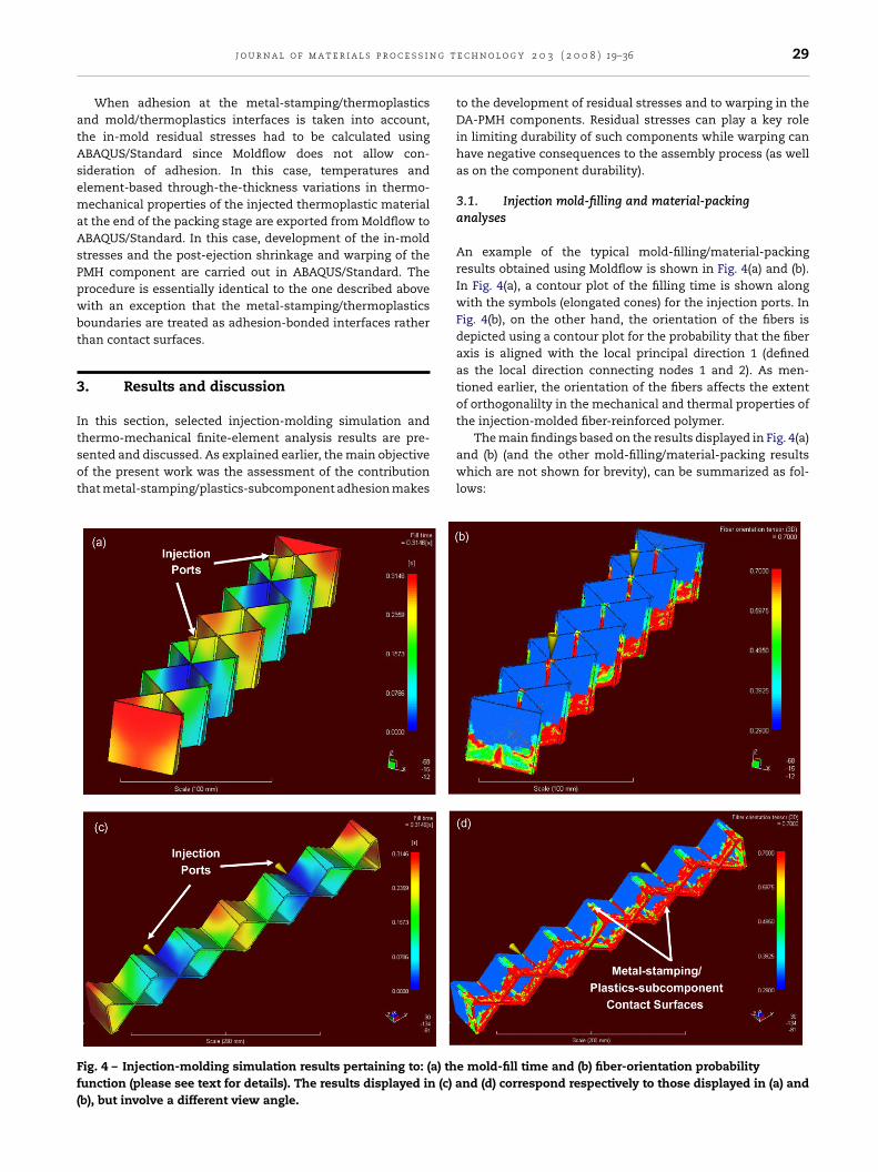
g t
atAsemaAsPpwbt
3
Itsot
Ff(
j o u r n a l o f m a t e r i a l s p r o c e s s i n
When adhesion at the metal-stamping/thermoplasticsnd mold/thermoplastics interfaces is taken into account,he in-mold residual stresses had to be calculated usingBAQUS/Standard since Moldflow does not allow con-ideration of adhesion. In this case, temperatures andlement-based through-the-thickness variations in thermo-echanical properties of the injected thermoplastic material
t the end of the packing stage are exported from Moldflow toBAQUS/Standard. In this case, development of the in-moldtresses and the post-ejection shrinkage and warping of theMH component are carried out in ABAQUS/Standard. Therocedure is essentially identical to the one described aboveith an exception that the metal-stamping/thermoplasticsoundaries are treated as adhesion-bonded interfaces ratherhan contact surfaces.
. Results and discussion
n this section, selected injection-molding simulation and
hermo-mechanical finite-element analysis results are pre-ented and discussed. As explained earlier, the main objectivef the present work was the assessment of the contributionhat metal-stamping/plastics-subcomponent adhesion makesig. 4 – Injection-molding simulation results pertaining to: (a) thunction (please see text for details). The results displayed in (c) ab), but involve a different view angle.
e c h n o l o g y 2 0 3 ( 2 0 0 8 ) 19–36 29
to the development of residual stresses and to warping in theDA-PMH components. Residual stresses can play a key rolein limiting durability of such components while warping canhave negative consequences to the assembly process (as wellas on the component durability).
3.1. Injection mold-filling and material-packinganalyses
An example of the typical mold-filling/material-packingresults obtained using Moldflow is shown in Fig. 4(a) and (b).In Fig. 4(a), a contour plot of the filling time is shown alongwith the symbols (elongated cones) for the injection ports. InFig. 4(b), on the other hand, the orientation of the fibers isdepicted using a contour plot for the probability that the fiberaxis is aligned with the local principal direction 1 (definedas the local direction connecting nodes 1 and 2). As men-tioned earlier, the orientation of the fibers affects the extentof orthogonalilty in the mechanical and thermal properties ofthe injection-molded fiber-reinforced polymer.
The main findings based on the results displayed in Fig. 4(a)and (b) (and the other mold-filling/material-packing resultswhich are not shown for brevity), can be summarized as fol-lows:
e mold-fill time and (b) fiber-orientation probabilitynd (d) correspond respectively to those displayed in (a) and

i n g
(
(
30 j o u r n a l o f m a t e r i a l s p r o c e s s
a) Due to a symmetric placement of the two injection ports,Fig. 4(a), melt-flow is fairly balanced (i.e. the sectionsof the mold which are filled last, are filled at approx-imately the same time). This finding suggests that noportion of the injection-molded plastic subcomponent willbe over-packed and that a fairly uniform distribution ofthe thermoplastics density will be attained minimizing thetendency for post-ejection PMH-component warping;
b) A detailed analysis of the results displayed in Fig. 4(b) andthe results pertaining to the melt-flow directions at theend of the material-packing stage indicates that fibers arefairly well aligned with the local flow direction impartinga large extent of orthotropy to the injection-molded shortglass-fiber reinforced nylon 6; and
(c) A fairly uniform distribution of the temperature within theinjection-molded thermoplastic subcomponent is foundat the end of the packing stage (the results not shown forbrevity). This temperature is, at the most, only few tenthsof a degree lower than the melt temperature. This findingis consistent with the fact that the mold-fill time, Fig. 4(a),is only ca. 0.3 s.
3.2. Thermo-mechanical analysis of residual stressesand warping in direct-adhesion PMH components
As explained earlier, when adhesion at the metal-stamping/plastic-subcomponent contact surfaces is not considered, thein-mold residual stresses may develop as a result of the con-
Fig. 5 – Distribution of the von Mises equivalent stress in the plaadhesion at the metal-stamping/plastics-subcomponent interfac
t e c h n o l o g y 2 0 3 ( 2 0 0 8 ) 19–36
straints imposed by the stamping and the mold onto theplastics subcomponents as it undergoes thermal and solidi-fication shrinkage. Under such conditions, thermoplastic sub-component is free to detach itself from the metal-stamping(and the mold), in the subcomponent through-the-thicknessdirection. When adhesion is present at the metal-stamping/thermoplastic-subcomponent interfaces, thermoplastic isconstrained from freely detaching from the metal-stampingsurface. This provides an additional source of in-mold stresses(and, in turn, of the residual stresses in the PMH compo-nent).
An example of the results obtained in the presentthermo-mechanical analysis which clearly revealed the effectof metal-stamping/thermoplastic-subcomponent adhesion ispresented in Figs. 5–8. The spatial-distribution results for thevon Mises equivalent stress corresponding to the “no-adhesion”case are presented in Fig. 5(a) while their counterparts refer-ring to the case when adhesion is taken into account aredisplayed in Fig. 5(b). The results displayed in Fig. 5(a) and(b) clearly reveal two important consequences arising fromadhesion at the metal-stamping/plastics-subcomponent con-tact surfaces: (a) the overall level of the (residual) von Misesstresses is significantly increased and (b) such stresses aremore localized in the regions of direct contact between the
metal stamping and the plastics subcomponent.A comparison of the maximum principal elastic strainresults obtained in the “no-adhesion” and “adhesion” cases isdisplayed in Fig. 6(a) and (b), respectively. The extent of the
stics subcomponent in the: (a) absence and (b) presence ofe.

j o u r n a l o f m a t e r i a l s p r o c e s s i n g t e c h n o l o g y 2 0 3 ( 2 0 0 8 ) 19–36 31
F in thp pon
esmTsctanastnF
a(itdetasscp
ig. 6 – Distribution of the maximum principal elastic strainresence of adhesion at the metal-stamping/plastics-subcom
lastic strains in the thermoplastic component in the adhe-ion case is clearly significantly higher, particularly in theetal-stamping/plastics-subcomponent interfacial regions.
his finding is consistent with the fact that the plasticsubcomponent is constrained from freely contracting duringooling and solidification and, hence, experiences tensile elas-ic deformations. This point is further reinforced in Fig. 7(a)nd (b) where a comparison is made of the normal zz compo-ent of the elastic strain results obtained in the “no-adhesion”nd “adhesion” cases. The zz component of the strain iselected since it has the same (upward) orientation for allhe elements in the plastics subcomponent. It should beoted that only the plastics subcomponent was displayed inigs. 5–7.
The extent of warpage in the PMH component in the “no-dhesion” and the “adhesion” cases is displayed in Fig. 8(a) andb), respectively. For clarity, only the metal-stamping is shownn the two cases. It should be noted that in order to magnifyhe effect of warping on the component shape, a nodal-isplacement scale factor of 10 is applied. It is clear that thextent of warping (even though relatively small) is higher inhe “adhesion” case, where, thermal and solidification shrink-ge of the plastics subcomponent is transferred to the metal
tamping via metal-stamping/plastics-subcomponent adhe-ion bonding. As discussed earlier, PMH component warpingan have deleterious effects on the assembly process (i.e. somereloading may have to be applied to the component to makee plastics subcomponent in the: (a) absence and (b)ent interface.
if fit) and on the component durability (i.e. a sustained loadingis put into the component contribution to an earlier onset ofdamage and potential failure).
Under the injection-molding process conditions used togenerate the results presented in Figs. 5–8, no evidence ofdecohesion at the metal-stamping/polymer-subcomponentinterfaces was observed. This is exemplified in the x–y plotin Fig. 9(curve A), in which the maximum normal interfacial-displacement discontinuity (at an arbitrarily selected location)never exceeds the critical normal (decohesion initiation) sepa-ration (10 nm). To show that under different injection-moldingprocess conditions, interfacial decohesion may take place,normal interfacial displacement discontinuity results corre-spond to the case of a more aggressive cooling are also shownin Fig. 9(curve B). In this case, it is seen that decohesion hasoccurred and, at the location in question, no load transfer (intension or shear) can take place between the plastics sub-component and the metal stamping. This finding is quitesignificant since faster cooling is attractive due to the result-ing shorter cycle time. The present results show, however,that in an attempt to reduce the cycle time, one may com-promise the integrity of the DA-PMH component by creatingdefective plastics-subcomponent/metal-stamping adhesion-
bonded interfaces.It should be noted that all the thermo-mechanicalcalculations of the in-mold/residual stresses and the PMH-component warpage development were carried out using

32 j o u r n a l o f m a t e r i a l s p r o c e s s i n g t e c h n o l o g y 2 0 3 ( 2 0 0 8 ) 19–36
Fig. 7 – Distribution of the zz-component of the elastic strain in tpresence of adhesion at the metal-stamping/plastics-subcompon
Fig. 8 – A comparison of the extents of warping in themetal-stamping in the: (a) absence and (b) presence ofadhesion at the metal-stamping/plastics-subcomponentinterface.
he plastics subcomponent in the: (a) absence and (b)ent interface.
Abaqus/Standard computer program. It is well-establishedthat such calculations accurately capture the basic behaviorand trends. However, a highly comprehensive analysis (involv-ing over 20,000 injection moldings each with varied processconditions, thickness and material) carried out by MoldflowInc. (Moldflow Plastics Insight, 2006) revealed that the warpagepredictions, based solely on thermo-mechanical computa-tional analyses are sufficiently accurate (within 20%) in onlyabout 15–20% of the cases. To overcome this problem, the so-called CRIMS (Corrected In-mold Residual Stress) technique isimplemented in Moldflow. CRIMS is a hybrid technique whichutilizes measured shrinkage data to correct/improve the in-mold/residual stress and warpage development predictionsmade by the thermo-elastic computational analyses. By com-paring the computational predictions with the experimentallymeasured shrinkages, a set of CRIMS correction functionshas been created and the function coefficients stored in theMoldflow Material Database. When an in-mold/residual stressand warping analysis is carried out using Moldflow, thesecoefficients are used to correct the computational results.This procedure was utilized in our previous work (Grujicic etal., in press) in which no effect of metal-stamping/plastics-subcomponent adhesion was investigated. Unfortunately, in
its present formulation, Moldflow does not allow the inclusionof adhesion effects. Consequently, all the thermo-mechanicalanalyses had to be done outside Moldflow, using AbaqusStandard. Since the CRIMS technique is not implemented in
j o u r n a l o f m a t e r i a l s p r o c e s s i n g t
Fig. 9 – The effect of cooling rate on the onset of adhesionat the metal-stamping/polymer-subcomponent contactsj
AcirabdpDp
tiwntpcoip
4
Bi
1
2
urfaces. The critical value of the interfacial displacementump corresponds to the onset of normal-mode decohesion.
baqus/Standard, the in-mold/residual stress and warpingorrections discussed above cannot be applied. Furthermore,n the absence of the corresponding experimental data, theesults displayed in Fig. 5(a) and (b) should be considered onlys indicators for physical trends and less significance shoulde given to their quantitative nature. Nevertheless, the resultsisplayed in Fig. 5(a) and (b), clearly reveal that adhesion maylay an important role and should be taken into account whenA-PMH components are designed and their manufacturingrocess specified.
Since the direct-adhesion PMH technology is quite new,here is very limited amount of experimental data reportedn the open literature. This fact and the fact that the on-goingork carried out by the authors is of purely computationalature, prevents a direct validation of the results obtained inhe present work. Nevertheless, the results obtained in theresent work are consistent with the general expectations onean have regarding the effect of polymer-to-metal adhesionnto the changes in the magnitude and the distribution of
n-mold and post-ejection residual stresses in DA-PMH com-onents.
. Summary and conclusions
ased on the results obtained in the present work, the follow-ng main summary remarks and conclusions can be drawn:
. Injection-molding simulations are combined with thermo-mechanical finite element analysis to assess the roleof adhesion at the metal-stamping/plastic-subcomponentcoated surfaces in the development of in-mold/residual
stresses and warping in direct-adhesion polymer metalhybrid components.. Adhesion at the metal-stamping/plastic-subcomponentinterfaces is modeled using a cohesive-zone formula-
e c h n o l o g y 2 0 3 ( 2 0 0 8 ) 19–36 33
tion within which a special set of interfacial elements isused whose mechanical constitutive response is definedusing appropriate normal and shear traction vs. interfacial-displacement discontinuity laws.
3. In general, adhesion at the metal-stamping/plastic sub-component interfaces has been found to increase boththe magnitude of residual stresses and the extent ofPMH component warping. Both of these effects can havenegative consequences on the assembly process and thecomponent durability and must be considered when aDA-PMH component is and its manufacturing process aredesigned.
Acknowledgements
The material presented in this paper is based on work con-ducted as a part of the project “Lightweight Engineering:Hybrid Structures: Application of Metal/Polymer Hybrid Mate-rials in Load-bearing Automotive Structures” supported byBMW AG, Munchen, Germany. The authors are indebted to Drs.David Angstadt, Greg Moco and Lonny Thomson for stimulat-ing discussions.
Appendix A. Polymer/metaldecohesion/de-bonding potential and its
The plastics/metal interfaces have been modeled in thepresent work using the “cohesive zone framework” originally pro-posed by Needleman (1987). The cohesive zone is assumedto have a negligible thickness when compared with othercharacteristic lengths of the problem, such as the plastics-wall thickness, the width of metal-stamping grooves, or thecharacteristic lengths associated with the stress/strain gra-dients. The mechanical behavior of the cohesive zone ischaracterized by a traction–displacement relation, which isintroduced through the definition of an interfacial potential, . The perfectly bonded plastic/metal interface is assumedto be in a stable equilibrium, in which case the potential has a minimum and all tractions vanish. For any otherconfiguration, the value of the potential is taken to dependonly on the displacements discontinuities (jumps) across theinterface. To simplify the analysis presented in this sectionand reduce the length of the document, a two-dimensionalcase is treated. The plastics/metal decohesion analysis usedin this paper was, however, a full three-dimensional analy-sis.
For a two-dimensional problem, the interface displace-ment jump (i.e. the interfacial separation) is expressed interms of its normal component, Un, and a tangential com-ponent, Ut, where both components lie in the x–y plane ofthe Cartesian coordinate system. Differentiating the interfacepotential function = (Un, Ut) with respect to Un and Ut
yields respectively, the normal and tangential componentsof F, the traction per unit plastic/metal interface area in the
deformed configuration, asFn(Un, Ut) = −∂ (Un, Ut)∂Un
(A1)

i n g t e c h n o l o g y 2 0 3 ( 2 0 0 8 ) 19–36
Fig. A1 – Normalized normal, Fn, and tangentialcomponents, Ft, of the traction per unit interface area, as a
34 j o u r n a l o f m a t e r i a l s p r o c e s s
Ft(Un, Ut) = −∂ (Un, Ut)∂Ut
(A2)
The interface traction/separation constitutive relations arethus fully defined by specifying the form for the interfacepotential function (Un, Ut). The interface potential of thefollowing form initially proposed by Socrate (1995) is used inthe present study:
(Un, Ut) ={
{−e�maxın + 12�maxıt log
[cosh
(2Ut
ıt
)]}
×[
e−Un/ın
(1 + Un
ın
)](A3)
where the parameters �max and �max are, respectively, thenormal and tangential interfacial (cohesion) strengths, andın and ıt are the corresponding characteristic interface (sepa-ration/sliding) lengths. Differentiation of Eq. (A3) with respectto Un and Ut yields the following expressions for the normaland tangential interfacial tractions:
Fn(Un, Ut) ={e�max − 1
2�max
ıtın
log[
cosh(
2Ut
ıt
)]}
×[Un
ıne−Un/ın
](A4)
Ft(Un, Ut) =[�max tanh
(2Ut
ıt
)][e−Un/ın
(1 + Un
ın
)](A5)
Graphical representations of the two functions defined byEqs. (A4) and (A5) are given in Fig. A1(a) and (b), respectively. IfFn given by Eq. (A4), is expressed for the case of purely normalinterface decohesion, and the Ft for the case of pure sliding,one obtains:
Fn(Un, Ut = 0) = Fon(Un) = e�max
(Un
ıne−(Un/ın)
)(A6)
Ft(Un = 0, Ut) = Fot (Ut) = �max tanh
(2Ut
ıt
)(A7)
An inspection of Eqs. (A6) and (A7) shows that the plas-tics/metal interface behavior is characterized by fourparameters: �max, ın, �max and ıt; where �max is the peaknormal traction for purely normal interface decohesion (i.e.the normal decohesion strength); ın is the normal interfaceseparation which corresponds to this peak traction; �max isan asymptotic shear traction for interface sliding (i.e. theshear decohesion strength); and ıt is a characteristic length inpure sliding, which corresponds to a shear traction 1% lowerthan �max, i.e. Fo
t (ıt) ≈ 0.99 �max. For the case of plastics/metalinterfaces based on BKV 130 H2.0 and steel, these four param-eters were determined in our previous work (Grujicic et al.,submitted for publication-b).
The interface decohesion potential presented above isnext incorporated into a User Element Library (UEL) subrou-tine of Abaqus/Standard. The UEL subroutine allows the user
to define the contribution of the interfacial elements to theglobal finite element model. In other words, for the given nodaldisplacements of the interface elements provided to UEL byABAQUS, the contribution of the elements to the global vectorfunction of the normalized normal, Un, and normalizedtangential, Ut, components of the interface displacements.
of residual forces and to the global Jacobian (element stiff-ness matrix) is computed in the UEL subroutine and passedback to Abaqus/Standard. The implementation of the inter-face decohesion potential in the UEL subroutine is discussedbelow.
For the two-dimensional case presented here, eachinterface element is defined as a four-node iso-parametricelement on the plastics/metal interface, as shown schemati-cally in Fig. A2. In the un-deformed configuration (not shownfor brevity), nodes 1 and 4, and nodes 2 and 3 coincide,respectively. A local co-ordinate system, consistent with thedirections that are tangent, t, and normal, n, to the inter-face, is next assigned to the each element. This is done byintroducing two internal nodes, A and B, located at the mid-points of the lines 1–2 and 3–4, connecting the correspondinginterface nodes of the plastics and the metal. The interfacedisplacements at the internal nodes A and B are expressedin terms of the displacements of the element nodes 1–4 as inthe global coordinate system z–r, as
UAn = (U4
z − U1z ) cos � − (U4
r − U1r ) sin � (A8)
UAt = (U4
z − U1z ) sin � − (U4
r − U1r ) cos � (A9)
UBn = (U3
z − U2z ) cos � − (U3
r − U2r ) sin � (A10)
UBt = (U3
z − U2z ) sin � − (U3
r − U2r ) cos � (A11)

j o u r n a l o f m a t e r i a l s p r o c e s s i n g t
Fig. A2 – Definition of the linear, four-node axisymmetricinterface element. Nodes 1 and 4 and nodes 2 and 3 coincidein the equilibrium (reference) configuration. Internalnodes A and B located at the midpoints of segmentsconnected corresponding nodes in the metal and plasticssa
AtlNtiv
U
U
TAtnt
∫
wfoU
ı
r
ides of the interface; two integration points markeds + and a local t–n co-ordinate system are also indicated.
n iso-parametric coordinate � is next introduced alonghe tangent direction with �(A) = −1 and �(B) = 1 and twoinear Lagrangian interpolation functions are defined as
A(�) = (1 − �)/2 and NB(�) = (1 − �)/2. These interpolation func-ions allow the normal and the tangential components of thenterface displacements to be expressed in the form of theiralues at the internal nodes A and B as
t(�) = NA(�)UAt +NB(�)UB
t (A12)
n(�) = NA(�)UAn +NB(�)UB
n (A13)
he tangential and normal components of the forces at nodesand B, i.e. FA
t , FBt , FA
n and FAn , which are work conjugates of
he corresponding nodal displacements UAt , UB
t , UAn and UB
n areext determined through the application of the virtual worko the interfacial element as
1
−1
ı˚(�)L r(�) d� =∑I=n,t
∑N=A,B
FNI ıU
NI (A14)
here L is the A–B element length. The perturbation of inter-ace potential is next expressed in terms of the perturbationsf the interface displacements at the internal nodes A and B,At , UB
t , UAn , and UB
n as
˚ = ∂˚[Ut(�), Un(�)]∂Un
[NA(�)ıUAn +NB(�)ıUB
n]
+ ∂˚[Ut(�), Un(�)]∂Ut
[NA(�)ıUAt +NB(�)ıUB
t ] (A15)
e c h n o l o g y 2 0 3 ( 2 0 0 8 ) 19–36 35
By substituting Eq. (A15) into Eq. (A14) and by choosing one ofthe ıUNI (N = A,B; I = t,n) perturbations at a time to be unityand the remaining perturbations to be zero, the correspondingFNI component of the nodal force can be expressed as
FNI =∫ 1
−1
∂˚[Ut(�), Un(�)]∂UI
NN(�)L r(�) d� (A16)
Using a straightforward geometrical procedure and imposingthe equilibrium condition, the corresponding residual nodalforces Rir and Riz(i = 1 − 4) in the global r–z co-ordinate system,are defined as
R1r = −R4
r = FAt cos �−FA
n sin �, R1z = −R4
z = FAt sin �−FA
n cos �,
R2r = −R3
r = FBt cos � − FB
n sin �, R2z = −R3
z = FBt sin �−FB
n cos �
(A17)
The components of the interface-element Jacobian are nextdefined as
∂Rij
∂UKI=
∑I=n,t
∑N=A,B
∑j=n,t
∑M=A,B
∂Rij
∂FNI
∂FNI∂UM
j
∂UMj
∂UKI(A18)
where the components of the internal Jacobian ∂FNi/∂UM
j(i, j =
n, t;N,M = A,B) are calculated by differentiation of Eq. (A16).To summarize, the residual nodal forces given by Eqs.
(A17) and the element Jacobian given by Eq. (A18) are com-puted in the UEL subroutine, and passed to Abaqus/Standardfor the use in its global Newton scheme for accurateassessment of the kinematics in the thermo-mechanicalanalysis of residual stress and interfacial decohesion develop-ment during polymer-to-metal direct-adhesion automotive-component manufacturing by injection molding.
e f e r e n c e s
ABAQUS, 2006. Version 6.6. User Documentation. ABAQUS Inc.,Rising Sun Mills, Providence, RI.
Advani, S.G., Tucker III, C.L., 1987. The use of tensors to describeand predict fibers orientation in short fiber composites. J.Rheol. 31, 751–784.
Altan, M.C., GuEceri, S.I., Pipes, R.B., 1992. Anisotropic channelflow of fiber suspensions. J. Non-Newtonian Fluid Mech. 14,65–83.
Bird, R.B., Armstrong, R.C., Hassager, O., 1987. Dynamics ofPolymeric Liquids: Fluid Mechanics, vol. 1., second ed. Wiley,New York.
Bushko, W.C., Stokes, V.K., 1996. Solidification ofthermoviscoelastic melts. Part 4. Effects of boundaryconditions on shrinkage and residual stresses. Polym. Eng.Sci. 36, 658–675.
Camacho, C.W., Tucker III, C.L., Yalvac, S., McGee, R.L., 1990.Stiffness and thermal expansion predictions for hybrid shortfiber composites. Polym. Compos. 11, 229–239.
CATIA, Version V5R16, Dassault Systems. www.3ds.com.
Crochet, M.J., Dupret, F., Verleye, V., 1994. In: Advani, S.G. (Ed.),Flow and Rheology in Polymer Composites Manufacturing,Ch. 11. Elsevier, Amsterdam.
Doi, M., 1981. Molecular dynamics and rheological properties ofconcentrated solutions of rodlike polymers in isotropic and

i n g
36 j o u r n a l o f m a t e r i a l s p r o c e s sliquid crystalline phases. J. Polym. Sci. Polym. Phys. Ed. 19,229–243.
Eduljee, R.F., McCullough, R.L., Gillespie Jr., J.W., 1994. Theinfluence of aggregated and dispersed textures on the elasticproperties of discontinuous-fiber composites. Comp. Sci.Technol. 50, 381–391.
Fan, X.J., Phan-Thien, N., Zheng, R., 1998. A direct simulation offiber suspensions. J. Non-Newtonian Fluid Mech. 74, 113–136.
Ferry, J.D., 1980. Viscoelastic Properties of Polymers, third ed.Wiley, New York.
Folgar, F.P., Tucker, C.L., 1984. Orientation behaviour of fibers inconcentrated suspensions. J. Reinforced Plastics Compos. 3,98–119.
Grujicic, M., Zhao, C.L., Dusel, E.C., 2005. The effect of thermalcontact resistance on heat management in the electronicpackaging. Appl. Surf. Sci. 246, 290–302.
Grujicic, M., Sellappan, V., Arakere, G., Seyr, N., Erdmann, M. (inpress). Computational feasibility analysis of direct-adhesionpolymer-to-metal hybrid technology for load-bearingbody-in-white structural components, J. Mater. Process.Technol., doi:10.1016/j.jmatprotec.2007.05.016.
Grujicic M., Sellappan V., Omar, M.A., Seyr, N., Erdmann, M.(submitted for publication-a). An overview of thepolymer-to-metal direct-adhesion hybrid technologies forload-bearing automotive components. Mater. Process.Technol.
Grujicic, M., Arakere, G., Mears, L., Seyr, N., Erdmann, M.(submitted for publication-b). Application of topology, sizeand shape optimization methods in polymer metal hybridstructural lightweight engineering, Multidiscipline Model.Mater. Struct.
Guell, D., Lovalenti, M., 1995. An examination of assumptionsunderlying the state of the art in injection molding modeling.SPE ANTEC 95 (1), 728–732.
Halpin, J.C., Kardos, J.L., 1976. The Halpin-Tsai equations: areview. Polym. Eng. Sci. 16, 344–352.
Hypermesh, Altair Engineering Inc. www.altair.com.Jeffery, G.B., 1922. The motion of ellipsoidal particles immersed in
viscous fluid. Proc. Roy. Soc. Lond. A 102, 161–179.Lipscomb II, G.G., Denn, M.M., Hur, D.U., Boger, D.V., 1988. The
flow of fiber suspensions in complex geometry. J.Non-Newtonian Fluid Mech. 26, 297–325.
MATLAB, 2006. The Language of Technical Computing, seventh
ed. The MathWorks Inc., MA.Moldflow Plastics Insight, 2006.Version 6.1, User Documentation,Moldflow Corporation, Framingham, MA.
Needleman, A., 1987. A continuum model for void nucleation byinclusion debonding. J. Appl. Mech. 54, 525–531.
t e c h n o l o g y 2 0 3 ( 2 0 0 8 ) 19–36
Papathanasiou, T.D., Guell, D.C. (Eds.), 1997. Flow-inducedAlignment in Composite Materials. Woodhead, Cambridge,UK.
Phan-Thien, N., Graham, A.L., 1991. A new constitutive model forfiber suspensions: flow past a sphere. J. Rheol. 30, 44–57.
Phan-Thien, N., Zheng, R., 1997. Macroscopic modelling of theevolution of fibers orientation during flow. In: Papathanasiou,T.D., Guell, D.C. (Eds.), Flow-Induced Alignment in CompositeMaterials, Ch. 3. Woodhead, Cambridge, UK.
Phan-Thien, N., Zheng, R., Graham, A.L., 1991. The flow of amodel suspension fluid past a sphere. J. Stat. Phys. 62,1173–1195.
Plastic-Metal Hybrid Material. http://www.hbmedia.net/polymotive/polymotive/2003/01/articles/frontend1.shtml.
Recktenwald, D., 2005. Advanced adhesives foster hybridstructures. Mach. Design 77 (21), 124–126.
Rezayat, M., Burton, T.E., 1990. A boundary-integral formulationfor complex three-dimensional geometries. Int. J. Numer.Meth. Eng. 29, 263–273.
Rosenberg, J., Denn, M.M., Keunings, R., 1990. Simulation ofnon-recirculating flows of dilute fiber suspensions. J.Non-Newtonian Fluid Mech. 37, 317–345.
Schapery, R.A., 1968. Thermal expansion coefficients ofcomposite materials based on energy principles. J. Compos.Mater. 2, 380–404.
Socrate, S., 1995. Mechanics of microvoid nucleation and growthin high-strength metastable austenitic steels. PhD Thesis.Massachusetts Institute of Technology.
Tanner, R.I., 1988. Engineering Rheology, second ed. Oxford Press,London.
Tucker III, C.L., 1991. Flow regimes for fiber suspensions innarrow gaps. J. Non-Newtonian Fluid Mech. 39, 239–268.
Yamane, Y., Kaneda, Y., Doi, M., 1994. Numerical simulation ofsemi-dilute suspensions of rodlike particles in shear flow. J.Non-Newtonian Fluid Mech. 54, 405–421.
Zheng, R., 1991. Boundary element methods for some problemsin fluid mechanics and rheology. PhD Thesis. University ofSydney, 1991.
Zheng, R., Kennedy, P., Phan-Thien, N., Fan, X.J., 1999.Thermoviscoelastic simulation of thermally andpressure-induced stresses in injection moldingfor the prediction of shrinkage and warpage forfiber-reinforced thermoplastics. J. Non-Newtonian
Fluid Mech. 84, 159–190.Zoellner, O.J., Evans, J.A., 2002. Plastic-metal hybrid. A newdevelopment in the injection molding technology. In:ANTEC 2002 Annual Technical Conference, San Francisco, CA,pp. 1–4.