computational fluid flow analysis of high speed … · computational fluid flow analysis of high...
TRANSCRIPT

Asian Journal of Engineering and Applied Technology ISSN: 2249-068X Vol. 4 No. 1, 2015, pp.44-52
© The Research Publication, www.trp.org.in
Computational Fluid Flow Analysis of High Speed Cryogenic Turbine Using CFX
Sushant Upadhyay1, Shreya Srivastava2, Siddharth Sagar3, Surabhi Singh4 and Hitesh Dimri5
Department of Mechanical Engineering, JSS Academy of Technical Education, Noida, Uttar Pradesh, India
E-mail: [email protected], 2 [email protected], 3 [email protected],[email protected], [email protected]
Abstract - A turbo expander also referred as an expansion turbine, is a centrifugal or axial flow turbine through which a high pressure gas is expanded to produce work that is often used to drive a compressor. The low pressure exhaust gas from the turbine is at a very low temperature that is 120K or less depending upon the operating conditions. It is widely used as sources of refrigeration in industrial processes and liquefaction of gases such as oxygen, nitrogen, helium, argon and krypton. A cryogenic system needs many components, compressor, heat exchanger, expansion turbine, instrumentation, vacuum vessel etc. At present most of these process plants operate at medium or low pressure due to its inherent advantages. A basic component which is essential for these processes is the turbo expander.
The main aim of this project to attain a minimum temperature and pressure and to study the variation of Mach number and entropy. This is done by computational fluid flow analysis of high speed rotating turbine. This involves with the three dimensional analysis of flow through a radial expansion turbine, using nitrogen as flowing fluid. The work is performed on various modules of Ansys that is BladGen, TurboGrid, CFX-Pre, CFX-Post. Bladegen is used to create the model of turbine using available data of hub, shroud and blade profile. Turbogrid is used to mesh the model. CFX-Pre is used to define the physical parameters of the flow through the Turbo expander. CFX-Post is used for examining and analyzing results. Using these results variation of different thermodynamic properties like Temperature, Pressure, Mach number, entropy etc. inside the turbine can be seen.
Several graphs are plotted showing the variation of pressure, temperature, entropy and Mach number along streamline and span wise to analyze the flow through cryogenic turbine.
Keywords:Radial turbine, Bladegen, Turbogrid, CFX
I. INTRODUCTION
Turbo expanders are high speed rotating devices typically used in cryogenic applications including natural gas, petrochemicals and air separation industries. As high pressure gas is expanded across the turbine to produces cryogenic temperature, the majority of the energy potential in the gas is extracted and transferred through the shaft to run the compressor.
Though nature has provided an abundant supply of gaseous raw materials in the atmosphere (oxygen, nitrogen) and beneath the earth’s crust (natural gas, helium), we need to harness and store them for meaningful use. For large-scale storage, transportation and for low temperature applications liquefaction of the gases is necessary. For producing atmospheric gases like nitrogen, oxygen and argon in large scale, low temperature distillation provides the most economical route. The low temperature required for liquefaction on of common gases can be obtained by several processes.
Compared to the high and medium pressure systems, turbine based plants have the advantage of high thermodynamic efficiency, high reliability and easier integration with other systems. The expansion turbine is the heart of a modern cryogenic refrigeration or separation system. Cryogenic process plants may also use reciprocating expanders in place of turbines.
II. OVERVIEW OF CRYOGENICTURBOEXPANDER
The turboexpander essentially consists of a turbine wheel and a brake compressor mounted on a single shaft, supported by the required number of journal and thrust bearings. These basic components are held in place by an appropriate housing, which also contains the fluid inlet and exit ducts. The basic components are turbine wheel, brake compressor, shaft, nozzle, bearing, diffuser, seals, etc.
44AJEAT Vol. 4 No. 1, Jan - June 2015

Most of the rotors for small and medium sized plants are vertically oriented for easy installation and maintenance. It consists of a shaft with the turbine wheel fitted at one end and the brake compressor at the other. The high-pressure process gas enters the turbine through piping to the cold end housing and, from there, into the nozzle ring. The fluid accelerates through the converging passages of the nozzles. Pressure energy is transformed into kinetic energy, so that reduction in static temperature takes place. The high velocity gas streams impinge on the rotor blades, imparting force to the rotor and creating torque. The nozzles and the rotor blades are so aligned as to eliminate sudden changes in flow direction and consequent loss of energy. The turbine wheel is of radial or mixed flow geometry, i.e. the flow enters the wheel radially and exits axially. The blade passage has a profile of a three dimensional converging duct, changing from purely radial to an axial-tangential direction. Work is extracted as the process gas undergoes expansion with corresponding drop in static temperature.
III. OBJECTIVE OF PRESENT INVESTIGATION
In the technologically advanced countries many industrial gas manufacturers have switched over from the high-pressure Linde and medium pressure reciprocating engine based Claude systems to the modern expansion turbine based, low pressure cycles. Thus in modern
cryogenic plants use turboexpander as one of the most important components.
For the development of computational fluid flow analysis of turbo expander system this project thas been initiated. The objectives include: (i) building computational fluid dynamic knowledge base on cryogenic turboexpanders (ii) construction of a computational fluid flow model and study of its performance.
IV. LITERATURE REVIEW
One of the main components of most cryogenic plants is the expansion turbine or the turboexpander. Since the turboexpander plays the role of the main cold generator, its properties- reliability and working efficiency to a great extent, affect the cost effectiveness parameters of the entire cryogenic plant.
The concept that an expansion turbine might be used in cycle for the liquefaction of gases was first introduced by Lord Rayleigh in a letter to “Nature” dated June 1898. He discussed the use of a turbine instead of a piston expander for the liquefaction of air. In 1898, a British engineer named Edgar C. Thrupppatenteda liquefying machine using an expansion turbine. A simple method sufficient for the design of a high efficiency expansion turbine is outlined by Kun et. al [1-2].
45 AJEAT Vol. 4 No. 1, Jan - June 2015
Computational Fluid Flow Analysis of High Speed Cryogenic Turbine Using CFX
Agahiet. al. [3-4] have explained the design process of the turboexpander utilizing modern technology, such as CFD software, Computer Numerical Control Technology and Holographic Techniques to further improve anal ready impressive turboexpander efficiency performance. Several characteristics values are used for defining significant performance criteria of turbo machines such as turbine velocity ratio, pressure ratio, flow coefficient factor and specific speed [5]. Balje has presented a simplified method for computing the efficiency of radial turbo machines and for calculating their characteristics [6].The concept of specific speed was first introduced for classifying hydraulic machines. Balje [7] introduced this parameter in design of gas turbines and compressors. PhD dissertation of Ghosh [8] explains the detailed summary of technical features and experimental analysis of cryogenic turboexpander. S.K. Ghosh, R.K. Sahoo, S.K. Sarangi in 2005 gave a computational approach to the design of a cryogenic turbine blade profile[9].
V. COMPUTATIONAL FLUID FLOW ANALYSIS
Mainly three steps are involved in computational fluid flow analysis of turboexpander. Bladegen is used to create the model of turbine using available data of hub, shroud and blade profile. Turbogrid is used to mesh the model. CFX-Pre is used to define and specify the simulation settings and physical parameters required to describe the flow through turboexpander at inlet and outlet. CFX-Post is used for examining and analyzing results. The present design procedure is available in literature [8].
VI. BLADEGEN DESIGNING OF THE MODEL
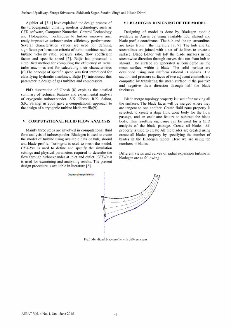
Designing of model is done by Bladegen module available in Ansys by using available hub, shroud and blade profile coordinates. The hub and the tip streamlines are taken from the literature [8, 9]. The hub and tip streamlines are joined with a set of tie lines to create a surface. Blade Editor will loft the blade surfaces in the streamwise direction through curves that run from hub to shroud. The surface so generated is considered as the mean surface within a blade. The solid surface are developed using non uniform rational B splines. The suction and pressure surfaces of two adjacent channels are computed by translating the mean surface in the positive and negative theta direction through half the blade thickness. Blade merge topology property is used after making all the surfaces. The blade faces will be merged where they are tangent to one another. Create fluid zone property is selected, to create a stage fluid zone body for the flow passage, and an enclosure feature to subtract the blade body. This resulting enclosure can be used for a CFD analysis of the blade passage. Create all blades this property is used to create All the blades are created using create all blades property by specifying the number of blades in the Bladegen model. Here we are using ten numbers of blades.
Different views and curves of radial expansion turbine in bladegen are as following.
Fig.1 Meridional blade profile with different spans
46AJEAT Vol. 4 No. 1, Jan - June 2015
Sushant Upadhyay, Shreya Srivastava, Siddharth Sagar, Surabhi Singh and Hitesh Dimri
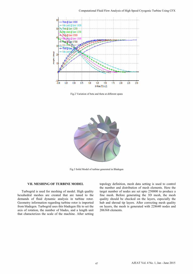
Fig.2 Variation of beta and theta at different spans
Fig.3 Solid Model of turbine generated in Bladegen
VII. MESHING OF TURBINE MODEL
Turbogrid is used for meshing of model. High quality hexahedral meshes are created that are tuned to the demands of fluid dynamic analysis in turbine rotor. Geometry information regarding turbine rotor is imported from bladegen. Turbogrid uses this bladegen file to set the axis of rotation, the number of blades, and a length unit that characterizes the scale of the machine. After setting
topology definition, mesh data setting is used to control the number and distribution of mesh elements. Here the target number of nodes are set upto 250000 to produce a fine mesh. Before generating the 3D mesh, the mesh quality should be checked on the layers, especially the hub and shroud tip layers. After correcting mesh quality on layers, the mesh is generated with 228640 nodes and 206368 elements.
47 AJEAT Vol. 4 No. 1, Jan - June 2015
Computational Fluid Flow Analysis of High Speed Cryogenic Turbine Using CFX
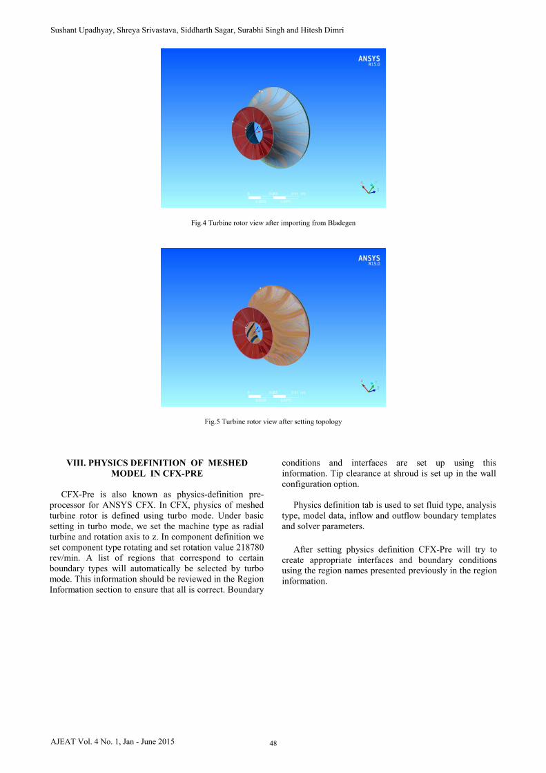
Fig.4 Turbine rotor view after importing from Bladegen
Fig.5 Turbine rotor view after setting topology
VIII. PHYSICS DEFINITION OF MESHED
MODEL IN CFX-PRE
CFX-Pre is also known as physics-definition pre-processor for ANSYS CFX. In CFX, physics of meshed turbine rotor is defined using turbo mode. Under basic setting in turbo mode, we set the machine type as radial turbine and rotation axis to z. In component definition we set component type rotating and set rotation value 218780 rev/min. A list of regions that correspond to certain boundary types will automatically be selected by turbo mode. This information should be reviewed in the Region Information section to ensure that all is correct. Boundary
conditions and interfaces are set up using this information. Tip clearance at shroud is set up in the wall configuration option. Physics definition tab is used to set fluid type, analysis type, model data, inflow and outflow boundary templates and solver parameters.
After setting physics definition CFX-Pre will try to create appropriate interfaces and boundary conditions using the region names presented previously in the region information.
48AJEAT Vol. 4 No. 1, Jan - June 2015
Sushant Upadhyay, Shreya Srivastava, Siddharth Sagar, Surabhi Singh and Hitesh Dimri
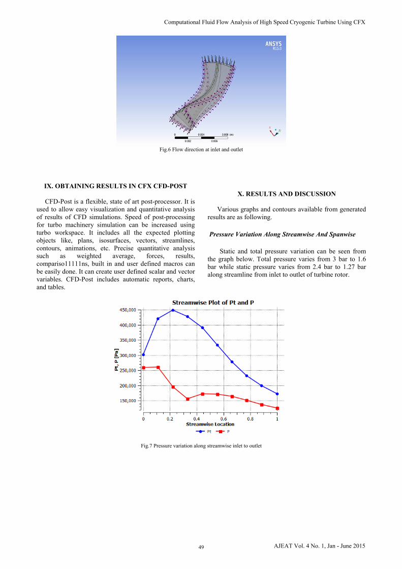
Fig.6 Flow direction at inlet and outlet
IX. OBTAINING RESULTS IN CFX CFD-POST
CFD-Post is a flexible, state of art post-processor. It is used to allow easy visualization and quantitative analysis of results of CFD simulations. Speed of post-processing for turbo machinery simulation can be increased using turbo workspace. It includes all the expected plotting objects like, plans, isosurfaces, vectors, streamlines, contours, animations, etc. Precise quantitative analysis such as weighted average, forces, results, compariso11111ns, built in and user defined macros can be easily done. It can create user defined scalar and vector variables. CFD-Post includes automatic reports, charts, and tables.
X. RESULTS AND DISCUSSION
Various graphs and contours available from generated
results are as following.
Pressure Variation Along Streamwise And Spanwise
Static and total pressure variation can be seen from the graph below. Total pressure varies from 3 bar to 1.6 bar while static pressure varies from 2.4 bar to 1.27 bar along streamline from inlet to outlet of turbine rotor.
Fig.7 Pressure variation along streamwise inlet to outlet
49 AJEAT Vol. 4 No. 1, Jan - June 2015
Computational Fluid Flow Analysis of High Speed Cryogenic Turbine Using CFX
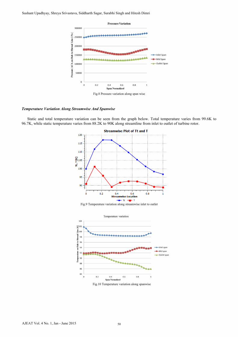
Fig.8 Pressure variation along span wise
Temperature Variation Along Streamwise And Spanwise
Static and total temperature variation can be seen from the graph below. Total temperature varies from 99.6K to
96.7K, while static temperature varies from 88.2K to 90K along streamline from inlet to outlet of turbine rotor.
Fig.9 Temperature variation along streamwise inlet to outlet
Fig.10 Temperature variation along spanwise
50AJEAT Vol. 4 No. 1, Jan - June 2015
Sushant Upadhyay, Shreya Srivastava, Siddharth Sagar, Surabhi Singh and Hitesh Dimri
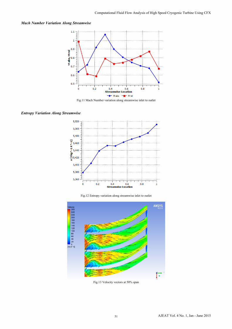
Mach Number Variation Along Streamwise
Fig.11 Mach Number variation along streamwise inlet to outlet
Entropy Variation Along Streamwise
Fig.12 Entropy variation along streamwise inlet to outlet
Fig.13 Velocity vectors at 50% span
51 AJEAT Vol. 4 No. 1, Jan - June 2015
Computational Fluid Flow Analysis of High Speed Cryogenic Turbine Using CFX

XI. CONCLUSION This work is a modest attempt at flow analyzing inside a cryogenic turboexpander through computational fluid dynamic. A prototype expander has been designed, meshed and simulated using this recipe. The design procedure covers the designing of hub, shroud and blade profile of turboexpander in Bladegen. A CFX model has been developed for flow analysis inside the turbine rotor. The modelling of the various parts of the turbine is done in Bladegen and the computational fluid flow analysis is done using CFX. Various graphs and contours indicating the variations of temperature, pressure, velocity inside the turbine along the streamline are given.
REFERENCES
[1] L.C. Kun, T.C. Hanson, High efficiency turboexpander in a N2 liquefier AICHE Spring meeting, Houston, Texas (1985).
[2] L. C. Kun, Expansion turbines and refrigeration for gas separation and liquefaction Advances in Cryogenic Engineering (1987), V33, 963-973
[3] R. R. Aghai, M. C. Lin, B. Ershaghi, High Performance cryogenic turboexpanders Advances in Cryogenic Engineering (1996), V41, 941-947
[4] R. R. Aghai, M. C. Lin, B. Ershaghi, Improvements of the efficiency of the turboexpanders in cryogenic applications Advances in Cryogenic Engineering (1996), V41, 933-940
[5] Von der Nuell , W. T. Single - stage radial turbine for gaseous substances with high rotative and low specific speed Trans ASME (1952), V74, 499-51
[6] O. E. Balje, A contribution to the problem of designing radial turbomachines Trans ASME (1952), V74, 451-472
[7] O. E. Balje, A study on design criteria and matching of turbomachines: Part-A—similarity relations and design criteria of turbines Trans ASME J Eng Power (1972), 83-101
[8] Ghosh, S.k. “Experimental and Computational Studies on Cryogenic Turboexpander” Ph.D dissertation, NIT Rourkela.
[9] Ghosh, S.K., Seshaiah, N., Sahoo, R.K., Sarangi, S.K. Design of Turboexpander for Cryogenic applications, Indian Journal of Cryogenics, Special Issue - Vol.2, 75-81
[10] Dimri, H. “Computaional Fluid Flow Analysis of Cryogenic Turboexpander” M.Tech dissertation, NIT- Rourkela.
52AJEAT Vol. 4 No. 1, Jan - June 2015
Sushant Upadhyay, Shreya Srivastava, Siddharth Sagar, Surabhi Singh and Hitesh Dimri