computationally enhanced construction kits and craft...
TRANSCRIPT
Computationally Enhanced Construction Kits and Craft: Activities during project year 2006/2007
Table of contents
1. Kits and craft projects
a. Number blocks – teaching simple addition
b. e-textile construction kit
c. FlatCAD: design environment for flat things
d. RoBlocks: a Construction Kit for Understanding Emergent Complexity
e. LightLinks: A Computationally-Enhanced Kit for Designing Mechanical Linkages
f. Espresso Blocks
2. Courses taught
a. Things that Think
b. Architectural Robotics
c. Digital Fabrication (how to make things)
3. Workshops
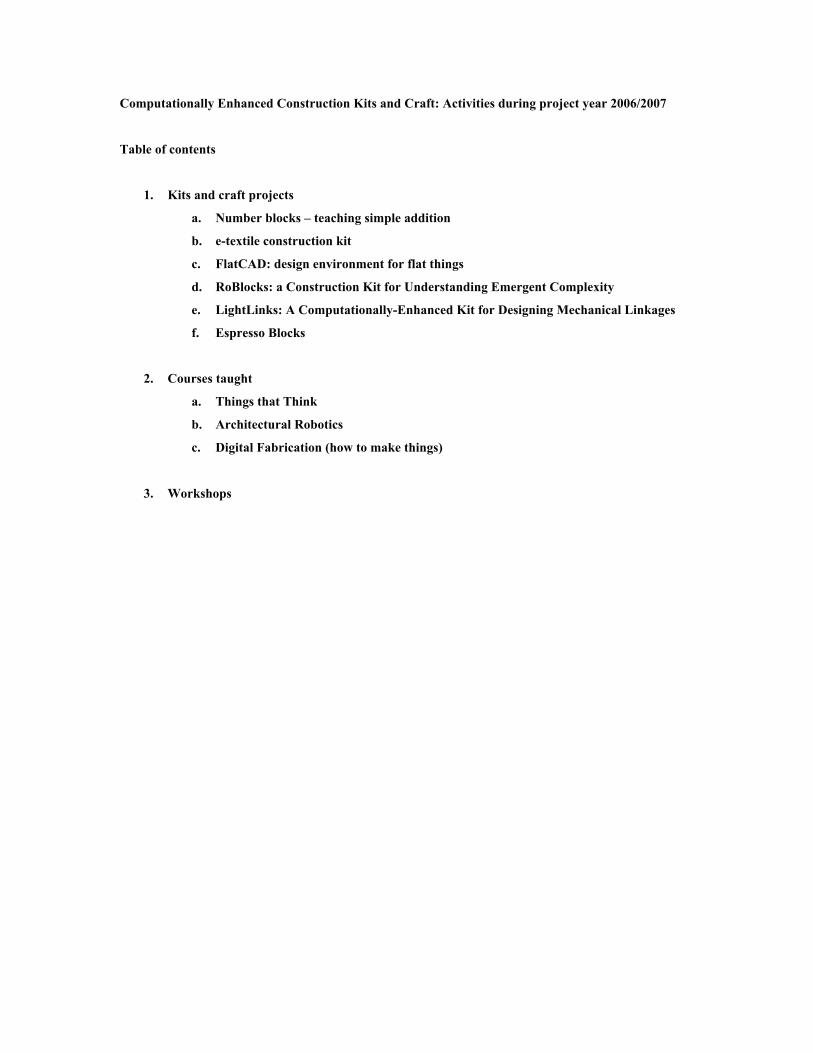
Number Blocks -- Nwanua Elumeze, Ali Crockett, Brad Cooper
Traditionally, children are taught single-digit addition by rote learning and examination. Our intention
in designing our number blocks is to provide a more explorative environment for simple addition. Within
the block environment, children can become familiar with principles of addition independent of the
classroom environment. Each block represents a number between one and nine, and blocks are stacked on
a nine by nine board. When stacks with equivalent sums are built, they will illuminate briefly. Since the
constraint for illumination (namely, equivalence) is not explicitly outlined for the user, it must be derived
from interaction with the blocks. Beyond this basic application, the blocks could also be used for a wide
variety of multiplayer math games; for example, users might be asked to predict illumination, or build
equivalences given a limited set of blocks.
Each block contains a microprocessor, and receives its power from the board, which also contains a
microprocessor. Each time a change occurs in the block configuration, the board turns on stacks in
succession, causing each stack to send its information from the top block downward to the board, building
an array-based representation of the blocks stacked on each of the nine board locations. The board then
compares this representation with previously stored representations to determine if new equivalences are
present, illuminates specific board locations if necessary, and then waits for the next change to repeat the
process.
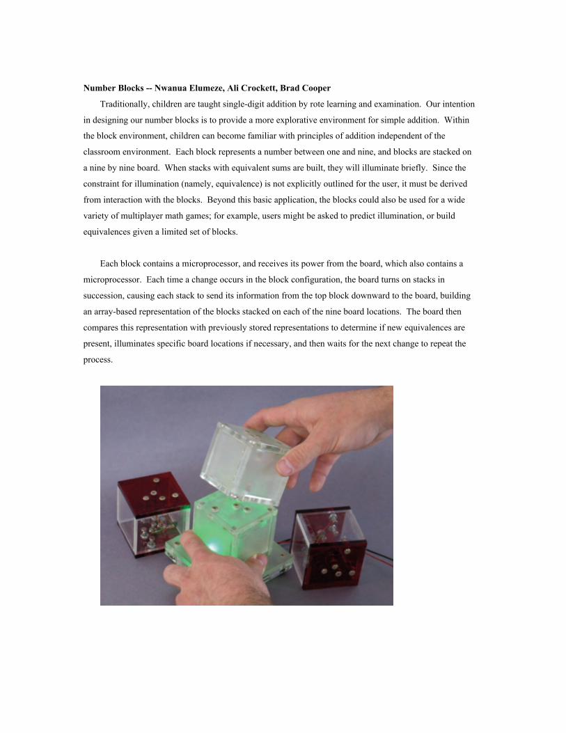
e-textile construction kit -- Leah Buechley
A set of stitch-able controllers, sensors and actuators enables novices to build their own electronic
textiles. The pieces are built using my fabric PCB technique: microcontrollers, sensors and other devices
are soldered to fabric PCBs. The finished pieces can be stitched together with conductive thread into
custom wearables. Users program their constructions using a modified version of the fabulous Arduino
software.
We have held 9 workshops to date, with a total of approximately 80 participants. Each workshop
lasted between 1/2 and 2 hours. Participants ranged in age from 8-adult. Most of the participants
(approximately 87%) were able to complete working designs in the course of a workshop, though for many
of them this was their first introduction to circuits. In general, we have been encouraged by our
experiences in the electronic sewing workshops. Users seem enthusiastic and curious about the activity and
the medium. However, more detailed information is needed before we can draw any conclusions about the
value of these experiences.
the e-textile construction kit contents: stitch-able microcontroller; stitch-able battery holder and 2
CR2032 batteries; velcro on/off switch; needle; conductive thread; LEDs; RGB LED;Beeper; vibrator
motor; light sensor; temperature sensor; fabric switch/pressure sensor; tilt sensor.
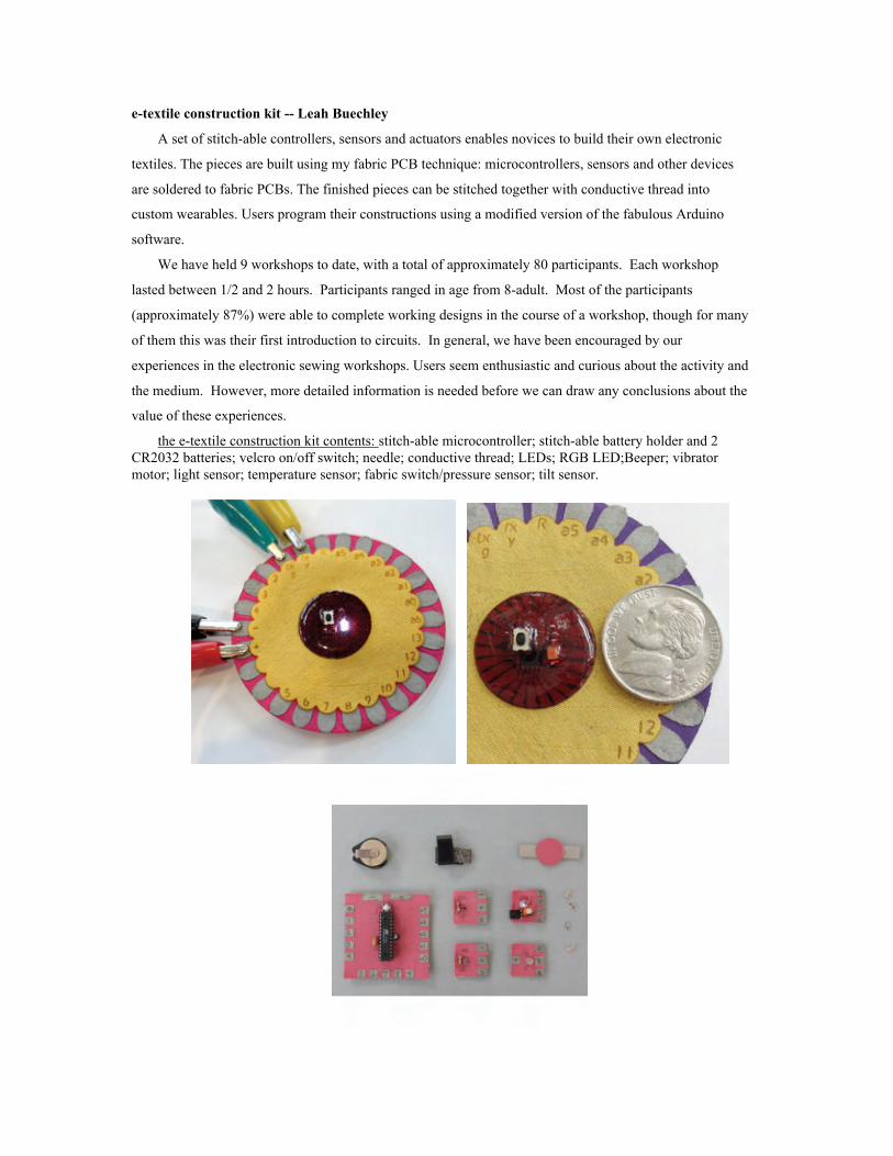
FlatCAD
Gabe Johnson
FlatCAD is a design environment for creating things that can be produced using flat material such as
wood, plastic, or paper on rapid prototyping machines with some acceptable amount of manual assembly
afterwards. For example, one may design a simple box with notched faces or construction kit composed of
a polygons that fit together at right angles with notches (see figure below):
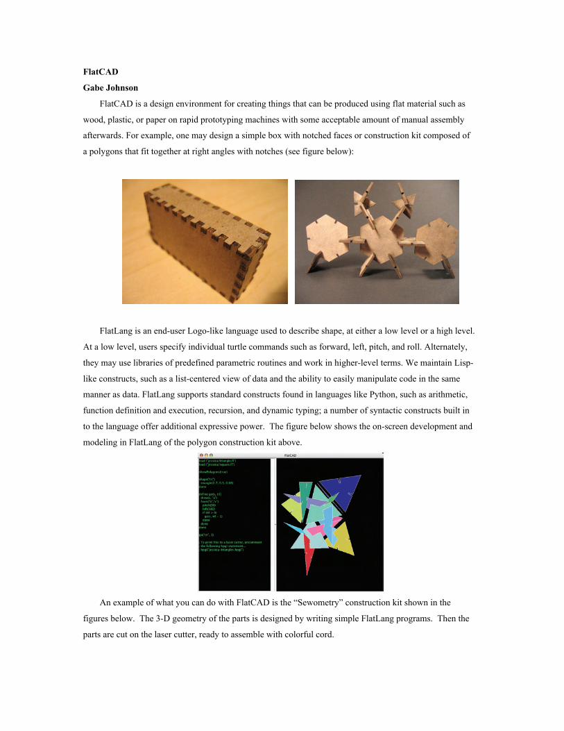
FlatLang is an end-user Logo-like language used to describe shape, at either a low level or a high level.
At a low level, users specify individual turtle commands such as forward, left, pitch, and roll. Alternately,
they may use libraries of predefined parametric routines and work in higher-level terms. We maintain Lisp-
like constructs, such as a list-centered view of data and the ability to easily manipulate code in the same
manner as data. FlatLang supports standard constructs found in languages like Python, such as arithmetic,
function definition and execution, recursion, and dynamic typing; a number of syntactic constructs built in
to the language offer additional expressive power. The figure below shows the on-screen development and
modeling in FlatLang of the polygon construction kit above.
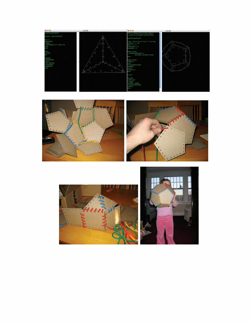
An example of what you can do with FlatCAD is the “Sewometry” construction kit shown in the
figures below. The 3-D geometry of the parts is designed by writing simple FlatLang programs. Then the
parts are cut on the laser cutter, ready to assemble with colorful cord.

roBlocks: a Modular Computational Construction Kit for Understanding Emergent Complexity –
Eric Schweikardt, Mark D Gross
roBlocks are toys for building robots. Children as young as nine snap together the magnetized plastic
cubes and create constructions that drive around on a tabletop, reacting to light and sound. Each roBlock is
different. Some roBlocks add two numbers, some have a multicolored light, some have a little motor and
spin around. Each roBlock contains a tiny computer, and as children build, the computers communicate.
Users program the robot by putting the cubes together. Kids can create robots that follow each other
around, robots that flash their lights along with music, and robots that act as if they are scared of the dark.
The Figure below shows the roBlocks catalog. The first row includes Sensor blocks: blocks that take in
data from the environment. There are sensor blocks for light, touch, sound, motion and distance, and a knob
block that effectively lets a user choose a constant number as input. These sensor blocks act as a robot's
inputs translating conditions around the robot into data that is then passed through the construction.
The second row in the figure includes the Actuator blocks: blocks that do something or perturb the
environment. Several of the actuators contain motors – the Tread block moves around on a tabletop, the
Extension block has a face that pushes out from the others. Also included are a Flashlight block with a
super-bright LED and a Siren block with a small piezoelectric speaker. These actuator blocks act as a
robot's outputs translating its internal data states into actions like movement, sounds and light displays.
The colorful blocks on the third row are Operator blocks. Unlike the Sensor and Actuator blocks,
Operator blocks contain no specialized hardware. Their colors represent their preprogrammed functions –
The catalog of roBlock types: sensors, actuators, operators and utility blocks.
each one operates on the data passed to it in a different way. The yellow block, for instance, takes one or
more inputs from different sensor blocks and passes on the sum of those inputs to any other connected
blocks. Operator blocks let users create simple logical circuits, and when used together, can create a robot
that exhibits surprisingly complex behavior.
The fourth row includes Utility blocks; blocks that neither Sense, Actuate or Operate on data. A Power
block contains two tiny lithium-ion batteries and must be included in each construction as a power source.
The Passive and Blocker blocks may be used as structural elements in a construction with one significant
difference. Passive blocks pass data they receive to their connected neighbors, while Blocker blocks act as
insulators and don't pass data at all. Blocker blocks allow users to create isolated modules and build robots
with functional decomposition. The Comm block contains a Zigbee transceiver for wireless communication
with a host PC. Currently, we use the Comm block for debugging and analysis, but we plan to extend its
capability as an interface element and allow users to reprogram individual blocks.
In a roBlocks construction, each block possesses a single dynamic one-byte value. Sensor blocks
calculate this value from environmental input. A light sensor block, for example, has a value of about 5 in a
dark room, and a value of over 200 outside on a sunny day. A touch sensor has a resting value of zero but
jumps to 255 when it detects contact. Actuator blocks, on the other, hand, actuate according to their value,
which they derive from data passed to them by their neighbors. A Rotation block with a value of zero does
not move, but the same block with a value of 127 would rotate at half speed.
roBlocks pass their values to their connected neighbors. A simple robot made of a single sensor and a
single actuator operates as expected: the actuator operates based on the sensor's input value. Early
prototype sketches acted as a simple data flow network. Sensors acted as sources and actuators as sinks,
and constructions formed an implicit directed graph. This paradigm fails quickly as soon as robots are
constructed that have more than one possible data flow path. The inclusion of more than one sensor in a
roBlocks network creates uncertainty when labeling the graph. Due also to the affordance of assembling
roBlocks in a lattice structure, users often create cyclic constructions which require a better algorithm in
order to exhibit reasonable behavior.
The parallel algorithm for passing data between blocks and calculating block values has been a
significant contribution of our work on roBlocks so far. The blocks operate asynchronously, transferring
data with no central clock. Each block's value is determined by the number of steps from each data source
in a weighted average. With two sensor blocks at either end of a chain of blocks, for example, a gradient of
block values is created, with blocks closer to a high sensor reading exhibiting higher values. This weighted
averaging scheme allows users to create densely packed 3D data structures from a set of blocks and predict
the value at any given point.
We have built a working prototype set of roBlocks. They are made in our laboratory and painstakingly
hand-assembled. We have constructed two sensor blocks (light and knob), three operator blocks (inverse,
sum and minimum), three actuator blocks (tread, number and bar-graph) and several utility blocks (passive,
blocker, power and comm). This small set of blocks is obviously limited in functionality but has been met
with a significant amount of interest and excitement. We have not conducted any formal evaluations with
the current kit, but every person that has seen the blocks has been enthralled and reluctant to put them
down.
Hardware Description
Each roBlock is a 40mm ABS plastic cube, made of two identical three-face halves that screw together
enclosing the electronics inside. The bodies are made on our 3D printer and are built with different colors
of plastic depending on the type of block. Each face of the blocks is identical, and the hermaphroditic
connectors allow each block to connect to any other block at any of its four possible orientations.
Embedded neodymium magnets on each connector provide both physical and electrical connectivity
between blocks. The magnets are strong enough to hold up to eight blocks cantilevered in a single row. On
the back of each connector, the magnets attach with conductive epoxy to the circuit boards shown below.
There are three different circuit boards in each roBlock: one motherboard, one secondary and four passive
boards. The passive and secondary boards hold no major electronics, they simply act as connections
between the magnets on the connectors and the rest of the circuitry. A roBlock is made of two plastic
halves – one half holds the motherboard and two passive boards, and the other half, the secondary and two
passive boards. The two halves are connected with a ribbon cable when they are assembled.
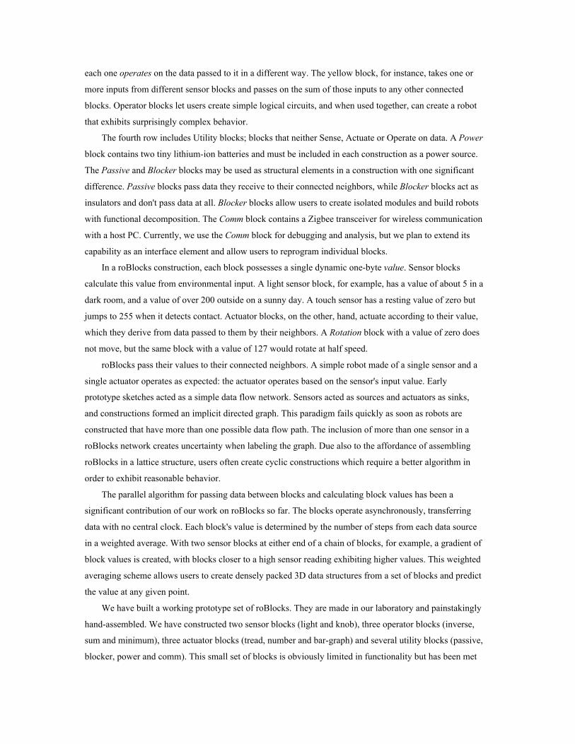
The centerpiece of the motherboard is an Atmel AVR AtMega168 microcontroller. It can be
reprogrammed in place via an in-system-programming header. A second, larger header is included to attach
the various sensors and actuators that each block requires so that a uniform motherboard can be used in all
the roBlocks. Power circuitry, LEDs and other basic electronics also occupy the motherboard. To date, we
have had the circuit boards made for us, but then assembled them by hand. All the components we specify
are surface mount to save space and maintain a single smooth board face that the magnets can be epoxied
to.
Three example robots
Here are three easily constructed little robots.
Interior of an Operator roBlock
The motor and gear mechanisminside a Tread roBlock
A B
C
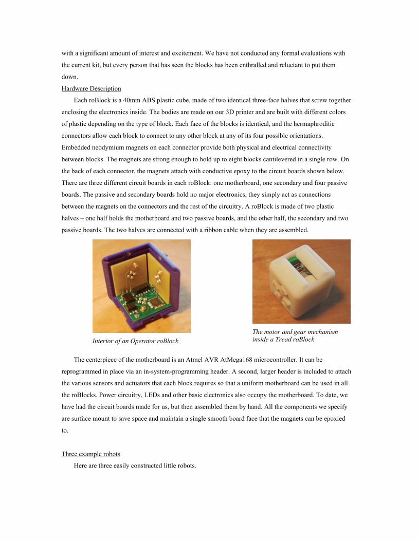
Three example roBlocks robots. A: Threshold, B: Photophobic, C: Curious+.
Robot A is built with five roBlocks: two sensor blocks (Light and Knob), a Maximum operator block,
an actuator block and an obligatory power block. The network and data flow diagram of this robot is Y-
shaped, with the two sensor inputs merging at the operator block and getting passed to the actuator. Any
two sensors could be used here – due to the Maximum block, the actuator function will correspond to the
highest of the two sensor values. As we've chosen a Knob as one of our sensors, the user can set its data
value manually. With this combination, we've created a sort of Threshold robot, in which the value of the
light sensor is taken into account only if it becomes greater than the value of the Knob sensor. Braitenberg
describes how a simple threshold device can be a key element in creating lifelike, emergent behaviors.
Robot B is also built with only five blocks: two Light sensor blocks, two Tread actuator blocks and a
power block. Each actuator is connected most directly to one of the sensors, so will respond more
powerfully whenever the sensor is activated more powerfully. With two Tread blocks, we create a
differential drive robot that turns away from a stimulus, appearing to exhibit the intention of avoiding light.
It has been shown that children as young as six can make the transition from ascribing intent to a robot to
understanding how its instructions could exhibit an intentional-appearing behavior.
Robot C uses seventeen blocks but it only appears complicated as its design is modular. Some blocks
don't have a programmatic role in the robot's behavior, they serve a structural purpose: to keep the robot
balanced. The robot's three modules are connected by Blocker blocks so they function independently. One
module on the front comprises a Light sensor block, an Inverse operator block, and a Flashlight actuator; it
turns on the robot's headlight when it is dark. Each of two identical drive modules is made up of a Motion
sensor, an Inverse operator block and a Tread actuator. Each of these modules independently moves less
whenever it notices something moving. With these two modules assembled side-by-side, we create a robot
that drives along a tabletop until it senses something (perhaps another robot) moving. Our robot then slows
and turns toward the moving object, stopping and twitching when it gets close. If the object stops moving,
our robot continues on its way. A passerby might imagine that that our robot is curious about moving
objects, and perhaps even that it can't see in the dark (which is false). A young user will learn that it is just
exhibiting the complexity arising from the interaction between its component blocks. The user will also
understand that motion sensors work just fine in the dark, that the headlight was simply added for fun, and
will be less likely to attribute causality to erroneous biologically-based assumptions.
LightLinks: A Computationally-Enhanced Kit for Designing Mechanical Linkages
Eric Eason, Mike Eisenberg
The LightLinks project, initiated this past academic year, represents a blend of two distinct means of
computational enhancement for construction kits. On the one hand, LightLinks includes user-designed and
-printed pieces (in acrylic) that can be assembled to create an endless variety of customized mechanical
linkages. On the other hand, once working linkages are created by the user, their movement can be
interpreted and classified by a desktop computer (this aspect of the kit will be explained shortly). Thus,
LightLinks allows users both to create new pieces via computer, and to have overall constructions analyzed
via computer.
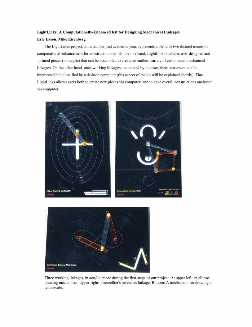
Three working linkages, in acrylic, made during the first stage of our project. At upper left, an ellipse-
drawing mechanism. Upper right: Peaucellier's inversion linkage. Bottom: A mechanism for drawing a
lemniscate.
The inspiration for LightLinks arose from a variety of mechanical linkage displays on view at the
Deutsches Museum in Munich, Germany. These beautiful displays, fashioned in metal, allow museum
visitors to operate linkages by hand and watch the mathematical curves produced by designated points on
the moving pieces. The first, preparatory stage in working on LightLinks, then, was simply to design
several working linkages in acrylic. During this stage, we used the laser cutter in our laboratory both to
make the mechanical elements and to etch designs and text into the background platforms on which the
linkages were placed. Three working display linkages from this stage are shown in the figure above. At
upper left, an ellipse-drawing mechanism is directly based on a similar display from the Deutsches
Museum; at upper right, an elaborate display showing Peaucellier's linkage to produce inversion in a circle;
and at bottom, a mechanism to draw a lemniscate (a figure-eight-like curve). The purpose of this early stage
was to gain familiarity with the craft of linkage-building and to assess the appropriateness of acrylic as a
material for our design.
From Museum-Like Displays to Active Construction
The linkages produced during this early phase are in fact quite robust and attractive (they have been
displayed for public viewing outside our laboratory, and actively played with by visitors to the building, for
at least several months). The purpose of the LightLinks kit is to go well beyond the mere construction of
exhibits, however. In the second phase of the project, we worked on designing a set of pieces that could be
assembled against a general-purpose background to explore a wide range of potential linkages. The
resulting construction kit is shown in the figure below. The major components of the kit are:
a. A background platform, in clear acrylic, in which holes are arranged in a regular lattice. The
platform will be the surface on which new linkages are constructed. (It is possible to create different types
of platforms to support different genres of linkage models. One platform that we have created has holes in a
square lattice, another has holes in a triangular lattice.)
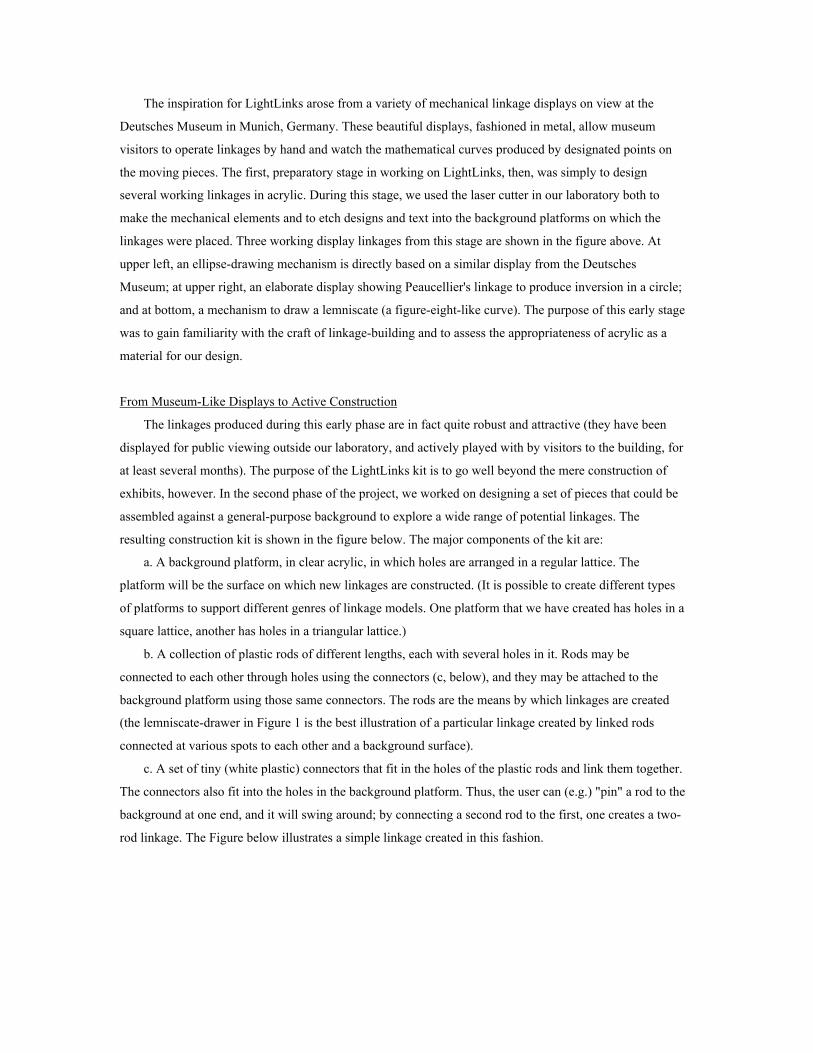
b. A collection of plastic rods of different lengths, each with several holes in it. Rods may be
connected to each other through holes using the connectors (c, below), and they may be attached to the
background platform using those same connectors. The rods are the means by which linkages are created
(the lemniscate-drawer in Figure 1 is the best illustration of a particular linkage created by linked rods
connected at various spots to each other and a background surface).
c. A set of tiny (white plastic) connectors that fit in the holes of the plastic rods and link them together.
The connectors also fit into the holes in the background platform. Thus, the user can (e.g.) "pin" a rod to the
background at one end, and it will swing around; by connecting a second rod to the first, one creates a two-
rod linkage. The Figure below illustrates a simple linkage created in this fashion.
A construction kit for mechanical linkages. At top: a set of pieces used to create linkages. Two
disconnected halves of a clear acrylic "rod" piece are seen at the upper part of the picture, as well as a
few loose plastic white connectors. In the middle of the picture, two rod halves have been joined to
form a rod of a desired length (the design of the rods allows the user to choose among several distinct
lengths for the joined piece). At the bottom of the picture, connectors have been inserted in two holes
(in this case, the end holes) of the rod. The background platform is not shown here; it appears in the
Figure below.
Interpreting Linkage Motion by Computer
The pieces described above constitute the basic elements of a kit that can be used to construct an
endless variety of linkages; but, as is often the case with construction kits, a student may very well create
an interesting linkage without knowing that she has done so. For example, if the student has never heard of
a "lemniscate", she might construct a linkage similar to the one shown in the first Figure without being
aware that there is something worth attending to here.
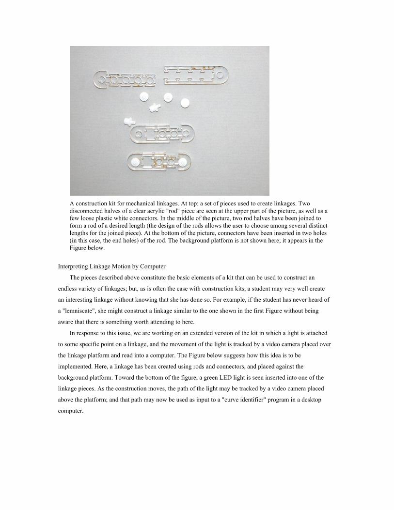
In response to this issue, we are working on an extended version of the kit in which a light is attached
to some specific point on a linkage, and the movement of the light is tracked by a video camera placed over
the linkage platform and read into a computer. The Figure below suggests how this idea is to be
implemented. Here, a linkage has been created using rods and connectors, and placed against the
background platform. Toward the bottom of the figure, a green LED light is seen inserted into one of the
linkage pieces. As the construction moves, the path of the light may be tracked by a video camera placed
above the platform; and that path may now be used as input to a "curve identifier" program in a desktop
computer.
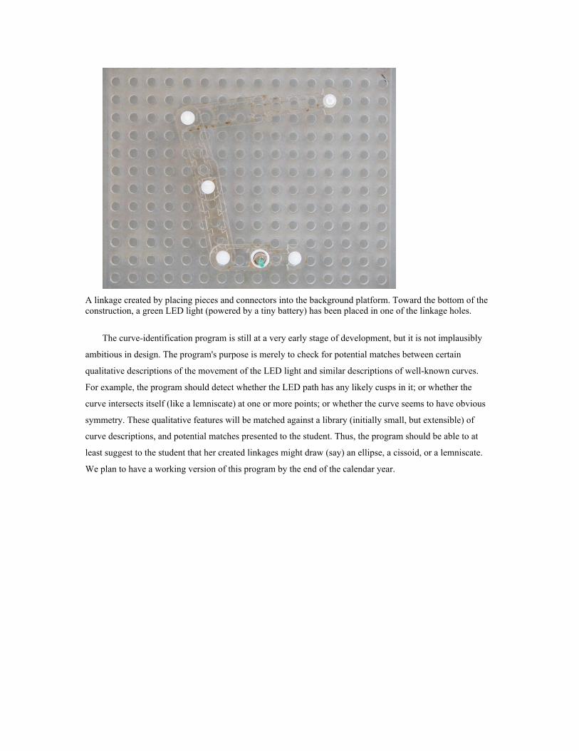
A linkage created by placing pieces and connectors into the background platform. Toward the bottom of the
construction, a green LED light (powered by a tiny battery) has been placed in one of the linkage holes.
The curve-identification program is still at a very early stage of development, but it is not implausibly
ambitious in design. The program's purpose is merely to check for potential matches between certain
qualitative descriptions of the movement of the LED light and similar descriptions of well-known curves.
For example, the program should detect whether the LED path has any likely cusps in it; or whether the
curve intersects itself (like a lemniscate) at one or more points; or whether the curve seems to have obvious
symmetry. These qualitative features will be matched against a library (initially small, but extensible) of
curve descriptions, and potential matches presented to the student. Thus, the program should be able to at
least suggest to the student that her created linkages might draw (say) an ellipse, a cissoid, or a lemniscate.
We plan to have a working version of this program by the end of the calendar year.
Posey: a Poseable Hub and Strut Construction Kit for Undirected Play
Mike Weller and Mark D Gross
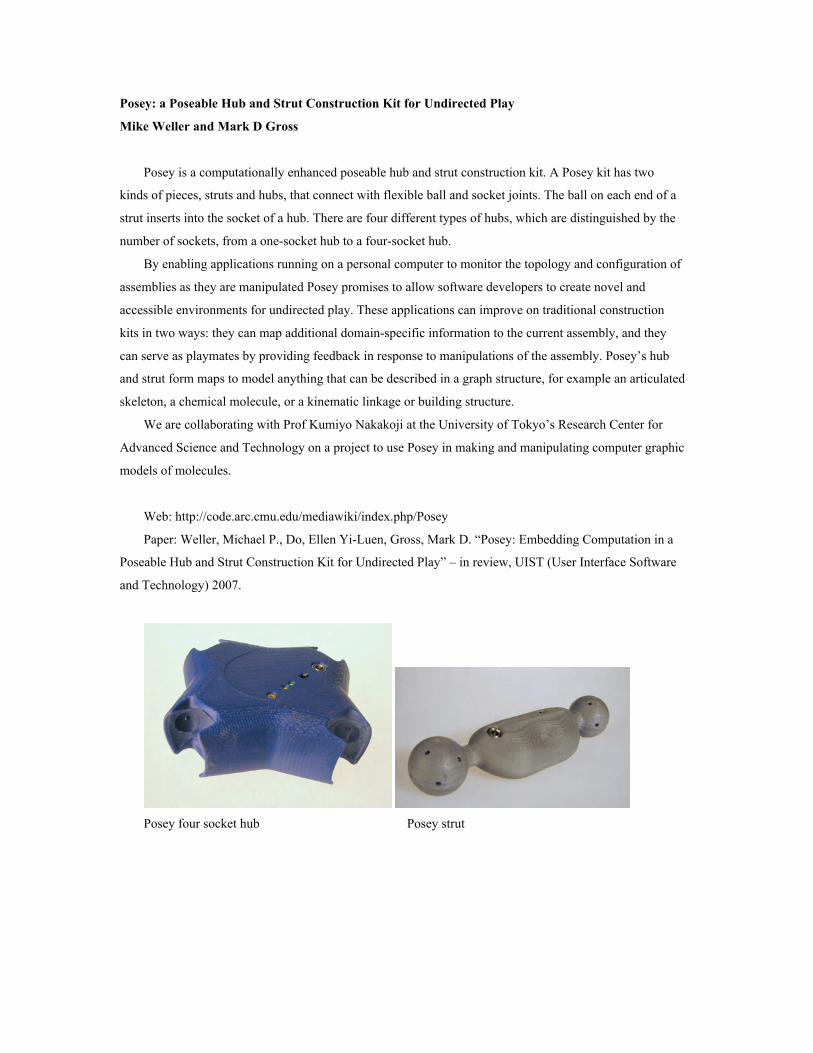
Posey is a computationally enhanced poseable hub and strut construction kit. A Posey kit has two
kinds of pieces, struts and hubs, that connect with flexible ball and socket joints. The ball on each end of a
strut inserts into the socket of a hub. There are four different types of hubs, which are distinguished by the
number of sockets, from a one-socket hub to a four-socket hub.
By enabling applications running on a personal computer to monitor the topology and configuration of
assemblies as they are manipulated Posey promises to allow software developers to create novel and
accessible environments for undirected play. These applications can improve on traditional construction
kits in two ways: they can map additional domain-specific information to the current assembly, and they
can serve as playmates by providing feedback in response to manipulations of the assembly. Posey’s hub
and strut form maps to model anything that can be described in a graph structure, for example an articulated
skeleton, a chemical molecule, or a kinematic linkage or building structure.
We are collaborating with Prof Kumiyo Nakakoji at the University of Tokyo’s Research Center for
Advanced Science and Technology on a project to use Posey in making and manipulating computer graphic
models of molecules.
Web: http://code.arc.cmu.edu/mediawiki/index.php/Posey
Paper: Weller, Michael P., Do, Ellen Yi-Luen, Gross, Mark D. “Posey: Embedding Computation in a
Poseable Hub and Strut Construction Kit for Undirected Play” – in review, UIST (User Interface Software
and Technology) 2007.
Posey four socket hub Posey strut
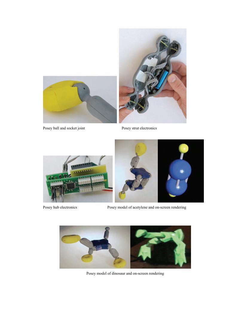
Posey ball and socket joint Posey strut electronics
Posey hub electronics Posey model of acetylene and on-screen rendering
Posey model of dinosaur and on-screen rendering

Espresso Blocks
Mike Weller and Mark D Gross, with Seth Goldstein, Brian Kirby and Emre Karagozler
Web: http://code.arc.cmu.edu/mediawiki/index.php/Espresso_Blocks
We are collaborating with researchers at CMU’s Claytronics Group and Intel Research Pittsburgh to
develop a small prototype reconfigurable building block module and an interface to edit the ruleset
controlling the behavior of the group of blocks to allow children to explore the design space of these cube
robots. The advances this year to date pertain to the redesign of the mating surface latching mechanism,
using electrostatics to connect and disconnect mating surfaces as shown in the figure below.
Left: one cube robot with mating surfaces retracted.
Right: how surfaces mate (top photo; bottom schematic)
Courses offered 2006/2007
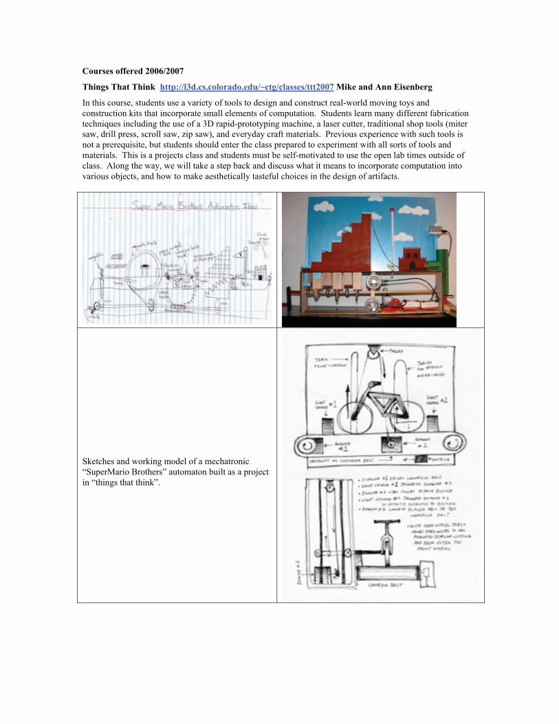
Things That Think http://l3d.cs.colorado.edu/~ctg/classes/ttt2007 Mike and Ann Eisenberg
In this course, students use a variety of tools to design and construct real-world moving toys and
construction kits that incorporate small elements of computation. Students learn many different fabrication
techniques including the use of a 3D rapid-prototyping machine, a laser cutter, traditional shop tools (miter
saw, drill press, scroll saw, zip saw), and everyday craft materials. Previous experience with such tools is
not a prerequisite, but students should enter the class prepared to experiment with all sorts of tools and
materials. This is a projects class and students must be self-motivated to use the open lab times outside of
class. Along the way, we will take a step back and discuss what it means to incorporate computation into
various objects, and how to make aesthetically tasteful choices in the design of artifacts.
Sketches and working model of a mechatronic
“SuperMario Brothers” automaton built as a project
in “things that think”.
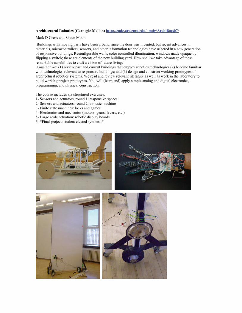
Architectural Robotics (Carnegie Mellon) http://code.arc.cmu.edu/~mdg/ArchiBots07/
Mark D Gross and Shaun Moon
Buildings with moving parts have been around since the door was invented, but recent advances in
materials, microcontrollers, sensors, and other information technologies have ushered in a new generation
of responsive buildings. Reconfigurable walls, color controlled illumination, windows made opaque by
flipping a switch; these are elements of the new building yard. How shall we take advantage of these
remarkable capabilities to craft a vision of future living?
Together we: (1) review past and current buildings that employ robotics technologies (2) become familiar
with technologies relevant to responsive buildings; and (3) design and construct working prototypes of
architectural robotics systems. We read and review relevant literature as well as work in the laboratory to
build working project prototypes. You will (learn and) apply simple analog and digital electronics,
programming, and physical construction.
The course includes six structured exercises:
1- Sensors and actuators, round 1: responsive spaces
2- Sensors and actuators, round 2: a music machine
3- Finite state machines: locks and games
4- Electronics and mechanics (motors, gears, levers, etc.)
5- Large scale actuation: robotic display boards
6- *Final project: student elected synthesis*
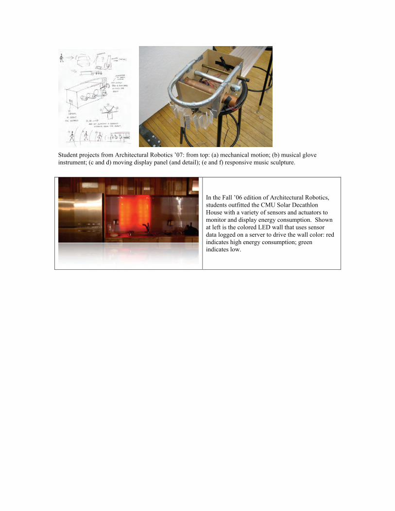
Student projects from Architectural Robotics ’07: from top: (a) mechanical motion; (b) musical glove
instrument; (c and d) moving display panel (and detail); (e and f) responsive music sculpture.
In the Fall ’06 edition of Architectural Robotics,
students outfitted the CMU Solar Decathlon
House with a variety of sensors and actuators to
monitor and display energy consumption. Shown
at left is the colored LED wall that uses sensor
data logged on a server to drive the wall color: red
indicates high energy consumption; green
indicates low.
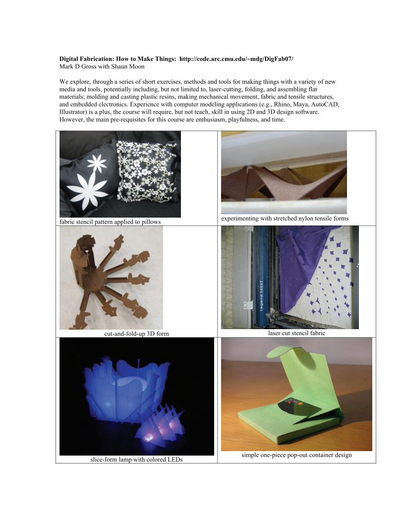
Digital Fabrication: How to Make Things: http://code.arc.cmu.edu/~mdg/DigFab07/
Mark D Gross with Shaun Moon
We explore, through a series of short exercises, methods and tools for making things with a variety of new
media and tools, potentially including, but not limited to, laser-cutting, folding, and assembling flat
materials; molding and casting plastic resins, making mechanical movement, fabric and tensile structures,
and embedded electronics. Experience with computer modeling applications (e.g., Rhino, Maya, AutoCAD,
Illustrator) is a plus, the course will require, but not teach, skill in using 2D and 3D design software.
However, the main pre-requisites for this course are enthusiasm, playfulness, and time.
fabric stencil pattern applied to pillowsexperimenting with stretched nylon tensile forms
cut-and-fold-up 3D form laser cut stencil fabric
slice-form lamp with colored LEDssimple one-piece pop-out container design
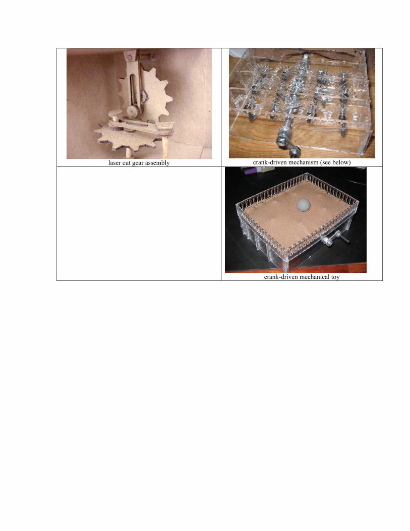
laser cut gear assembly crank-driven mechanism (see below)
crank-driven mechanical toy
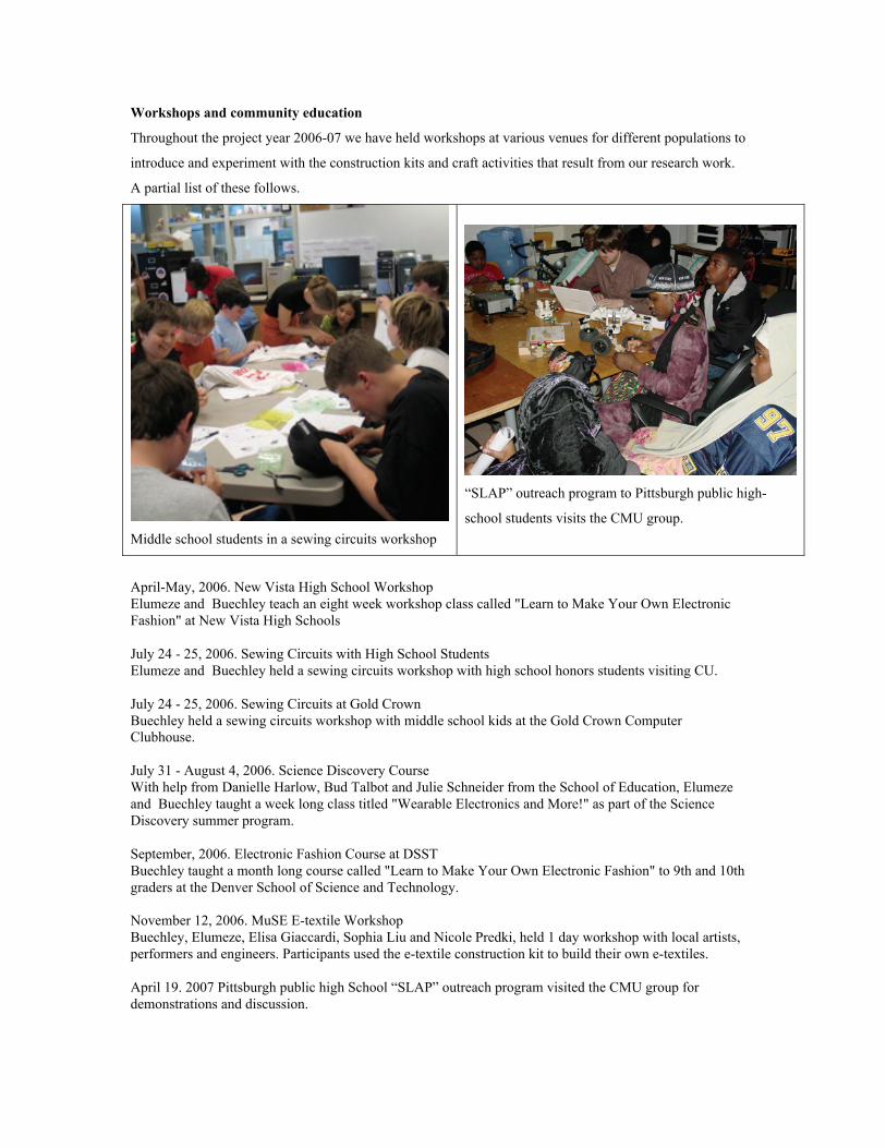
Workshops and community education
Throughout the project year 2006-07 we have held workshops at various venues for different populations to
introduce and experiment with the construction kits and craft activities that result from our research work.
A partial list of these follows.
Middle school students in a sewing circuits workshop
“SLAP” outreach program to Pittsburgh public high-
school students visits the CMU group.
April-May, 2006. New Vista High School Workshop
Elumeze and Buechley teach an eight week workshop class called "Learn to Make Your Own Electronic
Fashion" at New Vista High Schools
July 24 - 25, 2006. Sewing Circuits with High School Students
Elumeze and Buechley held a sewing circuits workshop with high school honors students visiting CU.
July 24 - 25, 2006. Sewing Circuits at Gold Crown
Buechley held a sewing circuits workshop with middle school kids at the Gold Crown Computer
Clubhouse.
July 31 - August 4, 2006. Science Discovery Course
With help from Danielle Harlow, Bud Talbot and Julie Schneider from the School of Education, Elumeze
and Buechley taught a week long class titled "Wearable Electronics and More!" as part of the Science
Discovery summer program.
September, 2006. Electronic Fashion Course at DSST
Buechley taught a month long course called "Learn to Make Your Own Electronic Fashion" to 9th and 10th
graders at the Denver School of Science and Technology.
November 12, 2006. MuSE E-textile Workshop
Buechley, Elumeze, Elisa Giaccardi, Sophia Liu and Nicole Predki, held 1 day workshop with local artists,
performers and engineers. Participants used the e-textile construction kit to build their own e-textiles.
April 19. 2007 Pittsburgh public high School “SLAP” outreach program visited the CMU group for
demonstrations and discussion.

Previous year’s Activities PDF pictures
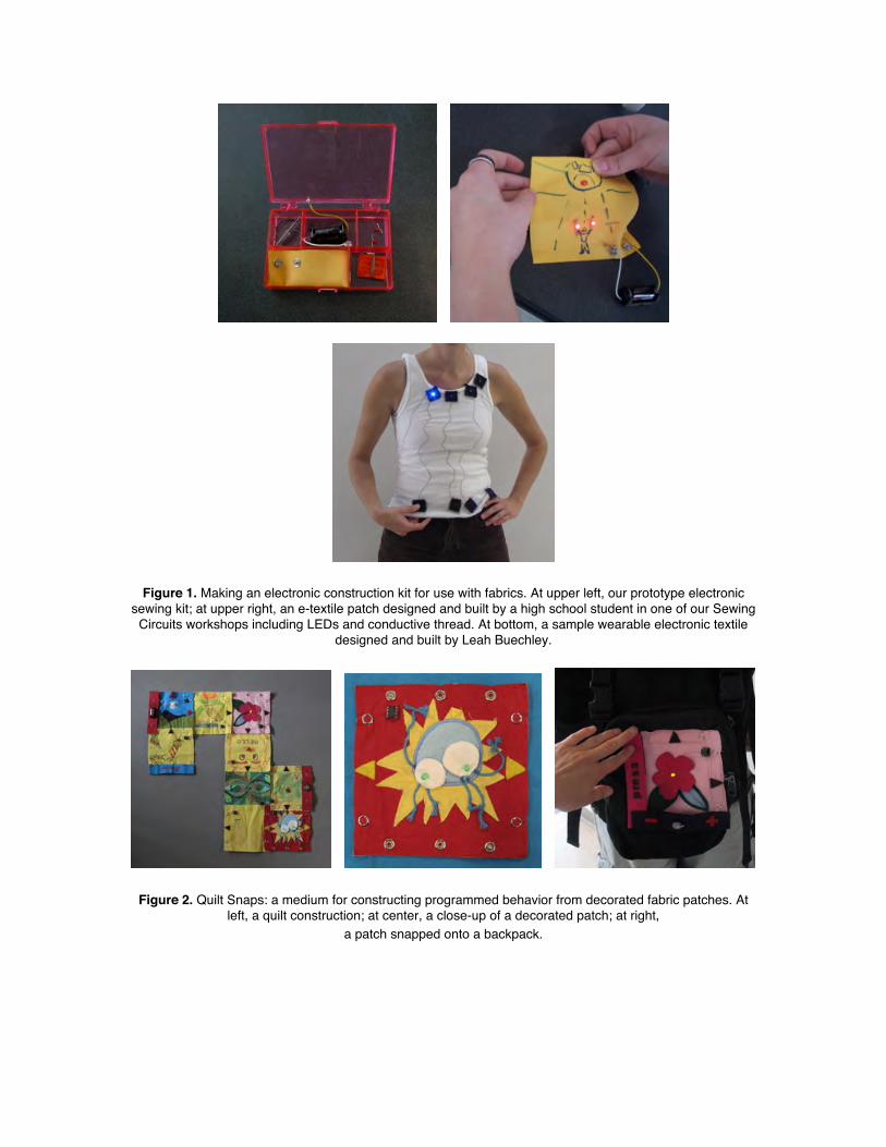
Figure 1. Making an electronic construction kit for use with fabrics. At upper left, our prototype electronicsewing kit; at upper right, an e-textile patch designed and built by a high school student in one of our Sewing
Circuits workshops including LEDs and conductive thread. At bottom, a sample wearable electronic textiledesigned and built by Leah Buechley.
Figure 2. Quilt Snaps: a medium for constructing programmed behavior from decorated fabric patches. Atleft, a quilt construction; at center, a close-up of a decorated patch; at right,
a patch snapped onto a backpack.
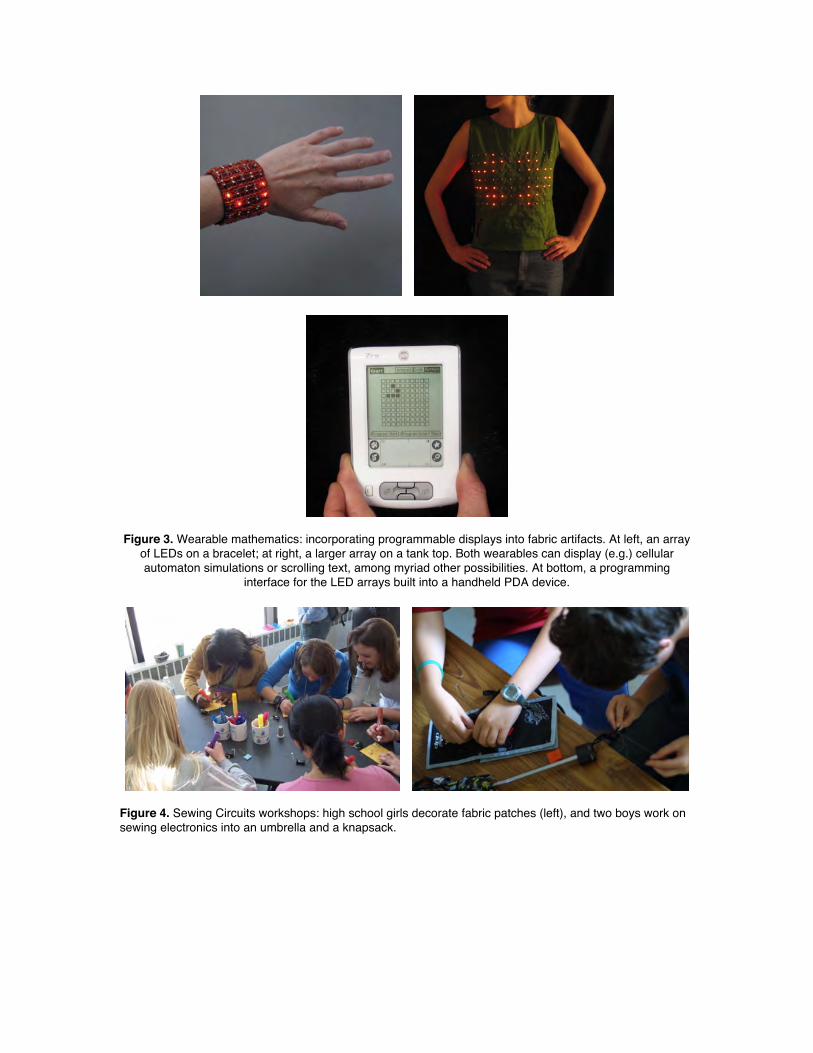
Figure 3. Wearable mathematics: incorporating programmable displays into fabric artifacts. At left, an arrayof LEDs on a bracelet; at right, a larger array on a tank top. Both wearables can display (e.g.) cellularautomaton simulations or scrolling text, among myriad other possibilities. At bottom, a programming
interface for the LED arrays built into a handheld PDA device.
Figure 4. Sewing Circuits workshops: high school girls decorate fabric patches (left), and two boys work onsewing electronics into an umbrella and a knapsack.
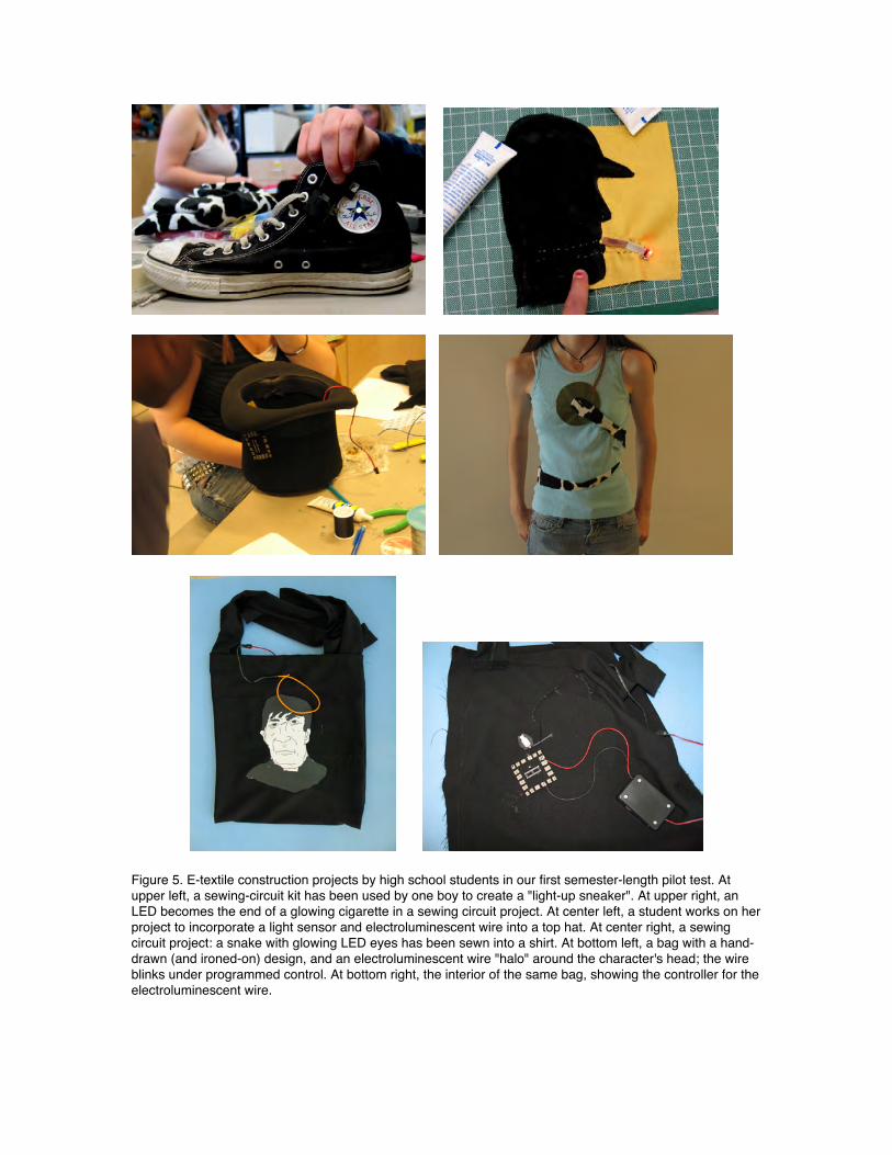
Figure 5. E-textile construction projects by high school students in our first semester-length pilot test. Atupper left, a sewing-circuit kit has been used by one boy to create a "light-up sneaker". At upper right, anLED becomes the end of a glowing cigarette in a sewing circuit project. At center left, a student works on herproject to incorporate a light sensor and electroluminescent wire into a top hat. At center right, a sewingcircuit project: a snake with glowing LED eyes has been sewn into a shirt. At bottom left, a bag with a hand-drawn (and ironed-on) design, and an electroluminescent wire "halo" around the character's head; the wireblinks under programmed control. At bottom right, the interior of the same bag, showing the controller for theelectroluminescent wire.
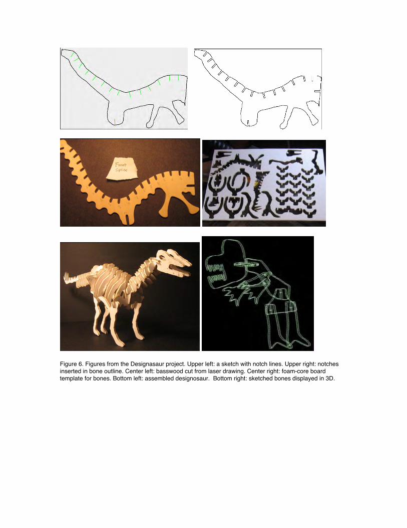
Figure 6. Figures from the Designasaur project. Upper left: a sketch with notch lines. Upper right: notchesinserted in bone outline. Center left: basswood cut from laser drawing. Center right: foam-core boardtemplate for bones. Bottom left: assembled designosaur. Bottom right: sketched bones displayed in 3D.
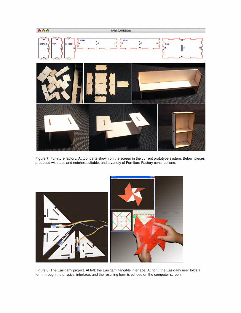
Figure 7. Furniture factory. At top: parts shown on the screen in the current prototype system. Below: piecesproduced with tabs and notches suitable, and a variety of Furniture Factory constructions.
Figure 8. The Easigami project. At left: the Easigami tangible interface. At right: the Easigami user folds aform through the physical interface, and the resulting form is echoed on the computer screen.
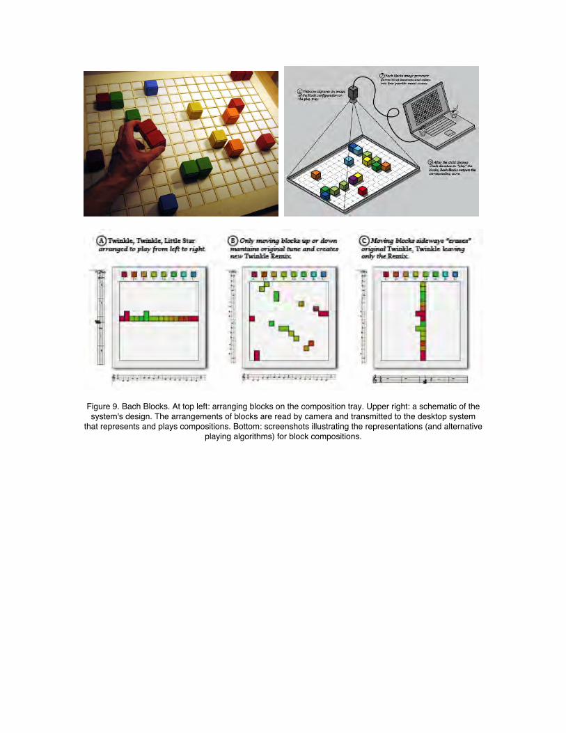
Figure 9. Bach Blocks. At top left: arranging blocks on the composition tray. Upper right: a schematic of thesystem's design. The arrangements of blocks are read by camera and transmitted to the desktop system
that represents and plays compositions. Bottom: screenshots illustrating the representations (and alternativeplaying algorithms) for block compositions.
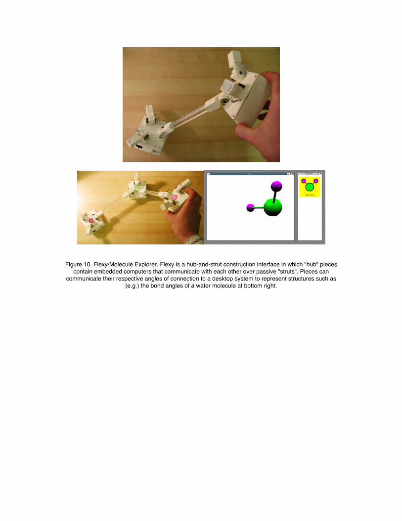
Figure 10. Flexy/Molecule Explorer. Flexy is a hub-and-strut construction interface in which "hub" piecescontain embedded computers that communicate with each other over passive "struts". Pieces can
communicate their respective angles of connection to a desktop system to represent structures such as(e.g.) the bond angles of a water molecule at bottom right.
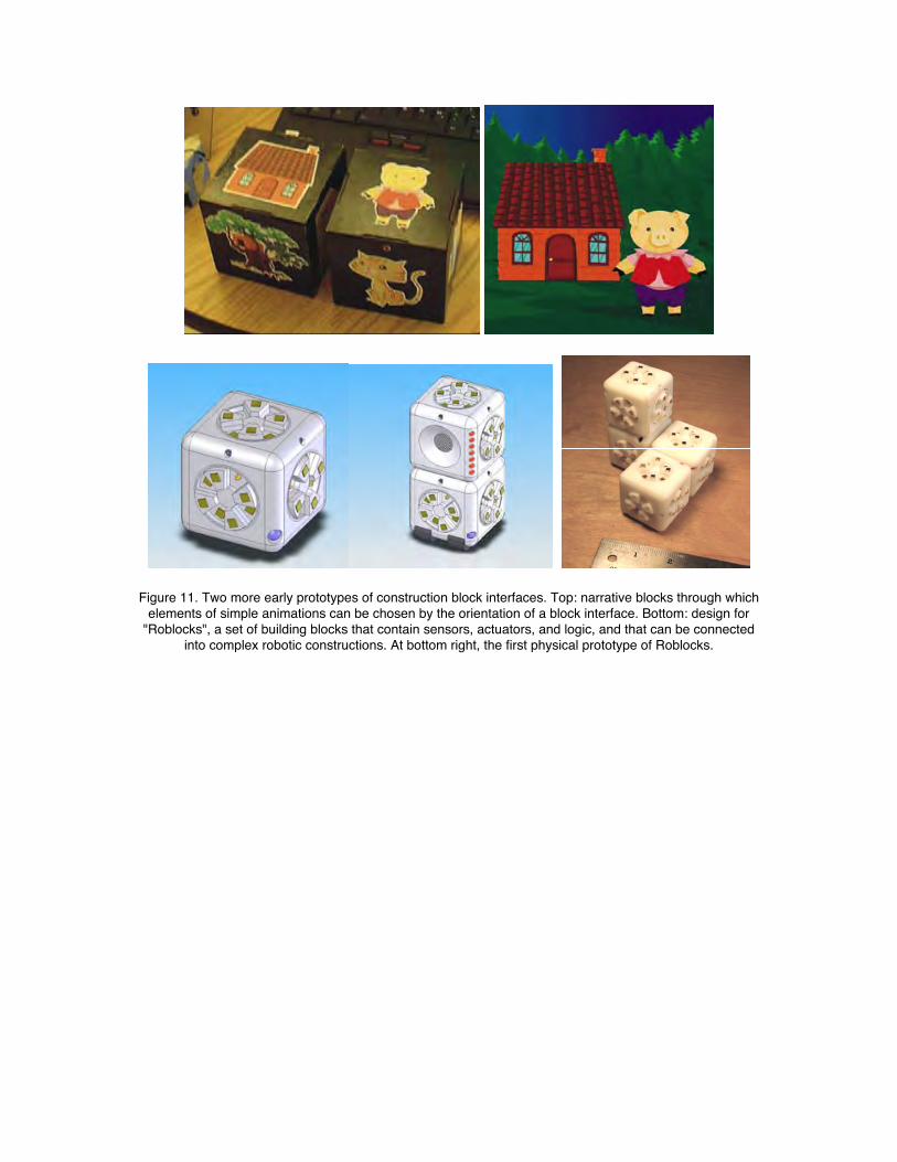
Figure 11. Two more early prototypes of construction block interfaces. Top: narrative blocks through whichelements of simple animations can be chosen by the orientation of a block interface. Bottom: design for
"Roblocks", a set of building blocks that contain sensors, actuators, and logic, and that can be connectedinto complex robotic constructions. At bottom right, the first physical prototype of Roblocks.
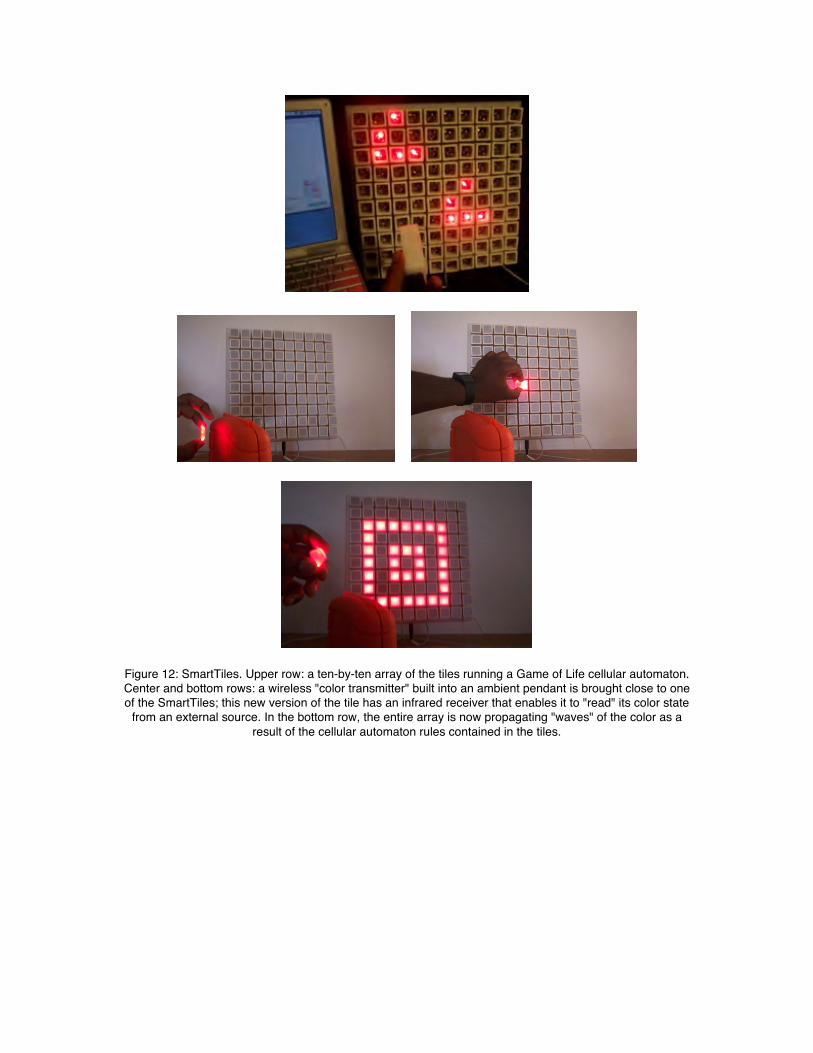
Figure 12: SmartTiles. Upper row: a ten-by-ten array of the tiles running a Game of Life cellular automaton.Center and bottom rows: a wireless "color transmitter" built into an ambient pendant is brought close to oneof the SmartTiles; this new version of the tile has an infrared receiver that enables it to "read" its color state
from an external source. In the bottom row, the entire array is now propagating "waves" of the color as aresult of the cellular automaton rules contained in the tiles.
Major presentations from Year 2 annual report (9/04-9/05):
• participation in a panel (Eisenberg), “Connecting with Kids: So what’s new?” at theACM SIGCHI conference (April 2-5, 2005) in Portland, OR.• paper presentation at ACM Creativity and Cognition conference Goldsmiths College.London 12-15 April 2005• paper presentation at IASTED conference on Education and Technology, Calgary, 4-6July 2005• paper presentation at IADIS International Conference Cognition and ExploratoryLearning in Digital Age (CELDA 2004) Lisbon, Portugal 15-17 December 2004
Prototypes Developed During Year 2 (9/04-9/05):
* Boda BlocksThe Boda Blocks kit consists of a set of glowing cubes that can be attached to oneanother with strut connector pieces. Users can interact with the kit by buildingconstructions, programming the blocks, setting the initial states of each block, andwatching constructions evolve. Each block contains a light emitting diode (LED) thatallows it to display state information and a switch that allows users to set its state. Blockscan also be plugged into a desktop machine and programmed. The type of programsblocks can receive depends on the domain the blocks have been assigned to model. Onceconstructions are built, they can be “executed”. In the executing phase, a constructionprogresses in discrete iterations; in each iteration every block updates its state based onthe states of its neighbor blocks.
* Telepresence TablesTwo wirelessly linked Telepresence Tables each contain an 8x8 grid of LEDs andphotosensors, allowing two-person play with grid based algorithms such as cellularautomata games. The grid of photosensors on each table capture patterns of shadow andlight made by hand gestures; red and yellow LEDs display patterns generatedalgorithmically as a function of the states of the two tables. A simple program, forexample, captures hand gestures on one table and displays them on the other table.
* Pop-Up and Fold-Out MakerPop-up and Fold-Out Maker is a sketch-based design environment for drawing pop-upand fold-out paper cards and producing them on a laser cutter. A user sketches shapes(such as a flower, a house, a tree); the program determines what lines should be erased toattach the shape to paper and where to place folding & cutting lines in order to create apop-up or fold-out, creates these lines, and generates cutting-folding HPGL code toproduce the card on a laser cutter.
* Energy CubeThe Energy Cube is a plastic block containing an orientation sensor and a tri-color (red,green, blue) light emitting diode (LED) on each face. It communicates orientationinformation by a wireless (RF) transceiver with a nearby personal computer, which inturn sets the block face colors. The test application of the Energy Cube was to provide anambient and dynamic display of energy consumption data gathered by a sensor networkand stored in a file on the PC. Each face represents a different room in the house, andglows a color between red and blue to indicate high or low energy use. Rotating the cubeposes a query to the PC that yields more details about the room whose face is up. Itshardware and software interface is general so cubes can be programmed to interact withinformation and applications from other domains.
* Espresso BlocksOur effort continued to develop a working version of the Espresso Block, a self-assembling modular robotic building block. A recent redesign of the block uses ABSplastic printed from a Dimension fused deposition modeler, aimed at producinginexpensive cast copies in polyurethane. In addition to developing the physical blocks,and a scheme that will allow a user to control their behavior by writing local rules, wehave been developing a graphical simulator that will enable the exploration of how theblocks can be controlled using local rules and constraints; the simulator can also be usedto understand the dynamic behavior of the Boda Blocks.
* ScrunchiesAs an example of hands-on craft that employs a combination of traditional and high techmaterials and manufacturing methods, undergraduate student Cami Dodson is developinga family of “Scrunchies”. A tube-like object that contracts and expands in a linearfashion, the first Scrunchy was designed using the Rhino 3d modeling program andprinted on a 3d rapid prototyping machine. A motor, controlled by a cricket from thePicoBlocks construction kit, turns the screw, extending the Scrunchy. Once fullyextended the motor reverses and screws the end piece back in. A solid fabric covers theScrunchy tube body and fur fabric on the ends accentuates movement. End users candecorate individual Scrunchies (e.g., googly-eyes added to the body). At the InteractionDesign for Children conference (June 2005) an informal display of the two Scrunchies satnext to each other. They moved up and down with slightly different timing; clothescrinkling and straightening, head turning slightly as, google-eyes wiggling. TheScrunchies appeared to be alive and they generated interest and amusement fromparticipants. To extend the project, several Scrunchies will attach to a multi-directionhub and users will control motion for each Scrunchy from simple to complex by addingpieces together, requiring the user to solve problems, explore and create.