computer graphics labs: blender (3/3): luxrender ... · pdf filecomputer graphics labs:...
TRANSCRIPT
Computer graphics Labs: Blender (3/3): LuxRender : rendering an outdoor
scene
Service de conception géométrique
Université de Liège –Department of Aerospace and Mechanical engineering
Designed with Blender 2.76b
2
Activating the LuxBlend Add-on As done in the second lab, we will use the LuxRender render engine. For this, activate the LuxBlend Add-on located in the window “Blender User Preferences” reachable via the menu File → User Preferences… Then change the current render engine ‘Blender render’ by ‘LuxRender’.
Creating the scene The aim of this practical course is to model an outdoor scene (showed on the last page). Throughout this tutorial we will get into generating the topology of the ground, linking textures for transparency effects (glazing) or geometric deformations (roofing), and using HDRI environment maps for embedding the scene into a realistic outdoor environment (sky with a full moon).
Firstly, the default cube will be used for constructing a building. We will then generate the ground.
Modelling the building In order to not change the scale factors associated to the cube faces, we will perform transformations directly on the mesh.
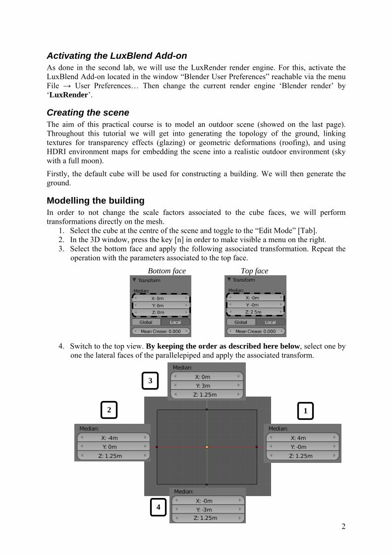
1. Select the cube at the centre of the scene and toggle to the “Edit Mode” [Tab]. 2. In the 3D window, press the key [n] in order to make visible a menu on the right. 3. Select the bottom face and apply the following associated transformation. Repeat the
operation with the parameters associated to the top face.
Bottom face Top face
4. Switch to the top view. By keeping the order as described here below, select one by
one the lateral faces of the parallelepiped and apply the associated transform.
12
3
4
3
5. Extrude de top face of the building by using the key [e] and setting the value 1.5 on the keypad. Confirm the extrusion with the key [Enter].
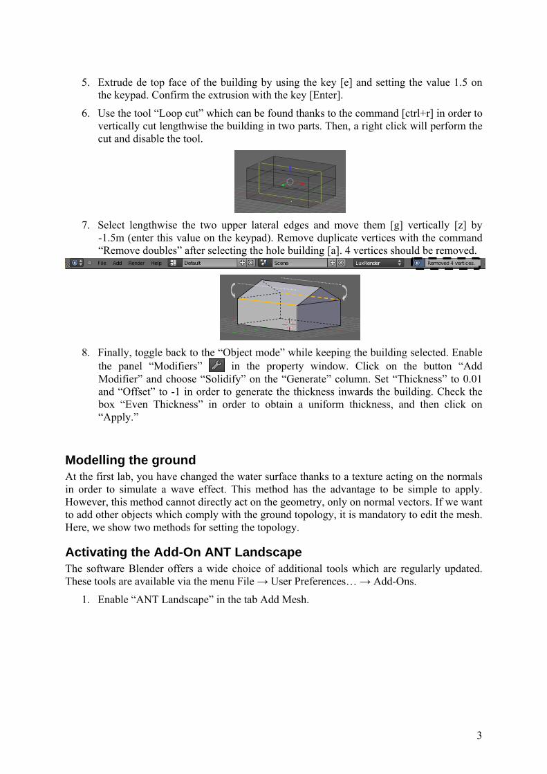
6. Use the tool “Loop cut” which can be found thanks to the command [ctrl+r] in order to vertically cut lengthwise the building in two parts. Then, a right click will perform the cut and disable the tool.
7. Select lengthwise the two upper lateral edges and move them [g] vertically [z] by
-1.5m (enter this value on the keypad). Remove duplicate vertices with the command “Remove doubles” after selecting the hole building [a]. 4 vertices should be removed.
8. Finally, toggle back to the “Object mode” while keeping the building selected. Enable
the panel “Modifiers” in the property window. Click on the button “Add Modifier” and choose “Solidify” on the “Generate” column. Set “Thickness” to 0.01 and “Offset” to -1 in order to generate the thickness inwards the building. Check the box “Even Thickness” in order to obtain a uniform thickness, and then click on “Apply.”
Modelling the ground At the first lab, you have changed the water surface thanks to a texture acting on the normals in order to simulate a wave effect. This method has the advantage to be simple to apply. However, this method cannot directly act on the geometry, only on normal vectors. If we want to add other objects which comply with the ground topology, it is mandatory to edit the mesh. Here, we show two methods for setting the topology.
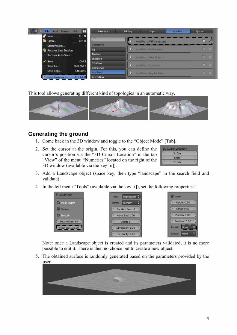
Activating the Add-On ANT Landscape The software Blender offers a wide choice of additional tools which are regularly updated. These tools are available via the menu File → User Preferences… → Add-Ons.
1. Enable “ANT Landscape” in the tab Add Mesh.
4
This tool allows generating different kind of topologies in an automatic way.
Generating the ground 1. Come back in the 3D window and toggle to the “Object Mode” [Tab].
2. Set the cursor at the origin. For this, you can define the cursor’s position via the “3D Cursor Location” in the tab “View” of the menu “Numerics” located on the right of the 3D window (available via the key [n]).
3. Add a Landscape object (space key, then type “landscape” in the search field and validate).
4. In the left menu “Tools” (available via the key [t]), set the following properties:
Note: once a Landscape object is created and its parameters validated, it is no more possible to edit it. There is then no choice but to create a new object.
5. The obtained surface is randomly generated based on the parameters provided by the user.
5
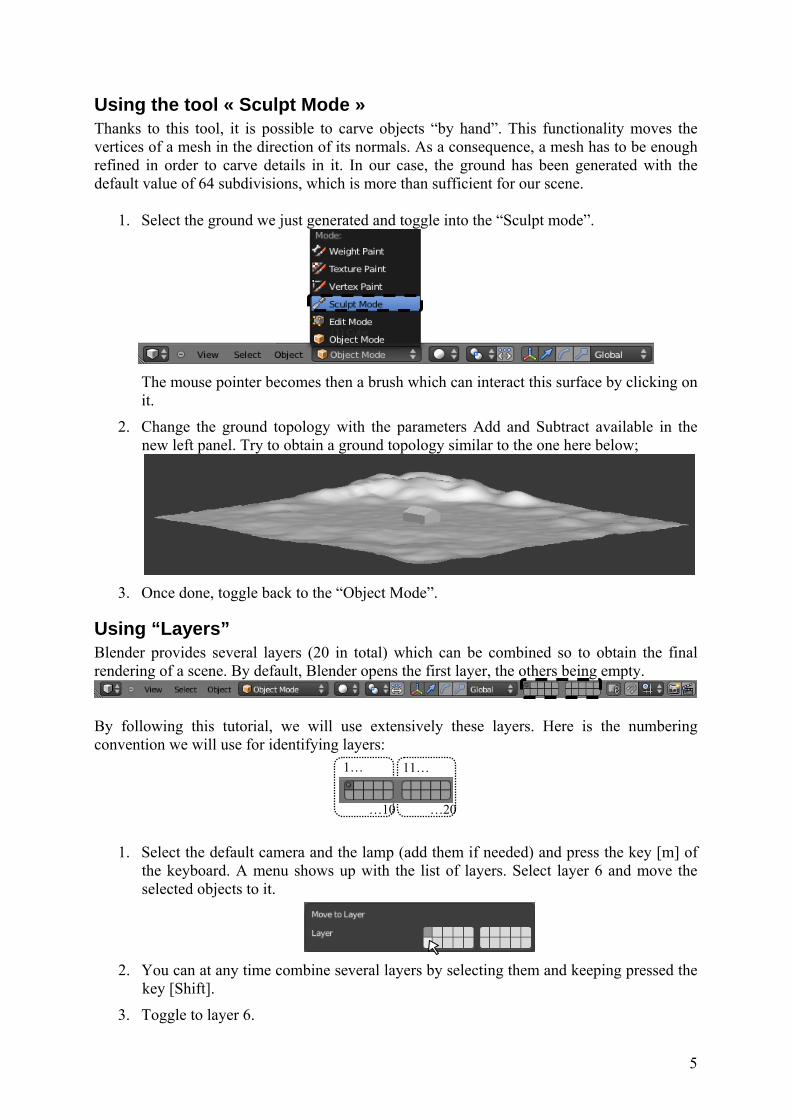
Using the tool « Sculpt Mode » Thanks to this tool, it is possible to carve objects “by hand”. This functionality moves the vertices of a mesh in the direction of its normals. As a consequence, a mesh has to be enough refined in order to carve details in it. In our case, the ground has been generated with the default value of 64 subdivisions, which is more than sufficient for our scene.
1. Select the ground we just generated and toggle into the “Sculpt mode”.
The mouse pointer becomes then a brush which can interact this surface by clicking on it.
2. Change the ground topology with the parameters Add and Subtract available in the new left panel. Try to obtain a ground topology similar to the one here below;
3. Once done, toggle back to the “Object Mode”.
Using “Layers” Blender provides several layers (20 in total) which can be combined so to obtain the final rendering of a scene. By default, Blender opens the first layer, the others being empty.
By following this tutorial, we will use extensively these layers. Here is the numbering convention we will use for identifying layers:
1. Select the default camera and the lamp (add them if needed) and press the key [m] of the keyboard. A menu shows up with the list of layers. Select layer 6 and move the selected objects to it.
2. You can at any time combine several layers by selecting them and keeping pressed the
key [Shift].
3. Toggle to layer 6.
1…
…10 …20
11…
6
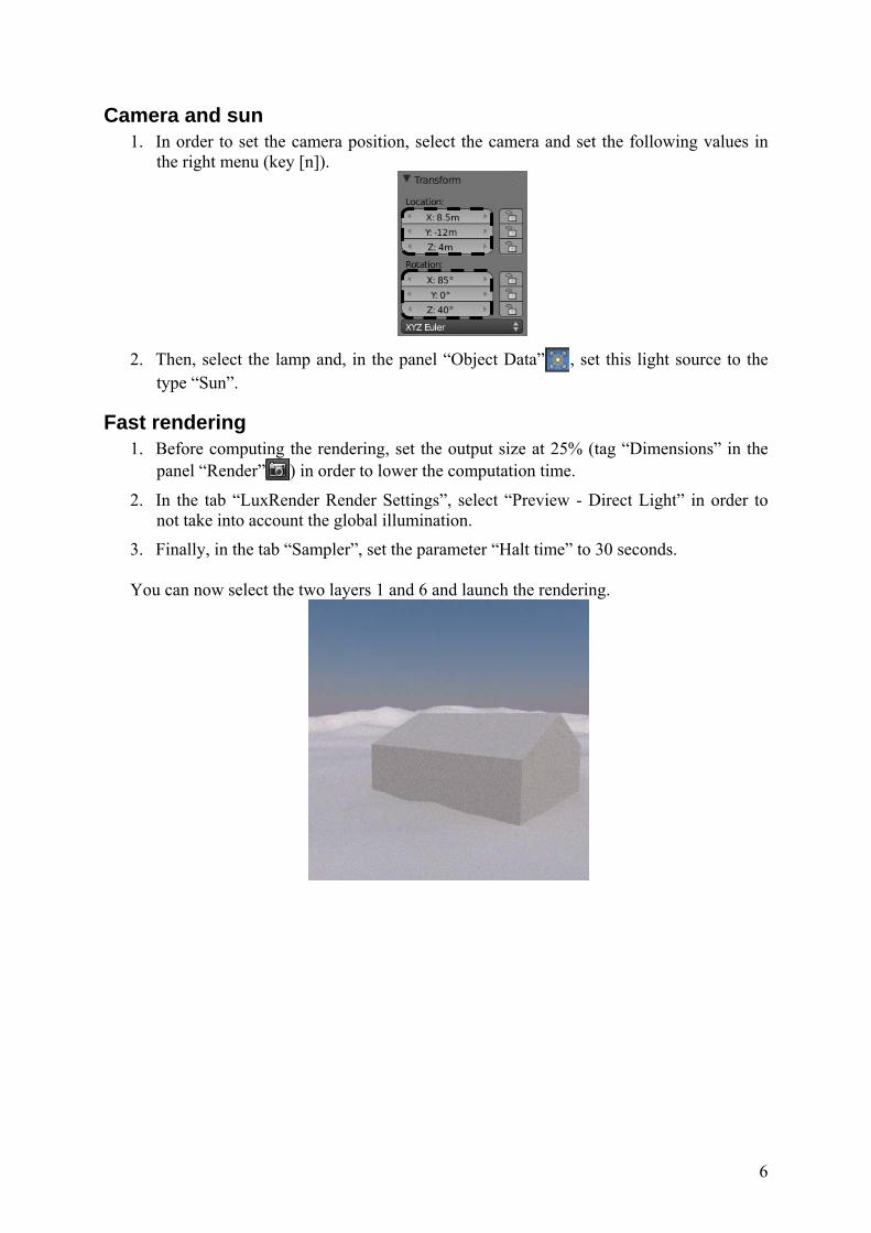
Camera and sun 1. In order to set the camera position, select the camera and set the following values in
the right menu (key [n]).
2. Then, select the lamp and, in the panel “Object Data” , set this light source to the
type “Sun”.
Fast rendering 1. Before computing the rendering, set the output size at 25% (tag “Dimensions” in the
panel “Render” ) in order to lower the computation time.
2. In the tab “LuxRender Render Settings”, select “Preview - Direct Light” in order to not take into account the global illumination.
3. Finally, in the tab “Sampler”, set the parameter “Halt time” to 30 seconds. You can now select the two layers 1 and 6 and launch the rendering.
7
“Texture”, “displacement” and “environment mapping” At the current state, the scene is quite bland because of the white mat material defined by default for different objects. We will now apply textures to the building and define a background landscape;
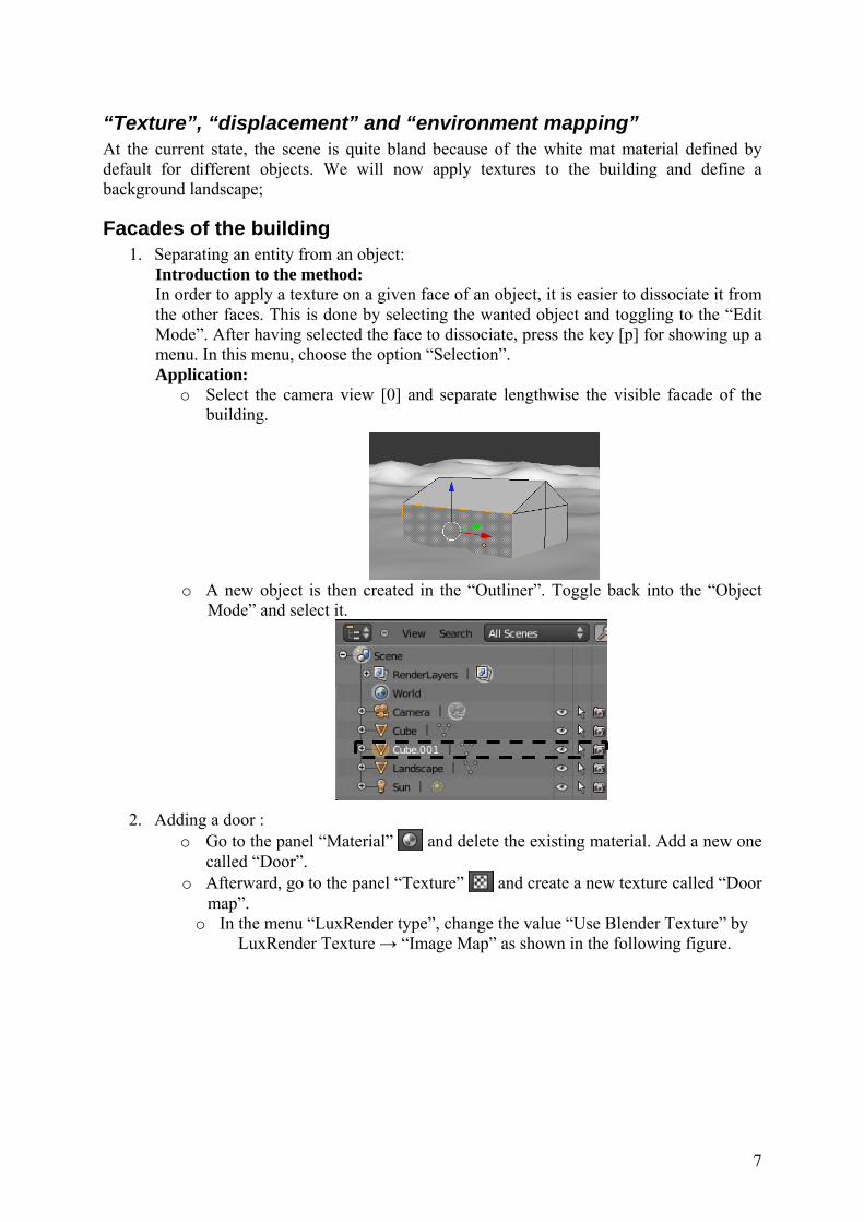
Facades of the building 1. Separating an entity from an object:
Introduction to the method: In order to apply a texture on a given face of an object, it is easier to dissociate it from the other faces. This is done by selecting the wanted object and toggling to the “Edit Mode”. After having selected the face to dissociate, press the key [p] for showing up a menu. In this menu, choose the option “Selection”. Application:
o Select the camera view [0] and separate lengthwise the visible facade of the building.
o A new object is then created in the “Outliner”. Toggle back into the “Object
Mode” and select it.
2. Adding a door :
o Go to the panel “Material” and delete the existing material. Add a new one called “Door”.
o Afterward, go to the panel “Texture” and create a new texture called “Door map”.
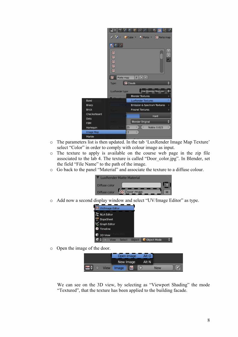
o In the menu “LuxRender type”, change the value “Use Blender Texture” by LuxRender Texture → “Image Map” as shown in the following figure.
8
o The parameters list is then updated. In the tab ‘LuxRender Image Map Texture’
select “Color” in order to comply with colour image as input. o The texture to apply is available on the course web page in the zip file
associated to the lab 4. The texture is called “Door_color.jpg”. In Blender, set the field “File Name” to the path of the image.
o Go back to the panel “Material” and associate the texture to a diffuse colour.
o Add now a second display window and select “UV/Image Editor” as type.
o Open the image of the door.
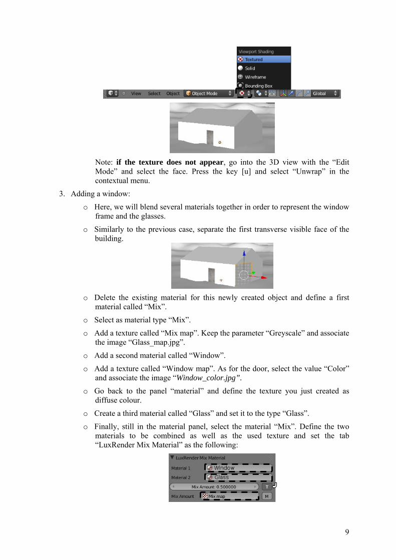
We can see on the 3D view, by selecting as “Viewport Shading” the mode “Textured”, that the texture has been applied to the building facade.
9
Note: if the texture does not appear, go into the 3D view with the “Edit Mode” and select the face. Press the key [u] and select “Unwrap” in the contextual menu.
3. Adding a window:
o Here, we will blend several materials together in order to represent the window frame and the glasses.
o Similarly to the previous case, separate the first transverse visible face of the building.
o Delete the existing material for this newly created object and define a first
material called “Mix”.
o Select as material type “Mix”.
o Add a texture called “Mix map”. Keep the parameter “Greyscale” and associate the image “Glass_map.jpg”.
o Add a second material called “Window”.
o Add a texture called “Window map”. As for the door, select the value “Color” and associate the image “Window_color.jpg”.
o Go back to the panel “material” and define the texture you just created as diffuse colour.
o Create a third material called “Glass” and set it to the type “Glass”.
o Finally, still in the material panel, select the material “Mix”. Define the two materials to be combined as well as the used texture and set the tab “LuxRender Mix Material” as the following:
10
Warning: - The ordering of the three materials is important,
- In order to check the application of each texture, you can refer to the note at the end of the previous stage number 2.
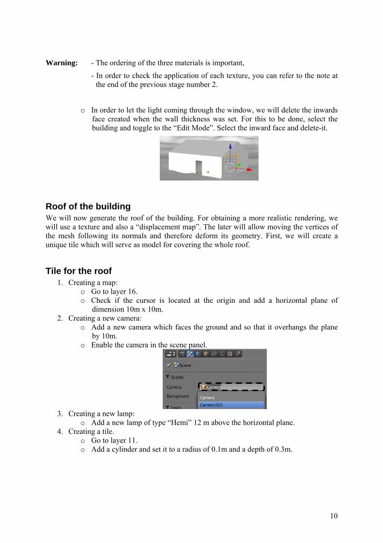
o In order to let the light coming through the window, we will delete the inwards face created when the wall thickness was set. For this to be done, select the building and toggle to the “Edit Mode”. Select the inward face and delete-it.
Roof of the building We will now generate the roof of the building. For obtaining a more realistic rendering, we will use a texture and also a “displacement map”. The later will allow moving the vertices of the mesh following its normals and therefore deform its geometry. First, we will create a unique tile which will serve as model for covering the whole roof.
Tile for the roof 1. Creating a map:
o Go to layer 16. o Check if the cursor is located at the origin and add a horizontal plane of
dimension 10m x 10m. 2. Creating a new camera:
o Add a new camera which faces the ground and so that it overhangs the plane by 10m.
o Enable the camera in the scene panel.
3. Creating a new lamp:
o Add a new lamp of type “Hemi” 12 m above the horizontal plane. 4. Creating a tile.
o Go to layer 11. o Add a cylinder and set it to a radius of 0.1m and a depth of 0.3m.

11
o After toggling to the “Edit Mode”, disable the button if needed. This allows the selection of hidden elements. Go to the top view, select the vertices of a half of the cylinder and delete them.
o Move the obtained surface so it touches the plane y=0.
o Click left on the origin in order to relocate the cursor and select as pivot point
the 3D cursor.
o Apply to the object a scaling following the y axes thanks to the command [s]
followed by [y]. You will obtain a flatter tile. o In order to give some volume to the tile, apply the modifier “Solidify” to the
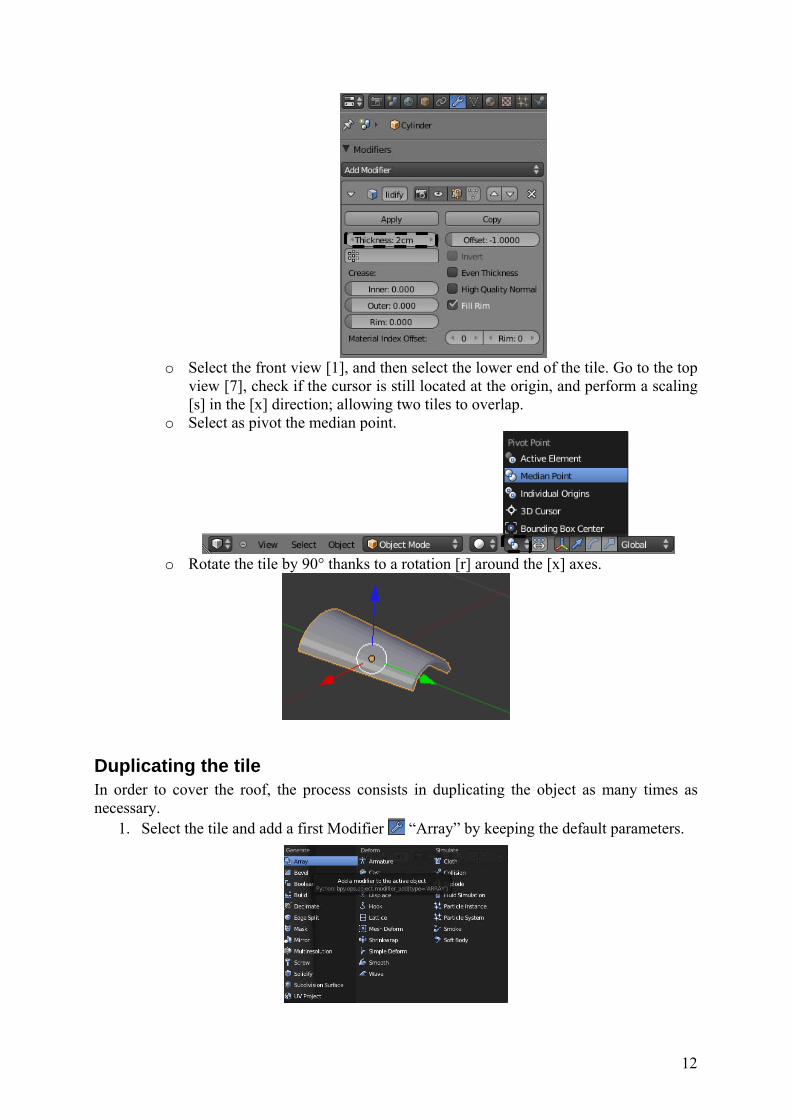
object. The chosen thickness is set to 0.02.
12
o Select the front view [1], and then select the lower end of the tile. Go to the top
view [7], check if the cursor is still located at the origin, and perform a scaling [s] in the [x] direction; allowing two tiles to overlap.
o Select as pivot the median point.
o Rotate the tile by 90° thanks to a rotation [r] around the [x] axes.
Duplicating the tile In order to cover the roof, the process consists in duplicating the object as many times as necessary.
1. Select the tile and add a first Modifier “Array” by keeping the default parameters.
13
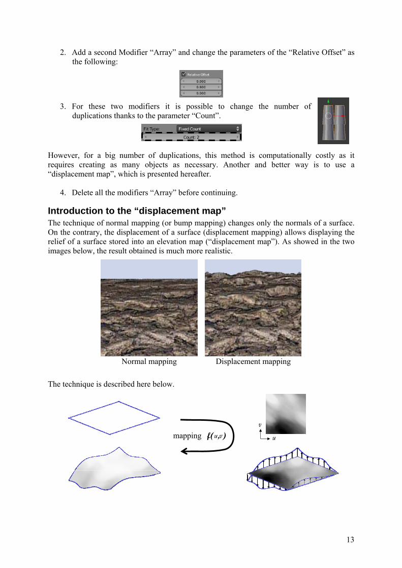
2. Add a second Modifier “Array” and change the parameters of the “Relative Offset” as the following:
3. For these two modifiers it is possible to change the number of
duplications thanks to the parameter “Count”.
However, for a big number of duplications, this method is computationally costly as it requires creating as many objects as necessary. Another and better way is to use a “displacement map”, which is presented hereafter.
4. Delete all the modifiers “Array” before continuing.
Introduction to the “displacement map” The technique of normal mapping (or bump mapping) changes only the normals of a surface. On the contrary, the displacement of a surface (displacement mapping) allows displaying the relief of a surface stored into an elevation map (“displacement map”). As showed in the two images below, the result obtained is much more realistic.
Normal mapping Displacement mapping
The technique is described here below.
f(u,v) u
v mapping
14
From a mesh and an elevation map, a “mapping” function is used in order to associate an elevation value to each point of the mesh. The mesh is then deformed according to this values and the direction of the normal to the surface.
The next step introduces a tool which will generate an elevation map associated to the tile.
Introduction to the “Node Editor” The nodes system of Blender allows the design of new materials (“Material Nodes”), textures (“Texture Nodes”) and the post-processing (“Compositing Nodes”) of an image or film obtained thanks to the render engine. The buttons, field values and drop down menus of Blender allows the user to enter data which will affect the final rendering. The “Node Editor” offers a graphical display of the processing and flux of these data.
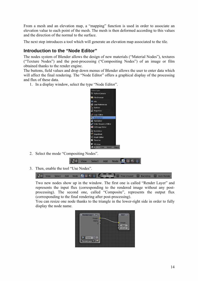
1. In a display window, select the type “Node Editor”.
2. Select the mode “Compositing Nodes”.
3. Then, enable the tool “Use Nodes”.
Two new nodes show up in the window. The first one is called “Render Layer” and represents the input flux (corresponding to the rendered image without any post-processing). The second one, called “Composite”, represents the output flux (corresponding to the final rendering after post-processing). You can resize one node thanks to the triangle in the lower-right side in order to fully display the node name.
15
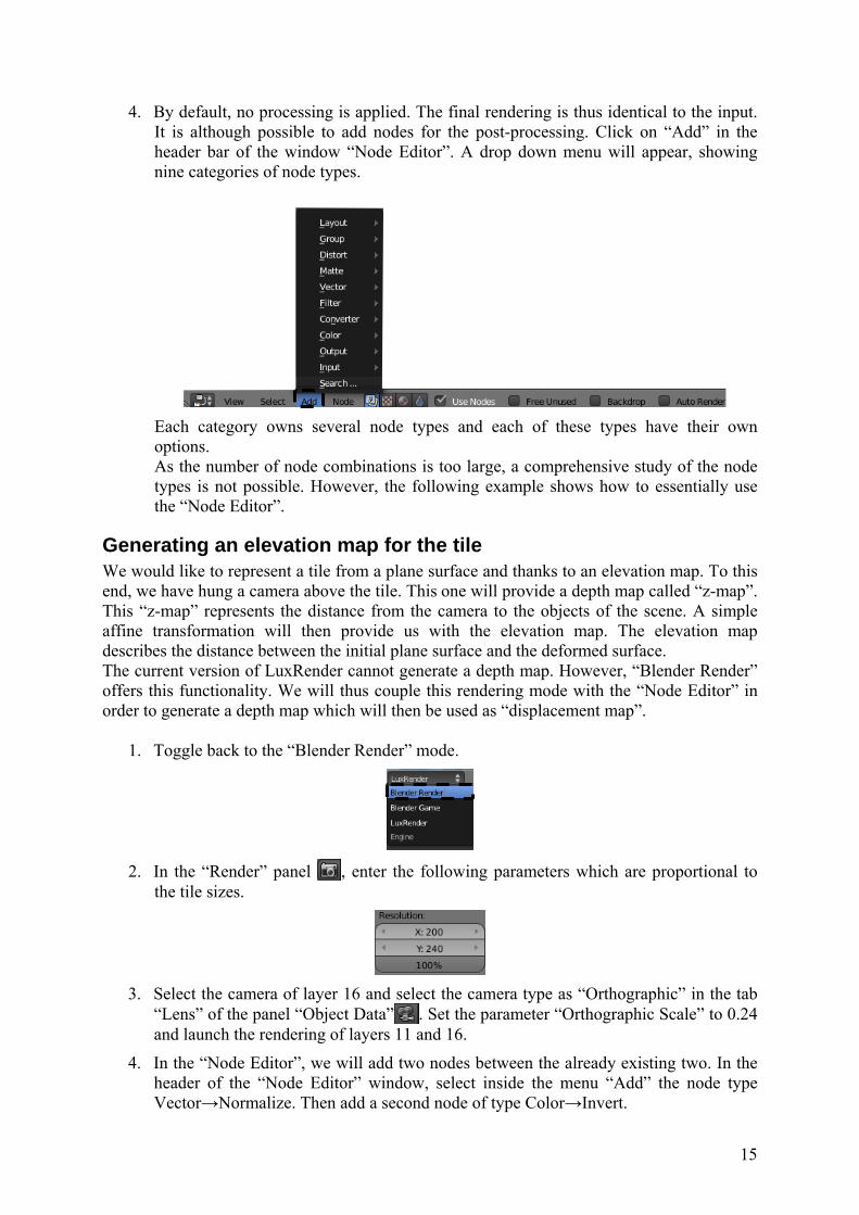
4. By default, no processing is applied. The final rendering is thus identical to the input. It is although possible to add nodes for the post-processing. Click on “Add” in the header bar of the window “Node Editor”. A drop down menu will appear, showing nine categories of node types.
Each category owns several node types and each of these types have their own options. As the number of node combinations is too large, a comprehensive study of the node types is not possible. However, the following example shows how to essentially use the “Node Editor”.
Generating an elevation map for the tile We would like to represent a tile from a plane surface and thanks to an elevation map. To this end, we have hung a camera above the tile. This one will provide a depth map called “z-map”. This “z-map” represents the distance from the camera to the objects of the scene. A simple affine transformation will then provide us with the elevation map. The elevation map describes the distance between the initial plane surface and the deformed surface. The current version of LuxRender cannot generate a depth map. However, “Blender Render” offers this functionality. We will thus couple this rendering mode with the “Node Editor” in order to generate a depth map which will then be used as “displacement map”.
1. Toggle back to the “Blender Render” mode.
2. In the “Render” panel , enter the following parameters which are proportional to
the tile sizes.
3. Select the camera of layer 16 and select the camera type as “Orthographic” in the tab
“Lens” of the panel “Object Data” . Set the parameter “Orthographic Scale” to 0.24 and launch the rendering of layers 11 and 16.
4. In the “Node Editor”, we will add two nodes between the already existing two. In the header of the “Node Editor” window, select inside the menu “Add” the node type Vector→Normalize. Then add a second node of type Color→Invert.
16
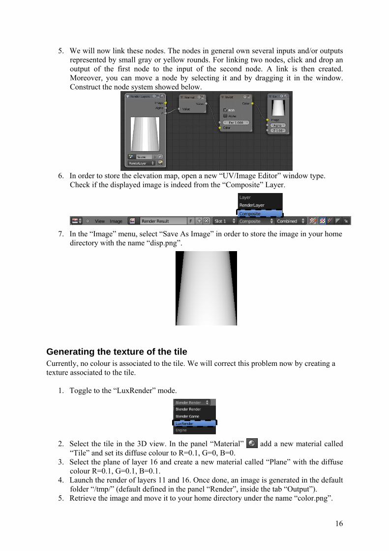
5. We will now link these nodes. The nodes in general own several inputs and/or outputs represented by small gray or yellow rounds. For linking two nodes, click and drop an output of the first node to the input of the second node. A link is then created. Moreover, you can move a node by selecting it and by dragging it in the window. Construct the node system showed below.
6. In order to store the elevation map, open a new “UV/Image Editor” window type.
Check if the displayed image is indeed from the “Composite” Layer.
7. In the “Image” menu, select “Save As Image” in order to store the image in your home
directory with the name “disp.png”.
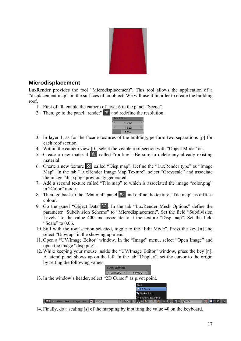
Generating the texture of the tile Currently, no colour is associated to the tile. We will correct this problem now by creating a texture associated to the tile.
1. Toggle to the “LuxRender” mode.
2. Select the tile in the 3D view. In the panel “Material” add a new material called
“Tile” and set its diffuse colour to R=0.1, G=0, B=0. 3. Select the plane of layer 16 and create a new material called “Plane” with the diffuse
colour R=0.1, G=0.1, B=0.1. 4. Launch the render of layers 11 and 16. Once done, an image is generated in the default
folder “/tmp/” (default defined in the panel “Render”, inside the tab “Output”). 5. Retrieve the image and move it to your home directory under the name “color.png”.
17
Microdisplacement LuxRender provides the tool “Microdisplacement”. This tool allows the application of a “displacement map” on the surfaces of an object. We will use it in order to create the building roof.
1. First of all, enable the camera of layer 6 in the panel “Scene”. 2. Then, go to the panel “render” and redefine the resolution.
3. In layer 1, as for the facade textures of the building, perform two separations [p] for
each roof section. 4. Within the camera view [0], select the visible roof section with “Object Mode” on. 5. Create a new material called “roofing”. Be sure to delete any already existing
material. 6. Create a new texture called “Disp map”. Define the “LuxRender type” as “Image
Map”. In the tab “LuxRender Image Map Texture”, select “Greyscale” and associate the image “disp.png” previously generated.
7. Add a second texture called “Tile map” to which is associated the image “color.png” in “Color” mode.
8. Then, go back to the “Material” panel and define the texture “Tile map” as diffuse colour.
9. Go the panel “Object Data” . In the tab “LuxRender Mesh Options” define the parameter “Subdivision Scheme” to “Microdisplacement”. Set the field “Subdivision Levels” to the value 400 and associate to it the texture “Disp map”. Set the field “Scale” to 0.06.
10. Still with the roof section selected, toggle to the “Edit Mode”. Press the key [u] and select “Unwrap” in the showing up menu.
11. Open a “UV/Image Editor” window. In the “Image” menu, select “Open Image” and open the image “disp.png”.
12. While keeping your mouse inside the “UV/Image Editor” window, press the key [n]. A lateral panel shows up on the left. In the tab “Display”, set the cursor to the origin by setting the following values.
13. In the window’s header, select “2D Cursor” as pivot point.
14. Finally, do a scaling [s] of the mapping by inputting the value 40 on the keyboard.
18
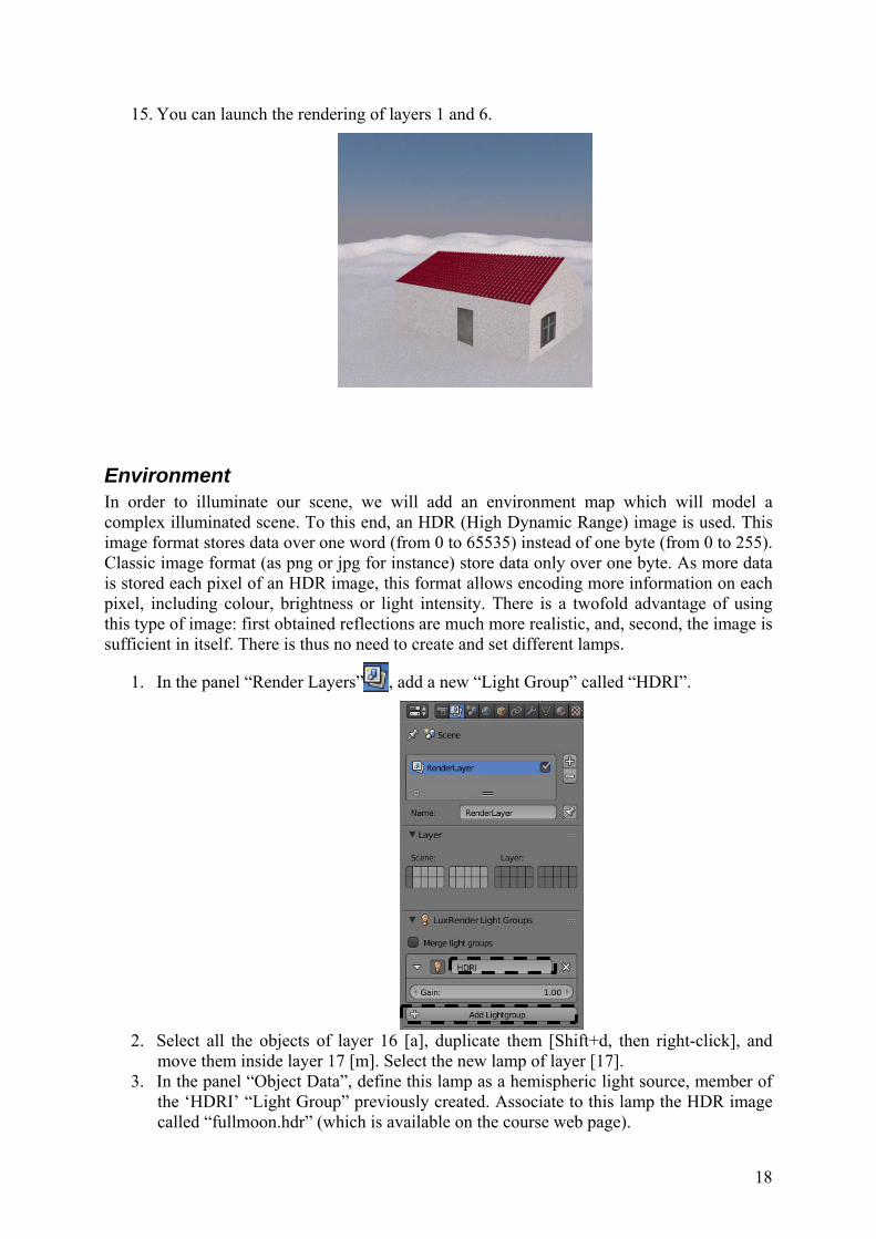
15. You can launch the rendering of layers 1 and 6.
Environment In order to illuminate our scene, we will add an environment map which will model a complex illuminated scene. To this end, an HDR (High Dynamic Range) image is used. This image format stores data over one word (from 0 to 65535) instead of one byte (from 0 to 255). Classic image format (as png or jpg for instance) store data only over one byte. As more data is stored each pixel of an HDR image, this format allows encoding more information on each pixel, including colour, brightness or light intensity. There is a twofold advantage of using this type of image: first obtained reflections are much more realistic, and, second, the image is sufficient in itself. There is thus no need to create and set different lamps.
1. In the panel “Render Layers” , add a new “Light Group” called “HDRI”.
2. Select all the objects of layer 16 [a], duplicate them [Shift+d, then right-click], and
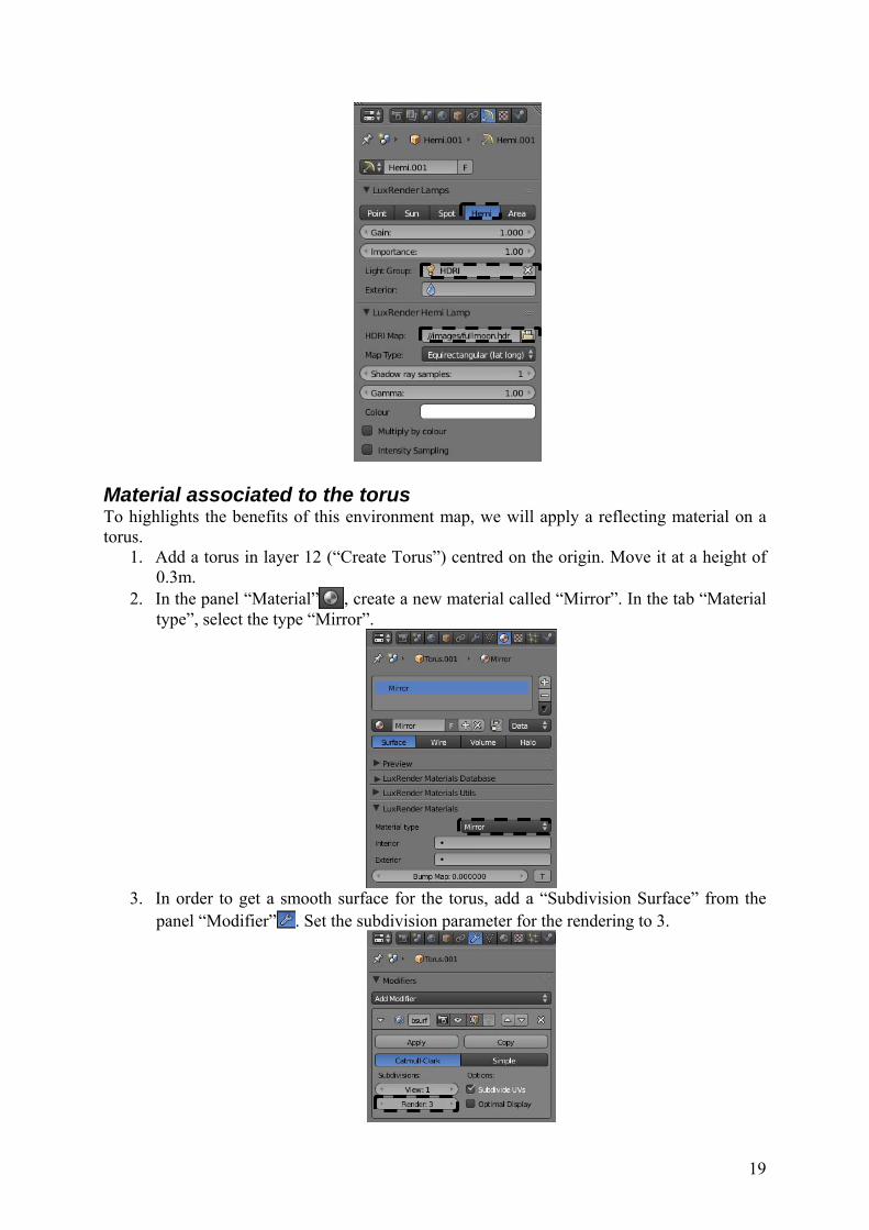
move them inside layer 17 [m]. Select the new lamp of layer [17]. 3. In the panel “Object Data”, define this lamp as a hemispheric light source, member of
the ‘HDRI’ “Light Group” previously created. Associate to this lamp the HDR image called “fullmoon.hdr” (which is available on the course web page).
19
Material associated to the torus To highlights the benefits of this environment map, we will apply a reflecting material on a torus.
1. Add a torus in layer 12 (“Create Torus”) centred on the origin. Move it at a height of 0.3m.
2. In the panel “Material” , create a new material called “Mirror”. In the tab “Material type”, select the type “Mirror”.
3. In order to get a smooth surface for the torus, add a “Subdivision Surface” from the
panel “Modifier” . Set the subdivision parameter for the rendering to 3.

20
4. Enable the camera of layer 17 and toggle back in “Perspective” mode for this camera. Delete the material associated to the plane of layer 17. Select the both layers 12 and 17 and render the scene.
21
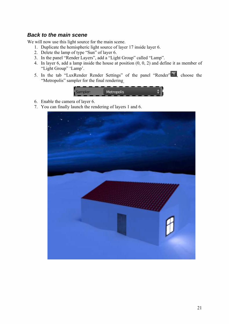
Back to the main scene We will now use this light source for the main scene.
1. Duplicate the hemispheric light source of layer 17 inside layer 6. 2. Delete the lamp of type “Sun” of layer 6. 3. In the panel “Render Layers”, add a “Light Group” called “Lamp”. 4. In layer 6, add a lamp inside the house at position (0, 0, 2) and define it as member of
“Light Group” ‘Lamp’. 5. In the tab “LuxRender Render Settings” of the panel “Render” , choose the
“Metropolis” sampler for the final rendering.
6. Enable the camera of layer 6. 7. You can finally launch the rendering of layers 1 and 6.