computer network multimedia guy leduc chapter 2 mpls...
TRANSCRIPT

1
© From Computer Networking, by Kurose&Ross MPLS 2-1
Computer Network Architectures and Multimedia
Guy Leduc
Chapter 2 MPLS networks
Chapter based on
Section 5.5 of Computer Networking: A Top Down Approach, 6th edition. Jim Kurose, Keith Ross Addison-Wesley, March 2012.
Section 1.1.3 and chapter 2 of MPLS - Technology and Applications. Bruce Davie, Yakov Rekhter. Morgan Kaufmann, 2000.
Chapter 6 of ACM SIGCOMM eBook on Recent Advances in Networking, 2013. http://www.sigcomm.org/content/ebook
© From Computer Networking, by Kurose&Ross MPLS 2-2
Chapter 2: MPLS
Overview ❒ Virtual Circuits (VC) - Reminder ❒ MPLS networks ❒ MPLS Virtual Private Networks (VPNs)

2
© From Computer Networking, by Kurose&Ross MPLS 2-3
VC forwarding table (1)
Incoming interface Incoming VC # Outgoing interface Outgoing VC #
1 12 3 22 3 22 1 12
… … … …
Forwarding table in northwest router:
Need incoming interface number in table!
12 22 32
1 2 3
VC number interface number
Model #1 : VC number is link local
© From Computer Networking, by Kurose&Ross MPLS 2-4
VC forwarding table (2)
Incoming VC # Outgoing interface Outgoing VC #
12 3 22 22 1 12
… … …
Forwarding table in northwest router:
VC number is unique in the node. Incoming VC number is enough to identify a VC
12 22 32
1 2 3
VC number interface number
Model #2 : VC number is node local

3
© From Computer Networking, by Kurose&Ross MPLS 2-5
Chapter 2: MPLS
Overview ❒ Virtual Circuits (VC) - Reminder ❒ MPLS networks ❒ MPLS Virtual Private Networks (VPNs)
© From Computer Networking, by Kurose&Ross MPLS 2-6
MultiProtocol Label Switching (MPLS) ❒ Initial goal: high-speed IP forwarding by using fixed
length label (instead of IP address) to do forwarding ❍ fast lookup using fixed length identifier (rather than
longest prefix matching) ❍ borrowing ideas from Virtual Circuit (VC) approach ❍ but IP datagram inside still keeps IP address!
Data link header
IP header remainder of link-layer frame MPLS header
label Exp S TTL
20 3 1 5
The label is the main field. Others will be explained later

4
© From Computer Networking, by Kurose&Ross MPLS 2-7
IP-Over-MPLS Classic IP only (e.g., over Ethernet) ❒ 3 “networks” (e.g., LANs) ❒ MAC (802.3) and IP addresses
IP over MPLS ❒ MPLS network seen as “layer 2”
network (like an Ethernet LAN) ❒ MPLS labels and IP addresses
MPLS network
Ethernet LANs
Ethernet LANs
= IP router with MPLS switching capabilities
= Ethernet switch
= IP router
© From Computer Networking, by Kurose&Ross MPLS 2-8
MPLS-capable (IP) routers ❒ a.k.a. Label-Switched Router (LSR) ❒ Forwards packets to outgoing interface based only on
label value (don’t inspect IP address) ❍ MPLS forwarding table distinct from IP forwarding table
❒ Flexibility: MPLS forwarding decisions can differ from those of IP ❍ Labels can be based on destination and source addresses and
TOS byte, so that flows can be routed to the same destination differently (traffic engineering)
❍ Possible to re-route flows quickly if link fails: pre-computed backup paths (useful for real-time flows such as VoIP)
❒ Signaling protocol is needed to set up forwarding state based on labels in nodes
❒ Must co-exist with IP-only routers

5
© From Computer Networking, by Kurose&Ross MPLS 2-9
MPLS versus IP paths (1)
R2
D R3
R5
A
R6
IP router
R4
❒ IP routing: path to destination determined by destination address alone
❒ All paths towards a given destination form a tree rooted at this destination
© From Computer Networking, by Kurose&Ross MPLS 2-10
MPLS versus IP paths (2)
R2
D R3 R4
R5
A
R6 IP-only router
MPLS and IP router
entry router (R4) can use different MPLS routes to A based, e.g., on source address
❒ IP routing: path to destination determined by destination address alone
❒ MPLS routing: path to destination can be based, e.g., on source and destination addresses, and/or TOS byte, and/or on available link resources, and/or on link performance metrics

6
© From Computer Networking, by Kurose&Ross MPLS 2-11
MPLS signaling for traffic engineering
❒ Extend the intra-domain routing protocol ❍ OSPF and IS-IS link state packets can carry additional link
information used by MPLS
D R4
R5
A
R6
❒ Establish MPLS paths (i.e., forwarding state based on labels) ❍ Done by ingress MPLS router, typically by RSVP-TE (see later)
modified link state flooding
RSVP-TE
© From Computer Networking, by Kurose&Ross MPLS 2-12
R1 R2
D R3 R4
R5 0
1 0 0
A
R6
in out out label label dest interface
6 - A 0
in out out label label dest interface
10 6 A 1 12 9 D 0
in out out label label dest interface
10 A 0 12 D 0
1
in out out label label dest interface
8 6 A 0
0
8 A 1
MPLS forwarding tables
IP-only router Ingress
LSR
Note the merging on label 6
Note the splitting in R4 to reach A

7
© From Computer Networking, by Kurose&Ross MPLS 2-13
Network Layer Routing Functional Components
❒ Routing and Forwarding ❒ Routing (control plane)
❍ Routing algorithm: build routing tables ❒ Forwarding (data plane)
❍ Forward packets according to forwarding tables derived from routing tables
❒ Unicast IP forwarding: ❍ Uses IP destination address prefix ❍ Longest prefix match
❒ Unicast IP forwarding with Types of Service ❍ Uses destination address prefix and TOS value ❍ Longest prefix match on address prefix and exact match on TOS
❒ Multicast forwarding ❍ Uses destination and source addresses and incoming interface ❍ Exact match
© From Computer Networking, by Kurose&Ross MPLS 2-14
Forwarding Equivalence Class (FEC) ❒ The set of all possible packets can be partitioned into disjoint
subsets according to the forwarding point of view ❍ A Forwarding Equivalence Class (FEC) is such a subset ❍ All packets in a FEC are forwarded in the same way
❒ Examples of FECs: ❍ A set of unicast packets whose destination address matches a
particular IP address prefix ❍ A set of unicast packets with the same TOS and whose destination
address matches a particular IP address prefix ❍ A set of unicast packets whose source and destination addresses
match particular IP address prefixes (load sharing) ❍ A set of multicast packets with the same source and destination
addresses ❒ All granularities are possible provided that they are based on the
IP header fields (+ possibly the port numbers and the incoming interface) ❍ Trade-off between granularity and scalability

8
© From Computer Networking, by Kurose&Ross MPLS 2-15
Label Switching: The Forwarding Component
❒ Every packet has a label ❍ A label is a short, fixed-length (20 bits) entity, with no internal structure ❍ It’s a Virtual Circuit Identifier (VCI)
❒ Forwarding will be based solely on labels (+ possibly on the incoming interface if label is link local)
❒ Forwarding entry: Incoming label → {components} ❍ component = (outgoing label, outgoing interface, next-hop, other fields)
• Next hop = the IP address of end of MPLS tunnel • Examples of other fields: an outgoing queue (for QoS) • Labels are thus swapped by nodes
❒ Single forwarding algorithm! ❍ Not one for unicast, one for multicast, one for unicast + TOS, …
❒ No constraint on the forwarding granularity ❍ A label can be associated with any chosen FEC
❒ Paths followed by labeled IP packets are called LSPs ❍ Label-Switched Paths
© From Computer Networking, by Kurose&Ross MPLS 2-16
Multiprotocol: Above and Below
❒ Label switching is not specific to any particular network layer
❒ Label switching can operate over any link layer protocol ❒ MPLS = Multiprotocol Label Switching
Label Switching
IPv4 IPv6 IPX …
Ethe
rnet
ATM
FDD
I
Fram
e Re
lay
PPP
Network layer protocols
Data link layer protocols
Sort of layer 2.5

9
© From Computer Networking, by Kurose&Ross MPLS 2-17
Label Switching: The Control Component
❒ The control component is responsible for ❍ Distributing routing information among LSRs ❍ The procedures for converting this information into a forwarding table
• Create bindings between labels and FECs • Distribute bindings among LSRs
Network layerrouting protocols
(e.g. OSPF, BGP, PIM)
Procedures forcreating bindings
between FECs and labels
Procedures fordistributing label
binding information
Label switching forwarding table(label-to-next-hop mapping)
FEC-to-label mappingFEC-to-next-hop mapping
© From Computer Networking, by Kurose&Ross MPLS 2-18
Local versus Remote Binding ❒ Local binding
❍ An LSR creates the binding with a label that is chosen and assigned locally
• Example: LSR A locally assigns label 100 to FEC 139.165.11.* ❒ Remote binding
❍ An LSR receives a label binding from another LSR • A’s neighbor LSR B informs A that it has assigned label 105
to FEC 139.165.11.* – Interesting for A if A is using B as next hop for this FEC, because
A can start sending packets with label 105 to B for this FEC – If so, A stores this mapping in its forwarding table:
100 → (105, outgoing_interface_to_B) – Otherwise, A discards it (or stores it as a backup entry)
• Similarly, A will inform its neighbors about its local mapping 100 for FEC 139.165.11.*, so that they can send A packets labeled by 100

10
© From Computer Networking, by Kurose&Ross MPLS 2-19
Forwarding tables in LSRs
Routing: 139.165.11.* → CLocal binding: 139.165.11.* → 105MPLS forwarding: 105 → (?, C)
Routing: 139.165.11.* → BLocal binding: 139.165.11.* → 100MPLS forwarding: 100 → (105, B)
AB
Routing: 139.165.11.* → ALocal binding: 139.165.11.* → 103MPLS forwarding: 103 → (100, A)
Routing: 139.165.11.* → ALocal binding: 139.165.11.* → 107MPLS forwarding: 107 → (100, A)
C
Consider forwarding entries for FEC = 139.165.11.*
© From Computer Networking, by Kurose&Ross MPLS 2-20
This is called Downstream Binding
Packets withlabel X
BindingInformationfor label X
Packets withlabel X
BindingInformationfor label X
Downstream binding Upstream binding
Upstream = “on the source side”Downstream = “on the sink side”

11
© From Computer Networking, by Kurose&Ross MPLS 2-21
LDP: Label Distribution Protocol
❒ LDP is a signaling protocol to distribute FEC-to-label bindings among LSRs
❒ The routing protocol (e.g. OSPF) is still useful to distribute FEC-to-NextHop bindings ❍ That is the network topology information ❍ Possibly extended with QoS-related link metrics (link delay,
link capacity, etc.) ❒ Note: if FECs are just the traditional destination IP
prefixes, the MPLS LSPs will simply follow the IP shortest paths ❍ Label switching ❍ But no clever routing, no traffic engineering!
© From Computer Networking, by Kurose&Ross MPLS 2-22
Establishing LSPs using RSVP ❒ RSVP = Resource ReserVation Protocol
❍ RSVP covered in more details in chap. 5 ❍ Source sends PATH message to destination
• Route taken by PATH is dictated by IP routing! ❍ Destination replies using RESV message
• Following the same route (backward) as the PATH message • Here RESV also used to piggyback MPLS labels!
Path
ResvLabel = 9
Path
ResvLabel = 5
IngressLSR
EgressLSR

12
© From Computer Networking, by Kurose&Ross MPLS 2-23
But: IP routing is not always a panacea
❒ Fish problem: ❍ If the shortest path from C to G is CDG, then all flows from A to G and B to G
use the CDG path, which is congested, while CEFG remains unused ❍ If traffic load is taken into account, this simply leads to oscillations
❒ One needs some load balancing ❍ OSPF can keep several routes for a destination when they are equal
• ECMP: Equal Cost MultiPath • This is not enough in the example above
A
B E
C G
D
F
© From Computer Networking, by Kurose&Ross MPLS 2-24
Other routing requirements ❒ Efficient explicit (aka source) routing
❍ Explicit routing is possible in IP • Add a route in the optional part of the IP header • But big overhead! • And most often not taken into account by ISPs
❒ Constraint-based routing ❍ Find a route with a given minimal bandwidth ❍ Find a route with a given maximal delay ❍ OSPF can find shortest paths according to several metrics
• But this is not equivalent ❒ All these requirements are traffic engineering
requirements ❍ And IP offers little support to traffic engineering
13
© From Computer Networking, by Kurose&Ross MPLS 2-25
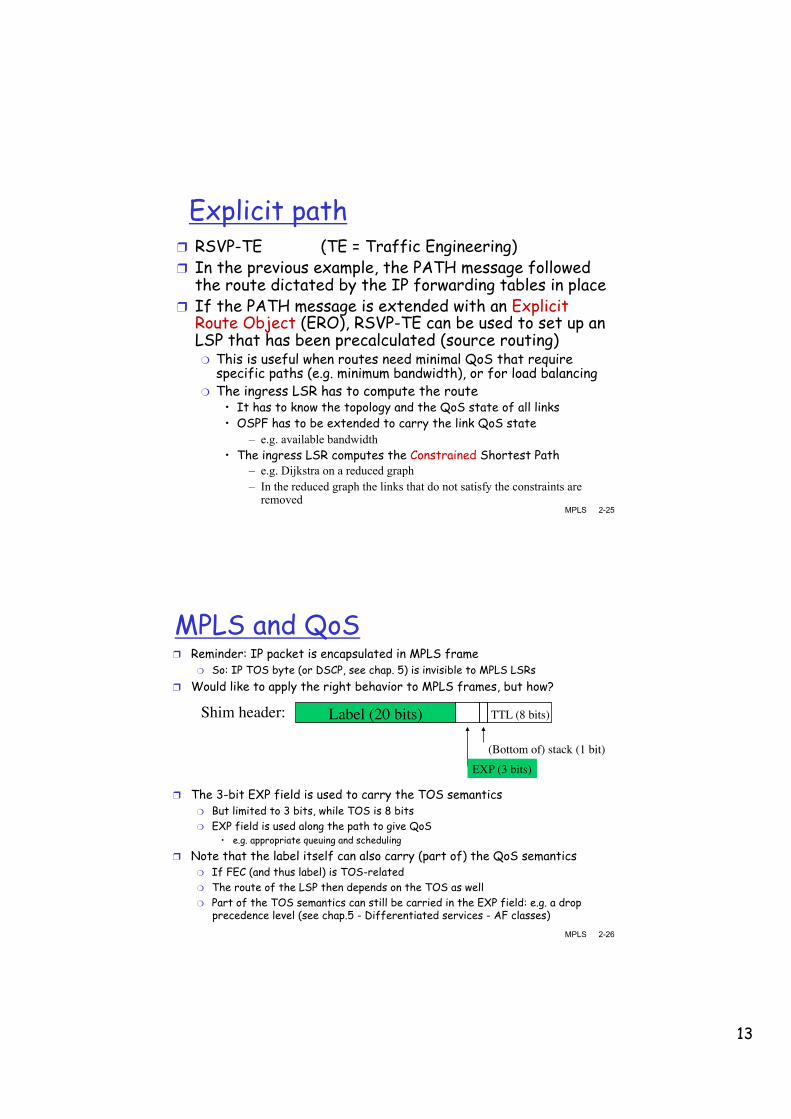
Explicit path ❒ RSVP-TE (TE = Traffic Engineering) ❒ In the previous example, the PATH message followed
the route dictated by the IP forwarding tables in place ❒ If the PATH message is extended with an Explicit
Route Object (ERO), RSVP-TE can be used to set up an LSP that has been precalculated (source routing) ❍ This is useful when routes need minimal QoS that require
specific paths (e.g. minimum bandwidth), or for load balancing ❍ The ingress LSR has to compute the route
• It has to know the topology and the QoS state of all links • OSPF has to be extended to carry the link QoS state
– e.g. available bandwidth • The ingress LSR computes the Constrained Shortest Path
– e.g. Dijkstra on a reduced graph – In the reduced graph the links that do not satisfy the constraints are
removed
© From Computer Networking, by Kurose&Ross MPLS 2-26
MPLS and QoS ❒ Reminder: IP packet is encapsulated in MPLS frame
❍ So: IP TOS byte (or DSCP, see chap. 5) is invisible to MPLS LSRs ❒ Would like to apply the right behavior to MPLS frames, but how?
Label (20 bits)Shim header: TTL (8 bits)
(Bottom of) stack (1 bit)EXP (3 bits)
❒ The 3-bit EXP field is used to carry the TOS semantics ❍ But limited to 3 bits, while TOS is 8 bits ❍ EXP field is used along the path to give QoS
• e.g. appropriate queuing and scheduling
❒ Note that the label itself can also carry (part of) the QoS semantics ❍ If FEC (and thus label) is TOS-related ❍ The route of the LSP then depends on the TOS as well ❍ Part of the TOS semantics can still be carried in the EXP field: e.g. a drop
precedence level (see chap.5 - Differentiated services - AF classes)

14
© From Computer Networking, by Kurose&Ross MPLS 2-27
MPLS and TTL
❒ MPLS TTL ❍ Allows to discard MPLS frames trapped in transient loops ❍ Allows the MPLS TTL to serve as hop count for the inner IP
packet ❒ Linking IP and MPLS TTLs:
❍ The IP TTL field is copied in the MPLS TTL field at ingress MPLS LSR
❍ The MPLS TTL is decremented by LSRs ❍ The egress MPLS LSR copies the MPLS TTL back in the IP
TTL ❍ Note: If MPLS TTL expires, LSR does not necessarily know
how to send the ICMP packet to the source!
Label (20 bits)Shim header: TTL (8 bits)
(Bottom of) stack (1 bit)EXP (3 bits)
© From Computer Networking, by Kurose&Ross MPLS 2-28
Chapter 2: MPLS
Overview ❒ Virtual Circuits (VC) - Reminder ❒ MPLS networks ❒ MPLS Virtual Private Networks (VPNs)
Chapter 6 of ACM SIGCOMM eBook on Recent Advances in Networking, 2013. http://www.sigcomm.org/content/ebook

15
© From Computer Networking, by Kurose&Ross MPLS 2-29
Virtual Private Networks (VPNs) ❒ Institutions often want private networks for security
❍ Costly! ❍ Need separate (private) routers, links, DNS infrastructure,…
❒ VPN: institution’s inter-office traffic is sent over public Internet instead ❍ As if dedicated physical connections would exist to interconnect
the remote customer equipments • But here only virtual links, also called pseudowires
❍ So, traffic is logically separate from other customers’ traffic ❍ Ideally traffic is also encrypted before entering public
Internet • But we won’t cover security in this chapter
© From Computer Networking, by Kurose&Ross MPLS 2-30
L3VPNs (Layer 3 VPNs) ❒ We will focus on the most popular L3VPNs (Layer 3 VPNs)
❒ Def.: a L3VPN transports layer 3 packets, namely IP packets
❒ So, a L3VPN is like establishing tunnels between remote customer IP routers
❒ Most L3VPNs are based on MPLS
❒ Other types of VPNs: ❍ L2VPNs carry layer 2 frames (e.g. Ethernet frames)
• Interconnected customer sites would form a single LAN • Single broadcast domain
❍ L1VPNs carry layer 1 symbols • For example, establishing light paths in an optical network

16
© From Computer Networking, by Kurose&Ross MPLS 2-31
An MPLS VPN with 2 customers
MPLS network with Label Switched Routers
(LSRs) in the core
IP-only Customer Edge (CE) router
MPLS-capable Provider Edge (PE) router, Label Edge Router (LER)
IP range allocated to this site of customer 1 (can overlap with IP addresses of another customer)
Two IP ranges allocated to customer 2
(some can be private)
© From Computer Networking, by Kurose&Ross MPLS 2-32
Looking inside the provider’s network ❒ It is both an MPLS
and an IP network ❒ All internal
interfaces also have IP addresses (here in the 80.0.0.0/8 range)
❒ There are 2 VPNs ❒ Packets destined
for a given CE router along a given path with a given QoS will belong to the same MPLS FEC
❒ The network has AS number 100 (for BGP)
❒ 80.0.0.0/8 is not announced outside of AS 100
LSR 1 and 2 are P routers LER 1, 2 and 3 are PE routers

17
© From Computer Networking, by Kurose&Ross MPLS 2-33
Three ingredients of an MPLS VPN ❒ Note first that:
❍ Customers may have overlapping addresses
• Thus a tunneling mechanism is needed
❍ Don’t want to manage manually O(n2) tunnels per VPN, when a customer has n sites
❍ Don’t want to update all the forwarding tables of the n PEs of a VPN when one customer adds a new subnet to one of its sites
❍ Would like (un)encapsulations to take place at the PEs, not the CEs. Easier for customers
❒ Three ingredients: ❍ 1. Achieve any-to-any IP
connectivity among PEs ❍ 2. Define signaling
mechanism to distribute customer prefixes between PEs
❍ 3. Define an encapsulation mechanism to transport packets from one PE to another PE across the network
© From Computer Networking, by Kurose&Ross MPLS 2-34
1. Any-to-any connectivity between PEs ❒ Assign a
loopback address (/32) to each PE, i.e., an address associated with a virtual interface, independent of the availability of specific network interfaces
❒ Let the IGP (e.g., OSPF) announce them to all P and PE routers
Loopback address

18
© From Computer Networking, by Kurose&Ross MPLS 2-35
Showing the resulting routing table of routers
Can also set IGP link weights to engineer traffic
© From Computer Networking, by Kurose&Ross MPLS 2-36
2. Use MP-BGP to distribute customer prefixes
❒ Customer prefixes are learned by PE on an eBGP session between PE and CE
❒ For the iBGP part, MPLS relies on Multi-Protocol BGP (MP-BGP)
❒ It supports multiple address families (IPv4 and IPv6) and additional information to identify VPN: the L3VPN identifier (i.e., the customer) See Route Distinguisher (RD) 8-byte field in MP-BGP messages
PE
CE CE
PE PE
CE

19
© From Computer Networking, by Kurose&Ross MPLS 2-37
3. Use MPLS encapsulation between PEs
❒ In its simplest form (i.e., each PE is a FEC) all P and PE routers run LDP to distribute label-to-PE mappings
❒ First attempt: ❍ At ingress PE, an IP
packet coming from a CE router is encapsulated in the suitable MPLS tunnel by pushing the MPLS label associated with the (loopback address of the) egress PE
❒ Finding the egress PE? ❍ Ingress PE knows the
incoming CE and therefore the L3VPN id
❍ Combined with the IP destination address, this L3VPN id gives the egress PE (thanks to MP-BPG)
❒ Egress PE pops the MPLS label and should forward the IP packet to the right CE… ❍ Any problem here?
© From Computer Networking, by Kurose&Ross MPLS 2-38
MPLS double encapsulation ❒ Problem is: ❒ If several CEs (from
distinct customers) are connected to the same PE, and if these CEs announce overlapping IP addresses, then the PE cannot determine the right CE, because the L3VPN id is not known!
❒ Solution: ❒ 1. Ingress PE first pushes an
inner label identifying the L3VPN (of ingress CE)
❒ 2. Ingress PE then pushes an outer label identifying the egress PE. This is the only label used (and swapped) by P routers to forward the MPLS frame
❒ 3. Egress PE pops outer label and reads inner label to determine the L3VPN
❒ 4. Egress PE pops inner label and forwards the IP packet to the right CE using the specific forwarding table of that VPN

20
© From Computer Networking, by Kurose&Ross MPLS 2-39
Optimizations
❒ Penultimate hop popping: ❍ The last P router can
already remove the outer label before forwarding the MPLS frame to the egress PE
❒ The Extranet case: i.e., interconnecting two VPNs (e.g., of different customers) that have non-overlapping IP address ranges ❍ Can avoid the creation
of several VPN-specific forwarding tables
❍ Consumes less router memory and CPU time
© From Computer Networking, by Kurose&Ross MPLS 2-40
Chapter 2: Summary ❒ MPLS
❍ Adding virtual circuits to (or “under”) IP
❍ Label switching • Associates a label with a
FEC (flexible mapping) ❍ Need additional signaling
protocols to distribute label bindings
• e.g., LDP, RSVP ❍ IP routing protocols (e.g.
OSPF, BGP) still used to distribute topology info and prefixes
❍ Routing functionality extended with RSVP-TE
❒ MPLS-VPN ❍ 3 ingredients:
• PE connectivity • MP-BGP distribution, • MPLS tunnelling
❍ Customers unaware of MPLS-specific details
• Can keep their IP addressing plan
❍ Traffic from different customers share same MPLS tunnels but correctly demultiplexed at egress PE
❍ Scalable: configuration of P routers only dependent on # of PEs, but independent from # of VPNs, # of CEs, # of IP prefixes