computer peripherals - ian mcloughlin. barcode 2 digit. ... book records can now be kept in a...
TRANSCRIPT

Computer Peripherals
School of Computer Engineering
Nanyang Technological University
Singapore
These notes are part of a 3rd year undergraduate course called "Computer Peripherals", taught at Nanyang Technological University
School of Computer Engineering in Singapore, and developed by Associate Professor Kwoh Chee Keong. The course covered
various topics relevant to modern computers (at that time), such as displays, buses, printers, keyboards, storage devices etc... The
course is no longer running, but these notes have been provided courtesy of him although the material has been compiled from
various sources and various people. I do not claim any copyright or ownership of this work; third parties downloading the material
agree to not assert any copyright on the material. If you use this for any commercial purpose, I hope you would remember where you
found it.
Further reading is suggested at the end of each chapter, however you are recommended to consider a much more modern alternative
reference text as follows:
Computer Architecture: an embedded approach Ian McLoughlin
McGraw-Hill 2011
Chapter 6. Bar codes
6.1 Introduction
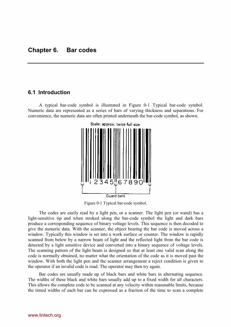
A typical bar-code symbol is illustrated in Figure 0-1 Typical bar-code symbol.Numeric data are represented as a series of bars of varying thickness and separations. Forconvenience, the numeric data are often printed underneath the bar-code symbol, as shown.
Figure 0-1 Typical bar-code symbol.
The codes are easily read by a light pen, or a scanner. The light pen (or wand) has alight-sensitive tip and when stroked along the bar-code symbol the light and dark barsproduce a corresponding sequence of binary voltage levels. This sequence is then decoded togive the numeric data. With the scanner, the object bearing the bar code is moved across awindow. Typically this window is set into a work surface or counter. The window is rapidlyscanned from below by a narrow beam of light and the reflected light from the bar code isdetected by a light sensitive device and converted into a binary sequence of voltage levels.The scanning pattern of the light beam is designed so that at least one valid scan along thecode is normally obtained, no matter what the orientation of the code as it is moved past thewindow. With both the light pen and the scanner arrangement a reject condition is given tothe operator if an invalid code is read. The operator may then try again.
Bar codes are usually made up of black bars and white bars in alternating sequence.The widths of these black and white bars usually add up to a fixed width for all characters.This allows the complete code to be scanned at any velocity within reasonable limits, becausethe timed widths of each bar can be expressed as a fraction of the time to scan a complete
www.lintech.org

Barcode 2
digit. These fractions are relatively independent of velocity provided the scan velocity doesnot change significantly in the course of a scan.
6.2 Applications
One application of bar codes is in article numbering in supermarkets and other retailingoperations. This can be useful at the point of sale, stock room or warehouse. The articleidentity can be quickly conveyed to a computer. Various improvements in efficiency of theretailing operation can thereby be obtained, such as an automatic update of stock levels,automatic re-ordering of new stock, better marketing information, and the ability to carryreduced levels of stock because of quicker replenishment of stock. This book carries a barcode on the rear outside cover. Bar codes are also used in library systems. Each book islabelled with a unique bar code which is read when the book is issued and returned. Thiseliminates the form filling and record keeping normally associated with these operations.Book records can now be kept in a computer data base, which permits automatic productionof overdue-book notifications, generation of statistics, and other benefits. Other applicationsof bar codes include control of the dispensing of drugs within a hospital.
6.3 Symbologies
A bar code symbol is a parallel arrangement of varying width bars and spaces."Symbology" is the term used to describe the unambiguous rules specifying the way that datais encoded into the bar and space widths.
Symbology is analogous to language. When humans communicate via the spoken orwritten word, any language can be used provided that both parties agree to and are proficientin the choice. The same concept follows in bar code: depending on the data to becommunicated, several different symbologies can be used. Communication obviously cannotoccur unless the readings and printing equipment use a compatible symbology. This is animportant consideration because dozens of different bar code symbologies have beendeveloped since the technology's inception in the late 1940s.
6.3.1 Characteristics of a Symbology
6.3.1.1 Character SetThe term "character set" describes the range of data characters that can be encoded into
a given symbology. Some symbologies can encode only numbers and are therefore termed"numeric" symbologies. Other symbologies can encode alphanumeric information, whileothers support the entire 128 unique codes of the ASCII character set.
6.3.1.2 Symbology TypeBar code symbologies fall into two general categories: discrete and continuous.
In a discrete code, each character can stand alone and can be decoded independentlyfrom the adjacent characters. Each character is separated from its neighbour by looselytoleranced intercharacter gaps, which contain no information. Every character has a bar oneach end. In the decoding process, each character is treated individually. See Figure 3.1.2.1.
www.lintech.org

Barcode 3
Figure 0-2 : Discrete Symbology.
Because the intercharacter gaps are loosely toleranced, a discrete code can be printedby a variety of different techniques. A discrete code can easily be produced by a printer thatprints an entire character at one time, such as a movable font device.
A continuous code has no intercharacter gaps. Every character starts with a bar andends with a space or vice versa, as shown in Figure 0-3 : Continuous Symbology. The end ofone character is indicated by the start of the next character.
Figure 0-3 : Continuous Symbology.
In a continuous bar code symbology there are no intercharacter gaps. Every characterbegins with a bar and ends with a space. Some form of termination pattern starting with a barmust provide the last “edge of next character” for the symbol's last character.
Since there are no intercharacter gaps, a continuous code requires less symbol length toencode a given amount of data. Offsetting this density advantage is the fact that the range ofavailable demand printing technologies is more restricted for continuous codes than it is fordiscrete symbologies.
6.3.1.3 Number of Element WidthsIn a bar code symbol, data is conveyed in the widths of the bars and spaces. Two basic
types of bar codes exist: those that employ only two element widths (wide and narrow), andthose that employ multiple widths.
www.lintech.org
Barcode 4
In a two-width symbology, the ratio between wide and narrow element widths is calledN. N is typically allowed to vary over some range (usually from 2.0 to 3.0), but must beconstant for a given symbol. As N gets larger, the allowable printing tolerance also increases.
In a multiple-width symbology, bars and spaces can assume several different widthvalues. Most multiple-width symbologies are modular, meaning that the length of a characteris subdivided into a predetermined number of modules, and a bar or space width is always anintegral number of modules. Multiple-width symbologies are usually continuous and areoften decoded using edge-to-similar-edge algorithms. This technique involves themeasurement of distances between similar edges of adjacent elements rather than themeasurement of actual element widths.
Continuous codes with multiple element widths are often called (n,k) codes, where nrefers to the number of modules in a character width and k to the number of bars (andspaces). The total number of possible patterns in an (n,k) code can be determined from theexpression:
(n - l)!(2k -1)! (n - 2k)!
6.3.1.4 Fixed or Variable LengthSome symbologies by their very structure encode only messages of a fixed length.
Other symbologies should only be used in a fixed length environment because of datasecurity considerations, while other symbologies can be used to encode true variable lengthdata.
6.3.1.5 DensityBar code symbologies differ in the amount of data that can be encoded in a given unit
of length. In order to allow meaningful comparisons, the value of X (width of a narrow bar orspace) needs to be considered when examining relative densities.
Note that density is normally specified only for the data characters. The overall lengthof a symbol needs to include start/stop characters, quiet zones, and any check characters.
6.3.1.6 XX is the term used to describe the nominal width of a bar code symbol's narrow
elements (both bars and spaces). It is often calculated as the average width of the symbol'snarrow elements and by convention is expressed in mils (thousandths of an inch).
6.3.1.7 Self CheckingA symbology is termed self-checking if a single printing defect will not cause a
character to be transposed into another valid character in the same symbology.
6.3.2 Classification on Barcode Symbologies
6.3.2.1 Numeric-only barcodes1. Code 11
2. Interleaved 2 of 5
www.lintech.org

Barcode 5
3. Industrial 2 of 5
4. Standard 2 of 5
5. Codabar
6. Plessey
7. MSI
8. Postnet
6.3.2.2 Retail barcodes1. EAN-8
2. EAN-13
3. UPC-A
4. UPC-E
6.3.2.3 Alphanumeric barcodes1. Code 39
2. Code 93
3. Code 128
4. LOGMARS
6.3.2.4 2-Dimensional barcodes1. PDF417
2. DataMatrix
3. Data Code
4. Maxicode
5. Code 49
6. 16K
6.4 UPC
An American format, used for article numbering, is that of the universal product code(UPC). One version of the UPC is:
Sxxxxx xxxxxC | | | +----------- (check digit) | | +---------------- (product number) | +------------------------ (manufacturer number)+---------------------------- (number-system character).
The manufacturer and product numbers occupy respectively the left and right halves ofthe symbol. The numbers are also printed underneath the symbol.
www.lintech.org
Barcode 6
The number-system character identifies the symbol version and also the type of article.The check digit is used to detect errors. The check digit and number-system character are notprinted underneath the symbol.
The Universal Product Code (UPC) has been successfully employed in the supermarketindustry since 1973. UPC is a coding system as well as a symbology; it is designed touniquely identify a product and its manufacturer.
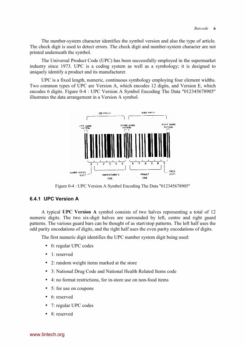
UPC is a fixed length, numeric, continuous symbology employing four element widths.Two common types of UPC are Version A, which encodes 12 digits, and Version E, whichencodes 6 digits. Figure 0-4 : UPC Version A Symbol Encoding The Data "012345678905"illustrates the data arrangement in a Version A symbol.
Figure 0-4 : UPC Version A Symbol Encoding The Data "012345678905"
6.4.1 UPC Version A
A typical UPC Version A symbol consists of two halves representing a total of 12numeric digits. The two six-digit halves are surrounded by left, centre and right guardpatterns. The various guard bars can be thought of as start/stop patterns. The left half uses theodd parity encodations of digits, and the right half uses the even parity encodations of digits.
The first numeric digit identifies the UPC number system digit being used:
• 0: regular UPC codes
• 1: reserved
• 2: random weight items marked at the store
• 3: National Drug Code and National Health Related Items code
• 4: no format restrictions, for in-store use on non-food items
• 5: for use on coupons
• 6: reserved
• 7: regular UPC codes
• 8: reserved
www.lintech.org
Barcode 7
• 9: reservedThe next group of 5 digits identifies the manufacturer (the manufacturer’s code). This
number is assigned by the Uniform Code Council (UCC). The first five digits of the right halfof the pattern are the product code digits and are assigned by the manufacturer, and the finaldigit is a Modulo 10 checksum check digit used for error detection. The check digit whosevalue is evaluated mathematically based on all of the other numbers encoded in the symbol.A weighting scheme is used in its calculation, so that the check digit also protects againsttransposition errors if the data is manually entered. Although UPC is a continuous symbologythe left and right halves of the pattern can be independently decoded.
6.4.1.1 Modulo-10 checksumThe UPC bar code standard incorporates a modulo-10 error check character, which
needs to be taken into account in the data recovery software. The modulo-10 algorithm is asfollows:
1. Add the values of the digits in odd positions 1, 3, 5, 7, 9, and 11 to S1.
2. Multiply this result by 3: S2 = S1 X 3.
3. Add the values of the digits in even positions 2, 4, 6, 8, and 10 to S3.
4. Sum the results of steps 2 and 3: S4 = S3 + S2.
5. The check character is the smallest number which, when added to the result in step4, produces a multiple of 10: Check Digit = 10 - Remainder ( S4/10 )
Example: Assume the barcode data = 01234567890
1. 0 + 2 + 4 + 6 + 8 + 0 = 20
2. 20 X 3 = 60
3. 1 + 3 + 5 + 7 + 9 = 25
4. 60 + 25 = 85
5. 85 + X = 90 (next highest multiple of 10), therefore X = 5 (checksum)
A UPC-A code may be augmented with a 2-digit or 5-digit extension. These extensionsare handled as separate barcodes and are generally used to create ISBN's (InternationalStandard Book Numbers).
The UPC-A data is encoded as two bars and two spaces in a character that is sevenmodules wide. It is a (7,2) code, which has 20 unique patterns. Bar and space widths may be1, 2, 3, or 4 modules wide. Figure 0-5 illustrates the pattern for "6" encoded for either the leftor right half of the symbol.
www.lintech.org

Barcode 8
Figure 0-5 : UPC version A Encodation of the Digit “6”.
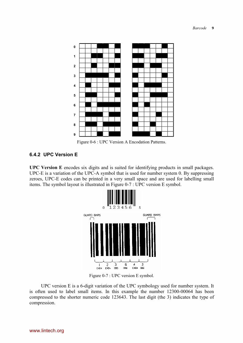
Encodation differs for the left and right halves of the symbol, as shown in Figure 0-6 :UPC Version A Encodation Patterns. Note that the term "parity" refers to whether the sum ofthe bar module widths in a given character is an even or an odd number.
Because the bar height of either half of a UPC Version A symbol is greater than thewidth of the six digits, omnidirectional scanning is possible if orthogonal scanning lines areemployed. The scanner can independently decode the right and left halves of the symbolbecause an examination of the data's parity indicates which half was decoded. The guard barsare usually printed with greater length than other bars in the symbol. This is done tomaximise the allowable scanning tilt angle.
www.lintech.org
Barcode 9
0
1
2
3
4
5
6
7
8
9
Figure 0-6 : UPC Version A Encodation Patterns.
6.4.2 UPC Version E
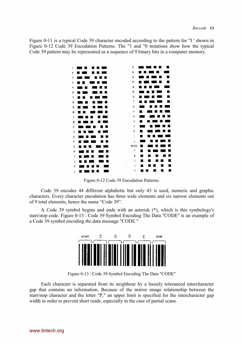
UPC Version E encodes six digits and is suited for identifying products in small packages.UPC-E is a variation of the UPC-A symbol that is used for number system 0. By suppressingzeroes, UPC-E codes can be printed in a very small space and are used for labelling smallitems. The symbol layout is illustrated in Figure 0-7 : UPC version E symbol.
Figure 0-7 : UPC version E symbol.
UPC version E is a 6-digit variation of the UPC symbology used for number system. Itis often used to label small items. In this example the number 12300-00064 has beencompressed to the shorter numeric code 123643. The last digit (the 3) indicates the type ofcompression.
www.lintech.org

Barcode 10
In addition to the requirement that the first digit of the barcode (number system) mustbe zero, there are four rules that determine what UPC codes can be printed using thecompressed UPC-E format:
• If the last 3 digits of the manufacturer's number are 000, 100, or 200, the validproduct code numbers are 00000 - 00999 (1,000 numbers).
• If the last 3 digits of the manufacturer's number are 300, 400, 500, 600, 700, 800, or900, the valid product code numbers are 00000 - 00099 (100 numbers).
• If the last 2 digits in the manufacturer's number are 10, 20, 30, 40, 50, 60, 70, 80, or90, the valid product code numbers are 00000 - 00009 (10 numbers).
• If the manufacturer's number does not end in zero, the valid product code numbersare 00005 - 00009 (5 numbers).
Guard bars precede and follow the data in the pattern. The parity of the encodationfollows the pattern shown. Because of the data compression process used, version E symbolis often referred to as a zero-suppressed symbol
The six digits are enclosed between two left-hand guard bars and three right hand guardbars. A symbol check character is encoded into the parity of the six data digits. Of the sixdigits, three have even parity and three have odd parity.
The nominal X dimension employed in all UPC symbols is 13 mils. An allowablemagnification factor of 0.8 to 2.0 results in a range of printable X values between 10.4 and 26mils.
6.5 EAN
6.5.1 IMPORTANT NOTE
On June 9, 1997 the Uniform Code Council announced that January 1, 2005 will be the'sunset date' for expansion of UPC to EAN-13 (known as UPC-13 in the USA). Thisexpansion is designed to provide a larger pool of numbers for US manufacturers and toeliminate the need for manufacturers who export goods to the US and Canada to double-labeltheir products.
Most scanners sold as early as 1985 can auto-discriminate between these two codes, sothe hardware will generally not be an issue. The primary concern is that product databasesused by retailers will need to accommodate all EAN numbers; many database designscurrently store only 12 digits. In order to guard against any confusion between an existingUPC code, a new UPC-13 code, and a previously assigned EAN-13 code it is necessary touse all 13 digits as a lookup key.
6.5.2 EAN codes
The European Article Numbering system (abbreviated as EAN) is a superset of UPC.An EAN scanner can decode UPC, but the inverse is, unfortunately not necessarily true.
The European article number (EAN) system includes a two-digit code which identifiesthe country, and is designed to be compatible with the American UPC.
www.lintech.org

Barcode 11
EAN has two versions: EAN-13 and EAN-8, encoding 13 and 8 digits respectively. AnEAN-13 symbol contains the same number of bars as UPC Version A, but encodes athirteenth digit into a parity pattern of the left-hand six digits. This thirteenth digit, incombination with the twelfth digit, defines two flag characters that represent a country code.For compatibility with UPC, flags 00, 01, 03, 04, and 06 through 09 are assigned to the U.S.
6.5.2.1 EAN-13 codeEAN-13 is used world-wide for marking retail goods. It encodes 13 characters: the first
two are a country code, followed by 10 data digits and a checksum. 2-digit and 5-digitsupplemental barcodes may be added for a total of 14 or 17 data digits. Similar to UPC, thechecksum is a Modulo 10 calculation:
1. Add the values of the digits in the even-numbered positions: 2, 4, 6, etc.
2. Multiply this result by 3.
3. Add the values of the digits in the odd-numbered positions: 1, 2, 5, etc.
4. Sum the results of steps 2 and 3.
5. The check character is the smallest number which, when added to the result in step4, produces a multiple of 10.
Example: Assume the barcode data = 123456789012
1. 2 + 4 + 6 + 8 + 0 + 2 = 22
2. 22 * 3 = 66
3. 1 + 3 + 5 + 7 + 9 + 1 = 26
4. 78 + 22 = 92
5. 92 + X = 100 (nearest equal or higher multiple of 10), therefore X =
8 (checksum)
Figure 0-8 EAN-13
6.5.2.2 EAN-8EAN-8 is a shortened version of the EAN-13 code. An EAN-8 symbol has a left-hand
guard pattern, four odd parity digits, a centre guard pattern, four even parity digits, and aright-hand guard pattern. An EAN-8 symbol encodes two flag digits (2-digit country code),five data digits, and one check digit. An EAN-8 symbol is shown in Figure 0-9 : EAN 8Symbol Encoding the Data "4015347." 2-digit and 5-digit extension barcodes may be added.
www.lintech.org

Barcode 12
Figure 0-9 : EAN 8 Symbol Encoding the Data "4015347."
Figure 0-10 EAN-8
UPC/EAN has proven to be extremely successful in the retail marketplace. In normalusage, every code from a supermarket scanner is verified against an in store computer'sdatabase before being acted upon. In this mode, very high data security has been reliablydemonstrated.
6.6 Code 39
Code 39 was the first alphanumeric symbology to be developed. Code 39 is widelyused in many industries and is the standard for many goverment barcode specifications,including the U.S. Department of Defense. Code 39 is defined in American NationalStandards Institute (ANSI) standard MH10.8M-1983, and is also known as USD-3 and 3 of9.It is now the 'de facto' non-retail symbology. It is a discrete, two widths, selfchecking,variable length symbology that can readily be printed by a variety of technologies.
Every Code 39 character has five bars and four spaces. Of these nine elements, 3 arewide and 6 are narrow.
Figure 0-11 : Code 39 Character "I."
www.lintech.org
Barcode 13
Figure 0-11 is a typical Code 39 character encoded according to the pattern for "I ' shown inFigure 0-12 Code 39 Encodation Patterns. The "1 and "0 notations show how the typicalCode 39 pattern may be represented as a sequence of 9 binary bits in a computer memory.
Figure 0-12 Code 39 Encodation Patterns.
Code 39 encodes 44 different alphabetic but only 43 is used, numeric and graphiccharacters. Every character encodation has three wide elements and six narrow elements outof 9 total elements, hence the name “Code 39”.
A Code 39 symbol begins and ends with an asterisk (*), which is this symbology'sstart/stop code. Figure 0-13 : Code 39 Symbol Encoding The Data "CODE" is an example ofa Code 39 symbol encoding the data message "CODE."
Figure 0-13 : Code 39 Symbol Encoding The Data "CODE"
Each character is separated from its neighbour by a loosely toleranced intercharactergap that contains no information. Because of the mirror image relationship between thestart/stop character and the letter "P," an upper limit is specified for the intercharacter gapwidth in order to prevent short reads, especially in the case of partial scans.
www.lintech.org

Barcode 14
Although there are only 43 data characters in Code 39's character set, it is possible toencode all 128 ASCII characters using Code 39's Full ASCII feature. If a reader is in its FullASCII mode, the symbols $, /, %, and + are used as precedence codes with the 26 letters.
Breaking up long bar code messages into two or more shorter symbols for ease ofreading is sometimes advantageous. If the first data character of a Code 39 symbol is a space,the bar code reader appends the information contained within the symbol (excluding theleading space) to its buffer. This operation continues for all symbols that contain a leadingspace. When a Code 39 symbol is read that does not contain a leading space, the data isappended to the reader's buffer, and the entire buffer is transmitted and cleared for new data.
Code 39 is self-checking (a single printing defect cannot cause a substitution error) andis normally not used with a check character. An optional modulo 43 check character isdefined for use in specific applications that require exceptional data security. As a generalpolicy, the use of Code 39's check character is encouraged, especially if the print quality isless than optimum.
6.6.1 Code 39 Specification
Code 39 is a discrete, variable length, self-checking, alphanumeric symbologyemploying two-element widths. Every character has five bars and four spaces; three of theelements in any given character are wide, and six are narrow. Every symbol starts and endswith a unique start/stop character. A summary of Code 39's main characteristics is as follows:
♦ Character Set: 26 uppercase letters, 10 digits, 7 special characters; Extendable to full 128ASCII character set using a two-character precedence code scheme.
♦ Symbol Length: Variable
♦ Check Characters: Optional
♦ Overhead Characters: 2 per symbol
♦ Other Features: Concatenation ability
♦ Density: Maximum of 9.8 characters per inch when printed using a 7.5 mil X dimensionCode 39 Symbol Description Each
6.6.2 Code 39 Symbol Description:
Code 39 symbol consists of:
♦ Leading quiet zone
♦ Start character
♦ Data characters
♦ Stop character
♦ Trailing quiet zoneFigure 0-13 : Code 39 Symbol Encoding The Data "CODE" illustrates a typical Code
39 symbol.
6.6.3 Code 39 Encodation
www.lintech.org

Barcode 15
Each Code 39 character consists of five bars and the four intervening spaces; three ofthe nine elements are wide, and 6 are narrow. Each character has either two or zero wide bars.Figure 0-12 Code 39 Encodation Patterns. shows the encodation of bar and space pattems foreach character code. The asterisk character is exclusively used as a start/stop code.
6.6.4 Code 39 Dimensions
The minimum value of X is 7.5 mils for symbols used in open systems. X shall beconstant throughout a symbol.
The ratio of the nominal-wide element width to the nominal narrow-element width isdesignated as N and must remain constant throughout a symbol. The allowable range of N is2.0 to 3.0, but N must exceed 2.2 if X is less than 20 mils.
The minimum width of the intercharacter gap is (X - t), where t is the applicableprinting tolerance and the maximum is:
♦ 5.3X for values of X less than 10 mils
♦ 3X or 53 mils (whichever is greater) for values of X equal to or greater than 10 milsFor open systems, the minimum bar height is 15 percent of the symbol length or 0.25
inches, whichever is greater. The minimum quiet zone width is 10X. For optimum hand-scanning, the quiet zone width should be at least 0.25 inches. The overal1 length of a Code 39symbol is a function of X, N, the intercharacter gap width, and the number of data characters,as given by:
L = (C+2) (3N+6) X+(C + 1) I
where
L = length of symbol, excluding quiet zones
C = number of data characters
X = X dimension
N = wide-to-narrow ratio
I = intercharacter gap width
Many printers generate symbols with an intercharacter gap width of X. In this case, theexpression for symbol length can be simplified to
L = ((C + 2) (3N + 7) - 1) X
6.6.5 Code 39 Dimensional Tolerances
The allowable printing width tolerances are given by the expression
t 427
N 23
X= ± −
where
t = the allowable width deviation about the nominal dimension of a given element
X = X dimension
www.lintech.org
Barcode 16
N - wide-to-narrow ratio
The tolerance t applies to the printed width of all elements, both wide and narrow.These tolerances should not accumulate within a single character. The overall character widthshall not deviate from nominal by more than 2t.
For measuring purposes, the edge of a bar/space transition is defined as the centre of acircular sampling aperture of diameter no greater than 0.8X when the apparent reflectance ofthe sample viewed through the aperture is halfway between the maximum and minimumreflectance obtained by that aperture on the adjacent bar and space.
6.6.6 Code 39 Optical Properties
Reflectivity measurements are made at a wavelength of 633 manometers withilluminating and viewing axes separated by 45 degrees, with one of the axes positionedperpendicular to the sample surface. The aperture of each of the two optical systems shouldsubtend an angle of no more than 15 degrees. The measured diffuse reflectance is defined asthe ratio of the light reflected from the sample to that reflected from a specially preparedMagnesium Oxide or Barium Sulphate standard measured under the same conditions. One ofthe optical paths must restrict the sample field to an area equal to that of a circle of 0.8X, andthe other path's sample field must have an area greater than that of a circle of 8X.
The maximum bar reflectance is 30 percent. The minimum space reflectance is 25percent.
The minimum reflectance difference (MRD) is equal to the reflectivity differencebetween the darkest space and the lightest bar. The minimum value of MRD is 37.5 percent ifX is less than 40 mils, and 20 percent if X is equal to or greater than 40 mils.
6.6.7 Code 39 Full ASCII Mode
If suitably programmed, a Code 39 reader can decode the 128 ASCII character set byusing paired character sequences made up of the character $, ., %, or / followed by one of the26 letters, as shown in Table 1 CODE 39 ASCII chart.
www.lintech.org

Barcode 17
Table 1 CODE 39 ASCII chart
CODE 39 ASCII CHARTASCII CODE ASCII CODE ASCII CODE ASCII CODE
NUL %U SP SPACE @ %V ` %
SOH $A ! /A A A a +A
STX $B “ /B B B b +B
ETX $C # /C C C c +C
EOT $D $ /D D D d +D
ENQ $E % /E E E e +E
ACK $F & /F F F f +F
BEL $G ‘ /G G G g +G
BS $H ( /H H H h +H
HT $I ) /I I I i +I
LF $J * /J J J j +J
VT $K + /K K K k +K
FF $L ’ /L L L l +L
CR $M - - M M m +M
SO $N . . N N n +N
SI $O / /O O O o +O
DLE $P 0 0 P P p +P
DC1 $Q 1 1 Q Q q +Q
DC2 $R 2 2 R R r +R
DC3 $S 3 3 S S s +S
DC4 $T 4 4 T T t +T
NAK $U 5 5 U U u +U
SYN $V 6 6 V V v +V
ETB $W 7 7 W W w +W
CAN $X 8 8 X X x +X
EM $Y 9 9 Y Y y +Y
SUB $Z : /Z Z Z z +Z
ESC %A ; %F [ %K { %P
FS %B < %G \ %L | %Q
GS %C = %H ] %M } %R
RS %D > %I ^ %N ~ %S
US %E ? %J _ %O DEL %T,%X,%Y,%Z
Note: Character pairs /M and /N decide as a minus sign and a period respectively.Character pairs /P through /Y decode as the digit 0 through 9.
6.6.8 Code 39 Check Character
www.lintech.org

Barcode 18
An optional check character is defined for Code 39 applications requiring higher levels ofdata security. When used, the check character is positioned between the final data characterand the stop character. The check character is determined as follows:
Table 2 Code 39 Character set
Character Value Character Value
0 0 M 22
1 1 N 23
2 2 O 24
3 3 P 25
4 4 Q 26
5 5 R 27
6 6 S 28
7 7 T 29
8 8 U 30
9 9 V 31
A 10 W 32
B 11 X 33
C 12 Y 34
D 13 Z 35
E 14 _ 36
F 15 . 37
G 16 SPACE 38
H 17 $ 39
I 18 / 40
J 19 + 41
K 20 % 42
L 21
♦ Using Table 2 Code 39 Character set. determine the numerical value of each of the datacharacters.
♦ Sum the values of all the data characters.
♦ Find the modulo 43 remainder of the sum from above.
♦ The check character is that character whose value from Table 1 CODE 39 ASCII chart isequal to the remainder.
As an example, if the data characters are “TEST”, the values would be summed as29+14+28+29=100. 43 goes into 100 twice, with a remainder of 14. The letter “E” has avalue of 14 is therefore the check character.
6.6.9 Code 39 Symbol Concatenation
www.lintech.org

Barcode 19
It is sometimes advantageous to break up long messages into multiple, shorter symbols.If the first data character of a Code 39 symbol is a space, the reader may be programmed toappend the information contained in the remainder of the symbol to a storage buffer (data nottransmitted). This operation continues for all successive symbols with a leading space, withmessages being added to the end of previously stored messages. When a message is readwhich does not contain a leading space, the contents are appended to the buffer, the entirebuffer is transmitted, and the buffer is cleared.
6.6.10 Code 39 Dimensional Verification
The following procedure should be used to determine if a Code 39 symbol meets thespecified dimensional tolerances:
1. Measure and record the perceived width for every element, the intercharacter gaps, andthe two quiet zones.
2. Decode the symbol, confirming that there are valid start, stop, and data characters.
3. As determined by decoding, sort the widths of all the characters' elements (excludingintercharacter gaps and quiet zones) into four groups: narrow bars, narrow spaces, widebars, and wide spaces.
4. If it is desired to evaluate symbol quality against values of X and N specified in anapplication standard, those values can be used directly in step 9, skipping steps 5through 8.
5. Compute the average width in each group:
ANB = average narrow bar
ANS = average narrow space
AWB = average wide bar
AWS = average wide space
6. Compute X as follows:
2ANSANBX +
=
7. Compute N as follows:
2XAWSAWBN +
=
8. Confirm that X and N are within allowed ranges:
a. Check that X is greater than or equal to 0.0075”; if not, declare X =0.0075”.
b. Check that N is greater than or equal to 2.0; if not, declare N = 2.0.
c. If X is less than 0.020”, then check that N is greater than or equal to 2.2; if not,declare either X = 0.020”or N = 2.2.
d. Check that N is less than or equal to 3.0; if not, declare N = 3.0.
www.lintech.org

Barcode 20
9. Compute the printing tolerance:
t 427
N 23
X= ± −
10. Confirm that all measured widths fall within allowed limits, otherwise the symbol is notin conformance:
a. Check that all narrow elements fall within X - t to X + t.
b. Check that all wide elements fall within NX - t to NX + t.
If X or N were changed in step 8c, it might be necessary to use the opposite assumption inorder to meet the requirement that all the measured widths fall within the allowed limits.
11. Confirm that the sum of the widths of any number of adjacent elements within anycharacter does not deviate from nominal (using X and N as measured or assumedabove) by more than 2t, otherwise the symbol is not in conformance.
12. Confirm that all intercharacter gap widths (from step 1) are equal to or greater than X -t, otherwise the symbol is not in conformance.
13. If X is less than 10 mils, confirm that all intercharacter gaps are less than 5.3X,otherwise the symbol is not in conformance. If X is greater than or equal to 10 mils,confirm that all intercharacter gaps are less than 0.053" or 3X, whichever is greater,otherwise the symbol is not in conformance.
14. Confirm that each quiet zone is at least 10X wide, otherwise the symbol is not inconformance.
Note: In step 8a, the 7.5 mil limit is consistent with present practice for open systems. Inclosed applications, a lower limit may be used.
6.7 PDF-417
PDF-417 is a two-dimensional barcode which can store up to about 1,800 printableASCII characters or 1,100 binary characters per symbol. The symbol is rectangular; the shapeof the symbol can be adjusted to some extent by setting the width and allowing the height togrow with the data. It is also possible to break large amounts of data into several PDF-417symbols which are logically linked. There is no theoretical limit on the amount of data thatcan be stored in a group of PDF-417 symbols.
The capacity of PDF-417 can be helpful in applications where the data must travel withthe labelled item, where a host database is not always available for quick look-up. PDF-417 isbeing used for hazardous materials labelling; storing technical specifications and calibration
www.lintech.org

Barcode 21
data on electronic instruments; encoding fingerprints and photographs on the backs of drivers'licenses.
The maximum data density is determined by the smallest elements which can bereliably printed and scanned. Using the smallest recommended element size of 0.0075 inchwide and 0.010 inch high, the maximum data density in the binary mode is 686 bytes persquare inch (106.2 bytes per square centimetre). In the printable ASCII mode the density is1,144 characters per square inch (177.2 characters per square centimetre).
PDF-417 symbols require a 2-D scanner; they cannot be read using an ordinary linearbarcode scanner. A number of scanners are on the market using both laser and CCD cameratechnologies. PDF-417 symbols can be printed using most professional-grade thermaltransfer label printers on the market.
6.8 DataMatrix
DataMatrix is a two-dimensional barcode which can store from 1 to about 2,000characters. The symbol is square and can range from 0.001 inch per side up to 14 inches perside. As an example of density, 500 numeric only characters can be encoded in a 1-inchsquare using a 24-pin dot matrix printer. The sample shown above encodes 20 ASCIIcharacters.
DataMatrix is being used to encode product and serial number information on electricalrating plates; to mark of surgical instruments in Japan; to identify lenses, circuit boards, andother items during manufacturing.
DataMatrix symbols require a 2-D scanner; they cannot be read using an ordinary linearbarcode scanner. A number of scanners are on the market using both laser and CCD cameratechnologies. DataMatrix symbols can be printed using most professional-grade thermaltransfer label printers on the market.
6.9 BAR CODE READER
The bar codes are read either by holding the product stationary and passing a bar wandover the pattern, or alternatively by passing the product across an opening from which a lightbeam strikes the bar code. Figure 0-14 UPC scanner. shows this latter type of scanner, inwhich several laser light sources are directed in the general direction of the product, atdifferent orientations (typically a star pattern).
www.lintech.org

Barcode 22
Figure 0-14 UPC scanner.
In this manner, one of the laser beams will usually strike the bar code pattern as anangle suitable for reading; if none of the laser beams strike the bar code at a suitable angle,then the product is passed by the opening again until a successful read occurs. There is abackup procedure, in that repeated failures can always be rectified by entering the numericdata manually.
The bar code reader (wand or fixed scanner) will produce an asynchronous waveformoutput of widely varying and unknown data rate, in the range 0.2-20 cm/second. A zerooutput could either be an unwanted noise spike, or the beginning of an authentic scan. If itrepresents the beginning of a scan, then the total scan time will lie in the range 3-300milliseconds (11*0.033cm/scan rate).
At the commencement of the first LO to HI transition, a 'bar timing loop' is started, andat the next HI to LO transition, a 'space timing loop' is started. This procedure is repeated 30times, until 60 time intervals have been recorded (30 bars and 30 spaces), as indicated inFigure 0-16. The appropriate algorithm is shown in Figure 0-15.
Figure 0-15 Bar Code scan times
www.lintech.org
Barcode 23
SCAN FOR DATA RECOVERY
REPEAT: At First L -> H transition start BAR timing loop.
On Next H -> L transition start SPACE timing loop.
UNTIL : 59 Times (30 BARS & 29 SPACES) stored in memory.
Discarding times for guard bars, calculate total times for 12 digits and divide by 84to get average bit rate.
At middle of each bit period sense level to determine CHARACTER BITPATTERN.
Check parity to determine direction.
Do table look up to recover digit data.
Calculate Modulo-10 check digit and verify with recovered Check Digit.
Figure 0-16 Pseudo-code for UPC data recovery
Once 60 times have been stored in the table, they need to be converted first to barwidths, and then to bit patterns (digit information).
The per character scan rate will be fairly constant, so that the average time per module(black or white) will be one seventh of the total character scan time (since each character iscomprised of seven modules). The left, right and centre guard bands must be omitted frombar width calculations.
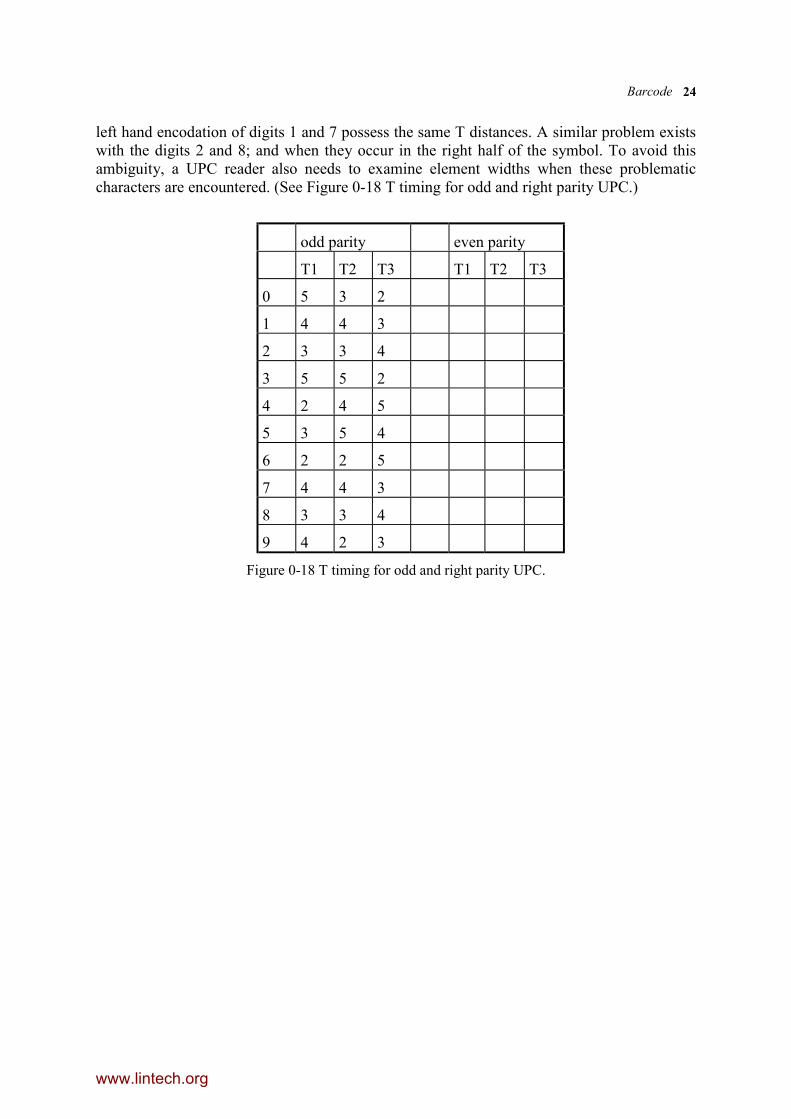
6.9.1 Edge-to-similar-edge algorithm
Figure 0-17 T distance in the edge-to-similar-edge algorithm
UPC is intended to be decoded using the edge-to-similar-edge algorithm. For eachcharacter, the first three timing T1, T2 and T3 are fixed in term of number of modules andT4 is dependent on the next character and hence not use in recognition. Unfortunately, the
www.lintech.org
Barcode 24
left hand encodation of digits 1 and 7 possess the same T distances. A similar problem existswith the digits 2 and 8; and when they occur in the right half of the symbol. To avoid thisambiguity, a UPC reader also needs to examine element widths when these problematiccharacters are encountered. (See Figure 0-18 T timing for odd and right parity UPC.)
odd parity even parity
T1 T2 T3 T1 T2 T3
0 5 3 2
1 4 4 3
2 3 3 4
3 5 5 2
4 2 4 5
5 3 5 4
6 2 2 5
7 4 4 3
8 3 3 4
9 4 2 3
Figure 0-18 T timing for odd and right parity UPC.
www.lintech.org