computerized embroidery machine · becs-a88/c88 computerized embroidery machine owner’s manual 1...
TRANSCRIPT
Version:2007-02
Computerized Embroidery Machine
B E C S –A88/C88
Owner's Manual

Index
BECS-A88/C88 computerized embroidery machine owner’s manual I
Index
Chapter 1 General Descriptions ................................................................................. 1
1-1 Warnings and Cautions................................................................................................ 1
1-2 The difference between A88 and C88.......................................................................... 3
1-3 Main Features.............................................................................................................. 3
1-4 Technical Specifications.............................................................................................. 8
Chapter 2 Operation Instruction .............................................................................. 10
2-1 Configuration and Direction of the Control Panel ...................................................... 10
2-2 Instruction of Control Panel....................................................................................... 11
2-3 Instruction of the Main Screen................................................................................... 12
2-4 Notes on Menu State............................................................................................ 19
2-5 Flow Chart of Embroidery......................................................................................... 19
2-6 Normal Embroidery, Returning and Patching ............................................................ 30
2-7 Operation Bar and Turn Shaft Button ........................................................................ 31
2-8 Patching Switch......................................................................................................... 31
2-9 System's Working Statuses........................................................................................ 32
Chapter 3 Disk Management..................................................................................... 34
3-1 Disk Choosing........................................................................................................... 34
3-2 Select One or Several Designs................................................................................... 37
3-3 Design Preview ......................................................................................................... 39
3-4 Design input.............................................................................................................. 40
3-5 Design Output ........................................................................................................... 42

Index
II BECS-A88/C88 computerized embroidery machine owner’s manual
3-6 Folder Operation........................................................................................................44
3-7 Formatting a Disk ......................................................................................................44
3-8 Deleting Objects in Disk (Including Design Files and Folders) ..................................45
3-9 Creating a New Folder in the Current Folder..............................................................46
Chapter 4 Common Parameters and Color-changing Order ........................48
4-1 Normal Parameters ....................................................................................................48
4.1.1 Setting “X&Y Scales” .............................................................................................................. 49 4.1.2 Setting of “Rotate” ................................................................................................................... 51 4.1.3 Setting of “Direction”............................................................................................................... 51 4.1.4 “Prior Mode” ............................................................................................................................ 51 4.1.5 “Rep. Mode”............................................................................................................................. 51 4.1.6 “Rep. Prior” .............................................................................................................................. 52 4.1.7 “X&Y Reps” ............................................................................................................................ 52 4.1.8 “X&Y Interval” ........................................................................................................................ 52
4-2 Setting of Color-changing order.................................................................................53
4.2.1 Color-changing Screen ............................................................................................................. 53 4.2.2 Setting of the color-changing order .......................................................................................... 54 4.2.3 Setting Needle Color ................................................................................................................ 56 4.2.4 Interchanging of Needle Colors................................................................................................ 57
Chapter 5 Setting General Parameters...................................................................58
5-1 Setting Procedure for General Parameters ..................................................................59
5-2 Introduction of Some Functions of General Parameters..............................................62
5.2.1 Cyclic Embroidery ............................................................................................................ 62 5.2.2 Store Manual Color-changing ........................................................................................... 63 5.2.3 Brake Adjustment (A Must for New Machine) ................................................................. 63 5.2.4 Forbidding Design Output ................................................................................................. 64
Chapter 6 Memory Design Management .............................................................65
6-1 Memory Design Management Screen and Other Memory Design Operation Screens .65
6-2 Selecting a Design for Embroidery ............................................................................68
6-3 Memory Design Preview ...........................................................................................68

Index
BECS-A88/C88 computerized embroidery machine owner’s manual I I I
6-4 Sorting the designs .................................................................................................... 71
6-5 Copy the Memory Design.......................................................................................... 72
6-6 Deleting the memory design...................................................................................... 74
6-7 Setting Normal Parameters........................................................................................ 75
6-8 “Compile Paras Design”............................................................................................ 76
6-9 Edit Packed Design ................................................................................................... 77
6-10 Programming Combined designs............................................................................. 79
6-11 Setting Patching Embroidery................................................................................... 79
6-12 Satin Width Adjustment.......................................................................................... 82
6-13 Shift the Frame to Make a New Design................................................................... 83
6-14 “Make True Design Range” .................................................................................... 85
6-15 “Hi-Speed Design” ................................................................................................. 85
6-16 Divide the Design ................................................................................................... 86
6-17 Combine Two Designs............................................................................................ 87
6-18 Clear all Memory Designs....................................................................................... 89
Chapter 7 Memory Design Edit ............................................................................... 90
7-1 Start Editing Design .................................................................................................. 90
7-2 Pattern Edits Operation.............................................................................................. 91
7.2.1 Summarize .........................................................................................................................91 7.2.2 Document and View Operation..........................................................................................92 7.2.3 Orient Needle .....................................................................................................................92 7.2.4 Convert Needle Code .........................................................................................................93 7.2.5 Insert Needle ......................................................................................................................93 7.2.6 Delete Needle.....................................................................................................................94 7.2.7 Move Needle......................................................................................................................94
Chapter 8 Letter Design .............................................................................................. 95

Index
IV BECS-A88/C88 computerized embroidery machine owner’s manual
8-1 Enter “Create Letter Pattern” Function.......................................................................95
8-2 Enter Embroidery Letter Bunch and Basic Parameter.................................................96
8-3 Adjust Letter Pattern..................................................................................................97
8-4 Save Letter Pattern...................................................................................................106
Chapter 9 Assistant Operation Functions...........................................................108
9-1 Move Frame to Design’s Start Point ........................................................................109
9-2 Saving the Start Point ..............................................................................................110
9-3 “Move Frame to Let Design Be Central”..................................................................111
9-4 Show the Range of Embroidery Design....................................................................112
9-5 Move Frame along the Design Range.......................................................................112
9-6 Embroider along the Design Range..........................................................................113
9-7 Embroider one Cross ...............................................................................................114
9-8 Embroider One Line ................................................................................................115
9-9 Embroider the Design’s Outline...............................................................................117
9-10 Set the Offset Point ...............................................................................................118
9-11 Let Needle Down ..................................................................................................119
9-12 Clearing X and Y Displacements...........................................................................121
9-13 Clear Overall Stitches............................................................................................121
9-14 Operation on AFC, Squin and Coiling Devices......................................................122
9-15 Positioning Idling..................................................................................................122
9.15.1 “Float forward given stitches”......................................................................................... 123 9.15.2 “Float backward given stitches” ...................................................................................... 123 9.15.3 “Float forward next color”............................................................................................... 124
9-16 Setting point B ......................................................................................................124
Index
BECS-A88/C88 computerized embroidery machine owner’s manual V
9.16.1 Setting Course..................................................................................................................125 9.16.2 Notes ................................................................................................................................125
Chapter 10 Other Functions..................................................................................... 127
10-1 Show Some Embroidery Information .................................................................... 127
10-2 Show Machine Statistics Information.................................................................... 128
10-3 Setting Frame Protection when Power Off (Setting the Machine’s Zero Point)...... 129
10-4 Frame Restoring after Power Off .......................................................................... 130
10-5 Set the Frame Software Range .............................................................................. 131
10-6 Chinese/English/Turkish/Spanish Conversion ....................................................... 132
10-7 Machine Management Access ............................................................................... 134
10.7.1 Machine Administrator Relieve Lock..............................................................................136 10.7.2 The Machine Administrator Saves and Recovers Optimize Parameter ...........................137 10.7.3 Factory Customer Change the Password..........................................................................138 10.7.4 Factory Relieve the Password ..........................................................................................138 10.7.5 The Factory Saves and Recovers Optimize Parameter ....................................................138 10.7.6 The Initialization Parameter of Machine..........................................................................138
10-8 Validation of factory ID........................................................................................ 140
10-9 The Software Information of the Machine............................................................. 141
10-10 The Adjustment of Machine ............................................................................... 141
10-11 Date and Time.................................................................................................... 142
10-12 The Adjustment of Touch Screen........................................................................ 142
10-13 Touch Screen Adjustment................................................................................... 144
Chapter 11 Sequin Embroidery.............................................................................. 146
11-1 Brief Introduction on Sequin Embroidery.............................................................. 146
11-2 Operating Sequin Embroidery............................................................................... 147
11.2.1 Direction of Sequin Parameters ............................................................................................147 11.2.2 Steps of Setting Sequin Parameters ......................................................................................148 11.2.3 Manual Operation of Sequin Embroidery .............................................................................148

Index
VI BECS-A88/C88 computerized embroidery machine owner’s manual
11.2.4 Sequin Mending ................................................................................................................... 151
11-3 How to Act Sequin Embroidery.............................................................................151
11-4 Notice ...................................................................................................................151
Chapter 12 Directions on Coiling, Taping and ZIG Embroidery.............152
12-1 Function Introductions...........................................................................................152
12-2 Main Technical Details..........................................................................................153
12-3 Parameters and parameter setting...........................................................................154
12-4 Relative Operations of Special Embroidery ...........................................................159
12.4.1 Shift between Lock Stitch Head and Special Head .............................................................. 159 12.4.2 M Axis Operation of Taping Embroidery ............................................................................ 163 12.4.3 Operations of Clamp Foot .................................................................................................... 164
12-5 On Debugging Special Embroidery .......................................................................165
12-6 Steps on Special Embroidery.................................................................................165
12-7 Mechanical Category and Driving Mode Choice of Special Embroidery Machines 166
12-8 Definition Charts of DIP Switches of E874 Boards................................................169
Appendix Ⅰ Parameter Setting List...................................................................................... 171 A88 machine has not it...........................................................................................................175 The same as above .................................................................................................................175 The same as above .................................................................................................................175 The same as above .................................................................................................................178 A88 machine has not it...........................................................................................................178
Appendix Ⅱ Directions on USB operations ......................................................................... 179 Appendix Ⅲ Error Information............................................................................................. 180

Chapter 1 General Descriptions
BECS-A88/C88 computerized embroidery machine owner’s manual 1
Chapter 1 General Descriptions
Thanks for using the Computerized Embroidery Control System of DAHAO
Company. It is appreciated that you do read this manual carefully in order to
operate the machine correctly and effectively. Besides, you should keep this
manual for future use.
1-1 Warnings and Cautions
Notice
Danger
During the operation, do not try to open the machine box. The high
voltage contained in some parts can be deadliness. Rotating parts may
cause serious injury.
Forbidding Don't expose the machine to humidity gas, poisonous gas, water, and
dust.
Forbidding Don’t restore or operate in vibration, which may cause trouble to the
machine.
Notice Please abide all the warnings and safety requirements to save life.
Notice LCD belongs to fragile goods. Do not use hard materials to click on the
screen.
Notice Before plugging in, please make sure if the lamp of floppy disk driver is
on, don't move out the floppy disk..
Notice We will add appendix if necessary, if there is any difference between the
manual and appendix, subject to the appendix.
In Transportation
Notice Don't hold the cable when moving..
Notice Please abide all the warnings and safety requirements to save life.
Force Overloading may cause serious loss. Please load according to the
instruction on the box..
Installation

Chapter 1 General Descriptions
2 BECS-A88/C88 computerized embroidery machine owner’s manual
Notice Don't jam the vent on the device. Don’t plug up the machine, or it may
set fire.
Notice Make sure the installation direction is correct..
Notice Don't expose the machine to humidity gas, poisonous gas, water, and
dust.
Cable Connection
Forbidding Don't test the insulation of the circuit loop.
Forbidding Never try to connect overloaded electronic device on the connector..
Notice Make sure the insulating of the cable is fine.
Notice Communicating cable and power cable should be separated.
Notice
All the cables should be well fixed. Don’t put any strength on cables.
Make sure the turning point of cable is well protected. Add pipes to
increase insulating capability.
Notice Machine should be grounded. The resistance should be no larger than 10
Ω.
Operation direction
Danger Don't operating the machine when there is any damage on the surface..
Forbidding When machine is running, do not touch any running part.
Notice Make sure the configuration of power supply in normal. Use stabilized
voltage power supply when the voltage rebound is between -10%-10%.
Notice In case of warning, please check out the problem. Operation can only be
carried out again when problem is solved.
Notice The power supply has over-currency protection function. There is a 3
mins time lag before the function can be used again.
Maintenance
Warning
If you need to open the machine cover, cut out the power supply first.
Duo to the capacitance after power off, operator must wait one minute
till he can open the machine cover.
Notice Circuit boards can be damaged by static. Non-professional technician

Chapter 1 General Descriptions
BECS-A88/C88 computerized embroidery machine owner’s manual 3
can not disassemble circuit boards.
Notice If machine is inactive for a while, users must power on the machine
regularly (once in 2 or 3 days, more than an hour for each time).
Notice If machine is inactive for a long time, users should have the machine
checked before power on.
Rejection
Notice Rejection should abey the rules and regulations set by national
indudstrial electronic standards.
1-2 The difference between A88 and C88
The difference between A88 and C88 is that C88 have the function of Coiling,
Taping and ZIG Embroidery and C88 have the validation of factory ID, but A88
have not. Other operations or functions is same.
1-3 Main Features
1. User Friendly Touch Screen
Adoption of touch screen technology offers delightful operation and easy learning.
The beautiful screen display turns everyday work into joyful experiences.
2. Shutdown of LCD Display
Following measures were taken in order to extend the LCD life: LCD will turn off
automatically in case of no operation in 10 minutes (the time can be changed in
parameter setting). A touch of the screen or the task-shifting key will reboot the
LCD.
3. Super-Large Memory Capacity
The memory capacity reaches 16 million stitches, in which 400 designs can be
restored. Its super-large memory capacity can meet demands of different

Chapter 1 General Descriptions
4 BECS-A88/C88 computerized embroidery machine owner’s manual
customers.
4. Maximum 1 Million Stitches for 1 Design
At present a single design in the system has the maximum of 100,000,000 stitches
and 250 times of automatic color changing.
5. Multi-Task Parallel and Free Shift among Tasks
During embroidering, actions like design input & output, preparation for the
following designs and modification of parameters can be carried out. Flexible
shift among tasks can be realized by using the task-shifting key.
6. Storage of Frequently Used Parameters and Color-Changing Order for Each
Design
Design will be saved along with its parameters, color-changing orders and needle
bar colors. System can memorize the operational details for each design. Users
can set parameters for a design during the embroidery process of the previous
design, which will help saving time and improving efficiency. More importantly,
it is one basis to realize network management.
7. Group Management of Parameters
Parameters can be divided into three groups: frequently modified parameters,
practical parameters for embroidery technicians and machine parameters for
machine manufacturers. The last two groups of parameters can be restored,
recovered and password-protected.
8. Input & Output Using USB
Except for DOS, FDR and ZSK format, customers can use USB disk for data

Chapter 1 General Descriptions
BECS-A88/C88 computerized embroidery machine owner’s manual 5
transfer. USB disk supports DIR operation, which is easy for design management.
For each directory, system supports operation on 400 designs or sub-directory.
There is no limitation between directory levels. Design designs like DSB and
DST and ZSK and FDR can be loaded.
9. Input of Several Design Files at One Time
Both floppy and USB disks support multi-design input under one directory.
10. Input design through network, color-changing order, etc.
Network connector is available, which help user input design, color-changing
order, patch sewing, etc.
11. Network Function
A surveillance LAN can be built by using the connectors and linked to the factory
LAN, which realizes network management, improve production efficiency and
reduce possible mistakes. It’s the best choice of embroidery equipment for
enterprises to take the modern enterprise management.
12. Patch Embroidery
This function can set a patch code after the color code or stop code, and when the
machine embroiders the patch code, it will halt and move frame out for patching.
After stick a patch, user would pull the operation bar to let the frame move back
and continue embroidering.
13. Break Adjusting
For various machines, this function can make the machines stop correctly, which
means that the main shaft stops at 100 degree.

Chapter 1 General Descriptions
6 BECS-A88/C88 computerized embroidery machine owner’s manual
14. Starting Point Saving
This function can save and store the start embroidering point of each design,
instead of repeating moving frame manually to find the design origin when
selecting the same design.
15. Mechanical Maintaining and Testing
This function is to easily judge the malfunctions when maintaining and testing,
which consists of computer testing, encoder testing, main shaft speed testing,
machine parts testing and the main shaft stopping at any position, etc.
16. Multi-Language Support
Currently, the system supports language shift among Chinese, English, Spanish
and Turkish.
17. Design Output
Design can be output and saved into floppy disk or USB disk. Adoption of
TAJIMA’s binary system enjoys the advantage of data transmitting through the
World Wide Web (other formats may not be transmitted directly).
18. Repetition Embroidery
The machine can increase embroidery productivity by repetition embroidery,
which can also be used with cyclic embroidery.
19. Cyclic Embroidery
The machine also can increase embroidery productivity by using cyclic
embroidery function, by which the machine automatically returns to the origin
point and starts the same embroidery design again when finishing the design one

Chapter 1 General Descriptions
BECS-A88/C88 computerized embroidery machine owner’s manual 7
time.
20. Design Compiling
(1) Compiling the Data of Selected Design to Generate New Design
Users can compile any design according to zoom ratio, rotate angle, normal
repetition or partial repetition to generate a new design and save it in the memory
card. The newly generated design can be used for embroidering, output or other
operations.
(2) Compiling the Combined Design
System can compile the pre-set combined design to generate a new one and save
it to the memory card. The newly generated design can be used for embroidering,
output or other operations.
21. Letter Design
There are altogether 28 letter-bases. Users can make groups and change the letter
order according to different tasks. This operation is simple and easy managing.
22. Design Editing
By using this function, users may insert, modify or delete certain stitch at the
selected point. New designs can be created by this function too.
23. Speed Adjusting
The highest speed for embroidering can be set. During the process of
embroidering, speed changes automatically as long as the needle interval changes.
24. Thread Trimming
Thread trimming can be manually controlled. Trimming acts automatically at the
Chapter 1 General Descriptions
8 BECS-A88/C88 computerized embroidery machine owner’s manual
end of embroidery process or color changing.
25. Thread Break Detect
In case of thread break or running out of bottom thread, machine stops and
warning lights start to blink.
26. Color Changing
At the color changing point, user can either act color changing manually or let the
system do according to the preset order automatically.
27. Special Embroidery
BECS-C88 computerized embroidery adds special embroidery functions (coiling,
taping and ZIG embroidery) on the basis of BECS-A88 system.
28. Setting up B point(Selected)
This function is specially designed for easy threading when thread breaks
appear on giant frame. See 9.16 for details.
29. Function of validation of factory ID(A88 system have not this function)
This function is used in validating if factory ID of control system and display
system is corresponding. If not , the main screen will have error information.
1-4 Technical Specifications
1. Maximum design saving quantity: 400 designs
2. Memory capability: 16 million stitches
3. Screen resolution: 640*480
4. Network transfer speed: 10Mbps
5. Data transfer mode supported: floppy disk, USB disk and network

Chapter 1 General Descriptions
BECS-A88/C88 computerized embroidery machine owner’s manual 9
6. Stepping Precision: minimum stepping precision is 0.1mm
7. Stitch range:0.1mm-12.7mm
Chapter 2 Operation Instruction
10 BECS-A88/C88 computerized embroidery machine owner’s manual
Chapter 2 Operation Instruction
2-1 Configuration and Direction of the Control Panel
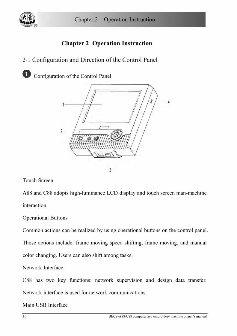
Configuration of the Control Panel
Touch Screen
A88 and C88 adopts high-luminance LCD display and touch screen man-machine
interaction.
Operational Buttons
Common actions can be realized by using operational buttons on the control panel.
Those actions include: frame moving speed shifting, frame moving, and manual
color changing. Users can also shift among tasks.
Network Interface
C88 has two key functions: network supervision and design data transfer.
Network interface is used for network communications.
Main USB Interface
Chapter 2 Operation Instruction
BECS-A88/C88 computerized embroidery machine owner’s manual 1 1
USB disk can be plugged in for data input/output.
Direction of the Control Panel
In order to extend the life of the control panel, please do not lay too much
pressure on the screen during operation. Try to avoid using hard or shape tools to
touch the panel.
Direction in Using the Floppy Disk
Make sure the plug-in direction is correct. Try to avoid using force with incorrect
plug-in direction, or it may destroy the floppy driver and disk.
Direction in Using the USB Disk
Please pay close attention to electrostatic phenomenon. Don’t forget to discharge
before plugging in/out the USB disk.
USB disk features plug-in direction. Users should avoid plugging out during
writing or loading data, because it may result in loss of data. We highly
recommend users to check the data integrality in case of data missing.
Note: During the process of USB format, sudden loss of electricity or plugging
out the disk may break down the USB.
Direction of Network Connection
Preset the network parameters before the connecting. Otherwise other machines in
the network maybe can’t communicate.
2-2 Instruction of Control Panel
Operation can become much easier by using shortcut keys and the touch screen on
the panel.

Chapter 2 Operation Instruction
12 BECS-A88/C88 computerized embroidery machine owner’s manual
Number Name Description
Task Shift If the user opens several screens, he can shift among the
screens by this key.
Low Needle Position Color-changing
Press this key, and the current needle position will move towards the low needle position till the first needle position.
High Needle Position Color-changing
Press this key, and the current needle position will move towards the high needle position till the highest needle position.
Manual Frame Moving
In operation the direction of frame-moving is the same as the direction key. The combination of directions is supported.
Speed Shift of Manual Frame-moving
Press this key to switch the frame-moving speed between
(high speed) and (low speed).
2-3 Instruction of the Main Screen
Note: in the following charts, the icons with are touch keys; those without
indicate the machine status.

Chapter 2 Operation Instruction
BECS-A88/C88 computerized embroidery machine owner’s manual 1 3
No. Display Name Description Reference
Memory Design Management
Click it to enter the memory design management screen, which includes “select design”, “disk input”, displaying designs, creating new designs and monogram operation.
Chapter 1 Page65
Disk Management
Click it to enter the disk management, which includes operations of floppy disk and USB disk.
Chapter 3 Page 34
Parameter Setup
Click it to enter the parameter setup screen which includes color changing order, normal parameters such as scaling down/up and repetition, general parameters such as sewing parameters, machine applying parameters and machine parameters.
Chapter 4 Page 48
Manual Color-changing
When the machine stops and the main
shaft reaches the set position ( ),
click it to enter the manual color-changing screen and then click the corresponding needle number to change color.
2-4 Page 30
Back to origin
When the machine stops, click it, the frame will automatically return to the start point of the current design.
2-4 Page 31
Chapter 2 Operation Instruction
14 BECS-A88/C88 computerized embroidery machine owner’s manual
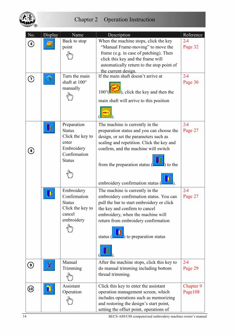
No. Display Name Description Reference
Back to stop point
When the machine stops, click the key “Manual Frame-moving” to move the frame (e.g. in case of patching). Then click this key and the frame will automatically return to the stop point of the current design.
2-4 Page 32
Turn the main shaft at 100° manually
If the main shaft doesn’t arrive at
100°( ), click the key and then the
main shaft will arrive to this position
( ).
2-4 Page 30
Preparation Status Click the key to enter Embroidery Confirmation Status
The machine is currently in the preparation status and you can choose the design, or set the parameters such as scaling and repetition. Click the key and confirm, and the machine will switch
from the preparation status ( ) to the
embroidery confirmation status ( ).
2-4 Page 27
Embroidery Confirmation Status Click the key to cancel embroidery
The machine is currently in the embroidery confirmation status. You can pull the bar to start embroidery or click the key and confirm to cancel embroidery, when the machine will return from embroidery confirmation
status ( ) to preparation status
( ).
2-4 Page 27
Manual Trimming
After the machine stops, click this key to do manual trimming including bottom thread trimming.
2-4 Page 29
Assistant Operation
Click this key to enter the assistant operation management screen, which includes operations such as memorizing and restoring the design’s start point, setting the offset point, operations of
Chapter 9 Page108

Chapter 2 Operation Instruction
BECS-A88/C88 computerized embroidery machine owner’s manual 1 5
No. Display Name Description Reference design periphery, positioning idling, and clearing accumulated stitch count and X/Y displacement.
Normal Embroidery
The machine is currently in normal embroidery status. When pulling the bar for normal embroidery, the main shaft rotates, the frame moves along the stitch trace and threads shape the design on the embroidery materials. When pulling the bar for returning, the machine returns in low-speed idling. When the machine stops, click this key to switch to the
low-speed idling status ( ).
2-4 Page 28
Low-speed Idling
The machine is currently in low-speed idling status. When pulling the bar for normal embroidery, the main shaft remains inactive and the frame advances along the stitch trace. When pulling the bar for returning, the main shaft remains inactive and the frame returns along the stitch trace. When the machine stops, click this key to switch to high-speed
idling status ( ).
2-4 Page 28
High-speed Idling
The machine is currently in high-speed idling status. When pulling the bar for normal embroidery, the main shaft and the frame remain inactive while the count of stitches decreases. When pulling the bar for stop, the frame directly moves to the actual position of the current stitch count. When the machine stops, click this key to switch to the normal embroidery
status ( ).
2-4 Page 28
Other Functions
Click this key to enter the “Other Function Operations” screen, which includes statistics information, zero point setting, continuing after power-off, setting the frame software range, access parameters management, touch screen adjusting, date/time and so on.
Chapter 10 Page 127

Chapter 2 Operation Instruction
16 BECS-A88/C88 computerized embroidery machine owner’s manual
No. Display Name Description Reference
Manual Color-changing Manual Start
In this status use manual
needle-changing ( or the
color-changing key on the panel)to select
the needle position before embroidery, and then pull the bar to start embroidery. When meeting the color-changing code during embroidery, the machine will halt automatically and the color-changing
icon ( ) appears. And the operator
need to do manual needle-changing
( or the color-changing key on
the panel) to select the needle position,
and then pull the bar to start embroidery(manual start).
2-4 Page 28
Automatic Color-changing Manual Start
2-4 Page 28
Automatic Color-changing Automatic Start
If the machine is set as automatic color-changing, the color-changing sequence should be set before embroidery
(click first, and then click
to do the setting). When pulling the bar to start, needle-changing will be done automatically following the set color-changing sequence and then embroidery will start. When meeting the color-changing code during embroidery, the machine will automatically halt and do the needle-changing following the settings. If it’s set as automatic start, the machine will start embroidery automatically. If it’s set as manual start, embroidery will start by pulling the bar.
2-4 Page 28
Design Information
Display the basic information of the selected design. The current stitches, X/Y displacement and other information will change with embroidering. To clear the

Chapter 2 Operation Instruction
BECS-A88/C88 computerized embroidery machine owner’s manual 1 7
No. Display Name Description Reference
X/Y displacement, click and then
in the following screen choose the option for clearing.
Decreasing the Main Shaft Speed
It’s used to decrease the main shaft speed (until the set lowest speed).
Increasing the
Main Shaft
Speed
It’s used to increase the main shaft speed (until the set highest speed).
High-speed Manual Frame Shifting Status
When the machine stops, press the manual frame-shifting keys to move the frame, and the frame will move in the high speed. Switch between
and can be achieved by
pressing the switching key on the panel.
Low-speed Manual Frame Shifting Status
It’s opposite to the high-speed manual frame shifting status and used for speed-adjusting.
The main shaft stops at the right position (100°).
When the machine stops while the main shaft stops at the right position, you can do operations such as color-changing and frame-moving.
The main shaft hasn’t stopped at the right position (100°).
When the machine stops and the main shaft hasn’t reached the right position, you need to turn the shaft to the 100°position manually by clicking
.
The main shaft runs well.
The main shaft runs well in embroidering.
Assistant Operation Status Click to enter the assistant
operation management screen and select any one of embroidering along the design range, one line, one cross and the design

Chapter 2 Operation Instruction
18 BECS-A88/C88 computerized embroidery machine owner’s manual
No. Display Name Description Reference
outline, and then the icon will
appear after coming back to the main screen.
Thread Break Prompt
When the thread breaks and machine stops, this icon appears.
Color-changing Prompt
The machine stops and color-changing is performed.
Cyclic Embroidery Prompt
The machine is currently set with cyclic embroidery.
Click to enter the parameter
management screen, in which the cyclic parameters can be set.
Offset Point Prompt
The machine is currently set with offset point. When entering the embroidery
confirmation status (before
starting embroidery), click to enter
the assistant operation management screen, in which you can set offset point.
Help for the Main Screen
It’s the function definitions of the keys on the main screen.
Network Connection Failure This icon is black. Click to set
network concerned parameters in “Machine Apply” screen
Network Connection Success
This icon is blue.
Current Needle Position
The number represents the current actual needle position.
Current Color-changing Times
The initial value is 1, which is added one with every time of successful color-changing.
Color-changing Order
The order of the numbers represents the needle-changing sequence. And the

Chapter 2 Operation Instruction
BECS-A88/C88 computerized embroidery machine owner’s manual 1 9
No. Display Name Description Reference three-dimensional icon represents the
current icon.
Design viewing Area
This area displays the embroidery designs.
2-4 Notes on Menu State
If one menu is labeled , it indicates that this menu can not be accessed and
modified. While if one menu is labeled , it indicates that this menu can not be
accessed and modified. If there is a “Lock” on the right side of the window, then
this parameter can be modified only if the relieving the password first.
2-5 Flow Chart of Embroidery
The machine embroiders based on the designs in its memory. The following is the
basic Flow Chart of Embroidery.

Chapter 2 Operation Instruction
20 BECS-A88/C88 computerized embroidery machine owner’s manual
Input of Designs
The user can input designs through network, floppy disk or USB disk. Only with
(blue) it’s possible to transmit designs by network. For disk operation, click
in the main screen to enter into the “disk management” screen. You can
also input designs by choosing “Disk Input” in the design management screen.
Choosing a Design
If the design management screen is not opened, click in the main screen to
Choosing a Design
Assistant Operations
Embroidery Confirmation
Pull the Bar to Embroidery
Cancel Embroidery
Inputting Designs
Inputting Designs Inputting Designs Inputting Designs Inputting Designs
Manual Operation

Chapter 2 Operation Instruction
BECS-A88/C88 computerized embroidery machine owner’s manual 2 1
enter it. If the screen is opened but the current window stays at another function
screen, press the blue task switch key on the panel to enter the design
management screen. Only in the status , it’s allowed to choose design for
embroidery.
Click “Select Design” in the design management screen.
If the design’s start point has been saved, the prompt “Move frame to design’s
start” will appear when entering the main screen. Click and the frame will
automatically return to the start point.
Chapter 2 Operation Instruction
22 BECS-A88/C88 computerized embroidery machine owner’s manual
Assistant Operation
After choosing the design, the user will enter the main screen, and he can do the
needed assistant operations before embroidery.
Set repetition, rotation and scaling up/down——click to enter the
parameters management screen
Set the color-changing order—— click and then needle (color)
changing to enter the color-changing screen
Set patching embroidery——click to enter the design management
screen. Then click “More Functions” to set patching according to prompts
Show the range of embroidery design, move frame along the design range,
embroider along the design range, embroider one cross, embroider one line,
embroider the design outline——click to enter the assistant operation
screen
Move frame to let design be central——click to enter the assistant
operation screen. Note: this function is to place the design at the centre of the
design range set by software (soft range of design). To set the soft range of design,
click to enter the “Other Function Operations”.
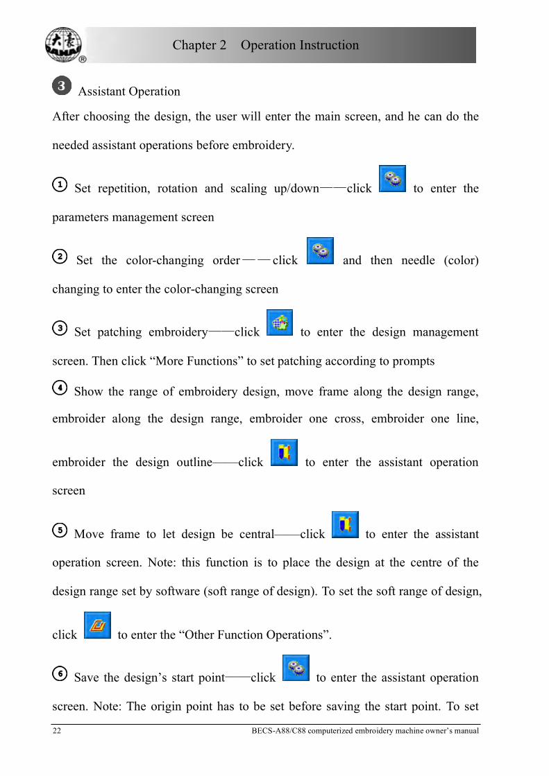
Save the design’s start point——click to enter the assistant operation
screen. Note: The origin point has to be set before saving the start point. To set

Chapter 2 Operation Instruction
BECS-A88/C88 computerized embroidery machine owner’s manual 2 3
the origin point, click to enter the “Other Function Operations”.
Set cyclic embroidery——click to enter the parameter management
screen. Then click “Sewing Para1” and set according to prompts.
Embroidery Confirmation
• The user can click after finishing assistant operations. Choose
in the followed prompt and (embroidery preparation) will
change into (embroidery confirmation), which means that the machine
has entered the embroidery confirmation status.
If is chosen, the machine will remain in the preparation status. Pull the bar
and the machine will not run and a prompt will appear to ask the user to confirm
embroidery.
Setting Off-Set Point
After embroidery confirmation, if needed, click to set off-set point
Chapter 2 Operation Instruction
24 BECS-A88/C88 computerized embroidery machine owner’s manual
according to the prompts. Note: It’s of no effect to set off-set point after starting
embroidery.
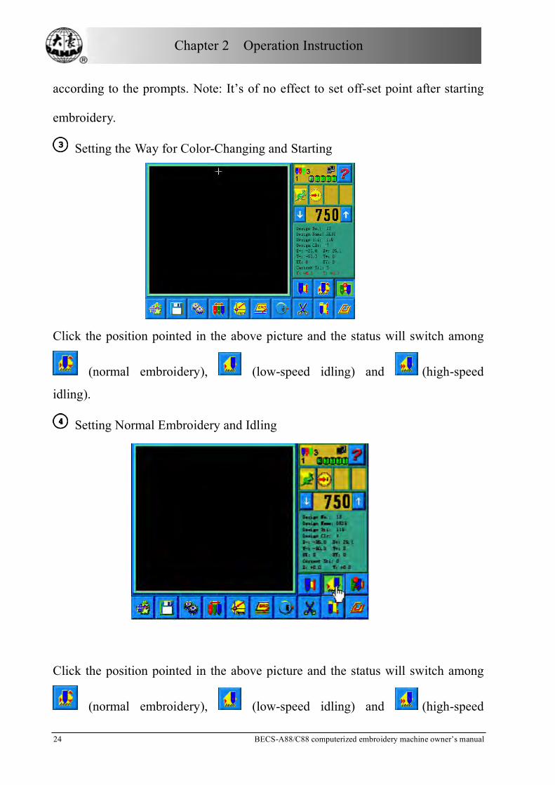
Setting the Way for Color-Changing and Starting
Click the position pointed in the above picture and the status will switch among
(normal embroidery), (low-speed idling) and (high-speed
idling).
Setting Normal Embroidery and Idling
Click the position pointed in the above picture and the status will switch among
(normal embroidery), (low-speed idling) and (high-speed

Chapter 2 Operation Instruction
BECS-A88/C88 computerized embroidery machine owner’s manual 2 5
idling).
Pull the Bar to Embroider
Operation bar (embroidery bar under the table)
Stop Status:
Pull the bar right to begin embroidery (including low and high speed idling)
Pull the bar left to return (including low and high speed idling)
Running status:
Pull the bar right to the end to embroider slowly and release to normal speed.
Pull the bar left to stop embroidery (including low and high speed idling).
Manual Operation
Manual Trimming
When the machine stops, click in the main screen. In the followed prompt
click to trim, or click to trim the bottom
thread. Click to exit trimming operation.
Manual Frame-Moving
When the machine stops, press the keys (“ ”、“ ”、“ ”、“ ”) to move

Chapter 2 Operation Instruction
26 BECS-A88/C88 computerized embroidery machine owner’s manual
the frame in the corresponding direction. Press the next two keys at the same time
to move the frame in the direction of the angle bisector. “ ”is the speed key for
manual frame-moving. Press “ ”to switch between (high speed) and
(low speed).
Clearing the Frame Coordinates
When the machine stops, click and then the function option
to clear the XY displacements displayed in
the main screen. The function can be used with manual frame-moving.
Manual Color-Changing
When the machine stops, click in the main screen to enter the manual
color-changing screen. Then click the needle number for color-changing, and the
machine head will automatically move to the corresponding needle position. It’s
also possible to do color-changing by pressing the color-changing shortcut keys
marked with “+,-”. Please note: if the user wants to automatically save the
order of the manual color-changing (yes for “Store Manual Color” in embroidery
parameters), it has to be operated in the manual color-changing screen of the
touch screen.
Turn the Main Shaft to 100°Manually
Usually the main shaft is needed to stop at 100°when needle/color-changing,
frame-moving and beginning embroidery. The user can manually turn the main

Chapter 2 Operation Instruction
BECS-A88/C88 computerized embroidery machine owner’s manual 2 7
shaft at 100° when it hasn’t reached there. Click in the main screen and
then choose in the followed prompt to carry out the function.
After the operation, the icon (main shaft not in the right position) will be
replaced by (main shaft in the right position).
Back to the origin
In the main screen click and choose in the followed prompt. Then
the frame will return to the start point.
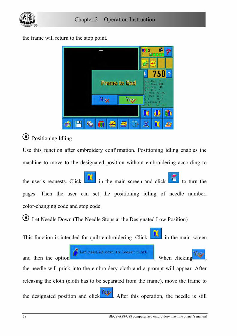
Back to Stop Point
Click in the main screen and choose in the followed prompt. Then
Chapter 2 Operation Instruction
28 BECS-A88/C88 computerized embroidery machine owner’s manual
the frame will return to the stop point.
Positioning Idling
Use this function after embroidery confirmation. Positioning idling enables the
machine to move to the designated position without embroidering according to
the user’s requests. Click in the main screen and click to turn the
pages. Then the user can set the positioning idling of needle number,
color-changing code and stop code.
Let Needle Down (The Needle Stops at the Designated Low Position)
This function is intended for quilt embroidering. Click in the main screen
and then the option . When clicking ,
the needle will prick into the embroidery cloth and a prompt will appear. After
releasing the cloth (cloth has to be separated from the frame), move the frame to
the designated position and click . After this operation, the needle is still

Chapter 2 Operation Instruction
BECS-A88/C88 computerized embroidery machine owner’s manual 2 9
down. When the cloth is place on the frame again, click to turn the main
shaft to 100º manually.
Manual Operations of Automatic Frame Changer (AFC), Sequin and Special
Embroidery
Some machines are equipped with devices for AFC, sequin and special
embroidery. For such machines, click and then
to enter the concerned menu. Click the
corresponding keys according to the prompts.
Embroidery Cancel
When the machine stops, click . Choose in the followed prompt and
(embroidery confirmation) will change into (embroidery cancel).

Chapter 2 Operation Instruction
30 BECS-A88/C88 computerized embroidery machine owner’s manual
2-6 Normal Embroidery, Returning and Patching
In embroidery confirmation status (the icon appears), push the patching
switch of machine head (that will perform normal embroidery) to the normal
embroidering mode, and push the patching switch of machine head that will not
embroider to the patching mode, and then pull the operation bar to right and
release it to let the machine start normal embroidery. (When you pull the bar right
and don't release it, the machine will embroider in lower speed.) During
embroidering, pull the bar left, the machine will stop.
After the machine stops, pull the operation bar to left and the frame will return to
its last position along original path. Pull the bar one time, the frame return one
needle step. Pull the bar continuously and the frame will return one needle step
after another continuously. After the frame return 10 needle steps continuously,
the frame can return continuously even when you release the bar. (This may be
different for different machine types). When the frame return continuously,
release the bar and pull it left again, the frame will stop returning.
The aim of returning is usually to perform patching embroidery. After the
returning stops, push the patching switch of machine head that will perform
patching embroidery to go to the patching mode, and then pull the operation bar
to right and the machine head will start patching embroidery while other heads
don't. When the frame goes to the point where the frame begins to return, other
heads whose patching switches are in normal embroidering mode will start to
embroider.

Chapter 2 Operation Instruction
BECS-A88/C88 computerized embroidery machine owner’s manual 3 1
2-7 Operation Bar and Turn Shaft Button
Operation Bar (Embroidery Bar under the Table)
Stop status: pull the bar right to begin embroidery (including idle running in high
or low speed) and pull the bar left to return (including idle running in high or low
speed)
Running status: pull the bar right to the end to embroider slowly and release to
normal speed and pull the bar left to stop embroidery.
Turn Shaft Button (over the operation bar case, on the right under the table)
To press the button to make the main shaft rotate one cycle and stop at 100±2.5
°.
2-8 Patching Switch
Thread Break Detecting Device of 3-Place
There is a switch on every head of machine. When the switch is up, this head is in
normal embroidering mode and when it is in the middle, this head is in patching
mode and when it is down this head is in stop mode.
Thread Break Detecting Device of 2-Place
On every head of the machine, there is a patching switch, and it can be move with
hand to the up, middle or down position, but it is stop only at the middle or down
position. When the switch is pushed to up position, it cannot stay at up position,
and the lamp is red, which hints that this head is in patching mode. In addition,
while thread breaking during embroidering, the lamp is automatically changed
into red and this head is in patching mode. When the switch is at middle position,

Chapter 2 Operation Instruction
32 BECS-A88/C88 computerized embroidery machine owner’s manual
this head is in patching mode if the lamp is red, or this head is in normal
embroidering mode if the lamp is green. When the switch is pushed to down
position, the lamp is off, which hints that this head is in stop mode. When the
switch is pushed to middle position from down position, the lamp will be green
and the head is in normal embroidering mode.
2-9 System's Working Statuses
The machine has three working statuses:
Preparation status preset parameters; choose embroidery designs
and other preparation work
Embroidery confirmation status confirm the parameter settings to
enter the quasi-running status
Embroidery running status embroidering
How to switch among the above work statuses?
In preparation status ( is displayed), after selecting pre-embroidery design
and setting the parameters, first press " " key, and then press " " key,
now the machine is in embroidery confirmation status ( is displayed).
Finally, pull the embroidery bar to right to embroider, which means the machine
is in embroidery running status ( is displayed).

Chapter 2 Operation Instruction
BECS-A88/C88 computerized embroidery machine owner’s manual 3 3
In embroidery running status ( is displayed), pull the bar left to stop, now
the machine is in embroidery confirmation status (Again, pull the bar right, the
machine goes into embroidery running status).
In embroidery confirmation status ( is displayed), first press " " key.
And then press " " key to release embroidery confirmation status. Now the
machine enters preparation status ( is displayed).

Chapter 3 Disk Management
34 BECS-A88/C88 computerized embroidery machine owner’s manual
Chapter 3 Disk Management
In disk management, users can input the designs in the disk to machine, and
vise versa; meanwhile, users can enjoy some common disk managing actions, like
erasing file, formatting disk, etc. floppy disk and USB disk are both supported.
Users can save design data based on different types. The system recognizes
formats like DOS, FDR and ZSK. However, FDR and ZSK files are read only.
Design formats like DSB, DST and DSZ can be read. For data output, design will
be saved as DSB format.
3-1 Disk Choosing
Since the system support more than one storage device, please choose the
objective disk.
Click in the main screen
The prompt “Please Select Device” will appear. And choose the disk used
for the next operation.

Chapter 3 Disk Management
BECS-A88/C88 computerized embroidery machine owner’s manual 3 5
In this window all the storage devices will be displayed. Their information
includes the icons, words and numbers. The icon is the device type. Means
USB disk and means floppy disk. The words are the volume name of the
disk and the number in the brackets is for the disk’s digital symbol.
Enter the Disk Management Screen.
Chapter 3 Disk Management
36 BECS-A88/C88 computerized embroidery machine owner’s manual
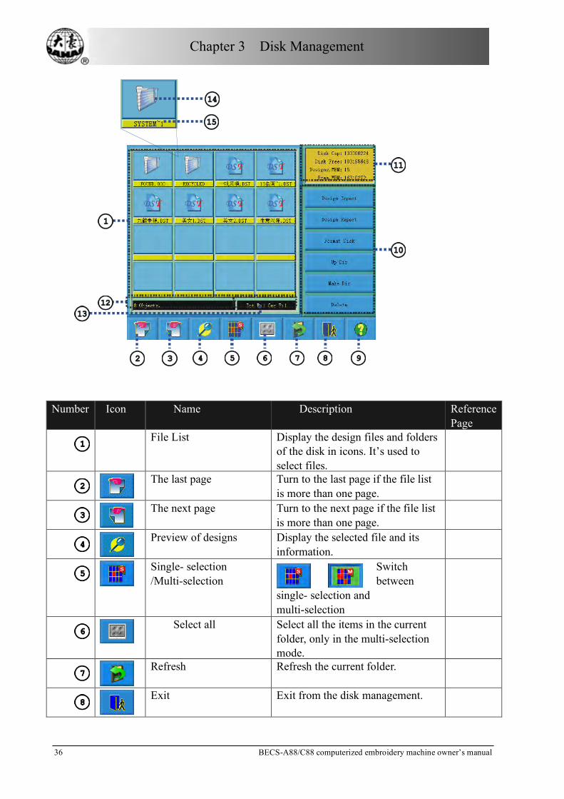
Number Icon Name Description Reference
Page
File List Display the design files and folders
of the disk in icons. It’s used to select files.
The last page Turn to the last page if the file list
is more than one page.
The next page Turn to the next page if the file list
is more than one page.
Preview of designs Display the selected file and its
information.
Single- selection /Multi-selection
Switch between
single- selection and multi-selection
Select all Select all the items in the current
folder, only in the multi-selection mode.
Refresh Refresh the current folder.
Exit Exit from the disk management.

Chapter 3 Disk Management
BECS-A88/C88 computerized embroidery machine owner’s manual 3 7
Number Icon Name Description Reference Page
Help Display the help menu.
Option key list List the main option keys for disk
management.
Disk and memory
information Display the storage and left space of disk and memory.
Operation Information Display the current operation
information: the file number in the current folder, information of the selected file and design.
Page information The current page number and total
page number
Icons of the objects
for folder
for files of DSB form
for files of DST form
Names of the objects Names of the files or folders
3-2 Select One or Several Designs
Before preview, input and deletion of files, the objective design has to be selected
first. The user can select one object for one time, and can also select several
objects for one time to improve efficiency.
Select One Object
The objects are by default in the unselected status. When one of them is selected,
its icon and words will show a different color and the information area will show

Chapter 3 Disk Management
38 BECS-A88/C88 computerized embroidery machine owner’s manual
its contents like stitch number and data.
Click a Selected Object to Cancel the Selection
Click a selected object and it will become unselected again.
Click the Switch Key of Single/Multi-Selection
When selecting the objects, the system is in single or multi-selection mode. In the
single selection mode, one object is selected for one time and selecting another
object will automatically cancel the last selection. Click the switch key to switch
between the two modes. In the multi-selection mode the user can select several
objects. In the single selection mode the switch key shows when in the
multi-selection mode it shows .
Select More Than One Object
In the multi-selection mode click the several objects in order to select them.

Chapter 3 Disk Management
BECS-A88/C88 computerized embroidery machine owner’s manual 3 9
Click to select all the objects in the current folder
The key is effective only in the multi-selection mode.
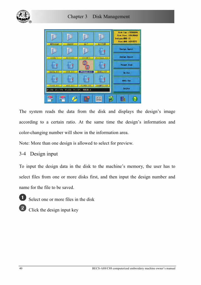
3-3 Design Preview
Click and select the design in the disk management screen
Design files and folders are shown by icon in the list. One page of the list contains
16 items. Click the key to turn pages to look for designs in another page. The
selected object has a green frame and a different background color.
Click Design Preview Key
Chapter 3 Disk Management
40 BECS-A88/C88 computerized embroidery machine owner’s manual
The system reads the data from the disk and displays the design’s image
according to a certain ratio. At the same time the design’s information and
color-changing number will show in the information area.
Note: More than one design is allowed to select for preview.
3-4 Design input
To input the design data in the disk to the machine’s memory, the user has to
select files from one or more disks first, and then input the design number and
name for the file to be saved.
Select one or more files in the disk
Click the design input key

Chapter 3 Disk Management
BECS-A88/C88 computerized embroidery machine owner’s manual 4 1
The system asks the customer to input design number and name for system
saving.
The user inputs the design number and name.
The system provides the minimum available design number as the default value.
The customer can use the small panel on the right to change the value. When
several designs are input for one time, the user can only input the number of the
Chapter 3 Disk Management
42 BECS-A88/C88 computerized embroidery machine owner’s manual
first design.
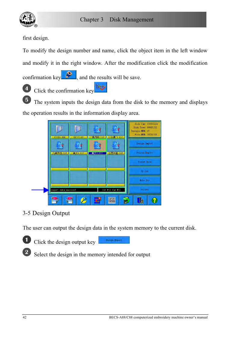
To modify the design number and name, click the object item in the left window
and modify it in the right window. After the modification click the modification
confirmation key , and the results will be save.
Click the confirmation key
The system inputs the design data from the disk to the memory and displays
the operation results in the information display area.
3-5 Design Output
The user can output the design data in the system memory to the current disk.
Click the design output key
Select the design in the memory intended for output

Chapter 3 Disk Management
BECS-A88/C88 computerized embroidery machine owner’s manual 4 3
The system displays the list of designs in system memory. The user selects the
designs intended for output, and then click .
Input of the design name for disk saving
The system uses the design name in system memory as the default design name in
disk. Click after input of the design name in disk.
To change the design name in disk, first click the item in the left window, and
then change it in the right window. After the changing, click to save the
result.
Chapter 3 Disk Management
44 BECS-A88/C88 computerized embroidery machine owner’s manual
The system returns to the disk management screen.
3-6 Folder Operation
Enter the folder
Double click the icon of the objective folder to enter it. The system reads the item
list of the folder and refreshes the screen.
Return to the higher level of folder
Click to return to the highest level of folder and the screen will be
refreshed.
3-7 Formatting a Disk
Select the disk device for formatting (read 4.1 for reference)
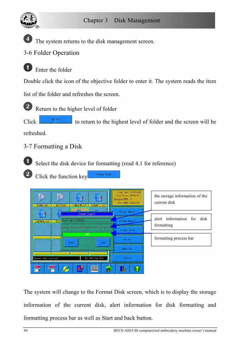
Click the function key
The system will change to the Format Disk screen, which is to display the storage
information of the current disk, alert information for disk formatting and
formatting process bar as well as Start and back button.
the storage information of the current disk
alert information for disk formatting
formatting process bar

Chapter 3 Disk Management
BECS-A88/C88 computerized embroidery machine owner’s manual 4 5
Click the Key
The system will begin to format the disk and show the speed with a process bar.
After formatting the system will display the prompt to show formatting success.
Click the returning key to return to the disk management screen.
Note: the system will format the disk in DOS format.
3-8 Deleting Objects in Disk (Including Design Files and Folders)
Select one or more objects (See 4.2)
Click the deleting key
The system asks the user to confirm the deleting operation
Chapter 3 Disk Management
46 BECS-A88/C88 computerized embroidery machine owner’s manual
Note:
If the user chooses to select a folder, the system will delete all the files and
sub-folders in this folder. If a file has the property of “only read” or “disk write
protection”, the file will not be able to delete.
3-9 Creating a New Folder in the Current Folder
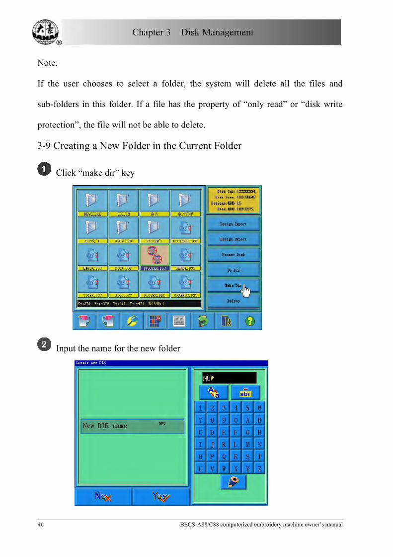
Click “make dir” key
Input the name for the new folder

Chapter 3 Disk Management
BECS-A88/C88 computerized embroidery machine owner’s manual 4 7
Click to confirm
The system will create the corresponding folder in the disk and refresh the current
list of objects.

Chapter 4 Common Parameters and Color-changing Order
48 BECS-A88/C88 computerized embroidery machine owner’s manual
Chapter 4 Common Parameters and Color-changing Order
In this system each design has its own settings of the normal parameters (like
scaling up/down and repetition) and color-changing order. When a new design is
selected, the corresponding settings of normal parameters and color-changing
order become effective.
This chapter is to introduce the settings of normal parameters and color-changing
order, which is entered by clicking in the main screen.
This system supports multi-missions at the same time. So it’s possible to set or
change the normal parameters and color-changing order of non-current designs.
To do this click “More Functions” in the memory design management screen.
(See Chapter 6)
4-1 Normal Parameters
Normal parameters include: “X&Y Scales”, “Rotate”, “Direction”, “Prior Mode”,
“Rep. Mode”, “Rep. Prior”, “X&Y Reps” and “X&Y Interval”. The user can
control the final embroidery results by adjusting these parameters. That’s why
these parameters are often to be adjusted when a design is selected.
Enter the normal parameter setting screen by clicking in the main screen.

Chapter 4 Common Parameters and Color-changing Order
BECS-A88/C88 computerized embroidery machine owner’s manual 4 9
The way to set each parameter is similar. This chapter will explain how to set the
“X&Y Scales” as an example and give the definitions of other parameters (Read
4.1.1 as reference).
4.1.1 Setting “X&Y Scales”
This parameter controls the scaling percentages on horizontal (X) and vertical (Y)
directions, so as to scale up/down the design.
Click the option “X&Y Scales” Design start bit
X&Y Scales:
X : 2 0 0 %
Y : 5 0 %
Design start bit

Chapter 4 Common Parameters and Color-changing Order
50 BECS-A88/C88 computerized embroidery machine owner’s manual
Click “X&Y Scales” in the normal parameter screen, and the right of the screen
will show the parameter-setting window.
Set the parameter “X&Y Scales”
Click the number panel in the parameter-setting window to change the scaling
ratio on X/Y direction. The user can click to remove the last input digit and
click to remove all the input digits. Click and to switch between
the parameter’s X and Y scaling values. To change the corresponding parameter
value, first click the key before that. This method is also often used in
many other similar situations.
Click the confirmation key to save the change

Chapter 4 Common Parameters and Color-changing Order
BECS-A88/C88 computerized embroidery machine owner’s manual 5 1
After setting the parameter, the user has to click to confirm the change
and the system will save the change.
4.1.2 Setting of “Rotate”
The user can make the design to rotate to a certain angle with this parameter.
4.1.3 Setting of “Direction”
Design direction
Embroidery shape
PF
PF
FF
FP
PP
4.1.4 “Prior Mode”
There are two modes: rotating prior to scaling and scaling prior to rotating. When
the user has set the parameters “X&Y Scales” and “Rotate”, the design will rotate
first and then scale up/down with the setting rotating prior to scaling. Otherwise it
will scale up/down first and then rotate.
4.1.5 “Rep. Mode”
This system temporarily cannot support partial repetition.
Design start bit
Rotate 30 degrees

Chapter 4 Common Parameters and Color-changing Order
52 BECS-A88/C88 computerized embroidery machine owner’s manual
4.1.6 “Rep. Prior”
There are two modes: X prior to Y and Y prior to X.
X interval
Y interval
X prior Y prior
4.1.7 “X&Y Reps”
X Reps of this parameter sets the number of rows in repetition, and Y Reps of it
sets the number of columns in repetition. The above diagram shows that X Reps is
3 and Y Reps is 2. The largest set value is 99*99.
4.1.8 “X&Y Interval”
The above diagram also explains the meaning of this parameter.

Chapter 4 Common Parameters and Color-changing Order
BECS-A88/C88 computerized embroidery machine owner’s manual 5 3
4-2 Setting of Color-changing order
4.2.1 Color-changing Screen
number Icon Name Description Reference Page
Design display
Area Display the design according to real-time setting of color-changing order. Preview the result of color-changing
List of color block
sequence numbers Display the sequence numbers of the color blocks in the design.
List of needle
sequence numbers Display the needle sequence numbers corresponding to the color blocks.
List of needle
colors Display the thread colors for the color blocks in the design.
Move downward Move downward the color-changing list to select the color block.
Move upward Move upward the color-changing list to select the color block.
Insert a needle number
Click this key and a needle number to insert it in the current list of needle sequence

Chapter 4 Common Parameters and Color-changing Order
54 BECS-A88/C88 computerized embroidery machine owner’s manual
number Icon Name Description Reference Page
numbers.
Delete a needle number
Delete the needle number in the current operation position of the needle sequence numbers. List
The current
operation position The user can set, insert or delete a needle number in the position.
Set the cyclic needle number
Cyclic setting according to the needle sequence number list before the current color block
Setting of needle color
Select and set needle colors in the default colors.
Interchange needles
Open the needle interchanging screen and set it.
Help Display the help menu.
Needle number
selection area Select needle number here.
Cancel Cancel the color-changing
setting of this time and return.
Confirm Save the color-changing
setting and return.
The design display area displays the designs which are under color-changing
setting. Design display will change with the setting at the same time.
Color-changing order display area shows color blocks, needle numbers and needle
colors.
Design display can be in parallel with the setting, inserting and deleting needle
number. It means that the user don’t need to wait for the ending of design display
to do the setting and changing of color-changing order
4.2.2 Setting of the color-changing order
Click in the main screen to enter the parameter setting screen.

Chapter 4 Common Parameters and Color-changing Order
BECS-A88/C88 computerized embroidery machine owner’s manual 5 5
Click in the parameter setting screen to enter the color-changing
screen.
Input the needle numbers in order in the needle number selection area. The
design display in the design display area and the color list in the color-changing
display area will refresh with the input of each needle number.
Click to see if the input color-changing order is correct.
To change a needle number in the color-changing order, the user can click
to move the list to place the intended item to the current operation
position, and then click the new needle number.
To insert a needle number in the color-changing order, click to
move the order list to place the intended item to the current operation position,
and then click to insert a needle number after the current item.
To delete a needle number, click .
If the user has affirm that the first N items are set correctly and hope to
repeat the settings of the first N items from the N+1 item, he can click
to move the order list to place the item N+1 to the current operation position and
then click .
Click to confirm the input setting. Click to cancel the setting and
return.

Chapter 4 Common Parameters and Color-changing Order
56 BECS-A88/C88 computerized embroidery machine owner’s manual
4.2.3 Setting Needle Color
To make the color display in the screen get close to the design color in real
embroidery, this system can set all the needle colors used by the current design.
This setting will be saved with color-changing for the design.
Click in the main screen to enter the parameter setting screen.
Click in the parameter setting screen to enter the color-changing
setting screen.
Click to enter the needle color setting screen.
In the needle color setting screen there are totally 40 default colors for selection.
To set the needle color, select the needle first and then select the color from
the 40 default color blocks. The corresponding color will be refreshed on the
needle button.
Click to save the needle color setting and return to the color-changing

Chapter 4 Common Parameters and Color-changing Order
BECS-A88/C88 computerized embroidery machine owner’s manual 5 7
order setting screen. Click to cancel the setting and return.
4.2.4 Interchanging of Needle Colors
Click in the main screen to enter the parameter setting screen.
Click in the parameter setting screen to enter the color-changing
screen.
Click to enter the needle color interchanging screen.
To interchange the needle colors, click to move the order list to
select the needle and then select another needle from the needle buttons.
Click to save the setting and return. Click to cancel the setting
and return.

Chapter 5 Setting General Parameters
58 BECS-A88/C88 computerized embroidery machine owner’s manual
Chapter 5 Setting General Parameters
In the parameter setting screen, normal parameters and color-changing are for the
current embroidering design, while other parameters are called general meters.
The general parameters include three groups: embroidery parameters, machine
application parameters and machine parameters. In embroidering, the embroidery
parameters may change with design and embroidery method. They cannot be set
with passwords. The machine application parameters are for administrators of the
embroidery factories and can be set with administrator password. Machine
parameters are for the machine producer to use and usually don’t need to be
changed in working, which can be set with producer password. Click to enter
the “Access parameters management” screen, and then you can set administrator
and producer passwords as well as set parameters to default. (See Chapter 9)
Refer to the appendix one for every parameter’s definition.
Click in the main screen.
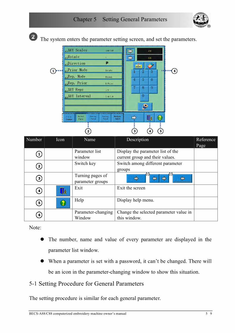
Chapter 5 Setting General Parameters
BECS-A88/C88 computerized embroidery machine owner’s manual 5 9
The system enters the parameter setting screen, and set the parameters.
Number Icon Name Description Reference
Page
Parameter list
window Display the parameter list of the current group and their values.
Switch key Switch among different parameter
groups
Turning pages of
parameter groups
Exit Exit the screen
Help Display help menu.
Parameter-changing
Window Change the selected parameter value in this window.
Note:
The number, name and value of every parameter are displayed in the
parameter list window.
When a parameter is set with a password, it can’t be changed. There will
be an icon in the parameter-changing window to show this situation.
5-1 Setting Procedure for General Parameters
The setting procedure is similar for each general parameter.

Chapter 5 Setting General Parameters
60 BECS-A88/C88 computerized embroidery machine owner’s manual
Select the parameter group.
The user can use the keys on the bottom of the screen to look for the parameter.
And ensure no password or it has been input. (See Chapter 9)
If you want to change the value of “Needles”, (which is D01 in machine
parameters 1) click to find machine parameters 1 and select it. Then all
of its parameters will be shown in the parameter list window.
Select the parameter.
Select the parameter in the list and in the right parameter-changing window there
will appear keys to change the value. If it’s already set with a password, the value
will not be able to change and an icon will show.

Chapter 5 Setting General Parameters
BECS-A88/C88 computerized embroidery machine owner’s manual 6 1
Change the current parameter in the parameter-changing window.
Click the keys to change the values.
Click the confirmation key to finish the setting.

Chapter 5 Setting General Parameters
62 BECS-A88/C88 computerized embroidery machine owner’s manual
Click to confirm and the system will save the result.
5-2 Introduction of Some Functions of General Parameters
There are brief introductions of the parameters in the appendix one. Here are
some functions used in embroidery.
5.2.1 Cyclic Embroidery
This function is to increase the embroidery productivity.
When the parameter“To Do Cyclic Emb.”is set as “Yes”, the cyclic embroidery
function is enabled and the icon will appear in the main screen. When this
function is enabled, after completing the designated design the machine will
automatically embroider it again without pulling the bar.
Usually cyclic embroidery accompanies repetition embroidery and special
punched designs and the parameter “Auto Origin” should be also set as “Yes”.
Thus when the machine is embroidering the back embroidery cloth-piece, the
front one can be replaced. After embroidering the designated design, the frame
will automatically return to the start point and the machine will automatically

Chapter 5 Setting General Parameters
BECS-A88/C88 computerized embroidery machine owner’s manual 6 3
embroider the front cloth-piece again and at this time it’ possible to replace the
back one.
5.2.2 Store Manual Color-changing
In embroidery confirmation status, the user can choose whether to store the
manual color-changing’s needle position into the color-changing order unit. Its
purposes are as follows: 1) If mistakes are found for the automatic color-changing
order in embroidering, the color-changing order can be modified with manual
color-change. 2) When a new design is embroidered with manual color-change
once, the color-change order is set for the design.
To use this function, the user should set the parameter “Store Manual Color” as
“Yes”. Note: the parameter value will automatically change into “No” at the end
of one design embroidering.
5.2.3 Brake Adjustment (A Must for New Machine)
This function is to adjust the control parameters for braking, so as to fit machines
of different mechanical characteristics, which also change with the machine
running. Thus this function can help the machinery parts to work better with the
computer. The function depends on the two parameters “Set Brake Para” and
“Main Motor Para.”.
“Set Brake Para” is to adjust the stop position of the main shaft. When the main
shaft often stops at less than 100 degree, the user can increase the parameter value.
When the main shaft often stops at more than 100 degree, the user can decrease
the parameter value. Thus the user can adjust the value to let the main shaft stop

Chapter 5 Setting General Parameters
64 BECS-A88/C88 computerized embroidery machine owner’s manual
close to 100 degree. The value can be set between 0 and 30.
“Main Motor Para.” is to adjust cooperation between main shaft motor and
machinery parts. The parameter value can be set between 0 and 30, and set as 0 in
most situations. When during braking the main shaft vibrate without moving or
rotate in the reverse direction, the user can increase the parameter value.
After adjusting these parameters, the user can click the task swift key on the panel
to return to the main screen. Click and , to check the effects of the
parameter adjustment. If the user is not satisfied with the effects, he can press the
swift key on the panel to return to the parameter setting screen, where he can
adjust the parameter setting again. Close the parameter setting screen in the end.
5.2.4 Forbidding Design Output
The function is to forbid copying the designs in memory (into the disk). If the
machine administrator set “No Output Design” as “Yes”, other persons are unable
to output the designs to the disk. If the user needs to output, he has to cancel “No
Output Design” first.
To use this function, the administrator password has to be set and it’s possible to
change this parameter after inputting the correct administrator password (refer to
10.7 machine management access).

Chapter 6 Memory Design Management
BECS-A88/C88 computerized embroidery machine owner’s manual 6 5
Chapter 6 Memory Design Management
Memory design management includes selecting embroidery designs, setting
designs and operations to create designs.
6-1 Memory Design Management Screen and Other Memory Design
Operation Screens
Click in the screen to enter the memory design management screen.
The memory design management screen includes: design image display area,
navigation and pagination area, information area, menu and memory design
management operation area. The design image display area can show 25 designs
at most, beyond that more pages are needed. Navigation and pagination area can
help switch to the designated page. The memory design management operation
area is to preview designs and set their order.

Chapter 6 Memory Design Management
66 BECS-A88/C88 computerized embroidery machine owner’s manual
Number Icon Name Description Reference Page
Design image
display area Show the design files in memory by icons. It’s mainly for selection purpose.
Navigation and
pagination area It’s for quick switching to the designated page of memory design list.
Information
area Display the detailed information of the selected design and memory information.
Select design In the embroidery
preparation status use the selected design as embroidery design.
Disk input Open the disk
management screen to input the designs.
More functions Click it to do operations such as design copying, deleting, combination and editing.
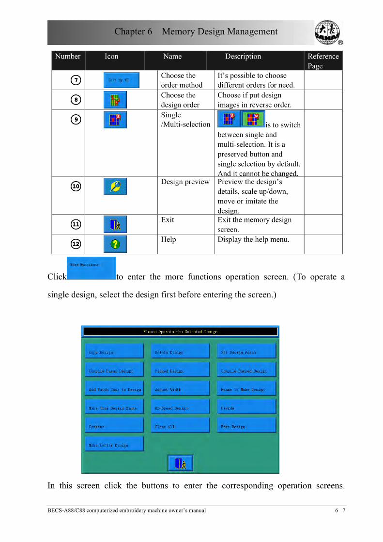
Chapter 6 Memory Design Management
BECS-A88/C88 computerized embroidery machine owner’s manual 6 7
Number Icon Name Description Reference Page
Choose the order method
It’s possible to choose different orders for need.
Choose the design order
Choose if put design images in reverse order.
Single /Multi-selection is to switch
between single and multi-selection. It is a preserved button and single selection by default. And it cannot be changed.
Design preview Preview the design’s
details, scale up/down, move or imitate the design.
Exit Exit the memory design
screen.
Help Display the help menu.
Click to enter the more functions operation screen. (To operate a
single design, select the design first before entering the screen.)
In this screen click the buttons to enter the corresponding operation screens.

Chapter 6 Memory Design Management
68 BECS-A88/C88 computerized embroidery machine owner’s manual
Please read the following paragraphs for detailed explanation. Click to
return to the memory design management screen.
6-2 Selecting a Design for Embroidery
Select a new design (Ensure that the system is in preparation status )
Click in the main screen to enter the memory design management
screen.
Select the design in the memory design image area of the memory design
management screen.
Click to set the selected design as the embroidery design. If
the operation is completed, the system will close the memory design screen to
return to the main screen.
6-3 Memory Design Preview
The selected design can be previewed in the memory design preview screen
according to the designated way.
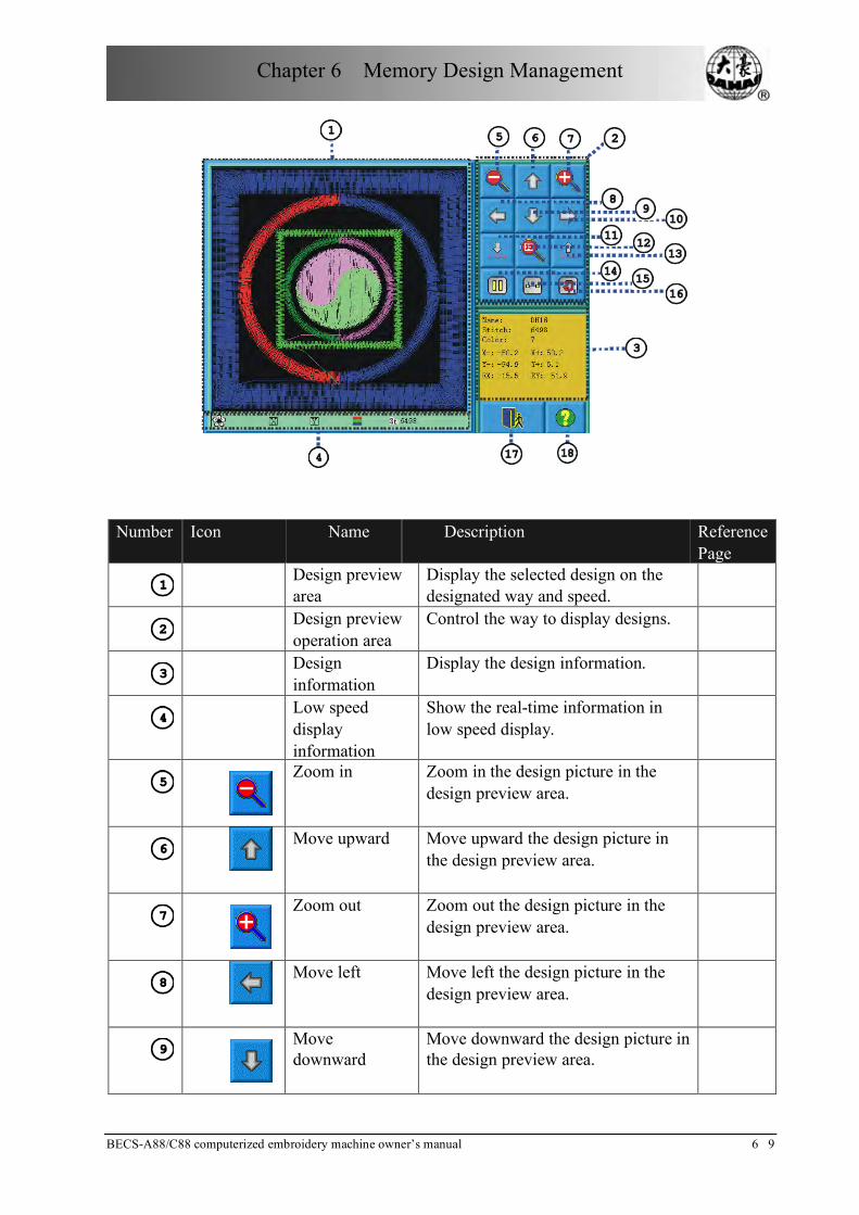
Chapter 6 Memory Design Management
BECS-A88/C88 computerized embroidery machine owner’s manual 6 9
Number Icon Name Description Reference Page
Design preview
area Display the selected design on the designated way and speed.
Design preview
operation area Control the way to display designs.
Design
information Display the design information.
Low speed
display information
Show the real-time information in low speed display.
Zoom in Zoom in the design picture in the design preview area.
Move upward Move upward the design picture in
the design preview area.
Zoom out Zoom out the design picture in the design preview area.
Move left Move left the design picture in the
design preview area.
Move downward
Move downward the design picture in the design preview area.

Chapter 6 Memory Design Management
70 BECS-A88/C88 computerized embroidery machine owner’s manual
Number Icon Name Description Reference Page
Move right Move right the design picture in the design preview area.
Speed down Decelerate the display speed.
Display to the full size
Display the design to the full size in the design preview area.
Speed up Accelerate the display speed.
Draw/halt switch
is for switching between
drawing design and halting the drawing.
Single step display
Draw the design by single step according to clicks.
Redraw the design
Display the selected design again.
Exit Exit the operation in the memory
design preview screen.
Help Display the help menu.
Click in the main screen to enter the memory design management
screen.
Select a design in the memory design image area of the memory design
management screen.
Click in the memory design screen to open the memory design preview
screen.
Click in the design preview area to control the design size.

Chapter 6 Memory Design Management
BECS-A88/C88 computerized embroidery machine owner’s manual 7 1
Click to control the design display position. Click
to control the design display speed. Click to control the
design display and halt. Click to automatically switch to halt for single step
design display. And click to resume normal display. Click to redisplay
the selected design.
6-4 Sorting the designs
To help find the design quickly, the user can sort the memory designs in the
memory design management screen and the designs can be displayed in normal or
reverse order. When the memory designs are more than one page, the current page
will automatically switch to the first page after sorting.
This system supports the following sorting ways: by design stitches, width, height,
name and color number.
The current sorting way is by default shown on the design sorting button. If the
user wants to use another sorting way, click the design sorting button and select
from the following menu and then the memory designs will be sort in the
designated order.
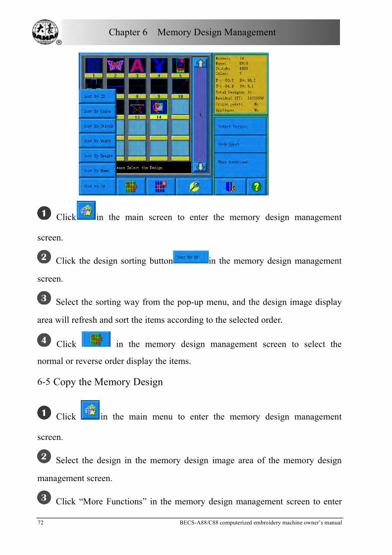
Chapter 6 Memory Design Management
72 BECS-A88/C88 computerized embroidery machine owner’s manual
Click in the main screen to enter the memory design management
screen.
Click the design sorting button in the memory design management
screen.
Select the sorting way from the pop-up menu, and the design image display
area will refresh and sort the items according to the selected order.
Click in the memory design management screen to select the
normal or reverse order display the items.
6-5 Copy the Memory Design
Click in the main menu to enter the memory design management
screen.
Select the design in the memory design image area of the memory design
management screen.
Click “More Functions” in the memory design management screen to enter

Chapter 6 Memory Design Management
BECS-A88/C88 computerized embroidery machine owner’s manual 7 3
the memory design choosing screen.
Click “Copy Design” to enter its operation screen. The system will
automatically provide the available smallest design number and default design
name. If the user doesn’t want to change them, go to directly.
To input a new design number, click “design number” and input the new
number in the pop-up window, and then click to confirm the input.
To input a new design name, click “design name” and input the new name in
the pop-up window, and then click to confirm the input.
Click to carry out the copying operation, and return. Click to
cancel the copying operation, and return.

Chapter 6 Memory Design Management
74 BECS-A88/C88 computerized embroidery machine owner’s manual
6-6 Deleting the memory design
This is to delete one or more designs in the machine memory.
Click in the main menu to enter the memory design management
screen.
Click “More Functions” in the memory design management screen to enter
the memory design choosing operation screen.
Click “Delete Design” to enter its operation screen.
Select the design. The user can choose to select one design for one time or
several designs by switching between and . The screen is similar to
the memory design management screen, in which the designs can also be sorted
and previewed.
Click to carry out deleting and then return to the design operation

Chapter 6 Memory Design Management
BECS-A88/C88 computerized embroidery machine owner’s manual 7 5
choosing screen. Cancel to cancel deleting and return.
6-7 Setting Normal Parameters
Each design has its setting of color-changing order and normal parameters such as
scaling up/down and repetition, which can be checked and set here.
Click in the main menu to enter the memory design management
screen.
Select the design in the memory design image area of the memory design
management screen.
Click “More Functions” to enter the design operation choosing screen.
Click “Normal Para”. If the selected design is the current embroidering
design, the embroidery parameter setting screen will pop up. Please read Chapter
Five for reference.
If the selected design is not the current embroidering design, the non-embroidery
parameter setting screen will pop up.

Chapter 6 Memory Design Management
76 BECS-A88/C88 computerized embroidery machine owner’s manual
For the setting of normal parameters and color-changing, please also read Chapter
5. After setting, click to save the setting with the design for later use.
Click to cancel the setting and return to the design operation choosing
screen.
6-8 “Compile Paras Design”
This is to change the setting of color-changing order and normal parameters such
as scaling up/down and repetition, which is attached to a specific design, so as to
create a new design.
Click in the main menu to enter the memory design management
screen.
Select the design in the memory design image area of the memory design
management screen.
Click “More Functions” to enter the design operation choosing screen.
Click “Compile Paras Design” to enter its operation screen.
If don’t use the default values provided by the system, click “Design

Chapter 6 Memory Design Management
BECS-A88/C88 computerized embroidery machine owner’s manual 7 7
Number” or “Design Name” and input the new number and name.
Click to create a new design and return to the design operation
choosing screen. Click to cancel creating and return.
6-9 Edit Packed Design
The packed design means a design group packed from a certain (less than 99)
memory designs after setting their parameters. The packed design is set as
automatic continuous embroidery. In the memory design management screen the
icon of the packed design is shown as . To embroider a packed design,
return to the memory design management screen after creating or editing the
packed design. If it’s already in the embroidery preparation status, click the
design and “Select Design”, and the system will automatically return to the main
screen. Then after embroidery confirmation, pull the bar for embroidery. The user
can also edit the packed design into the common design by the editing function,
so as to check and embroider the design.
Click in the main menu to enter the memory design management
screen.
To edit a saved packed design, select the packed design first. To create a
packed design, carry out the following operations.
Click “More Functions” to enter the memory operation choosing screen.
Click “Edit Packed Design” to enter its operation screen.
The combined ID shows the current design number and how many designs the
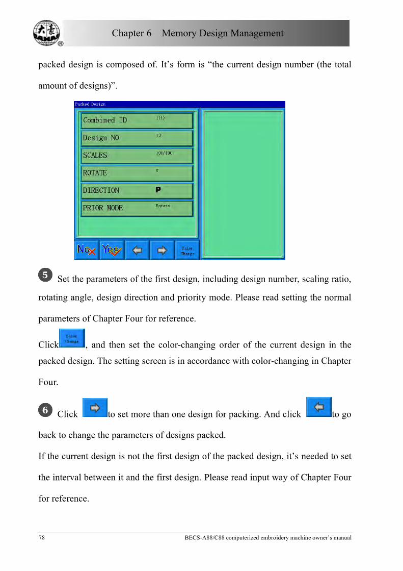
Chapter 6 Memory Design Management
78 BECS-A88/C88 computerized embroidery machine owner’s manual
packed design is composed of. It’s form is “the current design number (the total
amount of designs)”.
Set the parameters of the first design, including design number, scaling ratio,
rotating angle, design direction and priority mode. Please read setting the normal
parameters of Chapter Four for reference.
Click , and then set the color-changing order of the current design in the
packed design. The setting screen is in accordance with color-changing in Chapter
Four.
Click to set more than one design for packing. And click to go
back to change the parameters of designs packed.
If the current design is not the first design of the packed design, it’s needed to set
the interval between it and the first design. Please read input way of Chapter Four
for reference.

Chapter 6 Memory Design Management
BECS-A88/C88 computerized embroidery machine owner’s manual 7 9
Click to save or click to cancel the operation and return to the
design operation choosing screen.
6-10 Programming Combined designs
The action will help to make combined design to normal embroidery design.
Select a combined design.
Click the button on the main menu
Click “more functions” to enter the memory design choosing operation
screen.
Click “Compile Paras Design” to enter its operation screen.
6-11 Setting Patching Embroidery
The system has two ways for patching embroidery: manual moving frame out and
automatic moving frame out.
Manual moving frame out: when embroidering to meet stop code, the machine
will stop automatically. Move the frame to the proper position for patching with

Chapter 6 Memory Design Management
80 BECS-A88/C88 computerized embroidery machine owner’s manual
the manual frame-moving button. Then click and to return to the stop
point. At last pull the bar for embroidery.
Automatic moving frame out has two ways: moving frame to the offset point and
setting the moving distance. The operation is as follows: First set patching
embroidery function for the design. Then when embroidering to the patching
point, the machine moves to the offset point (which has to be set) or move out
according to the set distance. After patching pull the bar and the machine will
automatically return to the stop point to continue embroidery.
The following is how to add patching embroidery to the design:
Click in the main menu to enter the memory design management
screen.
Select the design in the memory design image area of the memory design
management screen.
Click “More Functions” to enter the design operation choosing screen.
Click “Add Patch Code to Design” to enter into “patching setting operation”
screen.
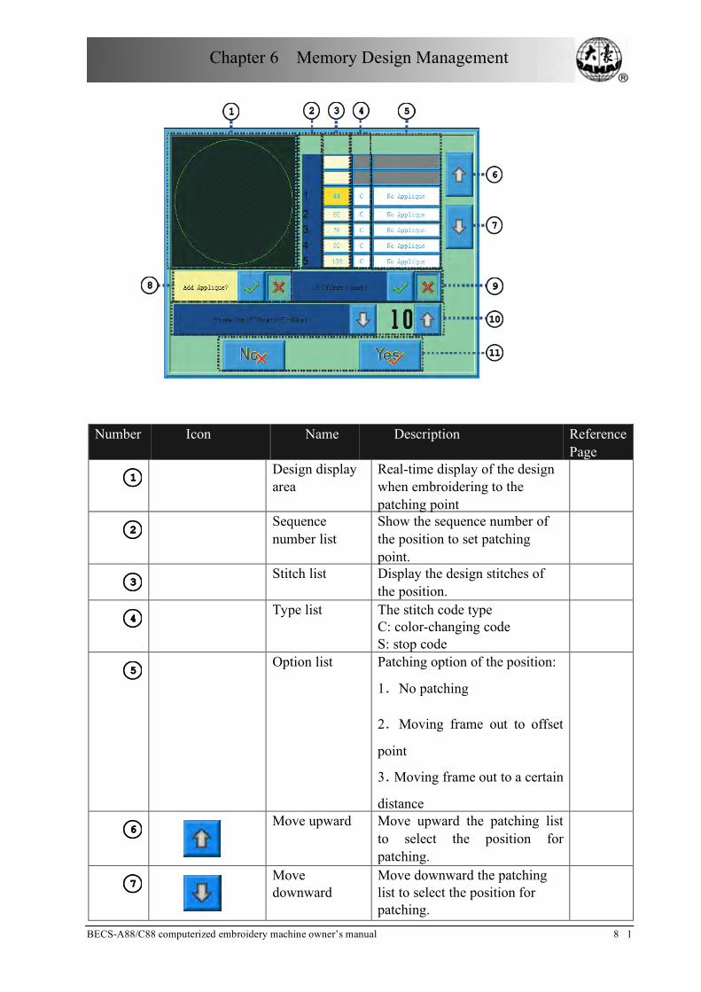
Chapter 6 Memory Design Management
BECS-A88/C88 computerized embroidery machine owner’s manual 8 1
Number Icon Name Description Reference Page
Design display
area Real-time display of the design when embroidering to the patching point
Sequence
number list Show the sequence number of the position to set patching point.
Stitch list Display the design stitches of
the position.
Type list The stitch code type
C: color-changing code S: stop code
Option list Patching option of the position:
1.No patching
2.Moving frame out to offset
point
3.Moving frame out to a certain
distance
Move upward Move upward the patching list to select the position for patching.
Move downward
Move downward the patching list to select the position for patching.
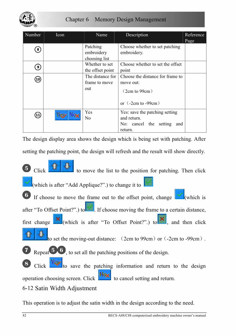
Chapter 6 Memory Design Management
82 BECS-A88/C88 computerized embroidery machine owner’s manual
Number Icon Name Description Reference Page
Patching
embroidery choosing list
Choose whether to set patching embroidery.
Whether to set
the offset point Choose whether to set the offset point
The distance for
frame to move out
Choose the distance for frame to move out:
(2cm to 99cm)
or(-2cm to -99cm)
Yes No
Yes: save the patching setting and return. No: cancel the setting and return.
The design display area shows the design which is being set with patching. After
setting the patching point, the design will refresh and the result will show directly.
Click to move the list to the position for patching. Then click
(which is after “Add Applique?”.) to change it to
If choose to move the frame out to the offset point, change (which is
after “To Offset Point?”.) to . If choose moving the frame to a certain distance,
first change (which is after “To Offset Point?”.) to , and then click
to set the moving-out distance: (2cm to 99cm)or(-2cm to -99cm).
Repeat , to set all the patching positions of the design.
Click to save the patching information and return to the design
operation choosing screen. Click to cancel setting and return.
6-12 Satin Width Adjustment
This operation is to adjust the satin width in the design according to the need.

Chapter 6 Memory Design Management
BECS-A88/C88 computerized embroidery machine owner’s manual 8 3
Click in the main menu to enter the memory design management
screen.
Select the design in the memory design image area of the memory design
management screen.
Click “More Functions” to enter the design operation choosing screen.
Click “Adjust Width” to enter its operation screen.
If don’t use the default values, click the design number and design name and
change them.
Click “X Adjust” to input the new value, and then click to confirm it.
Click “Y Adjust” to input the new value, and then click to confirm it.
Click to adjust the satin width and save it as a new design to return to
the design operation choosing screen. Click to cancel the setting and return.
6-13 Shift the Frame to Make a New Design
The user often wants to embroider the boundary of a design before embroidering
it, so as to help later patching. The function of “Shift the frame to make a new
design” can create such a design, and you can select the new design to embroider

Chapter 6 Memory Design Management
84 BECS-A88/C88 computerized embroidery machine owner’s manual
the boundary.
In embroidery preparation status, stop the frame to the point, from which the
design will be embroidered.
Click in the main menu to enter the memory design management
screen.
Click “More Functions” to enter the design operation choosing screen.
Click “Frame to Make Design” to enter into operation screen.
Click to very between satin stitch and jump stitch. Click the
manual frame-moving key to move the frame along the desired route. Click
at every turning point to confirm the trace.
Click after editing, and the system will prompt to input the new
design number.
According to the prompt, input the number of the new design (The computer
will provide a number for choice) and design name. Click to create the new

Chapter 6 Memory Design Management
BECS-A88/C88 computerized embroidery machine owner’s manual 8 5
design.
Click to cancel the setting and return.
6-14 “Make True Design Range”
This function is to create a new design according to the outline of the designated
design.
Click in the main menu to enter the memory design management
screen.
Select the design in the memory design image area of the memory design
management screen.
Click “More Functions” to enter the design operation choosing screen.
Click “Make True Design Range” to enter its operation screen.
If don’t use the default values, click the design number and design name and
change them.
Click to create a design and return to the design operation choosing
screen. Click to cancel the setting and return.
6-15 “Hi-Speed Design”
Click in the main menu to enter the memory design management
screen.
Select the design in the memory design image area of the memory design
management screen.
Click “More Functions” to enter the design operation choosing screen.

Chapter 6 Memory Design Management
86 BECS-A88/C88 computerized embroidery machine owner’s manual
Click “Hi-Speed Design” to enter its operation screen.
If don’t use the default values, click the design number and design name and
change them.
Click to create Hi-Speed Design and return to the design operation
choosing screen. Click to cancel the setting and return.
6-16 Divide the Design
Click in the main menu to enter the memory design management
screen.
Select the design in the memory design image area of the memory design
management screen.
Click “More Functions” to enter the design operation choosing screen.
Click “Divide” to enter its operation screen.
If don’t use the default values, click the design number and design name and
change them.
Click “Split Stitches” to input stitch value and click to confirm.
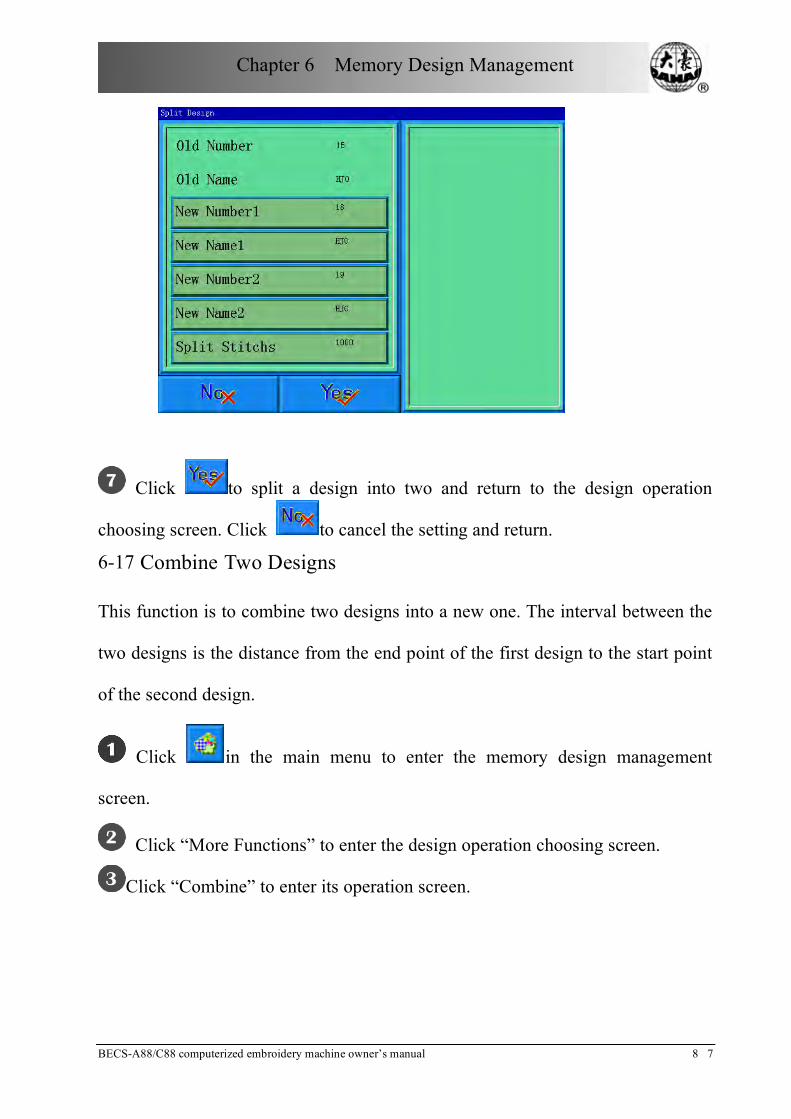
Chapter 6 Memory Design Management
BECS-A88/C88 computerized embroidery machine owner’s manual 8 7
Click to split a design into two and return to the design operation
choosing screen. Click to cancel the setting and return.
6-17 Combine Two Designs
This function is to combine two designs into a new one. The interval between the
two designs is the distance from the end point of the first design to the start point
of the second design.
Click in the main menu to enter the memory design management
screen.
Click “More Functions” to enter the design operation choosing screen.
Click “Combine” to enter its operation screen.
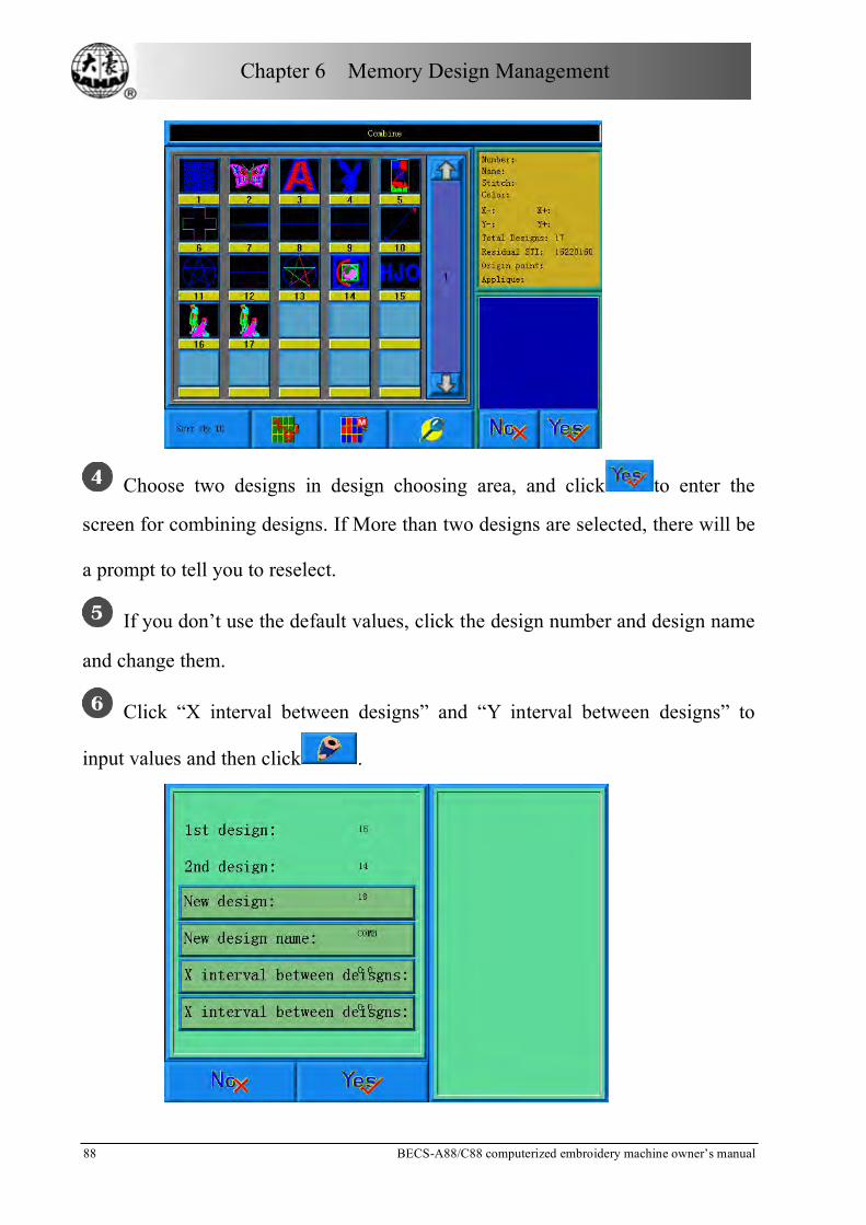
Chapter 6 Memory Design Management
88 BECS-A88/C88 computerized embroidery machine owner’s manual
Choose two designs in design choosing area, and click to enter the
screen for combining designs. If More than two designs are selected, there will be
a prompt to tell you to reselect.
If you don’t use the default values, click the design number and design name
and change them.
Click “X interval between designs” and “Y interval between designs” to
input values and then click .

Chapter 6 Memory Design Management
BECS-A88/C88 computerized embroidery machine owner’s manual 8 9
Click to combine and return to the design operation choosing screen.
Click to cancel the setting and return.
6-18 Clear all Memory Designs
This function is to clear all the designs in the memory. Be cautious to use it.
Click in the main menu to enter the memory design management
screen.
Click “More Functions” to enter the design operation choosing screen.
Click “Clear All”, and a confirmation window will pop up.
Click to clear all the designs and return to the design operation
choosing screen. Click to cancel clearing and return.

Chapter 7 Memory Design Edit
90 BECS-A88/C88 computerized embroidery machine owner’s manual
Chapter 7 Memory Design Edit
You can edit common designs smaller than 100000 needles in the memory
through this function, or establish a new design.
7-1 Start Editing Design
Choose the design that will edit in the window of memory design management,
then click “More Functions” key.
choose the pattern click More Functions¡°¡±
In “choose operation of the memory design”, click “design edit” key, after which,
in pop-up confirm dialog box, pick out "Yes" to start edit the design selected at
present; Click "No" edits a new design. (Note: the design selected can not be
combined design, or system will warn “not common design”)

Chapter 7 Memory Design Edit
BECS-A88/C88 computerized embroidery machine owner’s manual 9 1
pick out " Ye s" to start edit
the patter n sel ected at presentClick "No" edits a new pattern
7-2 Pattern Edits Operation
7.2.1 Summarize
Pattern preview window
Document and view operation
Needle check orientation front-panel
Needle edit funtion key
Needle information
Pattern preview window: use for preview pattern. In view, use “+”mark the
position of current needle. The needle trace of current stitch use white and
outstanding manifestation.
Document and view operation: Use for save pattern, withdraw and looking into

Chapter 7 Memory Design Edit
92 BECS-A88/C88 computerized embroidery machine owner’s manual
the help, and zoom view function.
Needle check orientation front-panel: use for orient “current needle” (needle that
need check and edit).
Needle edit function key: use for switch stitch code, insert needle, delete needle
and move the needle position.
Needle information: Use for information about total stitch amount, serial number、
position and type of current needle.
7.2.2 Document and View Operation
Keep the current pattern to a new document.
Reduce the pattern thus can see the all of the pattern. If the pattern size is
smaller than show scope of the screen, then show the pattern with the actual size.
Enlarge the pattern to 450% to thus look into the detail of the needle
vestige." Current needle" will move the middle position of the screen
automatically.
Enlarge or zoom view. The scaling is 150% every time.
Withdraw the pattern editor function.
Look into online help of the pattern edit operation screen.
7.2.3 Orient Needle
Establish" current needle" arrives some one needle. At the same time, use “+”to
mark the position of “current needle” in the window of pattern preview. If there is
no “current needle" show in the view, so the system will renew the view
automatically, and show “current needle" in the centre of view.

Chapter 7 Memory Design Edit
BECS-A88/C88 computerized embroidery machine owner’s manual 9 3
Move backward 1/10/100/1000 needles.
Move forward 1/10/100/1000 needles.
Move to the next change color code. Move to the previous change
color code.
Move to the next jump stitch. Move to the previous jump stitch..
Move to the last stitch. Move to the first stitch.
Move to the previous or next appointed stitch code. Click the key in
centre, can choose the type of stitch that need checked.
7.2.4 Convert Needle Code
After orient some one needle, click key and can convert the type of that
needle.
Include X/Y position needle for move, such as stain stitch、jump stitch、send
sequin etc., the needle code type can convert mutually.
Don't include X/Y position needle for move, such as switch of sequin﹑stop
code、change color code etc., the needle code type can convert mutually.
7.2.5 Insert Needle
Click key can insert a new needle code after current needle.
If the current needle is the last one needle of the pattern, so the insert position of
new needle is the excursion of current needle with same direction and same
distance.
If the current needle in the middle of pattern, so the new needle insert at the
middle position of current needle and next needle.
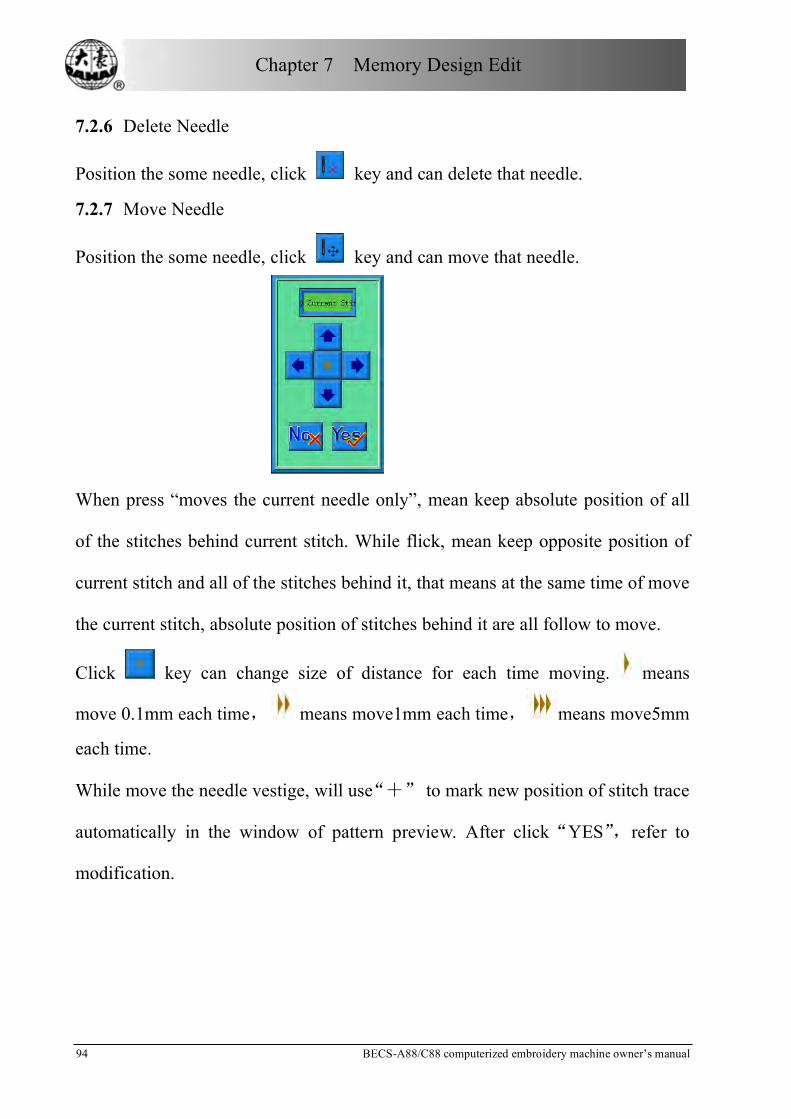
Chapter 7 Memory Design Edit
94 BECS-A88/C88 computerized embroidery machine owner’s manual
7.2.6 Delete Needle
Position the some needle, click key and can delete that needle.
7.2.7 Move Needle
Position the some needle, click key and can move that needle.
When press “moves the current needle only”, mean keep absolute position of all
of the stitches behind current stitch. While flick, mean keep opposite position of
current stitch and all of the stitches behind it, that means at the same time of move
the current stitch, absolute position of stitches behind it are all follow to move.
Click key can change size of distance for each time moving. means
move 0.1mm each time, means move1mm each time, means move5mm
each time.
While move the needle vestige, will use“+” to mark new position of stitch trace
automatically in the window of pattern preview. After click“YES”,refer to
modification.

Chapter 8 Letter Design
BECS-A88/C88 computerized embroidery machine owner’s manual 9 5
Chapter 8 Letter Design
You can through the letterform storage that saved in system, to create pattern file
based on letter.
8-1 Enter “Create Letter Pattern” Function
Click pattern management key on main screen, enter into pattern
management screen.
Click “select other operations” to enter into pattern operation select screen.

Chapter 8 Letter Design
96 BECS-A88/C88 computerized embroidery machine owner’s manual
Click “create letter pattern” key, then can enter into parameter enter screen of
letter embroidery.
8-2 Enter Embroidery Letter Bunch and Basic Parameter
After open the window of parameter input, enter into letter input screen
automatically.
The left of window is parameter list window; the right is parameter input window.
After click one of parameter in left list, then will open the input window of this
parameter in the right window. After adjust value of one of parameter, need click
key to save it.

Chapter 8 Letter Design
BECS-A88/C88 computerized embroidery machine owner’s manual 9 7
“Letter bound”: means the letter list that will be embroidery
“Letterform”: means the letterform that use for embroidering letter. The
letterform was selected here will use for all of letters, if need set letterform for
individual letter, please do operation in “letter pattern adjust screen”.
“Rank method”: the rank method of letter. Total support four rank methods,
including “plane” “vertical” “up arc” “down arc”.
“Letter space”: means rank space between letters, the unit is 0.1mm.
“Letter angle”: means when rank method as round arc, whether the angle of the
each letter will change follows behind the position of round arc.
“Letter bound rotate angle”: means rotate angle for whole letter bound.
“Letter high zoom”: means increase or reduce letter high.
“Letter width zoom”: means increase or reduce letter width.
“Stain stitch density”: means distance between each stitch of born letter pattern.
The value is smaller, the density is bigger.
“Character rotate angle”: means rotate angle of each letter that opposite to centre
of it selves.
“Change color automatically”: whether add change color code before each letter.
After establishing letter pattern parameter, click key, enter window of”
letter pattern adjust”. Click key withdraw the function of letter pattern.
8-3 Adjust Letter Pattern
“Letter pattern adjust” screen
“Letter pattern adjust” screen is shown as diagram:

Chapter 8 Letter Design
98 BECS-A88/C88 computerized embroidery machine owner’s manual
The operation key is divided into three parts in the screen, the left side is the
article and view function key, under is letter rank adjustment key (for whole
rank) , right side is the adjustment key for picked letter. The centre of screen is the
area to show letter pattern.
Under general circumstance, should set whole rank method of letter bound, rotate
angle, letter space etc. parameters (key is under operation screen); Pick out again
the particular letter, adjust rank parameter of individual letter (key is in right side
of operation screen).
Letter pattern manifestation window: the central cross mean coordinate,
intersection is origin(0,0). The letter rank surrounds origin automatically.
View and file operation
“Needle trace”: show/hide needle trace, hide needle trace can improve
operation speed.
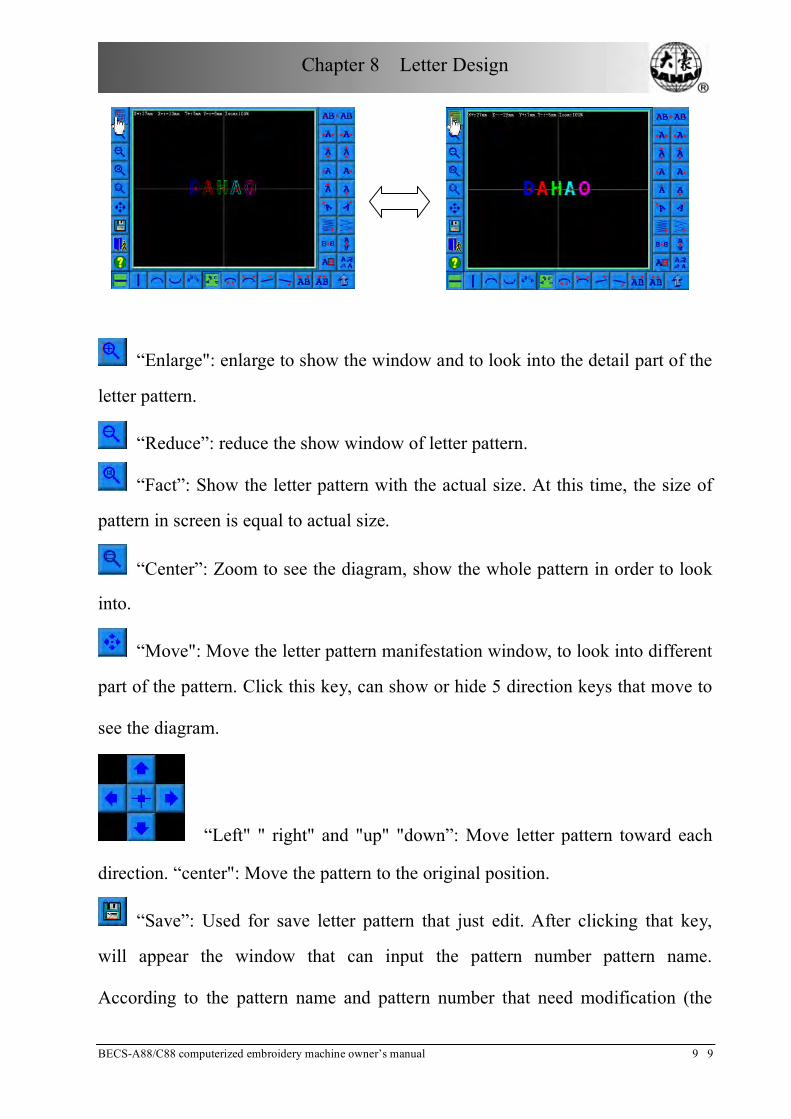
Chapter 8 Letter Design
BECS-A88/C88 computerized embroidery machine owner’s manual 9 9
“Enlarge": enlarge to show the window and to look into the detail part of the
letter pattern.
“Reduce”: reduce the show window of letter pattern.
“Fact”: Show the letter pattern with the actual size. At this time, the size of
pattern in screen is equal to actual size.
“Center”: Zoom to see the diagram, show the whole pattern in order to look
into.
“Move": Move the letter pattern manifestation window, to look into different
part of the pattern. Click this key, can show or hide 5 direction keys that move to
see the diagram.
“Left" " right" and "up" "down”: Move letter pattern toward each
direction. “center": Move the pattern to the original position.
“Save”: Used for save letter pattern that just edit. After clicking that key,
will appear the window that can input the pattern number pattern name.
According to the pattern name and pattern number that need modification (the

Chapter 8 Letter Design
100 BECS-A88/C88 computerized embroidery machine owner’s m a n u a l
serial number does not modification generally), then click confirmation to start
keep.
“Withdraw": Withdraw" establish letter pattern" function screen.
“Help": Online help of “letter pattern adjust” screen.
Adjust key of whole rank parameter
If after you edit individual letter, then again to adjust whole rank parameter, the
editor of the individual letter will be probably overlay.
"Level": Rank the letter bound by level method. Have totally 4 kinds of
arrange way, when select one of rank method, the opposite key will present press
down status..
“Vertical”: rank letter bound by vertical method.

Chapter 8 Letter Design
BECS-A88/C88 computerized embroidery machine owner’s manual 1 0 1
“Up arc”: rank letter bound by round arc method with up bend.
“Down arc”: rank letter bound by round arc method with down bend.
"Fix the letter direction": When rank the letter bound by round arc method,
the letter angle not change with the position of round arc, but be equal to a
certain angle fixedly.
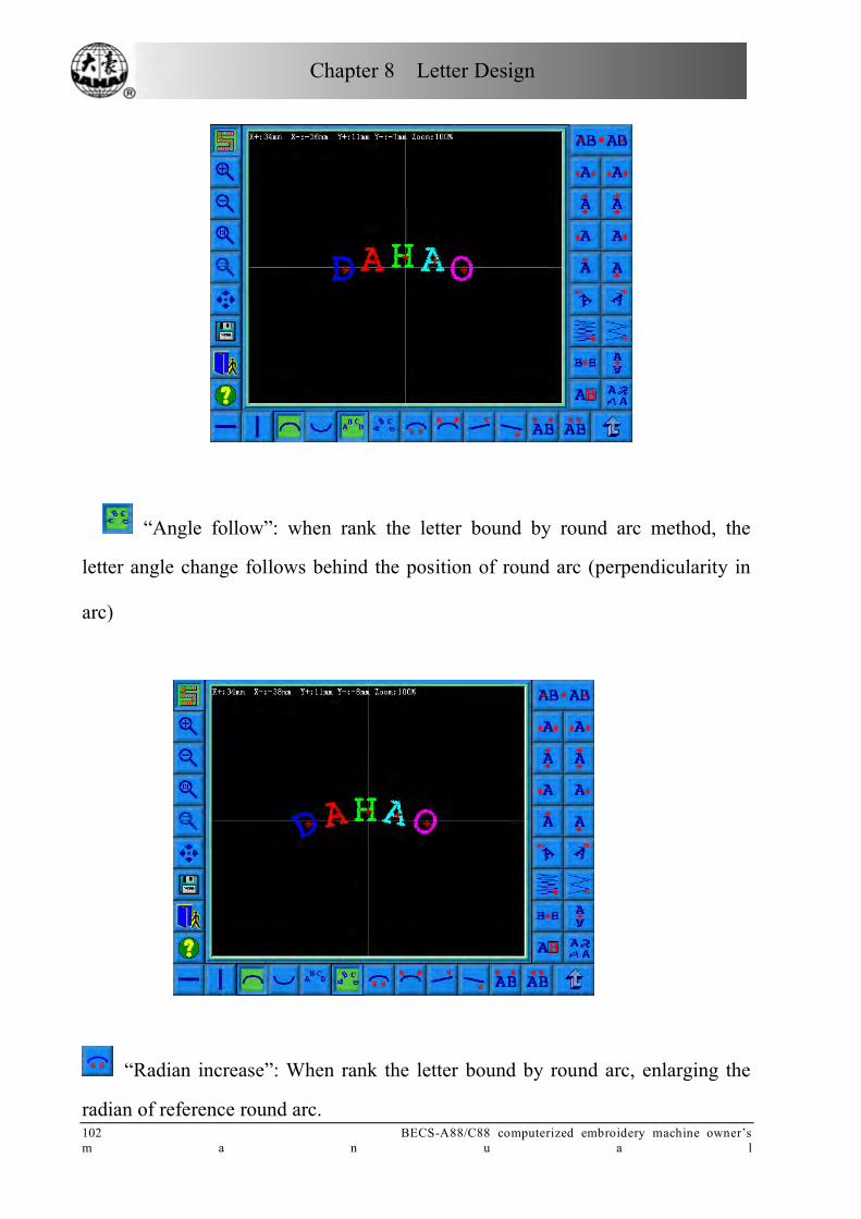
Chapter 8 Letter Design
102 BECS-A88/C88 computerized embroidery machine owner’s m a n u a l
“Angle follow”: when rank the letter bound by round arc method, the
letter angle change follows behind the position of round arc (perpendicularity in
arc)
“Radian increase”: When rank the letter bound by round arc, enlarging the
radian of reference round arc.

Chapter 8 Letter Design
BECS-A88/C88 computerized embroidery machine owner’s manual 1 0 3
“Radian reduces”: When rank the letter bound by round arc, reduce the
radian of reference round arc.
“Whole anticlockwise rotate”: anticlockwise rotate for whole letter bound.
“Whole clockwise rotate”: clockwise rotate for whole letter bound.
"Extend letter space”: Increase the distance between the letter.

Chapter 8 Letter Design
104 BECS-A88/C88 computerized embroidery machine owner’s m a n u a l
“Reduce letter space”: reduce space between letters.
Pick out letter adjustment key
“Select switch”: switch selected letter. Must pick out a certain letter and
then can carry on the editor for it. When there is a red“+”in the center of letter,
meaning the letter to is pick out, such as: . The system default will pick out all
letters. After click “select switch” key, pick out the first letter, then click, pick out
the second, depend on this kind to push. After picking out the end letter, then
click “select switch”, will pick out all letters again.
“Increase width": increase width of selected letter. Such as:
“Reduce width”: reduce width of selected letter. Such as:
“Increase height”: increase height of selected letter. Such as:
“Reduce height”: reduce height of selected letter. Such as:
“Left move”: Move the selected letter toward left side. Such as:
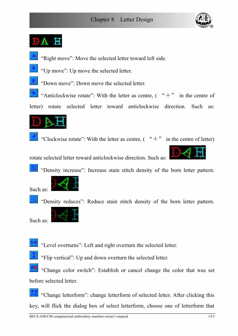
Chapter 8 Letter Design
BECS-A88/C88 computerized embroidery machine owner’s manual 1 0 5
“Right move”: Move the selected letter toward left side.
“Up move”: Up move the selected letter.
“Down move”: Down move the selected letter.
“Anticlockwise rotate”: With the letter as centre, ( “+” in the centre of
letter) rotate selected letter toward anticlockwise direction. Such as:
“Clockwise rotate”: With the letter as centre, ( “+” in the centre of letter)
rotate selected letter toward anticlockwise direction. Such as:
“Density increase”: Increase stain stitch density of the born letter pattern.
Such as:
“Density reduces”: Reduce stain stitch density of the born letter pattern.
Such as:
“Level overturns”: Left and right overturn the selected letter.
“Flip vertical”: Up and down overturn the selected letter.
“Change color switch”: Establish or cancel change the color that was set
before selected letter.
“Change letterform”: change letterform of selected letter. After clicking this
key, will flick the dialog box of select letterform, choose one of letterform that
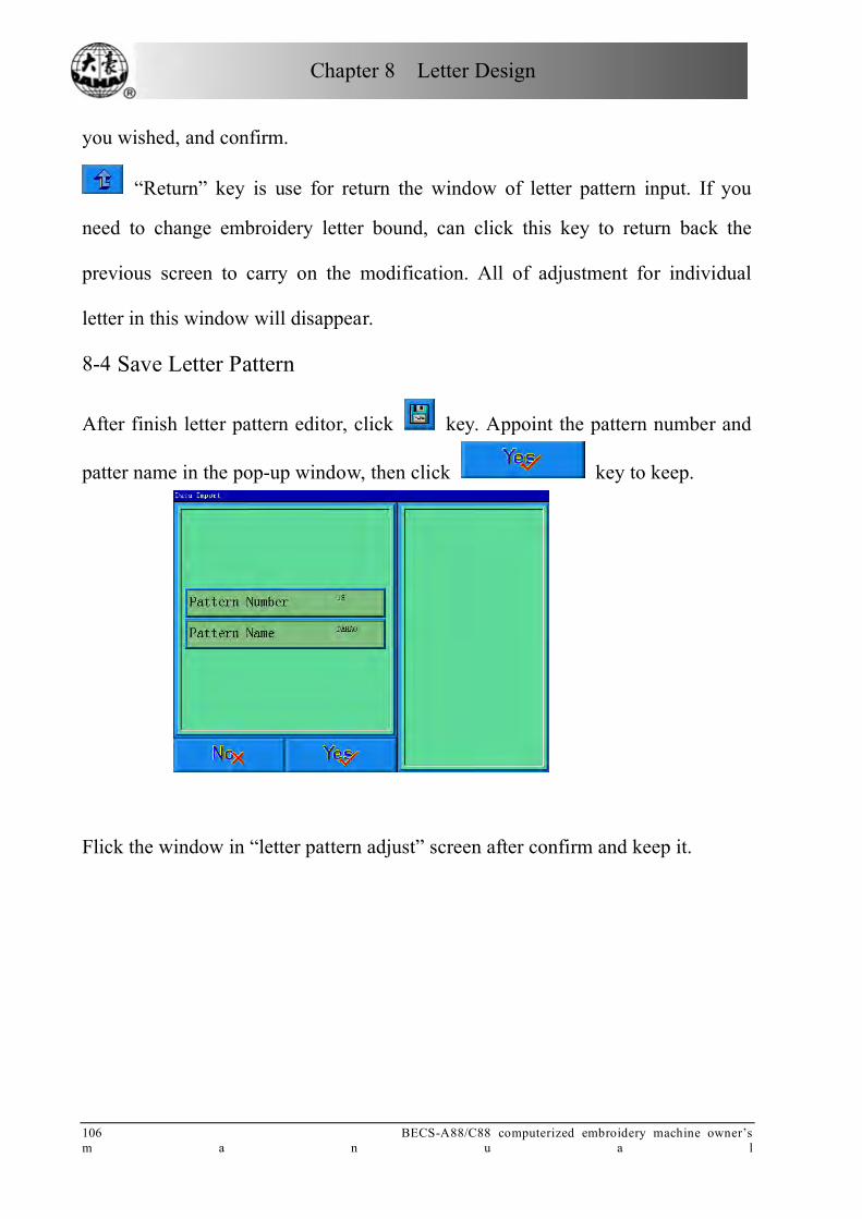
Chapter 8 Letter Design
106 BECS-A88/C88 computerized embroidery machine owner’s m a n u a l
you wished, and confirm.
“Return” key is use for return the window of letter pattern input. If you
need to change embroidery letter bound, can click this key to return back the
previous screen to carry on the modification. All of adjustment for individual
letter in this window will disappear.
8-4 Save Letter Pattern
After finish letter pattern editor, click key. Appoint the pattern number and
patter name in the pop-up window, then click key to keep.
Flick the window in “letter pattern adjust” screen after confirm and keep it.
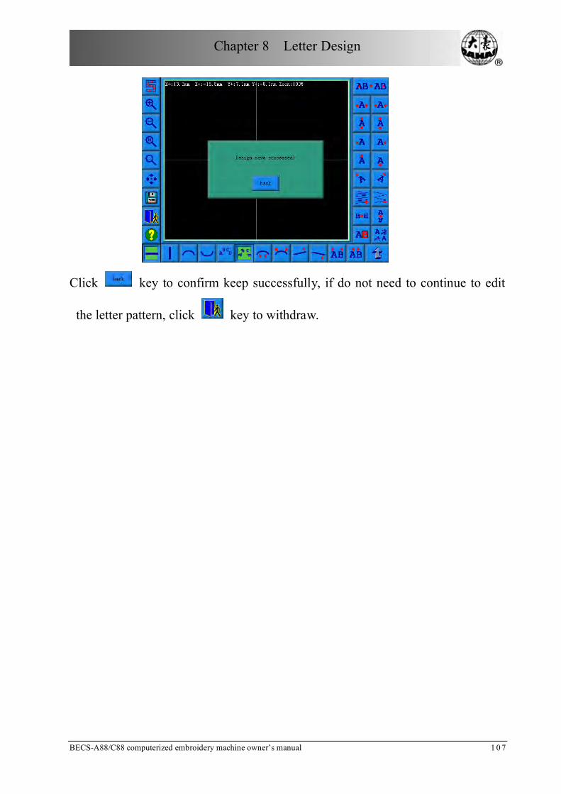
Chapter 8 Letter Design
BECS-A88/C88 computerized embroidery machine owner’s manual 1 0 7
Click key to confirm keep successfully, if do not need to continue to edit
the letter pattern, click key to withdraw.

Chapter 9 Assistant Operation Functions
108 BECS-A88/C88 computerized embroidery machine owner’s m a n u a l
Chapter 9 Assistant Operation Functions
These functions are carried out by clicking the keys on the Assistant Operation
screen.
Click to enter the Assistant Operation screen.
Number Icon Name Description Reference
Page
Last page Turn to last page.
Next page Turn to next page.
Information
area Show error messages.
Exit Exit the assistant operation screen and
return to the main screen.
Key list The list of function keys of assistant
operation
The functions are so much that the function keys take two pages. Click and
to switch between the two pages.
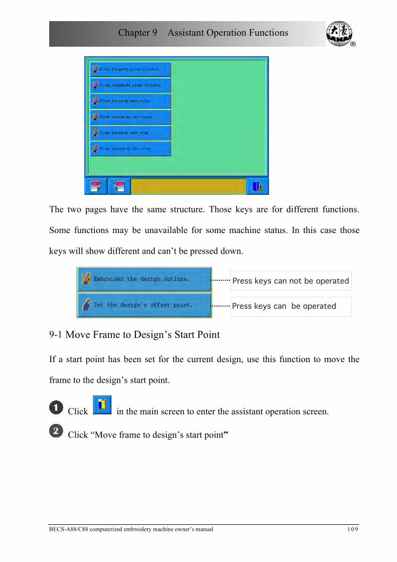
Chapter 9 Assistant Operation Functions
BECS-A88/C88 computerized embroidery machine owner’s manual 1 0 9
The two pages have the same structure. Those keys are for different functions.
Some functions may be unavailable for some machine status. In this case those
keys will show different and can’t be pressed down.
Press keys can not be operated
Press keys can be operated
9-1 Move Frame to Design’s Start Point
If a start point has been set for the current design, use this function to move the
frame to the design’s start point.
Click in the main screen to enter the assistant operation screen.
Click “Move frame to design’s start point”

Chapter 9 Assistant Operation Functions
110 BECS-A88/C88 computerized embroidery machine owner’s m a n u a l
Click
The system moves the frame to the design’s start point.
9-2 Saving the Start Point
If the origin point of the frame is already set (refer to “Setting Frame Protection
when Power-off”, Chapter Ten), the machine can save the start point of the current
design at the embroidery preparation status or before embroidering.
Move the frame to the start point.
Click in the main screen to enter the assistant operation screen.
Click “Save the design’s start point”.
A prompt window will pop up.
Click to save the current frame position as the design’s start point.
Click to cancel the above operation.

Chapter 9 Assistant Operation Functions
BECS-A88/C88 computerized embroidery machine owner’s manual 1 1 1
9-3 “Move Frame to Let Design Be Central”
This function is to move frame to position the design at the center of frame
software protection, so as to embroider the design at the center of the frame. (See
“Setting the Frame’s Software Protection”, Chapter Ten)
Click in the main screen to enter the assistant operation screen.
Click “Move frame to let design be central”.
The system asks the user to confirm.

Chapter 9 Assistant Operation Functions
112 BECS-A88/C88 computerized embroidery machine owner’s m a n u a l
Click to confirm and the system will calculate and move the frame.
Click to cancel the above operation.
The system returns to the main screen.
9-4 Show the Range of Embroidery Design
This function is to show the boundary information of a design.
Click in the main screen to enter the assistant operation screen.
Click “Show the range of embroidery design”.
The system will show the concerned information.
The system shows the boundary information.
Click to close the window.
9-5 Move Frame along the Design Range
This function is to move the frame along the design range to check if the design
exceeds the limits. When the frame meets the limits during this process, the
system has the self-correcting ability.
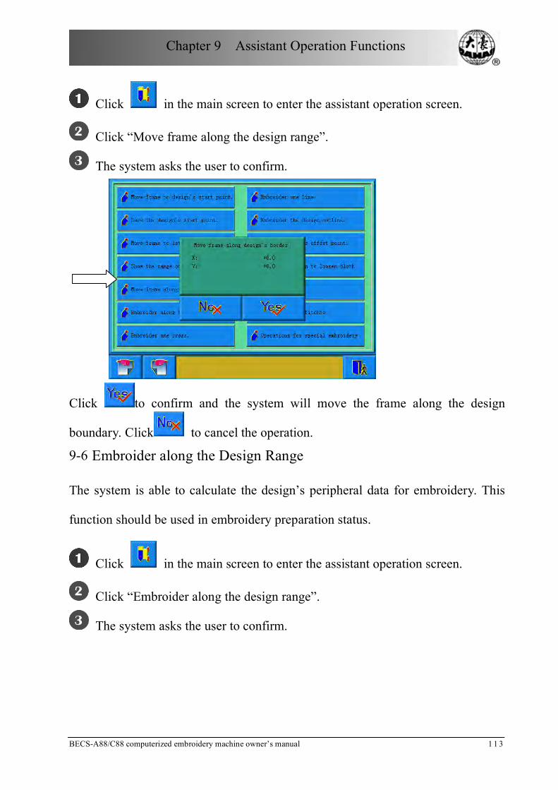
Chapter 9 Assistant Operation Functions
BECS-A88/C88 computerized embroidery machine owner’s manual 1 1 3
Click in the main screen to enter the assistant operation screen.
Click “Move frame along the design range”.
The system asks the user to confirm.
Click to confirm and the system will move the frame along the design
boundary. Click to cancel the operation.
9-6 Embroider along the Design Range
The system is able to calculate the design’s peripheral data for embroidery. This
function should be used in embroidery preparation status.
Click in the main screen to enter the assistant operation screen.
Click “Embroider along the design range”.
The system asks the user to confirm.

Chapter 9 Assistant Operation Functions
114 BECS-A88/C88 computerized embroidery machine owner’s m a n u a l
Click to confirm or click to cancel the operation.
The system will calculate the design’s peripheral data and enter the
embroidery confirmation status and the main screen.
The main screen will show . The user pulls bar to embroider the design range.
After finishing it, the system will automatically come back to embroidery
preparation status.
9-7 Embroider one Cross
The system can embroider a cross at the current position, whose size can be
adjusted according to the input.
Click in the main screen to enter the assistant operation screen.
Click “Embroider one Cross”.
The system will enter the setting screen for embroidering one cross.
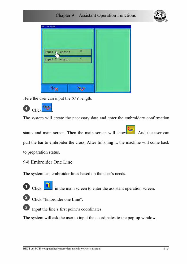
Chapter 9 Assistant Operation Functions
BECS-A88/C88 computerized embroidery machine owner’s manual 1 1 5
Here the user can input the X/Y length.
Click .
The system will create the necessary data and enter the embroidery confirmation
status and main screen. Then the main screen will show . And the user can
pull the bar to embroider the cross. After finishing it, the machine will come back
to preparation status.
9-8 Embroider One Line
The system can embroider lines based on the user’s needs.
Click in the main screen to enter the assistant operation screen.
Click “Embroider one Line”.
Input the line’s first point’s coordinates.
The system will ask the user to input the coordinates to the pop-up window.

Chapter 9 Assistant Operation Functions
116 BECS-A88/C88 computerized embroidery machine owner’s m a n u a l
The user uses the manual frame-moving key on the panel to move the frame to the
start point of the line, and clicks to input the coordinates.
Input the line’s second point’s coordinates.
The system will ask the user to input the coordinates.
The user uses the manual frame-moving key on the panel to move the frame to the
end point of the line, and clicks to input the coordinates.

Chapter 9 Assistant Operation Functions
BECS-A88/C88 computerized embroidery machine owner’s manual 1 1 7
The system will create the necessary data, enter the embroidery confirmation
status and return to the main screen.
The main screen will show . And the user can pull the bar to embroider the
line. After finishing it, the machine will come back to preparation status.
9-9 Embroider the Design’s Outline
Click in the main screen to enter the assistant operation screen.
Click “Embroider the Design’s Outline”.
The system will calculate and wait for the user to confirm.
The system will calculate the outline data and ask the user to confirm the above
operation. Click to confirm or click to cancel the operation.
The system will return to the main screen and embroidery confirmation
status.
The main screen will show . And the user can pull the bar to embroider the

Chapter 9 Assistant Operation Functions
118 BECS-A88/C88 computerized embroidery machine owner’s m a n u a l
outline. After finishing it, the machine will come back to preparation status.
9-10 Set the Offset Point
The offset point can be set at any point other than the start point. After setting it
and beginning to embroider, the frame will first move from the offset point to the
tart point and start normal embroidery. After embroidery, the frame will move
back to the offset point. Moreover the offset point is also necessary for frame to
move out when patching. The function can only be used under the embroidery
confirmation status and before embroidering.
Click in the main screen to enter the assistant operation screen.
Click “Set the design’s offset point”.
Move the frame to the offset point
The system will ask the user to confirm and input the coordinates of X and Y.
Press the frame-moving key to move the frame to the offset point and click
to confirm. Or click to cancel the operation.
The system will save the position of the offset point and return to the main

Chapter 9 Assistant Operation Functions
BECS-A88/C88 computerized embroidery machine owner’s manual 1 1 9
screen.
9-11 Let Needle Down
(The needle stops at the designated low position)
This function is intended for quilt embroidering. In embroidering, the needle will
stop and prick into the embroidery cloth to fix it. After releasing the cloth, move
the frame to the designated position. When the cloth is fixed on the frame again, It
is ready for the next operation.
Click in the main screen to enter the assistant operation screen.
Click “Let needle down to loosen cloth”.
Confirm the operation.
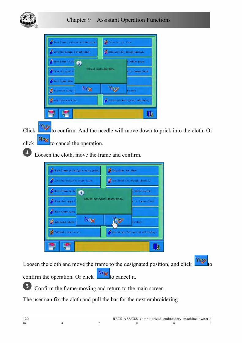
Chapter 9 Assistant Operation Functions
120 BECS-A88/C88 computerized embroidery machine owner’s m a n u a l
Click to confirm. And the needle will move down to prick into the cloth. Or
click to cancel the operation.
Loosen the cloth, move the frame and confirm.
Loosen the cloth and move the frame to the designated position, and click to
confirm the operation. Or click to cancel it.
Confirm the frame-moving and return to the main screen.
The user can fix the cloth and pull the bar for the next embroidering.

Chapter 9 Assistant Operation Functions
BECS-A88/C88 computerized embroidery machine owner’s manual 1 2 1
9-12 Clearing X and Y Displacements
This is to clear the X and Y displacements.
Click in the main screen to enter the assistant operation screen.
Click “Clear X-Y disp”.
The system will set the X and Y values to 0.
The user can check the values in the main screen.
9-13 Clear Overall Stitches
Clear the current embroidered stitches.
Click in the main screen to enter the assistant operation screen.
Click “Clear Overall Stitches”.

Chapter 9 Assistant Operation Functions
122 BECS-A88/C88 computerized embroidery machine owner’s m a n u a l
The system will set the value to 0.
9-14 Operation on AFC, Squin and Coiling Devices
Click in the main screen to enter the assistant operation screen.
Click “Operate for special embroidery”.
Operate according to the prompts.
9-15 Positioning Idling
According to the user’s needs, this function enables the frame to the designated
position without embroidering. Then the user can set the positioning idling of
needle number, color-changing code and stop code.
Acco
rding to the order showed above, from the main screen to enter the positioning

Chapter 9 Assistant Operation Functions
BECS-A88/C88 computerized embroidery machine owner’s manual 1 2 3
idling screen, where there is a list of function keys. The function is available in
embroidery confirmation status.
9.15.1 “Float forward given stitches”
Click in the main screen to enter the assistant operation screen.
Click “Float forward given stitches”.
Input the forward stitches needed.
The system enters the “Machine Do Float” screen and asks the user to input
stitches. Click to confirm or click to cancel the operation.
The system returns to the main screen. Pull the bar right to move the
designated stitches.
9.15.2 “Float backward given stitches”
The operations are similar to that for “Float forward given stitches” except pulling
the bar left.

Chapter 9 Assistant Operation Functions
124 BECS-A88/C88 computerized embroidery machine owner’s m a n u a l
9.15.3 “Float forward next color”
Click in the main screen to enter the assistant operation screen.
Click “Float forward next color”.
Confirm.
The system will return to the main screen. Pull the bar right to move to the
next color-changing code.
The other three functions are similar to this.
9-16 Setting point B
This function is selected and the user must customize.
This function is developed to solve the problem of inconvenience of threading
when thread break appears on giant machine.
When thread break appears, press the slow switch to let the machine trim, then the
frame will move to the point B. After reloading the thread, you can pull bar to the
right side to let the frame back to the stop point. Then proceed embroidering.

Chapter 9 Assistant Operation Functions
BECS-A88/C88 computerized embroidery machine owner’s manual 1 2 5
9.16.1 Setting Course
Set the absolute origin, see 10.3 for details.
Click the button in the main screen to enter into assistant operation
screen.
Go to page 2 and click .
Press the manual frame moving to move the frame to a proper position, click to let
system back to other screen. Setting B point is complete.
If you want to clear the point B, press “clear B point”.
9.16.2 Notes
1. When frame moves to the work-off point, there is only action on Y direction.
2. It is
If the B point is set as the image below, then frame will be only moving above B
(a zone indicates the inner edge of the stand), after thread break, press the slow
moving switch, machine trims without letting frame go to B point; when frame is

Chapter 9 Assistant Operation Functions
126 BECS-A88/C88 computerized embroidery machine owner’s m a n u a l
moving under B (b zone indicates the outside of stand), after thread break, press
the slow moving switch, frame will move back to B point. If no action, please
check the machine.
3. B point setting is as the image shows:
(1) If B point is above the line, then frame will back to B after slow moving.
There will be a long distance to go after threading.
(2) If B point is under the line, threading will be greatly influenced.
1. Frame 2. The desired line to set B point 3. Edge of the stand
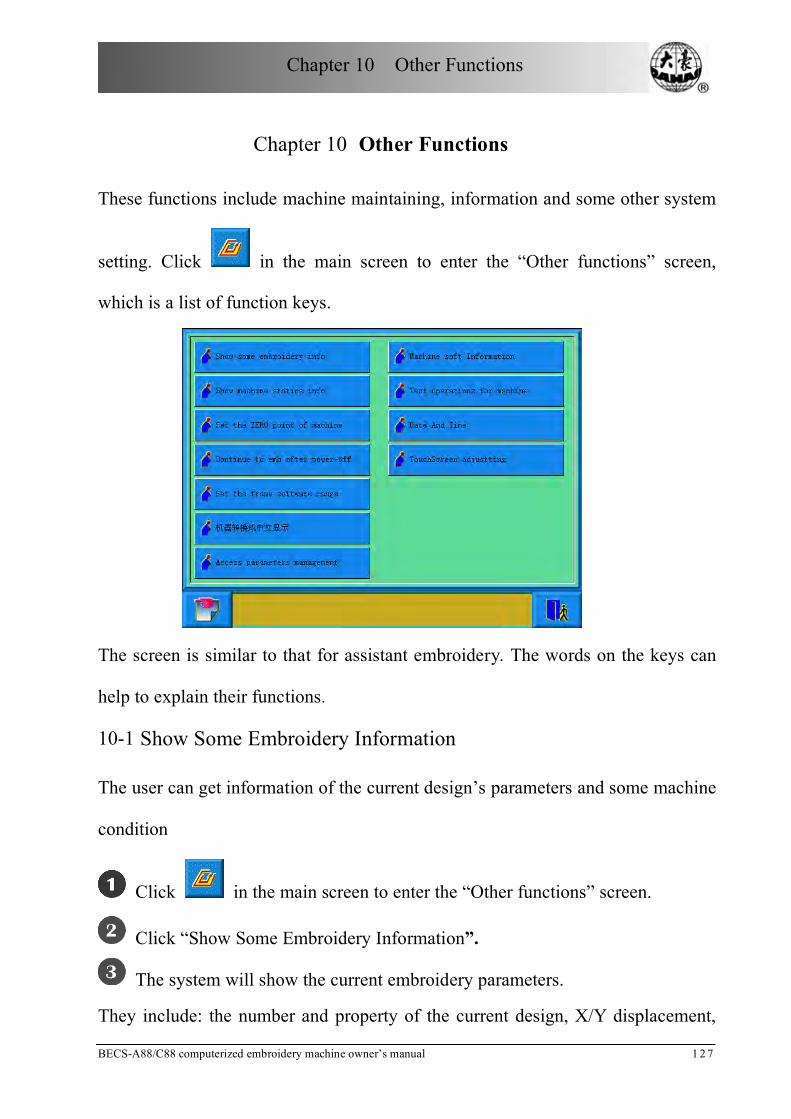
Chapter 10 Other Functions
BECS-A88/C88 computerized embroidery machine owner’s manual 1 2 7
Chapter 10 Other Functions
These functions include machine maintaining, information and some other system
setting. Click in the main screen to enter the “Other functions” screen,
which is a list of function keys.
The screen is similar to that for assistant embroidery. The words on the keys can
help to explain their functions.
10-1 Show Some Embroidery Information
The user can get information of the current design’s parameters and some machine
condition
Click in the main screen to enter the “Other functions” screen.
Click “Show Some Embroidery Information”.
The system will show the current embroidery parameters.
They include: the number and property of the current design, X/Y displacement,
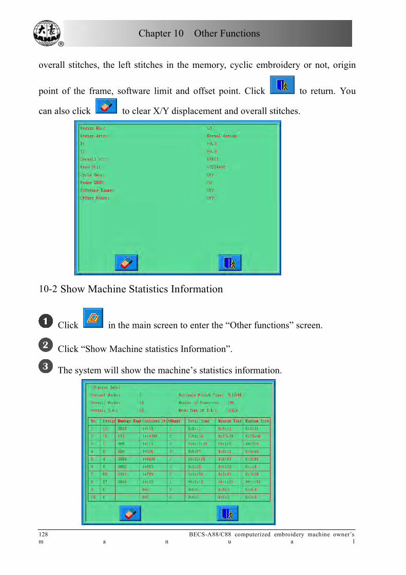
Chapter 10 Other Functions
128 BECS-A88/C88 computerized embroidery machine owner’s m a n u a l
overall stitches, the left stitches in the memory, cyclic embroidery or not, origin
point of the frame, software limit and offset point. Click to return. You
can also click to clear X/Y displacement and overall stitches.
10-2 Show Machine Statistics Information
Click in the main screen to enter the “Other functions” screen.
Click “Show Machine statistics Information”.
The system will show the machine’s statistics information.

Chapter 10 Other Functions
BECS-A88/C88 computerized embroidery machine owner’s manual 1 2 9
In the above screen, the statistics information is displayed in a chart. The user can
click to clear the value and click to return.
10-3 Setting Frame Protection when Power Off (Setting the Machine’s
Zero Point)
Setting the frame origin point is the premise for saving the design’s start point and
setting frame protection when power off. So after machine installation or
maintenance, it’s necessary to set the frame zero point.
Click in the main screen to enter the “Other functions” screen.
Click “Set the zero point of machine”.
Choose between “Manual way” and “Auto way”
Before setting the frame zero point manually, manually move the frame the
desired origin point position, and click the key. Then the system will save the
current frame as the zero point. When meeting emergency stop because of
malfunctions or something unusual such as power off unexpectedly, etc. the
machine will cancel the “setting frame origin” function to avoid the mistakes. So,

Chapter 10 Other Functions
130 BECS-A88/C88 computerized embroidery machine owner’s m a n u a l
at that time, you should do operation of “Setting frame zero point manually” again
at the last frame zero point. If the frame has been moved after power off, or if
power on again after maintenance, you should do again the operation of “Setting
frame zero point manually”.
If you hope the system automatically set the frame origin point, click “Auto way”,
and the system will move the frame automatically and set the zero point according
to the limit switch. So please ensure that the limit switch has been installed into
the machine and it’s effective.
10-4 Frame Restoring after Power Off
In case of frame having been moved after power off, this operation can be used to
restore the frame position before power off when the power is on again. The
proper performance of this operation is based on the “SET POWER
RESUME/ZERO POINT”. In addition, if the power is off in the process of
embroidering operation and the frame has not been shifted, you also can directly
pull the operation bar to continue embroidering after power is on again.
Click in the main screen to enter the “Other functions” screen.
Click “Continue to Emb. after power-off”.
If it is “Setting frame zero point automatically”, the machine will automatically
move to the frame zero point and then back to embroidering position before
power-off. It will be invalid if the operation of “setting frame zero point
manually” is done.

Chapter 10 Other Functions
BECS-A88/C88 computerized embroidery machine owner’s manual 1 3 1
10-5 Set the Frame Software Range
This function is to set the embroidery range set in the software, and limit the
machine embroidering to this range.
Click in the main screen to enter the “Other functions” screen.
Click “Set the Frame Software Range”.
If have already established the software protect, the system hints the
customer to clean original constitution.
After click the confirm key, establish the coordinate of the left- up corner.

Chapter 10 Other Functions
132 BECS-A88/C88 computerized embroidery machine owner’s m a n u a l
Use the move frame key on panel to move the embroidery frame, to confirmed
left-up corner point of soft limit position, click to confirm.
Moving embroidery frame, input coordinate of right-down corner of soft limit
position.
Use the move frame key on panel to move the embroidery frame, to confirmed
right-down corner point of soft limit position, click to confirm.
The system memory embroidery frame software protection
10-6 Chinese/English/Turkish/Spanish Conversion
System supports Chinese English, Turkish and Spanish conversion.
Click the “other functions” key to enter into other functions screen.

Chapter 10 Other Functions
BECS-A88/C88 computerized embroidery machine owner’s manual 1 3 3
Click the shift key to show “中文/English/Turkey” or “中文/English/Espana”.
Click the shift key can view the screen in中文, English, Turkish and Spanish by
turns.
中文

Chapter 10 Other Functions
134 BECS-A88/C88 computerized embroidery machine owner’s m a n u a l
English
Turkish
Spanish
10-7 Machine Management Access
For a convenient machine management, the common user can't access the setting
of all parameters; the roles of the customer are divided into the common user,
machine administrator and factory customer. The purview of the common user is
the lowest, can only modify the embroidery parameter of the machine, machine
administrator can also modify managing parameter, but the factory user can
modify all parameters.
Click the usage purview management key, the system manifestation usage

Chapter 10 Other Functions
BECS-A88/C88 computerized embroidery machine owner’s manual 1 3 5
purview management screen.
If after constitution the password, machine administrator or the factory customer
need modifies the parameter, must relieve the password first, then can change, can
also change the password, conservancy and instauration parameters here.
10.7.1 Machine Administrator relieve/change the password
Machine at a factory be placed in the release lock appearance, also is to say that
the customer can modify all parameters, machine administrator can modify the
password, after modify the password, the common customer can't modify the
machine application parameter. The administrator must to relieve the lock
appearance of the system parameter, also can modify after inputting the password.
Click other function key on the main appearance; enter the other
functions operation screen
Click machine administrator relieve/ change the password key
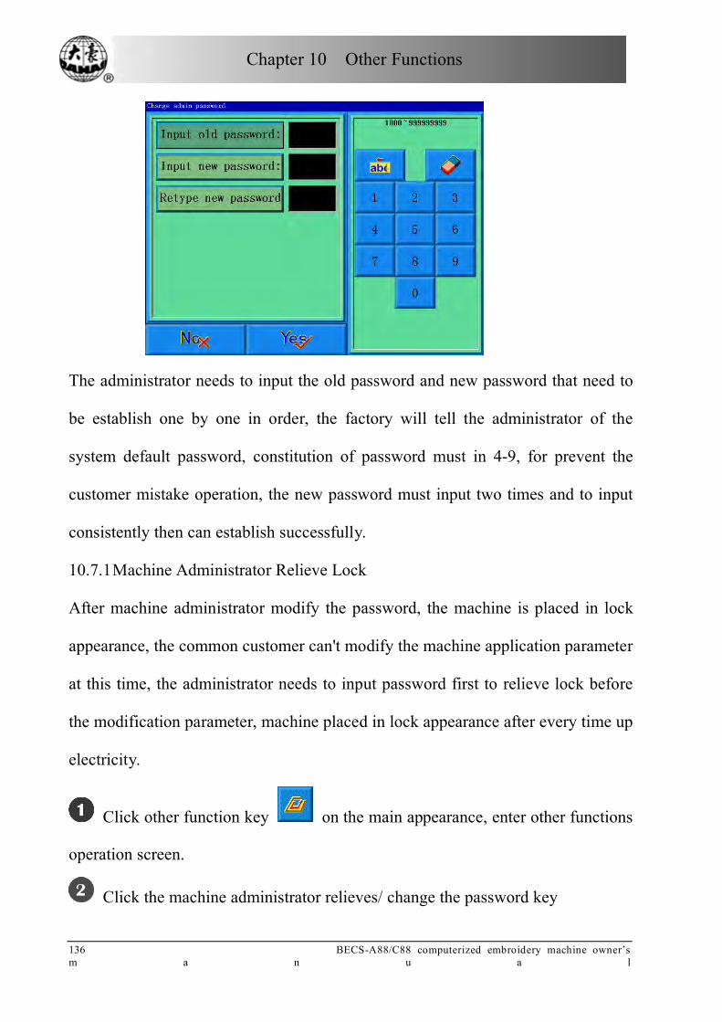
Chapter 10 Other Functions
136 BECS-A88/C88 computerized embroidery machine owner’s m a n u a l
The administrator needs to input the old password and new password that need to
be establish one by one in order, the factory will tell the administrator of the
system default password, constitution of password must in 4-9, for prevent the
customer mistake operation, the new password must input two times and to input
consistently then can establish successfully.
10.7.1 Machine Administrator Relieve Lock
After machine administrator modify the password, the machine is placed in lock
appearance, the common customer can't modify the machine application parameter
at this time, the administrator needs to input password first to relieve lock before
the modification parameter, machine placed in lock appearance after every time up
electricity.
Click other function key on the main appearance, enter other functions
operation screen.
Click the machine administrator relieves/ change the password key

Chapter 10 Other Functions
BECS-A88/C88 computerized embroidery machine owner’s manual 1 3 7
The system manifestation customer inputs the password screen.
The administrator input password
After the administrator input the password, the system is placed in the lock
appearance; the customer can modify the machine application parameter.
10.7.2 The Machine Administrator Saves and Recovers Optimize Parameter
The machine administrator can save and recover the homologous machine
parameter. If the customer hopes to keep the parameter that establish already at
present, as long as click" machine administrator save optimize parameter" key, the
system can keep a set of parameter only, being to keep again the optimize
parameter, will overlay the parameter of the last time conservancy. If the customer
hopes to recover the optimize parameter that saved in last time, as long as click"
machine administrator recover optimize parameter" key, the system will hint the
customer confirmation recovery operation, after customer confirm, the system
will recover the value of parameter that saved into the system.

Chapter 10 Other Functions
138 BECS-A88/C88 computerized embroidery machine owner’s m a n u a l
10.7.3 Factory Customer Change the Password
The factory customer can modify all parameters, before the machine leave factory,
the machine is placed in the appearance of solve the lock. After modify the
password, the machine is placed in lock status, if want to modify the machine
parameter, need to input the password first to make the machine be placed in the
release lock appearance, machine afresh up after give or get an electric and was
placed in the lock appearance again. The concrete process is similar to the process
of administrator release/ change of the process, here no longer give unnecessary
details.
10.7.4 Factory Relieve the Password
The method that the factory relieves the lock is similar to the method that
administrator customer relieves the lock, here no longer give unnecessary details.
10.7.5 The Factory Saves and Recovers Optimize Parameter
The factory customer can save and recover the parameter that was set, the method
is similar with administrator save and recover the parameter, here no longer give
unnecessary details.
10.7.6 The Initialization Parameter of Machine
This function can initialize the general embroidery parameter of the machine. In
the system saved a group of value of default parameter value, the factory and
embroidery factory administrator can save corresponding parameter that they
managed. When use this function to do initialize the parameter, the regularity is as
follows:
Chapter 10 Other Functions
BECS-A88/C88 computerized embroidery machine owner’s manual 1 3 9
When the factory password and embroidery factory administrator password
were not established, then do initialize all of general embroidery parameters to the
default value that was saved by system.
When that factory password has already established and has already decrypt,
and then do initialize all of general embroidery parameters to the default value that
was saved by system.
The factory password has already established and hasn’t decrypt, embroidery
factory administrator password has already established and has already decrypt,
then the machine parameter was managed by factory recover to parameter value
was saved by factory, the other parameters were initialized to default value that
saved by system.
The factory password has already established and hasn’t decrypt, embroidery
factory administrator password has already established and hasn’t decrypt, then
the machine parameter was managed by factory recover to parameter value was
saved by factory, the machine applications parameter was managed by
administrator recover to parameter value that saved by administrator, the other
parameters were initialized to default value that saved by system.
The factory password hasn’t establish, embroidery factory administrator
password has already established and has decrypt, and then do initialize all of
general embroidery parameters to the default value that was saved by system.
The factory password hasn’t establish, embroidery factory administrator
password has already established and hasn’t decrypt, then the machine

Chapter 10 Other Functions
140 BECS-A88/C88 computerized embroidery machine owner’s m a n u a l
applications parameter was managed by administrator recover to parameter value
that saved by administrator, the other parameters were initialized to default value
that saved by system.
10-8 Validation of factory ID
Note : BECS-C88 has this function, but BECS-A88 has not.
The factory ID is saved in the hardware of both control system and display system.
Meanwhile, factory ID are also contained in control system software and display
system software. When power-on, validation procedures run automatically in both
systems to test if factory IDs are matching. After that, system will test if the
factory ID of control system and display system are matching. System works
properly only when validation results are all positive, otherwise it will send out
error notices when machine is electrified. Related errors and their solutions are
listed below:
Error Description Cause Solution FC:01 Operation software and hardware is not consitent!
Operation software and hardware validation of factory ID is not consitent
Change operation system software of certain factory
FC:02 Control software and hardware is not consitent!
Control software and hardware validation of factory ID is not consitent
Change control system software of certain factory
FC:03 Control system and Operation system's factory ID is not match!
Control system and Operation system's factory ID is not match
Change the software & hardware factory IDs of control system or operation system
FC:04 Control system has password!
Control system has password and display system has not password
Relieve control system password or change operation system
FC:05 Operation system has password from C18!
Operation system has been used and password from C18
Change operation system software
FC:06 Operation system communicate error!
Communicate connection error
Affirm connection is ok

Chapter 10 Other Functions
BECS-A88/C88 computerized embroidery machine owner’s manual 1 4 1
Error Description Cause Solution FC:07 Operation system factory ID not match!
Operation system hardware not match
Change Operation system circuit and affirm them match
Note: If machine send out “FC:06” error, the menu on display can be used except
or . And if machine send out other error except “FC:06”,all the menu
on diaplay can not be used.
10-9 The Software Information of the Machine
Click in the main screen, and enter the screen for other functions.
Click
The user can check the software information of upper and lower CPUs. (The upper
is for data and the lower is for control.) And click to return.
10-10 The Adjustment of Machine
This operation to provide to maintenance man to use only, the common

Chapter 10 Other Functions
142 BECS-A88/C88 computerized embroidery machine owner’s m a n u a l
maintenance man not to use, this operation involves some mechanical works, so
the need to notice the human body safety and equipments safeties when use it..
Adjust function to mainly use in the test of the machine, support and check break
down, include as follows function:
The light electricity coder examination
The rotate speed of principal axis examination
Turn to move the principal axis from 100 degrees to the certain angle
Test bar switch
Test limit switch
Test electromagnet of machine head
Test thread-trimming electromagnet/ motor
Test thread-holding electromagnet
Test thread-catching electromagnet/ motor
Test thread break detecting
10-11 Date and Time
In date and time screens, the customer can look into and modify the system for
current date and time.
10-12 The Adjustment of Touch Screen
After use a period of time of touch screen, probably occur the drift of the data,
result in the problem of click the key not accurate, the problem can be resolve
through adjust the touch screen.

Chapter 10 Other Functions
BECS-A88/C88 computerized embroidery machine owner’s manual 1 4 3
Click other function key on main screen, enter other functions
operation screen.
Click touch screen adjust key
Typing in administrator password or factory password
Click the centre of the cross in adjustment screen one by one. If the screen
image shows like following after clicking the centre of the cross, then the touch
screen needs no adjustment; if the screen shows like following after clicking other
part of the screen except the centre of the cross, then the screen needs adjustment.
See detailed the operations in 10.12.
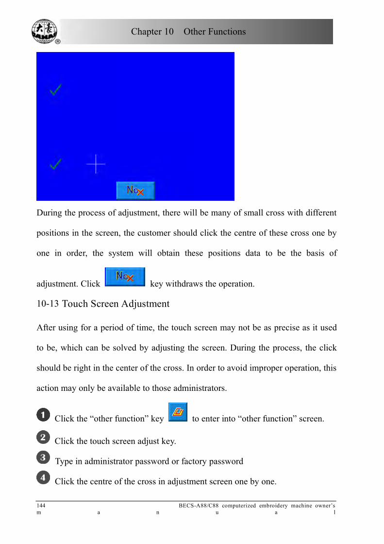
Chapter 10 Other Functions
144 BECS-A88/C88 computerized embroidery machine owner’s m a n u a l
During the process of adjustment, there will be many of small cross with different
positions in the screen, the customer should click the centre of these cross one by
one in order, the system will obtain these positions data to be the basis of
adjustment. Click key withdraws the operation.
10-13 Touch Screen Adjustment
After using for a period of time, the touch screen may not be as precise as it used
to be, which can be solved by adjusting the screen. During the process, the click
should be right in the center of the cross. In order to avoid improper operation, this
action may only be available to those administrators.
Click the “other function” key to enter into “other function” screen.
Click the touch screen adjust key.
Type in administrator password or factory password
Click the centre of the cross in adjustment screen one by one.
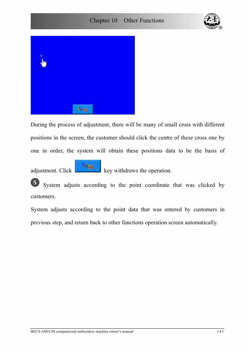
Chapter 10 Other Functions
BECS-A88/C88 computerized embroidery machine owner’s manual 1 4 5
During the process of adjustment, there will be many of small cross with different
positions in the screen, the customer should click the centre of these cross one by
one in order, the system will obtain these positions data to be the basis of
adjustment. Click key withdraws the operation.
System adjusts according to the point coordinate that was clicked by
customers.
System adjusts according to the point data that was entered by customers in
previous step, and return back to other functions operation screen automatically.

Chapter 11 Sequin Embroidery
146 BECS-A88/C88 computerized embroidery machine owner’s m a n u a l
Chapter 11 Sequin Embroidery
11-1 Brief Introduction on Sequin Embroidery
Sequin embroidery is composed by several sequins and threads. We choose those
hard materials with smooth surfaces as the sequins. Embroidery works will be
shining with these sequins attached. Sequin embroidery has its own way of
designing. After design selection, changing and editing, users can pull bar to start
embroidering. Sequin embroidery usually goes with normal or special
embroideries to create combined new designs.
A. Scope:
This system applies to sequin embroidering control system which combines
normal embroidering mechanism and sequin sending mechanism.
B. Features and Functions:
1. Two sending modes: Wheel and Fork;
Wheel: the core part is a wheel-like device in the whole mechanism. Its operating
principle is to wheel continuous towards one direction to send sequins into
position.
Fork: the core part is a planar linkage. Its operating principle is to move
back-and-forth to send the sequins into position.
2. Sequin mending and Independent actions of the two sequin sending mechanism
3. Delivering a sequin by operating either manual sequin sending button or the
control panel
Chapter 11 Sequin Embroidery
BECS-A88/C88 computerized embroidery machine owner’s manual 1 4 7
4. Display working status separately
5. type of sequin sending and angle can be changed by operating on the control
panel.
C. Specifications
1. Sequin diameter range: 3mm to 9mm;
2. The maximum speed for sequin embroidery is 850 rpm.
11-2 Operating Sequin Embroidery
11.2.1 Direction of Sequin Parameters
Parameters of sequin embroidery are listed in appendix one. Here we explain some
of them as following.
1. Machine Parameters
(1) The left (right) sequin device: usually, sequin device is located in either first
needle position or the last (double sequin embroidery machine has sequin
devices on both the first and the last needle position). Users can set “Yes” or
“No”, which will activate or inactivate the particular sequin device.
(2) The acting angle of left (right) sequin device should be adjusted depending on
real status. Usually this parameter has been set during the manufacture
progress.
(3) Sequin sending angle of left (right) sequin device: it can be changed by
making adjustment to the angle of main shaft motor.
(4) Time needed for the sequin device’s going down: this parameter indicates the
time between device’s going down and the start of embroidering(0-15,default

Chapter 11 Sequin Embroidery
148 BECS-A88/C88 computerized embroidery machine owner’s m a n u a l
value is 3). We recommend that valve controlled sequin sending mechanism
uses the default value, while motor controlled ones use 4 to 5.
2. Practical Parameters of the Machine
(1) The speed limit of left (right) sequin device:
The speed limit depends on the sequin size. However, sewing the same sequin
with different mechanical structure, the acting angle could be different, which is
directly related to the maximum speed.
Note: the maximum speed of normal embroidery should be higher than the speed
limit of sequin embroidery.
(2) Automatic start or not:
When the setting is “Yes”, system will start embroidering sequin automatically.
When the setting is “No”, embroidery needs manually start.
(3) Sequin device automatically lift up in case of thread break
When the setting is “Yes”, system will lift up automatically in case of thread
break.
When the setting is “No”, the sequin device needs manually lifting the presser
foot.
11.2.2 Steps of Setting Sequin Parameters
See 5.1 General Setting of Parameters for Sequin Embroidery
11.2.3 Manual Operation of Sequin Embroidery
It has two ways of operation, centralized operation and separated operation.
1. Centralized Operation

Chapter 11 Sequin Embroidery
BECS-A88/C88 computerized embroidery machine owner’s manual 1 4 9
Centralized operation can be divided into three parts: “sequin start”, “sequin
finish” and “sequin sending”.
(1) Press the key in the bottom of the screen,
select , and then select “sequin start”, then
all the presser feet go down.
(2) Press the key in the bottom of the screen,
select , and then select “sequin finish”,
then all the presser feet go up.
(3) Press the key in the bottom of the screen,
select , and then select “sequin sending”,
then all the devices will send out one sequin at the time you press the key
(presser foot should be down at first).
2. Separated Operation
Separated sequin sending manually: switch down the sequin control switch to send
sequin manually to the separate head. Users can press the switch to let the device
send one sequin at a time. You keep on pressing the switch, sequins will be
continuously sent out.
Status lamps will tell users about the head conditions, which offer easy debugging
and trouble shooting.
a) When the sequin control switch is turned up, blue light is out and the valve
is up. No operation is acceptable.
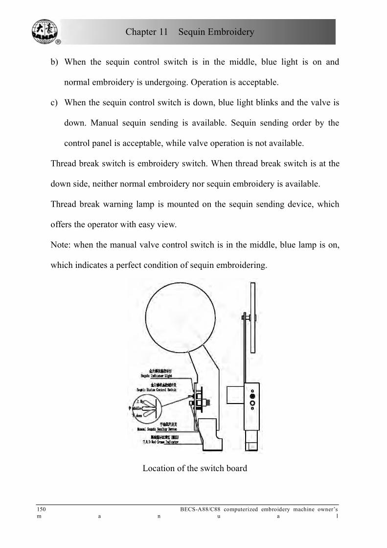
Chapter 11 Sequin Embroidery
150 BECS-A88/C88 computerized embroidery machine owner’s m a n u a l
b) When the sequin control switch is in the middle, blue light is on and
normal embroidery is undergoing. Operation is acceptable.
c) When the sequin control switch is down, blue light blinks and the valve is
down. Manual sequin sending is available. Sequin sending order by the
control panel is acceptable, while valve operation is not available.
Thread break switch is embroidery switch. When thread break switch is at the
down side, neither normal embroidery nor sequin embroidery is available.
Thread break warning lamp is mounted on the sequin sending device, which
offers the operator with easy view.
Note: when the manual valve control switch is in the middle, blue lamp is on,
which indicates a perfect condition of sequin embroidering.
Location of the switch board

Chapter 11 Sequin Embroidery
BECS-A88/C88 computerized embroidery machine owner’s manual 1 5 1
11.2.4 Sequin Mending
After thread break or manually turning on the red lamp, pull bar and the
machine is in sequin mending. All the sequin devices will lift up; machine
stops when it backs to the stop embroidering point. Pull bar again to let the
sequin device (on mending head) down for mending. When it reaches the stop
point, machine stops, then other sequin devices will be down to continue
normal embroidery. Mending stitches in machine parameter setting is
ineffective in sequin mending.
11-3 How to Act Sequin Embroidery
Users should take the following steps:
1. Use sequin design. Design selection, changing and editing are required.
2. Set sequin parameters according to the above directions.
3. Check and adjust the sequin sending device to make sure it works
normally.
4. Change the needle position to the sequin position. Make sure the sequin
control switch is in the middle and the blue lamp is on.
5. Pull bar to start embroidering.
11-4 Notice
During the process of embroidering, try to avoid touching the valve control
switch, or it may result in destroy of the sequin sending device.

Chapter 12 Directions on Coiling, Taping and ZIG Embroidery
152 BECS-A88/C88 computerized embroidery machine owner’s m a n u a l
Chapter 12 Directions on Coiling, Taping and ZIG Embroidery
Note: A88 system has not this function and operations.
12-1 Function Introductions
1. Coiling function: This is a method to wind coiling thread(s) at an equal
interval around a core thread in a form of coil. Left Coiling (clockwise) and Right
Coiling (counterclockwise) are both available in coiling function, which could be
opted in computer parameters.
2. Taping function: Tape can be used as embroidery material. It includes
taping 1and taping 2 (blind embroidery)
3. ZIG function: ZIG sewing lever swings to the right or left per stitch in
regard to the direction of original stitches. The upper thread forms ZIG on the
embroidered material. There are six special stitches: Z1, Z2, Z3, Z4, Z5 and Z6.
Their stitches are as follows.
Z1 Z2 Z3 Z4 Z5 Z6
For convenience, Coiling, Taping and ZIG-sewing are all called special
embroidery in the following.
4. Standard embroidery head and special embroidery head can be switched
automatically or manually.
5. Coiling, Taping and ZIG functions can be switched at will.

Chapter 12 Directions on Coiling, Taping and ZIG Embroidery
BECS-A88/C88 computerized embroidery machine owner’s manual 1 5 3
6. The nipple of Special embroidery can be raised and lowered
automatically or manually. (Only for the machines installed with relevant
apparatus)
7. The highest speeds of Standard embroidery head and special embroidery
head can be set up respectively.
8. Auto saving of the stop-embroidery point of the M axis:The embroidery
work can continue from the stop-embroidery point when the power recovers.
9. The trimming function of the special embroidery head (no
trimming\trimming of the bottom thread\trimming of both the upper and bottom
threads)
10. The nipple of Special embroidery can be raised and lowered automatically
before manual frame shifting or embroidering.
11. ZIG sewing lever can be tested manually.
12-2 Main Technical Details
1. The sequence of needle positions on Standard embroidery head and
special embroidery head: This control system default that the first one is special
embroidery needle position and Standard embroidery’s are from second to end.
2. Speed range of Special Embroidery: 300—600rpm, minimum of stepping
precision is 10r.
3. Angle of M-axis rotated manually: 18°/step.

Chapter 12 Directions on Coiling, Taping and ZIG Embroidery
154 BECS-A88/C88 computerized embroidery machine owner’s m a n u a l
12-3 Parameters and parameter setting
Press the parameter-setting key in the main screen to set relative
parameters for special embroidery. These parameters are listed in the
following directions: embroidery parameter 2, machine application 4 and 5,
machine parameter 3, 4 and 5.
Press embroidery parameter 2, the following parameters can be set:
1. B16 Clamp Foot Min Height Adj : 0~255
This parameter is in charge of the lowest point of the presser foot during operation.
Press the button and set parameter on the right side of the screen. Input the
required value by pressing digital keys. Press the key to cancel a digit and
to cancel all the digits. After input, press the key to finish setting.
The following parameters can be set in direction of Machine application 4:
2. C35 Speed for Sequin L.: 300~600
Press this key in parameter setting screen. Press the key or in the right
side of the screen for adjustment, and then press to confirm.
3. C51 Spec Mininum Speed:250~400
The parameter value is the lowest speed that the M axis can be decelerated to.
4. C52 Spec. Speed-Down Angle: 1~180
When the M axis rotating angle is larger than the set value, the main axis begins to
decelerate. The recommended value is 30. Press the key to cancel a digit
and to cancel all the digits. After input, press the key to finish
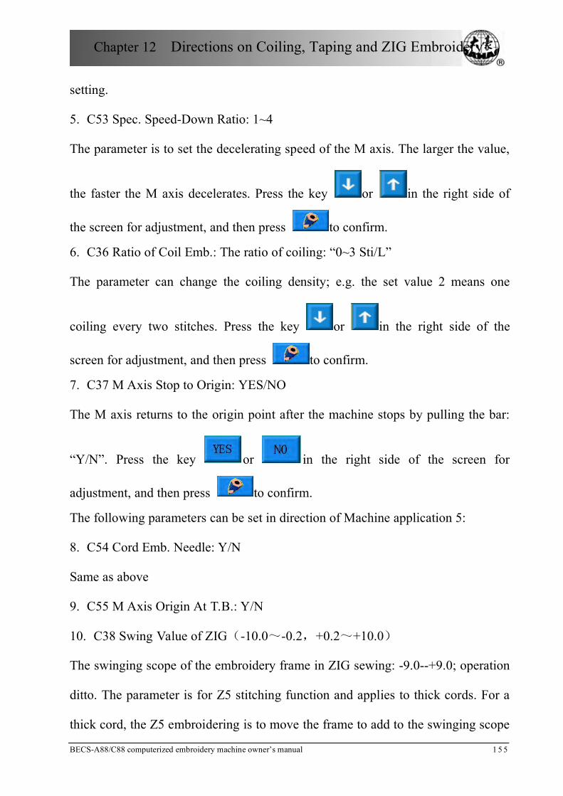
Chapter 12 Directions on Coiling, Taping and ZIG Embroidery
BECS-A88/C88 computerized embroidery machine owner’s manual 1 5 5
setting.
5. C53 Spec. Speed-Down Ratio: 1~4
The parameter is to set the decelerating speed of the M axis. The larger the value,
the faster the M axis decelerates. Press the key or in the right side of
the screen for adjustment, and then press to confirm.
6. C36 Ratio of Coil Emb.: The ratio of coiling: “0~3 Sti/L”
The parameter can change the coiling density; e.g. the set value 2 means one
coiling every two stitches. Press the key or in the right side of the
screen for adjustment, and then press to confirm.
7. C37 M Axis Stop to Origin: YES/NO
The M axis returns to the origin point after the machine stops by pulling the bar:
“Y/N”. Press the key or in the right side of the screen for
adjustment, and then press to confirm.
The following parameters can be set in direction of Machine application 5:
8. C54 Cord Emb. Needle: Y/N
Same as above
9. C55 M Axis Origin At T.B.: Y/N
10. C38 Swing Value of ZIG(-10.0~-0.2,+0.2~+10.0)
The swinging scope of the embroidery frame in ZIG sewing: -9.0--+9.0; operation
ditto. The parameter is for Z5 stitching function and applies to thick cords. For a
thick cord, the Z5 embroidering is to move the frame to add to the swinging scope
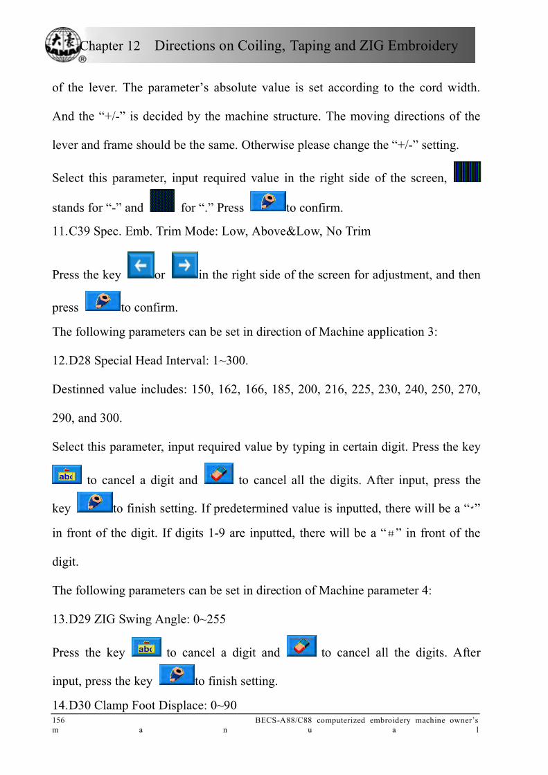
Chapter 12 Directions on Coiling, Taping and ZIG Embroidery
156 BECS-A88/C88 computerized embroidery machine owner’s m a n u a l
of the lever. The parameter’s absolute value is set according to the cord width.
And the “+/-” is decided by the machine structure. The moving directions of the
lever and frame should be the same. Otherwise please change the “+/-” setting.
Select this parameter, input required value in the right side of the screen,
stands for “-” and for “.” Press to confirm.
11. C39 Spec. Emb. Trim Mode: Low, Above&Low, No Trim
Press the key or in the right side of the screen for adjustment, and then
press to confirm.
The following parameters can be set in direction of Machine application 3:
12. D28 Special Head Interval: 1~300.
Destinned value includes: 150, 162, 166, 185, 200, 216, 225, 230, 240, 250, 270,
290, and 300.
Select this parameter, input required value by typing in certain digit. Press the key
to cancel a digit and to cancel all the digits. After input, press the
key to finish setting. If predetermined value is inputted, there will be a “*”
in front of the digit. If digits 1-9 are inputted, there will be a “#” in front of the
digit.
The following parameters can be set in direction of Machine parameter 4:
13. D29 ZIG Swing Angle: 0~255
Press the key to cancel a digit and to cancel all the digits. After
input, press the key to finish setting.
14. D30 Clamp Foot Displace: 0~90
Chapter 12 Directions on Coiling, Taping and ZIG Embroidery
BECS-A88/C88 computerized embroidery machine owner’s manual 1 5 7
Adjusting the working position of clamp foot: “0--90”; operation ditto. The height
is for every stitch. Press the key to cancel a digit and to cancel all
the digits. After input, press the key to finish setting.
15. D50 Z Emb Swing Adj: 0~5
Same as above
16. D31 Rod Pos. of ZIG: Left/ Right
The “ROD POS. OF ZIG” indicates that the position of swing when M axis is in
origin. Setting of this parameter must be kept in line with mechanical position.
Press the key or in the right side of the screen for adjustment, and then
press to confirm.
17. D39 Z Shift Control Angle: 0~180
When the rotating angle is larger than the set value, the Z axis will wing faster.
Press the key to cancel a digit and to cancel all the digits. After
input, press the key to finish setting.
18. D40 Adj Clamp Foot Limit: 0~250
The set value is added to the limit height of the clamp foot. Operation is same as
above.
19. D41 Adj Zig Rod Angle: 1~3
It is the starting angle of the rod, which indicates the relative position of the needle
bar and thread. “1” means the swing starts at an early angle; “2” means the swing
postpones certain angle; “3” indicates the swing postpones certain angle again to

Chapter 12 Directions on Coiling, Taping and ZIG Embroidery
158 BECS-A88/C88 computerized embroidery machine owner’s m a n u a l
start. Press the key or in the right side of the screen for adjustment, and
then press to confirm.
20. D42 Rotary Gap of M Axis: 0~10
The M axis of special embroidery head has mill clearance. So without
compensation, the needle will not fall in the right position. Adjust this parameter
value to ensure that the needle falls in the center of tape.
During machine debugging, parameter value should be “0” when needle falls in
the center of tape. If not, repeat the adjustment to realize the best effect.
Parameter operation is same as above.
Generally, this parameter is managed by professional experts before leaving
factory.
21. D44 M Axis Work OFF Angle: 0, 90
In case of normal and sequin embroidery, the M axis stops at the angle of the set
value. When the distance between the normal embroidery head and special
embroidery head is small, this parameter must be set as 90° to avoid bumping.
The following parameters can be set in direction of Machine parameter 5:
22. D47 Slow Down When Coil Emb: Y/N
Press the key or in the right side of the screen for adjustment, and
then press to confirm.

Chapter 12 Directions on Coiling, Taping and ZIG Embroidery
BECS-A88/C88 computerized embroidery machine owner’s manual 1 5 9
12-4 Relative Operations of Special Embroidery
12.4.1 Shift between Lock Stitch Head and Special Head
1. Manual Shift
In the main screen, press the key to enter into color changing screen.
“1” is for special embroidery, others are for non-special embroideries. Press
certain key to change embroidering pattern. Press to exit. The key
indicates the embroidering pattern, press the key to change other special
embroideries. Press to exit.
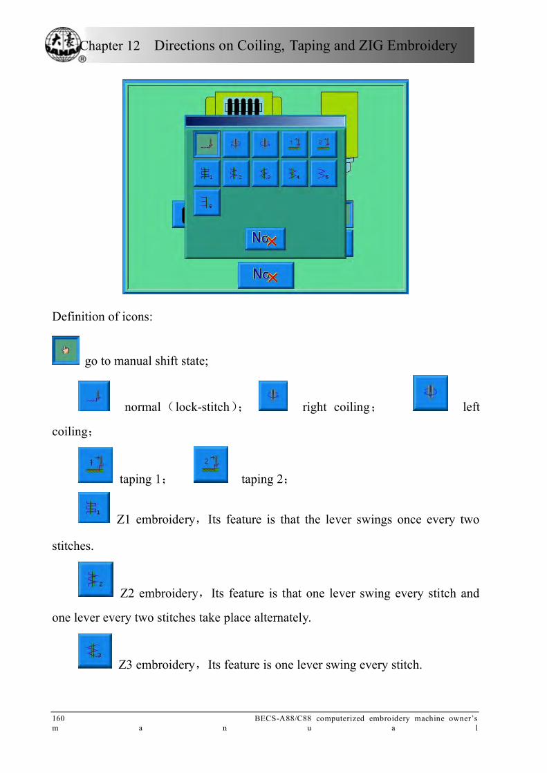
Chapter 12 Directions on Coiling, Taping and ZIG Embroidery
160 BECS-A88/C88 computerized embroidery machine owner’s m a n u a l
Definition of icons:
go to manual shift state;
normal(lock-stitch); right coiling; left
coiling;
taping 1; taping 2;
Z1 embroidery,Its feature is that the lever swings once every two
stitches.
Z2 embroidery,Its feature is that one lever swing every stitch and
one lever every two stitches take place alternately.
Z3 embroidery,Its feature is one lever swing every stitch.

Chapter 12 Directions on Coiling, Taping and ZIG Embroidery
BECS-A88/C88 computerized embroidery machine owner’s manual 1 6 1
Z4 embroidery,Its feature is one lever swing every stitch and its lever
swing direction is opposite to the one of Z3.
Z5 embroidery,Its feature is the same as Z4 and it’s desirable for the
embroidering of thick cords. (Refer to the parameter: the swinging scope of the
embroidery frame in ZIG sewing)
Z6 embroidery,Its feature is three stitches at the same point and one
lever swing every stitch.
2. Automatic Shift
Before embroidering, automatic shift can be achieved through setting the color
changing position.
In the main screen, press the key , and then select to enter into color
changing screen, and then press the key (special head) to change special
embroidery pattern:
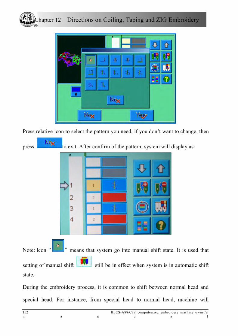
Chapter 12 Directions on Coiling, Taping and ZIG Embroidery
162 BECS-A88/C88 computerized embroidery machine owner’s m a n u a l
Press relative icon to select the pattern you need, if you don’t want to change, then
press to exit. After confirm of the pattern, system will display as:
Note: Icon“ ”means that system go into manual shift state. It is used that
setting of manual shift still be in effect when system is in automatic shift
state.
During the embroidery process, it is common to shift between normal head and
special head. For instance, from special head to normal head, machine will

Chapter 12 Directions on Coiling, Taping and ZIG Embroidery
BECS-A88/C88 computerized embroidery machine owner’s manual 1 6 3
automatically stop at the finishing point; meanwhile, system will give the
following dialogue window. After tape operations are completed, users can pull
bar to close the window and shift the machine back to normal head to proceed
normal embroidering.
From lock-stitch to special embroidering, after automatically shift to “1” (special
head), machine will stop automatically, after the operation on the tape is
completed, pull bar to proceed.
12.4.2 M Axis Operation of Taping Embroidery
This function is only for machines with taping embroidery function and includes
“M axis to be ready”, “M axis to cycle” and “M axis to turn”. In the main screen,
click to enter into the “Assistant Operation” screen, select
to show the special embroidery window, “M
axis to be ready”, “M axis to cycle” and “M axis to turn”.

Chapter 12 Directions on Coiling, Taping and ZIG Embroidery
164 BECS-A88/C88 computerized embroidery machine owner’s m a n u a l
1. Return the M-axis to the Working Point
Press the key and click on the
dialogue window to let the M axis back to the working point, click to
exit.
2. Return the M-axis to the Origin Point
Press the key and click on the dialogue
window to let the M axis rotate to the “zero point”, click to exit.
3. M-axis rotated manually
Press the key and click on the dialogue
window to let the M axis rotate to the left. It will rotate 18° left once you click the
button. After 20 times click, it will return to its origin; while click on
the dialogue window to let the M axis rotate to the right. It will rotate 18° right
once you click the button. After 20 times click, it will return to its origin; click
to exit.
12.4.3 Operations of Clamp Foot
In the main screen, click to enter into the “Assistant Operation” screen, select
to show the special embroidery operation screen.
Press the key and select to lift the
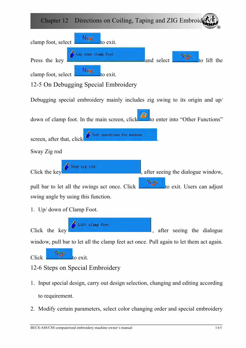
Chapter 12 Directions on Coiling, Taping and ZIG Embroidery
BECS-A88/C88 computerized embroidery machine owner’s manual 1 6 5
clamp foot, select to exit.
Press the key and select to lift the
clamp foot, select to exit.
12-5 On Debugging Special Embroidery
Debugging special embroidery mainly includes zig swing to its origin and up/
down of clamp foot. In the main screen, click to enter into “Other Functions”
screen, after that, click .
Sway Zig rod
Click the key , after seeing the dialogue window,
pull bar to let all the swings act once. Click to exit. Users can adjust
swing angle by using this function.
1. Up/ down of Clamp Foot.
Click the key , after seeing the dialogue
window, pull bar to let all the clamp feet act once. Pull again to let them act again.
Click to exit.
12-6 Steps on Special Embroidery
1. Input special design, carry out design selection, changing and editing according
to requirement.
2. Modify certain parameters, select color changing order and special embroidery

Chapter 12 Directions on Coiling, Taping and ZIG Embroidery
166 BECS-A88/C88 computerized embroidery machine owner’s m a n u a l
pattern.
3. Check special heads to make sure they are in perfect condition.
4. Pull bar to start embroidering.
12-7 Mechanical Category and Driving Mode Choice of Special
Embroidery Machines
Taping machines have three moving parts in the sense of mechanics. We define
them as M axis, E axis and clamp foot axis. M axis rotates a certain degrees every
stitch to trace the stitch, which ensures cords or tapes always in front of needle
movement. E axis swings once every one or two stitch to make the ZIG
embroidery. Clamp foot axis is for lifting and lowering the clamp foot.
1. M axis
The mechanism of M axis can be divided to two types. One is with clutch
device, whose action is controlled by electropneumatic valve or by hand. Its
advantage is that only the M axis of the mending embroidery is moving and
non-mending embroidery heads are still when mending. This will help raise the
quality and efficiency of mending. The other type is without clutch device. Both of
the two types are driven by servomotor and the origin of the M axis is positioned
by proximity switch.
2. E axis
According to the difference in motor and whether to use the proximity switch
for positioning, E axis can be divided to the following types:
1) Stepping motor, driving heads separately, without proximity switch for
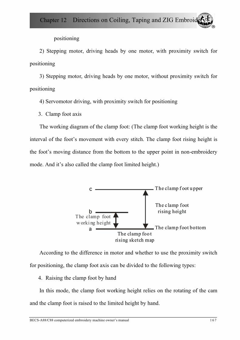
Chapter 12 Directions on Coiling, Taping and ZIG Embroidery
BECS-A88/C88 computerized embroidery machine owner’s manual 1 6 7
positioning
2) Stepping motor, driving heads by one motor, with proximity switch for
positioning
3) Stepping motor, driving heads by one motor, without proximity switch for
positioning
4) Servomotor driving, with proximity switch for positioning
3. Clamp foot axis
The working diagram of the clamp foot: (The clamp foot working height is the
interval of the foot’s movement with every stitch. The clamp foot rising height is
the foot’s moving distance from the bottom to the upper point in non-embroidery
mode. And it’s also called the clamp foot limited height.)
The clamp foot
w orki ng height
The c lamp foot
rising height
The clamp f oot u pper
The clamp foot bottom
The clamp foo t
rising sketch map
a
b
c
The c lamp foot
rising height
The clamp f oot u pper
The clamp foot bottom
The clamp foo t
rising sketch map
a
b
c
According to the difference in motor and whether to use the proximity switch
for positioning, the clamp foot axis can be divided to the following types:
4. Raising the clamp foot by hand
In this mode, the clamp foot working height relies on the rotating of the cam
and the clamp foot is raised to the limited height by hand.
Chapter 12 Directions on Coiling, Taping and ZIG Embroidery
168 BECS-A88/C88 computerized embroidery machine owner’s m a n u a l
(1) 2-phase stepping motor, separately driving the embroidery heads, without
the holding force and proximity switch
It uses a 2-phase stepping motor for driving every special embroidery head
and controlling its working height and limited height. The power is off and there is
no the holding force when the clamp foot stays at the upper point or bottom point.
No proximity switch is taken for positioning. And the controller by default takes
that the foot is at the bottom position when turning on the machine.
(2) 2-phase stepping motor, separately driving the embroidery heads, with the
holding force and without proximity switch
It uses a 2-phase stepping motor for driving every special embroidery head
and controlling its working height and limited height. The power is on and there is
the holding force when the clamp foot stays at the upper point, but not at the
bottom point. No proximity switch is taken for positioning. And the controller by
default takes that the foot is at the bottom position when turning on the machine.
5. Mono-phase AC motor, driving the embroidery heads by one motor, 2
proximity switches
In this mode, the clamp foot working height relies on the rotating of the cam
and the clamp foot is raised to the limited height by one mono-phase AC motor
driving the clamp axis. Both the upper and bottom points are set with a proximity
switch to adjust the clamp foot rising height. Neither the upper nor bottom point
has the holding force.
6. (2-phase or 3-phase) stepping motor, driving the embroidery heads by one

Chapter 12 Directions on Coiling, Taping and ZIG Embroidery
BECS-A88/C88 computerized embroidery machine owner’s manual 1 6 9
motor, 1 proximity switch
In this mode, the clamp foot working height relies on the rotating of the cam
and the clamp foot is raised to the limited height by stepping motor driving the
clamp axis. The upper point is set with a proximity switch to position. The bottom
point is set by parameters. Both the upper and bottom points have the holding
force.
7. Pneumatic motor, separately driving the embroidery heads, without
proximity switch.
In this mode, the clamp foot working height relies on the rotating of the cam
and the clamp foot is raised to the limited height by pneumatic motor driving the
heads separately.
8. The composition chart for special embroidery machine controller
For different control systems, the E854 board takes different software programs
while the E874 board changes the DIP switches. Refer to 12-8.
12-8 Definition Charts of DIP Switches of E874 Boards Chart 1:
DIP1 Composition Description of the M axis
OFF Manual clutch or without any clutch
ON Automatic clutch
Chart 2:
DIP2 DIP3 Composition Description of the E axis
ON ON Stepping motor, without proximity switch for positioning
ON OFF Stepping motor, with proximity switch for positioning
OFF ON Servomotor driving, with proximity switch for
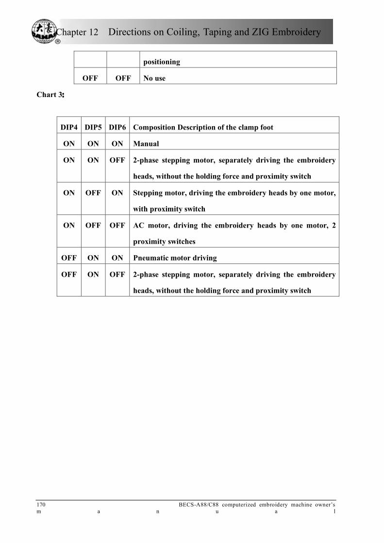
Chapter 12 Directions on Coiling, Taping and ZIG Embroidery
170 BECS-A88/C88 computerized embroidery machine owner’s m a n u a l
positioning
OFF OFF No use
Chart 3:
DIP4 DIP5 DIP6 Composition Description of the clamp foot
ON ON ON Manual
ON ON OFF 2-phase stepping motor, separately driving the embroidery
heads, without the holding force and proximity switch
ON OFF ON Stepping motor, driving the embroidery heads by one motor,
with proximity switch
ON OFF OFF AC motor, driving the embroidery heads by one motor, 2
proximity switches
OFF ON ON Pneumatic motor driving
OFF ON OFF 2-phase stepping motor, separately driving the embroidery
heads, without the holding force and proximity switch

Appendix Ⅰ Parameter Setting List
BECS-A88/C88 computerized embroidery machine owner’s manual 1 7 1
Appendix Ⅰ Parameter Setting List
**“Sti.” For stitches; “Emb.” For embroidery; “T. B.” for thread break; “N”
for the needle number of machine heads
Number Name Recommended Value
Range of Setting Note
Frequently-Used Parameters A01 X&Y Scales 100/100 50%~200% Scales of the design in
X and Y directions A02 Rotate 0 0~89 Rotating angle of the
design A03 Direction P A04 Prior Mode Rotate Rotate, scale A05 Rep. Mode Normal Normal, part Not used A06 Rep. Prior X Prior X prior, Y prior A07 X&Y Reps 1/1 1~99 A08 X&Y Interval 0.0/0.0 -999.9~+999.9
Emb. Parameters B01 Auto Origin Yes No, Yes B02 To Do Cyclic
Emb. No No, Yes Whether to
automatically repeat embroidering the design It often accompanies repetition or special punched design.
B03 Overframe by Step
No No, Yes
B04 Display Sti-Num or Not
Yes No, Yes
B05 T. B. Detect Yes No, Yes Thread break detect
B06 Stop after T. B. Detect
Yes No, Yes
B07 Press key after T. B.
No No, Yes Press key (pull bar) after T. B.
B08 T. B. Back Sti. 0 0~7 It is unavailable to some machine types.
B09 Patch Count 1 1~10 How many stitches to patch before the thread break point
B10 Speed Down Stop No Change, Down, Stop

Appendix Ⅰ Parameter Setting List
172 BECS-A88/C88 computerized embroidery machine owner’s m a n u a l
Number Name Recommended Value
Range of Setting Note
After Patch B11 Sti. Not T.B.
Detect 0~15
B12 T. B. Detect When Jump
No No, Yes
B13 Start for Same Colors
Yes No, Yes Whether to start in color-changing way when the later needle position is same to the former one
B14 To Set All Heads Patch
No No, Yes If “Yes”, all unclosed heads do patching when patching.
B15 Emb Show BackGround
Yes No, Yes
B16 Clamp Foot Min Height Adj
1 0~255 A88 machine has not it
B17 Up Value When Jump&Nocut
Yes No, Yes The same as above
Machine Applications C01 Jump & Trim 3 Jump No Trim, 1Jump~7Jump C02 Sewing Empty
Stitch No No, Yes If “Yes”, the machine
will omit the empty stitches (needle moving without embroidering). If “No”, the empty stitches won’t be omitted.
C03 Stop to Color No No, Yes Change stop codes into color-changing codes. It’s specialized for some countries/regions.
C04 Store Manual Color
No No, Yes If “Yes”, manual color-changing is stored in the color-changing order. After embroidery, the setting will automatically change into “No”.
C05 Value for Thick Cloth
0 0~3
C06 Frame Curve & F6/230 F1/230,240,250,260,270 F2 and F4 are frame

Appendix Ⅰ Parameter Setting List
BECS-A88/C88 computerized embroidery machine owner’s manual 1 7 3
Number Name Recommended Value
Range of Setting Note
Angle F2/230,240,250,260,270 F3/230,240,250,260,270, 280,290 F4/230,240,250,260,270, 280,290 F5/230,240,250,260,270, 280,290 F6/230,240,250,260,270 280,290
curve. The later values are the angles of frame starting.
C07 Max. Speed 700-850 250,300,350,⋯,1000
C08 Shift Stitch
Length(mm)
5.0 1.0~10.0 When the stitch length is longer than the set value, the machine will lower the speed.
C09 Minimum Speed
400 250,300,350,…,600
C10 Jump Stitch Speed
400-750 400,410,750 Set the rotation speed for jump stitch.
C11 Stitches After Trim
2 1~7
C12 Startup Stitches 1 1~9 Set the startup stitch number.
C13 Set Run Speed 80 80,90,…,150 C14 Speed of Slow
Emb. 400
80 (rpm)、the value of the
minimum speed
C15 High Frame-Shift Speed
16 0,1,2,…,30
C16 Low Frame-Shift Speed
12 0,1,2,…,30
C17 Turn Off Trimming
No No, Yes
C18 Length of Trim 1 1~8 1 is the minimum length and 8 is the maximum length.
C19 Lock Num. After Trim
2 0~3 Set the lock stitch number when pulling the bar for embroidery after setting the trimming.
C20 Lock Stitch. Yes No, Yes

Appendix Ⅰ Parameter Setting List
174 BECS-A88/C88 computerized embroidery machine owner’s m a n u a l
Number Name Recommended Value
Range of Setting Note
When Trim C21 Length of Lock
Sti.(mm)
0.6 0.3~1.5
C22 Frame after Trim
No No, Yes
C23 Action after Trim
Frame Y Frame X, Frame Y, Move Needle
C24 Main Motor Para.
1 0~30 The parameter is invalid when it’s a servo motor. When it’s an electromagnetic motor, increase this parameter value to avoid main shaft vibration during braking. Usually it’s set as 1.
C25 Set Break Para. 0 0~30 When the main shaft motor is an electromagnetic motor, the value is usually set as 9. When it is a servo motor, the parameter is usually set as 5—7.
C26 Para. Of Needle Down
15 0~30
C27 Detect T. B. Mode
1 1,2
Mode 1 uses the common take-up spring. Mode 2 uses the chopping wheel.
C28 STI. For Filter T.B.
3 1~6
C29 Needle of Boring
No, 1, N
C30 Boring Emb. Disp.
0 0mm,12mm
C31 Speed for Sequin R
400 300,310,⋯,the maximum
speed
C32 Speed for Sequin L
400 300,310,⋯, the maximum
speed

Appendix Ⅰ Parameter Setting List
BECS-A88/C88 computerized embroidery machine owner’s manual 1 7 5
Number Name Recommended Value
Range of Setting Note
C33 Auto Start for Sequin
No No, Yes
C34 Sequin Off after T.B.
No No, Yes
C35 Speed for Sequin L
400 300~600 A88 machine has not it
C51 Spec Mininum Speed
250 250~400 The same as above
C52 Spec. Speed-Down Angle
30 1~180 The same as above
C53 Spec. Speed-Down Ratio
2 1~4 The same as above
C36 Ratio of Coil Emb.
0 Sti/L 0~3 Sti/L The same as above
C37 M Axis Stop to Origin
Yes No, Yes The same as above
C54 Cord Emb. Needle
Yes No, Yes The same as above
C55 M Axis Origin At T.B.
Yes No, Yes The same as above
C38 Swing Value of ZIG
0.2 -10.0~ -0.2,+0.2~+10 The same as above
C39 Spec. Emb. Trim Mode
Low Low, Above&Low, No Trim The same as above
C40 No Output Design
No No, Yes It’s possible to change the value after setting the administrator password and inputting the right password.
C41 Server Port C42 MAC Address C43 IP Address C44 Server IP C51 Sequin Ind.
UpDown Yes No, Yes A88 machine has not it
Machine Paramaters D01 Needles 1,2,…,MAXNEEDLE Set the value according
to the machine situation. E.g. the value should be 9 for 9

Appendix Ⅰ Parameter Setting List
176 BECS-A88/C88 computerized embroidery machine owner’s m a n u a l
Number Name Recommended Value
Range of Setting Note
needle machine. If the value is different from the machine needles, the color-changing will be abnormal.
D02 Startup Acce. 12 1,2,3,…,30 Increase the value to bring a quicker speedup after pulling the bar.
D03 Set Hold Startup Para.
0 0~3
D04 Speed after Trim
80 60,70,80,…,150 The parameter sets the rotation speed for lock stitch.
D05 Speed When Trimming
80 80,90,100,…,250
D06 Spin Rounds for Brake
1 1,2 2 for most machines, 1 for miniature type and machines with servo control main shaft motor.
D07 Check Trim is OK
No No, Yes
D08 Hook Angle by Motor
0 -100~+100 Set the hook angle by motor. When the value is increase, the hook angle is moved backward.
D09 Hook Ratio by Motor
2 1:9,1:10,1:12,1:15,1:18,1:20
D10 Ratio of AC Induction
0 -15% ~ +15% The parameter is used when the main shaft uses induction motor. If the value is incorrect, the set rotation speed will be different from the virtual speed.
D11 Adjust Head Solenoid
0 0,1,2,…,30
D12 Color-Change Speed
12 0,1,2,…,30 It’s valid only when the color-changing motor is stepping motor. The larger the value, the faster the color-changing speed.

Appendix Ⅰ Parameter Setting List
BECS-A88/C88 computerized embroidery machine owner’s manual 1 7 7
Number Name Recommended Value
Range of Setting Note
D13 Speed When Overframe
16 0,1,2,…,30
D14 Stop Ok bef. Pull Bar
Yes No, Yes
D15 Slow STI. After Patch
0 0~9999
D16 Speed After Patch
Max. speed
80~Max. speed
D17 Needle of Cord Emb.
No No, 1, N
D18 Speed for Cord Emb.
400 300,310,320,…,600
D19 (AFC) Use No No, Yes D20 (AFC) Interval
Time 3 0~15
D21 Sequin R On/Off
No, Yes The first needle position
D22 Sequin L On/Off
No, Yes The highest needle position
D23 R Sequin Motor Angle
Mutual:11.7,21.6,28.8,36, 9,
5. 3,8.1,15.3,18,5.4, 12.6,16.2
Single:12,14.4,18,22.5
Sequin delivering motor angle
D24 L Sequin Motor Angle
Mutual:11.7,21.6,28.8,36, 9,
6. 3,8.1,15.3,18,5.4, 12.6,16.2
Single:12,14.4,18,22.5
D25 Sequin R Adj. Angle
0 -15~+15 Main shaft motor angle
D26 Sequin L Adj. Angle
0 -15~+15
D27 Time of Sequin Action
3 0~15
D28 Special Head Interval
162 1~300 Destined Value: 150、
162、166、185、200、
216、225、230、240、

Appendix Ⅰ Parameter Setting List
178 BECS-A88/C88 computerized embroidery machine owner’s m a n u a l
Number Name Recommended Value
Range of Setting Note
250、270、290、300
A88 machine has not it D29 ZIG Swing
Angle 237 0~255 A88 machine has not it
D30 Clamp Foot Displace
0 0~90 The same as above
D50 Z Emb Swing Adj
0 0~5 The same as above
D31 Rod Pos. of ZIG
Left Left/Right The same as above
D39 Z Shift Control Angle
0 0~180 The same as above
D40 Adj Clamp Foot Limit
179 0~250 The same as above
D41 Adj Zig Rod Angle
1 1,2,3 The same as above
D42 Rotary Gap of M Axis
0 0~10 The same as above
D43 CloseBack Light time
10 mins Never, 2mins, 5mins, 10mins, 15mins
D44 M Axis Work OFF Angle
0 0,90 A88 machine has not it
D47 Slow Down When Coil Emb
Yes No, Yes The same as above

Appendix Ⅱ Directions on USB operations
BECS-A88/C88 computerized embroidery machine owner’s manual 1 7 9
Appendix Ⅱ Directions on USB operations
No. Operation Direction Remark 1 Read & Write USB Same as floppy disk 2 Priority USB 3 Supporting format FAT16 and FAT32 4 Long filename Support but no display
5 Filename display
DOS 8.3 mode(8 digit
prefix is viewable,suffix is
3 digits)
For instance:“清
明上河图.DST”
will be displayed as
“清明上~1.DST”
6 Filename displayed in Chinese support 7 Sub-directory operation support 8 Sub-directory limit No limitation 9 File account in one sub-directory 400
10 Reading & writing error/ change USB
Back to disk management or design management screen, plug in the disk again.
11 Multi-logical disks in one USB
support
12 Formatting USB support 13 Installing of the letter base Not support 14 Software update support 15 Special character in filename Support, except for “$”

Appendix Ⅲ Error Information
180 BECS-A88/C88 computerized embroidery machine owner’s m a n u a l
Appendix Ⅲ Error Information
No. Mistakes Upper monitor mistakes
01 Operation Fail 02 Operation Break 03 Machine Communication Error 06 Not set ZERO point 07 Fail to set ZERO point 08 No design start point 09 No software range 10 Password is wrong! 11 New passwords not same 12 Emb. design not existed! 13 Dest. design existed! 14 Design not existed! 15 Open design error! 16 Error type combined design
17 Open FLASH media error 18 Design has created! 19 No enough design mem. 20 Directory is invalid. 21 FLASH media write-protect 22 Design file not existed 23 Design name is invalid 24 Design file corrupt 25 Error read/write design 26 Not open design file 27 Error read FLASH media 28 Device not existed! 29 No floppy disk 30 Invalid disk type 31 Disk sector error 32 File not in disk 33 Not a file 34 File corrupt 35 disk write protect 36 Invalid directory 37 File existed! 38 Directory is full in memory. 39 Not enough space 40 Not open media 41 Error design data
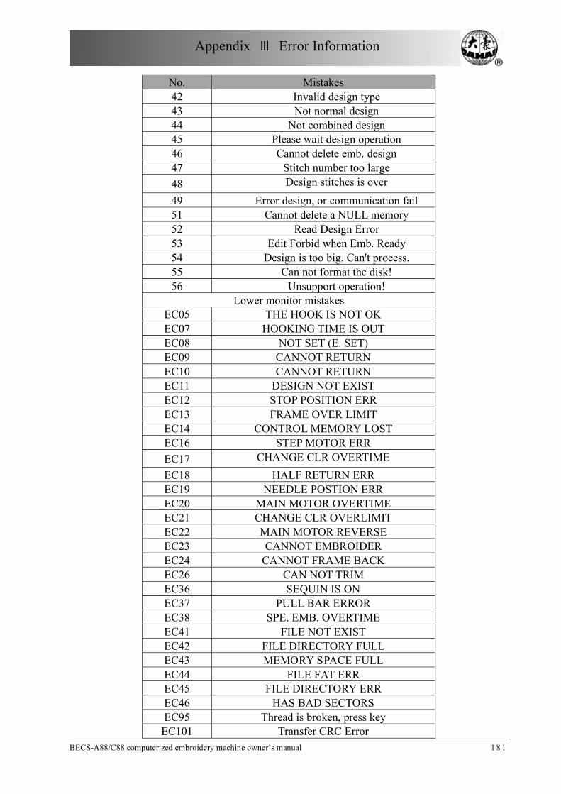
Appendix Ⅲ Error Information
BECS-A88/C88 computerized embroidery machine owner’s manual 1 8 1
No. Mistakes 42 Invalid design type 43 Not normal design 44 Not combined design 45 Please wait design operation 46 Cannot delete emb. design 47 Stitch number too large 48 Design stitches is over 49 Error design, or communication fail 51 Cannot delete a NULL memory 52 Read Design Error 53 Edit Forbid when Emb. Ready 54 Design is too big. Can't process. 55 Can not format the disk! 56 Unsupport operation!
Lower monitor mistakes EC05 THE HOOK IS NOT OK EC07 HOOKING TIME IS OUT EC08 NOT SET (E. SET) EC09 CANNOT RETURN EC10 CANNOT RETURN EC11 DESIGN NOT EXIST EC12 STOP POSITION ERR EC13 FRAME OVER LIMIT EC14 CONTROL MEMORY LOST EC16 STEP MOTOR ERR EC17 CHANGE CLR OVERTIME EC18 HALF RETURN ERR EC19 NEEDLE POSTION ERR EC20 MAIN MOTOR OVERTIME EC21 CHANGE CLR OVERLIMIT EC22 MAIN MOTOR REVERSE EC23 CANNOT EMBROIDER EC24 CANNOT FRAME BACK EC26 CAN NOT TRIM EC36 SEQUIN IS ON EC37 PULL BAR ERROR EC38 SPE. EMB. OVERTIME EC41 FILE NOT EXIST EC42 FILE DIRECTORY FULL EC43 MEMORY SPACE FULL EC44 FILE FAT ERR EC45 FILE DIRECTORY ERR EC46 HAS BAD SECTORS EC95 Thread is broken, press key
EC101 Transfer CRC Error

Appendix Ⅲ Error Information
182 BECS-A88/C88 computerized embroidery machine owner’s m a n u a l