conceptpower dpa 500 100 - 500 kw user manual€¦ · · 2016-11-09this symbol in conjunction...
TRANSCRIPT
Conceptpower DPA 500 100 - 500 kW
User Manual
04-3275_OPM_ABB_CONCEPTPOWER_DPA_500kW_EN_REV-A.docx
© Copyright 2016 ABB, All rights reserved.

04-3275_OPM_ABB_CONCEPTPOWER_DPA_500kW_EN_REV-A.docx Page 2/78 ABB
Modifications reserved
DOCUMENT INFORMATION
File name : 04-3275_OPM_ABB_CONCEPTPOWER_DPA_500kW_EN_REV-A.docx
UPS model : Conceptpower DPA 500 Date of issue : 03.05.2016
Article number : 04-3275
Document number : 4NWD003263
Revision : A
FOREWORD
The UPS system operates with mains, battery or bypass power. It contains components that carry high currents and voltages. The properly installed UPS system is grounded to earth and IP 20 rated against electrical shock and foreign objects.
OPERATIONS INSIDE THE UPS MUST BE PERFORMED BY A SERVICE ENGINEER FROM THE SUPPLIER OR FROM AN AGENT CERTIFIED BY THE SUPPLIER.
This user manual contains guidelines to check delivery, installing and commissioning of the UPS and is intended for people who plan the installation, install, commission and use or service the UPS. The reader is expected to know the fundamentals of electricity, wiring, electrical components and electrical schematic symbols.
The instructions in this manual MUST be followed TO PERFORM ANY OPERATION ON THE UPS.
04-3275_OPM_ABB_CONCEPTPOWER_DPA_500kW_EN_REV-A.docx Page 3/78 ABB
Modifications reserved
LIST OF SYMBOLS
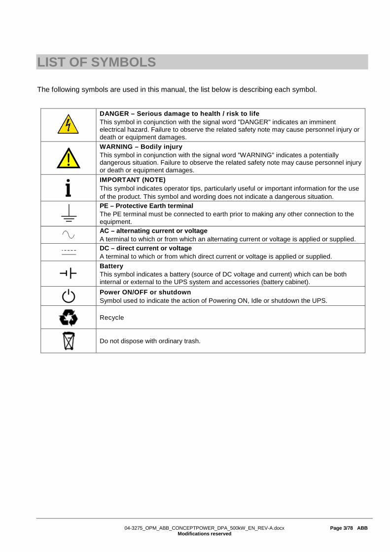
The following symbols are used in this manual, the list below is describing each symbol.
DANGER – Serious damage to health / risk to life This symbol in conjunction with the signal word "DANGER" indicates an imminent electrical hazard. Failure to observe the related safety note may cause personnel injury or death or equipment damages.
WARNING – Bodily injury This symbol in conjunction with the signal word "WARNING" indicates a potentially dangerous situation. Failure to observe the related safety note may cause personnel injury or death or equipment damages.
IMPORTANT (NOTE) This symbol indicates operator tips, particularly useful or important information for the use of the product. This symbol and wording does not indicate a dangerous situation.
PE – Protective Earth terminal The PE terminal must be connected to earth prior to making any other connection to the equipment.
AC – alternating current or voltage A terminal to which or from which an alternating current or voltage is applied or supplied.
DC – direct current or voltage A terminal to which or from which direct current or voltage is applied or supplied.
Battery This symbol indicates a battery (source of DC voltage and current) which can be both internal or external to the UPS system and accessories (battery cabinet).
Power ON/OFF or shutdown Symbol used to indicate the action of Powering ON, Idle or shutdown the UPS.
Recycle
Do not dispose with ordinary trash.

04-3275_OPM_ABB_CONCEPTPOWER_DPA_500kW_EN_REV-A.docx Page 4/78 ABB
Modifications reserved
CONTENTS DOCUMENT INFORMATION ...................................................................................................... 2
FOREWORD ............................................................................................................................... 2
LIST OF SYMBOLS .................................................................................................................... 3
1 SAFETY INSTRUCTIONS .................................................................................................. 7
2 GENERAL CHARACTERISTICS ........................................................................................ 8 2.1 ENVIRONMENTAL REQUIREMENTS .............................................................................. 8 2.2 CE MARKING AND DECLARATION OF SAFETY AND EMC CONFORMITY .................. 8 2.3 INQUIRIES ........................................................................................................................ 8 2.4 TYPE PLATE AND MODEL IDENTIFICATION ................................................................. 9 2.5 CONCEPTPOWER DPATM 500 BASIC SYSTEM CONFIGURATION ........................... 10 2.6 MULTIPLE CABINET CONFIGURATION ........................................................................ 11
3 TRANSPORT – STORAGE – UNPACKING ..................................................................... 12 3.1 VISUAL INSPECTION ..................................................................................................... 12 3.2 STORAGE ...................................................................................................................... 12 3.3 UNPACKING ................................................................................................................... 13
4 INSTALLATION AND WIRING ......................................................................................... 14 4.1 POSITIONING OF THE UPS AND BATTERY CABINET ................................................ 14 4.2 ELECTRICAL INSTALLATION ........................................................................................ 15 4.3 WIRING CONFIGURATIONS .......................................................................................... 16
4.3.1 Single input feed – separate batteries configuration ......................................................... 17 4.3.2 Dual input feed – common battery configuration ............................................................... 18 4.3.3 AC Wiring instructions ....................................................................................................... 19 4.3.4 DC Wiring instructions ....................................................................................................... 22 4.3.5 Installation Checklist .......................................................................................................... 24
4.4 FRONT VIEW.................................................................................................................. 25
5 CONNECTIVITY ................................................................................................................ 26 5.1 INTERFACING ................................................................................................................ 26
5.1.1 SMART PORT JD1 on each frame (Serial RS 232 / Sub D9 / male) ................................ 26 5.1.2 Customer interface and DRY PORTs (volt-free contacts) ................................................. 27 5.1.3 JD1 / RS232 PC / Laptop Interface .................................................................................. 28 5.1.4 USB PC / Laptop Interface ................................................................................................ 28 5.1.5 JR2 / RS232 Interface for Multidrop .................................................................................. 28 5.1.6 Optional feature: Configuration of the External Output Breaker ........................................ 28
6 OPERATION ..................................................................................................................... 30 6.1 COMMISSIONING .......................................................................................................... 30 6.2 MULTI-CABINET CONFIGURATION .............................................................................. 30
6.2.1 Installation Instructions ...................................................................................................... 31 6.2.2 Paralleling of UPS-Cabinets .............................................................................................. 31 6.2.3 DIP Switch SW1-6 ............................................................................................................. 32 6.2.4 Multidrop Configuration ..................................................................................................... 33
04-3275_OPM_ABB_CONCEPTPOWER_DPA_500kW_EN_REV-A.docx Page 5/78 ABB
Modifications reserved
6.2.5 ON/OFF – Main Buttons .................................................................................................... 33 6.2.6 Parallel Isolator (IA2) ......................................................................................................... 34 6.2.7 Maintenance Bypass (IA1) ................................................................................................ 34 6.2.8 ECO-MODE (BYPASS MODE) in Parallel Systems ......................................................... 34
6.3 COMMISSIONING OF MULTI-CABINET CONFIGURATION .......................................... 35 6.3.1 Start-up of a Multi-Cabinet Configuration .......................................................................... 35 6.3.2 Shutdown of Multi-Cabinet Configuration .......................................................................... 35
6.4 SYSTEM DISPLAY ......................................................................................................... 35 6.4.1 Graphical display operation ............................................................................................... 36 6.4.2 Rear View .......................................................................................................................... 36 6.4.3 Start up and installation ..................................................................................................... 37 6.4.4 Navigation .......................................................................................................................... 37 6.4.5 Mimic Diagram – system level ........................................................................................... 38 6.4.6 Module selection screen .................................................................................................... 39 6.4.7 Home screen ..................................................................................................................... 40 6.4.8 Operating mode ................................................................................................................. 43
6.5 MODULE DISPLAY – CONTROL PANEL ....................................................................... 44 6.5.1 LED Indicators ................................................................................................................... 45 6.5.2 Buttons ............................................................................................................................... 45 6.5.3 ON/OFF Start-up and Shutdown Buttons .......................................................................... 46 6.5.4 Definition of a Single/Parallel-Module System .................................................................. 46 6.5.5 Definition of a Single/ Multi-Cabinet Chain (DIP Switch SW1-6) ....................................... 46 6.5.6 Status Screens .................................................................................................................. 46 6.5.7 Main Menu Screen............................................................................................................. 47 6.5.8 Event Log Screen .............................................................................................................. 47 6.5.9 Measurements Screen ...................................................................................................... 48 6.5.10 Commands Screen ............................................................................................................ 48 6.5.11 UPS Data ........................................................................................................................... 49 6.5.12 Set-Up User ....................................................................................................................... 49 6.5.13 Set-Up Service ................................................................................................................... 49
6.6 OPERATING MODES ..................................................................................................... 50 6.6.1 Mode "ON LINE" (INVERTER MODE) .............................................................................. 50 6.6.2 Mode"OFF-LINE"(ECO- or BYPASS MODE) .................................................................... 50 6.6.3 "MAINTENANCE BYPASS" - Mode .................................................................................. 50 6.6.4 Output Switch/Parallel Isolator (IA2).................................................................................. 51
6.7 START-UP PROCEDURE............................................................................................... 52 6.8 SHUTDOWN PROCEDURE ........................................................................................... 54 6.9 LOAD TRANSFER: FROM INVERTER OPERATION TO MAINTENANCE BYPASS ...... 55 6.10 LOAD TRANSFER: FROM MAINTENANCE BYPASS TO INVERTER OPERATIONS ... 56 6.11 REPLACEMENT OF UPS MODULES ............................................................................. 57
6.11.1 Replacement of UPS-Module in Single-Module systems .................................................. 57 6.11.2 Replacement of UPS-Module in Redundant Multi-Module systems ................................. 57
7 MAINTENANCE ................................................................................................................ 59 7.1 USER RESPONSIBILITIES ............................................................................................. 59 7.2 PREVENTATIVE MAINTENAINCE ................................................................................. 59 7.3 DEEP BATTERY TEST ................................................................................................... 59 7.4 BATTERY MAINTENANCE, DISPOSAL AND RECYCLING ........................................... 60

04-3275_OPM_ABB_CONCEPTPOWER_DPA_500kW_EN_REV-A.docx Page 6/78 ABB
Modifications reserved
8 TROUBLESHOOTING ...................................................................................................... 61 8.1 ALARMS ......................................................................................................................... 61 8.2 FAULT IDENTIFICATION AND RECTIFICATION ........................................................... 61
9 OPTIONS .......................................................................................................................... 62 9.1 INTRODUCTION ............................................................................................................. 62 9.2 REMOTE SHUT DOWN (EPO) ....................................................................................... 62 9.3 GENERATOR ON FACILITIES ....................................................................................... 63 9.4 WAVEMON SHUTDOWN AND MANAGEMENT SOFTWARE ........................................ 63
9.4.1 Why is UPS Management important? ............................................................................... 63 9.4.2 WAVEMON Shutdown and monitoring software ............................................................... 63 9.4.3 SNMP CARD/ADAPTER for network management / remote monitoring .......................... 65
10 TECHNICAL SPECIFICATIONS ....................................................................................... 67 10.1 CONCEPTPOWER DPA 500 - SYSTEM DESCRIPTION ............................................... 67 10.2 GENERAL CHARACTERISTICS .................................................................................... 68 10.3 INPUT CHARACTERISTICS ........................................................................................... 70 10.4 OUTPUT CHARACTERISTICS ....................................................................................... 71 10.5 BATTERY CHARACTERISTICS ..................................................................................... 72
10.5.1 Graph: AC / AC efficiency with linear load @ cos(phi) 1 * ................................................ 72 10.6 USER INTERFACE - COMMUNICATION ....................................................................... 73
10.6.1 System Display .................................................................................................................. 73 10.6.2 DPA Display ....................................................................................................................... 74 10.6.3 Mimic Diagram ................................................................................................................... 74
10.7 CUSTOMER INTERFACES ............................................................................................ 74 10.7.1 Customer inputs dry ports: Terminal blocks X3 / 3-14 ..................................................... 74 10.7.2 Outputs dry ports: Terminal blocks X2 + X3 / 1-2 ............................................................ 74 10.7.3 Interlock castell function: Terminal block X1 ..................................................................... 75
10.8 OPTIONS ........................................................................................................................ 77 10.9 ON REQUEST ................................................................................................................ 77 10.10 INSTALLATION PLANNING – UPS POSITIONING ........................................................ 77 10.11 HEAT DISSIPATION ....................................................................................................... 77 10.12 SINGLE INPUT FEED – SEPARATE BATTERIES CONFIGURATION ........................... 78 10.13 DUAL INPUT FEED – COMMON BATTERY CONFIGURATION .................................... 79
11 REVISION HISTORY ........................................................................................................ 80

04-3275_OPM_ABB_CONCEPTPOWER_DPA_500kW_EN_REV-A.docx Page 7/78 ABB
Modifications reserved
1 SAFETY INSTRUCTIONS
The user must follow the precautions and only perform the described operations. Also in these measures, the operator of the UPS system must adhere to the instructions in this manual. Any deviations from the instructions could be dangerous to the user or cause accidental load loss. The only user operations permitted are:
• Use of the LCD control panel (LCD Display) and Maintenance Bypass
• Start up and shut down of the UPS (excluding the commissioning start up)
• Operation of additional connectivity devices (remote monitoring, SNMP card access and programming)
In order to operate the UPS (and accessories such as battery cabinets) safely, it is recommended to read this manual firstly and then follow the instructions carefully during any operation on the UPS. Read carefully all instructions and save this manual for future reference. THE MANUFACTURER DOES NOT TAKE ANY RESPONSIBILITY FOR DAMAGES CAUSED THROUGH WRONG MANIPULATIONS OF THE UPS SYSTEM.
DANGER
IT IS PROHIBITED TO REMOVE ANY SCREWS FROM THE UPS SYSTEM OR FROM THE BATTERY CABINET (IF PRESENT). DANGER OF ELECTRICAL SHOCK.
DANGER
HIGH FAULT CURRENTS (LEAKAGE CURRENTS). BEFORE CONNECTING THE UPS TO THE MAINS, YOU MUST ENSURE THAT THERE IS A PROPER PE – PROTECTIVE EARTH – CONNECTION
DANGER
THE USER MUST DISPLAY A WARNING SHIELD ON ALL PRIMARY UPS CIRCUIT BREAKERS. THE SERVICE PERSONNEL HAS TO BE INFORMED ABOUT DANGEROUS VOLTAGES. THE WARNING PANELS MUST CONTAIN THE FOLLOWING TEXT: “BEFORE STARTING WITH THE MAINTENANCE WORK ON THE CIRCUIT BREAKERS, MAKE SURE THE UPS IS ISOLATED.”

04-3275_OPM_ABB_CONCEPTPOWER_DPA_500kW_EN_REV-A.docx Page 8/78 ABB
Modifications reserved
2 GENERAL CHARACTERISTICS
2.1 ENVIRONMENTAL REQUIREMENTS To operate the UPS at the best efficiency point, your installation site should meet the environmental parameters outlined in this manual. Excessive amount of dust or moisture in the operating environment may cause damage or lead to malfunction. The UPS should be always protected from the outside weather and sunshine. The operating environment must meet the weight, airflow, size and clearance requirements specified in the section 10 “technical specifications” of this manual or in the technical datasheet of the same product (separate document).
Under no circumstances, the UPS should be installed in an airtight room, in the presence of flammable gases, or in an environment, exceeding environmental requirements specified here below.
The ambient temperature for operating the UPS must be in the range 0 °C to +40 °C. The Ideal temperature also recommended to achieve a long life of the UPS and VRLA batteries is +20°C to +25°C. The relative humidity should be below 95% (non-condensing) and the max. altitude without de-rating is 1000m above sea level.
2.2 CE MARKING AND DECLARATION OF SAFETY AND EMC CONFORMITY The product has the CE marking in compliance with the following European directives
• Low Voltage Directive: 2006/95/EC • EMC Directive: 2004/108/EC
The product applies the actual UPS standards, listed in the Table 1 below.
Table 1: UPS Standards.
Description Product standards General standards
Safety IEC/EN 62040-1 IEC/EN 60950-1
Electromagnetic Compatibility (EMC) IEC/EN 62040-2
IEC/EN 61000-4-2 IEC/EN 61000-4-3 IEC/EN 61000-4-4 IEC/EN 61000-4-5 IEC/EN 61000-4-6 IEC/EN 61000-4-8 IEC/EN 61000-2-2
2.3 INQUIRIES Address inquiries about the UPS to the local office or agent certified by the supplier. Please note the type code and the serial number – shown in the type plate of the product (see section 2.4) – of the equipment and contact your nearest agent certified by the supplier.
04-3275_OPM_ABB_CONCEPTPOWER_DPA_500kW_EN_REV-A.docx Page 9/78 ABB
Modifications reserved
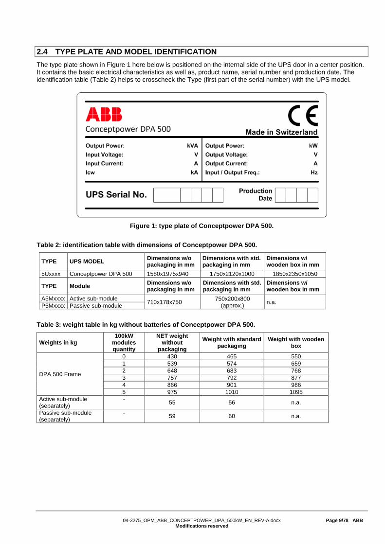
2.4 TYPE PLATE AND MODEL IDENTIFICATION The type plate shown in Figure 1 here below is positioned on the internal side of the UPS door in a center position. It contains the basic electrical characteristics as well as, product name, serial number and production date. The identification table (Table 2) helps to crosscheck the Type (first part of the serial number) with the UPS model.
Figure 1: type plate of Conceptpower DPA 500.
Table 2: identification table with dimensions of Conceptpower DPA 500.
TYPE UPS MODEL Dimensions w/o packaging in mm
Dimensions with std. packaging in mm
Dimensions w/ wooden box in mm
5Uxxxx Conceptpower DPA 500 1580x1975x940 1750x2120x1000 1850x2350x1050
TYPE Module Dimensions w/o packaging in mm
Dimensions with std. packaging in mm
Dimensions w/ wooden box in mm
A5Mxxxx Active sub-module 710x178x750 750x200x800 (approx.) n.a. P5Mxxxx Passive sub-module
Table 3: weight table in kg without batteries of Conceptpower DPA 500.
Weights in kg 100kW
modules quantity
NET weight without
packaging Weight with standard
packaging Weight with wooden
box
DPA 500 Frame
0 430 465 550 1 539 574 659 2 648 683 768 3 757 792 877 4 866 901 986 5 975 1010 1095
Active sub-module (separately)
- 55 56 n.a.
Passive sub-module (separately)
- 59 60 n.a.

04-3275_OPM_ABB_CONCEPTPOWER_DPA_500kW_EN_REV-A.docx Page 10/78 ABB
Modifications reserved
2.5 CONCEPTPOWER DPATM 500 BASIC SYSTEM CONFIGURATION The UPS system is housed in single freestanding cabinet. The cabinets line up and match in style and colour, and have safety shields behind the doors for hazardous voltage protection. Following configurations are possible of single cabinet configuration:
Table 4: single cabinet configuration possibilities.
Nominal power 100kW Nominal power 200kW
Nominal power 300kW Nominal power 400kW
Nominal power 500kW
04-3275_OPM_ABB_CONCEPTPOWER_DPA_500kW_EN_REV-A.docx Page 11/78 ABB
Modifications reserved
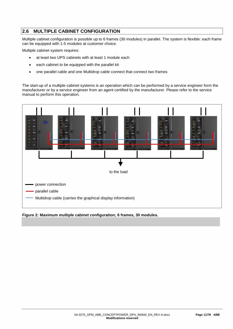
2.6 MULTIPLE CABINET CONFIGURATION Multiple cabinet configuration is possible up to 6 frames (30 modules) in parallel. The system is flexible: each frame can be equipped with 1-5 modules at customer choice.
Multiple cabinet system requires:
• at least two UPS cabinets with at least 1 module each
• each cabinet to be equipped with the parallel kit
• one parallel cable and one Multidrop cable connect that connect two frames
The start-up of a multiple cabinet systems is an operation which can be performed by a service engineer form the manufacturer or by a service engineer from an agent certified by the manufacturer. Please refer to the service manual to perform this operation.
power connection
parallel cable
Multidrop cable (carries the graphical display information)
Figure 2: Maximum multiple cabinet configuration; 6 frames, 30 modules.
to the load

04-3275_OPM_ABB_CONCEPTPOWER_DPA_500kW_EN_REV-A.docx Page 12/78 ABB
Modifications reserved
3 TRANSPORT – STORAGE – UNPACKING
3.1 VISUAL INSPECTION Upon receiving the goods, make sure that they corresponds to the material indicated in the delivery note. Carefully examine the packed unit(s) for any sign of physical damage. Two TiltWatch indicators (see Figure 3) are placed on two sides of the packed unit, in a well visible position. They should both be intact and not red color. If tipping has occurred the white arrow becomes red, like shown on the Figure 3 below.
In case of damaged unit(s) or even only suspect of damaged (TiltWatch is red) inform immediately: • The carrier • The manufacturer
IMPORTANT NOTES
VISIBLE TRANSPORT DAMAGES MUST BE CLAIMED TO THE CARRIER IMMEDIATELY AFTER RECEIPT. OTHER CLAIM FOR SHIPPING DAMAGE MUST BE FILED ALSO IMMEDIATELY AND THE CARRIER MUST BE INFORMED WITHIN 7 DAYS OF RECEIPT OF THE EQUIPMENT. THE PACKING MATERIALS SHOULD BE STORED FOR FURTHER INVESTIGATION.
Figure 3: TiltWatch indicator: left when intact and right when tipping has occurred.
3.2 STORAGE The packing of the goods protects it from mechanical and environmental damage. UPS and Battery cabinets should be store in its original packaging. Make sure that the goods are stored indoor, protected from water and sunshine in a clean environment.
IMPORTANT NOTES
THE RECOMMENDED TEMPERATURE FOR STORAGE OF THE UPS SYSTEM AND BATTERIES IS BETWEEN +20 °C AND +25°C, HUMIDITY < 95% (NON-CONDENSING). FOR UPS SYSTEM ONLY THE STOREAGE TEMPERATURE CAN BE BETWEEN -25 °C AND +70°C, HUMIDITY < 95% (NON-CONDENSING). BEFORE SWITCHING ON THE UNIT(S), MAKE SURE THE AMBIENT TEMPERATURE HAS REACHED THE OPERATION TEMPERATURE RANGE WHICH IS 0°C - +40°C. SEALED BATTERIES MUST NEVER BE STORED IN A DISCHARGED OR PARTIALLY DISCHARGED STATE. EXTREME TEMPERATURE, UNDER- AND OVERCHARGE AND OVERDISCHARGE WILL DESTROY BATTERIES!
If the UPS is delivered without batteries, the manufacturer is not responsible for any damage or malfunctioning caused to the UPS by incorrect wiring. For long-term storage make sure that the battery is fully recharged every 6 months. Before and after storing, charge the battery.

04-3275_OPM_ABB_CONCEPTPOWER_DPA_500kW_EN_REV-A.docx Page 13/78 ABB
Modifications reserved
3.3 UNPACKING Prior unpacking make sure that the floor surface is solid and suitable for supporting the weight of all the equipment. The UPS and accessories are delivered on a specifically designed pallet that allowing to move it with a forklift or a pallet jack. Bring the unit(s) close to the end position and unpack them by removing the packing and shipping materials as described next.
WARNING
CENTER of GRAVITY
WEIGHT (kg)
UPS AND BATTERY CABINETS ARE HEAVY AND TALL. MAKE SURE YOU ARE ALWAYS WORKING SAFELY BY USING APPROPIRATE TOOLS AND EQUIPMENT. WHEN MOVING THE UNITS AROUND USING FORKLIFT, ALWAYS MAKE SURE THE UNITS ARE IN UPRIGHT POSITION AND MOVE WITH SLOW SPEED AND SLOW ACCELERATIONS. WHEN MOVING THE EQUIPMENT ALWAYS REFER TO THE CENTER OF GRAVITY (COG) LABEL. WHICH MAY NOT BE IN ALWAYS IN THE MIDDLE (SEE FIGURE ON THE LEFT). DPA 500 EQUIPPED WITH 1-2 MODULES HAVE THE COG IN THE MIDDLE OR CLOSE TO IT, WHEREAS A DPA 500 WITH 3-5 MODULES HAS THE SHIFTED TO THE SIDE.
Perform the following steps to unpack the UPS equipment from the standard packaging:
1) and 2) Using a forklift load the unit by paying attention to the COG (see the warning above) and bring the unit(s) close to the end position.
3) Remove the plastic film from the UPS, by cutting it on one edge (where there is the cardboard underneath). Remove the 4x cardboard edges carefully by paying attention that the accessory box placed on top of the UPS does not fall down. Lower the accessory box with the help of a stool or ladder; make sure you remain safe.
4) After having placed the UPS in its final position, disassemble the left and right dedicated transportation socket.
5) You may want to keep all packaging materials for later use.
1) 2)
3) 2)
Figure 4: Photographs of Conceptpower DPA with standard packaging.

04-3275_OPM_ABB_CONCEPTPOWER_DPA_500kW_EN_REV-A.docx Page 14/78 ABB
Modifications reserved
4 INSTALLATION AND WIRING
4.1 POSITIONING OF THE UPS AND BATTERY CABINET The UPS is designed for location in a restricted access location only and should be located where:
• The relative humidity does not exceed 95% (non-condensing) and the temperature remains always between 0°C and +40°C. Note: an optimal temperature for the UPS and especially for VRLA batteries is 20°C- 25°C. The UPS room shall have temperature control (air-cooling)
• Any kind of dust or corrosive/explosive gases must be absent
• Fire protection standards are respected
• The place is vibration free
• The floor material should be non-flammable and strong enough to support the heavy load.
• Cabling can be performed easily
• Available front accessibility of 1m from front of the unit for service or maintenance
• Only front access is necessary for service and maintenance
• If the UPS will be installed in bayed enclosures, partition walls have to be installed as well
Also the needed clearances to allow proper airflow on the UPS system and to allow proper service and maintenance shall be respected as reported in the Tables 5 and 6 here below.
Table 5: minimum clearances for single UPS installation.
UPS Model A1 (mm)
B1
(mm) C (°)
D (mm)
DPA 500 300 1000 115° 400
Table 6: minimum clearances for UPS + other cabinets in row.
UPS Model A2 (mm)
B2
(mm) C (°)
D (mm)
DPA 500 300 1000 115° 400
Figure 5: top view and indication of the Figure 6: Top view and indication of the minimum minimum clearances for single UPS. clearances for UPS + other cabinets in row.
Accessibility Totally front accessibility for service and maintenance
Positioning Min. 30 cm rear space (required for fan)
Input and Output Power Cabling From the front bottom or top
B1
A1
UPS Cabinet
door opening
C
D top clearance is only needed if there is no side clearance.
B2
UPS Cabinet
A2
Battery cabinet or other equipment
Battery cabinet or other equipment
door opening
C

04-3275_OPM_ABB_CONCEPTPOWER_DPA_500kW_EN_REV-A.docx Page 15/78 ABB
Modifications reserved
4.2 ELECTRICAL INSTALLATION The electrical installation procedure is described in the following. The installation inspection and initial start-up of the UPS and extra battery cabinet must be carried out by a qualified service personnel such as a licensed service engineer from the manufacturer or from an agent certified by the manufacturer.
WARNING
THE INSTRUCTION IN THIS USER MANUAL HAVE ALWAYS TO BE FOLLOWED IN ORDER TO AVOID INJURIES FROM ELECTRICAL IMPACTS.
WARNING
ALL THE OPERATIONS IN THIS MANUAL MUST BE PERFORMED BY AUTHORISED ELECTRICIANS OR BY QUALIFIED INTERNAL PERSONNEL.
DO NOT OPERATE IN CASE OF PRESENCE OF WATER OR MOISTURE.
BY OPENING OR REMOVING THE FRONT COVERS BEHIND THE UPS DOOR, YOU RUN RISK OF EXPOSURE TO HAZARDOUS VOLTAGES.
PHYSICAL INJURY OR DEATH MAY FOLLOW, OR DAMAGE MAY OCCUR TO THE UPS, OR THE LOAD EQUIPMENT IF THESE INSTRUCTIONS ARE IGNORED.
To ensure correct operation of the UPS and its ancillary equipment it is necessary to provide the appropriate wiring and with fuse protection in accordance with the prescribed local standards or with the local regulations/law. Alternatively refer to the suggested appropriate wiring and fuse protection in the next subsections 4.3.
The UPS unit has the following power connections:
Rectifier input: three-phase (1-L1, 1-L2, 1-L3) Bypass input :three-phase (2-L1, 2-L2, 2-L3) Neutral (N) The Neutral connection at UPS input (upstream) is mandatory. Load output : three-phase (3-L1, 3-L2, 3-L3) Battery: (+) and (-) Note: The battery (-) is at the same potential and is the same connection point as N. Protective earth (PE)
IMPORTANT NOTES
INPUT NEUTRAL IS REQUIRED TO OPERATE THE RECTIFIER.
In TN-S Systems, no 4-pole input switches or circuit breakers should be used. If you have to use for other reason a 4-pole switch, you have to be aware that, when open, the system - UPS and all downstream equipment - are floating against the PE.
0V 230V
UPS

04-3275_OPM_ABB_CONCEPTPOWER_DPA_500kW_EN_REV-A.docx Page 16/78 ABB
Modifications reserved
4.3 WIRING CONFIGURATIONS Conceptpower DPA 500 can be wired in different configurations.
The AC wiring (rectifier input, bypass input and output) has the following possibilities: • DITE - Dual Input Top Entry (Dual Input is optional) • DIBE - Dual Input Bottom Entry (Dual Input is optional) • SITE - Single Input Top Entry • SIBE - Single Input Bottom Entry
Simultaneously, the DC wiring (battery) has the following possibilities: • CBTE - Common Battery Top Entry (Common battery is optional) • CBBE - Common Battery Bottom Entry (Common battery is optional) • SBTE - Separate Battery Top Entry • SBBE - Separate Battery Bottom Entry
When combining top entry and bottom entry (e.g. AC Top and DC bottom, or AC bottom and DC top) there is an additional gland plate which can be ordered as option (highly recommended!). One gland plate is included as standard. The gland plate is shown in the figure below on the left side, the right side shows the indicative positions when having top and bottom cable entry.
Figure 7: gland plate and its indicative position on the Conceptpower DPA 500 Frame.
Before proceeding to wire the unit, make sure that the unit is pre-configured exactly as you need.
IMPORTANT NOTE!
The Conceptpower DPA 500 Frame is pre-configured at the factory exactly as ordered. All combinations of the above AC wiring and DC wiring configurations can be ordered, therefore it is very important to order the correct AC and DC wiring configurations, which cannot be changed on site. The manufacturer declines any responsibility due to not appropriate mounting/dismounting of the frame-internal busbar of the unit.
!

04-3275_OPM_ABB_CONCEPTPOWER_DPA_500kW_EN_REV-A.docx Page 17/78 ABB
Modifications reserved
4.3.1 Single input feed – separate batteries configuration
Figure 8: Block diagram of DPA 500 with single input feed and separate batteries configuration.
Table 7: Recommended AC wiring (copper wires) according to IEC 60950-1, recommended fuse ratings for slow line fuses (gL) or circuit breakers (CB), connection terminal size and max. tightening torque.
Rated power (kW)
Single input Max. rectifier input current with charging batt. 835A at 230V / 875A at 220V
Output Rated output current in normal conditions 725A at 230V / 758A at 220V
Fuse A Type: gL or CB (quantity x A)
Cable A (quantity x mm2)
Fuse D Type: gL or CB (only needed in parallel system) (quantity x mm2)
Cable D (quantity x mm2)
500
3 x 1000A (3 pole, bolded N)
5x(2x240) 5x(3x120)
4 x 800A (4 pole)
5x(2x240) 5x(3x120)
All connection points are bus-bar, M12. Recommended tightening torque 42 Nm
Table 8: Recommended DC wiring (copper wires) according to IEC 60950-1, recommended fuse ratings for fast acting fuses (gR) or circuit breakers (CB), connection terminal size and max. tightening torque.
Separate batteries
Rated power (kW)
Fuse E Type: gR or CB (quantity x A)
Cable E (quantity x mm2)
100 (one module)
2 x 250A (2 pole)
2x(1x120) with 40-45 12V battery blocks 2x(1x95) with 46-50 12V battery blocks
All connection points are bus-bar, M8. Recommended tightening torque 24 Nm
04-3275_OPM_ABB_CONCEPTPOWER_DPA_500kW_EN_REV-A.docx Page 18/78 ABB
Modifications reserved
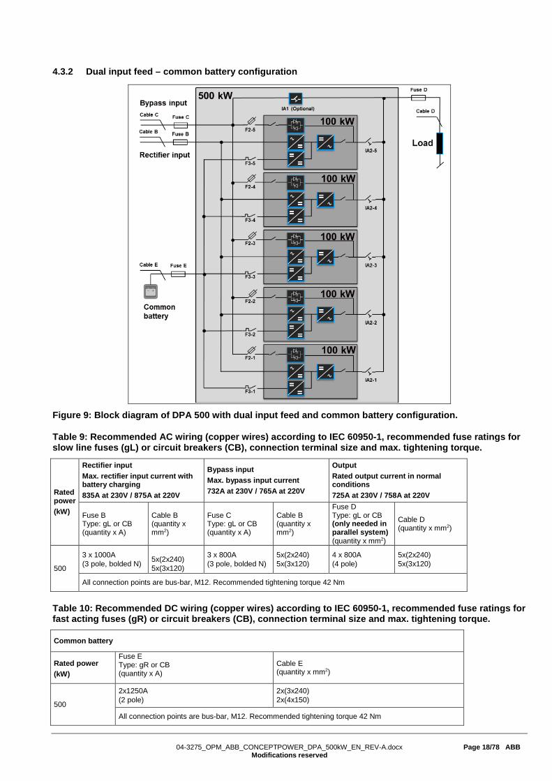
4.3.2 Dual input feed – common battery configuration
Figure 9: Block diagram of DPA 500 with dual input feed and common battery configuration.
Table 9: Recommended AC wiring (copper wires) according to IEC 60950-1, recommended fuse ratings for slow line fuses (gL) or circuit breakers (CB), connection terminal size and max. tightening torque.
Rated power (kW)
Rectifier input Max. rectifier input current with battery charging 835A at 230V / 875A at 220V
Bypass input Max. bypass input current 732A at 230V / 765A at 220V
Output Rated output current in normal conditions 725A at 230V / 758A at 220V
Fuse B Type: gL or CB (quantity x A)
Cable B (quantity x mm2)
Fuse C Type: gL or CB (quantity x A)
Cable B (quantity x mm2)
Fuse D Type: gL or CB (only needed in parallel system) (quantity x mm2)
Cable D (quantity x mm2)
500
3 x 1000A (3 pole, bolded N)
5x(2x240) 5x(3x120)
3 x 800A (3 pole, bolded N)
5x(2x240) 5x(3x120)
4 x 800A (4 pole)
5x(2x240) 5x(3x120)
All connection points are bus-bar, M12. Recommended tightening torque 42 Nm
Table 10: Recommended DC wiring (copper wires) according to IEC 60950-1, recommended fuse ratings for fast acting fuses (gR) or circuit breakers (CB), connection terminal size and max. tightening torque.
Common battery
Rated power (kW)
Fuse E Type: gR or CB (quantity x A)
Cable E (quantity x mm2)
500
2x1250A (2 pole)
2x(3x240) 2x(4x150)
All connection points are bus-bar, M12. Recommended tightening torque 42 Nm

04-3275_OPM_ABB_CONCEPTPOWER_DPA_500kW_EN_REV-A.docx Page 19/78 ABB
Modifications reserved
4.3.3 AC Wiring instructions
Before proceeding to wire the UPS, make sure that you have read and understood the chapter above 4.2 Electrical installation and make sure that the following is respected:
• The cable sections and fuse ratings are respecting the local standards. Alternatively, you can use the recommended cable sections and fuse rating in the tables 7 and 9, which are according to (IEC 60950-1).
• No mains voltage is present on the wires
• All Loads are shut down and disconnected
• UPS is shut down and voltage-free (no battery is connected)
• All modules are correctly inserted and bolded on the frame
• The maintenance bypass switch IA1 (if present) is in position OFF (open)
• All 5xparallel isolators IA2-1, IA2-2, IA2-3, IA2-4, IA2-5 are in position OFF
• Mains voltage (Input Voltage) and frequency (Input Freq.) correspond to the values indicated on the type plate of the UPS. The type plate (Figure 1) is on the inside part of the door in a center position.
• Make sure that the total power of the load is equal or lower than the rated power of the UPS (Output power) indicated on the type plate of the UPS.
• PE wiring is performed in accordance with the prescribed IEC Standards or with local regulations;
• UPS is connected to the mains through a Low Voltage (LV)-Distribution Board with a separate mains line (protected with a circuit breaker or fuse) for the UPS.
• A torque wrench is used to tighten the cables, the recommended torque is indicated in tables 7 and 9.
The figures below show the I/O terminals, bottom cable entry on the left and top cable entry on the right.
Front-side view of the bottom I/O terminals w/o wires.
Front-side view of the top I/O terminals w/o wires.
BATT- BATT+ 3-L3
3-L2 3-L1
2-L3 2-L2
2-L1
1-L3 1-L2
1-L1
PE
N 3-L3 2-L3 1-L3 3-L2 2-L2 1-L2
1-L1 2-L1 3-L1 PE N
BATT+ BATT-

04-3275_OPM_ABB_CONCEPTPOWER_DPA_500kW_EN_REV-A.docx Page 20/78 ABB
Modifications reserved
The AC wiring must be done in the following order:
1. Connect first the PE wire coming from the LV Distribution Board (mains) to the terminal labelled "PE". (for simplicity only the bottom cable entry is shown here, the bars for top entry are positioned the same but mirrored bottom-top)
Bottom cable entry Top cable entry
2. SINGLE INPUT FEED - Connect the input wires 3-phases + N coming from the LV Distribution Board
(mains), by referring to the table here below. Keep the phase rotation in clock-wise sense.
MAINS INPUT CABLE UPS BUSBAR Phase L1 1-L1 Phase L2 1-L2 Phase L3 1-L3 NEUTRAL N EARTH PE
Bottom cable entry Top cable entry

04-3275_OPM_ABB_CONCEPTPOWER_DPA_500kW_EN_REV-A.docx Page 21/78 ABB
Modifications reserved
3. DUAL INPUT FEED - Connect the input wires 3-phases + N coming from the LV Distribution Board (mains), by referring to the table here below. Keep the phase rotation in clock-wise sense. In case of dual input with 2xN wires, the 2xN have to be at the same potential, ideally they have to be joined together somewhere upstream the UPS. Dual input feed with just 1xN is also possible.
RECTIFIER INPUT CABLE UPS BUSBAR BYPASS INPUT CABLE UPS BUSBAR Phase L1 1-L1 Phase L1 2-L1 Phase L2 1-L2 Phase L2 2-L2 Phase L3 1-L3 Phase L3 2-L3 NEUTRAL N NEUTRAL N EARTH PE EARTH PE
Bottom cable entry Top cable entry
4. Connect the output wires 3-ph + N. N at the output is not mandatory (depends on the type of load).
LOAD OUTPUT CABLE UPS BUSBAR Phase L1 3-L1 Phase L2 3-L2 Phase L3 3-L3 NEUTRAL N EARTH PE
Bottom cable entry Top cable entry
04-3275_OPM_ABB_CONCEPTPOWER_DPA_500kW_EN_REV-A.docx Page 22/78 ABB
Modifications reserved
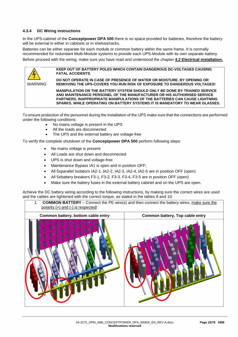
4.3.4 DC Wiring instructions
In the UPS-cabinet of the Conceptpower DPA 500 there is no space provided for batteries, therefore the battery will be external in either in cabinets or in shelves/racks. Batteries can be either separate for each module or common battery within the same frame. It is normally recommended for redundant Multi-Module systems to provide each UPS-Module with its own separate battery. Before proceed with the wiring, make sure you have read and understood the chapter 4.2 Electrical installation.
To ensure protection of the personnel during the installation of the UPS make sure that the connections are performed under the following conditions:
• No mains voltage is present in the UPS • All the loads are disconnected • The UPS and the external battery are voltage-free
To verify the complete shutdown of the Conceptpower DPA 500 perform following steps:
• No mains voltage is present • All Loads are shut down and disconnected • UPS is shut down and voltage-free • Maintenance Bypass IA1 is open and in position OFF; • All 5xparallel Isolators IA2-1, IA2-2, IA2-3, IA2-4, IA2-5 are in position OFF (open) • All 5xbattery breakers F3-1, F3-2, F3-3, F3-4, F3-5 are in position OFF (open) • Make sure the battery fuses in the external battery cabinet and on the UPS are open.
Achieve the DC battery wiring according to the following instructions, by making sure the correct wires are used and the cables are tightened with the correct torque, as stated in the tables 8 and 10:
1. COMMON BATTERY – Connect the PE wire(s) and then connect the battery wires, make sure the polarity (+) and (-) is respected!
Common battery, bottom cable entry Common battery, Top cable entry
WARNING
KEEP OUT OF BATTERY POLES WHICH CONTAIN DANGEROUS DC-VOLTAGES CAUSING FATAL ACCIDENTS.
DO NOT OPERATE IN CASE OF PRESENCE OF WATER OR MOISTURE. BY OPENING OR REMOVING THE UPS-COVERS YOU RUN RISK OF EXPOSURE TO DANGEROUS VOLTAGES!
MANIPULATION ON THE BATTERY SYSTEM SHOULD ONLY BE DONE BY TRAINED SERVICE AND MAINTENANCE PERSONEL OF THE MANUFACTURER OR HIS AUTHORISED SERVICE PARTNERS. INAPPROPRIATE MANIPULATIONS OF THE BATTERIES CAN CAUSE LIGHTNING SPARKS. WHILE OPERATING ON BATTERY SYSTEMS IT IS MANDATORY TO WEAR GLASSES.

04-3275_OPM_ABB_CONCEPTPOWER_DPA_500kW_EN_REV-A.docx Page 23/78 ABB
Modifications reserved
2. SEPARATE BATTERY - Connect the PE wire(s) and then connect the battery wires for each module by making sure the polarity (+) and (-) is respected! It’s is not important which module you start wiring first. Important is to keep clearance for the Filter PCB (shown in the figures below). Accessing to the filter PCB after the UPS installation is important for the service technicians to measure the voltages safely.
Battery PE connection - bottom cable entry Battery PE connection - top cable entry
Separate battery, bottom cable entry Separate battery, Top cable entry
Filter PCB
Filter PCB
04-3275_OPM_ABB_CONCEPTPOWER_DPA_500kW_EN_REV-A.docx Page 24/78 ABB
Modifications reserved
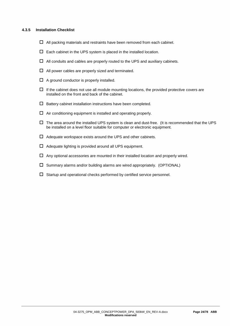
4.3.5 Installation Checklist
All packing materials and restraints have been removed from each cabinet.
Each cabinet in the UPS system is placed in the installed location.
All conduits and cables are properly routed to the UPS and auxiliary cabinets.
All power cables are properly sized and terminated.
A ground conductor is properly installed.
If the cabinet does not use all module mounting locations, the provided protective covers are installed on the front and back of the cabinet.
Battery cabinet installation instructions have been completed.
Air conditioning equipment is installed and operating properly.
The area around the installed UPS system is clean and dust-free. (It is recommended that the UPS be installed on a level floor suitable for computer or electronic equipment.
Adequate workspace exists around the UPS and other cabinets.
Adequate lighting is provided around all UPS equipment.
Any optional accessories are mounted in their installed location and properly wired.
Summary alarms and/or building alarms are wired appropriately. (OPTIONAL)
Startup and operational checks performed by certified service personnel.
04-3275_OPM_ABB_CONCEPTPOWER_DPA_500kW_EN_REV-A.docx Page 25/78 ABB
Modifications reserved
4.4 FRONT VIEW
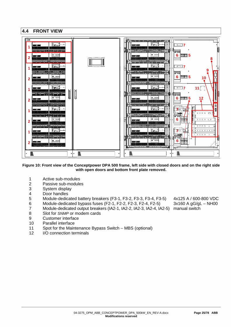
Figure 10: Front view of the Conceptpower DPA 500 frame, left side with closed doors and on the right side with open doors and bottom front plate removed.
1 Active sub-modules 2 Passive sub-modules 3 System display 4 Door handles 5 Module-dedicated battery breakers (F3-1, F3-2, F3-3, F3-4, F3-5) 4x125 A / 600-800 VDC 6 Module-dedicated bypass fuses (F2-1, F2-2, F2-3, F2-4, F2-5) 3x160 A gG/gL – NH00 7 Module-dedicated output breakers (IA2-1, IA2-2, IA2-3, IA2-4, IA2-5) manual switch 8 Slot for SNMP or modem cards 9 Customer interface 10 Parallel interface 11 Spot for the Maintenance Bypass Switch – MBS (optional) 12 I/O connection terminals
1
2
1
2
1
2
1
2
1
2
7
6 5
7
6 5
7
6 5
11
8
9
10
12
6
6
7
7

04-3275_OPM_ABB_CONCEPTPOWER_DPA_500kW_EN_REV-A.docx Page 26/78 ABB
Modifications reserved
5 CONNECTIVITY
5.1 INTERFACING Each UPS cabinet is provided with customer interface ports (also called communication ports) which provides information about the UPS (single units) or the UPS system (parallel system).
The customer interface is composed by (see also the figure 12 at the end of this section):
• Slot for optional Modem card • Slot for optional SNMP card • PC / laptop connection JD1 (RS232 Sub D9/female) or USB • Status LED’s 1 red LED and 1 green LED • Graphical display connection JR3 (RJ 45) • Multidrop configuration SW2 (DIP-SWITCH) • Multidrop connection JR2 (RJ 45) • UPS inputs X3 (Phoenix terminals) • 12VDC source X3 5/6 (Phoenix terminals) • UPS outputs, dry ports X2 (Phoenix terminals) • Interlock Function X1 1/2 (Phoenix terminals) • Multi-Cabinet Configuration SW1-6 (DIP-SWITCH) • Parallel BUS connector JD8 (Sub D25/female)
5.1.1 SMART PORT JD1 on each frame (Serial RS 232 / Sub D9 / male)
The SMART PORT JD1 located on the customer interface board (see figure 10 above, detail 9) RS 232 serial port that allows the UPS Module to be connected to a computer. The connector is a standard D-Type, 9-pin, male. When installed the optional SMART PORT, the software WAVEMON allows the computer to monitor the mains voltage and the UPS status continuously.
In the event of any changes the computer terminal will display a message. (For details see our Monitoring Package: WAVEMON ).
The figure 11 shows how to connect a PC to the UPS with different Sub-D connectors.
Interface Cable (UPS End) Interface cable (Computer End) (9-Pin, D-Type Male) (9-Pin, D-Type Female)
Connects to UPS Connects to JD1 Computer
Figure 11: Connector Cable - PC Serial Port with 9-Pin Connection
1 2 3
9
. .
5
1 2 3
9
. .
5

04-3275_OPM_ABB_CONCEPTPOWER_DPA_500kW_EN_REV-A.docx Page 27/78 ABB
Modifications reserved
5.1.2 Customer interface and DRY PORTs (volt-free contacts)
All Terminals X1-X3 can hold Cable from 0.2mm2 – 1.5mm2 X1 is a 230VAC output which allows to interface with a interlock system. All X2 are potential free contacts and are rated: Max 250Vac/8A; 30Vdc/8A; 220Vdc/0.12A All X3 (except X3 5/6 which is a 12VDC source) are inputs, cable max. R 50Ω at 20mA
Block Terminal Contact Signal On Display Function
X3
X3 / 14 GND
IN
GND - Battery Temperature (only the optional battery sensor from ABB is compatible) X3 / 13 +3.3VDC -
X3 / 12 GND
IN
GND GENERATOR_ OPER_ON
Generator Operation (N.O.) Min. contact load 12V / 1mA X3 / 11 +12Vdc
X3 / 10 GND
IN
GND PARRALEL_SW_OPEN PARRALEL_SW_CLOSE
External Output Breaker (N.O.) Min. contact load 12V / 20mA. X3 / 9 +12Vdc
X3 / 8 GND
IN
GND EXT_MAN_BYP External Manual Bypass (Ext. IA1)
(N.O.) Min. contact load 20mA X3 / 7 +12Vdc
X3 / 6 12V
GND
+12Vdc - + 12 VDC source (UPS protected) (Max. 200mA) X3 / 5 GND -
X3 / 4 GND
IN
GND REMOTE_
SHUTDOWN-
RSD (Remote Shut down) Default setting: disabled. Possibility to enable and set NO or NC via NewSet. X3 / 3 +12Vdc
X3 / 2 C
NO
- REMOTE_
SHUTDOWN-
RSD (Remote Shut down ) for external switch Max. 250Vac/8A ;30Vdc/8A ;110Vdc/0.3A ;220Vdc/0.12A
X3 / 1 -
X2
X2 / 18 CNCNO
- - Common X2 / 17 - - Relais AUX
(function on request, to be defined) X2 / 16 - -
X2 / 15 CNCNO
COMMON_ALARM Common X2 / 14 ALARM No Alarm Condition X2 / 13 Common Alarm (System) X2 / 12 C
NCNO
LOAD_ON_MAINS Common X2 / 11 Message No Load on Bypass X2 / 10 Load On Bypass (Mains) X2 / 9 C
NCNO
BATT_LOW Common X2 / 8 ALARM Battery Ok X2 / 7 Battery Low X2 / 6 C
NCNO
LOAD_ON_INV Common X2 / 5 Message No Load on Inverter X2 / 4 Load on Inverter X2 / 3 C
NCNO
MAINS_OK Common X2 / 2 ALARM Mains Failure
X2 / 1 Mains Present
X1 X1 / 2
2AT
- EXT_MAN_BYP
Interlock Function Max. 30Vdc/2A; 60Vdc/0.7A (Ext Manual Bypass) / 2AT X1 / 1
-
Table 11: Customer Interface Conceptpower DPA 500

04-3275_OPM_ABB_CONCEPTPOWER_DPA_500kW_EN_REV-A.docx Page 28/78 ABB
Modifications reserved
On the Interface board are located two LED’s: • Green LED showing the status of the Interface:
- Fast Blinking: 2 times/sec = Interface is Master (1st Cabinet of a parallel System) - Slow Blinking: 1 times/sec = Interface is Slave ( 2nd,.. 6th cabinet of a //- System)
• Red LED Board Alarm (indicates a possible replacement of the board) On the Master cabinet the following ports of the customer interface board are active:
• The Input ports (X3) • The Output ports (X2) • The Interlock function (X1)
On the Salve cabinet(s) following ports of the customer interface board are active: • The Input ports (X3) • External Output Breaker (X2 9/10) and External Manual Bypass (X2 7/8)
All other ports on the Salve cabinet(s) are inactive. 5.1.3 JD1 / RS232 PC / Laptop Interface
The Computer Interface JD1 located on the distribution part is an intelligent RS 232 serial port that allows the UPS system to be connected to a computer. The connector JD1 is a standard D-Type, 9-pin, female.
It is used to download system event log and to make firmware upgrades.
5.1.4 USB PC / Laptop Interface
The Computer Interface USB has the same function as the RS 232 serial port JD1. Use either USB or RS232 but not both at the same time. 5.1.5 JR2 / RS232 Interface for Multidrop
The Computer Interface JR2 (RJ 45 connector) located on the distribution part is the Multidrop connection which is needed for multi-cabinet configurations. To enable the Multidrop communication between cabinets it is necessary to set JP2 jumper correctly on the customer interface board as shown in the table here below.
Customer Interface Board, PCB NW22085D (with ROM76-12) or NW22085E or later versions
First unit (Master) JP2 = OFF
Middle Unit (Slave) JP2 = ON
Last Unit (Slave) JP2 = ON Note: on the (older) versions NW22085B/C without ROM76-12 make a bridge between X3-11 & X3-12.
5.1.6 Optional feature: Configuration of the External Output Breaker
An External Output Breaker can be connected to each UPS cabinet. Pin 9 and 10 of the phoenix terminal X3 is the input of the UPS for the auxiliary contact of the External Output Breaker. To enable this function it is necessary to set JP8 and JP1-JP5 jumpers correctly on the customer interface board and parallel board of each unit as shown in the two tables here below.
Customer Interface Board, PCB NW22085D (with ROM76-12) or NW22085E or later versions
External Output Breaker disabled (default setting) JP 8 = ON
External Output Breaker enabled JP 8 = OFF
Parallel Board, PCB NW28140D or later versions
External Output Breaker disabled (default setting) JP1-JP2-JP3-JP4-JP5 = ON
External Output Breaker enabled JP1-JP2-JP3-JP4-JP5 = OFF
04-3275_OPM_ABB_CONCEPTPOWER_DPA_500kW_EN_REV-A.docx Page 29/78 ABB
Modifications reserved
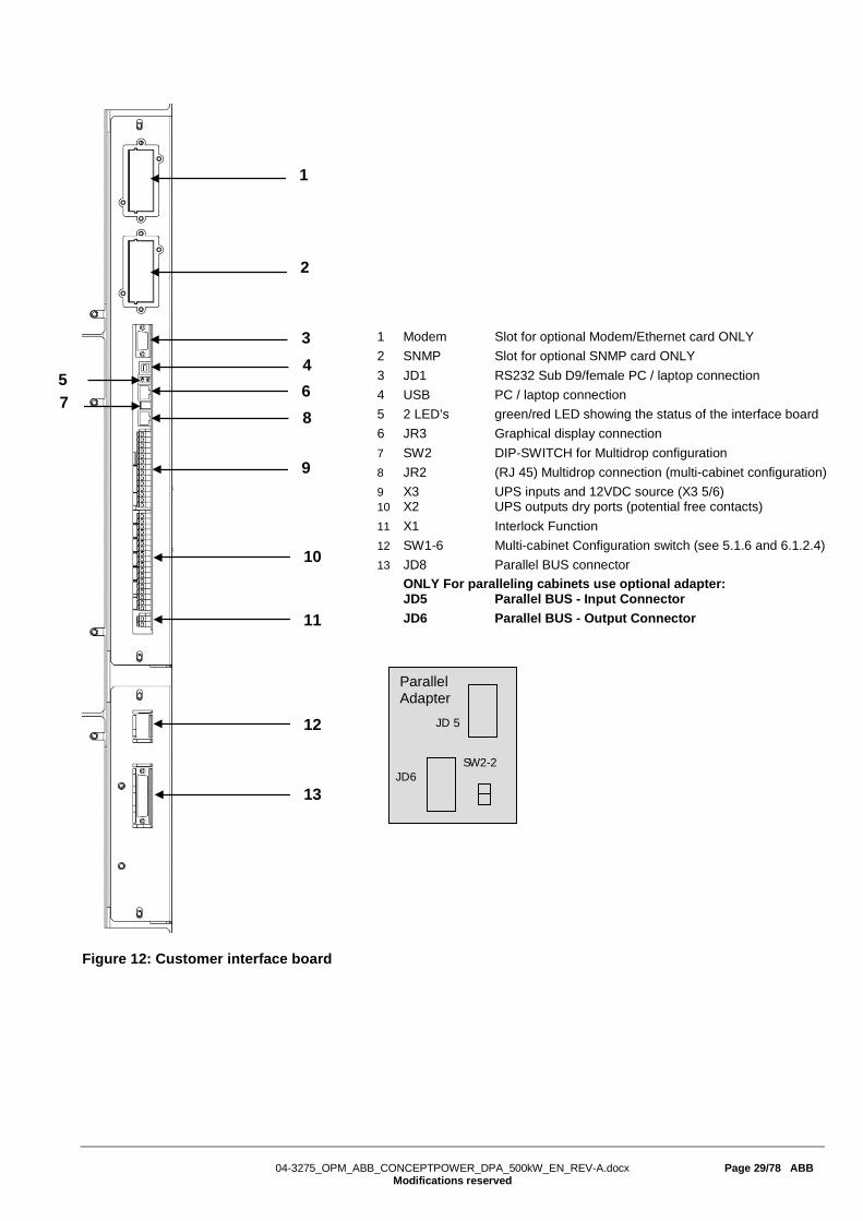
Figure 12: Customer interface board
1
2
3
8
6 4
9
10
11
12
13
5
1 Modem Slot for optional Modem/Ethernet card ONLY 2 SNMP Slot for optional SNMP card ONLY 3 JD1 RS232 Sub D9/female PC / laptop connection 4 USB PC / laptop connection 5 2 LED’s green/red LED showing the status of the interface board 6 JR3 Graphical display connection 7 SW2 DIP-SWITCH for Multidrop configuration 8 JR2 (RJ 45) Multidrop connection (multi-cabinet configuration) 9 X3 UPS inputs and 12VDC source (X3 5/6) 10 X2 UPS outputs dry ports (potential free contacts) 11 X1 Interlock Function 12 SW1-6 Multi-cabinet Configuration switch (see 5.1.6 and 6.1.2.4) 13 JD8 Parallel BUS connector ONLY For paralleling cabinets use optional adapter: JD5 Parallel BUS - Input Connector JD6 Parallel BUS - Output Connector
7
Parallel Adapter JD 5
SW2-2 JD6

04-3275_OPM_ABB_CONCEPTPOWER_DPA_500kW_EN_REV-A.docx Page 30/78 ABB
Modifications reserved
6 OPERATION
6.1 COMMISSIONING The Conceptpower DPA 500 is a high quality electronic UPS, that must be commissioned by a fully trained and certified field service engineer before being put into use.
The commissioning of the UPS involves the connection of the UPS and battery, the checking of the electrical installation and operating environment of the UPS, the controlled start-up and testing of the UPS and customer training.
WARNING!
OPERATIONS ON THE UPS MUST BE PERFORMED BY A SERVICE ENGINEER FROM THE MANUFACTURER OR FROM AN AGENT CERTIFIED BY THE MANUFACTURER.
6.2 MULTI-CABINET CONFIGURATION The CONCEPTPOWER DPA 500 Cabinets may be paralleled for power capacity or for redundancy indefinitely. Every standard CONCEPTPOWER DPA 500 is provided with the parallel option and therefore no time-consuming upgrading is necessary on site.
power connection
parallel cable
Multidrop cable
Figure 13: Multi-Cabinet Configuration
The Multi-Cabinet Chain is based on a decentralized bypass architecture i.e. every UPS is provided with its own static bypass. In a parallel system there is always one Master Module and the other Modules are slaves. If at any time the master is faulty the next UPS (former slave) will immediately take over the master function and the former master will switch off.
Every UPS unit in a parallel configuration is provided with a proper output parallel Isolator (IA2) which, when opened isolates the corresponding unit from the parallel system. Once the parallel isolator (IA2) of a unit is open that unit (module) is isolated from the rest of the parallel system and therefore does not provide power to the output.
For example if you perform the command “LOAD TO BYPASS” on any unit, all the units will transfer the load simultaneously to mains and if you perform the command “LOAD TO INVERTER” on any unit all the UPS’s will simultaneously transfer the load to the inverters.
to the load

04-3275_OPM_ABB_CONCEPTPOWER_DPA_500kW_EN_REV-A.docx Page 31/78 ABB
Modifications reserved
The CONCEPTPOWER DPA TM 500 is paralleled for redundancy (highest availability) or for power parallel systems.
IMPORTANT: The BYPASS MODE (ECO-MODE) function of a parallel systems is the same as in single units of CONCEPTPOWER DPATM 500. If in a parallel UPS system the load is transferred to the BYPASS (load on mains) and if the mains fails, the UPS’s will all be automatically transferred to inverter within 5msec.
6.2.1 Installation Instructions
WARNING!
THE OPERATIONS DESCRIBED IN THIS CHAPTER MUST BE PERFORMED BY A SERVICE ENGINEER FROM THE MANUFACTURER OR FROM AN AGENT CERTIFIED BY THE MANUFACTURER.
NOTE: IN ORDER TO ACHIEVE EQUAL LOAD SHARING BETWEEN THE UPS-CABINETS, THE INPUT CABLE LENGTHS FROM THE INPUT DISTRIBUTION BOARD TO THE UPS AND FROM THE OUTPUT CABLE TO THE OUTPUT DISTRIBUTION BOARD SHOULD BE THE SAME RESPECTIVELY. WHEN CABLING THE UPS’S BEWARE TO CONNECT INPUT AND OUTPUT WIRES TO THE CORRESPONDING TERMINALS, RESPECTING THE SAME PHASE SEQUENCE ON ALL UPS CABINETS. EXAMPLE: PHASE1 OF UPS1 = PHASE1 OF UPS2 = …… = PHASE1 OF UPS n
6.2.2 Paralleling of UPS-Cabinets
For the correct performance of different parallel functions and operations the parallel units communicate continuously between each other. This is achieved by means of the so-called communication BUS-Lines.
After terminating the input and output cabling of each single UPS, it is necessary to connect the units together to form the parallel system. For this purpose a communication BUS line is connected sequentially between the units. Connect communication BUS lines according to Figure 14.
NOTE!
CONNECT THE BUS CABLES ONLY WITH SWITCHED OFF UPS AND OPENED PARALLEL ISOLATORS IA2. RESPECT THE FOLLOWING CONNECTION SEQUENCES.
1. Fit the Parallel Adapter over the Connector JD8 on all UPS-cabinets 2. Set DIP Switch SW2-2 on each Parallel Adapter depending on the UPS Cabinet in the parallel cabinet
configuration (see Figure 15) 3. Connect PORT JD6 on Parallel Adapter of UPS-Cabinet 1and PORT JD5 of Parallel Adapter of UPS-
Cabinet 2 with the corresponding BUS-Cable; 4. Connect PORT JD6 on Parallel Adapter of UPS-Cabinet 2 and PORT JD5 of UPS-Cabinet 3 with the
corresponding BUS-Cable 5. Continue in the same manner for the remaining UPS-Cabinets.
Figure 14: Connection of the Bus Lines when paralleling UPS-Cabinets by means of Parallel Adapters.
!
UPS-Cabinet 1 UPS-Cabinet 2 UPS-Cabinet n-1 UPS-Cabinet n
Parallel Adapter
JD6 JD5 Master-Slave
Input Master-Slave Output SW2-2
Parallel Adapter
JD6 JD5 Master-Slave
Input Master-Slave Output SW2-2
Parallel Adapter
JD6 JD5 Master-Slave
Input Master-Slave Output SW2-2
Parallel Adapter
JD6 JD5 Master-Slave
Input Master-Slave Output SW2-2

04-3275_OPM_ABB_CONCEPTPOWER_DPA_500kW_EN_REV-A.docx Page 32/78 ABB
Modifications reserved
If the UPS-CABINETS are paralleled, the Parallel Adapter will be placed on the Connector JD8 on the distribution panel and the communications cables between the cabinets will be connected through the connectors JD5 and JD6, as we are doing now. NOTE: set the Switch SW2-2 correctly according to the corresponding cabinet configuration.
Figure 15: Parallel Adapter and DIP Switch SW2-2
6.2.3 DIP Switch SW1-6
SW1 1 SW1 2 SW1 3 SW1 4 SW1 5 SW1 6 JP1
First frame OFF OFF OFF OFF OFF ON ON
(See info )
Other frame OFF OFF OFF OFF OFF OFF ON
(See info ) Last frame OFF OFF OFF OFF ON OFF ON
(See info ) Single frame ON ON ON OFF ON ON ON
(See info )
Only 6 Dip switches are mounted on it and the setting for the parallel configuration must be done according to the above table. The Jumper JP1 must be always present (inserted) on all boards inside the parallel
system (single or more frames working in parallel)
The new connector “X1” is used only in case the UPS is equipped with the “synchronization with main” feature. (Available only if a specific “special project” is present on all modules inside the system) In this case the reference “Mains” (phase & neutral) has to be connected to “X1” and the jumpers JP2, JP3 & JP4 mounted inside the board correctly set according to its voltage (See table below)
Mains on X1 JP2 JP3 JP4
480V OFF OFF OFF
230V ON ON OFF
120V ON ON ON
SingleUnit First Unit Middle Unit Last Unit SW 1 ON OFF OFF ON SW 2 ON ON OFF OFF
Parallel Adapter JD 5
SW2-2 JD6
JD8
SW1-6 Dip Switches
6
1

04-3275_OPM_ABB_CONCEPTPOWER_DPA_500kW_EN_REV-A.docx Page 33/78 ABB
Modifications reserved
6.2.4 Multidrop Configuration
Multidrop cable connection
Insert the splitter/s supplied with the installation inside the Multidrop connector/s JR2 on NW22085 on all middle unit/s. Connect the “Previous” end of the multidrop cable on the First Unit and the “Next” end on the second Unit (If more than two unit inside the splitter). Proceed on the same way with all other unit on the installation as shown on the picture.
Board NW22085 Jumper & Switches configuration Verify that the customer interface board (NW22085) of each unit correctly configured according to the following table
JUMPER JP 2 on PCB NW22085D (with ROM76-12) or NW22085E or later versions
First unit OFF
Middle Unit ON
Last Unit ON
Note: on the (older) versions NW22085B/C without ROM76-12 make a bridge between X3-11 & X3-12.
6.2.5 ON/OFF – Main Buttons
The ON/OFF-Buttons serve to shutdown the UPS-system for service or maintenance or for emergency reasons.
NOTE!
WHEN BOTH ON/OFF BUTTONS ON ALL UPS MODULES IN A PARALLEL SYSTEM ARE PUSHED THE POWER SUPPLY TO THE LOAD WILL BE INTERRUPTED.
!
Prev Next
Prev Next
First Unit Middle Unit Last Unit

04-3275_OPM_ABB_CONCEPTPOWER_DPA_500kW_EN_REV-A.docx Page 34/78 ABB
Modifications reserved
6.2.6 Parallel Isolator (IA2)
Every UPS-unit (Means each Module) is provided with a parallel isolator IA2. The parallel isolator is an important element of the UPS-unit, that allows the isolation of a Module from the parallel system without the need to transfer the load to bypass.
NOTE!
IA2 OPEN: THE CORRESPONDING UPS-MODULE IS ISOLATED FROM THE OUTPUT. THERE IS NO COMMUNICATION BETWEEN THE ISOLATED UNIT AND THE REST OF THE PARALLEL SYSTEM. THE ISOLATED UPS-MODULE MAY BE REPLACED WITHOUT COMPROMISING THE REST OF THE SYSTEM. IA2 CLOSED: THE CORRESPONDING UPS IS BEING ADDED TO THE REST OF THE PARALLEL SYSTEM. IMPORTANT: BEFORE CLOSING THE IA2 OF A UPS-MODULE BE SURE THAT THE STATUS OF THAT UPS-MODULE IS THE SAME AS OF THE REST OF THE OPERATING UPS-MODULE WITH CLOSED IA2. EXAMPLE: IF ALL UPS’S WITH CLOSED IA2 ARE ON INVERTER, MAKE SURE THAT THE UNIT ON WHICH ISOLATOR IA2 IS BEING CLOSED IS ALSO ON INVERTER.
6.2.7 Maintenance Bypass (IA1)
There are two types of Parallel System Configurations: redundant and capacity parallel systems
• Redundant Parallel Configuration In a redundant parallel system a UPS-module may easily be isolated from the parallel system by opening the respective isolator (IA2). It is now possible to operate or shut down this unit without influencing the rest of the parallel system. The rest of the parallel system will continue to protect the load. The isolated UPS-Module may be replaced without the need of transferring the load to bypass by means of the Maintenance Bypass (IA1).
• Capacity Parallel Configuration In the event of a fault in one of the UPS-Modules in a capacity parallel system the load will automatically be transferred to static bypass (mains). In order to replace the faulty module the load must be transferred to mains by means of Maintenance Bypass (IA1).
6.2.8 ECO-MODE (BYPASS MODE) in Parallel Systems
The Eco-Mode function in a Parallel System is the same as in Single Systems. If in a CONCEPTPOWER DPA 500 Parallel System the load is supplied by the mains(load on mains) and in the event of mains failure, all UPS’s will automatically transfer the load back to the inverters with 5msec.
In order to provide the load with maximum protection the manufacturer always recommends that the load be supplied by the inverter (ON-LINE-Mode).
!
!

04-3275_OPM_ABB_CONCEPTPOWER_DPA_500kW_EN_REV-A.docx Page 35/78 ABB
Modifications reserved
6.3 COMMISSIONING OF MULTI-CABINET CONFIGURATION
WARNING!
THE OPERATIONS DESCRIBED IN THIS CHAPTER MUST BE PERFORMED BY A SERVICE ENGINEER FROM THE MANUFACTURER OR FROM AN AGENT CERTIFIED BY THE MANUFACTURER.
6.3.1 Start-up of a Multi-Cabinet Configuration
Before starting up a Multi-Cabinet Configuration verify that: 1. All the input and output cabling has been performed correctly according to section 4.3 of this User Manual; 2. The parallel communication cables have been connected correctly according to Paragraph 1.2.2 3. All the DIP Switches for the Modules and CONCEPTPOWER DPATM - Cabinets been set correctly
according to Paragraph 1.2.3 4. All the internal (if any) and /or external battery cabinets/racks have been connected correctly
Start the system as described subsection 6.7 6.3.2 Shutdown of Multi-Cabinet Configuration
Before shutting-down of a Multi-Cabinet Configuration make sure that the loads do need power protection and that they are disconnected.
The UPS may be shut down completely if the loads do not need any power supply. Therefore the steps in this Paragraph are to be performed only after the load has been disconnected and does not need any power supply.
To perform a complete shutdown of a Multi-Cabinet Configuration proceed as described in the shutdown procedure described in section 6.8
6.4 SYSTEM DISPLAY
WARNING!
ONLY PERSONS WHICH HAVE BEEN TRAINED BY SERVICE TECHNICIANS OF THE MANUFACTURER OR HIS CERTIFIED SERVICE PARTNERS ARE ALLOWED TO OPERATE ON THE CONTROL PANEL WITH CLOSED DOORS. ALL OTHER INTERVENTIONS ON THE UPS SYSTEM HAVE TO BE DONE ONLY BY SERVICE TECHNICIANS OF THE MANUFACTURER.
The user-friendly, touchscreen graphical display on the system level offers the opportunity of directly monitoring the system status as well as the status of each individual module. The graphical display additionally provides all the measurements (module and system level) and the user is able to transfer from INVERTER to BYPASS and vice-versa. All other commands must be performed on the DPA display. With both displays in place (module and system level), the UPS offers full user friendliness without making compromises on robustness.
Figure 16: System display
!

04-3275_OPM_ABB_CONCEPTPOWER_DPA_500kW_EN_REV-A.docx Page 36/78 ABB
Modifications reserved
6.4.1 Graphical display operation
For simple operation and configuration, the UPS is optionally delivered with a microprocessor-based touchscreen display. The navigation, procedures and the features of the display are detailed in subsequent sections. The touchscreen display enables the operator to perform the following:
• Check operational status and measurements • Execute operational commands • Monitor the power flow through the UPS system • Check events and alarm history • Silence alarms • Adjust programmable parameters • Check the status of the batteries
6.4.2 Rear View
NOTE!
PLEASE NOTE THAT THE EMERGENCY SHUTDOWN FUNCTION BY PRESSING THE BUTTONS ON/OFF 1 + ON/OFF 2 IS DISABLED.
Figure 17: Rear view
!

04-3275_OPM_ABB_CONCEPTPOWER_DPA_500kW_EN_REV-A.docx Page 37/78 ABB
Modifications reserved
I/O PORTS
SD Card Slot for the SD card
USB USB connector
DC Input Power supply connector (only needed if the RJ-45 cable is >75 & <100m)
UPS Input RJ-45 connector
LED’s
UPS Status GREEN: when the UPS is on inverter mode RED: when the inverter is on alarm
Alarm OFF: if no alarm present RED: if unread alarm(s) present
BUTTONS
Reset Press the “Reset” button to reset the remote panel
ON/OFF 1/2 Press “ON/OFF 1” + “ON/OFF 2”: Function disabled Press “Reset” + “ON/OFF 1” buttons simultaneously, then release "Reset" and hold the "ON/OFF 1" button for 10 seconds: Touch screen calibration
6.4.3 Start up and installation
When the UPS is energized, the display is automatically turned on. It is initiated for a few seconds and subsequently the user is directed to the mimic diagram screen. 6.4.4 Navigation
A few icons and some information are displayed in the top of every screen as indicated in the Figure 17.
Figure 18: Display header
A Home Directs the user to the navigation screen.
B Mimic diagram Directs the user to the mimic diagram screen.
C Warning symbol Warning symbol: Appears in case of alarms or events. Touching this icon the alarm is silenced and the events screen is displayed.
D Date Adjustable in the user menu.
E Time Adjustable in the user menu.
F Module selection Directs the user to the module selection screen from where it is possible to select the module and start the navigation (status and measurements) on module level.
G System status Status of the load
System status: indicates that the user is in the system level navigation. Status of the load indicates if the load is protected, when the user is in the module level.
H UPS number
The numbering after the symbol „P” is sequential and represents each module or frame in the system. For eg. “P01” indicates the UPS number 01 in a parallel system. This information can be configured by a service technician.
G H
A B C D E F

04-3275_OPM_ABB_CONCEPTPOWER_DPA_500kW_EN_REV-A.docx Page 38/78 ABB
Modifications reserved
Defining the UPS positioning in a system:
The position of each UPS within a system has to be configured not only in the graphical interface but also in the hardware. The position is determined as one of the following:
• “First” UPS in the parallel configuration • “Middle” UPS in the parallel configuration (there may be more than one) • “Last” UPS in the parallel configuration. The maximum number of parallel cabinets is six (6). The maximum
number of parallel modules is thirty (30). In a multi-cabinet configuration chain, the cabinet is seen as “First” and “Last” in an imaginary chain. Configure the DIP switch for the existing system. For more details concerning the positions of this DIP switch, refer to Chapter 6.2.3. 6.4.5 Mimic Diagram – system level
The mimic diagram is the default screen. It shows the power flow through the UPS system (single frame as well as multi-cabinet configuration) and indicates its status. This diagram can be accessed from any screen using the corresponding icon in the display header.
Figure 19: Mimic Diagram Screen - system level
The color of each block identify its functional status. There are four main colors in the mimic diagram: • Green: In operation • White: Inactive block • Yellow: Warning condition • Red: Fault condition
Device Color meaning
Rectifier Green: Rectifier is on. Red: Rectifier is switched off.
Inverter Green: Load is on inverter. Red: Inverter is switched off.
Bypass Green: Load is on bypass or eco-mode White: Bypass is switched off.
Battery
Green: Battery is charging or discharging. Yellow:: Battery is not charging nor discharging. Red: Battery is in fault condition or is discharged.
Arrows indicate if battery is charging or discharging.
Maintenance Bypass IA1 Yellow: Load is on maintenance bypass White: Maintenance bypass opened
Output Breaker IA2 Green: Parallel- Output breaker is closed (Position ON)
(Default condition with single UPS) White: Parallel- Output breaker is opened (Position OFF)

04-3275_OPM_ABB_CONCEPTPOWER_DPA_500kW_EN_REV-A.docx Page 39/78 ABB
Modifications reserved
Touching the functional blocks in the mimic diagram, the measurements related to the object selected are displayed. The interactive blocks are the following:
• Rectifier • Inverter • Battery • Bypass • Load
The green connecting lines indicate the power flow in the system. 6.4.6 Module selection screen
By pressing the button F (see 6.4.4 Navigation ) directs the user to the module selection screen from where it is possible to select the module and start the navigation (status and measurements) on module level. The module selection screen will show the amount of module in the system show the status of each module as follows:
• Black: module in operation • White: inactive module / switched off • Red: module with general alarm
Example with 5 modules all in operation. Example with 20 modules all in operation.
Example with 5 modules, 01-03 in operation, 04 inactive and 05 with general alarm. Example with 30 modules all in operation.
By touching on one of the icons the user gets to the mimic diagram and form there the navigation gives the same possibility but on the module level.

04-3275_OPM_ABB_CONCEPTPOWER_DPA_500kW_EN_REV-A.docx Page 40/78 ABB
Modifications reserved
6.4.7 Home screen
The display is driven by a menu-prompted software. The home screen is accessible from any screen and gives access to the following:
Events: Stores and displays the last events occurred in chronological order; Measures: Displays electrical measurements of the UPS such as voltages, power, frequencies, currents,
autonomy, etc; Command: Enables the operator to execute the following basic operations: “Load to inverter”, “Load to bypass”
and “Clear all alarms”. Once a command is executed the user is immediately re-directed to the mimic diagram screen.
UPS Data: Gives information regarding the identity of the UPS; User: Enables the adjustment of data such as date and time, automatic battery test, etc; Service: Enables the service technician to adjust several UPS parameters
Figure 20: Home Screen Events Displays a list of recently occurred events with date, time, event name, description and sequential identification number. It is possible to order the events and as default the most recent appears on top. Measures This item displays the full set of measurements for each functional block of the UPS: rectifier, bypass, inverter and load. It also displays the battery parameters such as temperature, cell voltage, current, capacity and run time.
04-3275_OPM_ABB_CONCEPTPOWER_DPA_500kW_EN_REV-A.docx Page 41/78 ABB
Modifications reserved
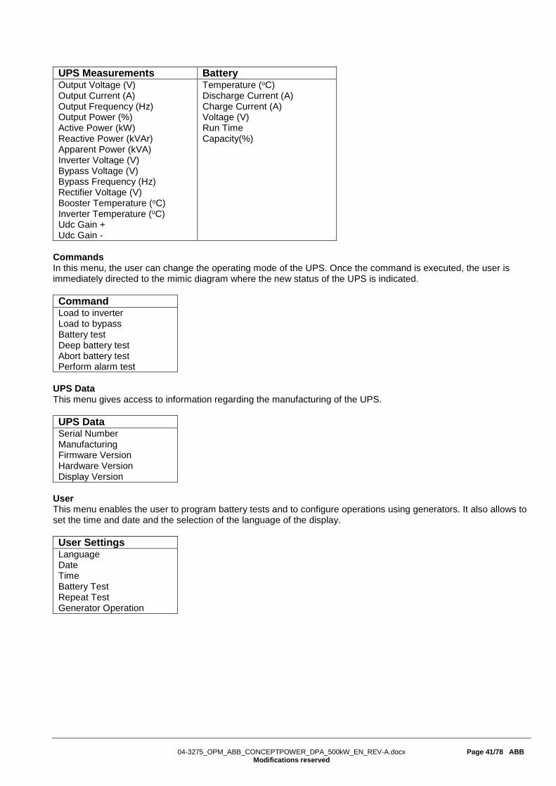
UPS Measurements Battery Output Voltage (V) Output Current (A) Output Frequency (Hz) Output Power (%) Active Power (kW) Reactive Power (kVAr) Apparent Power (kVA) Inverter Voltage (V) Bypass Voltage (V) Bypass Frequency (Hz) Rectifier Voltage (V) Booster Temperature (oC) Inverter Temperature (oC) Udc Gain + Udc Gain -
Temperature (oC) Discharge Current (A) Charge Current (A) Voltage (V) Run Time Capacity(%)
Commands In this menu, the user can change the operating mode of the UPS. Once the command is executed, the user is immediately directed to the mimic diagram where the new status of the UPS is indicated. Command Load to inverter Load to bypass Battery test Deep battery test Abort battery test Perform alarm test
UPS Data This menu gives access to information regarding the manufacturing of the UPS. UPS Data Serial Number Manufacturing Firmware Version Hardware Version Display Version
User This menu enables the user to program battery tests and to configure operations using generators. It also allows to set the time and date and the selection of the language of the display. User Settings Language Date Time Battery Test Repeat Test Generator Operation

04-3275_OPM_ABB_CONCEPTPOWER_DPA_500kW_EN_REV-A.docx Page 42/78 ABB
Modifications reserved
Service This menu is reserved for certified service engineers. It is not to be used by end users and is protected by a password. UPS Measurements Battery Offset UPS Output Voltage (V) Output Current (A) Output Frequency (Hz) Output Power (%) Active Power L1 (kW) Active Power L2 (kW) Active Power L3 (kW) Reactive Power (kVAr) Apparent Power (kVA) Inverter Voltage (V) Bypass Voltage (V) Bypass Frequency (Hz) Rectifier Voltage (V) Rectifier Temperature (oC) Inverter Temperature (oC) Udc Gain + Udc Gain -
Run Time Voltage + (V) Voltage - (V) Charge Current (A) Discharge Current (A) Temperature (oC) I Battery Offset Capacity(%) V Battery Offset + V Battery Offset - Autonomy (min) Type Blocks Cells Floating Voltage (V) Minimum Threshold Common Battery Start Fast Charge Stop Fast Charge
P Load Offset L1 P Load Offset L2 P Load Offset L3 Q Load Offset L1 Q Load Offset L2 Q Load Offset L3 Inverter DC L1 Inverter DC L2 Inverter DC L3 Output DC L1 Output DC L2 Output DC L3 I Inverter Offset L1 I Inverter Offset L2 I Inverter Offset L3 I Bypass Offset L1 I Bypass Offset L2 I Bypass Offset L3 I Battery Offset V Battery Offset + V Battery Offset -
Type Power Unit Number Slot ID Cosphi System Parallel Frequency Sync Window Inverter Voltage (V) Rectifier Voltage (V) General Alarm Delay Converter Separate Bypass
UPS Data Commands Tests Manufacturing Firmware Version Hardware Version Display Version Dynamic Password
Clear Alarms Service Mode Standby Mode Default Config.
Inverter Voltage Open K Bypass Close K Bypass
Upgrading from LCD to graphical interface For substitution of past generations displays, certify that the UPS software version is compatible with the graphical display. If that is not the case, upgrade the system to the newest software version. Then substitute the entire door of the UPS and connect the display using the same connector as for the LCD control panel. All information from the UPS (such as serial number, manufacturing date and version of the software and hardware) will be automatically loaded to the new interface once it is connected to your UPS.

04-3275_OPM_ABB_CONCEPTPOWER_DPA_500kW_EN_REV-A.docx Page 43/78 ABB
Modifications reserved
6.4.8 Operating mode
6.4.8.1 Online mode (Inverter mode) The Online mode is the UPS operating mode in which the load is supplied through the rectifier and the inverter.
Figure 21: Online mode on Mimic Diagram
The Online mode provides the highest degree of protection, especially in the event of a mains disturbance or failure.
This operating mode is always recommended if the critical loads will not tolerate any interruption of the supply (not even the shortest).
In the unlikely event of an inverter fault or overload condition the UPS will transfer the load automatically and without interruption to the static bypass-mains supply (transfer time = 0ms).
6.4.8.2 Eco mode (Offline or bypass mode)
In Eco mode, the load is supplied from the mains through the static bypass.
Figure 22: Eco mode on Mimic Diagram
When the UPS is operating in Eco mode, the efficiency of the system is higher (99%). In the event of a mains failure the load will automatically be transferred from mains to inverter within 5 ms (this is valid for single and parallel systems). The battery charger remains active in Eco mode.
Operating in Eco mode is recommended only if the load can tolerate interruptions of 3-5 ms (transfer time from Eco mode to Online mode).
NOTE! TO HAVE THE MOST ESSENTIAL SECURITY LEVEL, WE RECOMMEND TO RUN THE UPS ON ONLINE OPERATION MODE.
!

04-3275_OPM_ABB_CONCEPTPOWER_DPA_500kW_EN_REV-A.docx Page 44/78 ABB
Modifications reserved
6.4.8.3 Maintenance bypass mode
Before transferring the load to maintenance bypass (IA1) always check that all the UPS-modules are in Eco-Mode (Bypass-Mode).
The Maintenance Bypass mode is performed using the IA1 bypass switch in the front of the UPS:
Switch Position Effect Status
ON
Maintenance bypass switch closed:
(Load supplied directly from mains)
Warning indicates in the display:
“Manual bypass is closed”
OFF Maintenance bypass switch open:
Normal operating condition (Load supplied by inverter)
Warning indicates in the display:
“Manual bypass is opened”
NOTE!
ON MANUAL OR MAINTANENCE BYPASS MODE, THE LOAD IS NOT PROTECTED AGAINST ANY MAINS FAILURES OR MAINS DISTURBANCES.
6.5 MODULE DISPLAY – CONTROL PANEL The user-friendly control panel is composed of three parts: • LCD DISPLAY • MIMIC DIAGRAM (dual color-LED) • BUTTONS • BUZZER (generating a sound when an alarm is active)
Figure 23: Module Control Panel
!

04-3275_OPM_ABB_CONCEPTPOWER_DPA_500kW_EN_REV-A.docx Page 45/78 ABB
Modifications reserved
The 2 x 20 character LCD simplifies the communication with the UPS and provides the necessary monitoring information about the UPS. The menu driven LCD enables the access to the:
• Even register (event log) • Show measurements such as U, I, f, P, Q, S, load %, battery runtime and others • Perform commands like start-up and shut-down of UPS and others • Load transfer from INVERTER to BYPASS and vice-versa • Diagnosis (SERVICE MODE) • Adjustments and testing
6.5.1 LED Indicators
The mimic diagram serves to indicate the general status of the UPS. The LED-indicators show the power flow status and in the event of mains failure or load transfer from inverter to bypass and vice-versa. The corresponding LED-indicators will change colors from green (normal) to red (warning).
The LEDs LINE 1 (rectifier) and LINE 2 (bypass) indicate the availability of the mains power supply.
The LEDs INVERTER and BYPASS if green indicate which of the two is supplying power to the critical load. When the battery is supplying the load due to mains failure the LED-indicator BATTERY is flashing.
The LED-indicator ALARM is a visual indication of any internal or external alarm condition. At the same time an audible alarm will be activated.
INDICATOR INDICATOR STATUS MEANING
ALARM OFF RED
No alarm condition Alarm condition
LINE 1 GREEN RED
Mains rectifier available Mains rectifier not available
LINE 2 GREEN RED OFF
Mains bypass available Main bypass not ok or not available UPS is turned off
BYPASS GREEN OFF
Load on bypass (Bypass-or Eco-Mode) Bypass not operating (switched-off)
INVERTER GREEN RED OFF
Load on inverter Inverter fault or load not transferable to inverter Inverter not operating (switched-off)
BATTERY GREEN RED Flashing RED Flashing GREEN
Battery OK Battery fault or battery is discharged Battery in discharge and battery voltage critical or battery fuse open Battery in discharge and battery voltage good
6.5.2 Buttons
The buttons allow the user to operate the UPS to perform settings and adjustments, to start-up and shutdown the UPS, to monitor on the LCD display the voltages, currents, frequencies and other values.
BUTTON FUNCTION ON/OFF ON/OFF
• By pressing both keys simultaneously it switches the UPS ON • By pressing both keys simultaneously it switches the UPS OFF (shutdown)
UP () • Move upwards through the menu • Increase values
DOWN () • Move downwards through the menu • decrease values
RESET • Cancel the audible alarm. If the alarm condition remains the LED will remain red • Return to previous menu
ENTER • Confirms a chosen menu item • Confirms a chosen value

04-3275_OPM_ABB_CONCEPTPOWER_DPA_500kW_EN_REV-A.docx Page 46/78 ABB
Modifications reserved
6.5.3 ON/OFF Start-up and Shutdown Buttons
NOTE!
IN THE CASE THAT THE PARALLEL UPS SYSTEM HAS TO BE TURNED OFF, THEN BOTH ON/OFF BUTTONS ON ALL UPS MODULES HAVE TO BE PUSHED. IN THIS CASE THE POWER SUPPLY TO THE LOAD WILL BE INTERRUPTED
6.5.4 Definition of a Single/Parallel-Module System
To define a single or parallel UPS the “SET-UP SERVICE” menu, which is password protected, need to be activat
ed using program line 4 “UPS MODEL”. See Service Manual Section E.
6.5.5 Definition of a Single/ Multi-Cabinet Chain (DIP Switch SW1-6)
By means of the DIP Switch SW1-6, which is located on the front of a Cabinet, it is possible to determine the “position” of the Cabinets in Multi-Cabinet Chain:
• “First” in the Multi-Cabinet Chain • “Middle” in the Multi-Cabinet Chain (there may be more than one) • “Last” in the Multi-Cabinet Chain.
NOTE: If a Cabinet is a Single Cabinet then it is seen as the “First” and “Last” in an imaginary Chain. So the positions of the DIP Switch SW1-6 must be set as shown below:
Table 12: DIP Switch SW1-6 6.5.6 Status Screens
DESCRIPTION LCD-DISPLAY 1 Load is protected by UPS power. Load is supplied by
inverter(Normal Operation) and the batteries are connected and o.k.
LOAD PROTECTED
P01
2 Load is not protected by UPS power. Load is supplied by mains power (load on bypass) or it is supplied by the inverter (normal operation) and the batteries are not o.k.
LOAD NOT PROTECTED
P01
3 Load not supplied. UPS is switched off. To start the UPS press the two ON/OFF buttons simultaneously.
LOAD OFF SUPPLY FAILURE
P01
4 The UPS/module is not supplying load anymore. The output switch is open
LOAD DISCONNECTED PARALLEL SWITCH OPEN
P01
SW1-6 Single cabinet
1 ON
2 ON
3 ON
4 OFF
5 ON
6 ON
!

04-3275_OPM_ABB_CONCEPTPOWER_DPA_500kW_EN_REV-A.docx Page 47/78 ABB
Modifications reserved
On the right hand side of the LCD there is a 3-digit indicator defining the UPS “Position” in the Multi-UPS system. S stands for Single UPS. The system consists only of one UPS. P01 stands for Parallel UPS in a Multi- UPS system and 01 stands for the first UPS (MASTER) in the
parallel UPS system. P02 stands for Parallel UPS in a Multi- UPS system and 02 stands for the second UPS (SLAVE) in the
Multi- UPS system. P03 stands for Parallel UPS in a Multi- UPS system and 03 stands for the third UPS (SLAVE) in the
Multi- UPS system.
The definition of the UPS “Position” in a parallel system is achieved in the Menu Set-Up Service. DESCRIPTION LCD-DISPLAY Single UPS Systems SYSTEM CONFIGURATION
SINGLE S
Parallel System e.g. first UPS cabinet SYSTEM CONFIGURATION PARALLEL
P01
Parallel System e.g. second UPS cabinet / Slave LOAD OFF SUPPLY FAILURE
P02
Note: The max no. of UPS units is 6. 6.5.7 Main Menu Screen
DESCRIPTION LCD-DISPLAY 1 Logging Control. A log of the last 99 events is stored in the
Power Management Display. EVENT LOG MEASUREMENTS
2 In Menu Measurements: monitor voltages, power, frequencies, currents, autonomy etc.
MEASUREMENTS COMMANDS
3 The Command Menu enables to perform the commands “Load to inverter”, Load to bypass, battery test.
COMMANDS UPS DATA
4 The UPS Data are the UPS personalized information “serial number”
UPS DATA SET-UP USER
5 Various settings can be performed by the user: Date/Time, automatic battery test, etc.
SET-UP USER SET-UP SERVICE
6 Various adjustments can be performed by the service staff SET-UP SERVICE NO MORE MENU
6.5.8 Event Log Screen
DESCRIPTION LCD-DISPLAY 1 Logging Control; a log of the last 99 events is stored in the
Power Management Display. 01 05-10-08 LOCAL LOAD OFF
14:38:59
2 Every stored event is identified with a sequential number and time stamp.
02 05-10-08 LOCAL LOAD TO BYP
14:38:56
3 By press ENTER the code of the event will be displayed. (Press ENTER to come back to the previous indication)
03 8104 LOCAL LOAD TO INV
4 All events and alarms are indicated with their date and time of appearance.
04 05-10-08 LOCAL LOAD TO INV
14:37:14
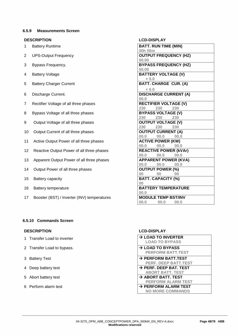
04-3275_OPM_ABB_CONCEPTPOWER_DPA_500kW_EN_REV-A.docx Page 48/78 ABB
Modifications reserved
6.5.9 Measurements Screen
DESCRIPTION LCD-DISPLAY 1 Battery Runtime BATT. RUN TIME (MIN)
00h 00m 2 UPS-Output Frequency OUTPUT FREQUENCY (HZ)
50.00 3 Bypass Frequency. BYPASS FREQUENCY (HZ)
50.00 4 Battery Voltage BATTERY VOLTAGE (V)
+ 0.0 5 Battery Charger Current BATT. CHARGE CUR. (A)
+ 0.0 6 Discharge Current. DISCHARGE CURRENT (A)
00.0 7 Rectifier Voltage of all three phases RECTIFIER VOLTAGE (V)
230 230 230 8 Bypass Voltage of all three phases BYPASS VOLTAGE (V)
230 230 230 9 Output Voltage of all three phases OUTPUT VOLTAGE (V)
230 230 230 10 Output Current of all three phases OUTPUT CURRENT (A)
00.0 00.0 00.0 11 Active Output Power of all three phases ACTIVE POWER (KW)
00.0 00.0 00.0 12 Reactive Output Power of all three phases REACTIVE POWER (kVAr)
00.0 00.0 00.0 13 Apparent Output Power of all three phases APPARENT POWER (KVA)
00.0 00.0 00.0 14 Output Power of all three phases OUTPUT POWER (%)
00 00 00 15 Battery capacity BATT. CAPACITY (%)
00 16 Battery temperature BATTERY TEMPERATURE
00.0 17 Booster (BST) / Inverter (INV) temperatures MODULE TEMP BST/INV
00.0 00.0 00.0 6.5.10 Commands Screen
DESCRIPTION LCD-DISPLAY
1 Transfer Load to inverter LOAD TO INVERTER LOAD TO BYPASS
2 Transfer Load to bypass. LOAD TO BYPASS PERFORM BATT.TEST
3 Battery Test
PERFORM BATT.TEST PERF. DEEP BATT.TEST
4 Deep battery test PERF. DEEP BAT. TEST ABORT BATT. TEST
5 Abort battery test ABORT BATT. TEST PERFORM ALARM TEST
6 Perform alarm test PERFORM ALARM TEST NO MORE COMMANDS

04-3275_OPM_ABB_CONCEPTPOWER_DPA_500kW_EN_REV-A.docx Page 49/78 ABB
Modifications reserved
6.5.11 UPS Data
DESCRIPTION LCD-DISPLAY
1 These general UPS Data are set by the manufacturer. UPS SERIAL NUMBER PWA nnnnnn
2 Manufacturing date DATE OF MANUFACTURE 15/01/2014
3 EPROM Version EPROM VERSION V.V CCCC
4 Hardware Version HARDWARE VERSION 00000000
5 Dynamic password DYNAMIC PASSWORD YES/NO
6 Actual Date and Time DATE TIME dd-mm-yyyy hh:mm:ss
6.5.12 Set-Up User
DESCRIPTION LCD-DISPLAY
1 Set-up Language
SET LANGUAGE SET DATE AND TIME
2 Set-up Date and Time SET DATE AND TIME SET-UP BATT. TEST
DD/MM/YY HH:MM:SS
3 Set-up battery test SET BATTERY TEST SET GENERATOR OP.
DAY OF MONTH (1-31)
HOUR OF DAY (1-24)
REPETITIVE (Y/N) YES/NO
4 Set-up operation with Gen-Set SET GENERATOR OP. NO MORE SETTINGS
BATT.CHARGE LOCK YES/NO
BYPASS LOCK YES/NO
6.5.13 Set-Up Service
DESCRIPTION LCD-DISPLAY
1 This Menu is reserved for CERTIFIED service engineers. It is not to be used by End-Users
SET-UP SERVICE PASSWORD
2 Type in password PASSWORD.
Note: Password is required to enter into the service menu.

04-3275_OPM_ABB_CONCEPTPOWER_DPA_500kW_EN_REV-A.docx Page 50/78 ABB
Modifications reserved
6.6 OPERATING MODES 6.6.1 Mode "ON LINE" (INVERTER MODE)
The ON-LINE-Mode is the UPS-Operating Mode in which the load is supplied through the RECTIFIER and INVERTER.
Using the control panel the UPS can easily be transferred to the ON-LINE-Mode. The ON-LINE-Mode provides the highest degree of protection, especially in the event of a mains disturbance or failure. This operating mode is always recommended if the critical loads (computer systems) will not tolerate any interruption of the supply (not even the shortest). In the unlikely event of an inverter fault or overload condition the UPS will transfer the load automatically and without interruption to the static bypass-mains supply (transfer time = 0).
6.6.2 Mode"OFF-LINE"(ECO- or BYPASS MODE)
In the "OFF-Line Mode”, the load is supplied from the mains through the static bypass. Using the control panel the UPS may be easily transferred to "Bypass Mode”.
When the UPS is operating in "Bypass Mode”, the efficiency of the system is higher. In the event of a mains failure the load will automatically be transferred from mains to inverter within 5 msec (this is valid for single and parallel systems). The battery charger remains active in the "Bypass-Mode”.
The "Bypass-Mode”, is recommended only if the loads can tolerate interruptions of 3-5 ms (transfer time from Bypass Mode to ON-LINE Mode).
NOTE! TO HAVE THE MOST ESSENTIAL SECURITY LEVEL, WE RECOMMEND TO RUN THE UPS ON NORMAL OPERATION MODE, MEANS ON-LINE MODE.
6.6.3 "MAINTENANCE BYPASS" - Mode
Before transferring the load to Maintenance Bypass (IA1) always make sure all the UPS-modules are in the "Bypass-Mode” or “ECO-Mode”. The Maintenance Bypass mode is performed by closing (put in position ON) the IA1 Maintenance Bypass switch on the front of the UPS.
!
LED Indicator Color LINE 1 Green LINE 2 Green BYPASS OFF INVERTER Green BATTERY Green
LED Indicator Color LINE 1 Green LINE 2 Green BYPASS Green INVERTER OFF BATTERY Green

04-3275_OPM_ABB_CONCEPTPOWER_DPA_500kW_EN_REV-A.docx Page 51/78 ABB
Modifications reserved
POSITION OF IA1 EFFECT
ON Bypass-Switch Closed (Load supplied directly from mains) LCD-indication: “MANUAL BYP IS CLOSED” LED Indicators will indicate as shown in table below.
OFF Bypass-Switch Open – Normal operating condition (Load supplied by inverter) LCD-indication “MANUAL BYP IS OPEN” LED Indicators will indicate as shown in table below.
Bypass Switch LED Indicator ON OFF LINE 1 Green Green LINE 2 Green Green BYPASS Green OFF INVERTER RED Green BATTERY Green Green
NOTE!
ON OPERATION MODE “MANUAL BYPASS“ THE LOAD IS NOT PROTECTED AGAINST ANY MAINS FAILURES OR MAINS DISTURBANCES.
6.6.4 Output Switch/Parallel Isolator (IA2)
Every UPS-unit is provided with an output parallel isolator (IA2) which, when opened isolates the corresponding unit from the PARALLEL BUS and from the LOAD. Once IA2 is open there is no power on the load coming from the UPS.
In redundant parallel configurations it is used to isolate a unit from the parallel system without the need of transferring the load to bypass.
POSITION EFFECT
ON Normal Operation (Load supplied by UPS)
OFF UPS isolated from Parallel Bus for maintenance or UPS replacement (UPS not supplying load)
!
MAINS LOAD
MAINTENANCE BYPASS
UPS

04-3275_OPM_ABB_CONCEPTPOWER_DPA_500kW_EN_REV-A.docx Page 52/78 ABB
Modifications reserved
6.7 START-UP PROCEDURE
WARNING!
THE OPERATIONS DESCRIBED IN THIS CHAPTER MUST BE PERFORMED BY A SERVICE ENGINEER FROM THE MANUFACTURER OR FROM AN AGENT CERTIFIED BY THE MANUFACTURER.
Situation of UPS-System before switching it on:
1. Make sure the fuses for the supply of UPS-System in the Input Distribution Board on site are open. 2. Make sure all the input and output cabling has been performed correctly and check the input phase
rotation. 3. Verify that all Parallel Isolator Switches IA2-1, IA2-2, IA2-3, IA2-4, IA2-5 are all open (Position OFF). 4. Verify that the Maintenance Switch IA1 (if present) is open and in Position OFF. 5. Make sure all the battery breakers (F3-1, F3-2, F3-3, F3-4, F3-5) in the UPS (if any) and the external
battery cabinets are open. 6. Check the Position of the DIP Switches SW1-6. This is a Single-Cabinet Configuration, and the DIP
Switches SW1-6 must be set according to positions shown in section 6.2.3.
Start up procedure of Conceptpower DPA 500:
1. Insert fuses for the supply of UPS-System in the Input Distribution - The LED-indicators LINE 1 and battery on UPS-Module is lit – green - On LCD-Display “LOAD OFF, SUPPLY FAILURE” will appear.
2. UPS-Module 1: Press both “ON/OFF” Main Buttons to switch on UPS. LCD panel must display: “LOAD DISCONNECTED PARALLEL SWITCH OPEN” and the LED-indicator will appear as shown below:
LED Indicator Colour LINE 1 Green LINE 2 Green BYPASS Green INVERTER OFF BATTERY Flashing Green
3. Check Command: LOAD TO INVERTER LED indicator will appear as shown below:
LED Indicator Colour LINE 1 Green LINE 2 Green BYPASS OFF INVERTER Green BATTERY Flashing Green
4. Scroll through the menu measurement and check their correctness
5. Modules 2-5: Repeat same procedure as for Module 1:Steps 2)-4).
6. Check battery polarity and voltage.
7. If the battery polarity and voltage is correct insert internal (if any) and external battery fuses (breakers).
8. Testing of Parallel Functions (The load fuses in output Distribution Board are still open i.e. the loads are disconnected!). All UPS-Modules are on INVETER MODE
9. Press simultaneously the two ON/OFF buttons on the UPS-control panel (PMD) on all control panels to turn the modules OFF. On the LCD’s message “LOAD OFF, SUPPLY FAILURE” will appear

04-3275_OPM_ABB_CONCEPTPOWER_DPA_500kW_EN_REV-A.docx Page 53/78 ABB
Modifications reserved
10. Close Parallel Isolator IA2-1 (position ON) of Module 1, on LCD: “PARALLEL SW CLOSED” will appear. Repeat the same for all other modules.
11. Press simultaneously the two ON/OFF buttons on the UPS-control panel (PMD) on all control panels to turn the modules ON. On output Terminal Block there is now UPS power and on all LCD’s: “LOAD PROTECTED” will appear.
12. Load transfer to Maintenance Bypass Go to Menu COMMANDS and choose command “LOAD TO BYPASS” and transfer the load to mains on control panel of any one of the UPS-modules. Close Maintenance Bypass Switch IA1 (position ON) On LCD: “MANUAL BYP IS CLOSED” will appear and the LED-indicator will indicate as shown below:
LED Indicator Colour LINE 1 Green LINE 2 Green BYPASS Green INVERTER RED BATTERY Green
13. Connect Load to the UPS Output Insert fuses in output Distribution Board. Verify on control Panel that the load is on bypass.
14. Open Maintenance Bypass Switch IA1 On LCD: “MANUAL BYP IS OPEN” will appear followed by “LOAD NOT PROTECTED”
15. Check on LCD the Output Powers, Voltages Currents and Frequencies.
16. Load transfer to Inverter Go to Menu COMMANDS and choose command “LOAD TO INVERTER” and transfer the load to inverter on control panel of any one of the UPS-modules. On all LCD’s: “LOAD PROTECTED” will appear.
17. Check the output Voltages and Currents once again.
THE LOAD IS NOW PROTECTED BY THE CONCEPTPOWER DPA 500

04-3275_OPM_ABB_CONCEPTPOWER_DPA_500kW_EN_REV-A.docx Page 54/78 ABB
Modifications reserved
6.8 SHUTDOWN PROCEDURE
WARNING!
THE OPERATIONS DESCRIBED IN THIS CHAPTER MUST BE PERFORMED BY A SERVICE ENGINEER FROM THE MANUFACTURER OR FROM AN AGENT CERTIFIED BY THE MANUFACTURER.
The CONCEPTPOWER DPA 500 may be shutdown completely, if the load does not need input power for an extended period of time.It may be switched to Maintenance Bypass Mode for service or maintenance purposes, or transferred to the OFF-LINE Mode (ECO-Mode), if the load does not need the highest degree of protection. The load may be disconnected by means of the two ON/OFF (LOAD-OFF) buttons for security reasons.
Complete Shutdown procedure of CONCEPTPOWER DPA 500
Only in case there is no need to supply the load, the UPS System can be completely shut down. The following procedures can only be executed after the load has completely been de-energized.
NOTE!
IN THE CASE THAT THE PARALLEL UPS SYSTEM HAS TO BE TURNED OFF, THEN BOTH ON/OFF BUTTONS ON ALL UPS MODULES HAVE TO BE PUSHED. IN THIS CASE THE POWER SUPPLY TO THE LOAD WILL BE INTERRUPTED.
1. Verify that the loads are shut down and that there is no need for power supply to the load.
2. If the loads are all disconnected, press simultaneously both ON/OFF-Buttons on UPS-Control Panel on all three Control Panels. On the LCD: “LOAD OFF, SUPPLY FAILURE” will appear and the LED-indicator will indicate as shown below:
LED Indicator Colour LINE 1 Green LINE 2 OFF BYPASS OFF INVERTER OFF BATTERY Green
3. Open all Parallel Isolator Switches IA2-1, IA2-2, IA2-3, IA2-4, IA2-5 (depending of the UPS frames).
4. Open battery fuses/breakers on external battery cabinets or racks.
5. Open the mains fuses/breaker (upstream of UPS) in the building distribution panel.
NOTE! MAKE SURE THE INTERNAL DC-CAPACITORS (ELCO) HAVE BEEN DISCHARGED WAITING AT LEAST 5 MINUTES.
THE CONCEPTPOWER DPA 500 IS NOW VOLTAGE FREE.
!
!

04-3275_OPM_ABB_CONCEPTPOWER_DPA_500kW_EN_REV-A.docx Page 55/78 ABB
Modifications reserved
6.9 LOAD TRANSFER: FROM INVERTER OPERATION TO MAINTENANCE BYPASS If it is necessary to perform service or maintenance on the UPS it is possible to transfer the UPS to MAINTENANCE BYPASS.
WARNING!
THE OPERATIONS DESCRIBED IN THIS CHAPTER MUST BE PERFORMED BY A SERVICE ENGINEER FROM THE MANUFACTURER OR FROM AN AGENT CERTIFIED BY THE MANUFACTURER.
Situation of UPS-System before starting the Transfer Procedure to Maintenance Bypass:
The load is protected by Conceptpower DPA 500 and running in normal operation. (The UPS-Module is operating on inverter).
1. Using LDC panel, select the COMMANDS menu and choose command “LOAD TO BYPASS” and transfer the load to bypass on the control panel of any module. On LCD panel “LOAD NOT PROTECTED” will appear.
2. Close Maintenance Bypass Switch IA1 (position ON). On LCD: “MANUAL BYP IS CLOSED” will appear and the mimic panel will show:
LED Indicator Colour LINE 1 Green LINE 2 Green BYPASS Green INVERTER RED BATTERY Green
3. Press simultaneously the two ON/OFF buttons on the UPS-control panel (PMD) on all control panels. On the LCD’s message “LOAD OFF, SUPPLY FAILURE” will appear and the mimic panel will show:
LED Indicator Colour LINE 1 Green LINE 2 OFF BYPASS OFF INVERTER OFF BATTERY Flashing Green
4. Open Parallel Isolators IA2-1, IA2-2, IA2-3, IA2-4, IA2-5 (depending of the UPS frames).
5. Open battery fuses/breakers on the internal (if any) and the external battery cabinets or racks.
NOTE! THE UPS SYSTEM IS STILL POWERED (DANGEROUS VOLTAGE).
NOTE! THE LOAD IS NOW SUPPLIED BY MAINS AND IS THEREFORE NOT PROTECTED THROUGH THE UPS.
!
!

04-3275_OPM_ABB_CONCEPTPOWER_DPA_500kW_EN_REV-A.docx Page 56/78 ABB
Modifications reserved
6.10 LOAD TRANSFER: FROM MAINTENANCE BYPASS TO INVERTER OPERATIONS This procedure describes the sequence of operations to be done in order to restart the UPS and restore ON-LINE mode (Load on Inverter).
WARNING!
THE OPERATIONS DESCRIBED IN THIS CHAPTER MUST BE PERFORMED BY A SERVICE ENGINEER FROM THE MANUFACTURER OR FROM A AGENT CERTIFIED BY THE MANUFACTURER.
Situation of UPS-System before starting the Transfer Procedure to ON-LINE mode:
The load is supplied directly by Input Mains power and the UPS is OFF.
1. Close battery fuses/breakers in the external battery cabinets or racks.
2. On the LCD’s: “LOAD OFF, SUPPLY FAILURE” will appear and the mimic panel will show:
LED Indicator Colour LINE 1 Green LINE 2 OFF BYPASS OFF INVERTER OFF BATTERY Flashing/Green
3. Close Parallel Isolators IA2-1, IA2-2, IA2-3, IA2-4, IA2-5 (depending of the UPS frames) and check message “PARALLEL SW CLOSED” on LCD of each module.
4. Press simultaneously the two ON/OFF buttons on the UPS-control panel (PMD) on all control panels. Unit will start-up and after about 60 seconds the mimic panel will show:
LED Indicator Colour LINE 1 Green LINE 2 Green BYPASS Green INVERTER RED BATTERY Green
5. Make sure that the bypass LED is green, then open the Maintenance Bypass Switch IA1 (position OFF).
6. Using LDC panel, select the COMMANDS menu and choose command “LOAD TO INVERTER”. This will transfer the LOAD to Inverter on the complete system (all units). On LCD panel “LOAD PROTECTED” will appear.
THE LOAD IS NOW SUPPLIED BY INVERTER POWER AND IS PROTECTED

04-3275_OPM_ABB_CONCEPTPOWER_DPA_500kW_EN_REV-A.docx Page 57/78 ABB
Modifications reserved
6.11 REPLACEMENT OF UPS MODULES 6.11.1 Replacement of UPS-Module in Single-Module systems
If your CONCEPTPOWER DPA 500 consists of only one single UPS-Module, the UPS needs to be transferred to maintenance bypass. Follow the procedure of the subsection 6.9 to transfer the UPS from inverter operation to maintenance bypass first. Afterwards follow instructions in chapter 6.11.2 and here below
6.11.2 Replacement of UPS-Module in Redundant Multi-Module systems
WARNING!
THE OPERATIONS DESCRIBED IN THIS CHAPTER MUST BE PERFORMED BY A SERVICE ENGINEER FROM THE MANUFACTURER OR FROM AN AGENT CERTIFIED BY THE MANUFACTURER.
6.11.2.1 To extract a UPS module follow this procedure:
1. Reset the Alarm on faulty Module. The chime sound will stop. If the Alarm condition persists (the LED Indicator ALARM will remain red) it means that there is a fault in the UPS-Module.
2. If the load is supplied by the mains in Bypass-Mode (Eco-Mode) the Maintenance Bypass (IA1) may be closed by turning it to position “ON”. NOTE: If the load is on inverter then before closing the Maintenance Bypass IA1, transfer load to bypass by means of the command “LOAD TO BYPASS” in submenu COMMANDS. On LCD: “LOAD NOT PROTECTED” will appear.
3. Make sure that the system is redundant.
4. Press both ON/OFF Buttons on the UPS-Module simultaneously. This will switch the module off.
NOTE: The rest of the system remains on-line. THE LOAD IS STILL PROTECTED BY DPA 500
5. Open the Parallel Isolator Switch IA2 (switch to position “OFF”) The UPS-Module is now disconnected from output.
6. Open battery fuses/breakers of the external battery cabinet or rack 7. Unscrew the four screws on the front side of the module that are fixing it to the UPS-frame 8. Pull Module only partially out, horizontally by means of the 2 black handles until the rear connectors are
disconnected.
9. To extract the module completely out, press down the two yellow tabs top-right and top-left of the module (as shown in the figure here below) and then draw the UPS-module out by pulling it out horizontally.
The weight of a UPS module can reach 55kg, therefore it can be lifted only by 2 persons. The use of lifting tools such as trolley with adjustable height or similar devices may be helpful by handling modules.
BEFORE DRAWING THE UPS MODULE COMPLETELY OUT, WAIT 5 MINUTES UNTIL THE INTERNAL DC-CAPACITORS ARE DISCHARGED.

04-3275_OPM_ABB_CONCEPTPOWER_DPA_500kW_EN_REV-A.docx Page 58/78 ABB
Modifications reserved
10. Cover the module slot with the appropriate cover-plate or follow the procedure here below to fit another module back in the cabinet.
To fit back a UPS module follow this procedure:
1. Remove UPS-Module compartment protection cover by unscrewing four screws on the front.
2. Slide two thirds of UPS-Module into dedicated UPS-compartment (make sure not to plug the UPS-Module into the rear connector). Push UPS-module to its final position and push strongly to assure good contact on the rear plugs. NOTE: Two persons are needed to pull out / push back the module from the UPS-Frame. The weight of a DPA 500 100 kW module is 55kg.
3. Tighten the four screws on the front of module.
4. Check if the LED LINE1 and battery is green. If yes, mains voltage is OK; On the LCD: “LOAD OFF, SUPPLY FAILURE” will appear and the LED-indicator will indicate as shown below:
LED Indicator Colour LINE 1 Green LINE 2 OFF BYPASS OFF INVERTER OFF BATTERY Flashing Green
5. Close internal and external battery fuses/breaker (if available);
6. Press simultaneously both “ON/OFF” Buttons to start-up UPS. LCD panel must display: “LOAD DISCONNECTED PARALLEL SWITCH OPEN” and the LED-indicator will appear as shown below:
LED Indicator Colour LINE 1 Green LINE 2 Green BYPASS OFF INVERTER Green BATTERY Green
7. Transfer load to mains and inverter for testing using submenu COMMANDS
8. Transfer Load to Bypass-Mode by means of COMMAND “LOAD TO BYPASS”
9. Verify the status (Load on Bypass, Eco-Mode) by checking the LED-indicators as shown below: LED Indicator Colour LINE 1 Green LINE 2 Green BYPASS Green INVERTER OFF BATTERY Green
10. Close Parallel Isolator (IA2);
11. Open Maintenance Bypass (IA1) by turning it to position “OFF”. The load is now supplied by the static bypass.
12. Transfer load to Inverter-Mode by means of COMMAND “LOAD TO INVERTER”. On LCD: “LOAD PROTECTED” will appear.
THE LOAD IS NOW PROTECTED BY THE CONCEPTPOWER DPA 500.

04-3275_OPM_ABB_CONCEPTPOWER_DPA_500kW_EN_REV-A.docx Page 59/78 ABB
Modifications reserved
7 MAINTENANCE
WARNING!
THE OPERATIONS DESCRIBED IN THIS CHAPTER MUST BE PERFORMED BY A SERVICE ENGINEER FROM THE MANUFACTURER OR FROM AN AGENT CERTIFIED BY THE MANUFACTURER.
7.1 USER RESPONSIBILITIES There are no parts within the UPS which need to be serviced by the user, so the maintenance responsibilities of the user are zero. To maximize the useful working life and reliability of the UPS and its batteries, the environment in which the UPS operates should be kept cool (20°C - 25°C), dry, dust free and vibration free. The batteries should be hold fully charged.
7.2 PREVENTATIVE MAINTENAINCE The UPS system needs a regular and constant maintenance (preventative inspections) at least once a year, even during the warranty period.
These preventative maintenance inspections are essential to ensure a correct functionality and reliability of the UPS system. When the UPS is commissioned, the commissioning field service engineer will attach a service record book to the front of the UPS and this will be used to record the full service history of the UPS.
During a preventative maintenance the field service engineer might carry out some or all of following checks:
• Status and function check of UPS and batteries
• UPS and batteries visual inspection (dust, mechanical damages, ..)
• Visual inspection of screws and cable connections
• Check of air ventilation and room temperature
• Check the operation and function (commutations, remote monitoring and Signaling)
• Current, voltage and frequencies measures
• Measure and record the current load conditions
• Check the load sharing (only in parallel systems)
• Battery voltage check
• Battery discharge test
• Check transfer of the load from UPS to mains operation via static bypass
• Unit cleaning
7.3 DEEP BATTERY TEST The battery test takes approx. 3 minutes and should be performed only if:
• there are no alarm conditions
• the battery is fully charged
• mains is present.

04-3275_OPM_ABB_CONCEPTPOWER_DPA_500kW_EN_REV-A.docx Page 60/78 ABB
Modifications reserved
The battery testing can be carried out independently of the operation mode (OFF-LINE or ON-LINE) and whether or not the load is connected. The battery test procedure can be performed from the UPS display, in the service setup mode.
7.4 BATTERY MAINTENANCE, DISPOSAL AND RECYCLING The battery maintenance shall be done by a certified Service Partner.
To ensure an optimum operation of the UPS system and a continuous and efficient protection of the connected load it is recommended to check the batteries every 12 months.
Batteries contain dangerous substances that will harm the environment if thrown away. If you change the batteries yourself, call qualified organizations for battery disposal and recycling.

04-3275_OPM_ABB_CONCEPTPOWER_DPA_500kW_EN_REV-A.docx Page 61/78 ABB
Modifications reserved
8 TROUBLESHOOTING
WARNING!
THE OPERATIONS DESCRIBED IN THIS CHAPTER MUST BE PERFORMED BY A SERVICE ENGINEER FROM THE MANUFACTURER OR FROM A AGENT CERTIFIED BY THE MANUFACTURER.
8.1 ALARMS In the event of an alarm condition the red LED-Indicator “Alarm” and the audible alarm will turn on. In this case proceed as follows:
1. Silence the audible alarm by pressing the button "Reset". 2. Identify the cause of the alarm condition by means of the EVENT LOG in the MAIN menu. 3. In case of doubts please contact the nearest Service centre. 4. Fault identification and rectification information is given on the following pages.
8.2 FAULT IDENTIFICATION AND RECTIFICATION The major alarm conditions that will be encountered are:
Alarm Condition Meaning Suggested Solution
MAINS RECT. FAULT Mains power supply is outside prescribed tolerance.
The input power to UPS is too low or missing. If site power appears to be OK, check the input circuit breakers etc. supplying the UPS.
MAINS BYP FAULT Mains power supply is outside prescribed tolerance.
The input power to UPS is too low or missing. If site power appears to be OK, check the input circuit breakers etc. supplying the UPS.
OUTPUT SHORT There is a short circuit at the output of UPS (on load side). Check all output connections and repair as required.
OVERLOAD Load exceeds the UPS rated power.
Identify which piece of equipment is causing the overload and remove it from the UPS. Do not connect laser printers, photocopiers, electric heaters, kettles etc. to the UPS.
TEMPERATURE HIGH UPS temperature has exceeded the allowed value.
Check that the ambient temperature of the UPS is less than 40° C. If the ambient temperature is normal call the authorised service centre for assistance.
INV. PHASE FAULT Inverter is faulty. Call the authorised service centre for assistance.
SYNCHRON. FAULT The inverter and mains are not synchronised.
The frequency of the input voltage to the UPS is outside operational limits and the UPS static bypass has been temporarily disabled.
BATTERY IN DISCHARGE
Battery is near end of autonomy. Shutdown load connected to UPS before the UPS switches itself off to protect its batteries.
MANUAL BYP IS CLOSED
Maintenance Bypass closed. Load supplied by mains.
This alarm is only displayed if the UPS is on Maintenance Bypass.
Table 13: Troubleshooting In case of alarms not included in the list above, please contact the nearest authorised service centre for assistance.

04-3275_OPM_ABB_CONCEPTPOWER_DPA_500kW_EN_REV-A.docx Page 62/78 ABB
Modifications reserved
9 OPTIONS
9.1 INTRODUCTION The CONCEPTPOWER DPA 500 is provided with the following accessories:
• REMOTE SHUT DOWN (EPO) • GENERATOR OPERATION • SOFTWARE FOR REMOTE COMMAND SHUTDOWN AND MONITORING • SNMP INTERFACES FOR NETWORK MANAGEMENT AND REMOTE MONITORING
9.2 REMOTE SHUT DOWN (EPO) The REMOTE SHUT DOWN must use a normally closed contact, which opens to operate the remote shut down sequence. Usually the shutdown procedure is disabled and it should be activated by a Hardware Code on “Setup Service” menu”. Please contact your distributor to enable this operation.
NOTE!
THE UPS IS PROVIDED WITH AN “EMERCENCY BYPASS” WHICH IS AUTOMATICALLY ENABLED IN CASE OF A SINGLE MODULE CONFIGURATION. IN THIS CASE THE EPO WILL BE AUTOMATICALLY DISABLED AND MUST BE ACHIEVED IN THE BUILDING/FACILITY. THE FACIULITY EPO MUST OPEN THE BYPASS PATH.
The remote shutdown on terminal port X3/3.. X3/4 is located on the CONCEPTPOWER DPA 500 frame. In order to allow removal, maintenance or testing of any remote shut down facility without disturbing the normal operation of the UPS, it is recommended that a terminal block, with linking facilities, be installed between the UPS and the stop button.
1. Use a screened cable with 1 pair (section of wires can be chosen from 0.5 to 1.5mm2) and maximum length of 100 m.
2. Connect the cable as shown in Fig. 23. REMOTE SHUT DOWN SWITCH
(N.C. = Normally Closed)
UPS Remote shut down (X3)
Terminal Block
Figure 24: Drawing of the wiring for the REMOTE SHUT DOWN SWITCH
!
X3/3
X3/4

04-3275_OPM_ABB_CONCEPTPOWER_DPA_500kW_EN_REV-A.docx Page 63/78 ABB
Modifications reserved
9.3 GENERATOR ON FACILITIES The Generator ON facility must use a normally open contact that closes to indicate that a generator is running and supplying input power to UPS. It is located at the bottom of the CONCEPTPOWER DPA 500 frame.
When used, this facility disables the UPS static bypass and prevents the UPS from transferring the load on to the generator power supply and/or block the battery charger during the time the UPS is supplied from the genset.
Generator alarm panel
UPS Generator port
Figure 25: Drawing of the wiring for the generator operation
9.4 WAVEMON SHUTDOWN AND MANAGEMENT SOFTWARE 9.4.1 Why is UPS Management important?
By combining a UPS with network management products, such as an SNMP protocol, System-administrators are guaranteed their data and their system will constantly be protected from corruption or data loss even in the event of an extended power failure or when batteries reach a critical low state. In the event of a power disturbance system administrators can also monitor their network from a central location, allowing an early detection of problems. In fact utility power is unreliable at times, ensuring that all network systems have constant power can be a difficult task. The situation becomes even more complex if systems are managed across a Local Area Network (LAN) or Wide Area Network (WAN) around the world. When a power failure occurs action can be taken to protect the system and its valuable data. If no action is initiated by the operator, this event can seriously damage the system. The UPS software will react automatically in such a case and shutdown the operating system. The manufacturer has found it important to have a complete solution for its UPS and is able to offer a wide range of monitoring/remote controls for assuring the maximum protection degree to the customers.
9.4.2 WAVEMON Shutdown and monitoring software
WAVEMON Software is an external monitoring and shutdown software which was designed to operate with all UPS products, both with the DRY PORT (Relays) on Terminal block X2 …X4 and RS232 port JD11 on the communication card The software packet consists of a CD ROM for most diffused operating systems (Windows, Unix, OS/2, DEC VMS, Novell, Apple), a standard connection and a user manual. The dry port X2…X4 with voltage-free contacts may also be used for automatic shutdown in connection with WAVEMON Software. It is necessary to provide a cable of 0.5 mm2 to connect Terminals X2..X4 of the UPS and the serial port of the server.
X3/12
X3/11

04-3275_OPM_ABB_CONCEPTPOWER_DPA_500kW_EN_REV-A.docx Page 64/78 ABB
Modifications reserved
Figure 26 Monitoring image
The main characteristics of WAVEMON Software are:
• Automatic unattended master/slave shutdown in heterogeneous networks • On-screen autonomy time / battery time countdown • On-screen server log off and shutdown procedure • Extensive logging of all UPS activity and power quality data, with timestamp • Scheduled UPS economy mode, service mode, other systems status • Graphical user interface for Windows compatible platforms • Automatic unattended local shutdown • Special software modules to close and save open MS-Office documents. • Compatible for all optional modules like UPSDIALER, SNMP adapters, Temperature sensors, etc.
The UPS-Management Software is a client-/server-application for networks and local workstations. Basically WAVEMON-Software consists of two parts: the server-module of the UPS-Management Software is UPSServ, which communicates via RS-232 cable with the UPS. Working as a background process the UPSServ collects messages, received from the UPS. The UPSServ interprets received messages and makes them available to the client-module UPSCli and to any SNMP-based management station.
When UPSServ detects voltage variations or a power failure it can execute various so called system „event routines“, which for example may shutdown the server or send warning to connected users. These system event routines which are a part of the UPS-Management Software can be adjusted to your demands.
The UPS management software includes with every serial number the licence for using the UPS service on one server with one UPS and an unlimited numbers of connected WINDOWS workstations. When operating with two or more servers a licence for every additional server is required. It doesn’t matter if the UPS service runs at that location or if the server is halted by a UPS service via remote command. The same regulations are applicable to the use of remote send/receive modules RCCMD and multiserver shutdown under NT, UNIX and other operating systems. The service programs are generally delivered as a single-licence. To use a single CD ROM to shutdown multiple servers you have to purchase additional CD license keys.
Parallel/redundant UPS systems are also manageable by the software.
The main principle is: let introduce a shutdown of a Server only when strictly necessary. A correct Parallel Handling has therefore to manage a parallel system as a whole and always considering redundancy. Following statements apply:

04-3275_OPM_ABB_CONCEPTPOWER_DPA_500kW_EN_REV-A.docx Page 65/78 ABB
Modifications reserved
- Every alarm on any unit is immediately notified, but … - … a reaction to a severe fault is introduced only when the minimum number of UPS –Modules
necessary to supply the load exhibits an alarming situation. - The real Battery autonomy time of the (whole) parallel system is computed continuously. - Maintenance on a redundant unit may be executed without annoyance to the management system
(supervisor).
In order to be managed, a UPS can be integrated into a network in two ways:
1. By means of the server which is being powered by the UPS and is integrated in the network. In most of the cases the server is used as sub-agent and you only need the PMC-Software without any SNMP Adapter. You need a standard serial connection between the RS232 JD11 port of the UPS and the RS232 port of the computer/server.
2. In some situations it is preferable to interface the network via an SNMP adapter. By this way up to 50 computers can be shut down in a RCCMD environment. RCCMD (Remote Console Command) is an additional software module, which can be triggered by the SNMP device to executes a command (typically a shutdown command) on a remote system.
9.4.3 SNMP CARD/ADAPTER for network management / remote monitoring
The Simple Network Management Protocol (SNMP) is a worldwide-standardized communication-protocol. It is used to monitor any device in the network via simple control language. The UPS-Management Software also provides its data in this SNMP format with its internal software agent. The operating system you are using must support the SNMP protocol. We offer our software with SNMP functionality for Novell, OS/2, all Windows running on INTEL and ALPHA, DEC VMS, Apple. Two types of SNMP interfaces with identical functionality are available: an external SNMP-Adapter (Box) and an internal SNMP-Card. Both can manage a parallel system (N modules) and return either global values - which are consistent for the whole parallel system - or specific values from the single modules.
Figure 27: SNMP Adapter
The adapter may be configured via Telnet, HTTP (Web-Browser) or serial connection (Terminal). For normal operation at least one network connection (Ethernet) is required. The SNMP adapter can be used, utilizing the RCCMD send function, for an automatic network wide shut down or just for informing connected users. The shut down procedure can be initiated on a low residual battery autonomy time (downtime) or by a countdown timer which is started at the beginning of the alarm. A shut down is therefore possible without extra input from the operator, and is fully software controlled.
Internal SNMP-Card
UPS
Ethernet
9
External SNMP-Adapter
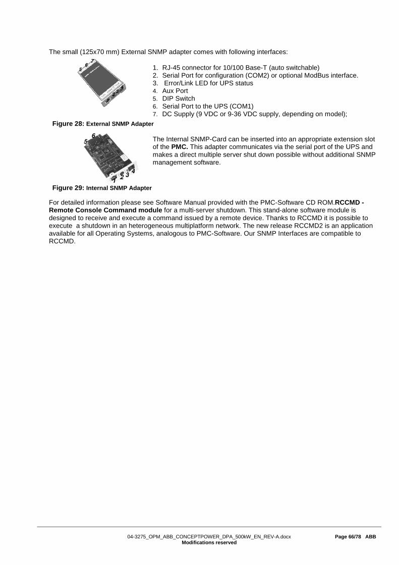
04-3275_OPM_ABB_CONCEPTPOWER_DPA_500kW_EN_REV-A.docx Page 66/78 ABB
Modifications reserved
The small (125x70 mm) External SNMP adapter comes with following interfaces:
1. RJ-45 connector for 10/100 Base-T (auto switchable) 2. Serial Port for configuration (COM2) or optional ModBus interface. 3. Error/Link LED for UPS status 4. Aux Port 5. DIP Switch 6. Serial Port to the UPS (COM1) 7. DC Supply (9 VDC or 9-36 VDC supply, depending on model);
Figure 28: External SNMP Adapter
The Internal SNMP-Card can be inserted into an appropriate extension slot of the PMC. This adapter communicates via the serial port of the UPS and makes a direct multiple server shut down possible without additional SNMP management software.
Figure 29: Internal SNMP Adapter
For detailed information please see Software Manual provided with the PMC-Software CD ROM.RCCMD - Remote Console Command module for a multi-server shutdown. This stand-alone software module is designed to receive and execute a command issued by a remote device. Thanks to RCCMD it is possible to execute a shutdown in an heterogeneous multiplatform network. The new release RCCMD2 is an application available for all Operating Systems, analogous to PMC-Software. Our SNMP Interfaces are compatible to RCCMD.

04-3275_OPM_ABB_CONCEPTPOWER_DPA_500kW_EN_REV-A.docx Page 67/78 ABB
Modifications reserved
10 TECHNICAL SPECIFICATIONS
10.1 CONCEPTPOWER DPA 500 - SYSTEM DESCRIPTION ABB’s Conceptpower DPA 500 is a high-power, modular and transformer-free UPS system for organizations who need zero downtime. The UPS is built using true online double conversion technology and provides low cost of ownership. True modularity up to 3 MW Now you can have a UPS size to exactly fit your needs: the Conceptpower DPA 500 is the only modular UPS on the market that can easily be scaled up to 3MW of clean, reliable power. This scalability means that there is no need to over-specify the original configuration as power modules can simply be added, as needed, in the future. True parallel architecture Reliability and availability are ensured by the Conceptpower DPA 500’s proven Decentralized Parallel Architecture (DPATM). Each module contains all the hardware and software required for full system operation. They share no common components. Each UPS module has its own independent static bypass, rectifier, inverter, logic control, control panel, battery charger and batteries. With all the critical components duplicated and distributed between individual units, potential single points of failure are eliminated. Key Features of CONCEPTPOWER DPA 500
• 100 kW rated power module
• 500 kW rated power in single frame
• Extended power range: from 100 kW to 3 MW
• Unity output power factor (kVA = kW)
• AC-AC efficiency up to 96 %
• Efficiency in eco-mode ≥ 99 %
• Online Swap Modularity (OSM)
• Online serviceability
• Top or bottom cable entry (standard)
• Built-in back-feed protection (standard)
• Graphical display on system level
• DPA displays in each module
This Technical Datasheet (TDS) provides all technical specification required by IEC 62040-3, providing mechanical, electrical and environmental characteristics. It can be used for tendering and end-user requirements. CONCEPTPOWER DPA 500 is designed to respond to the actual UPS standards which are:
• safety, IEC / EN 62040-1
• EMC, IEC / EN 62040-2
• performance, IEC / EN 62040-3

04-3275_OPM_ABB_CONCEPTPOWER_DPA_500kW_EN_REV-A.docx Page 68/78 ABB
Modifications reserved
10.2 GENERAL CHARACTERISTICS
General characteristics - Frame Values Unit
Model: Conceptpower DPA 500
Power, rated: apparent 500 kVA active 500 kW Power, range 100 - 3000 kW UPS type: on-line, trasformerfree, modular, decentralized parallel architecture Parallel capability: up to 6 frames Battery: not included Performance classification: VFI-SS-111
Mechanical Dimensions (width × height × depth) 1580x1975x940 mm Mass, approx. (500kW system, with 5 modules) 975 kg Acoustic noise (acc. to IEC 62040-3) in normal mode (at <=25°C) at 100% / 50% Load 75 / 67
dBA in battery mode (at <=25°C) at 100% / 50% Load 73 / 66
Safety Access: operator/restricted Degree of protection against hazards and water ingress: IP 20
Electromagnetic compatibility compliant Emission UPS Cat / Immunity UPS Cat C3 / C3
Environmental Storage temperature range -25 - +70 °C Operative temperature range 0 - +40 °C Relative humidity range (non-condensing) ≤ 95 % Max. altitude without de-rating 1000 m
Additional and usual information Connection: 5 wires, 3 phase + N + PE Cable entry: top or bottom Accessibility: frontal only Color: Graphite Grey (RAL 7024) Color code: Pulverlacke N°4222903402

04-3275_OPM_ABB_CONCEPTPOWER_DPA_500kW_EN_REV-A.docx Page 69/78 ABB
Modifications reserved
General characteristics - Module Values Unit
Model: Conceptpower DPA 500
Power, rated: apparent 100 kVA active 100 kW UPS type: on-line, trasformerfree, modular, decentralized parallel architecture Parallel capability: up to 6 frames Battery: not included Performance classification: VFI-SS-111
Mechanical Dimensions (width × height × depth): active sub-module / passive sub-module 710x178x750 mm Mass, approx.: active sub-module / passive sub-module 55 / 54 kg
Additional and usual information Back feed protection: included Color: Black (RAL 9005)

04-3275_OPM_ABB_CONCEPTPOWER_DPA_500kW_EN_REV-A.docx Page 70/78 ABB
Modifications reserved
10.3 INPUT CHARACTERISTICS
Input characteristics UPS frame values
UPS module values
Unit
Power, rated: 500 100 kW Voltage (steady-state, r.m.s), rated: 3x380/220V+N
3x400/230V+N 3x415/240V+N
VAC
tolerance, refferred to 400/230V -10 / +15 at <100% load -20 / +15 at <80% load, -30 / +15 at <60% load
%
Frequency, rated 50 Hz tolerance, refferred to 50Hz -30/+40 % Current (r.m.s), rated (with battery charged and input 400/230V) 760 152 A maximum (with battery charging and input 400/230V) 835 167 A total harmonic distortion (THDi) < 3.5 % in-rush current < 100% of rated current % Power factor 0.99 @ 100% load Rated short-time withstand current (ICW) 25 for 1 s - kA, s AC power distribution system: TN-S, TN-C, TN-C-S, TT note: in static bypass mode or eco-mode TN-C and TN-C-S can cause PE current to rise above 5% of phase currents. phases required 3 neutral required yes
Additional and usual information Connection: 5 wires, 3 phase + N + PE Cable entry: top or bottom Accessibility: frontal Walk In/Soft Start: yes Back feed protection: yes

04-3275_OPM_ABB_CONCEPTPOWER_DPA_500kW_EN_REV-A.docx Page 71/78 ABB
Modifications reserved
10.4 OUTPUT CHARACTERISTICS
Output characteristics UPS frame values
UPS module values Unit
Power, rated: 500 100 kW
AC power distribution system: TN-S, TN-C, TN-C-S, TT available phases 3 neutral available yes Voltage (steady state, r.m.s.), rated: 3x380/220V+N
3x400/230V+N 3x415/240V+N
VAC
variation in normal mode / battery mode ± 1.5 / ± 1.5 % Total harmonic distortion (THDu), 100% load, normal mode: linear < 2.0 % non-linear (according to IEC 62040-3) < 4.0 Total harmonic distortion, 100 % load, battery mode: linear < 2.0 % non-linear (according to IEC 62040-3) < 4.0 Voltage unbalance and phase displacement, 100 % load unbalance 0 ° Voltage transient and recovery time, 100% step load: linear ± 4 % non-linear (according to IEC 62040-3) ± 4 % transfer normal mode --> battery mode 0 % Frequency (steady-state), rated: 50/60 Hz variation in normal mode (frq. Synchronized with mains) ± 2 / ± 4 % variation in battery mode (free-running) ± 0.1 Max synch phase error (referred to a 360° cycle) <2 ° Max slew-rate 1 Hz/s Nominal current (In), r.m.s. rated: 725 145 A
overload on inverter
0.5 @ 150% load, 5 @ 125% load, 20 @ 110% load
min
fault clearing capability normal mode and battery mode for 100ms 1711 (2.36xIn) 348 (2.4xIn) A Load power factor, rated 1 displacement (permissible lead-lag range) (all range) 0 %, s AC / AC efficiency in normal mode, linear load: 100% load 95.6
% 75% load 96.0 50% load 96.1 25% load 95.8 Eco-mode efficiency, linear load ≥ 99 % Crest – Factor (Load supported) 3:1 Static bypass Type: automatic, static switch in each module transfer time: inverter bypass / bypass inverter / in eco-mode <1 / <5 / <6 ms rated current 800 160 A fault clearing capability (bypass mode) for 20 ms 10xIn 10xIn A overload current on bypass mode (< 25°C) continuously @ 110% load min Maintenance bypass: optional on the frame Bypass protection fuse or circuit breaker rating 5x160 A, gL fuse

04-3275_OPM_ABB_CONCEPTPOWER_DPA_500kW_EN_REV-A.docx Page 72/78 ABB
Modifications reserved
10.5 BATTERY CHARACTERISTICS
Battery characteristics Values Unit
Technology: VRLA, vented lead-acid, NiCd Number of 12 V blocks (even and odd) 42 - 481) Number of 1.2 V NiCd cells (even and odd) 420 - 4801) Battery charger: decentralized, each module has its own charger Max. current charger capability 60 A Max. power charger capability 30 kW Floating voltage (VRLA / NiCd) 2.25 / 1.40 VDC End of discharge voltage (VRLA / NiCd) 1.65 / 1.05 r.m.s. ripple current (percentage of the battery capacity ) 2 % Temperature compensation: optional Battery test: automatic and periodic battery test (selectable)
1) IMPORTANT NOTES: - for small autonomies (< 20 minutes) the UPS supports 40 - 50 12V blocks - the range 42 - 48 supports any autonomy. - at output voltage 415/240VAC the minimum 12V block is 42. 10.5.1 Graph: AC / AC efficiency with linear load @ cos(phi) 1 *
* tolerance of ± 0.2% applies on all figures.
95.8%96.1% 96.0% 95.6%
90%
92%
94%
96%
98%
100%
0 10 20 30 40 50 60 70 80 90 100
AC/AC Efficiency with linear, resisitve load
η
Load [%]

04-3275_OPM_ABB_CONCEPTPOWER_DPA_500kW_EN_REV-A.docx Page 73/78 ABB
Modifications reserved
10.6 USER INTERFACE - COMMUNICATION
System Display 7” touchscreen display (one per frame)
DPA display (or module display) 2 x 20 character LCD display (one per module)
MIMIC diagram LED-indicator, 5x green/red LEDS (one per module)
RS232 on Sub-D9 port RS232 on USB port For monitoring and integration in network management
Customer Interfaces : Inputs DRY PORT
1 Remote Shut down [EMERGENCY OFF (Normally closed)] 1 GEN-ON (Normally open) 1 Programmable Customer’s Inputs (Normally open) 1 Temp. Sensor for Battery Control
Customer Interfaces : Outputs DRY PORT
6 voltage free contacts For remote signaling and automatic computer shutdown
RS485 on RJ45 port
Remote monitoring system with remote panel (graphical display) Optional
RS485 on RJ45 port For multidrop purpose Optional
Slot for SNMP SNMP card For monitoring and integration in network management Optional
10.6.1 System Display
The user-friendly touchscreen graphical display on the system level offers the opportunity of directly monitoring the system status as well as the status of each individual module. The graphical display additionally provides all the measurements (module and system level) and the user is able to transfer from INVERTER to BYPASS and vice-versa. All other commands must be performed on the DPA display. With both displays in place (module and system level), the UPS offers full user friendliness without making compromises on robustness.

04-3275_OPM_ABB_CONCEPTPOWER_DPA_500kW_EN_REV-A.docx Page 74/78 ABB
Modifications reserved
10.6.2 DPA Display
The 2 x 20 character LCD simplifies the communication with the UPS. The menu driven LCD enables the access to the EVENT REGISTER, or to monitor the input and output U, I, f, P, Autonomy Time and other Measurement’s, to perform commands like start-up and shut-down of INVERTER or load transfer from INVERTER to BYPASS and vice-versa and finally it serves for the DIAGNOSIS (SERVICE MODE) for adjustments and testing. 10.6.3 Mimic Diagram
The mimic diagram serves to give the general status of the UPS. The LED-indicators show the power flow status and in the event of mains failure or load transfer from inverter to bypass and vice-versa the corresponding LED-indicators will change colour from green (normal) to red (warning). The LED’s LINE 1 (rectifier) and LINE 2 (bypass) indicate the availability of the mains power supply. The LED’s INVERTER and BYPASS if green indicate which of the two are supplying power to the critical load. When the LED-indicator BATTERY is lit it means that the battery due to mains failure is supplying the load. The LED-indicator ALARM is a visual indication of any internal or external alarm condition. At the same time the audible alarm will be activated.
10.7 CUSTOMER INTERFACES 10.7.1 Customer inputs dry ports: Terminal blocks X3 / 3-14
Connection of Remote Shut down facilities, Generator Operation, Customers specials (see UM Section 9 / OPTIONS) 10.7.2 Outputs dry ports: Terminal blocks X2 + X3 / 1-2
Provision of signals for the automatic and orderly shutdown of servers, AS400 or Automation building systems

04-3275_OPM_ABB_CONCEPTPOWER_DPA_500kW_EN_REV-A.docx Page 75/78 ABB
Modifications reserved
10.7.3 Interlock castell function: Terminal block X1
This function allows a secure transfer from inverter (normal operation) to external maintenance bypass and vice-versa. During normal operation the external bypass is locked in position OFF. Only when the UPS is/are transferred to static bypass mode, the lock on the external bypass is released and it possible to switch to position ON. The transfer from maintenance bypass back to normal operation happens exactly the other way around. The release signal is 230VAC when the maintenance bypass is free and 0V when locked.
=~
~=
=~
~=
=~
~=
Load
Line1 - RectifierLine2 - Bypass
UPSP01
UPSP02
UPSP03
MBSAuxiliarycontacts
Lock 1
Key 1
Solenoid 1
X1X3X3X3
Output isolator
Lock 2
Solenoid 2
Key 2
Customer interface
Customer interface
Customer interface

04-3275_OPM_ABB_CONCEPTPOWER_DPA_500kW_EN_REV-A.docx Page 76/78 ABB
Modifications reserved
ll Terminals X1-X3 can hold Cable from 0.2mm2 – 1.5mm2 X1 is a 230VAC output which allows to interface with a interlock system. All X2 are potential free contacts and are rated: Max 250Vac/8A; 30Vdc/8A; 220Vdc/0.12A All X3 (except X3 5/6 which is a 12VDC source) are inputs, cable max. R 50Ω at 20mA
Block Terminal Contact Signal On Display Function
X3
X3 / 14
GND - Battery Temperature (only the optional battery sensor from ABB is compatible) X3 / 13 +3.3VDC -
X3 / 12
GND GENERATOR_ OPER_ON
Generator Operation (N.O.) Min. contact load 12V / 1mA X3 / 11 +12Vdc
X3 / 10
GND PARRALEL_SW_OPEN PARRALEL_SW_CLOSE
External Output Breaker (N.O.) Min. contact load 12V / 20mA. X3 / 9 +12Vdc
X3 / 8
GND EXT_MAN_BYP External Manual Bypass (Ext. IA1)
(N.O.) Min. contact load 20mA X3 / 7 +12Vdc
X3 / 6 12V
GND
+12Vdc - + 12 VDC source (UPS protected) (Max. 200mA) X3 / 5 GND -
X3 / 4
GND REMOTE_
SHUTDOWN-
RSD (Remote Shut down) Default setting: disabled. Possibility to enable and set NO or NC via NewSet. X3 / 3 +12Vdc
X3 / 2
- REMOTE_
SHUTDOWN-
RSD (Remote Shut down ) for external switch Max. 250Vac/8A ;30Vdc/8A ;110Vdc/0.3A ;220Vdc/0.12A
X3 / 1 -
X2
X2 / 18
- - Common X2 / 17 - - Relais AUX
(function on request, to be defined) X2 / 16 - -
X2 / 15
COMMON_ALARM Common X2 / 14 ALARM No Alarm Condition X2 / 13 Common Alarm (System) X2 / 12
LOAD_ON_MAINS Common X2 / 11 Message No Load on Bypass X2 / 10 Load On Bypass (Mains) X2 / 9
BATT_LOW Common X2 / 8 ALARM Battery Ok X2 / 7 Battery Low X2 / 6
LOAD_ON_INV Common X2 / 5 Message No Load on Inverter X2 / 4 Load on Inverter X2 / 3
MAINS_OK Common X2 / 2 ALARM Mains Failure
X2 / 1 Mains Present
X1 X1 / 2
2AT
- EXT_MAN_BYP
Interlock Function Max. 30Vdc/2A; 60Vdc/0.7A (Ext Manual Bypass) / 2AT X1 / 1
-
Customer Interface Conceptpower DPA 500
GND
IN
GND
IN
GND
IN
GND
IN
GND
IN
C
NO
CNCNO
CNCNO
CNCNO
CNCNO
CNCNO
CNCNO

04-3275_OPM_ABB_CONCEPTPOWER_DPA_500kW_EN_REV-A.docx Page 77/78 ABB
Modifications reserved
10.8 OPTIONS
- Maintenance bypass - SNMP cards - Battery Cabinet - Parallel KIT for paralleling multiple frames - Wooden box - Temp. sensor for battery temp. control
10.9 ON REQUEST
- INPUT / OUTPUT transformers for galvanic isolation or special voltages - Bypass transformer - IP 21
10.10 INSTALLATION PLANNING – UPS POSITIONING Clearances needed to allow proper airflow on the UPS system and to allow door opening.
Minimum clearances for single UPS
UPS Model A1 (mm)
B1
(mm) C (°)
D (mm)
DPA 500 300 1000 115° 400
Minimum clearances for UPS + other cabinets in row
UPS Model A2 (mm)
B2
(mm) C (°)
D (mm)
DPA 500 300 1000 115° 400
Top view and indication of the minimum clearances for single UPS.
Top view and indication of the minimum clearances for UPS + other cabinets in row .
10.11 HEAT DISSIPATION
Module quantities 1 2 3 4 5
UPS power rating kW 100 200 300 400 500
Heat Dissipation with 100% linear load
W 4500 9000 13500 18000 22500 BTU 15359 30717 46076 61434 76793
Heat Dissipation with 100% non-lin.load (acc. to IEC 62040-3)
W 5710 11420 17130 22840 28550 BTU 19488 38976 58465 77953 97441
Airflow (25° - 30°C) with 100% non-lin. Load (acc. to IEC 62040-3) m3/h 1200 2400 3600 4800 6000
Heat Dissipation without load W 660 1320 1980 2640 3300
B1
A1
UPS Cabinet
door opening
C
D top clearance is only needed if there is no side clearance.
B2
UPS Cabinet
A2
Battery cabinet or other equipment
Battery cabinet or other equipment
door opening
C
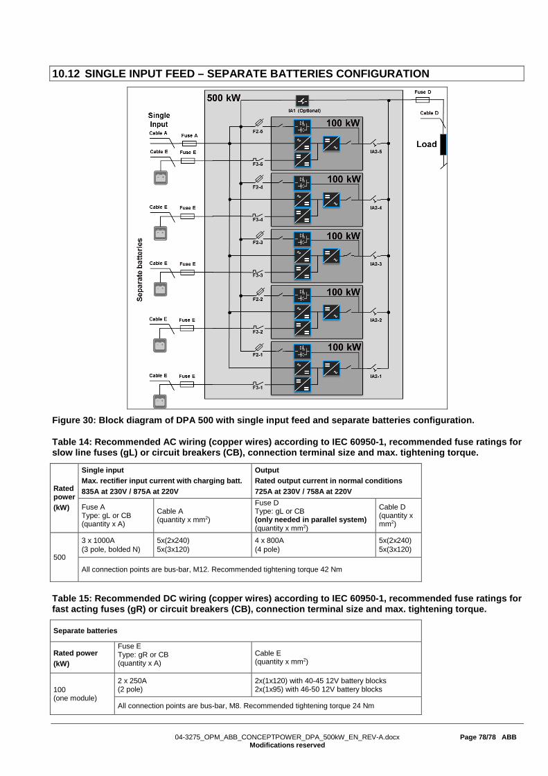
04-3275_OPM_ABB_CONCEPTPOWER_DPA_500kW_EN_REV-A.docx Page 78/78 ABB
Modifications reserved
10.12 SINGLE INPUT FEED – SEPARATE BATTERIES CONFIGURATION
Figure 30: Block diagram of DPA 500 with single input feed and separate batteries configuration.
Table 14: Recommended AC wiring (copper wires) according to IEC 60950-1, recommended fuse ratings for slow line fuses (gL) or circuit breakers (CB), connection terminal size and max. tightening torque.
Rated power (kW)
Single input Max. rectifier input current with charging batt. 835A at 230V / 875A at 220V
Output Rated output current in normal conditions 725A at 230V / 758A at 220V
Fuse A Type: gL or CB (quantity x A)
Cable A (quantity x mm2)
Fuse D Type: gL or CB (only needed in parallel system) (quantity x mm2)
Cable D (quantity x mm2)
500
3 x 1000A (3 pole, bolded N)
5x(2x240) 5x(3x120)
4 x 800A (4 pole)
5x(2x240) 5x(3x120)
All connection points are bus-bar, M12. Recommended tightening torque 42 Nm
Table 15: Recommended DC wiring (copper wires) according to IEC 60950-1, recommended fuse ratings for fast acting fuses (gR) or circuit breakers (CB), connection terminal size and max. tightening torque.
Separate batteries
Rated power (kW)
Fuse E Type: gR or CB (quantity x A)
Cable E (quantity x mm2)
100 (one module)
2 x 250A (2 pole)
2x(1x120) with 40-45 12V battery blocks 2x(1x95) with 46-50 12V battery blocks
All connection points are bus-bar, M8. Recommended tightening torque 24 Nm

04-3275_OPM_ABB_CONCEPTPOWER_DPA_500kW_EN_REV-A.docx Page 79/78 ABB
Modifications reserved
10.13 DUAL INPUT FEED – COMMON BATTERY CONFIGURATION
Figure 31: Block diagram of DPA 500 with dual input feed and common battery configuration.
Table 16: Recommended AC wiring (copper wires) according to IEC 60950-1, recommended fuse ratings for slow line fuses (gL) or circuit breakers (CB), connection terminal size and max. tightening torque.
Rated power (kW)
Rectifier input Max. rectifier input current with battery charging 835A at 230V / 875A at 220V
Bypass input Max. bypass input current 732A at 230V / 765A at 220V
Output Rated output current in normal conditions 725A at 230V / 758A at 220V
Fuse B Type: gL or CB (quantity x A)
Cable B (quantity x mm2)
Fuse C Type: gL or CB (quantity x A)
Cable B (quantity x mm2)
Fuse D Type: gL or CB (only needed in parallel system) (quantity x mm2)
Cable D (quantity x mm2)
500
3 x 1000A (3 pole, bolded N)
5x(2x240) 5x(3x120)
3 x 800A (3 pole, bolded N)
5x(2x240) 5x(3x120)
4 x 800A (4 pole)
5x(2x240) 5x(3x120)
All connection points are bus-bar, M12. Recommended tightening torque 42 Nm
Table 17: Recommended DC wiring (copper wires) according to IEC 60950-1, recommended fuse ratings for fast acting fuses (gR) or circuit breakers (CB), connection terminal size and max. tightening torque.
Common battery
Rated power (kW)
Fuse E Type: gR or CB (quantity x A)
Cable E (quantity x mm2)
500
2x1250A (2 pole)
2x(3x240) 2x(4x150)
All connection points are bus-bar, M12. Recommended tightening torque 42 Nm

04-3275_OPM_ABB_CONCEPTPOWER_DPA_500kW_EN_REV-A.docx Page 80/78 ABB
Modifications reserved
11 REVISION HISTORY
Edition Date Section(s) Revision 19.08.2014 N/A Second Release 07.10.2014 4 / 10 Changed the tightening torque
from: Max. tightening torque 26.4 Nm / (84.8 Nm) to: Recommended tightening torque 24 Nm / (42 Nm)
6 6.2.3 Correct the DIP Switch SW 1-9 configuration
6.5.5 Correct the Definition of a Single/ Multi-Cabinet Chain table
(DIP Switch SW1-9)
150305 0 page 2, Correct the “CE” logo 2 2.2 Correct the “CE” logo 6.4 Update the entire chapter 6.4 with the new graphical display 10.6.1 Changed to display picture REV-A (30.03.2016)
0 Added the document information table
2.4 Corrected the dimensions w/o packaging in mm on the table 2 Corrected the standard packaging and wooden box weights on the table 3 5.1.2 Modified the “X1-Interlock function” row on the table 5.1.6 On the second sentence, corrected the phoenix terminal X2 with X3. 6.2.3 Modified the entire chapter 6.2.3 DIP-Switch configuration from a DIP-switch
SW1—9 to a DIP-switch SW1-6 (refer to the following release to more information)
6.4.6 Corrected the reference from “see 6.2.3 navigation” to “see 6.4.4” 6.5.5 Corrected the DIP-switch table from DIP SW 1-9 to DIP SW 1-6 6.9 Corrected the point 1 sentence with “transfer the load to bypass on the control
panel of any module” instead “of three module” 10.6.2 Removed: see the user manual of the Conceptpower DPA S2 at the end of the
sentence 10.7.3 Modified the “Interlock castell function: Terminal block X1” chapter 11 Added the revision history inside the document Last page Moved the contacts details from the second page to the last one

Contact us www.abb.com/ups [email protected]
© Copyright ABB. All rights reserved. Specification subjects to change without notice.