conclusions and future work 6.1 general
TRANSCRIPT

Chapter 6
C O N C L U S I O N S A N D F U T U R E W O R K
6.1 General
The cost o f construction is one o f the key factors that can influence the decision making about the adoption o f alternative building materials. For this, a cost study is carried out by adopting the alternative wall ing materials and slab systems to a typical three storey office building. The building is of length 28.8 m and a width o f 18.0 m. It is not provided with any internal partition walls. In order to determine the effect o f the grid spacing on the cost wi th alternative materials, two grid arrangements were selected in one direction. It is a grid spacing o f 4.5m.x 4 (Building 1) and 6.0 m. x 3 (Building 2) for the side with a width o f 18 in. In the other direction, 8 bays were selected wi th a spacing o f 3.6 m. The details o f the cost study are shown in chapter 5.
When performing cost studies for the use in project evaluation purposes, there are two different cost components, namely the actual cost and the cost that includes the provision for contingencies (10%), escalation (10%) and V A T (15%). This means that the actual cost on Bi l l o f Quantities wi l l be enhanced by about 35% to determine the projected cost o f the building. Therefore, any reduction in the actual cost o f the building can make a project proposal much more attractive at the project appraisal stages. In this study, attention was focused on both these. The escalating costs o f traditional building materials are increasing the cost o f construction at a rapid rate which may make some building projects not viable in financial terms. One solution to this is the adoption o f alternative building materials that can provide adequate structural performance and durability at a lower cost. It is shown that the adoption o f alternative wall ing materials w i l l not need much deviation since the presently adopted design philosophy uses an unbraced frame for carrying most o f the lateral and vertical loads. The same approach makes the adoption o f the precast beam slab system also straightforward. This is an encouraging f inding for the designers who contemplate the use o f these alternatives in future.
The detailed cost study carried out for a typical office building has indicated that the cost o f structural members can be reduced by about 2.5%-5% from the conventional solid slab construction. When the savings possible with plastering are considered with machine moulded blocks, the overall cost o f the building can be reduced by about 14%. Therefore, there is a strong reason to pursue further research and development in the adoption o f alternative building materials even for large projects in order to make building projects more attractive in financial terms.
72

6.2 FUTURE WORK
In this research study, attention was focused on the alternative materials that can be used for loadbearing walls and floor slabs o f multistorey buildings. It may be possible to find alternative roof systems such as those using optimised steel designs to replace the traditional timber framework since timber has become a depleting source.
Another area that can be useful is the performance o f alternative surface coatings and plasters that can be used with cement stabilised soil blocks and chip concrete blocks. A successful development o f such water repellent coatings would enable the use o f cement stabilised soil blocks with more confidence even at locations where there is a risk o f occasional floods.
It would be useful to assess the performance o f cement stabilised soil blocks as a loadbearing material at locations where foundations are liable to undergo differential settlements such as clayey soils. The development o f cost effective strong foundation systems could also be useful.
For the composite slab system, the use o f economical non structural screeds such as 1:3:3 cement, sand and 8 mm chips could be beneficial with respect to stiffening the slab. A detailed study into the feasibility o f using these screeds properly could be beneficial since this stiffening can be used to improve the dynamic characteristics o f the composite slab, in addition to reducing deflections associated with heavy loads.
I f cement stabilised soil blocks are manufactured as commercial ventures, it may be appropriate to carry out detailed environmental impact assessment so that adequate measures could be taken to minimise the damage to environment.
When alternative building materials and methods are introduced, it w i l l be important to determine the strategies that can be adopted for popularising such techniques so that the majority o f the population could enjoy any benefits.
73

REFERENCES
Auram Press 3000 manual (undated), Production and use of compressed earth blocks, CRATerre-EAG, Aurovi l le building centre, India, 141 p.
Bryan, A. J. (1988 a), "Criteria for the suitability o f soil for cement stabilisation", Building and Envionment, Vo l . 23, No. 4 , pp 309-320.
Bryan, A. J. (1988 b), "Soil/cement as a wall ing materal - 1, Stress/strain properties" Building and Environment, Vo l . 23, No. 4, pp 321-330.
Bryan, A. J. (1988 c), "Soi l / cement as a wall ing material - 2, Some measures o f durabil ity", Building and Environment, Vo l . 23, No. 4 , pp 331-336.
BS 12 : 1978, British Standard Specification for ordinary and rapid hardening port land cement, B.S.I., London.
BS 1377 : 1975, Methods oftest for soil for civil engineering purposes, B. S. I., London.
BS 5628 : 1978: Part 1, Code of practice for structural use of masonry - Unreinforced masonry, B.S.I., London.
BS 6399 : Part 1 : 1984, Code ofpractice for dead and imposed loads, B.S.I., London.
BS 8110 : Part 1 : 1985, British Standard for Structural Use of Concrete, B.S.I., London.
BS 8110 : Part 2 : 1985, British Standard for Structural Use of Concrete, B.S.I., London.
Building Regulations (1985), City of Colombo Development Plan, Volume I I , Colombo Municipal Council, 74 p.
Building Shedule o f Rates, Department o f Buildings, Ministry o f Housing and Construction, Sri Lanka.
Chandrakeerthy, S. R. De S. (1987), "Influence o f some current brick laying practices on structural behaviour o f br ickwork", Engineer, pp 90 - 102.
Chandrakeerthy, S. R. De S. (1991 a), "Control o f rain penetration o f masonry with special reference to Sri Lankan conditions", Engineer, March, pp 29-38.
Chandrakeerthy, S. R. De S. (1991 b), "Detail ing and other important considerations o f blockwork", Engineer, September, pp 3-19.
74

Crowley, M.H. "Portland cement: The construction industries .greenhouse gas problem " in CIB 2003 International Conference on Smart and sustainable built environment Nov. 19-21, 2003. Brisbane, Australia.
Guillaud H. , Jeffroy T. & Odul P., (1995), Compressed earth blocks, Vol . 2 , CRATcrre-EAG, The international centre for earth construction, France, 148 p.
Hendry, A. W., Sinha, B. P., Davies, S. R. (1981), An introduction to loadbearing design, Ellis Horwood, England, 184 p.
Jamal, S. Q., Sheikh, A. S. (1987), "The use and performance o f soil stabilised building blocks in flood affected rural areas, Proceedings, Building materials for low-income housing,Tha\\and, January, E & F.N. Spon, pp 302 - 309.
Jayasinghe C. , Perera A.A.D.A.J. "Alternative concrete floor slab system for residential buildings", Engineer , Journal of Institution of Engineers, Sri lanka, Vo l xxx i i i , No 2 September 2000 pp 54-65. (2000 a)
Jayasinghe C . , Perera A.A.D.A.J. An alternative Concrete Floor Slab System for Residential Buildings pp 54 -65 Journal Engineer. Septwember 2000
Jayasinghe C , (1999) Alternative Building Materials for Sri Lanka, PhD. Thesis, Department o f Civi l Engineering, University o f Moratuwa. ( 2000 b)
Jayasinghe C , Perera A.A.D.A.J. Load testing on a reinforced precst slab system for Residential Buildings Transactions (2000) pp96-106
Jayasinghe C , Studies on Load Bearing Characteristics o f Cement Stabilised Soil Blocks Transactions (1999) pp 63-72
Jayasinghe, M. T. R (1997), Loadbearing brickwork construction for Sri Lanka, Strad Consultants, Sri Lanka, 141 p.
Jayasinghe M. T. R. (1998), "Loadbearing construction with local bricks", Engineer, Journal o f IESL, Vol . xxv i i , No. 1, pp 49-57.
Jayasinghe, M. T. R., Maharachchi, D. P. K. (1998), "Use o f reinforced brickwork for crack freeloadbearing construction", Proc. Research for Industry - 1998, University o f Moratuwa, Sri Lanka, November, pp 38-51.
Jayasinghe, M. T. R (2002), Suitability of hand moulded chip concrete blocks for single storey houses Engineer, Journal o f IESL, September pp 24-30.
75

Kulasinghe, A. N. S. (1998), "Bui ld ing research and development", Newsletter o f National Bui lding Research Organisation o f Sri Lanka, March/June, Vo l . 8, Number 1-2, pp 1-4.
Lahlauh E. A. & Waldron P., (1992), "Memebrane action in one way slab strips", Proceedings of Institution of Civil Engineers, Structures and Buildings, 94, Nov. pp 419-428.
McHendry, P. G., May, G. W. (1984), Adobe and rammed earth buildings, A Wiley Interscience Publications, New York, 217 p.
Moss R. M., (1993), "Load testing o f beams and block concrete floors", Proceedings of Institute Civil Engineers, Structures and Buildings, 99, May, pp 211-223.
Moss R. M. (1994), "Assessment o f stiffness increase due to non-structural screeds", The Structural Engineer, Vol . 72, No. 14, July, pp 221-228.
Perera A. A. D. A. J., (1992), "Lessons from used low cost housing methods", Transactions - Institute of Engineers, Sri Lanka, pp 128-132.
Perera A. A. D. A. J., (1993), Landcrete blocks, Research Monograph, Department o f Civ i l Engineering, University o f Moratuwa, 16 p.
Perera, A. A. D. A. J. (1994), "Cement stabilised soil block houses", Trasactions -Institution of Engineers, pp 115 - 128.
Perera, A. A. D. A. J. & Jayasinghe, C. (1995), Introduction of compressed soil blocks to Sri Lanka, Research Report, Department o f Civ i l Engineering, University o f Moratuwa, 116 p.
Ranasinghe, M. (1997), "Clay miniming for building materials: Future land use", Engineer, Vo l . X X V I , December, pp 42-49.
Reddy, B. V. , Jagadish , J. S. (1989), "Properties o f soil - cement block masonry", Masonry International, Vo l . 3, No. 2, October pp 80-84.
Reddy, B. V. (1995), "Wal ls using stabilised mud blocks", Proceedings, Building construction for district primary education programme of West Bangalore, Salt Lake City, India. Jayasinghe C. , Perera A.A.D.A.J.
Saxton, R. H. (1995), "The performance o f cob as a building material", The Structural Engineer, Vo l . 73, No. 7, pp 111 -115
SLS 855:Part I: 1989, Specification for Cement Blocks- Requirements, SLSI, 19p.
76

SLS 855: Part 2: 1989, Specification for Cement Blocks- Test Methods SLSI, 12pp-16pp
Smith B. S. & Coull A., (1991), Tall building structures, Jon Wiley, New York, p 537.
Taranath, B. S. (1988), Strucutural analysis and design of tall buildings, McGraw Hi l l , New York, 739 p
Thorburn, S (1997), "The challenges o f structural engineering : safety with economy and harmony", The Structural Engineer, Vo l . 75, No. 20, pp 349-354.
Vembersky, J. N. J. A. (1994), "Precast concrete in buildings today and in the future", The Structural Engineer, Vo l . 72, No. 15, Aug, pp 237-242.
Wil l iams, M. S., Waldron, P. (1994), "Evaluation o f methods o f predicting occupant induced vibrations in concrete floors", The Structural Engineer, Vo l . 72, No. 20, pp 334-340.
77

APPENDIX A
A.l Design of precast concrete reinforced concrete slab
A.2 DESIGN OF COMPOSITE PRECAST BEAM SLAB SYSTEM
Design o f composite precast beam slab system was clone for two buildings with grid intervals at 3.6m.and 4.5m. in one bui lding and grid intervals at 3.6m.and 6.0m.intervals in the other building. The length and the width o f the two buildings are same. Both o f them are three storied buildings and the length and the width are 28.8m. and 18.0m. They are named as Bui lding I and Bui lding 2.
In both o f these buildings,3.6m. long precast beams and 300mm. wide precast slabs are selected for the design o f precast beam slab system.
I i " e
G
E •o B
OO
e
G
E •o B
OO
e
G
E •o B
OO
E OO
,
B
E
B
OO
,
, ,
B
E
B
OO
4.5m | 4.5m | 4.5m j <l.5in
I 8 .0m
Figure A.l Plan of the Building 1 with grid intervals at 3.6 in. and 4.5 in. intervals

3.6m
3.
6m
3.6m
3.
6m
E OO OO
3.6m
E OO OO
3.6m
3.
6m
3.6m
6 . 0 m 6 . 0 m 6 . 0 m
18.0m
6 . 0 m
Figure A.2 Plan of the Building 2 with grid intervals at 3.6 m. and 6.0 m. intervals
The fol lowing design data has been used for the structural design o f composite reinforced concrete precast beam slab system.
Density o f concrete = 24 kN /m 3
Weight o f finishes = 0.5 kN /m 2 (assuming 20 mm thick cement rendering) Weight o f partitions (movable) = 1.0 kN /m 2
Imposed load = 2.7 kN o f concentrated load or 2.5 kN /m 2 o f uniformly distributed load Construction load = 0.9 kN o f concentrated load Cover to reinforcement = 25 mm (BS 8110) Reinforcement used = 6 mm diameter Grade 250 mi ld steel bars
A.3 The design of precast concrete slabs
A slab panel o f length 1500mm, width 300 mm and o f dimensions shown in Figure.A.3 was used for the calculations. These slab panels can be supported either by load bearing walls or reinforced concrete beams o f suitable cross section. An end bearing o f 40 mm was used with the slab panels.
79

Figure A.3 The shape of the precast panel used for composite slab
r " 5 5 ~ 75 ELEVATION
300 300
1500
(dimensions in mm)
300 PLAN
Figure A.4 Plan & elevation of the pre cast slab panel
80

The slab is designed for the fol lowing load cases.
1. Slab subjected to a uniformly distributed imposed load o f 2.5 kN/m with an allowance o f 0.5 kN /m 2 for finishes and 1.0 kN /m 2 for movable partitions.
2. Slab subjected to a concentrated imposed load o f 2.7 kN acting at the centre with an allowance o f 0.5 k N / m 2 for finishes and 1.0 k N / m 2 for movable partitions.
3. Precast slab subjected to a concentrated load of 0.9 kN acting at the centre during the construction.
A.3.1.1 Design for a uniformly distributed load
The precast panels w i l l form a continuous floor slab once connected with insitu cast concrete. Thus, each panel can be subjected to a uniformly distributed imposed load o f 3.5 k N / m 2
Design for flexure
Dead load = 0.3 x 0.075x 24 = 0.54 kN / m
Superimposed dead load = 0.5 x 0.3 = 0.15 kN/m
Imposed load = 3.5 kN /m 2
Design bending moment at mid span
= 1.4 x (0.54 + 0.15) x 1.462/8 +{ 1.6 x (3.5x 0.3) x 1.462/8} = 0.71 kNm
The quantity o f reinforcement is calculated as specified in CI 3.4.4.4 o f BS 8110: Part 1: 1985
Effective depth = 75 -25 -3 = 47 mm
K= M/bd 2 f c u = 0.71 x 10 6 / 300 x 47 2 x 20 = 0.053< 0.156
Z = d{0.5 + (0.25 - K/0.9) , / 2 } = 0.948 d < 0.95 d
A s = M/ 0.87 f y Z = 0.7lx 106 / 0.87 x 250 x 0.948 x 47 = 73.26 m m 2
Three 6 mm diameter mi ld steel bars are sufficient. However, two 6mm diameter & one 8 mm. diameter mild steel bars wi l l be used.
81

Design for shear
Design shear force = 1.4 (0.54 + 0.15) x 1.46/2 +(1.6 x 4.5 x 0.3) x 1.46/2 = 2.28kN
Design shear stress = v = 2.28x10 3 /(300 x 47) = 0.162 (Table 3.9 )
100 Ag/byd = 100 x 108.9/(300 x 47) = 0.352<3
400/d = 400/47 = 8.51
v c = 0.79(0.758) l / 3 (8.51) l / 4 / l .25 = 0.983
v < v c
Hence satisfactory.
Determination of bearing width
It is necessary to check whether a bearing width o f 40 mm would be sufficient for the precast panels.
Net bearing width required is given in CI 5.2.3.2 o f BS 8110: Part l:1985as the design ultimate support reaction per member divided by the product o f design effective bearing length and ultimate bearing stress. The design ultimate support reaction is 2.28 kN as calculated above. The bearing length per panel is 300 mm and the ultimate bearing stress is 0.4 x f c u. Thus, the bearing width required can be calculated as follows.
Net bearing width = 2.28x 10³/(300 x 0.4 x 20) = 0.95 mm
Thus, a bearing width o f 40 mm should be provided (CI 5.2.3.2 o f BS 8110/1).
A.3.1.2 Design for a concentrated load
The magnitude o f the concentrated load that acts as an imposed load at the centre o f a precast panel is 2.7 kN. When this load acts on the panel, load sharing between adjacent panels should be available since the panels are connected with insitu concrete. However, the precast panel is designed for a ful l load o f 2.7 kN ignoring any reduction in the load due to load sharing.
Dead load = 0.3 x 0.075 x 24 = 0.54 kN / m
Superimposed dead load = 0.5 x 0.3 = 0.15 kN/m
82

Design bending moment with concentrated load assuming that one panel resists the total load
= {1.4 x (0.54 + 0.15) x 1.462/8} + {1.6 x 2.7 x 1.46/4} = 1.82 kNm
Effective depth = 75 -25 -3 = 47 mm
K = M / b d 2 f c u = 1.82 x 10 6 / 300 x 47 2 x 20 = 0.14 < 0.156
Z = d{ 0.5 + ( 0.25 - K/0.9) , / 2 } = 0.807 d (CI 3.4.4.4, BS 8110/1)
A s = M/0.87f y Z = 1.82 x 10 6 /(0.87 x 250 x 0.807 x 47) = 220 m m 2
Number o f 6 mm diameter bars required = 7.7
It should be noted that there would be load sharing to a certain extent between precast panels once those are connected with insitu cast concrete. Since the aim was to verify whether BS 8110: Part 1: 1985 could be used for the design o f precast panels for construction and service loads, lesser amount o f reinforcement than required for this case was provided. The reinforcement provided is 2 Nos, 6 mm diameter and one number o f 8 mm. diameter mi ld steel bars. In Section A.3.1.4, it is shown that this amount o f reinforcement is satisfactory with load sharing.
A s provided = 2x28.3 + 50.3 = 106.9 m m 2
This quantity has to be checked with the minimum amount o f reinforcement.
100 A s / bh = 0.475% > 0.24% (C1.3.12.6, BS 8110/1)
Hence satisfactory.
Design for shear
In order to determine the design shear force, the concentrated load o f 2.7 kN should be located very close to the face o f the support. Thus, the shear force due to the point load is taken as 2.7 kN for the calculations.
Design shear force = 1.4 (0.54 + 0.15) x 1.46/2 +(1.6 x 2.7/2) = 2.64 kN
Design shear stress = 2.64 x 10³ /(300 x 47) = 0.187kN/m 2
100 A s /b v d = 100 x 106.8/(300 x 47) = 0.758 <3
83
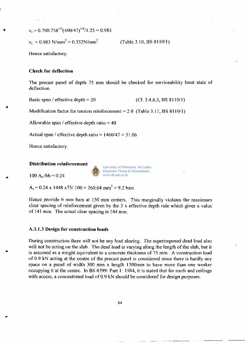
v c = 0.790.758 l / 3(400/47) l / 4 /1.25 = 0.983
v c = 0.983 N/mm 2 > 0.352N/mm 2 (Table 3.10, BS 8110/1)
Hence satisfactory.
Check for deflection
The precast panel o f depth 75 mm should be checked for serviceability l imit state o f deflection.
Modification factor for tension reinforcement = 2.0 (Table 3.11, BS 8110/1)
Allowable span / effective depth ratio = 40
Actual span / effective depth ratio = 1460/47 = 31.06
Hence satisfactory.
Distribution reinforcement in transverse direction
A s = 0.24 x 1448 x75/ 100 = 260.64 m m 2 = 9.2 bars
Hence provide 6 mm bars at 150 mm centers. This marginally violates the maximum clear spacing of reinforcement given by the 3 x effective depth rule which gives a value o f 141 mm. The actual clear spacing is 144 mm.
A.3.1.3 Design for construction loads
During construction there w i l l not be any load sharing. The superimposed dead load also wi l l not be acting on the slab. The dead load is varying along the length o f the slab, but it is assumed as a weight equivalent to a concrete thickness o f 75 mm. A construction load o f 0.9 kN acting at the centre o f the precast panel is considered since there is hardly any space on a panel o f width 300 mm x length 1500mm to have more than one worker occupying it at the centre. In BS 6399: Part 1: 1984, it is stated that for roofs and ceilings with access, a concentrated load o f 0.9 kN should be considered for design purposes.
Basic span / effective depth = 20 (CI. 3.4.6.3, BS 8110/1)
100 A s / b h = 0.24 (CI 3.12.5.3, BS 8110/1)
84

Flexural design at mid section for construction loads
Design bending moment
= 1.4 x 0.54 x 1.462/8 + 1.6 x 0.9 x 1.46 IA = 0.201+ 0.525= 0.726 kNm
Since the shape shown in Figure A.3 was used, the width o f the compression area during construction is 250 mm
K = M/bd 2 f c u = 0.726 x 10 6 / 250 x 47 2 x 20 = 0.065 < 0.156
Z = d { 0.5+ ( 0.25- K/0.9)" 2 } = 0.921 d < 0.95 d
A s = M/ 0.87 f y Z = 0.726 x 10 6 / (0.87 x 250 x 0.921 x 47) = 77.1 m m 2
The number o f 6 mm diameter bars required is 2.72. Therefore, the steel provided is sufficient.
Flexural design at other critical sections
Since the thickness of the section is varying at the tapered portion o f the precast slab panel, the flexural reinforcement required is calculated at another section, which has a possibility to govern longitudinal reinforcement requirement.
c:
280 mm
55 mm
1180 mm
Figure A. 5 Dimensions of other critical sections for flexure in precast panel
85

Bending moment at a section 0.28m away from the support is calculated by considering that the concentrated load would act at that section.
Design bending moment
= (1.4 x 0.54 x 1.46/2) x 0.28 - (1.4 x 0.54 x 0.28 2/2) + (1.6 x 0.9 x 0.28 x 1.18/1.46)
= 0.45 kNm
The effective depth at a section 0.28 m away from the support = 55 -25 -3 = 27mm
K = M/ bd 2 f c u = 0.450 x 10 6 /300 x 27 2 x 20 = 0.103 < 0.156
Z = d{ 0.5+ ( 0.25 - K/0.9) l / 2 } = 0.868d < 0.95 d
A s = M/ 0.87 f y Z = 0.44 x 10 6 /(0.87 x 250 x 0.868 x 27) = 86.3 m m 2
A s provided = 106 .9 m m 2
Design bending moment
= (1.4 x 0.54 x 1.46/2) x 0.28 - (1.4 x 0.54 x 0.28 2/2) + (1.6 x 0.9 x 0.28x 1.18/1.46)
= 0.45 kNm
The effective depth at a section 0.28 m away from the support = 55 -25 -3 = 27mm
K = M7 bd 2 f c u = 0.432 x 10 6 /300 x 27 2 x 20 = 0.098 < 0.156
Z = d {0.5+ (0.25 - K/0.9) l / 2 } = 0.876 d < 0.95 d
A s = M/ 0.87 f y Z = 0.45 x 10A /(0.876 x 250 x 0.876 x 27) = 86.9 m m 2
A s provided = 106.9 m m 2
The reinforcement provided is higher than required.
Shear capacity
Shear could be a critical case in the precast panels due to its tapering shape at the ends. In order to get maximum shear, 0.9 kN imposed load should be located close the face o f the support. The corresponding shear force was assumed as 0.9 kN .
86

Design shear force = ( 1.4 x 0.54 x 1.46/2 + 1.6 x 0.9 ) = 1.99 kN
Depth at support critical section taken as the face o f the support as shown in Figure A.6 = {(55 - 40V300} x 40 + 40 = 42 mm
4 0 m m
Figure A. 6 Critical section for shear in precast panels
The effective depth = 42 - 25 - 6/2 = 14 mm
Design shear stress = 1.99 x 10 3 / (300x 14.0) = 0.47 N/mm 2 (CI 3.4.5.2, BS 8110/1)
100 A s / b v d = 100 x 84.9/ (300 x 14.0) = 2.02 (Table 3.9, BS 8110/1)
v c = 1.08 N/mm 2 > 0.47N/mm 2
Hence satisfactory.
A.3.1.4 Check for a concentrated load with load sharing
It is shown that when the precast panels are connected with insitu concrete to form a slab, a maximum o f 66.67% o f a concentrated load acting on a precast panel would be carried by it. due to load sharing. The remaining portion w i l l be carried by the panels on either side. (Jayasingha C, 1999).
87

Dead load = 0.3 x 0.075x 24 = 0.54 kN / m Superimposed dead load = 0.5 x 0.3 = 0.15 kN/m Imposed load = 2.7 kN Design bending moment at mid span
= 1.4 x (0.54 + 0.15) x 1.462/8 + { 1.6 x 2.7 x 0.667 x 1.46/4} =0.802 kNm
The quantity o f reinforcement is calculated as specified in CI 3.4.4.4 o f BS 8110: Part 1: 1997 Effective depth = 75 -25 -3 = 47 mm
K= M/bd 2 f c u = 0.802 x 10 6 / 300 x 47 2 x 20 = 0.06 < 0.156
Z = d{0.5 + (0.25 - K/0.9) l / 2 } = 0.928 d < 0.95 d
A s = M/ 0.87 f y Z = 0.802 x 10 6 / 0.87 x 250 x 0.928 x 47 =77.42 m m 2
The steel area provided was 106.9 m m 2
Shear and deflection was satisfactory even without load sharing. Hence, those were not checked with load sharing being effective.
A. 3.1.5 Reinforcement arrangement for precast slab panels
The reinforcement arrangement shown in Figure A.7 was selected for precast panels on the basis o f the design calculations presented above.
R 6
R 6 ( ^ 1 5 0 c/c
^ i i
1500inm
& '-1
Figure A.7 Reinforcement details for the precast slab panels
88

A.3.2 The design of the composite beam
The composite beam consists o f a precast beam provided with an insitu cast concrete flange. Hence, it should be designed for loads at service and those occur during construction.
For the design o f composite beam for loads at service, the flange action provided only by the insitu cast concrete is considered. The composite beam used for the structural design is shown in Figure A.8. The dead load on the beam is calculated assuming that the precast slabs are simply supported. The length o f the beam was selected as 3.6 m in order to support slab panels.
670mm
200 mm
150mm
Figure A.8 Composite flanged beam used for design calculation
The composite slab is designed for the fol lowing loads. The dead load consists o f weight o f precast slab panels, precast beam and insitu cast concrete. The slab is represented by a thickness o f 75 mm. The beam is represented by a section o f 150 mm in width x 200 mm in depth.
The superimposed dead load due to finishes = 0.5 k N / m 2
The imposed load = 3.5 k N / m 2
Since the beam is designed as a flanged beam, the effective flange width should be calculated. The length o f the beam is considered as 3600 mm.
Effective flange width = 3600/5 + 150 = 870 mm (CI 3.4.1.5 o f BS 8110/1) The actual width = 670mm
Design dead load = 1.4 (0.150 x 0.20 x 24 + 0.075 x 1.5 x 24) + 1.4 x 0.5 x 1.5 = 5.83 kN/m
Design imposed load = 1.6 x 3.5 x 1.5= 8.4 kN/m Design bending moment = 5.83 x 3.62/8 + 8.4 x 3.62/8 =23.05 kNm
89

Effective depth = 275-25 - 6 - (12/2) = 238 mm
K = M/ bd 2 f c u = 23.05 x 10 f7 (670x 238 2 x 20)
= 0.03 < 0.156
Z = d{ 0.5+ ( 0.25- K/0.9)" 2 } = 0.96d > 0.95 d
Z = 0.95 d should be used for the calculations.
Z = d- x/2; thus the depth to the neutral axis, x, used for calculations = 0.1 d = 23.8 mm
Actual depth to the neutral axis = (1 - 0.96) x 2 x d = 0.08 d = 19.04 mm
A s = M / 0.87 f y Z = 23.05 x 10 6 /(0.87 x 460 x 0.95 x 238) = 254.7 m m 2
A s provided = 3,12 mm diameter bars = 339 m m 2
Design for shear
Design shear force = 5.83 x 3.6/2 + 8.4 x 3.6/2 = 25.61 kN
Design shear stress (v) = 25.61 x 10³/150 x 238 = 0.0.717 N/mm 2 (Ci 3.4.5.2, BS 8110/1)
1 0 0 A s / b d = 100x 339/(150x 238) = 0.94
400/d = 400/238 = 1.68
v c = 0.717(0.94) , / 3 ( l .68) l / 4 /1.25 = 0.64
0.5 v c < v < v c+0.4
0.32 < 0.717 < I .04
Provide minimum links
A s v = 0.4 b v S v /0.87f y v = 0.4 x 150 x S v /(0.87 x 250)
S v = 28.3 x 2 x 0.87 x 250/(0.4 x 150) = 205 mm c/c
0.75 d = 0.75 x 238 = 179.5 mm
Provide 6 mm diameter links at 175 mm c/c.
90

Horizontal shear due to design ultimate load
At the interface o f the precast and in situ components, the horizontal shear force due to design ultimate loads has to be checked (CI 5.4.7.1 o f BS 8110: Part 1: 1985). In this case, the interface is in tension zone since the actual depth to the neutral axis is only 15.25 mm. The horizontal shear force due to design ultimate loads is the compression calculated from the ultimate bending moment. This can be taken as 0.4 f c u x breadth o f the compression flange x depth to the neutral axis.
Design horizontal shear force = 0.4 x 20 x 670 x 19.04 x 10 3 =102.05 kN
The contact width for the precast and insitu interface is 75 mm since the beam width is 150mm and the bearing width for each precast slab panel is 40 mm (150 - 2 x 40 = 75 mm). The average horizontal design shear stress is calculated by dividing the design horizontal shear force by the area given by mult iplying the contact width by the beam length between the point o f maximum moment and the point o f zero moment.
The average horizontal design shear stress = (102.05 x 10 3)/(70 x 3600/2) = 0.81 N/mm 2
The average design shear stress should then be distributed in proportion to the vertical design shear force diagram to give the horizontal shear at any point along the length o f the member. Since the shear stress distribution is triangular, the design shear stress, at the end o f the beam can be calculated as follows.
The maximum horizontal design shear stress = 0.81 x 2 = 1.62 N/mm 2
The allowable design ultimate horizontal shear stress at interface is 1.2 N /mm 2 for grade 25 concrete as indicated in Table 5.5 o f BS 8110/1. The maximum horizontal design shear stress exceeds this value and hence all the horizontal shear force should be carried on reinforcement anchored either side o f the interface (CI 5.4.7.4 o f BS 8110/1). The amount o f steed required in mm 2 /m is given by
AS= 1000 x 70x1.62 0.87x 250
A s = 421.37 mm 2 .
Since each 6 mm diameter l ink has two legs, the area o f reinforcement per l ink is 2 x 28.8 = 56.6 mm 2 . Thus, the link spacing required is 1000/(421 / 56.6 ) = 134.4 mm c/c.
This can be satisfied by providing 6 mm links at 125 mm c/c. It should be noted that the links provided should be o f triangular shape with the top portion projecting out o f the precast beam so that it can be embedded in the insitu cast concrete.

Transverse reinforcement in flanges of flanged beams to resist horizontal shear
In order to have proper flange action, transverse reinforcement should be provided within the insitu cast flange o f the composite beam as shown in Figure A . 8
100As, /h, 1 = 0.15 (Table 3.27, BS 8110/1)
A s , =0.15 x 35 x 3 6 0 0 / 1 0 0 = 189 m m 2
Number o f 6 mm diameter bars = 356.2/28.3 = 6.67
Spacing required = 3600/ 6.67 = 539.73mm c/c
Reinforcement is provided at 200mm c/c so that there w i l l be two 6 mm diameter bars per panel.
Crack controlling reinforcement in transverse direction
The reinforcement provided in the insitu concrete for crack controll ing can also serve as transverse reinforcement to resist the horizontal shear
100 A s , / h,l = 0.24 (Table 3.27, BS 8110/1)
The concrete area is calculated by considering a thickness, h,, o f 35 mm The concrete area is calculated by considering a thickness, h,, o f 35 mm.
10.7, 6 mm diameter bars.
Spacing = 336 mm c/c
Reinforcement is provided at 200mm c/c so that there w i l l be two 6 mm diameter bars per panel.
Spacing = 336 mm c/c
Reinforcement is provided at 200mm c/c so that there wi l l be two 6 mm diameter bars per panel.
Crack controlling reinforcement in longitudinal direction
The quantity o f reinforcement required is given by 100 A s / b h = 0.24
For the value o f h, an average value has to be used since the thickness o f concrete varies from 20 mm to 35 mm.
A s = 0.24 x 675 x ((20+35)12)1100 = 44.55 m m 2
92

Two 6 mm. diameter bars are sufficient. But provide four bars considering additional safety.
Figure A.9 Arrangement of longitudinal and transverse crack controlling reinforcement within insitu cast concrete provided over the precast beam
Crack controlling reinforcement can be provided in the longitudinal direction when the slab panels are supported on walls. The area o f this reinforcement can be equal to the crack controll ing reinforcement specified in CI 3.12.5.3 o f BS 8110: Part 1: 1985, which is given by 100 A s /bh = 0.24
Since the thickness o f concrete is varying from 35 mm to 20 mm, an average value was used for the calculations.
As = 0.24 x 300 x [(20+35)/2] /100 = 19.8 m m 2
One 6 mm diameter bar is sufficient. But provide two considering additional safety. This reinforcement could also be useful in providing some connectivity to the precast slab panels.
Deflection
The deflection check is made for a beam with a flange o f width 675 mm.
b w / b = 150 / 675 = 0.225 < 0.3
Basic span / effective depth = 20 M/bd 2 = 23.05 x 10 6 / (675 x 263 2) = 0.602 fy = (5/8) x 460 x 235/339= 199 N/mm 2
93

Modification factor = 2.0 (Table 3.11, BS 8110/1)
Allowable span / effective depth = 40
Actual span / effective depth - 3600 / 238 = 15.1 < 40
Hence satisfactory.
Figure A. 10 Arrangement of crack contro l l ing reinforcement provided wi th in insitu cast concrete over a load bearing wal l
A.3.2.1 Design of precast beam for construction loads
The precast beam should be designed for lifting stresses that arise during erection of the beams and also for the dead and imposed loads that would act during the construction of the slab.
Design of the precast beam for l i f t ing stresses
The precast beam can be lilted either as A or B given in Figure A.l I. The usual way of lilting is B. I lowcvcr, if the precast beam is lifted as shown in A, still it should be able to withstand the bending moments due to self weight.
94

B
A I
150 mm
V < >
200 mm
< > 150 mm
Figure A. 11 Lifting arrangements that can be used with precast beam
Design self weight = 0.150 x 0.2 x 24 x 1.4 = 1.008 kN/m
Design bending moment = 1.008 x 3.6 2 /8 = 1.633 kNm
Effective depth = 150 - 25 - 6 - 12/2 = 113 mm
K = M / b d 2 f c u = 1.633 x I 0 6 / 2 0 0 x 1132 x 20 = 0.0319 < 0.156
Z = d { 0.5 + (0.25 - K/0.9) , / 2 } = 0.963 d
A s = M / 0 . 8 7 f y Z = 1.633 x 10 6 /(0.87 x 460 x 0.95 x 113) = 38.01 m m 2
The steel area provided is 339mm 2 .
A.3.2.2 Design of the precast beam for precast slab loads
Since it is diff icult to predict the construction load exactly, the fol lowing strategy was adopted. The beam was designed to carry the load o f precast slabs, insitu concrete and the weight o f three people, each with 0.6 kN , while being supported at a spacing o f 3.6 m. However, a prop is provided at the centre o f the beam during construction so that any extra loads due to construction can be taken without failure. Designing o f the beam considering the full span would ensure that the possibilities for failure are extremely remote even i f the prop is removed accidentally while erecting the slabs.
Design load (only dead) = 1.4 ( 0.150x 0.2 x 24 + 0.075 x 1.5 x 24) = 4.79 kN/m
A
A
200 mm
95

Design imposed load = 0.6 x 3 x 1.6 = 2.88 kN
Design bending moment = 4.79 x 3.6 2 /8 + 2.88 x 3.6 /4 = 10.34 kNm
Effective depth = 200 - 25 - 6 -12/2 = 163 mm
K = M / b d 2 f c u = 10.34 x 10 6 / 150x 163 2 x 20 = 0.129 < 0.156
Z = d {0.5 + (0.25 - K/0.9) l / 2 } = 0.826d
A s = M/ 0.87 f y Z = 10.34 x 10 6 /(0.87 x 460 x 0.95 x 163) = 166.85mm 2
Hence provide 2, 12 mm diameter bars.
spacer bars al 1.0 in intervals
10mm mild steel bars provided to resist handling stresses
200 mm
Figure A. 12 Reinforcement arrangement for the precast beam
96

Bi l l o f Q u a n t i t i e s f o r B u i l d i n g 1 A P P E N D I X B I
ITEM No.
Description (Building 1)
>> £v
ci l ;
~ I 1
E
1 - -z ~ £ « t i < * ~
W U £ -
T J 1
_ J £ ^
2 * * £ "~ S E -c = i •=
• I r i W £ K
< i
Sf~ « Z = € A Z z 1 « J n 1: « E* y E I S
e <
K e
<
•2 Z
K *-~ : c
< I" IT £ *. « « *"~
5 E c ~ Z Z < £ 1 c £ =-
s 2 i
£ i *e —
< -& £ m "
U -
A EXCAVATION AND E A R T H W O R K
A Q . j Allow for clearing site Item 1 50.000.00 50.000.00 50.000.00 50.000.00 50.000.00 1 50.000.00 50.000.00 50.000.00
A O : Coiumn pits nv 76 272.00 20.672.00 20.672.00 20.672.00 20.672.00 76 20.672.00 20.672.00 20.672.00
A 03 Wall foundation m' 19 272.00 5.168.00 5.168.00 5.168.00 5.168.00 19 5.168.00 5.168.00 5.168.00
A 04 Staircase foundation nv 0.9 272.00 244.80 244.80j 244.80J 244.80 0.9 244.80 244.80 244.80
Earth Work 1 1 1 I ' Fi l l ins : 1 1
A 05 Approved hard earth filiinp under floors m' 551.53 290.00 159.943.70 159.943.70j 159.943.70 159.943.70 551.53 159.943.70 159.943.701 159.943.70
Excavation & Earth Work to Summary 236.028 .50 236.028.50J 236.028.50 2 3 6 , 0 2 8 . 5 0 236.028 .50 236.028 .50 236.028.50
B CONCRETE W O R K | | 75mm. Thick lean cement concrete 1:3:6 (40mm) in the following.
B 0 1 Column footings m' 60.10 331.00 •9.893.10 19.893.10 19.893.10 19.893.10 60.10 19.893.10 19.893.10 19.893.10
BG2 Staircase foundation m' 1.15 331.00 380.65 380.65 380.65 380.65 1.15 380.65 380.65 380.65
B03 wall foundation m' 85.00 331.00 28.135.00 28.135.00 28.135.00 28.135.00 85.00 28.135.00 28.135.00 28.135.00
Reinforced cement concrete 1:2:4 (20mm) in the following.
g | Column footings nv' 16.71 5.691.00 95.096.61 95.096.61 95.096.61 95.096.61 16.71 95.096.61 95.096.61 95.096.61
B 0 5 Staircase foobngs nv 0.30 5.691.00 1.707.30 1.707.30 1.707.30 1.707.30 0.30 1.707.30 1.707.30 1.707.30
B 0 9 Beams nr 43.16 5.691.00 245.623.56 245.623.56 245.623.56 245.623.56 26.32 149.787.12 149.787.12 149.787.12
B 10 l i : .5mroThick floor slab. m" 518.00 662.00 342.916.00 342.916.00 342.916.00 342.916.00 0.00 0.00 0.00 0.00
B 11 125mm Thick floor slab. m" 0.00 716.00 0.00 0.00 0.00 0.00 0.00 0.00 0.00 0.00
B 12 Waist and steps in staircases. nv' 2.60 5.691.00 14.796.60 14.796.60 14.796.60 14.796.60 2.60 14.796.60 14.796.60 14.796.60
B 13 150mm. Thick landing slab in staircase. m" 7.20 860.00 6.192.00 6.192.00 6.192.00 6.192.00 7.20 6.192.00 6.192.00 6.192.00
B 14 Landing beam nv 0.40 '5.691.00 2-276.40 2.276.40 2.276.40 2.276.40 0.40 2.276.40 2.276.40 2.276.40

; _ e - FAR FC
—*
Item NO.
Description (Building 1.) | 1 | W —
" M t £ < | S *" Sr = f -
* f
1 I ~ =
f - § f & = = •= e s c £
c * s e —
<
fa.
> «.
n
< r XT. S fc, ffi
= r — ^ Z
" • 22 ^ ^ Z — < =
< I •
f - § f & = = •= e s c £
c * s e —
< < - " i I
B 1;
75mm Thick cetnen; concreir !: 2 1.2:5 (25mm) thici: iri ground floor siab bedding.
m" 51 £ . 0 0 352.00 1E2336 .00J 182336 .00 182336 . 0 0 1823 36.0 0 518 .00 182336 . 00 1 S2336.0C 182336.00
B 16 200mir. iascii m' 0 .0( ' 5.691.00 O.OOj 0 . 0 0 0 . 0 0 0 . 0 0 0.94 5349.54 5349.54 j 5349.54
j F i m i floor level to second floor level. 1 ! 1 1 I I 1 1 Reinfon-ed Cement Concrete 1:2:4 ( 2 0 M M ) I in tbe follfowing. • !
E l * Composite siab witn precas: slabs i : beams m* 0.00 '12154.00 0 . 0 0 0 . 00 O.OOj 0 . 0 0 518.40 650.073.60 650.075.60 650.073.60
B I f |! ! 2 . 5 m i T . Thick fioo- slab. tr. : 518 .00 6E2.00| 3522376.00 253376 . 00 2532376.00J 3532376.00 0 . 0 0 1 O.OOj 0 . 0 0 0 .00
E 19 |': 25imr, Tnick floor siac. IT:' 0.00 "38 .00 0 . 0 0 O.OOj 0 . 0 0 ! 0 .00! 0.00 j O.OOj 0 .00! 0 .00
B 20 ICoiumr, shaft nv 6.32 6.062.00 3 8 3 1 ; . 84 38311.84! 3E311.84J 38311.84J 6.32 | J
3 8 3 i i.84| 38311.84! 38311.84
B : I I Beams nY 15.62 6.062.00 94.68844 94.688.44j 94.688.44j 94.68844| 19.12 I 115.905.44j 115.905.44 i 15.905.44
[Staircase beair, nv 0 40 c.062.00 2.424.80 2.424.80j 2.424.80| 2.424.80 040 | 2.424.80! 2.424.80 2.424.80
j200mir. fasci* nr 0.00 6.062.00 0 . 0 0 o.oo; O.OOj 0 .00! 0.94 j 5.698.28 5.698238 5.69828
(Second flon- level to roof level j | j | i [ i | 1
IReiniorced Cemeni Concrete 1:2:4 ( 2 0 M M ) I | ! i lin the follfowins 1 i i 1
! B : 4 1 Column shaft nr' 6.32 6367 .00 4C.239.44j 402339.44! 402339.44 402339.44J 632 | 40339.44 40339.44 4033944
B25 | Staircase beam IT."' 0.40 6J6T.O0 2.546.80 2346.80| 2346.80J 2.546.80J 0.40 | 2.546.80J 2.546.80 2346.80
B 2 6 1 Roof Beams i
nr 6.95 63 67.00 44 .123.31! ]
44.123.31 44.122.31 44.123.311 I
6.95 | 44.125.31 44.123.31 44.12331
lUsing ordinary plywood of 15nux thick!
Ibeading as follows.
llipto first floor level | 1 | i I 1 I i B : T | Sides of column footings n r 21.60 245.00 5392.00J 52392.001 52392 .00 52392.00! 21.60 | 5392.00J 52392.00 5392 .00
B28 j Sides of coiumn shaft. n r —
1 8 8 . 0 0 693.00 I3C22 84 .00! 1
1302384.00 1302384.00 1302384.00 188 .00 | 130384.00J 130384 .00! 130384 .00
B29 j Sides of staircase foundation. nr i . 0 0 693.00 693. OOj 693 .00 693 .00J 693 .00 ' I i.00 j 693 .00 695 .00; 693.00
B3C | Sides of staircase shaft. n r 3.90 693.00J 2.702.70 2.702.70J 2.702.70J 2.702.70 3.90 j 2.702.70 2.702.70| 2.702.70
B31 JSOFFII of slab. •
m 460 .00 594.00 273J40.00J 2752340.00 273340.00J i
2732340.00 0 . 0 0 j 0 . 0 0 O.OOj 0 .00
B22 |Sides and soffit of beams. nr 176.00 813.00 143.088.00j 145.O88.O0j 143.088.00j 143.088.00l 142.20 | 115.608.60 115.608.60j 115.608.60
- B33 jSides and soffit of tie beams. m" 184.00 813.00 149.5S2.00j 149.592.00J 149.592 .00 149392 .00 184.00 1492592.00 149.592.00j 149392 .00
B34 jSides and soffit of staircase with landing. nr 25.69 594.00 14.071.86 14.071.86 14.071.86 14.071.86 25.69 14.07i.86 14.071.86 14.071.86
|F i r s i floor level to second floor level. | I 1 B 3 5 jSofii i of siab. m : 460.00 624.00| 287.040 .00 287.040.00 287.040 .00 287.040 .00 0 . 0 0 0 . 0 0 0 . 0 0 0 .00
g 3 ^ | Sides of coiumn shaft nr 1.00.00 727.65 72.765 .00 "2.765 .00 72.765 .00 72.765 .00 1 0 0 . 0 0 72.765 .00 72.765 .00| 72.765.00
Item No. Description (Building 1) U
nit 3>
U
Rat
e
Cas
e 1
Bld
g.lA
mou
nt
(pla
ster
ed)
Cas
e 2
Bld
g.l A
mou
nt
fram
e&sl
ab
unpl
aste
red
Cas
e 3
Bld
g.l
Am
ount
wit
h bl
ock
wal
l ( f
ram
e &
sla
b un
plas
tere
d)
Cas
e 4
Bld
g.l
Am
ount
wit
h bl
ocks
(w
alls
& f
ram
e un
plas
tere
d)
Alt
erna
tive
.! Q
ty
Cas
e S
Alt.
. 1 w
alls
&
fram
e pl
aste
red.
Cas
e 6
Alt
.l (w
alls
pl
aste
red
fram
e un
plas
tere
d)
Cas
e 7A
lt.l
wal
ls &
fr
ame
unpl
aste
red
B 15 75mm Thick cement concrete 1: 2 1/2:5 (25mm) thick in ground floor slab bedding. rrf 518.00 352.00 182.336.00 182.336.00 182.336.00 182.336.00 518.00 182.336.00 182.336.00 182.336.00
B 16 200mm fascia i m 0.00 5.691.00 0.00 0.00 0.00 0.00 0.94 5,349.54 5.349.54 5.349.54
Firtst floor level to second floor level.
Reinforced Cement Concrete 1:2:4 (20mm) in the follfowing.
B 17 Composite slab with precast slabs & beams rrf 0.00 1.254.00 0.00 0.00 0.00 0.00 518.40 650.073.60 650.073.60 650.073.60
B 18 112.5mm Thick floor slab. m~ 518.00 682.00 353.276.00 353.276.00 353.276.00 353,276.00 0.00 0.00 0.00 0.00
B 19 125mm Thick floor slab. m" 0.00 738.00 0.00 0.00 0.00 0.00 0.00 0.00 0.00 0.00
B 2 0 Column shaft m 6.32 6.062.00 38.311.84 38.311.84 38.311.84 38,311.84 6.32 38.311.84 38.311.84 38.311.84
B21 Beams m 15.62 6.062.00 94.688.44 94.688.44 94,688.44 94,688.44 19.12 115,905.44 115.905.44 115.905.44
B22 Staircase beam i m
0.40 6.062.00 2.424.80 2.424.80 2.424.80 2,424.80 0.40 2,424.80 2.424.80 2,424.80
B 2 3 200mm fascia i m 0.00 6,062.00 0.00 0.00 0.00 0.00 0.94 5,698.28 5.698.28 5.698.28
Second floor level to roof level
Reinforced Cement Concrete 1:2:4 (20mm) in the follfowing.
B24 Column shaft rn5 6.32 6.367.00 40,239.44 40.239.44 40,239.44 40,239.44 6.32 40.239.44 40.239.44 40.239.44
B25 Staircase beam m 0.40 6.367.00 2.546.80 2.546.80 2.546.80 2.546.80 0.40 2.546.80 2.546.80 2.546.80
B26 Roof Beams i m 6.93 6.367.00 44,123.31 44.123.31 44,123.31 44.123.31 6.93 44,123.31 44.123.31 44.123.31
Using ordinary plywood of 15mm thick beading as follows.
Unto flrst floor level
B27 Sides of column footings m" 21.60 245.00 5.292.00 5.292.00 5.292.00 5.292.00 21.60 5.292.00 5.292.00 5.292.00
B28 Sides of column shaft. m" 188.00 693.00 130.284.00 130.284.00 130.284.00 130.284.00 188.00 130,284.00 130.284.00 130.284.00
B29 Sides of staircase foundation. m" 1.00 693.00 693.00 693.00 693.00 693.00 1.00 693.00 693.00 693.00
B30 Sides of staircase shaft. n r 3.90 693.00 2.702.70 2.702.70 2.702.70 2,702.70 3.90 2.702.70 2.702.70 2.702.70
B31 Soffit of slab. m" 460.00 594.00 273.240.00 273.240.00 273.240.00 273.240.00 0.00 0.00 0.00 O.OO
B32 Sides and soffit of beams. m* 176.00 813.00 143,088.00 143.088.00 143.088.00 143,088.00 142.20 115.608.60 115.608.60 115.608.60
B33 Sides and soffit of tie beams. m" 184.00 813.00 149,592.00 149.592.00 149,592.00 149.592.00 184.00 149.592.00 149.592.00 149.592.00
B34 Sides and soffit of staircase with landing. m" 23.69 594.00 14.071.86 14.071.86 14.071.86 14.071.86 23.69 14.071.86 14.071.86 14.071.86
First floor level to second floor level.
B35 Soffit of slab. m" 460.00 624.00 287.040.00 287.040.00 287.040.00 287.040.00 0.00 0.00 0.00 0.00
B36 Sides of column shaft. m" 100.00 727.65 72.765.00 72.765.00 72.765.00 72.765.00 100.00 72.765.00 72.765.00 72.765.00
98

¥
Item No.
Description (Building 1) s ee X
c — £ ^
S < £ u « • = 2 —
~ = - t Z E ce -
° « J 1
c R
i f <e f £ z i Z s c ~
f. _ CC ee «. e £ •=
0 E = < S
- z s _ t i l l 5 1 « 1 £ . = = = -CC = EC S
U £ * = <
5 c
K e
<
£ C CC
< Z" E Cy CC
I* W ee '—
% z _ t « £
< i I * £ =. 6 i I CC ^
< = & z £ I L> -
g 3 7 | Sides and soffit ofbeams. m" 176.00 854.00 150304.00 150.304.00 150.304.00 !50_304.00| 142.20 j 121.438.80 121.438.80 121.438.80
B 38 1 Sides and soffit of staircase beam m" 4.90 854.00 4 .184.60 4.184.60 4.184.60 4.184.60 4 .90 j 4.184.60 4.184.60 4.184.60
g 3 0 |200 mm fascia m" 0.00 854.00 0.00 0.00 0.00 0.00 42.12 | 35.970.48 35.970.48 35.970.48
| Second floor to roof level
B 4 0 Sides of column shaft. m" 100.00 741.50 74.150.00 74.150.00 74.150.00 74.150.00 100.00 74.150.00 74.150.00 74.150.00
B 4 ! | Sides and soffit of staircase beam m' 4.90 870.00 4J63.00 4.263.00 4.263.00 4J63.00 4 .90 4/263.00 4.265.00 4.263.00
g 4 1 j Sides and soffit of roof beam m' 82.62 870.00 71.879.40 71.879.40 71.879.40 71.879.40 82.62 71.879.40 71.879.40 71.879.40
IReinforements 1 IJDto first floor Level
T o r steel rod reinforcements as follows.
G 4 " , 11 Omm dia. in column footings. Kg j 505.32 112.10 56.646.37 56.646.37 56.646.37 56.646.37 505.32 56.646.37 56.646.37 . 56.646.37
g 4 4 |20mm dia in column shaft Kg. | 0.00 112.10 0.00] 0.00 0.00 0.00 • 0.00 0.00 0.00
B 4 5 12mm dia. in column shaft. Kg 849.00 i 12.10 95.172.90 95.172.90 95.172.90 95.172.90 849.00 95.172.90 95.172.90 95.172.90
B 4 6 1 Omm dia. Staircase footings Kg. 14.40 112.10 1.614.24 1.614.24 1.614.24 1.614.24 14.40 i.614.24 1.614.24 1.614224
B47 1 Omm dia. Staircase shaft Kg. 40.00 112.10 4.484.00 4.484.00 4,484.00 4.484.00 40.00 4.484.00 4.484.00 4.484.00
g 4 £ j20mm dia in beams Kg. 0.00 112.10 0.00 0.00 0.00 0.00 0.00 0.00 0.00 0.00
B 4 9 i2mro dia in ne beams Kg 1086.90 112.10 I2 i .841.49 121.841.49 121.84i.49 121.841.49 1086.90 i2!.841.49 121.841.49 121.841.49
B 5 0 12mm dia in floor beams Kg. 91.46 112.10 102252.67 10.252.67 10.252.67 10.252.67 1199.00 134.407.90 134.407.90 134.407.90
B 5 1 1 Omm dia. in slab Kg 2604.00 112.10 291.908.40 291.908.40 291.908.40 291.908.40 0.00 0.00 0.00 0.00
B 52 16mm dia in floor beams Kg. 2239.00 112.10 250.991.90 250.991.90 250.991.90 250.991.90 629.60 70.578.16 70.578.16 70.578.16
Mild steel rod reinforcements as follows.
B 5 3 6mm dia in tie beams Kg. 651.60 107.70 70.177.32 70.177.32 70.177.32 70.177.32 751.00 80.882.70 80.882.70 80.882.70
B 54 6mm dia. Stirrups in column shaft. Kg. 291.93 107.70 31.440.86 31.440.86 31.440.86 31.440.86 291.93 31.440.86 31.440.86 31.440.86
B55 6mm dia.in fascia Kg 0.00 107.70 0.00 0.00 0.00 0.00 72.70 7.S29.79 7.S29.79 7.829.79
F i rs t floor Level to second floor level.
Tor steel rod reinforcements as follows.
B 5 6 20mm Dia. in column. Kg. 0.00 114.90 0.00 0.00 0.00 0.00 0.00 0.00 0.00 0.00
B57 12mm Dia. in column. Kg. 849.00 114.90 97.550.10 97.550.10 97.550.10 97.550.10 849.00 | 97.550.10 97.550.10 97.550.10
B 5 S !2mm Dia. In waist, steps and landings 0 staircase
Kg 142.00 114.90 16.315.80 16315.80 16.315.80 16.315.80 142.00 16315.80 16.315.80 16.315.80
B 5 9 lOmro Dia. In waist steps and landings 0 staircase
Kg. 177.00 114.90 20.337.30 20.337.30 20.337.30 20.337.30 177.00 20.337.30 20.337.30 20.337.30

Item No.
Description (Building 1) E 5 ,°f
ce
c
- I i s i s ° | l
£ J = • =
- « ~ i 2 fc
8 2 1 « I 4 =
- ! T ~ cr — _J *e •c .e * t E = ^
is e ~. ^ c *i Q.
< *
- • S i * .£:•= 5 E
MS * S c = 1 R s R c (J c i =
E ~ <
>-. 5 >
c k. <
— c,
R L.
R
— c < C, «• £ a. R If. k. R
Cas
e 6
All.
1 (w
alls
pl
aste
red
fram
e iin
pla
slcr
rd)
=8 -" i ^ i * S
— c
— c
< -
B 6 0 12mm dia. in staircase landing beams.. Kg. 20.00 114.90 22298.00 22298.00 2.298.00 2.298.00 20.00 22298.00 2.298.00 2398.00
B 6 1 20mm Dia. In beams. Kg. 0.00 114.90 0.00 0.00 0.00 0.00 0.00 0.00 0.00 0.00
B 6 : 16mm Dia. In beams. Kg. 2239.00 114.90 2572261.10 2572261.10 257.261.10 2572261.10 629.60 72.341.04 72.341.04 72341.04
B 6 3 12mm Dia. In beams. Kg. 91.46 114.90 10.508.75 10.508.75 10.508.75 10.508.75 1199.00 137.765.10 137.765.10 137.765.10
B 6 4 10mm Dia. in slab. Kg. 2604.36 114.90 299.240.96 2992240.96 299.240.96 2992240.96 0.00 0.00 0.00 0.00
Mild Steel reinforcements as follows.
B 6 5 6mm Dia. stirrups in columns. Kg. 402.00 110.40 44.380.80 44.380.80 44.380.80 44.380.80 402.00 44.380.80 44.380.80 44.380.80
B 6 6 6mm Dia. Links in Landing beam. Kg. 16.00 110.40 1.766.40 1.766.40 1.766.40 1.766.40 16.00 1.766.40 1.766.40 1.766.40
B 6 7 6mm Dia. Links in beams. Kg 323.67 110.40 35.733.17 35.733.17 35.733.17 35.733.17 467.00 51.556.80 51.556.80 51.556.80
B68 6mm dia.in fascia Kg 0.00 110.40 0.00 0.00 0.00 0.00 72.70 8.026.08 8.026.08 8.026.08
Second floor level to roof level.
T o r steel rod reinforcements as follows.
B 6 9 12mm Dia. in column. Kg. 94.35 117.70 11.105.00 11.105.00 11.105.00 11.105.00 94.35 11.105.00 11.105.00 11.105.00
B70 12mm Dia. In waist, steps and landings of Kg. 142.00 117.70 16.713.40 16.713.40 16.713.40 16.713.40 142.00 16.713.40 16.713.40 16.713.40
B 7 1 10mm Dia. In waist, steps and landings of Kg- 177.00 117.70 20.832.90 20.832.90 20.832.90 20.832.90 177.00 20.832.90 20.832.90 20.832.90
B72 12mm dia. in staircase landing beams. Kg. 20.00 117.70 2.354.00 2.354.00 2.354.00 2.354.00 20.00 2.354.00 2.354.00 2354.00
B73 12mm Dia. In beams. Kg. 333.00 117.70 39.194.10 39.194.10 39.194.10 39.194.10 333.00 39.194.10 39.194.10 39.194.10
Mild Steel reinforcements as follows. 0.00
B74 6mm Dia. stirrups in columns. Kg- 94.35 113.00 10.661.55 10.661.55 10.661.55 10.661.55 94.35 10.661.55 10.661.55 10.661.55
B 7 5 6mm Dia. Links in landing beam. Kg 16.00 113.00 1.808.00 1.808.00 1.808.00 1.808.00 16.00 1.808.00 1.808.00 1.808.00
B 7 6 6mm Dia. Links in beams. Kg. 151.00 113.00 17.063.00 17.063.00 17.063.00 17.063.00 151.00 17.063.00 17.063.00 17.063.00
Concrete Work to Summary 4,738,167.89 4,738.167.89 4,738,167.89 4,738,167.89 3385,137.05 3385,137.05 3385,137.05
C MASONARY W O R K
LiDto DPC Level
Damn Proof Course
C 01
20mm Thick horizontal damp proof course in cement and sand 1:3 finished with the application of two thick coats of hot tar blinded with sand.
m" 32.76 313.00 10.253.88 102253.88 10.253.88 10.253.88 32.76 10.253.88 10.253.88 10.253.88

•4
Item No. Description (Building 1) U
nit
Eg-
• Q
ty
Kat
e
Cas
e 1
Bld
g.lA
mou
nt
(pla
ster
ed)
Cas
e 2
Bld
g.lA
mou
nt
fram
e&sl
ab
unpl
aste
red
Cas
e 3
Bld
g.l
Am
ount
wit
h bl
ock
wal
l ( f
ram
e &
sla
b un
plas
tere
d)
Cas
e 4
Bld
g.l
Am
ount
wit
h bl
ocks
(w
alls
St
fram
e un
plas
tere
d)
Alt
erna
tive
.! Q
ty
Cas
e 5
Alt.
. 1 w
alls
St
fra
me
plas
tere
d.
Cas
e 6
Alt
.l (w
alls
pl
aste
red
fram
e un
plas
tere
d)
Cas
e 7A
lt.l
wal
ls &
fr
ame
unpl
aste
red
C02 Random rubble stone work (150 -225mm) in cement and sand 1:5 in wall foundation.
m"' 26.00 3,227.00 83.902.00 83,902.00 83.902.00 83.902.00 26.00 83.902.00 83.902.00 83.902.00
Masonary Work to Summary 94,155.88 94,155.88 94,155.88 94,155.88 94,155.88 94,155.88 94,155.88
D BRICK WORK / CHIP CONCRETE BLOCKWORK Upto first floor Level:
D 0 1 Chip concrete block work in 125mm n r 0.00 366.00 0.00 0.00 96.950.00 96,950.00 350.00 128,100.00 128,100.00 128,100.00
D02 Brick work in cement and sand 1:8 in 225mm walls
m" 350.00 1,018.00 356,300.00 356,300.00 0.00 0.00 0.00 0.00 0.00 0.00
First floor level to second floor level
D03 Chip concrete block work in 125mm m" 0.00 384.00 0.00 0.00 101.850.00 101,850.00 350.00 134,400.00 134.400.00 134,400.00
D04 Brick work in cement and sand 1:8 in 225mm walls
m" 350.00 1,069.00 374,150.00 374,150.00 0.00 0.00 0.00 0.00 0.00 0.00
Second floor to roof level
D 05 Chip concrete block work in 125mm walls
m" 0.00 392.00 0.00 0.00 103,600.00 103,600.00 350.00 137,200.00 137.200.00 137,200.00
D 0 6 Brick work in cement and sand 1:8 in 225mm walls
trf 350.00 1.089.00 381.150.00 381,150.00 0.00 0.00 0.00 0.00 0.00 0.00
Brick work/ Chip concrete block work to Summary 1,111,600.00 1,111,600.00 302,400.00 302,400.00 399,700.00 399,700.00 399,700.00
E STRUCTURAL STEEL WORK
E O ! Steel truss : 18m span No. 7.00 80.000.00 560.000.00 560.000.00 560.000.00 560,000.00 7.00 560.000.00 560,000.00 560.000.00
E 0 2 Supply and tlx 50 x 50 x 6mm angle iron purlin at 750mm c/c .
m 750.00 380.00 285.000.00 285.000.00 285.000.00 285.000.00 750.00 285.000.00 285.000.00 285,000.00
E 0 3
Allow for hiring of mobile crane to hoist and place 11 No. roof trusses. Rate to include for necessary fuel and including crane operator charge.
Item 1.00 250,000.00 250.000.00 250,000.00 250.000.00 250,000.00 1.00 250,000.00 250,000.00 250,000.00
Structural Steel Work to Summary 1,095,000.00 1,095,000.00 1,095,000.00 1,095,000.00 1,095,000.00 1,095,000.00 1,095,000.00
F METAL WORK
Aluminium Doors and Windows.
FOI Aluminium (Non-colour) anodised frame glazed door swing type D l . 1500 x 2850mm hiim
m" 38.52 15.495.00 596.867.40 596.867.40 596.867.40 596.867.40 38.52 596.867.40 596.867.40 596.867.40
1(11

V »
i t em
No. Descript ion (Bu i ld ing 1) E
u
Rat
e
Cas
e 1
B
ldg
.lA
mo
un
t (p
last
ered
)
Cas
e 2
B
ldg
.lA
mo
un
t fr
am
e&
sla
b
un
pla
ster
ed
Ca
se
3
Bld
g.l
Am
ou
nt
wit
h b
lock
w
all
( f
ram
e &
sla
b
un
pla
ster
ed)
Cas
e 4 B
ldg
.l
Am
ou
nt
wit
h b
lock
s (w
alls
& f
ram
e
un
pla
ster
ed)
Alt
ern
ati
ve
.!
Qty
Cas
e 5
Alt
.. 1
wal
ls
& f
ram
e p
last
ered
.
Cas
e 6 A
lt.l
(w
all
s
pla
ster
ed f
ram
e
un
pla
ster
ed)
Cas
e 7
Alt
.l w
alls
&
fra
me
un
pla
ster
ed
F02
Aluminium (non-color) anodized frame glazed door hinged type D2 1050 x 2100mm high
m' 39.69 6.725.00 266.915.25 266.915.25 266.915.25 266.915.25 39.69 266.915.25 266.915.25 266.915.25
F03 Aluminium (Non-color) anodised frame glazed window rype W l . 750 x [950mm hioh
m" 546.93 4.412.00 2.413.055.16 2.413.055.16 2.413.055.16 2.413.055.16 546.93 2.413.055.16 2.413.055.16 2.413.055.16
F04 Fabricate, supply and Fix G.l. rube staircase handrail
rn 70.00 900.00 63.000.00 63.000.00 63.000.00 63.000.00 70.00 63.000.00 63.000.00 63.000.00
M e t a l work to S u m m a r y 3 3 3 9 , 8 3 7 . 8 1 3 3 3 9 , 8 3 7 . 8 1 3 3 3 9 , 8 3 7 . 8 1 3 3 3 9 , 8 3 7 . 8 1 3 3 3 9 , 8 3 7 . 8 1 3 3 3 9 , 8 3 7 . 8 1 3 3 3 9 3 3 7 . 8 1
G C A R P E N T R Y A N D J O I N E R Y
Cei l ing
G01 4.6mmt hick asbestos flat cement sheet ceiling
m" 518.40 1.040.00 539.136.00 539.136.00 539.136.00 539.136.00 518.40 539.136.00 539.136.00 539.136.00
G02 4.6mm. Thick asbestos flat cement sheet ceiling at eaves
m" 316.80 778.00 246.470.40 246.470.40 246.470.40 246.470.40 316.80 246.470.40 246.470.40 246.470.40
Valance and Barse B o a r d 0.00
G03 300 x 25mm thick finished size Ginisapu timber valance board
m 93.60 360.00 33.696.00 33.696.00 33.696.00 33.696.00 93.60 33.696.00 33.696.00 33.696.00
Carpent ry and Joinery w o r k to Stimmarv 8 1 9 3 0 2 . 4 0 8 1 9 3 0 2 . 4 0 8 1 9 3 0 2 . 4 0 8 1 9 3 0 2 . 4 0 8 1 9 3 0 2 . 4 0 8 1 9 3 0 2 . 4 0 8 1 9 3 0 2 . 4 0
H R O O F C O V E R I N G A N D R O O F P L U M B I N G
M a i n Roof
HOI Corrugated asbestos cement sheet roofing m~ 849.12 488.00 414.370.56 414.370.56 414.370.56 414.370.56 849.12 414.370.56 414.370.56 414.370.56
H02 Calicut pattern ridge m 34.80 226.00 7.864.80 7.864.80 7.864.80 7.864.80 34.80 7.864.80 7.864.80 7.864.80
Roof P lumbing 0.00
H03 150 x 100mm Squre PVC eave gutter m 69.60 280.00 19.488.00 19.488.00 19.488.00 19.488.00 69.60 19.488.00 19.488.00 19.488.00
H04 82mm Dia. PVC down pipe m 170.00, 255.00 43.350.00 43.350.00 43.350.00 43.350.00 170.00 43,350.00 43.350.00 43.350.00
Roof Cover ing and Roof P l u m b e r to
S u m m a r y 4 8 5 , 0 7 3 3 6 4 8 5 , 0 7 3 3 6 4 8 5 , 0 7 3 3 6 4 8 5 , 0 7 3 3 6
0.00 4 8 5 . 0 7 3 3 6 4 8 5 , 0 7 3 3 6
J Plastering
JOl Plinth plastering m~ 28.08 187.00 5.250.96 5.250.96 5.250.96 5.250.96 28.08 5.250.96 5.250.96 5.250.96
J02 Plastering external ground floor walls m~ 350.00 173.00 60.550.00 60.550.00 60.550.00 0.00 350.00 60.550.00 60.550.00 0.00
J03 Plastering external First floor walls m" 350.00 182.00 63.700.00 63.700.00 63.700.00 0.00 350.00 63.700.00 63.700.00 0.00
J04 Plastering external second floor walls m" 350.00 190.00 66.500.00 66.500.00 66.500.00 0.00 350.00 66.500.00 66.500.00 0.00
J05 Plastering external columns in ground m" 25.92 173.00 4.484.16 0.00 0.00 0.00 25.92 4.484.16 0.00 0.00
1(15

Item No.
Description (Building 1) c 5 at
re a
e
- I*
c
1 £ •= *^ C 4, » < « « * _ ft «
s £ § as
- ! ^ _ a % I €
w « c
" I s . " < *
s i l l * 1 * 1 a = re c
U | £ =
<
5 4.
re c k.
a.
<
E a. et u S St "7. re
5 1 IT. e (W CC
re u *
— A.
* i s : I t = -g % < - s
* £ a
s s i <3
« * * re — "a. c < = r - ft. «. E re k. u
J06 Plastering external columns in first floor. m" 25.92 182.00 4.717.44 0.00 0.00 0.00 25.92 4.717.44 0.00 0.00
J 07 Plaster external columns in second floor. m" 15.84 190.00 3.009.60 0.00 0.00 0.00 15.84 3.009.60 0.00 0.00
Internal Plastering
J 08 Plastering walls in ground floor. m" 350.00 292.00 1022200.00 102.200.00 102.200.00 0.00 350.00 1022200.00 102.200.00 0.00
J09 Plastering walls in first floor. m' 350.00 307.00 107.450.00 107.450.00 107.450.00 0.00 350.00 107.450.00 107.450.00 0.00
J 10 Plastering walls in second floor. m" 350.00 321.00 112.350.00 112.350.00 112.350.00 0.00 350.00 1 12.350.00 112.350.00 0.00
J 11 Plastering columns in ground floor. m" 103.68 307.00 31.829.76 31.829.76 0.00 0.00 103.68 31.829.76 0.00 0.00 J 12 Plasterinc columns in first floor. m" 103.68 307.00 31.829.76 31.829.76 0.00 0.00 103.68 31.829.76 0.00 0.00
J 13 Plastering columns in second floor. nr 45.36 321.00 14.560.56 14.560.56 0.00 0.00 45.36 14.560.56 0.00 0.00
J 14 Plastering first floor soffii m" 460.00 324.00 149.040.00 0.00 0.00 149.040.00 440.64 142.767.36 142.767.36 142.767.36
J 15 Plastering second floor soffit m" 460.00 348.00 160.080.00 0.00 0.00 160.080.00 440.64 153.342.72 153.342.72 153.342.72
J 16 Plastering first floor beams m2 176.00 324.00 57.024.00 0.00 0.00 0.00 315.30 102.157.20 0.00 0.00 J 17 Plastering second floor beams m2 176.00 348.00 61.248.00 0.00 0.00 0.00 315.30 109.724.40 0.00 0.00 J 18 Plastering roof beams m2 83.00 353.00 29.299.00 0.00 0.00 0.00 83.00 29.299.00 0.00 0.00
Plastering to Summary' 1.065.123 24 596.221.04 518 .000.96 314370 .96 1.145.722.92 814.111.04 301.361.04 K Floor Rendering
KOI 12.5mm thick cement rendering in ground n
m" 518.00 207.00 107.226.00 107226.00 107.226.00 107.226.00 0.00 0.00 0.00 0.00
K02 12.5mm thick cement rendering in first floor.
m" 518.00 217.00 112.406.00 112.406.00 112.406.00 112.406.00 518.00 112.406.00 112.406.00 112.406.00
K03 12.5mm thick cement rendering in second floor.
m" 518.00 228.00 118.104.00 118.104.00 118.104.00 118.104.00 518.00 118.104.00 118.104.00 118.104.00
Floor Rendering to Summary 337.736.00 337.736.00 337.736.00 337.736.00 230310.00 230310 .00 230.510.00 L Painting
L01 Two coats of paint to plinth. m" 28.08 95.00 2.667.60 2.667.60 2.667.60 2.667.60 28.08 2.667.60 2.667.60 2.667.60
L02 One coat of primer and two coats ol weather shield emulsion paint to wall in ground floor.
m" 350.00 196.00 68.600.00 68.600.00 68.600.00 75.460.00 350.00 68.600.00 68.600.00 75.460.00
L03 One coat of primer and rwo coals two coats of weather shield emulsion paint to wall in first floor.
m" 350.00 202.00 70.700.00 70.700.00 70.700.00 77.770.00 350.00 70.700.00 70.700.00 77.770.00
L04 One coat of primer and two coats two coats of weather shield emulsion paint to wall in second floor.
m : 350.00 208.00 72.800.00 72.800.00 72.800.00 80.080.00 350.00 72.800.00 72.800.00 80.080.00
L05 Two coats of Weathershield emulsion paint to isolated columns in ground floor.
m : 25.92 196.00 5.080.32 5.588.35 5.588.35 6.147.19 25.92 5.080.32 5.588.35 5.588.35
L06 Two coals of Weathershield emulsion paint to isolated columns in first floor.
m : 25.92 202.00 5.235.84 5.759.42 5.759.42 6.335.37 25.92 5.235.84 5.759.42 5.759.42
L07 Two coats of Weathershield emulsion paint to isolated columns in second floor.
m : 15.84 208.00 3.294.72 3.624.19 3.624.19 3.986.61 15.84 3.294.72 3.624.19 3.624.19
103

hern No.
Description (Building 1) "c u u:
b es 2
s
- It 8 J |
c £ i " i - t U t i g £
ss "~
c w
i f * f = i n
< *
- £ | -« s i "g e = "Z £ •» * * g cc s cs c (J 1 i =
<
5 b <e e b <
£ "C — b CS «
1 £ «• E g £
- J t X t: < Z £
1 = 5 « 5
<* •= <r. f •5 £ s I
< = r- b b E g ;
L08 One coat of primer and two coats of Emulsion paint approved color to walls in pround floor.
rrf 350.00 168.00 58.800.00 58.800.00 64.680.00 71.148.00 350.00 58.800.00 58.800.00 58.800.00
L 0 9 One coat of primer and two coats of Emulsion paint approved color to walls in first floor.
rrf 350.00 175.00 612250.00 612250.00 67.375.00 67.375.00 350.00 61250.00 61.250.00 61250.00
L 10 One coat of primer and rwo coats of Enamel paint approved color to walls in second floor.
m" 350.00 178.00 62.300.00 62.300.00 68.530.00 68.530.00 350.00 62.300.00 62.300.00 62.300.00
L 11 Two coats of emulsion paint to isolated columns in pround floor.
m" 103.68 168.00 17.418.24 19.160.06 19.160.06 19.160.06 103.68 17.418.24 19.160.06 19.160.06
L 12 Two coats of emulsion paint to isolated columns in first floor.
m" 103.68 175.00 18.144.00 19.958.40 19.958.40 19.958.40 103.68 18.144.00 19.958.40 19.958.40
L 13 Painting first floor slab soffit m" 460.00 168.00 772280.00 85.008.00 85.008.00 77280.00 440.64 74.027.52 74.027.52 74.027.52
L 14 Painting second floor soffit m" 460.00 178.00 81.880.00 90.068.00 90.068.00 81.880.00 440.64 78.433.92 78.433.92 78.433.92
L 15 Painting first floor beams m2 176.00 173.00 30.448.00 33.492.80 33.492.80 33.492.80 315.30 54.546.90 60.001.59 60.001.59 L 16 Painting second floor beams m2 176.00 178.00 31.328.00 34.460.80 34.460.80 34.460.80 315.30 56.123.40 61.735.74 61.735.74 L 17 Paiminp roof beams m2 83.00 183.00 15.189.00 16.707.90 16.707.90 16.707.90 83.00 15.189.00 16.707.90 16.707.90
Ceil ins
L18 Two coats of emulsion paint to asbestos ceiling sheets and two coats of enamel paint to cover fillets and cover mouldings (including eave ceiling).
m" 835.20 180.00 150.336.00 150.336.00 150.336.00 150.336.00 835.20 150.336.00 150.336.00 150.336.00
Valance Board
L 19 Prepare and apply one coat of Primer and rwo coats of gloss enamel paint approve*: color to of valance board.
m" 69.60 167.00 11.623.20 11.62320 11.623.20 11.623.20 69.60 11.623 2 0 11.623.20 11.623.20
Painting to Summary 8442374.92 872.904.73 891,139.73 904.398.93 886.570.66 904.073.90 925J83.90
104

S u m m a r y S h e e t F o r B u i l d i n g 1 A P P E N D I X B 2
rs - 0) o>
rs E _ •c •o 2 ~
Discription
Case
1 B
Idg
.
Am
ou
nt
(pla
stered
)
Case
2 B
Idg
.
fram
e &
sla
l
un
pla
steret
Case
3 B
Idg
ilh
blo
ck
s fr
a
& s
lab
un
pla
slered
Case
4 B
Idg
ilh
blo
ck
s fr
a
& w
all
un
pla
stered
rs o
< -m a £ c -
5 2 ase
6 A
lt.2
bl
Wa
lls
pla
ster
fra
me
un
pla
stered
ase
7 A
lt.2
bl
(Wa
lls&
fra
rr
un
pla
stered
$ 3 o — o E x c a v a t i o n & E a r t h W o r k 236.028.50 236,028.50 236,028.50 236.028.50 236.028.50 236.028.50 236.028.50
C o n c r e t e W o r k 4.832,638.49 4.832.638.49 4.832,638.49 4.832,638.49 4.110,500.45 4,110.500.45 4.110.500.45
M a s o n a r y W o r k
B r i c k w o r k / C h i p c o n c r e t e b l o c k w o r k
94,155.88 94.155.88 94,155.88 94.155.88 94.155.88 94.155.88 94,155.88 M a s o n a r y W o r k
B r i c k w o r k / C h i p c o n c r e t e b l o c k w o r k 1,111,600.00 1.111.600.00 302.400.00 302,400.00 399.700.00 399,700.00 399.700.00
S t r u c t u r a l S tee l W o r k 1.095,000.00 1,095.000.00 1.095,000.00 1.095,000.00 1.095.000.00 1,095,000.00 1.095,000.00
Meta l w o r k 3,339,837.81 3.339.837.81 3,339,837.81 3,339,837.81 3.339.837.81 3.339,837.81 3.339.837.81
C a r p e n t r y a n d J o i n e r y w o r k
R o o f C o v e r i n g a n d R o o f P l u m b e r
819.302.40 819,302.40 819.302.40 r 819.302.40 819,302.40 819.302.40 819,302.40 C a r p e n t r y a n d J o i n e r y w o r k
R o o f C o v e r i n g a n d R o o f P l u m b e r 485,073.36 485.073.36 485,073.36 485,073.36 485.073.36 485.073.36 485,073.36
P l a s t e r i n g
F l o o r R e n d e r i n g
1,065,123.24 596.221.04 518.000.96 314,370.96 1,145,722.92 814,111.04 301.361.04 P l a s t e r i n g
F l o o r R e n d e r i n g 337,736.00 337,736.00 337,736.00 337,736.00 230,510.00 230.510.00 230.510.00
P a i n t i n g 844.374.92 872.904.73 891.139.73 904,398.93 886,570.66 904.073.90 925.283.90 T O T A L A M O U N T O F B . O . Q . 14 .260,870.60 13,820,498.21 1 2 , 9 5 1 , 3 1 3 . 1 3 1 2 , 7 6 0 , 9 4 2 . 3 3 12.842.401.98 1 2 , 5 2 8 . 2 9 3 . 3 4 12,036.753.34
C o s t d i f f e r e n c e 440,372.39 1,309,557.47 1,499,928.27 1,418.468.62 1.732.577.26 2,224,117.26 % V a i a t i o n 3.09 9.18 10.52 9.95 12.15 15.60 % V a i a t i o n
C o n t i n g e n c i e s - 1 0 %
E s c a l a t i o n • 10%
1,426,087.06 1.382,049.82 1,295.131.31 1,276,094.23 1.284.240.20 1.252.829.33 1,203.675.33 C o n t i n g e n c i e s - 1 0 %
E s c a l a t i o n • 10% 1.426.087.06 1,382,049.82 1.295,131.31 1.276.094.23 1.284.240.20 1.252.829.33 1.203,675.33 V A T - 1 5 % 2.139.130.59 2.073.074.73 1,942.696.97 1.914.141.35 1.926.360.30 1.879.244.66 1.805.513.00 T O T A L A M O U N T O F E S T I M A T E 19,252,175.31 1 8 , 6 5 7 , 6 7 2 . 5 9 1 7 , 4 8 4 , 2 7 2 . 7 3 1 7 . 2 2 7 , 2 7 2 . 1 4 17.337,242.67 16.913,196.01 16.249,617.01
C o s t d i f f e r e n c e 594,502.72 1,767,902.58 2,024,903.17 1.914,932.64 2,338,979.30 3,002,556.30 % V a i a t i o n 3.09 9 18 10.52 9.95 12.15 15.60 R a t e p e r S q . M e t e r 12,379.23 1 1 , 9 9 6 . 9 6 1 1 . 2 4 2 . 4 6 11,077221 11,147.92 10.875.25 10 ,448 .57
105

V
Bill of Quantities for Building 2 APPENDIX B3
Iters No.
Description (Building 2) 5-BX
B
~ £ « it «£
r~ i =
<
1 * s K « S
1« 1 N (i R
I I I
= f
5 S t
c c. «• 1 £ " 1
f * f
I s = * I
5 IN
ex
<
*"1 ? ~ Z < <r. 2:
• 4
*• ^ i r ^ S -r t &
< ? i f ^ -
Z 5s fc
< = i
r- « c
A EXCAVATION AND E A R T H WORK
A 0 1 Allow for clearing site Item 50.000.00 1.00 50000 .00 50000 .00 50000 .00 50000 .00 l 50.000 .00 50 .000 .00 50.000.00
A 02 Column pits nr' 272.00 109.00 29648 .00 29648 .00 29648 .00 29648 .00 109 29.64S.00 29 .648 .00 29.648.00
a o ; Wall foundation nr 272.00 19.00 5168 . 00 5168 .00 5168 .00 5168 .00 19 5.16S.O0J 5 .168.00 5. I6S.00
A CM Staircase foundauon nr 272.00 0.90 244.80 244.80 244.80 244.80 0 .9 244.80 244 .80 244.80
Earth Work
(Filling :
A 05 | Approved hard earth filling under floors m' 290.00 551.53 159943.70 159943.70 159943.70 159943.70 551.53 159.943.70 159.943.70 159.943.70
Excavation & Earth Work to Summary 245.004 3 0 245.004 3 0 245.00430 245.00430 245,00430 245.00430 245.00430
B CONCRETE WORK
75mm. Thick lean cement concrete 1:3:6 (40mm) in the following.
B 0 1 Column footings m" 331.00 63.50 21018.50 21018.50 21018.50 21018.50 63.5 21.018 .50 21.018 .50 21.018.50
B 0 2 Staircase foundation m" 331.00 1.15 380.65 380.65 380.65 380.65 1.15 380.65 380.65 380.65
B 0 3 wall foundation m" 331.00 85 .00 28135 . 00 26135 .00 28135 .00 28135 . 00 85 28 .135 .00 2 8 . 1 3 5 . 0 0 28.135.00
Reinforced cement concrete 1:2:4 (20mm) in the following.
0.00
B 0 4 Coiumn footings nr 5.691.00 18.00 102438 .00 102436 .00 102438 .00 102438 .00 18 102.438.00 102.438.00 102.438.00
B 0 5 Staircase footings nr' 5.691.00 0.30 1707.30 1707.30 1707.30 1707.30 0 .3 1.707.30 1.707.30 1.707.30
B 0 6 Staircase wall shaft nr' 5.691.00 1.30 7398.30 7398.30 7398.30 7398.30 1.3 7.398.30 7 .398.30 7.398.30
UDto first floor slab level. Reinforced cement concrete 1:2:4 (20mm; in the following.
B 0 7 Column shaft nr' 5.691.00 12.47 70966.77 70966.77 70966.77 70966.77 12.47 70.966 .77 70 .966 .77 70.966.77
106

Item No.
Description (Building 2) « 5
« I ei Si
11 I 1
w £ <
•"1 — •C V: ~
8 * s * E =• S « H
^ Z 111 = £ J
,K -
% * 1 ~> s Z
£ c — .« x %
5 e ei
<
1 1 2 Z < ~ c -• £; •=
s i t
i l l *ii es «
^ E 3 ^ i ^ w £
11 I** « c > s B*. R
B O ? j Beams nr" 5.691.00 44.27 251940.57 251940 .57 251940.57 251940.57 47.84 272257.44 272257.44 272257.44
B 0 9 Composite slab with precast slab 7 beams 100mm thick floor slab
m" 12253.00 0.00 0.00 0.00 0.00 0.00 518.4 649.55520 649.555 2 0 649.55520
B 10 112.5mm Thick floor slab. rrf 662.00 0.00 0.00 0.00 0.00 0.00 0 0.00 0.00 0.00
B 11 125mm Thick floor slab. rrf 716.00 516.00 370888.00 370888.00 370888.00 370886.00 0 0.00 0.00 0.00
b 12 Waist and steps in staircases. nr 5.691.00 2.60 14796.60 14796.60 14796.60 14796.60 2.6 14.796.60 14.796.60 14.796.60
B 13 150mm. Thick landing slab m staircase. m" 860.00 7220 6192.00 6192.00 6192.00 6192.00 7.2 6.192.00 6.192.00 6.192.00
B 14 Landing beam nr 5.691.00 0.40 2276.40 2276.40 2276.40 2276.40 0,40 2276.40 2276.40 2276.40
b i ; 75mm Thick ceroeni concrete 1: 2 1/2:5 (25mml thick in ground floor slab bedding.
rrf 352.00 518.00 182336.00 182336.00 182336.00 182336.00 0.00 0.00 0.00 0.00
B 16 200mm fascia nr' 5.69 i . 00 0.00 0.00 0.00 0.00 0.00 0.94 5.349.54 5.349.54 5.349.54
Firtst floor level to second floor level. 0.00 0.00
Reinforced Cement Concrete 1:2:4 (20mm) in tbe follfowing.
0.00 0.00
B 17 Composiie slab with precas: slab 7 beams 100mm thick floor slab
rrf 12291.00 0.00 0.00 0.00 0.00 0.00 518.00 668.738.00 668.738.00 668.738.00
B 18 112.5mm Thick floor slab. m" 682.00 0.00 0.00 0.00 0.00 0.00 0.00 0.00 0.00 0.00
B 19 125mm Thick floor slab. nr 738.00 518.00 382284.00 382284.00 382284.00 382284.00 0.00 0.00 0.00 0.00
B20 Column shaft nr" 6.062.00 9.23 55952.26 55952.26 55952.26 55952.26 9.23 55.952.26 55.95226 55.95226
B 21 Beams m' 6.062.00 16.73 101417.26 101417.26 101417.26 101417.26 20.30 123.058.60 123.058.60 123.058.60
B22 Staircase beam nr' 6.062.00 0.40 2424.80 2424.80 2424.80 2424.80 0.40 2.424.80 2.424.80 2.424.80
B23 200mm fascia nr' 6.062.00 0.00 0.00 0.00 0.00 0.00 0.94 5.69828 5.69828 5.69828
Second floor level to roof level
Reinforced Cement Concrete 1:2:4 (20mm) in the follfowirez.
B 24 Column shaft m' 6.367.00 4.78 30434.26 30434.26 30434.26 30434.26 4.78 30.434.26 30.43426 30.434.26
B25 Staircase beam m' 6.367.00 0.40 2546.80 2546.80 2546.80 2546.80 0.40 2.546.80 2.546.80 2.546.80
B26 Roof Beams nr 6.367.00 7 .53 47943.51 47943.51 47943.51 47943.51 7.53 47.943.51 47.943.51 47.943.5!
107

Item No.
Description (Building 2) C
$ ~ E a T
I I
- I <
~- - •= I « 1
i i « f £
t, <« ?
4 = & 5 J< :
6s
1 * ? 4 * s £ c "S .
5 w
<
**i ? S s-< 7. \r. .n «. C « 2 y .=
•e T T
2 l i ^ IT. 5
a »" et
S £ -e 3 « y « 1 5 £
Hi r~ et c
e Form Work 1 I Using ordinary plywood of 15mm thick heading as follows. Unto f irst floor level
B27 Sides of column fooungs nr 245.00 71.00 17395.00 17395.00 17395.00 17395.00 71.00 17.395.00 I7J95.00 17.395.00
B 28 Sides of column shaft nr 693.00 186.00 130284.00 130284.00 130284.00 130284.00 188.00 1302284.00 1302284.00 1302284.00
B29 Sides of staircase foundation. nr 693.00 1.001 693.00 693.00 693.00 693.00 1.00 693.00 693.00 693.00
B30 Sides of staircase shaft. nr 693.00 3.90J 2702.70 2702.70 2702.70 2702.70 3.90 2.702.70 2.702.70 2.702.70
B 3 ! Soffit of siab. nr 594.00 460.00 273240.00 273240.00 273240.00 273240.00 0.00 0.00 0.00 0.00
B 32 jSides and soffit of beams. m' 813.00 161.03 130917.39 130917.39 130917.39 130917.39 172.00 139.836.00 139.836.00 139.836.00
B 33 1 Sides and soffit of tie beams. nr 813.00 184.00 149592.00 149592.00 149592.00 149592.00 184.00 149.592.00 149.592.00 149.592.00
B34 Sides and soffit of staircase with landing. nr 594.00 23.69 14071.86 14071.86 14071.86 14071.86 23.69 14.071.86 14.071.86 14.071.86
j First floor level to second floor level
B35 Soffit of slab. nr 624.00 460.00 287040.00 287040.00 287040.00 287040.00 0.00 0.00 0.00 0.00
B36 Sides of column shaft. nr 727.65 100.00 72765.00 72765.00 72765.00 72765.00 100.00 72.765.00 72.765.00 72.765.00
B37 Sides and soffit of beams. m" 854.00 161.03 137519.62 137519.62 137519.62 137519.62 172.00 146.888.00 146.888.00 146.888.00
B38 Sides and soffit of staircase beam m' 854.00 4.90 4184.60 4184.60 4184.60 4184.60 4.90 4.184.60 4.184.60 4.184.60
B39 200 mm fascia m" 854.00 0.00 0.00 0.00 0.00 0.00 42.12 35.970.48 35.970.48 35.970.48
Second floor to roof level
B40 Sides of coiumn shaft. m" 741.50 100.00 74150.00 74150.00 74150.00 74150.00 100.00 74.150.00 74.150.00 74.150.00
B 4 I Sides and soffit of staircase beam nr 870.00 4.90 4263.00 4263.00 4263.00 4263.00 4.90 42263.00 42263.00 42263.00
B42 Sides and soffit of roof beam nr 870.00 88.02 76577.40 76577.40 76577.40 76577.40 88.02 76.577.40 76.577.40 76.577.40
Reinforements
Upto f irst floor Level
Tor steel rod reinforcements as follows.
B43 10mm dia. In column footings. Kg 112.10 575.00 64457.50 64457.50 64457.50 64457.50 575.00 64.457.50 64.457.50 64.457.50
B44 20mm dia in column shaft Kf- 112.10 1.226.00 137434.60 137434.60 137434.60 137434.60 1.226.00 137.434.60 137.434.60 137.434.60
B45 12mm dia. in column shaft. Kg. 112.10 218.30 24471.43 24471.43 24471.43 24471.43 218.30 24.471.43 24.471.43 24.471.43
B46 10mm dia. Staircase footings Kg. 112.10 14.40 1614.24 1614.24 1614.24 1614.24 14.40 1.614.24 1.614.24 1.614.24
B47 10mm dia. Staircase shaft 112.10 40.00 4484.00 4484.00 4484.00 4484.00 40.00 4.484.00 4.484.00 4.484.00
108

>
Item No.
Description (Building 2) Uni
t
Ral
e 5 U "C
E
2 S
S 1 < C
ase
2 R
ldg.
2 fr
ame
& s
lab
unpl
aste
red
Cas
e 3
Bld
g.2
with
bl
ocks
fra
me
& s
lab
unpl
aste
red)
Cas
e 4
llldg.
2 w
ith
bloc
ks f
ram
e &
w
all u
npla
ster
ed)
& at t: .s
<
b - |_ < <r. 2. b c £ «
.s
Cas
e 6
Alt.
2 bl
dg.
( W
alls
pla
ster
ed
fram
e un
plas
tere
d)
2 £ £ ri *
HI r~ ee c b > s If. ee
B48 20mm dia in beams Kg. 112.10 1.753.00 196511.30 196511.30 196511.30 196511.30 786.65 88.183.47 88.183.47 88.183.47
B 4 9 12mm dia in tie beams Kg. 112.10 1,087.00 121852.70 121852.70 121852.70 121852.70 1,087.00 121.852.70 121.852.70 121.852.70
B50 12mm dia in floor beams Kg. 112.10 14.40 1614.24 1614.24 1614.24 1614.24 460.30 51.599.63 51.599.63 51.599.63
B 5 1 10mm dia. In slab Kg. 112.10 1,467.00 164450.70 164450.70 164450.70 164450.70 0.00 0.00 0.00 0.00
B52 16mm dia in floor beams Kg. 112.10 964.00 108064.40 108064.40 108064.40 108064.40 867.90 97.291.59 97.291.59 97.291.59
Mild steel rod reinforcements as follows.
B53 6mm dia in tie beams Kg. 107.70 652.00 70220.40 70220.40 70220.40 70220.40 820.00 88.314.00 88,314.00 88.314.00
B54 6mm dia. Stirrups in column shaft. Kg 107.70 291.93 31440.86 31440.86 31440.86 31440.86 291.93 31,440.86 31.440.86 31.440.86
B55 6mm dia.in fascia Kg 107.70 0.00 0.00 0.00 0.00 0.00 72.70 7.829.79 7.829.79 7.829.79
Fi rs t floor Level to second floor level. 0.00
Tor steel rod reinforcements as follows. 0.00
B 5 6 20mm Dia. in column. Kg. 114.90 330.00 37917.00 37917.00 37917.00 37917.00 330.00 37.917.00 37.917.00 37.917.00
B57 12mm Dia. in column. Kg 114.90 169.00 19418.10 19418.10 19418.10 19418.10 169.00 19.418.10 19,418.10 19.418.10
B58 12mm Dia. In waist steps and landings of staircase
Kg. 114.90 142.00 16315.80 16315.80 16315.80 16315.80 142.00 16.315.80 16.315.80 16.315.80
B 5 9 I Omm Dia. In waist steps and landings of staircase
Kg 114.90 177.00 20337.30 20337.30 20337.30 20337.30 177.00 20.337.30 20.337.30 20.337.30
B 6 0 12mm dia. in staircase landing beams.. Kg 114.90 20.00 2298.00 2298.00 2298.00 2298.00 20.00 2.298.00 2.298.00 2.298.00
B 6 I 20mm Dia. In beams. Kg. 114.90 1,753.00 201419.70 201419.70 201419.70 201419.70 787.00 90.426.30 90.426.30 90.426.30
B62 16mm Dia. In beams. Kg. 114.90 964.00 110763.60 110763.60 110763.60 110763.60 867.90 99.721.71 99.721.71 99.721.71
B63 12mm Dia. In beams. Kg. 114.90 14.40 1654.56 1654.56 1654.56 1654.56 460.30 52.888.47 52.888.47 52.888.47
B64 10mm Dia. in slab. Kg. 114.90 1.467.00 168558.30 168558.30 168558.30 168558.30 0.00 0.00 0.00 0.00
Mild Steel reinforcements as follows.
B65 6mm Dia. stirrups in columns. Kg. 110.40 402.00 44380.80 44380.80 44380.80 44380.80 402.00 44.380.80 44.380.80 44.380.80
B66 6mm Dia. Links in landing beam. Kg. 110.40 16.00 1766.40 1766.40 1766.40 1766.40 16.00 1.766.40 1.766.40 1.766.40
B67 6mm Dia. Links in beams. Kg- 110.40 529.00 58401.60 58401.60 58401.60 58401.60 820.00 90.528.00 90.528.00 90.528.00
B68 6mm dia.in fascia Kg. 110.40 0.00 0.00 0.00 0.00 0.00 72.70 8.026.08 8.026.08 8.026.08
Second floor level to roof level.
Tor steel rod reinforcements as follows.
B69 12mm Dia. in column. Kg. 117.70 532.00 62616.40 62616.40 62616.40 62616.40 532.00 62.616.40 62.616.40 62.616.40
109

lrem No.
Description (Building 2) = 0. C
5 DC
•B
s
a £
II u i <
ci « "5 S
« i I
^ * ^ £ I £ E = S
* a,
£ f * ^ ~ I £ £ - §• •» = » g =
u *
5
<
— Z < 7. u-. * sy B.
£ "
~ 1 1 5 - =
111 d ^ i
Z E •=
i~ r e
S. < B cs u B70 12mm Dia. In waist, steps and landings of
cra i r ras f Kg- 117.70 142.00 16713.40 16713.40 16713.40 16713.40 142.00 16.713.40 16.713.40 16.713.40
B 7 1 lOmm Dia. In waist, steps and landings of Kg. 117.70 177.00 20832.90 20832.90 20832.90 20832.90 177.00 20.832.90 20.832.90 20.832.90
B72 12mm dia. in staircase landing beams.. Kg. 117.70 20.00 2354.00 2354.00 2354.00 2354.00 20.00 2.354.00 2.354.00 2.354.00
B 7.1 12mm Dia. In beams. Kg. 117.70 14.40 1694.88 1694.88 1694.88 1694.88 14.40 1.694.88 1.694.88 1.694.88
Mild Steel reinforcements as follows.
B74 6mm Dia. stirrups in columns. Kg. 113.00 94.35 10661.55 10661.55 10661.55 10661.55 94.35 10.661.55 10.661.55 10.661.55
B75 6mm Dia. Links in landing beam. Kg. 113.00 16.00 1808.00 1808.00 1808.00 1808.00 16.00 1.808.00 1.808.00 1.808.00
B 76 6mm Dia. Links in beams. Kg. 113.00 154.00 17402.00 17402.00 17402.00 17402.00 154.00 17.402.00 17.402.00 17.402.00
Concrete Work to Summary 4.802,803.21 4.802.803.21 4.802,803.21 4.802,803.21 42325,722.15 4J25.722.15 4J25.722.I5
C MASONARY W O R K
Unto DPC Level
Damp Proof Course
COI 20mm Thick horizontal damp proof course in cement and sand 1:3 finished with the application of two thick coats of hot tai blinded with sand.
m" 313.00 32.76 10253.88 10253.88 10253.88 10253.88 32.76 10253.88 10.253.88 10.253.88
C02 Random rubble stone work (150 - 225mm) in cement and sand 1:5 in wall foundation.
m' 3.227.00 26.00 83902.00 83902.00 83902.00 83902.00 26.00 83.902.00 83.902.00 83.902.00
Masonary Work to Summary 94,155.88 94.155.88 94.155.88 94.155.88 94.155.88 94.155.88 94.155.88
110

Item No.
Description (Building 2) w
Of
re a
5 ei
a
ei H
I f a. c £ e U I <
1 •= •= ox = S
X V. t S a -#S ft, « I i = u i =
Cas
e 3
Bld
g.2
with
bl
ocks
fra
me
& s
lab
unpl
aste
red)
Cas
e 4
Bld
g.2 w
ith
bloc
ks f
ram
e &
w
all
unpl
aste
red)
5 ox
<
— 4 . < ~. IT. «
a, c s 4
EI ~ 4 .
JS a ~. <x g £ = a S ; < V> S * ^ *• S > £ u i
| I ? x « £ t>* £
Hi r - A c a- r> r s u
D B R I C K W O R K / CHIP CONCRETE B L O C K W O R K LiDto first floor Level:
D01 Chip concrete block work in 125mm walls m" 366.00 0.00 0.00 0.00 96.950.00 96.950.00 350.00 128.100.00 128.100.00 128.100.00
D02 Brick work in cement and sand 1:8 in 225mm walls
m" 1.018.00 350.00 356300.00 356300.00 0.00 0.00 0.00 0.00 0.00 0.00
Fi rs t floor level to second floor level 0.00
D03 Chip concrete block work in 125mm walls m" 384.00 0.00 0.00 0.00 101.850.00 101.850.00 350.00 134.400.00 134.400.00 134.400.00
D04 Brick work in cement and sand 1:8 in 225mm walls
m" 1.069.00 350.00 374150.00 374150.00 0.00 0.00 0.00 0.00 0.00 0.00
Second floor to roof level 0.00
D05 Chip concrete block work in 125mm walls m" 392.00 0.00 0.00 0.00 103.600.00 103.600.00 350.00 137.200.00 137.200.00 137.200.00
D06 Brick work in cement and sand 1:8 in 225mm walls
m : 1.089.00 350.00 381150.00 381150.00 0.00 0.00 0.00 0.00 0.00 0.00
Brick work/ Chip concrete block work to Summary
1.111,600.00 1.111,600.00 302 ,400.00 302,400.00 399 ,700.00 399 ,700.00 399,700.00
E S T R U C T U R A L S T E E L W O R K
E 0 1 Steel truss :18m span No. 80.000.00 7.00 560000.00 560000.00 560000.00 560000.00 7 .00 560.000.00 560.000.00 560.000.00
E02 Supply and fix 50 x 50 x 6mm angle iron purlin at 750mm dc .
m 380.00 750.00 285000.00 285000.00 285000.00 285000.00 750.00 285.000.00 285.000.00 285.000.00
E03
Allow for hiring of mobile crane to hoist and place 11 No. roof trusses. Rate to include for necessary fuel and including crane operatot charge.
Item 250.000.00 1.00 250000.00 250000.00 250000.00 250000.00 1.00 250.000.00 250.000.00 250.000.00
Structural Steel Work to Summary 1,095.000.00 1.095,000.00 1,095.000.00 1,095,000.00 1,095.000.00 1,095,000.00 0.00
F M E T A L W O R K 0.00
Aluminium Doors and Windows. 0.00
F 0 1
Aluminium (Non-colour) anodised frame glazed door swing type D l . 1500 x 2850mm high
m" 15.495.00 38.52 596867.40 596867.40 596867.40 596867.40 38.52 596.867.40 596.867.40 596.867.40
111

Item No.
Description (Building 2) E ay
a. ex "z E
oi a
| f
« i <
Cas
e 2
Bld
g.2
fram
e &
sla
b un
plas
tere
d * ~ : ST ~ * ? 4 I S e J 5 f , a. "SB 5 1
U -it
in & e.
•ff £ l % 2 I
5 oi 2
»N
<
T5 r4 ft. 2= Cy < o -
. c
^ k By x £ S
_. IK R
ot *; ~ 2 E -o £ es ?. m >S Z
m f- R C ft, 3 R
F02
Aluminium (non-color) anodized frame glazed door hinged type D2 1050 x 2100mm high
m" 6.725.00 36.69 246740.25 246740.25 246740.25 246740.25 36.69 246.740.25 246.740.25 246.740.25
F03 Aluminium fNon-color) anodised frame glazed window type W l . 750 x 1950mm high
m" 4.412.00 546.93 2413055.16 2413055.16 2413055.16 2413055.16 546.93 2.413.055.16 2.413.055.16 2.413.055.16
F04 Fabricate, supply and fix G.I. tube staircase handrail
m 900.00 70.00 63000.00 63000.00 63000.00 63000.00 70.00 63.000.00 63.000.00 63.000.00
Metal work to Summary' 3J19.662.81 3J19.662.81 3J19.662.81 3J19.662.81 3J19.662.81 3J19.662.81 3J19.662.81
G C A R P E N T R Y AND J O I N E R Y
Ceiling
G 01 4.6mmt hick asbestos flat cement sheet ceiling nr 1.040.00 518.40 539136.00 539136.00 539136.00 539136.00 518.40 539.136.00 539.136.00 539.136.00
G02 4.6mm. Thick asbestos flat cement sheet ceiling at eaves
m" 778.00 316.80 246470.40 246470.40 246470.40 246470.40 316.80 246.470.40 246.470.40 246.470.40
Valance and Baree Board 0.00 0.00 0.00 0.00
G03 300 x 25mm thick finished size Ginisapu timber valance board
m 360.00 360.00 129600.00 129600.00 129600.00 129600.00 360.00 129.600.00 129.600.00 129.600.00
Carpentry and Joinery work to Summary 915.206.40 9152206.40 915206.40 915206.40 9152206.40 915206.40 915206.40
H ROOF COVERING AND ROOF PLUMBING Main Roof
HOI Corrugated asbestos cement sheet roofing m' 488.00 849.12 414370.56 414370.56 414370.56 414370.56 849.12 414.370.56 414.370.56 4I4J70.56
H02 Calicut pattern ridge m 226.00 34.80 7864.80 7864.80 7864.80 7864.80 34.80 7.864.80 7.864.80 7.864.80
Roof Plumbirffi 0.00 0.00 0.00 0.00 0.00
H03 150 x 100mm Squre P VC eave gutter m 280.00 69.60 19488.00 19488.00 19488.00 19488.00 69.60 19.488.00 19.488.00 19.488.00
H04 82mm Dia. PVC down pipe m 255.00 170.00 43350.00 43350.00 43350.00 43350.00 170.00 43.350.00 43.350.00 43.350.00
Roof Covering and Roof Plumber to Summary
485.073J6 485.073J6 485.073J6 485.073J6 485.073J6 485.073J6 485.073J6
J Plasteri na
J01 Plinth plastering nr 187.00 28.08 5250.96 5250.96 5250.96 5250.96 28.08 5.250.96 5.250.96 5.250.96
J02 Plastering external ground floor walls nr 173.00 350.00 60550.00 60550.00 60550.00 0.00 350.00 60.550.00 60.550.00 0.00
112

Item No.
Description (Building 2) E 5 BE
£
~ t oi £
i f *- e 5 1 <
Cas
e 2
Bld
g.2
fram
e &
sla
b un
plas
lere
d
Cas
e 3
lllrig
.2 w
ith
bloc
ks f
ram
e &
sla
b un
plas
tere
d)
S w a.
' T = '• s. =
U *
5 oi
Z
<
• k. — ty < ~. V. « * -
«15 1 * 11 H I " * -5 E u £
01 £ — 2 E •= •c a £ M • £ a < = ± r— re c £ S = ee J03 Plastering external first floor walls m" 182.00 350.00 63700.00 63700.00 63700.00 0.00 350.00 63.700.00 63.700.00 0.00
J04 Plastering external second floor walls nr 190.00 350.00 66500.00 66500.00 66500.00 0.00 350.00 66.500.00 66.500.00 0.00
J05 Plastering external columns in ground floor. nf 173.00 25.92 4484.16 0.00 0.00 0.00 25.92 4.484.16 0.00 0.00
J06 Plastering external columns in first floor. m" 182.00 25.92 4717.44 0.00 0.00 0.00 25.92 4.717.44 0.00 0.00
J07 Plaster external columns in second floor. m" 190.00 15.84 3009.60 0.00 0.00 0.00 15.84 3.009.60 0.00 0.00
Internal Plastering
J08 Plastering walls in ground floor. m" 292.00 350.00 102200.00 102200.00 102200.00 0.00 350.00 102.200.00 102.200.00 0.00
J09 Plastering walls in first floor. nr 307.00 350.00 107450.00 107450.00 107450.00 0.00 350.00 107.450.00 107.450.00 0.00
J 10 Plastering walls in second floor. nr 321.00 350.00 112350.00 112350.00 112350.00 0.00 350.00 112.350.00 112.350.00 0.00
J 11 Plastering columns in ground floor. m" 307.00 103.68 31829.76 0.00 0.00 0.00 103.68 31.829.76 0.00 0.00 J 12 Plastering columns in first floor m" 307.00 103.68 31829.76 0.00 0.00 0.00 103.68 31.829.76 0.00 0.00
J 13 Plastering columns in second floor. nr 321.00 45.36 14560.56 0.00 0.00 0.00 45.36 14.560.56 0.00 0.00
J 14 Plastering first floor soffil nr 324.00 456.00 147744.00 0.00 0.00 147.744.00 462.68 149.908.32 149.908.32 149.908.32
J 15 Plastering second floor soffil m" 348.00 456.00 158688.00 0.00 0.00 158.688.00 462.68 161.012.64 161.012.64 161.012.64
J 16 Plastering first floor beams m2 324.00 161.00 52164.00 0.00 0.00 0.00 314.56 101.917.44 0.00 0.00 J 17 Plastering second floor beams m2 348.00 161.00 56028.00 0.00 0.00 0.00 314.56 109.466.88 0.00 0.00 J 18 Plastering roof beams m2 353.00 88.00 31064.00 0.00 0.00 0.00 88.00 31.064.00 0.00 0.00
Plastering to Summary 1.054.120.24 518.000.96 518.000.96 311.682.96 1.161.80132 828.921.92 316.171.92 K Floor Rendering
KOI 12.5mm thick cement rendering in ground f lnnr
m" 207.00 518.00 107226.00 107226.00 107226.00 107226.00 0.00 0.00 0.00 0.00
K 0 2 12.5mm thick cement rendering in first floor. m~ 217.00 518.00 112406.00 112406.00 112406.00 112406.00 518.00 112.406.00 112.406.00 112.406.00
K 0 3 12.5mm thick cement rendering in second floor.
m" 228.00 518.00 118104.00 118104.00 118104.00 118104.00 518.00 118.104.00 118.104.00 118.104.00
Floor Rendering to Summary 337.736.00 337.736.00 337.736.00 337.736.00 230310.00 230310.00 230310.00 L Painting
L 0 1 Two coats of paint to plinth. m" 95.00 28.08 2667.60 2667.60 2667.60 2667.60 28.08 2.667.60 2.667.60 74.906.21
L02 One coat of primer and two coats of weathet shield emulsion paint to wall in ground floor
m" 196.00 350.00 68600.00 68600.00 68600.00 75460.00 350.00 68.600.00 75.460.00 75.460.00
L03 One coal of primer and two coats two coats of weather shield emulsion paint to wall in first floor.
m" 202.00 350.00 70700.00 70700.00 70700.00 77770.00 350.00 70.700.00 70.700.00 77.770.00
L04 One coat of printer and two coats two coats of weather shield emulsion paint to wall in second floor.
nr 208.00 350.00 72800.00 72800.00 72800.00 80080.00 350.00 72.800.00 72.800.00 80.080.00
113

Item No.
Description (Building 2) ee a.
5 f*» ei
E
<N £ 01 £ 2 s - 1 * 1 « i <
"! •= •= M « J
•c ~ -e < ~ » E a s £ 1 y £ =
Cas
e 3
Bld
g.2
with
bl
ocks
fram
e &
sla
b un
plas
tere
d)
Cas
e 4
Bld
g.2
with
bl
ocks
fra
me
&
wal
l unp
last
ered
)
5 oi
<
— £
y 2 .&
2 1 1 * 11 5 7 I
5 £
| 1 r
^ ! 5 1 1 p- ee c c, £ = ee
L 0 5 Two coats of Weathershield emulsion paint to isolated columns in ground floor.
m : 196.00 25.92 5080.32 5588.35 5588.35 6147.19 25.92 5.080.32 5.588.35 5.588.35
L 0 6 Two coats of Weathershield emulsion paint to isolated columns in first floor.
m : 202.00 25.92 5235.84 5759.42 5759.42 6335.37 25.92 5.235.84 5.759.42 5.759.42
L07 Two coats of Weathershield emulsion paint to isolated columns in second floor.
m : 208.00 15.84 3294.72 3624.19 3624.19 3986.61 15.84 3.294.72 3.624.19 3.624.19
LOS One coat of primer and two coats of Emulsion paint approved color to walls in ground floor.
m' 168.00 350.00 58800.00 58800.00 58800.00 64680.00 350.00 58.800.00 58.800.00 64.680.00
L 0 9 One coat of primer and rwo coats of Emulsion paint approved color to walls in first floor.
nf 175.00 350.00 61250.00 61250.00 61250.00 67375.00 350.00 61.250.00 612250.00 67.375.00
L 10 One coat of primer and two coats of Enamel paint approved color to walls in second floor.
nr 178.00 350.00 62300.00 62300.00 62300.00 68530.00 350.00 62.300.00 62.300.00 68.530.00
L 11 Two coats of emulsion paint to isolated columns in ground floor.
m" 168.00 103.68 17418.24 19160.06 19160.06 21076.07 103.68 17.418.24 19.160.06 19.160.06
L 12 Two coats of emulsion paint to isolated columns in first floor.
m" 175.00 103.68 18144.00 19958.40 19958.40 21954.24 103.68 18.144.00 19.958.40 19.958.40
L 13 Painting first floor slab soffit nr 168.00 456.00 76608.00 84268.80 84268.80 76608.00 462.68 77.730.24 77.730.24 77.730.24
L 14 Painting second floor soffit m" 178.00 456.00 81168.00 89284.80 89284.80 81168.00 462.68 82.357.04 82.357.04 82.357.04
L 15 Painting first floor beams m2 173.00 161.00 27853.00 30638.30 30638.30 33702.13 314.56 54.418.88 59.860.77 59.860.77 L 1 6 Painting second floor beams m2 178.00 161.00 28658.00 31523.80 31523.80 34676.18 314.56 55.991.68 61.590.85 61.590.85 L 17 Painting roof beams m2 183.00 88.00 16104.00 17714.40 17714.40 19485.84 88.00 16.104.00 17.714.40 17.714.40
Ceiling
L 18 Two coats of emulsion paint to asbestos ceiling sheets and two coats of enamel paint to cover fillets and cover mouldings (including eave ceiling).
m" 180.00 835.20 150336.00 150336.00 150336.00 150336.00 835.20 150.336.00 150.336.00 150.336.00
Valance Board 0.00
L 19 Prepare and apply one coat of Primer and two coats of gloss enamel paint approved color to of valance board.
m ; 167.00 69.60 11623.20 11623.20 11623.20 11623.20 69.60 11.623.20 11.623.20 11.623.20
Painting to Summary 838.640.92 866-597 J 3 866397233 903.661.43 894.851.76 91928033 1.024,104.14
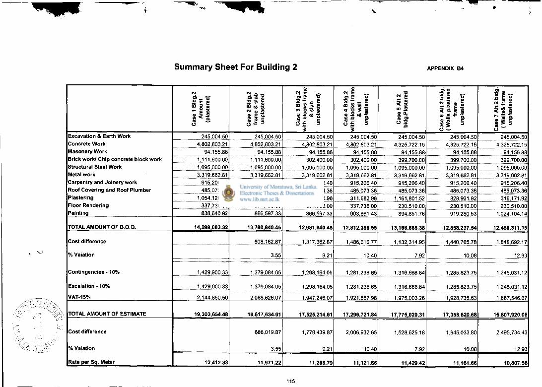
Summary Sheet For Building 2 APPENDIX B4
Cas
e 1
Bld
g.2
Am
ount
(p
last
ered
)
Cas
e 2
Bld
g.2
fram
e &
sla
b
unpl
aste
red
Cas
e 3
Bld
g.2
with
blo
cks
fram
e &
slab
un
plas
tere
d)
Cas
e 4
Bld
g.2
w
ith b
lock
s fr
ame
&w
all
unpl
aste
red)
Cas
e 5
Alt.
2 b
ldg
.Pla
ster
ed
Cas
e 6
Alt.
2 bl
dg.
(Wal
ls p
last
ered
fr
ame
unpl
aste
red)
Cas
e 7
Alt.
2 b
ldg
. (W
alls
& f
ram
e un
plas
tere
d)
Excavation & Earth Work Concrete Work Masonary Work
Brick work/ Chip concrete block work Structural Steel Work Metal work Carpentry and Joinery work Roof Covering and Roof Plumber Plastering Floor Rendering Painting
245,004.50 245,004.50 245,004.50 245,004.50 245,004.50 245,004.50 245,004.50 Excavation & Earth Work Concrete Work Masonary Work
Brick work/ Chip concrete block work Structural Steel Work Metal work Carpentry and Joinery work Roof Covering and Roof Plumber Plastering Floor Rendering Painting
4,802,803.21 4,802,803.21 4,802,803.21 4,802,803.21 4,325,722.15 4,325,722.15 4,325,722.15
Excavation & Earth Work Concrete Work Masonary Work
Brick work/ Chip concrete block work Structural Steel Work Metal work Carpentry and Joinery work Roof Covering and Roof Plumber Plastering Floor Rendering Painting
94,155.88 94,155.88 94,155.88 94,155.88 94,155.88 94,155.88 94,155.88
Excavation & Earth Work Concrete Work Masonary Work
Brick work/ Chip concrete block work Structural Steel Work Metal work Carpentry and Joinery work Roof Covering and Roof Plumber Plastering Floor Rendering Painting
1,111,600.00 1,111,600.00 302,400.00 302,400.00 399,700.00 399,700.00 399,700.00
Excavation & Earth Work Concrete Work Masonary Work
Brick work/ Chip concrete block work Structural Steel Work Metal work Carpentry and Joinery work Roof Covering and Roof Plumber Plastering Floor Rendering Painting
1,095,000.00 1,095,000.00 1,095,000.00 1,095,000.00 1,095,000.00 1,095,000.00 1,095,000.00
Excavation & Earth Work Concrete Work Masonary Work
Brick work/ Chip concrete block work Structural Steel Work Metal work Carpentry and Joinery work Roof Covering and Roof Plumber Plastering Floor Rendering Painting
3,319,662.81 3,319,662.81 3,319,662.81 3,319,662.81 3,319,662.81 3,319,662.81 3,319,662.81
Excavation & Earth Work Concrete Work Masonary Work
Brick work/ Chip concrete block work Structural Steel Work Metal work Carpentry and Joinery work Roof Covering and Roof Plumber Plastering Floor Rendering Painting
915,206.40 915,206.40 915,206.40 915,206.40 915,206.40 915,206.40 915,206.40
Excavation & Earth Work Concrete Work Masonary Work
Brick work/ Chip concrete block work Structural Steel Work Metal work Carpentry and Joinery work Roof Covering and Roof Plumber Plastering Floor Rendering Painting
485,073.36 485,073.36 485,073.36 485,073.36 485,073.36 485,073.36 485,073.36
Excavation & Earth Work Concrete Work Masonary Work
Brick work/ Chip concrete block work Structural Steel Work Metal work Carpentry and Joinery work Roof Covering and Roof Plumber Plastering Floor Rendering Painting
1,054,120.24 518,000.96 518,000.96 311,682.96 1,161,801.52 828,921.92 316,171.92
Excavation & Earth Work Concrete Work Masonary Work
Brick work/ Chip concrete block work Structural Steel Work Metal work Carpentry and Joinery work Roof Covering and Roof Plumber Plastering Floor Rendering Painting
337,736.00 337,736.00 337,736.00 337,736.00 230,510.00 230,510.00 230,510.00
Excavation & Earth Work Concrete Work Masonary Work
Brick work/ Chip concrete block work Structural Steel Work Metal work Carpentry and Joinery work Roof Covering and Roof Plumber Plastering Floor Rendering Painting 838,640.92 866,597.33 866,597.33 903,661.43 894,851.76 919,280.53 1,024,104.14
TOTAL AMOUNT OF B.O.Q. 14,299,003.32 13,790,840.45 12,981,640.45 12,812,386.55 13,166,688.38 12,858,237.54 12,450,311.15
Cost difference
% Vaiation
Contingencies • 10%
Escalation - 1 0 %
VAT-15%
508,162.87 1,317,362.87 1,486,616.77 1,132,314.95 1,440,765.78 1,848,692.17 Cost difference
% Vaiation
Contingencies • 10%
Escalation - 1 0 %
VAT-15%
3.55 9.21 10.40 7.92 10.08 12.93
Cost difference
% Vaiation
Contingencies • 10%
Escalation - 1 0 %
VAT-15%
1,429,900.33 1,379,084.05 1,298,164.05 1,281,238.65 1,316,668.84 1,285,823.75 1,245,031.12
Cost difference
% Vaiation
Contingencies • 10%
Escalation - 1 0 %
VAT-15%
1,429,900.33 1,379,084.05 1,298,164.05 1,281,238.65 1,316,668.84 1,285,823.75 1,245,031.12
Cost difference
% Vaiation
Contingencies • 10%
Escalation - 1 0 %
VAT-15% 2,144,850.50 2,068,626.07 1,947,246.07 1,921,857.98 1,975,003.26 1,928,735.63 1,867,546.67
TOTAL AMOUNT OF ESTIMATE 19,303,654.48 18,617,634.61 17,525,214.61 17,296,721.84 17,775,029.31 17,358,620.68 16,807,920.06
Cost difference
% Vaiation
Rate per Sq. Meter
686,019.87
3.55
1,778,439.87
9.21
2,006,932.65
10.40
1,528,625.18
7.92
1,945,033.80
10.08
2,495,734.43
12.93
Cost difference
% Vaiation
Rate per Sq. Meter 12,412.33 11,971.22 11,268.79 11,121.86 11,429.42 11,161.66 10,807.56
115