concrete anchoring specialists - itw red … · concrete anchoring specialists submittal...
TRANSCRIPT

Submittal InformationCONCRETE ANCHORING SPECIALISTS
1-800-899-7890 40 www.itwredhead.com02/12
SPECIFIED FOR ANCHORAGE INTO CONCRETE
Trubolt Wedge anchors feature a stainless steel expansion clip, threaded stud body, nut and washer. Anchor bodies are made of plated carbon steel, hot-dipped galvanized carbon steel, type 304 stainless steel or type 316 stainless steel as identified in the drawings or other notations.
The exposed end of the anchor is stamped to identify anchor length. Stampings should be preserved during installation for any subsequent embedment verification.
Use carbide tipped hammer drill bits made in accordance with ANSI B212.15-1994 to install anchors.
Anchors are tested to ACI 355.2 and ICC-ES AC193. Anchors are listed by the following agencies as required by the local building code: ICC-ES, UL, FM, City of Los Angeles, California State Fire Marshal and Caltrans.
See pages 42-43 for performance values in accordance to 2006 IBC .
Trubolt Wedge
APPROVALS/LISTINGS
ICC Evaluation Service, Inc. # ESR-2251 – Category 1 performance rating – 2006 IBC compliant – Meets ACI 318 ductility requirements – Tested in accordance with ACI 355.2 and ICC-ES AC193 – For use in seismic zones A & B – 1/4”, 3/8” & 1/2” diameter anchors listed in ESR-2251Underwriters LaboratoriesFactory MutualCity of Los Angeles - #RR2748California State Fire MarshallCaltransMeets or exceeds U.S. Government G.S.A. Specification A-A-1923A Type 4 (formerlyGSA: FF-S-325 Group II, Type 4, Class 1)
INSTALLATION STEPS
LENGTH INDICATION CODE *CODE LENGTH OF ANCHOR CODE LENGTH OF ANCHOR
A 1-1/2 < 2 (38.1 < 50.8) K 6-1/2 < 7 (165.1 < 177.8) B 2 < 2-1/2 (50.8 < 63.5) L 7 < 7-1/2 (177.8 < 190.5) C 2-1/2 < 3 (63.5 < 76.2) M 7-1/2 < 8 (190.5 < 203.2) D 3 < 3-1/2 (76.2 < 88.9) N 8 < 8-1/2 (203.2 < 215.9) E 3-1/2 < 4 (88.9 < 101.6) O 8-1/2 < 9 (215.9 < 228.6) F 4 < 4-1/2 (101.6 < 114.3) P 9 < 9-1/2 (228.6 < 241.3) G 4-1/2 < 5 (114.3 < 127.0) Q 9-1/2 < 10 (241.3 < 254.0) H 5 < 5-1/2 (127.0 < 139.7) R 10 < 11 (254.0 < 279.4) I 5-1/2 < 6 (139.7 < 152.4) S 11 < 12 (279.4 < 304.8) J 6 < 6-1/2 (152.4 < 165.1) T 12 < 13 (304.8 < 330.2)
* Located on top of anchor for easy inspection.
1. Select a carbide drill bit with a diameter equal to the anchor diameter. Drill hole to any depth exceeding the desired embedment. See chart for minimum recommended embedment.
2. Clean hole or continue drilling additional depth to accommodate drill fines.
3. Assemble washer and nut, leaving nut flush with end of anchor to protect threads. Drive anchor through material to be fastened until washer is flush to surface of material.
4. Expand anchor by tightening nut 3-5 turns past the hand tight position, or to the specified torque requirement.
** ONLY FOR USE IN CONCRETRE**

Submittal InformationCONCRETE ANCHORING SPECIALISTS
1-800-899-7890 www.itwredhead.com02/12
41
ANCHOR INSTALLATION EMBEDMENT ANCHOR f’c = 2000 PSI (13 .8 MPa) f’c = 4000 PSI (27 .6 MPa) f’c = 6000 PSI (41 .4 MPa) DIA . TORQUE DEPTH TYPE TENSION SHEAR TENSION SHEAR TENSION SHEAR In . (mm) Ft . Lbs . (Nm) In . (mm) Lbs . (kN) Lbs . (kN) Lbs . (kN) Lbs . (kN) Lbs . (kN) Lbs . (kN)
1/4 (6.4) 4 (5.4) 1-1/8 (28.6) 1,180 (5.2) 1,400 (6.2) 1,780 (7.9) 1,400 (6.2) 1,900 (8.5) 1,400 (6.2) 1-15/16 (49.2) 2,100 (9.3) 1,680 (7.5) 3,300 (14.7) 1,680 (7.5) 3,300 (14.7) 1,680 (7.5) 2-1/8 (54.0) 2,260 (10.1) 1,680 (7.5) 3,300 (14.7) 1,680 (7.5) 3,300 (14.7) 1,680 (7.5)
3/8 (9.5) 25 (33.9) 1-1/2 (38.1) 1,680 (7.5) 2,320 (10.3) 2,240 (10.0) 2,620 (11.7) 2,840 (12.6) 3,160 (14.1) 3 (76.2) 3,480 (15.5) 4,000 (17.8) 5,940 (26.4) 4,140 (18.4) 6,120 (27.2) 4,500 (20.0) 4 (101.6) 4,800 (21.4) 4,000 (17.8) 5,940 (26.4) 4,140 (18.4) 6,120 (27.2) 4,500 (20.0)
1/2 (12.7) 55 (74.6) 2-1/4 (57.2) 4,660 (20.7) 4,760 (21.2) 5,100 (22.7) 4,760 (21.2) 7,040 (31.3) 7,040 (31.3) 4-1/8 (104.8) 4,660 (20.7) 7,240 (32.2) 9,640 (42.9) 7,240 (32.2) 10,820 (48.1) 8,160 (36.3) 6 (152.4) 5,340 (23.8) 7,240 (32.2) 9,640 (42.9) 7,240 (32.2) 10,820 (48.1) 8,160 (36.3)
5/8 (15.9) 90 (122.0) 2-3/4 (69.9) 6,580 (29.3) 7,120 (31.7) 7,180 (31.9) 7,120 (31.7) 9,720 (43.2) 9,616 (42.8 5-1/8 (130.2) 6,580 (29.3) 9,600 (42.7) 14,920 (66.4) 11,900 (52.9) 16,380 (72.9) 12,520 (55.7) 7-1/2 (190.5) 7,060 (31.4) 9,600 (42.7) 15,020 (66.8) 11,900 (52.9) 16,380 (72.9) 12,520 (55.7)
3/4 (19.1) 110 (149.2) 3-1/4 (82.6) 7,120 (31.7) 10,120 (45.0) 10,840 (48.2) 13,720 (61.0) 13,300 (59.2) 15,980 (71.1) 6-5/8 (168.3) 10,980 (48.8) 20,320 (90.4) 17,700 (78.7) 23,740 (105.6) 20,260 (90.1) 23,740 (105.6) 10 (254.0) 10,980 (48.8) 20,320 (90.4) 17,880 (79.5) 23,740 (105.6) 23,580 (104.9) 23,740 (105.6)
7/8 (22.2) 250 (339.0) 3-3/4 (95.3) 9,520 (42.3) 13,160 (58.5) 14,740 (65.6) 16,580 (73.8) 17,420 (77.5) 19,160 (85.2) 6-1/4 (158.8) 14,660 (65.2) 20,880 (92.9) 20,940 (93.1) 28,800 (128.1) 24,360 (108.4) 28,800 (128.1) 8 (203.2) 14,660 (65.2) 20,880 (92.9) 20,940 (93.1) 28,800 (128.1) 24,360 (108.4) 28,800 (128.1)
1 (25.4) 300 (406.7) 4-1/2 (114.3) 13,940 (62.0) 16,080 (71.5) 20,180 (89.8) 22,820 (101.5) 21,180 (94.2) 24,480 (108.9) 7-3/8 (187.3) 14,600 (64.9) 28,680 (127.6) 23,980 (106.7) 37,940 (168.8) 33,260 (148.0) 38,080 (169.4) 9-1/2 (241.3) 18,700 (83.2) 28,680 (127.6) 26,540 (118.1) 37,940 (168.8) 33,260 (148.0) 38,080 (169.4)
* Allowable values are based upon a 4 to 1 safety factor. Divide by 4 for allowable load values. * For Tie-Wire Wedge Anchor, TW-1400, use tension data from 1/4” diameter with 1-1/8” embedment. * For continuous extreme low temperature applications, use stainless steel.
Ultimate Tension and Shear Values (Lbs/kN) in Concrete*
WS-Carbon orWS-G
Hot-DippedGalvanized
orWW-304 S.S.
or SWW-316 S.S.
Trubolt Wedge Anchors
PERFORMANCE TABLE
Ultimate Tension and Shear Values (Lbs/kN) in Lightweight Concrete*
ANCHOR INSTALLATION EMBEDMENT ANCHOR LIGHTWEIGHT CONCRETE LOWER FLUTE OF STEEL DECK WITH DIA . TORQUE DEPTH TYPE f’c = 3000 PSI (20 .7 MPa) LIGHTWEIGHT CONCRETE FILL In . (mm) Ft . Lbs . (Nm) In . (mm) f’c = 3000 PSI (20 .7 MPa) TENSION SHEAR TENSION SHEAR Lbs . (kN) Lbs . (kN) Lbs . (kN) Lbs . (kN)
3/8 (9.5) 25 (33.9) 1-1/2 (38.1) 1,175 (5.2) 1,480 (6.6) 1,900 (8.5) 3,160 (14.1) 3 (76.2) 2,825 (12.6) 2,440 (10.9) 2,840 (12.6) 4,000 (17.8)
1/2 (12.7) 55 (74.6) 2-1/4 (57.2) 2,925 (13.0) 2,855 (12.7) 3,400 (15.1) 5,380 (23.9) 3 (76.2) 3,470 (15.4) 3,450 (15.3) 4,480 (19.9) 6,620 (29.4) 4 (101.6) 4,290 (19.1) 3,450 (15.3) 4,800 (21.4) 6,440 (28.6)
5/8 (15.9) 90 (122.0) 3 (76.2) 4,375 (19.5) 4,360 (19.4) 4,720 (21.0) 5,500 (24.5) 5 (127.0) 6,350 (28.2) 6,335 (28.2) 6,580 (29.3) 9,140 (40.7)
3/4 (19.1) 110 (149.2) 3-1/4 (82.6) 5,390 (24.0) 7,150 (31.8) 5,840 (26.0) 8,880 (39.5) 5-1/4 (133.4) 7,295 (32.5) 10,750 (47.8) 7,040 (31.3) N/A
* Allowable values are based upon a 4 to 1 safety factor. Divide by 4 for allowable load values.
WS-Carbon orWS-G
Hot-DippedGalvanized
orWW-304 S.S.
or SWW-316 S.S.
Trubolt
Wedge Anchors
PERFORMANCE TABLE
Submittal InformationCONCRETE ANCHORING SPECIALISTS
1-800-899-7890 4202/12
www.itwredhead.com
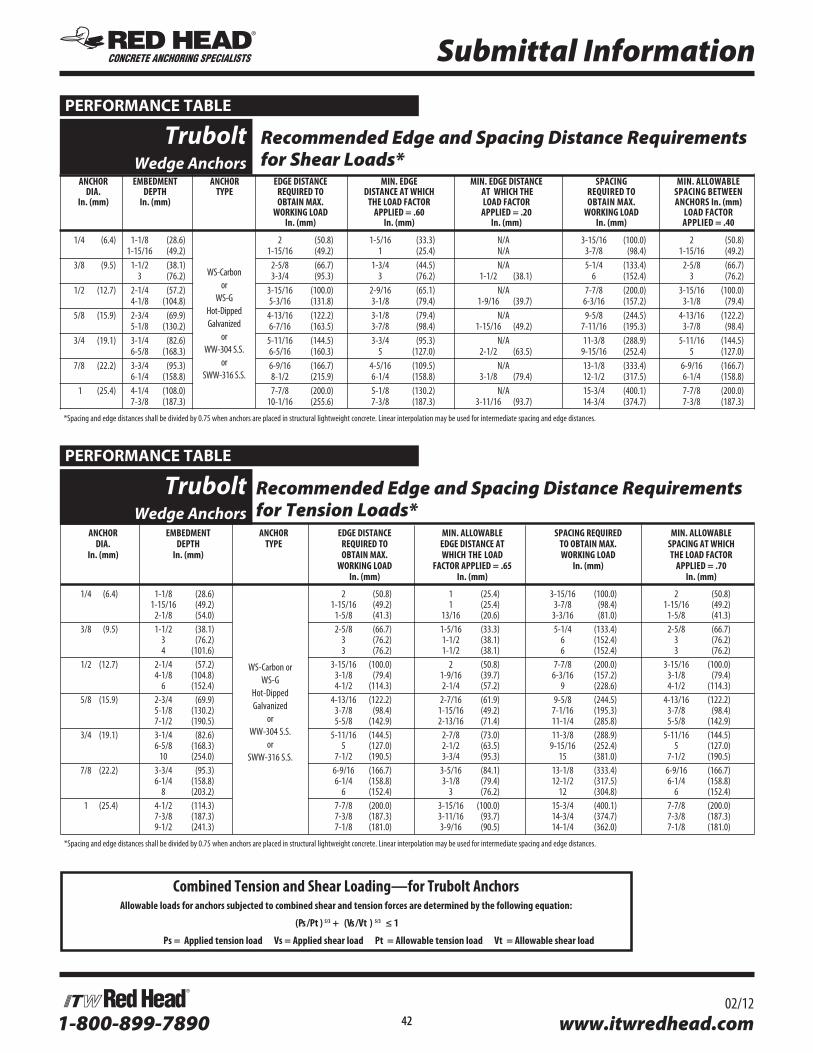
Combined Tension and Shear Loading—for Trubolt AnchorsAllowable loads for anchors subjected to combined shear and tension forces are determined by the following equation:
(Ps /Pt ) 5/3 + (Vs /Vt ) 5/3 ≤ 1
Ps = Applied tension load Vs = Applied shear load Pt = Allowable tension load Vt = Allowable shear load
ANCHOR EMBEDMENT ANCHOR EDGE DISTANCE MIN . EDGE MIN . EDGE DISTANCE SPACING MIN . ALLOWABLE DIA . DEPTH TYPE REQUIRED TO DISTANCE AT WHICH AT WHICH THE REQUIRED TO SPACING BETWEEN In . (mm) In . (mm) OBTAIN MAX . THE LOAD FACTOR LOAD FACTOR OBTAIN MAX . ANCHORS In . (mm) WORKING LOAD APPLIED = .60 APPLIED = .20 WORKING LOAD LOAD FACTOR In . (mm) In . (mm) In . (mm) In . (mm) APPLIED = .40
1/4 (6.4) 1-1/8 (28.6) 2 (50.8) 1-5/16 (33.3) N/A 3-15/16 (100.0) 2 (50.8) 1-15/16 (49.2) 1-15/16 (49.2) 1 (25.4) N/A 3-7/8 (98.4) 1-15/16 (49.2) 3/8 (9.5) 1-1/2 (38.1) 2-5/8 (66.7) 1-3/4 (44.5) N/A 5-1/4 (133.4) 2-5/8 (66.7) 3 (76.2) 3-3/4 (95.3) 3 (76.2) 1-1/2 (38.1) 6 (152.4) 3 (76.2) 1/2 (12.7) 2-1/4 (57.2) 3-15/16 (100.0) 2-9/16 (65.1) N/A 7-7/8 (200.0) 3-15/16 (100.0) 4-1/8 (104.8) 5-3/16 (131.8) 3-1/8 (79.4) 1-9/16 (39.7) 6-3/16 (157.2) 3-1/8 (79.4) 5/8 (15.9) 2-3/4 (69.9) 4-13/16 (122.2) 3-1/8 (79.4) N/A 9-5/8 (244.5) 4-13/16 (122.2) 5-1/8 (130.2) 6-7/16 (163.5) 3-7/8 (98.4) 1-15/16 (49.2) 7-11/16 (195.3) 3-7/8 (98.4) 3/4 (19.1) 3-1/4 (82.6) 5-11/16 (144.5) 3-3/4 (95.3) N/A 11-3/8 (288.9) 5-11/16 (144.5) 6-5/8 (168.3) 6-5/16 (160.3) 5 (127.0) 2-1/2 (63.5) 9-15/16 (252.4) 5 (127.0) 7/8 (22.2) 3-3/4 (95.3) 6-9/16 (166.7) 4-5/16 (109.5) N/A 13-1/8 (333.4) 6-9/16 (166.7) 6-1/4 (158.8) 8-1/2 (215.9) 6-1/4 (158.8) 3-1/8 (79.4) 12-1/2 (317.5) 6-1/4 (158.8) 1 (25.4) 4-1/4 (108.0) 7-7/8 (200.0) 5-1/8 (130.2) N/A 15-3/4 (400.1) 7-7/8 (200.0) 7-3/8 (187.3) 10-1/16 (255.6) 7-3/8 (187.3) 3-11/16 (93.7) 14-3/4 (374.7) 7-3/8 (187.3)
* Spacing and edge distances shall be divided by 0.75 when anchors are placed in structural lightweight concrete. Linear interpolation may be used for intermediate spacing and edge distances.
WS-Carbon or
WS-GHot-DippedGalvanized
orWW-304 S.S.
or SWW-316 S.S.
Trubolt
Wedge Anchors Recommended Edge and Spacing Distance Requirements for Shear Loads*
PERFORMANCE TABLE
Recommended Edge and Spacing Distance Requirements for Tension Loads*
ANCHOR EMBEDMENT ANCHOR EDGE DISTANCE MIN . ALLOWABLE SPACING REQUIRED MIN . ALLOWABLE DIA . DEPTH TYPE REQUIRED TO EDGE DISTANCE AT TO OBTAIN MAX . SPACING AT WHICH In . (mm) In . (mm) OBTAIN MAX . WHICH THE LOAD WORKING LOAD THE LOAD FACTOR WORKING LOAD FACTOR APPLIED = .65 In . (mm) APPLIED = .70 In . (mm) In . (mm) In . (mm)
1/4 (6.4) 1-1/8 (28.6) 2 (50.8) 1 (25.4) 3-15/16 (100.0) 2 (50.8) 1-15/16 (49.2) 1-15/16 (49.2) 1 (25.4) 3-7/8 (98.4) 1-15/16 (49.2) 2-1/8 (54.0) 1-5/8 (41.3) 13/16 (20.6) 3-3/16 (81.0) 1-5/8 (41.3) 3/8 (9.5) 1-1/2 (38.1) 2-5/8 (66.7) 1-5/16 (33.3) 5-1/4 (133.4) 2-5/8 (66.7) 3 (76.2) 3 (76.2) 1-1/2 (38.1) 6 (152.4) 3 (76.2) 4 (101.6) 3 (76.2) 1-1/2 (38.1) 6 (152.4) 3 (76.2) 1/2 (12.7) 2-1/4 (57.2) 3-15/16 (100.0) 2 (50.8) 7-7/8 (200.0) 3-15/16 (100.0) 4-1/8 (104.8) 3-1/8 (79.4) 1-9/16 (39.7) 6-3/16 (157.2) 3-1/8 (79.4) 6 (152.4) 4-1/2 (114.3) 2-1/4 (57.2) 9 (228.6) 4-1/2 (114.3) 5/8 (15.9) 2-3/4 (69.9) 4-13/16 (122.2) 2-7/16 (61.9) 9-5/8 (244.5) 4-13/16 (122.2) 5-1/8 (130.2) 3-7/8 (98.4) 1-15/16 (49.2) 7-1/16 (195.3) 3-7/8 (98.4) 7-1/2 (190.5) 5-5/8 (142.9) 2-13/16 (71.4) 11-1/4 (285.8) 5-5/8 (142.9) 3/4 (19.1) 3-1/4 (82.6) 5-11/16 (144.5) 2-7/8 (73.0) 11-3/8 (288.9) 5-11/16 (144.5) 6-5/8 (168.3) 5 (127.0) 2-1/2 (63.5) 9-15/16 (252.4) 5 (127.0) 10 (254.0) 7-1/2 (190.5) 3-3/4 (95.3) 15 (381.0) 7-1/2 (190.5) 7/8 (22.2) 3-3/4 (95.3) 6-9/16 (166.7) 3-5/16 (84.1) 13-1/8 (333.4) 6-9/16 (166.7) 6-1/4 (158.8) 6-1/4 (158.8) 3-1/8 (79.4) 12-1/2 (317.5) 6-1/4 (158.8) 8 (203.2) 6 (152.4) 3 (76.2) 12 (304.8) 6 (152.4) 1 (25.4) 4-1/2 (114.3) 7-7/8 (200.0) 3-15/16 (100.0) 15-3/4 (400.1) 7-7/8 (200.0) 7-3/8 (187.3) 7-3/8 (187.3) 3-11/16 (93.7) 14-3/4 (374.7) 7-3/8 (187.3) 9-1/2 (241.3) 7-1/8 (181.0) 3-9/16 (90.5) 14-1/4 (362.0) 7-1/8 (181.0)
* Spacing and edge distances shall be divided by 0.75 when anchors are placed in structural lightweight concrete. Linear interpolation may be used for intermediate spacing and edge distances.
WS-Carbon orWS-G
Hot-DippedGalvanized
orWW-304 S.S.
or SWW-316 S.S.
Trubolt
Wedge Anchors
PERFORMANCE TABLE

1-800-899-7890 43 www.itwredhead.com02/12
Trubolt Strength Design Performance values in accordance to 2006 IBCITW RED HEAD TRUBOLT WEDGE ANCHOR
DESIGN INFORMATION TESTED TO ICC-ES AC193 AND ACI 355 .2, IN ACCORDANCE WITH 2006 IBC
TRUBOLT WEDGE ANCHOR DESIGN INFORMATION1,2,3
DESIGN INFORMATION Symbol UnitsNominal Anchor Diameter
1/4 3/8 1/2 5/8 3/4
Anchor O.D. do in 0.250 0.375 0.500 0.625 0.750
Effective embedment hef in 1-1/2 2 1-3/4 2-5/8 1-7/8 3-3/8 2-1/2 4 3-1/2 4-3/4
Minimum member thickness hmin in 4 4 4 5 5 6 5 8 6 8
Critical edge distance cac in 2-5/8 3 2-5/8 5-1/4 3-3/4 6-3/4 5 8 7 9
Minimum edge distance cmin in 1-3/4 1-1/2 2-1/4 2 3-3/4 3-3/4 4-1/4 3-1/4 3-3/4 3-1/2
Minimum anchor spacing smin in 1-3/4 1-1/2 2-1/4 2 3-3/4 3-3/4 4-1/4 3-1/4 3-3/4 3-1/2
Min. Specified Yield Strength fy lb/in2 55,000
Min. Specified Ultimate Strength futa lb/in2 75,000
Effective tensile stress area Ase in2 0.032 0.078 0.142 0.226 0.334
Steel strength in tension Ns lb 2,385 5,815 10,645 16,950 25,050
Steel strength in shear Vs lb 1,430 2,975 3,490 4,450 6,385 6,045 10,170 10,990 15,030
Pullout strength, uncracked concrete Np,uncr lb 1,392 1,706 2,198 3,469 2,400 4,168 4,155 6,638 8,031 10,561
Anchor Category (All anchors are ductile) 1
Effectiveness factor kuncr uncracked concrete 24
Axial stiffness in service load range b lb/in 14,651 9,385 17,515 26,424 32,483 26,136 42,899 21,749 43,576 28,697
Coefficient for variation for axial stiffness in service load range 34 47 28 45 17 33 55 22 63 28
Strength reduction factor f for tension, steel failure modes 0.75
Strength reduction factor f for shear, steel failure modes 0.65
Strength reduction factor f for tension, concrete failure modes, Condition B 0.65
Strength reduction factor f for shear, concrete failure modes, Condition B 0.70
1 Trubolt+ Anchor Design Strengths must be determined in accordance with ACI 318-05 Appendix D and this table2 The Trubolt+ Wedge Anchor is a ductile steel element as defined by ACI 318 D.13 1/4", 3/8", & 1/2" diameter data is listed in ICC-ES ESR-2251.
TRUBOLT WEDGE ANCHOR (INSTALLED) TRUBOLT WEDGE INSTALLATION INFORMATION
Symbol UnitsNominal Anchor Diameter (in.)
1/4 3/8 1/2 5/8 3/4Anchor outer
diameter do in 0.25 0.375 0.5 0.625 0.750
Nominal carbide bit diameter dbit in 1/4 3/8 1/2 5/8 3/4
Effective embedment depth hef in 1-1/2 2 1-3/4 2-5/8 1-7/8 3-3/8 2-1/2 4 3-1/2 4-3/4
Min hole depth ho in 2 2-1/2 2-1/2 3-3/8 2-3/4 4-1/4 3-3/4 5-1/4 4-3/4 6
Min slab thickness hmin in 4 4 5 5 6 5 8 6 8
Installation torque Tinst ft-lb 4 25 55 90 110Min hole diameter
in fixture dh in 5/16 7/16 9/16 11/16 13/16

1-800-899-7890 44 www.itwredhead.com02/12
Trubolt Strength Design Performance values in accordance to 2006 IBC
TRUBOLT WEDGE PULLOUT STRENGTH (Np, unc) (POUNDS) 1 Nominal Anchor
Diameter (in.)Effective
Embedment Depth (in.)Concrete Compressive Strength
f’c = 2,500 psi f’c = 3,000 psi f’c = 4,000 psi f’c = 6,500 psi
1/41-1/2 1,392 1,525 1,610 1,822
2 1,706 1,869 1,947 2,151
3/81-3/4 2,198 2,408 2,621 3,1532-5/8 3,469 3,800 3,936 4,275
1/21-7/8 2,400 2,629 3,172 4,5203-3/8 4,168 4,520 4,520 4,520
5/82-1/2 4,155 4,155 4,376 5,578
4 6,638 6,900 7,968 10,157
3/43-1/2 8,031 8,322 9,610 12,2514-3/4 10,561 10,561 10,561 12,251
For SI: 1 inch = 25.4 mm, 1 lbf = 4.45 N, 1 psi = 0.006895 Mpa 1 Values are for single anchors with no edge distance or spacing reduction.
TRUBOLT WEDGE ANCHOR ALLOWABLE STATIC TENSION (ASD), NORMAL-WEIGHT UNCRACKED CONCRETE 1-6
Nominal Anchor Diameter (in.)
Effective Embedment Depth (in.)
Concrete Compressive Strengthf’c = 2,500 psi f’c = 3,000 psi f’c = 4,000 psi f’c = 6,500 psi
1/41-1/2 611 670 707 800
2 749 821 855 945
3/81-3/4 965 1,058 1,151 1,3852-5/8 1,524 1,669 1,729 1,878
1/21-7/8 1,054 1,155 1,393 1,9853-3/8 1,831 1,985 1,985 1,985
5/82-1/2 1,825 1,825 1,922 2,450
4 2,915 3,030 3,499 4,461
3/43-1/2 3,527 3,655 4,221 5,3814-3/4 4,638 4,638 4,638 5,381
For SI: 1 inch = 25.4 mm, 1 lbf = 4.45 N, 1 psi = 0.006895 Mpa Design Assumptions:1 Single anchor with static tension load only. 2 Concrete determined to remain uncracked for the life of the anchorage.3 Load combinations from 2006 IBC, Sections 1605.2.1 and 1605.3.1 (no seismic loading).4 Thirty percent dead load and 70 percent live load, controlling load combination 1.2D + 1.6L5 Calculation of weighted average: 1.2D + 1.6L = 1.2 (0.3) + 1.6 (0.7) = 1.486 Values do not include edge distance or spacing reductions.
TRUBOLT WEDGE ANCHOR ALLOWABLE STATIC SHEAR (ASD), STEEL (POUNDS)1-5 Nominal Anchor Diameter (in.) Effective Embedment Depth (in.) Allowable Steel Capacity, Static Shear
1/41-1/2
6282
3/81-3/4 1,3072-5/8 1,533
1/21-7/8 1,9543-3/8 2,804
5/82-1/2 2,655
4 4,467
3/43-1/2 4,8274-3/4 6,601
For SI: 1 inch = 25.4 mm, 1 lbf = 4.45 N, 1 psi = 0.006895 Mpa Design Assumptions:1 Single anchor with static shear load only. 3 Load combinations from 2006 IBC, Sections 1605.2.1 and 1605.3.1 (no seismic loading).3 Thirty percent dead load and 70 percent live load, controlling load combination 1.2D + 1.6L 4 Calculation of weighted average: 1.2D + 1.6L = 1.2 (0.3) + 1.6 (0.7) = 1.485 Values do not include edge distance or spacing reductions.
2006 IBC
Compliant

67Call our toll free number 800-848-5611 or visit our web site for the most current product and technical information at www.itwredhead.com
SELECTION CHARTS
Trubolt Carbon Steel with Zinc Plating
PART THREAD ANCHOR DIA. OVERALL MAX. THICKNESS QTY/WT QTY/WT NUMBER LENGTH & DRILL BIT LENGTH OF MATERIAL PER BOX PER MASTER In. (mm) SIZE (THREADS) In. (mm) TO BE FASTENED lbs. CARTON PER INCH In. (mm) lbs. WS-1416 3/4 (19.1) 1/4” - 20 1-3/4 (44.5) 3/8 (9.5) 100/ 3.1 1000/ 32 WS-1422 1-1/4 (31.8) 2-1/4 (57.2) 7/8 (22.2) 100/ 3.6 1000/ 37 WS-1432 2-1/4 (57.2) 3-1/4 (82.6) 1-7/8 (47.6) 100/ 4.7 800/ 39 WS-3822 1-1/8 (28.6) 3/8” - 16 2-1/4 (57.2) 3/8 (9.5) 50/ 4.1 500/ 41 WS-3826 1-5/8 (41.3) 2-3/4 (69.9) 7/8 (22.2) 50/ 4.7 400/ 39 WS-3830 1-3/4 (44.5) 3 (76.2) 1-1/8 (28.6) 50/ 5.0 400/ 41 WS-3836 2-1/2 (63.5) 3-3/4 (95.3) 1-7/8 (47.6) 50/ 5.9 300/ 36 WS-3850 3-3/4 (95.2) 5 (127.0) 3-1/8 (79.4) 50/ 7.4 250/ 38 WS-3870 3-7/8 (98.4) 7 (177.8) 5-1/8 (130.2) 50/ 10.4 250/ 53 WS-1226 1-1/4 (31.8) 1/2” - 13 2-3/4 (69.9) 1/8 (3.2) 25/ 4.6 200/ 38 WS-1236 2-1/4 (57.2) 3-3/4 (95.3) 1 (25.4) 25/ 5.7 150/ 35 WS-1242 2-3/4 (69.9) 4-1/4 (108.0) 1-1/2 (38.1) 25/ 6.2 150/ 38 WS-1244 3 (76.2) 4-1/2 (114.3) 1-3/4 (44.5) 25/ 6.5 150/ 39 WS-1254 4 (101.6) 5-1/2 (139.7) 2-3/4 (69.9) 25/ 7.7 150/ 47 WS-1270 5-1/2 (139.7) 7 (177.8) 4-1/4 (108.0) 25/ 9.3 150/ 57 WS-5834 1-3/4 (44.5) 5/8” - 11 3-1/2 (88.9) 1/8 (3.2) 10/ 3.6 100/ 37 WS-5842 2-1/2 (63.5) 4-1/4 (108.0) 7/8 (22.2) 10/ 4.1 100/ 42 WS-5850 3-1/4 (82.6) 5 (127.0) 1-5/8 (41.3) 10/ 4.7 100/ 48 WS-5860 4-1/4 (107.9) 6 (152.4) 2-5/8 (66.7) 10/ 5.4 50/ 28 WS-5870 5-1/4 (133.4) 7 (177.8) 3-5/8 (92.1) 10/ 6.2 30/ 19 WS-5884 5-3/4 (146.0) 8-1/2 (215.9) 5-1/8 (130.2) 10/ 8.0 30/ 25 WS-58100 5-3/4 (146.0) 10 (254.0) 6-5/8 (168.3) 10/ 9.4 30/ 29 WS-3442 2-3/8 (60.3) 3/4” - 10 4-1/4 (108.0) 1/4 (31.8) 10/ 6.8 60/ 42 WS-3446 2-7/8 (73.0) 4-3/4 (120.7) 3/4 (19.1) 10/ 7.4 60/ 45 WS-3454 3-5/8 (92.1) 5-1/2 (139.7) 1-1/2 (38.1) 10/ 8.1 50/ 41 WS-3462 4-3/8 (111.1) 6-1/4 (158.8) 2-1/4 (57.2) 10/ 9.1 30/ 28 WS-3470 5-1/8 (130.2) 7 (177.8) 3 (76.2) 10/ 9.7 30/ 30 WS-3484 5-3/4 (146.0) 8-1/2 (215.9) 4-1/2 (114.3) 10/ 12.3 30/ 38 WS-34100 5-3/4 (146.0) 10 (254.0) 6 (152.4) 10/ 14.0 30/ 43 WS-34120 1-3/4 (44.5) 12 (304.8) 8 (203.2) 10/ 16.6 30/ 51 WS-7860 2-1/2 (63.5) 7/8” - 9 6 (152.4) 1-3/8 (34.9) 5/ 6.3 25/ 32 WS-7880 2-1/2 (63.5) 8 (203.2) 3-3/8 (85.7) 5/ 8.1 15/ 25 WS-78100 2-1/2 (63.5) 10 (254.0) 5-3/8 (136.5) 5/ 9.8 15/ 30 WS-10060 2-1/2 (63.5) 1” - 8 6 (152.4) 1/2 (12.7) 5/ 8.3 25/ 43 WS-10090 2-1/2 (63.5) 9 (228.6) 3-1/2 (88.9) 5/ 11.6 15/ 36 WS-100120 2-1/2 (63.5) 12 (304.8) 6-1/2 (165.1) 5/ 15.0 15/ 46 TIE WIRE TW-1400 N/A 1/4” 2-1/8 (54.0) 9/32 -hole (7.1) 100/ 3.6 1000/ 36 TW-1400 K N/A 2-1/8 (54.0) 9/32 -hole (7.1) BULK 1500/ 73
Typical Applications—Structural Columns, Machinery, Equipment, etc.Environment—Interior (non-corrosive) Level of Corrosion—Low
Meets ASTM B633 SC1, Type III specifications for electroplating of 5um = .0002” thickness. This material is well suited for non-corrosive environments.
Tie Wire Wedge for hanging suspended ceiling
Typical Applications—Railings, Signage, Awnings, etc.Environment—Rural/Suburban (exterior environ-ment— essentially unpolluted areas) Level of Corrosion— Low to Medium
Trubolt Carbon Steel with Hot-Dipped Galvanizing
PART THREAD ANCHOR DIA. OVERALL MAX. THICKNESS QTY/WT QTY/WT NUMBER LENGTH & DRILL BIT LENGTH OF MATERIAL PER BOX PER MASTER In. (mm) SIZE (THREADS) In. (mm) TO BE FASTENED lbs. CARTON PER INCH In. (mm) lbs. WS-1226G 1-1/4 (31.8) 1/2” - 13 2-3/4 (69.9) 1/8 (3.2) 25/ 4.8 200/ 39 WS-1242G 2-3/4 (69.9) 4-1/4 (108.0) 1-1/2 (38.1) 25/ 6.7 150/ 41 WS-1254G 4 (101.6) 5-1/2 (139.7) 2-3/4 (69.9) 25/ 8.0 150/ 49 WS-1270G 5-1/2 (139.7) 7 (177.8) 4-1/4 (108.0) 25/ 9.7 150/ 59 WS-5834G 1-3/4 (44.5) 5/8” - 11 3-1/2 (88.9) 1/8 (3.2) 10/ 3.7 100/ 38 WS-5860G 4-1/4 (107.9) 6 (152.4) 2-5/8 (66.7) 10/ 5.6 50/ 29 WS-3446G 2-7/8 (73.0) 3/4” - 10 4-3/4 (120.7) 3/4 (19.1) 10/ 7.5 60/ 46 WS-3454G 3-5/8 (92.1) 5-1/2 (139.7) 1-1/2 (38.1) 10/ 8.4 50/ 42 WS-3484G 5-3/4 (146.0) 8-1/2 (215.9) 4-1/2 (114.3) 10/ 12.5 30/ 38
Meets ASTM A153 Class specifications for hot-dipped galvanizing > 45um = .002”. It is highly recommended for damp, humid environments near coastal regions. Hot-dipped galvanized Trubolts have a coating thickness of zinc that is almost 10 times as thick as electroplating. This creates greater corrosion resistance at a minimal cost.
SELECTION CHARTS

68 Call our toll free number 800-848-5611 or visit our web site for the most current product and technical information at www.itwredhead.com
PART THREAD ANCHOR DIA. OVERALL MAX. QTY/WT QTY/WT NUMBER LENGTH & DRILL BIT LENGTH THICKNESS PER BOX PER MASTER In. (mm) SIZE (THREADS) In. (mm) OF MATERIAL lbs. CARTON PER INCH TO BE FASTENED lbs. In. (mm) WW-1416 3/4 (19.1) 1/4” - 20 1-3/4 (44.5) 3/8 (9.5) 100/ 3.2 1000/ 32 WW-1422 1-1/4 (31.8) 2-1/4 (57.2) 7/8 (22.2) 100/ 3.7 1000/ 37 WW-1432 2-1/4 (57.2) 3-1/4 (82.6) 1-7/8 (47.6) 100/ 4.8 800/ 39 WW-3822 1-1/8 (28.6) 3/8” - 16 2-1/4 (57.2) 3/8 (9.5) 50/ 4.1 500/ 41 WW-3826 1-5/8 (41.3) 2-3/4 (69.9) 7/8 (22.2) 50/ 4.8 400/ 39 WW-3830 1-3/4 (44.5) 3 (76.2) 1-1/8 (28.6) 50/ 5.1 400/ 42 WW-3836 2-1/2 (63.5) 3-3/4 (95.3) 1-7/8 (47.6) 50/ 6.0 300/ 37 WW-3850 3-3/4 (95.3) 5 (127.0) 3-1/8 (79.4) 50/ 7.5 250/ 39 WW-1226 1-1/4 (31.8) 1/2” - 13 2-3/4 (69.9) 1/8 (3.2) 25/ 4.7 200/ 38 WW-1236 2-1/4 (57.2) 3-3/4 (95.3) 1 (25.4) 25/ 5.8 150/ 36 WW-1242 2-3/4 (69.9) 4-1/4 (108.0) 1-1/2 (38.1) 25/ 6.3 150/ 39 WW-1254 3 (76.2) 5-1/2 (139.7) 2-3/4 (69.9) 25/ 7.7 150/ 47 WW-1270 3-1/2 (88.9) 7 (177.8) 4-1/4 (108.0) 25/ 9.4 150/ 57 WW-5834 1-3/4 (44.5) 5/8” - 11 3-1/2 (88.9) 1/8 (3.2) 10/ 3.6 100/ 37 WW-5842 2-1/2 (63.5) 4-1/4 (108.0) 7/8 (22.2) 10/ 4.2 100/ 43 WW-5850 3-1/4 (82.6) 5 (127.0) 1-5/8 (41.3) 10/ 4.8 100/ 49 WW-5860 4-1/4 (107.9) 6 (152.4) 2-5/8 (66.7) 10/ 5.5 50/ 28 WW-5870 3-1/2 (88.9) 7 (177.8) 3-5/8 (92.1) 10/ 6.2 30/ 20 WW-5884 3-1/2 (88.9) 8-1/2 (215.9) 5-1/8 (130.2) 10/ 8.0 30/ 25 WW-3446 2-7/8 (73.0) 3/4” - 10 4-3/4 (120.7) 3/4 (19.1) 10/ 6.7 60/ 41 WW-3454 3-5/8 (92.1) 5-1/2 (139.7) 1-1/2 (38.1) 10/ 7.5 50/ 38 WW-3470 3-1/2 (88.9) 7 (177.8) 3 (76.2) 10/ 9.2 30/ 28 WW-3484 3-1/2 (88.9) 8-1/2 (215.9) 4-1/2 (114.3) 10/ 12.3 30/ 38 WW-34100 1-3/4 (44.5) 10 (254.0) 6 (152.4) 10/ 13.5 30/ 42 WW-10060 2-1/2 (63.5) 1” - 8 6 (152.4) 1/2 (12.7) 5/ 8.3 25/ 43 WW-10090 2-1/2 (63.5) 9 (228.6) 3-1/2 (88.9) 5/ 11.4 15/ 35* For continuous extreme low temperature applications, use stainless steel.
Trubolt Type 304Stainless Steel
Typical Applications—Cladding, Stadium Seating, etc.Environment—Urban (slight to moderate degree of pollution) Level of Corrosion—Medium
Serves many applications well. It withstands rusting in architectural and food processing environments and resists organic chemicals, dye stuffs and many inorganic chemicals.
SELECTION CHARTS
Trubolt Type 316 Stainless Steel
Contains more nickel and chromium than Type 304, and 2%-3% molybdenum, which gives it better corrosion resistance. It is especially more effective in chloride environments that tend to cause pitting.
PART THREAD ANCHOR DIA. OVERALL MAX. QTY/WT QTY/WT NUMBER LENGTH & DRILL BIT LENGTH THICKNESS PER BOX PER MASTER In. (mm) SIZE (THREADS) In. (mm) OF MATERIAL lbs. CARTON PER INCH TO BE FASTENED lbs. In. (mm)
SWW-1422 1-1/4 (31.8) 1/4” - 20 2-1/4 (57.2) 7/8 (22.2) 100/ 3.7 1000/ 37 SWW-1432 2-1/4 (57.2) 3-1/4 (82.6) 1-1/8 (28.6) 100/ 4.8 1000/ 39 SWW-3822 1-1/8 (28.6) 3/8” - 16 2-1/4 (57.2) 3/8 (9.5) 50/ 4.1 500/ 41 SWW-3826 1-5/8 (41.3) 2-3/4 (69.9) 7/8 (22.2) 50/ 4.8 400/ 39 SWW-3830 1-3/4 (44.5) 3 (76.2) 1-1/8 (28.6) 50/ 5.2 400/ 42 SWW-3836 2-1/2 (63.5) 3-3/4 (95.5) 1-7/8 (47.6) 50/ 6.0 300/ 37 SWW-3850 3-3/4 (95.3) 5 (127.0) 3-1/8 (79.4) 50/ 7.5 250/ 39 SWW-1226 1-1/4 (31.8) 1/2” - 13 2-3/4 (69.9) 1/8 (3.2) 25/ 4.7 200/ 39 SWW-1236 2-1/4 (57.2) 3-3/4 (95.3) 1 (25.4) 25/ 5.8 150/ 36 SWW-1242 2-3/4 (69.9) 4-1/4 (108.0) 1-1/2 (38.1) 25/ 6.5 150/ 40 SWW-1254 3 (76.2) 5-1/2 (139.7) 2-3/4 (69.9) 25/ 7.8 150/ 48 SWW-5842 2-1/2 (63.5) 5/8” - 11 4-1/4 (108.0) 7/8 (22.2) 10/ 4.2 100/ 43 SWW-5850 3-1/4 (82.6) 5 (127.0) 1-5/8 (41.3) 10/ 4.8 100/ 49 SWW-5870 3-1/2 (88.9) 7 (177.8) 3-5/8 (92.1) 10/ 6.7 30/ 21 * For continuous extreme low temperature applications, use stainless steel.
Typical Applications— Pumps, Diffusers, Gates, Weir Plates, etc.Environment—Industrial (moderate to heavy atmospheric pollution)Level of Corrosion— Medium to High
Typical Applications—Tunnels, Dams, Tiles, Lighting Fixtures, etc.Environment— Marine (heavy atmospheric pollution) Level of Corrosion—High
SELECTION CHARTS